installation and configuration guide cisco unified contact ... · server2008r2 126 appendix a...
TRANSCRIPT

Installation and Configuration Guide Cisco Unified Contact CenterEnterprise Release 9.0(1)First Published: May 07, 2012
Last Modified: April 24, 2013
Americas HeadquartersCisco Systems, Inc.170 West Tasman DriveSan Jose, CA 95134-1706USAhttp://www.cisco.comTel: 408 526-4000 800 553-NETS (6387)Fax: 408 527-0883

THE SPECIFICATIONS AND INFORMATION REGARDING THE PRODUCTS IN THIS MANUAL ARE SUBJECT TO CHANGE WITHOUT NOTICE. ALL STATEMENTS,INFORMATION, AND RECOMMENDATIONS IN THIS MANUAL ARE BELIEVED TO BE ACCURATE BUT ARE PRESENTED WITHOUT WARRANTY OF ANY KIND,EXPRESS OR IMPLIED. USERS MUST TAKE FULL RESPONSIBILITY FOR THEIR APPLICATION OF ANY PRODUCTS.
THE SOFTWARE LICENSE AND LIMITEDWARRANTY FOR THE ACCOMPANYING PRODUCT ARE SET FORTH IN THE INFORMATION PACKET THAT SHIPPED WITHTHE PRODUCT AND ARE INCORPORATED HEREIN BY THIS REFERENCE. IF YOU ARE UNABLE TO LOCATE THE SOFTWARE LICENSE OR LIMITED WARRANTY,CONTACT YOUR CISCO REPRESENTATIVE FOR A COPY.
The Cisco implementation of TCP header compression is an adaptation of a program developed by the University of California, Berkeley (UCB) as part of UCBs public domain versionof the UNIX operating system. All rights reserved. Copyright 1981, Regents of the University of California.
NOTWITHSTANDING ANYOTHERWARRANTYHEREIN, ALL DOCUMENT FILES AND SOFTWARE OF THESE SUPPLIERS ARE PROVIDED “AS IS”WITH ALL FAULTS.CISCO AND THE ABOVE-NAMED SUPPLIERS DISCLAIM ALL WARRANTIES, EXPRESSED OR IMPLIED, INCLUDING, WITHOUT LIMITATION, THOSE OFMERCHANTABILITY, FITNESS FORA PARTICULAR PURPOSEANDNONINFRINGEMENTORARISING FROMACOURSEOFDEALING, USAGE, OR TRADE PRACTICE.
IN NO EVENT SHALL CISCO OR ITS SUPPLIERS BE LIABLE FOR ANY INDIRECT, SPECIAL, CONSEQUENTIAL, OR INCIDENTAL DAMAGES, INCLUDING, WITHOUTLIMITATION, LOST PROFITS OR LOSS OR DAMAGE TO DATA ARISING OUT OF THE USE OR INABILITY TO USE THIS MANUAL, EVEN IF CISCO OR ITS SUPPLIERSHAVE BEEN ADVISED OF THE POSSIBILITY OF SUCH DAMAGES.
Cisco and the Cisco Logo are trademarks of Cisco Systems, Inc. and/or its affiliates in the U.S. and other countries. A listing of Cisco's trademarks can be found at http://www.cisco.com/go/trademarksCCVP, the Cisco logo, and Welcome to the Human Network are trademarks of Cisco Systems, Inc.; Changing the Way We Work, Live, Play, and Learn is a service mark of Cisco Systems,Inc.; and Access Registrar, Aironet, Catalyst, CCDA, CCDP, CCIE, CCIP, CCNA, CCNP, CCSP, Cisco, the Cisco Certified Internetwork Expert logo, Cisco IOS, Cisco Press, CiscoSystems, Cisco Systems Capital, the Cisco Systems logo, Cisco Unity, Enterprise/Solver, EtherChannel, EtherFast, EtherSwitch, Fast Step, Follow Me Browsing, FormShare, GigaDrive,HomeLink, Internet Quotient, IOS, iPhone, IP/TV, iQ Expertise, the iQ logo, iQ Net Readiness Scorecard, iQuick Study, LightStream, Linksys, MeetingPlace,MGX, Networkers, NetworkingAcademy, Network Registrar, PIX, ProConnect, ScriptShare, SMARTnet, StackWise, The Fastest Way to Increase Your Internet Quotient, and TransPath are registered trademarks ofCisco Systems, Inc. and/or its affiliates in the United States and certain other countries.
All other trademarks mentioned in this document or Website are the property of their respective owners. The use of the word partner does not imply a partnership relationship betweenCisco and any other company. (1110R)
Any Internet Protocol (IP) addresses used in this document are not intended to be actual addresses. Any examples, command display output, and figures included in the document are shownfor illustrative purposes only. Any use of actual IP addresses in illustrative content is unintentional and coincidental.
© 2013 Cisco Systems, Inc. All rights reserved.
C O N T E N T S
P r e f a c e Preface ix
Purpose ix
Audience ix
Organization x
Related documentation xi
Product naming conventions xi
Conventions xii
Documentation and support xiii
Documentation feedback xiii
C H A P T E R 1 Introduction to Cisco Unified Contact Center Enterprise 1
Unified CCE 1
Unified CCE components 2
Unified CCE core components 2
Unified CCE core software components 3
Unified CCE optional software components 4
Basic Unified CCE call flow 5
Basic Unified CCE call flow using Unified CVP 6
Transfers and conferences in a Unified CCE environment 7
Types of conferences 8
Single-Step (Blind) Conference 8
Consultative Conference 8
Reconnect 9
Alternate 9
Non-DNP Conferences 10
Agent-to-Agent Conferences 10
Conference Reporting 10
Installation and Configuration Guide Cisco Unified Contact Center Enterprise Release 9.0(1) iii

Combination or Multiple Conferences 11
PSTN Transfers (Takeback N Transfer, or Transfer Connect) 11
Dialed Number Plan 11
Dial plan type 11
Post route 12
Route request 12
C H A P T E R 2 Cisco Unified Contact Center Enterprise platform specifications 13
Server platforms 13
Operating system requirements 14
Network and Active Directory domain requirements 14
Third-party software requirements 14
Component version interoperability 15
Licensing requirements and system limitations 15
Internationalization and localization support 16
Component features not supported in Unified CCE environment 16
C H A P T E R 3 Planning ahead 19
Importance of dial plan 19
Unified CCE with Unified IP IVR sample plan 19
Unified CCE with Unified CVP plan 20
Hardware installation checklist 21
Component software installation checklist 22
Component software configuration tasks 25
C H A P T E R 4 Installation and configuration of Unified CommunicationsManager for Cisco Unified Contact
Center Enterprise 27
Unified CM 27
Unified CM installation tasks 28
Unified CM configuration tasks 28
Unified CM Administration utility 29
Configure IP Phones on Unified CM 29
Set configuration on agent IP phone 30
Unified CM Extension Mobility feature 30
Configure CTI route point 31
Installation and Configuration Guide Cisco Unified Contact Center Enterprise Release 9.0(1)iv
Contents

Configure CTI port 31
Configure users for phones, Unified CM PG, and Unified IP IVR 32
Configure Unified CM Telephony information for Unified CCX 33
Configure Unified CM for Unified CVP 34
Recovery number for failovers 35
Call Search Space in Unified CM 35
C H A P T E R 5 Installation and configuration of Cisco Unified IP IVR for Cisco Unified Contact Center
Enterprise 37
Unified IP IVR 38
Installation of Unified IP IVR for Unified CCE 38
Unified IP IVR installation prerequisites 39
Unified IP IVR configuration tasks 39
Access to Cisco Administration utility 40
Configure Unified CM Telephony Provider for Unified IP IVR 40
Configure Unified CM Telephony Call Control Group 41
Configure Unified ICM subsystem 46
Configure VRU script 48
Translation routing and post routing 49
Configure Unified IP IVR for Unified ICME/Unified CCE/Unified CCH translation routing 50
Configure Unified IP IVR for Unified ICME/Unified CCE/Unified CCH post routing 52
Configure Unified ICME post-routing application 53
Start Unified CCX Engine 55
Resynchronize Unified CM Telephony data 55
Resynchronize Cisco JTAPI Client 55
Unified ICME/Unified CCE/Unified CCH configuration for Unified IP IVR 56
C H A P T E R 6 Installation and configuration of Unified ICM, Unified CCE & Unified CCH 57
Unified ICM/CCE/CCH 57
Unified ICM/CCE/CCH components 57
Unified ICM/CCE/CCH installation prerequisites for Unified CCE 58
Installation of Unified ICM/CCE/CCH for Unified CCE 59
Enable Outbound Option during Unified ICM/CCE/CCH installation 59
Configuration of Unified ICM/CCE/CCH for Unified CCE 60
Unified ICM/CCE/CCH configuration tasks 60
Installation and Configuration Guide Cisco Unified Contact Center Enterprise Release 9.0(1) v
Contents

Access to Configuration Manager 61
Routing client 62
Bulk Configuration Tool 62
Agent Desk Settings 63
About Ring No Answer 63
About Auto Answer in a multi-line environment 65
Configure Agent Desk Settings 65
Network VRU setup 66
Create Network VRU target 66
Configure Media Routing Domain 67
Unified CCE Peripheral Gateway 67
UCCE System PG configuration 68
Configure UCCE System PG 68
Configure UCCE System PG peripheral 69
Set up UCCE System PG 71
VRU PG configuration and setup 74
Configure VRU PG 74
Set up VRU PG 75
Configure Unified CM PG 77
Set up Unified CM PG 78
JTAPI Client installation on PGs 80
Install JTAPI Client on PGs 80
Media routing PG setup 80
Configure MR PG 81
Configure MR PG peripherals 81
Set up MR PG 82
Trunk groups 83
Configure trunk group 84
Network VRU Bank 85
Configure Network VRU Bank 85
Services 86
Configure a service 86
Skill groups 87
About default skill groups 87
ICM picks the agent skill group attribute 88
Installation and Configuration Guide Cisco Unified Contact Center Enterprise Release 9.0(1)vi
Contents

Configure skill group 88
Configure service members 89
Person records 90
Configure a Person record 90
Agents 91
Configure agent 91
Configure agent supervisor 92
Assign agent to skill group 93
Configure agent team 93
About supervisory features 94
Dialed numbers 95
Configure dialed number 96
Unified CCE call routing 96
Routes 97
Configure route 97
Agent Target Rule 98
Configure individual Agent Targeting Rule 98
Device targets 99
Configure device target 100
Labels 101
Configure label 102
Call types 102
Configure call types 103
Translation routing and queuing 103
Configure translation routes 105
Network VRU scripts 106
Configure Network VRU script 107
Access to VRUs in Unified ICM/CCE/CCH scripts 107
About Troubleshooting Scripts 107
About VRU error checking 108
Routing and administrative script configuration 108
C H A P T E R 7 Installation and configuration of Outbound Option 111
Outbound Option 111
Outbound Option installation prerequisites 111
Installation and Configuration Guide Cisco Unified Contact Center Enterprise Release 9.0(1) vii
Contents
Outbound Option installation and configuration 112
Outbound dialing campaigns 112
C H A P T E R 8 Cisco Unified Customer Voice Portal and Cisco Unified Contact Center Enterprise 113
Unified CVP 113
Unified CVP installation prerequisites 114
Unified CVP as Type 10 Network VRU 114
Preconfiguration steps—Unified CVP for Unified CCE 115
C H A P T E R 9 Installation of CTIOS ServerAgent and SupervisorDesktop Software for CiscoUnifiedContact
Center Enterprise 117
Agent and Supervisor Desktops for Unified CCE 117
Agent and Supervisor Desktop installation prerequisites 118
CTI OS Silent Monitor feature prerequisites 118
Agent and Supervisor Desktop installation tasks 118
CTI OS Server and desktop installations 119
CTI OS Server installation 119
CTI OS Supervisor Desktop installation 119
CTI OS Agent Desktop installation 120
Cisco Agent Desktop installation and configuration 120
Cisco Agent Desktop pre-installation requirements 120
Cisco Agent Desktop component installation order 123
Start CTI OS Service after installation 124
C H A P T E R 1 0 Script Editor Localization 125
Supported languages 125
Language Pack installation 125
Check language setting 126
Installing theMultilingual User Interface (MUI) OS Language Pack on an EnglishWindows
Server 2008 R2 126
A P P E N D I X A Cisco Unified Contact Center Enterprise Laboratory System Setup 129
Unified CCE laboratory hardware requirements 129
Sprawler installation 130
Installation of Unified ICM/CCE/CCH components on sprawler 130
Installation and Configuration Guide Cisco Unified Contact Center Enterprise Release 9.0(1)viii
Contents

Preface
• Purpose, page ix
• Audience, page ix
• Organization, page x
• Related documentation, page xi
• Product naming conventions, page xi
• Conventions, page xii
• Documentation and support, page xiii
• Documentation feedback, page xiii
PurposeWelcome to the Installation and Configuration Guide for Cisco Unified Contact Center Enterprise, Release9.0(1). This guide provides information to help you understand, install, and configure Cisco Unified ContactCenter Enterprise (Unified CCE) in both production and laboratory environments.
The Unified CCE solution consists of multiple software and hardware components that you must install,configure, and integrate with each other. This guide describes each of those components and provides theinstallation and configuration information required for their deployment in a Unified CCE environment. Thisguide provides only Unified CCE-specific information. It does not provide generic non-Unified CCE installationand configuration information for individual components. As appropriate, this guide directs you to additionalpublications for this information.
The configuration information in this guide pertains only to initial Unified CCE setup. For more informationabout post-deployment configuration options and instructions, see theAdministration Guide for Cisco UnifiedContact Center Enterprise.
AudienceThis guide is written for anyone who is responsible for installing, configuring, and maintaining the UnifiedCCE in a production or laboratory system, including network administrators, Unified CCE administrators,and call center administrators.
Installation and Configuration Guide Cisco Unified Contact Center Enterprise Release 9.0(1) ix

OrganizationThis guide contains the following chapters:
DescriptionChapter Title
Provides a brief description of the Unified CCE system andan explanation of its components.
Introduction to CiscoUnified Contact CenterEnterprise
Provides hardware and software specifications for UnifiedCCE components. It also provides a list of component featuresnot supported when components are deployed as part of aUnified CCE deployment.
Cisco Unified Contact Center Enterpriseplatform specifications
Provides two sample dial plans and discusses the value ofhaving a dial plan. Also, provides task checklists designed tohelp you track your progress as you install and configure theUnified CCE.
Planning ahead
Describes how to install and configure Cisco UnifiedCommunications Manager (Unified CM) software for theUnified CCE.
Installation and configuration of UnifiedCommunicationsManager for CiscoUnifiedContact Center Enterprise
Describes how to install and configure Unified IP IVRsoftware.
Installation and configuration of CiscoUnified IP IVR for Cisco Unified ContactCenter Enterprise
Describes how to install and configure theUnified ICM/ContactCenter Enterprise & Hosted (Unified ICM/CCE/CCH)components.
Installation and configuration of UnifiedICM, Unified CCE & Unified CCH
Describes how to configure the optional Outbound Option forthe Unified CCE.
Installation and configuration of OutboundOption
Describes how deploy Cisco Unified Customer Voice Portal(Unified CVP) software in a Unified CCE system.
Cisco Unified Customer Voice Portal andCisco Unified Contact Center Enterprise
Describes how to install and configure Cisco Agent Desktopsand Cisco Supervisor Desktops and the Cisco CTI ObjectServer (OS) Agent Desktop and Supervisor Desktop.
Installation of CTI OS Server Agent andSupervisor Desktop Software for CiscoUnified Contact Center Enterprise
Provides instructions for installing the language pack to localizethe user interfaces of Script Editor.
Script Editor Localization
This appendix provides advice on how to set up the UnifiedCCE in a laboratory system.
Cisco Unified Contact Center EnterpriseLaboratory System Setup
Installation and Configuration Guide Cisco Unified Contact Center Enterprise Release 9.0(1)x
PrefaceOrganization

Related documentationDocumentation for Cisco Unified ICM/Contact Center Enterprise &Hosted, as well as related documentation,is accessible from Cisco.com at: http://www.cisco.com/cisco/web/psa/default.html.
Related documentation includes the documentation sets for Cisco CTI Object Server (CTI OS), Cisco AgentDesktop, Cisco Agent Desktop - Browser Edition, Cisco Unified Contact Center Management Portal, CiscoUnified Customer Voice Portal (Unified CVP), Cisco Unified IP IVR, Cisco Unified Intelligence Center, andCisco Support Tools.
• For documentation for these Cisco Unified Contact Center Products, go to http://www.cisco.com/cisco/web/psa/default.html, clickVoice and Unified Communications, then clickCustomer Collaboration,then click Cisco Unified Contact Center Products or Cisco Unified Voice Self-Service Products,then click the product/option you are interested in.
• For troubleshooting tips for these Cisco Unified Contact Center Products, go to http://docwiki.cisco.com/wiki/Category:Troubleshooting, then click the product/option you are interested in.
• You can access documentation for Cisco Unified CommunicationsManager from: http://www.cisco.com/cisco/web/psa/default.html.
• You can access Technical Support documentation and tools from: http://www.cisco.com/en/US/support/index.html.
• You can access the Product Alert tool from (login required): http://www.cisco.com/cgi-bin/Support/FieldNoticeTool/field-notice.
• For more information about the Cisco software support methodology, see Software Release and SupportMethodology: ICM/IPCC available at (login required): http://www.cisco.com/en/US/partner/products/sw/custcosw/ps1844/prod_bulletins_list.html.
• For more information about language localizations, see the Cisco Unified ICM/Contact Center Productand System Localization Matrix available at the bottom of the following page: http://www.cisco.com/en/US/products/sw/custcosw/ps1001/prod_technical_reference_list.html.
Product naming conventionsIn this release, the product names defined in the following table have changed. The New Name (long version)is reserved for the first instance of that product name and in all headings. The New Name (short version) isused for subsequent instances of the product name.
This document uses the naming conventions provided in each GUI, which means that in some cases theold product name is in use.
Note
New Name (short version)New Name (long version)Old Product Name
Unified CCECisco Unified ContactCenter Enterprise
Cisco IPCC EnterpriseEdition
Installation and Configuration Guide Cisco Unified Contact Center Enterprise Release 9.0(1) xi
PrefaceRelated documentation

New Name (short version)New Name (long version)Old Product Name
Unified CCHCisco Unified ContactCenter Hosted
Cisco IPCC Hosted Edition
Unified ICMECisco Unified IntelligentContact ManagementEnterprise
Cisco Intelligent ContactManagement (ICM)Enterprise Edition
Unified ICMHCisco Unified IntelligentContact ManagementHosted
Cisco Intelligent ContactManagement (ICM)HostedEdition
Unified CMCisco UnifiedCommunications Manager
Cisco CallManager/CiscoUnified CallManager
ConventionsThis manual uses the following conventions:
DescriptionConvention
Boldface font is used to indicate commands, such as user entries, keys,buttons, and folder and submenu names. For example:
• Choose Edit > Find.
• Click Finish.
boldface font
Italic font is used to indicate the following:
• To introduce a new term; for example: A skill group is a collection ofagents who share similar skills.
• For emphasis; for example: Do not use the numerical namingconvention.
• A syntax value that the user must replace; for example: IF (condition,true-value, false-value)
• A book title; for example: Refer to the Cisco CRS Installation Guide.
italic font
Window font, such as Courier, is used for the following:
• Text as it appears in code or that the window displays; for example:<html><title>Cisco Systems, Inc.</title></html>
• Navigational text when selecting menu options; for example: ICMConfiguration Manager > Tools > Explorer Tools > Agent
Explorer
window font
Installation and Configuration Guide Cisco Unified Contact Center Enterprise Release 9.0(1)xii
PrefaceConventions

DescriptionConvention
Angle brackets are used to indicate the following:
• For arguments where the context does not allow italic, such as ASCIIoutput.
• A character string that the user enters but that does not appear on thewindow such as a password.
< >
Documentation and supportFor more information about obtaining documentation, submitting a service request, and gathering additionalinformation, see the monthlyWhat's New in Cisco Product Documentation, which also lists all new and revisedCisco technical documentation, at:
http://www.cisco.com/en/US/docs/general/whatsnew/whatsnew.html
Subscribe to theWhat's New in Cisco Product Documentation as a Really Simple Syndication (RSS) feedand set content to be delivered directly to your desktop using a reader application. The RSS feeds are a freeservice and Cisco currently supports RSS Version 2.0.
Documentation feedbackYou can provide comments about this document by sending email to the following address:
mailto:[email protected]
We appreciate your comments.
Installation and Configuration Guide Cisco Unified Contact Center Enterprise Release 9.0(1) xiii
PrefaceDocumentation and support

Installation and Configuration Guide Cisco Unified Contact Center Enterprise Release 9.0(1)xiv
PrefaceDocumentation feedback
C H A P T E R 1Introduction to Cisco Unified Contact CenterEnterprise
Running the Cisco Unified ICM/Contact Center Enterprise & Hosted installation over the network isunsupported. You must either run the installer from the installation media (DVD) or copy the installerdirectory to the target machine and then run from the local machine. Various and miscellaneous errorscan occur during installation over the network.
Caution
• Unified CCE, page 1
• Unified CCE components, page 2
• Basic Unified CCE call flow, page 5
• Basic Unified CCE call flow using Unified CVP, page 6
• Transfers and conferences in a Unified CCE environment, page 7
Unified CCEThe Unified CCE is part of Cisco Unified Communications. The Unified CCE functions as a virtual automaticcall distributor (ACD). Some of the capabilities of the Unified CCE include intelligent multichannel contactrouting, ACD functionality, network-to-desktop computer telephony integration (CTI), interactive voiceresponse (IVR) integration, call queuing, and consolidated reporting.
With Unified CCE, the contact center manager can configure agents to handle inbound and outbound voice,Web collaboration, text chat, and email requests. The agents can switch between these media on a task-by-taskbasis. Customers can choose the medium that is most comfortable and convenient for them.
The Unified CCE can optionally integrate with the Unified ICM to support networking with legacy ACDsystems while providing a smooth migration path to a converged communications platform.
You can use the Unified CCE in a single-site environment or integrated into a multi-site contact center usingthe Cisco Contact Center Gateway, where Unified CCE functions as the child system in a parent/childdeployment. For more information, see the Contact Center Gateway Deployment Guide for Cisco UnifiedICME/CCE/SCCE/CCX. You can also use Unified CCE sites as service bureaus.
Installation and Configuration Guide Cisco Unified Contact Center Enterprise Release 9.0(1) 1

Unified CCE componentsThis section describes the software components of the Unified CCE. For more information about softwarecomponents and Unified CCE architecture, see the Cisco Unified Contact Center Enterprise 9.0(1) SolutionReference Network Design Guide.
Unified CCE core componentsYou require the following core components for Unified CCE deployments:
DescriptionUnified CCE Component
Unified CM provides features comparable to those of a traditional PBXsystem and handles the switching requirements of the Unified CCE. Itallows deployment of voice applications and the integration of telephonysystems with Intranet applications.
You must install the Unified CM software on a Cisco MediaConvergence Server (MCS).
Cisco Unified CommunicationsManager (Unified CM)
Unified IP IVR and Unified CVP both provide Interactive VoiceResponse (IVR) and queuing capability in the Unified CCE. You canselect one of these IVR solutions to deploy in your Unified CCE system.
Cisco Unified IP IVR (Unified IPIVR) or Cisco Unified CustomerVoice Portal (Unified CVP)
Unified ICM/CCE/CCHprovides intelligentmultichannel contact routingand ACD functionality, including monitoring and controlling agentstate, CTI capabilities, and gathering real-time and historical data forreporting in the Unified CCE.
The Unified ICM/Unified CCE/Unified CCH includes the Router,Logger, Peripheral Gateways for the Unified CM and VRU PIMs, CTIServer, Administration and Data Servers, and Administration Client.Unified ICM/Unified CCE/Unified CCH software also providesOutbound Option, which enables agents to make outbound calls tocustomers, and Media Routing Peripheral Gateways (MR PGs) toconnect to multichannel applications.
Cisco Unified ICM/Contact CenterEnterprise & Hosted
Installation and Configuration Guide Cisco Unified Contact Center Enterprise Release 9.0(1)2
Introduction to Cisco Unified Contact Center EnterpriseUnified CCE components

DescriptionUnified CCE Component
Cisco Computer Telephony Integration Option (CTI OS) and CiscoAgent Desktop/ Cisco Supervisor Desktop are server-basedCTI solutionsthat provide desktops used by contact center agents and supervisors.You select which application to deploy in the Unified CCE. CTI OSincludes the CTI OS Server, CTI OS Agent Desktop, Unified CCESupervisor Desktop, CTI OS Toolkit, and Client Interface Library (CIL).
Cisco Agent Desktop/Cisco Supervisor Desktop includes the CiscoDesktop Administrator, Agent Desktop, and Supervisor Desktop.
Following are the deployment options for the desktop application:
•Windows application
• Browser-based application
• Cisco Unified IP Phone Agent, where there is no desktopapplication at all but just an XML application on the IP phone
Cisco Computer TelephonyIntegration Option (CTI OS)
CT IOS or CAD desktops
CRMConnectors provide pre-built integrations into CRM applicationsfor SAP, Siebel, Salesforce, Microsoft CRM, and Peoplesoft.
CRM connector
In addition to these components, the Unified CCE includes Voice-over-IP (VoIP) gateways, and PeripheralGateway with Unified CM and Unified IP IVR or Unified CVP PIMs.
Unified CCE core software componentsThe following figure shows the core components of the Unified CCE system:
Figure 1: Unified CCE components
Installation and Configuration Guide Cisco Unified Contact Center Enterprise Release 9.0(1) 3
Introduction to Cisco Unified Contact Center EnterpriseUnified CCE core software components

The following figure describes the variety of Agent Interfaces for Unified CCE:
Figure 2: Agent interfaces for Unified CCE
Unified CCE optional software componentsThe following optional software components can be (but are not required to be) deployed in the Unified CCE.This group of components provide Web and email interactivity to the Unified CCE. They are referred tocollectively as the Multichannel components. Other optional components are Outbound Option and UnifiedCCMP (listed in the following table).
DescriptionComponent
This group of components called Cisco Interaction Manager provideWeb and email interaction with Unified CCE. For more informationabout configuring the United CCEwith these multichannel applications,see the Cisco Unified Web & E-Mail Interaction Manager SystemAdministration Guide.
Multichannel Components
Outbound Option provides outbound dialing functionality. You canconfigure your contact center for automated outbound activities usingOutbound Option. Agents who are not busy handling inbound requestscan perform outbound calls, thereby maintaining a high level of agentproductivity.
Cisco Outbound Option
The Unified CCMP provides a simple to use Web-based user interfaceto streamline the day-to-day provisioning and configuration operationsperformed by a contact center manager, team lead, or administrator.
Cisco Unified Contact CenterManagement Portal (UnifiedCCMP)
Installation and Configuration Guide Cisco Unified Contact Center Enterprise Release 9.0(1)4
Introduction to Cisco Unified Contact Center EnterpriseUnified CCE optional software components

Basic Unified CCE call flowThe figure below shows the flow of a basic Unified CCE call. In this scenario, all of the agents are assumedto be “not ready” when the call arrives, so the call is routed by the Unified CCE to the Unified IP IVR. Whilethe call is connected to the Unified IP IVR, call queuing treatment (announcements, music, and so on) isprovided. When an agent becomes available, the Unified CCE directs the Unified IP IVR to transfer the callto that agent's phone. While the call is being transferred, the Unified CCE sends the caller data such asAutomatic Number Identification (ANI) and Directory Number (DN) to the agent desktop software.
Figure 3: Unified CCE call flow—Unified IP IVR
The call flow shown above is as follows:
1 Call is delivered from the public switched telephone network (PSTN) to voice gateway.
2 AMedia Gateway Control Protocol (MGCP) or H.323 Standard Protocol Route Request is sent to UnifiedCM.
3 A Java Telephony API (JTAPI) Route Request is sent to the Unified CCE.
4 The Unified CCE runs routing script. If no available agent is found, the Unified IP IVR label is returnedfrom the routing script.
5 The Unified CCE instructs the Unified CM to transfer the call to the Unified IP IVR, and the Unified CMdoes as instructed.
6 The Unified IP IVR notifies the Unified CCE that the call arrived.
7 The Unified CCE instructs the Unified IP IVR to play queue announcements.
8 An agent becomes ready (completed previous call or just went ready).
9 The Unified CCE sends the call data to the selected agent screen and instructs the Unified IP IVR to transferthe call to the agent phone.
Installation and Configuration Guide Cisco Unified Contact Center Enterprise Release 9.0(1) 5
Introduction to Cisco Unified Contact Center EnterpriseBasic Unified CCE call flow

10 The Unified IP IVR transfers the Voice over Internet Protocol (VoIP) voice path to the selected agentphone.
11 The call is answered by the agent.
For more information, see the Cisco Unified Contact Center Enterprise Solution Reference Network DesignGuide.
Related Topics
Labels, on page 101
Basic Unified CCE call flow using Unified CVPFigure 4: Unified CCE call flow—Unified CVP
Following is the call flow:
1 Call is delivered from PSTN to ingress voice gateway.
2 Voice gateway sends SIP or H. 225 request to Unified CVP for the incoming call.
3 The Unified CVP sends route request to the Unified CCE, requesting instructions.
4 The Unified CCE runs routing scripts and instructs the Unified CVP for prompting and announcements.
5 An agent becomes ready (completed previous call or just went ready).
6 The Unified CCE instructs the Unified CVP to send the call to the available agent on the Unified CM.
7 The Unified CCE sends call data to selected agent screen.
8 The Unified CVP transfers the VoIP voice path to the selected agent phone on the Unified CM.
9 Call is answered by the agent.
Installation and Configuration Guide Cisco Unified Contact Center Enterprise Release 9.0(1)6
Introduction to Cisco Unified Contact Center EnterpriseBasic Unified CCE call flow using Unified CVP

Transfers and conferences in a Unified CCE environmentTransfers
Transfers involve three parties: the original caller, the transferring agent, and the target agent. The originalcaller is the caller that made the original call that was routed to the transferring agent. The transferring agentis the agent requesting the transfer to the target agent. The target agent is the agent receiving the transfer fromthe transferring agent. This terminology is used throughout this document when referring to the differentparties.
Cisco recommends that you do all call control (answer, release, transfer, conference, and so on) from theagent desktop application.
Note
When a transferring agent wants to transfer a call to another skill group or agent, the transferring agent clicksthe transfer button on the Unified CCE Agent Desktop. A dialog box allows the transferring agent to enterthe dialed number of a skill group or agent. An alphanumeric dialed number string (such as sales or service)is also valid. The transferring agent also selects whether this transfer is to be a single-step (blind) transfer ora consultative transfer. (Single-step transfer is the default.) The transferring agent then clicks OK to complete(single-step) or initiate (consultative) the transfer. The transfer request message flows from the transferringagent desktop to the CTI Server and then to the Unified CM PIM.
Any call data that was delivered to the transferring agent or added by the transferring agent is sent along withthe transfer request to the Unified CM PIM.
Conferences
Conferences involve three or more parties: the original caller, added participants, the conferencing agent, andthe target agent. The original caller is the caller that made the original call that was routed to the conferencingagent. Added participants are parties that are already in an existing conference call. The conferencing agentis the agent requesting the conference to add the target agent. The target agent is the agent being added to theconference. This terminology is used throughout this document when referring to the various parties in aconference.
Cisco recommends that you do all call control (answer, release, conference, transfer, and so on) from theagent desktop application.
Note
When a conferencing agent wants to conference a call to another skill group or agent, the conferencing agentclicks the conference button on the Unified CCE Agent Desktop. A dialog box allows the conferencing agentto enter the dialed number of a skill group or agent. An alphanumeric dialed number string (such as sales orservice) is also valid provided you configure it in the Unified CCE Dialed Number Plan. The conferencingagent then clicks OK to initiate the conference. The conference request message flows from the conferencingagent desktop to the CTI Server and then to the Unified CM PIM.
Single-step blind transfers are not supported.Note
Installation and Configuration Guide Cisco Unified Contact Center Enterprise Release 9.0(1) 7
Introduction to Cisco Unified Contact Center EnterpriseTransfers and conferences in a Unified CCE environment

Any call data that was delivered to the conferencing agent or added by the conferencing agent is sent alongwith the conference request to the Unified CM PIM.
Types of conferencesThis section describes the types of conferences available to the user.
Single-Step (Blind) ConferenceA blind conference is used when the conferencing agent does not need to speak with the target agent. Afterspecifying a blind conference in the conference dialog box on the agent desktop, the conferencing agent entersa DN and clicks the Initiate Conference button. The desktop then sends the conference request to the UnifiedCM PIM. Assuming a match is found in the Dialed Number Plan (DNP), the DNP type is valid, and post-routeis selected, the Unified CM PIM generates the route request to get a routing label and then instructs the UnifiedCM to perform a single-step conference (without any further action from the conferencing agent).
The conferencing agent will see the call disappear from their desktop and they will transition to the next agentstate (wrap-up, ready, or not ready), depending on the agent desk settings for the conferencing agent. Whilethe call is being placed to the target agent, the original caller is temporarily placed on hold. When the targetagent's phone begins ringing, the original caller hears the ringing (assuming auto-answer is not enabled). Thetarget agent receives a screen pop with all call data, and the Answer button on their agent desktop is enabledwhen the phone begins ringing. Upon answering the call, the target agent is speaking with the original callerand the conference is then complete. If the target agent does not answer, then RONA (ring no answer) callrerouting logic will take over. If auto-answer is enabled, the original caller and the target agent do not hearany ringing; the call is just connected between the original caller and the target agent.
If the agent is conferencing the call to a generic (skill-group) DN to find an available agent with a particularskill, but no such agent is currently available, then you should configure the Unified CCE routing script totranslation-route the call to a Unified IP IVR for queuing treatment. The call is still released from theconferencing agent desktop almost immediately. Any call data collected by the conferencing agent automaticallypasses to the IVR. The caller cannot hear any ring back tones because the Unified IP IVR CTI Port answersimmediately. When the target agent becomes ready, the Unified CCE instructs the IVR to conference the call,and the Unified CCE populates the agent desktop with all call data.
If the agent has conferenced the call to a number that is not within the Unified CCE Dialed Number Plan,then the caller is conferenced anyway. The destination for the conferenced call depends upon the number thatwas dialed and what is configured in the Unified CM dial plan. Conferences not using the dialed number planare not supported because of agent roaming restrictions, call data not following the call, and reportinglimitations.
Consultative ConferenceWhen the Unified CM PIM receives the label from the Router indicating where to conference the call, theUnified CM PIM tells Unified CM to initiate a consultative conference to the number specified in the label.Unified CM places the original caller (or parties) on hold and makes a consultative call to the number specifiedin the label. The caller generally hears tone on hold while the conference is being completed. The exceptionis that if it is already a conference call, the parties can still hear and talk to each other but not the agent whois controlling the conference. There is a Unified CM configuration parameter for music on hold that, if enabled,plays music to the participants. When the target agent phone begins ringing, the Unified CM generates aConsult Call Confirmation message and a Device Ringing message.
Installation and Configuration Guide Cisco Unified Contact Center Enterprise Release 9.0(1)8
Introduction to Cisco Unified Contact Center EnterpriseTypes of conferences
The Consult Call Confirmationmessage causes the Unified CMPIM to notify the conferencing agent's desktopthat the call is proceeding, and it enables the Conference Complete button. The conferencing agent can hearthe target agent's phone ringing (assuming auto-answer is not enabled for the target agent). At any time afterthis, the agent can click the Conference Complete button to complete the conference (before or after the targetanswers their phone).
The Device Ringing message causes the Unified CM PIM to populate the target agent's desktop with call dataand to enable their Answer button (assuming auto-answer is not enabled). When the target agent clicks theAnswer button (or auto-answer is invoked), a voice path between the conferencing agent and target agent isestablished (assuming the conferencing agent has not clicked the Conference Complete button).
Generally the conferencing agent does not click the Conference Complete button before the target agentanswers because the probable reason they used consultative conference was that they wanted to talk with thetarget agent before completing the conference. However, the conferencing agent can click the ConferenceComplete button at any time after it is enabled.
If the agent is conferencing the call to a generic DN to find an available agent with a particular skill, but nosuch agent is currently available, then you should configure the Unified CCE routing script to route the callto an IVR for queuing. In this scenario, the conferencing agent hears the Unified IP IVR queue announcements.The conferencing agent could press the Conference Complete button at any time to complete the conference.This particular scenario is known as warm transfer. The caller and the agent then begin hearing the UnifiedIP IVR queuing announcements while the agent still guides the caller or continues to process the call whilewaiting. Upon availability of an appropriately skilled agent, the Unified IP IVR conferences the call to thistarget agent and populates any call data onto their screen.
If the agent is conferencing the call to a number that is not in the Unified CCE Dialed Number Plan and anumber that is not valid on the Unified CM, the conferencing agent hears the failed consultation call and canreconnect with the original caller, as explained in the section on Reconnect.
ReconnectDuring the consultation leg of a consultative conference, the conferencing agent can reconnect with the callerand release the consult call leg. To do so, the agent simply clicks the Reconnect button. This action causesthe agent desktop to instruct the Unified CM PIM to instruct Unified CM to release the consultation call legand to reconnect the agent with the original caller.
This is basically the process an agent should use when they want to make a consultation call but for foreseenor unforeseen reasons do not desire to complete the conference. After a call is successfully reconnected, theconferencing agent's desktop functionality is exactly the same as before they requested the conference.Therefore, the conferencing agent can later request another conference, and there is no limit to the number ofconsultation calls an agent can make.
Consultative conferences and reconnects are all done from the agent desktop and use the single Unified CMextension that is associated with the Unified CCE. The Unified CCE system does not support allowing theconferencing agent to place the original caller on hold and then use a second extension on their hardwarephone to make a consultation call. The hardware phone offers a button to allow this kind of conference, butit is not supported in a Unified CCE environment. If an agent conferences a call in this way, any call data islost because the Unified CCE did not route the call.
AlternateAlternate is the ability for the agent to place the consultation call leg on hold and then retrieve the original(or conference) call leg while in the midst of a consultative conference. The agent can then alternate again to
Installation and Configuration Guide Cisco Unified Contact Center Enterprise Release 9.0(1) 9
Introduction to Cisco Unified Contact Center EnterpriseTypes of conferences

place the original caller back on hold and retrieve the consultation call leg. An agent can alternate a call asmany times as they would like.
When the conferencing agent has alternated back to the original caller, the only call controls (buttons) thatare enabled are Release and Alternate. The Conference (Complete) and Reconnect controls are disabled. TheAlternate control alternates the conferencing agent back to talking with the consulted party. When the agenthas alternated back to the consultation leg, the Release, Alternate, Conference, and Reconnect call controlsare enabled. The Alternate control alternates the conferencing agent back to talking with the original caller.The Conference control completes the conference, and the Reconnect button drops the consulted party andreconnect the agent with the original caller.
Non-DNP ConferencesConferences to numbers not in the DNP or to numbers configured in the DNP with post-route set to No areallowed but do not result in a Unified CCE-routed call. In these scenarios, the PIM simply sends a callconference request directly to Unified CM and uses the dialed number from the conference dialog on the agentdesktop. Call data is lost if the Unified CCE does not route the call. Cisco recommends that any dialed numberfor a conference should have a match in the DNP, that it be marked for post-route, and that it have a DNPtype that is allowed for the conferencing agent (based on the agent's desk settings).
Agent-to-Agent ConferencesIf the conference is to a specific agent, then the agent requesting the conference must enter the agent ID intothe conference dialog box. The DNP entry matching the dialed number (agent ID) must have DNP type equalto PBX. This causes the PIM to place the dialed number (agent ID) into the Caller-Entered Digits (CED) fieldbefore it sends the route request to the Router. In the script editor, use the agent-to-agent routing node andspecify the CED field as the location of the agent ID so that the Router routes this call properly.
Agent IDs should not match any of the extensions on the Unified CM cluster. If you begin all agent IDs withthe same number and they all have the same length, you could set up a generic wildcard string that matchesall agent IDs so that you need only one entry in the DNP for agent-to-agent routing.
If your environment has multiple PIMs, then you must use an agent ID number plan to determine which PIMcontains this agent. Agent IDs by themselves are not unique. Agent IDs are associated with a specific PIMand can be reused on other PIMs. By not repeating agent IDs across the enterprise and by setting up a consistentagent ID assignment plan (such as all PIM 1 agent IDs begin with a 1, all PIM 2 agent IDs begin with a 2,and so on), you can parse the CED field in the script editor to determine which PIM contains the agent. Theparsing may be done via a series of “if” nodes in the script editor or via a route-select node. The agent-to-agentnode requires the PIM to be specified.
If the target agent is not in a ready state, the agent-to-agent script editor node allows alternative routing forthe call.
Conference ReportingAfter a conference call is completed, a call detail record for the original call leg exists and a new call detailrecord is opened for the new call leg. The two call records are associated with one another via a common callID assigned by the Unified CCE. The time during the consultation call leg, and before the conference iscompleted, is considered as talk time for the conferencing agent. For more information, see the Unified CCEReporting Guide.
Installation and Configuration Guide Cisco Unified Contact Center Enterprise Release 9.0(1)10
Introduction to Cisco Unified Contact Center EnterpriseTypes of conferences
Combination or Multiple ConferencesDuring a conference, only Unified CCEmay (through the softphone) conference in other participants. Hardwarephones might allow this function, but it is not supported by Unified CCE.
After a call is successfully conferenced, the agent can conference in additional parties. The limit on the numberof participants depends on the bridging hardware used, the Unified CM configuration, and so forth.
PSTN Transfers (Takeback N Transfer, or Transfer Connect)Many PSTN service providers offer a network-based transfer service. These services are generally invokedby the customer premises equipment (CPE) out pulsing a series of Dual ToneMulti Frequency (DTMF) tones.The PSTN is provisioned to detect these tones and perform some specific logic based upon the tones detected.A typical outputs sequence might be something like *827500. This DTMF string could mean, “transfer thiscall to site 2 and use 7500 as the DAIS value when delivering the call to site 2.”Unified CCE can invoke thesetypes of transfers.
Dialed Number PlanThe Unified CM PIM attempts to match the dialed number with an entry in the Dialed Number Plan. TheUnified CCE Dialed Number Plan (DNP) is currently administered via the Bulk Configuration tool on theUnified CCE Administrative Server. Entries in the DNP are entered per peripheral (PIM), and all DNP entriesfor a particular PIM are downloaded to the PIM upon PIM startup. Updates and additions to the DNP are alsosent to the PIM dynamically, and they take effect immediately and are used for the next call being conferenced.For the Unified CCE to route the conference and have all call data move with the conference and be savedfor cradle-to-grave reporting, a match for the dialed number must be found in the DNP for the PIM where theagent is currently logged in.
Within the DNP, fuzzy (wildcard) matching of dialed number strings is allowed. The DNP is not the same asthe Dialed Number table used by the Router and managed via the Configuration Manager tool. The Routermaps dialed numbers to call types, and call types are mapped to Unified CCE routing scripts. This is how aspecific dialed number is mapped to a routing script in the Router. For more information about editing dialednumbers, call types, and routing scripts, see the Cisco Unified Contact Center Administration Guide.
For help with designing a dial plan for your Unified CCE deployment, consult your Cisco Systems Engineer(SE).
Dial plan typeYou must configure entries in the Dialed Number Plan with a dial plan type. There are six predefined (via alist box) DNP types that correspond to the types specified in the agent desk settings profile. For a call orconference to proceed any further, the DNP type for that call must be allowed in the agent desk setting profileused by the conferencing agent. Because the Unified CM calling search spaces override any desk settings, itis best to allow all dial plan types in the agent desk settings.
Changes to the agent desk settings profile do not take effect until the agent logs out and logs in again.Note
Installation and Configuration Guide Cisco Unified Contact Center Enterprise Release 9.0(1) 11
Introduction to Cisco Unified Contact Center EnterpriseDialed Number Plan

Post routeYou must configure entries in the Dialed Number Plan to indicate whether a post-route is required. For dialednumbers to be used in conference scenarios, Cisco recommends that the post-route option be set to Yes forconferences. When this field is set to Yes, the dialed number to be used for the route request must be suppliedin the Dialed Number column of the Dialed Number Plan Editor.
Route requestAssuming a match is found in the DNP for the conference, the DNP type is allowed for the conferencingagent, and the post-route option is set to Yes, then the PIM logic generates a route request to the Unified CCEcentral controller using the dialed number specified in this same DNP entry.
Upon receipt of the route request, the Router matches the dialed number to a call type and executes theappropriate routing script to find an appropriate target agent for the call. Within the routing script, any of thecall data collected so far could be used in the intelligent routing of the call. The Router determines whichdevice target (phone extension and desktop) the agent is logged in to and returns the label that points to thatdevice target to the Unified CM PIM.
Installation and Configuration Guide Cisco Unified Contact Center Enterprise Release 9.0(1)12
Introduction to Cisco Unified Contact Center EnterprisePost route

C H A P T E R 2Cisco Unified Contact Center Enterprise platformspecifications
This section provides information on hardware and software specifications for Unified CCE components. Italso provides a list of any component features not supported when components are deployed as part of aUnified CCE deployment.
• Server platforms, page 13
• Operating system requirements, page 14
• Network and Active Directory domain requirements, page 14
• Third-party software requirements, page 14
• Component version interoperability, page 15
• Licensing requirements and system limitations, page 15
• Internationalization and localization support, page 16
• Component features not supported in Unified CCE environment, page 16
Server platformsUnified CCE 9.0(1) components are supported only on Cisco MCS or MCS-equivalent servers. For moreinformation about hardware requirements including recommended platform sizing guidelines (not specificbrands or models of servers), based on the types of available hardware systems, see theHardware and SystemSoftware Specification (Bill of Materials) for Cisco Unified ICM/Unified Contact Center Enterprise &Hosted,Release 9.0(1).
The table below provides general guidelines for which Unified CCE components you can install on the samemachine. For more information about deployment models, performance limitations, network considerations,and installation options, see the Cisco Unified Contact Center Enterprise Solution Reference Network DesignGuide.
Installation and Configuration Guide Cisco Unified Contact Center Enterprise Release 9.0(1) 13

Always install Unified CCE components on a “clean” machine - that is, one that has a fresh install of theoperating system and any prerequisite software. Under no circumstances should you install Unified CCEcomponents on a domain controller or DNS server.
Caution
Hardware Installation NotesUnified CCE Component
Install on its own machine. Do not install other Unified CCEcomponents on the Unified CM.
Unified CM
Install Unified ICM/Unified CCE/Unified CCH components asduplexed (Side A and Side B) to ensure fault tolerance.
Unified ICM/Unified CCE/UnifiedCCH
Install the CTI OS Agent and Supervisor Desktops on differentmachines.
CTI OS or CAD
For more information about hardware for these components, see theCisco Unified Web & E-Mail Interaction Manager SystemAdministration Guide.
Multichannel components
Operating system requirementsSee the following documents for operating system requirements for Unified CCE components:
• For Unified CM, see the Cisco Unified Communications Manager Compatibility Matrix.
• For Unified IP IVR, see theCisco Unified Contact Center Express (Unified CCX) Software and HardwareCompatibility Guide.
• For all other Unified CCE components, see the Hardware and System Software Specification (Bill ofMaterials) for Cisco Unified ICM/Contact Center Enterprise & Hosted, Release 9.0(1).
Network and Active Directory domain requirementsUnified CCE 9.0(1) components require a Windows Active Directory domain. For more information aboutActive Directory configuration and other network configuration requirements, see the Staging Guide for CiscoICM/Unified CCE & Hosted. You can find additional network consideration and planning guidelines in theCisco Unified Contact Center Enterprise Solution Reference Network Design Guide.
Third-party software requirementsMany Unified CCE components require certain prerequisite third-party software that you must be load priorto installation. See the documents listed below to determine prerequisite software for each Unified CCEcomponent.
Installation and Configuration Guide Cisco Unified Contact Center Enterprise Release 9.0(1)14
Cisco Unified Contact Center Enterprise platform specificationsOperating system requirements

For more information about supported third-party software version numbers, see Hardware and SystemSoftware Specification (Bill of Materials) for Cisco Unified ICM/Contact Center Enterprise &Hosted, Release9.0(1).
DocumentUnified CCE Component
Installing Cisco Unified Communications ManagerUnified CM
Getting Started with Cisco Unified IP IVR andCisco Unified ContactCenter Express Installation Guide
Unified IP IVR
Installation and Upgrade Guide for Cisco Unified Customer VoicePortal
Also, see the Planning Guide for Cisco Unified Customer VoicePortal
Unified CVP
Installation Guide for Cisco Unified ICM/Contact Center Enterprise& Hosted
Unified ICM/Unified CCE/UnifiedCCH
CTI OS System Manager's Guide for Cisco ICM/Unified CCE &Hosted
Cisco CTI Object Server
Outbound Option Guide for Cisco Unified Contact Center Enterprise& Hosted
Cisco Outbound Option
See the Cisco Unified Web & E-Mail Interaction Manager SystemAdministration Guide
Multichannel Components
See the Installation Guide for Cisco Unified Contact CenterManagement Portal
Unified CCMP
Component version interoperabilityFor more information about Cisco IP Phone and Unified CCE component (such as Unified CM, Unified IPIVR, CTI OS) versions supported by Unified CCE 9.0(1), see the Cisco Unified Contact Center Enterprise(Unified CCE) Software Compatibility Guide for the list of Cisco IP Phone and Unified CCE component (suchas Unified CM, Unified IP IVR, CTI OS) versions supported by Unified CCE 9.0(1). This guide is updatedregularly to reflect subsequent component releases and service releases.
Licensing requirements and system limitationsFor more information about licensing requirements and system limitations, see the Hardware and SystemSoftware Specification (Bill of Materials) for Cisco Unified ICM/Contact Center Enterprise &Hosted, Release9.0(1).
Installation and Configuration Guide Cisco Unified Contact Center Enterprise Release 9.0(1) 15
Cisco Unified Contact Center Enterprise platform specificationsComponent version interoperability

Internationalization and localization supportFor more information about Unified CCE Internationalization and Localization support, see the Hardwareand System Software Specification (Bill of Materials) for Cisco Unified ICM/Contact Center Enterprise &Hosted, Release 9.0(1).
Related Topics
Script Editor Localization, on page 125
Component features not supported in Unified CCE environmentThis section lists features of individual components that are not supported when these components are usedin a Unified CCE deployment:
• Unified CCE does not support CRS clustering (duplexed Unified IP IVRs that failover to the same CTIroute points).
• CRS 5.0 (Unified IP IVR) does not allow multiple clusters to share the repository profile for scripts.
• Unified CCE 9.0(1) does not support partitioning.
Prior to installing and configuring Unified CCE components, consult the Release Notes for Cisco UnifiedICM/ Contact Center Enterprise &Hosted, Release 9.0(1) for a list of any component features or configurationsnot supported in a Unified CCE environment. The Unified CM in particular has certain features that youcannot use within IPCC Enterprise.
List of unsupported PGs:
• Md110
• Siemens
• Rolm9005
• Galaxy
• G2
• ACP1000
• Meridian
• Symposium Versions 4 and 5
• DMS100
• Expert Advisor
Other unsupported components:
• Application Bridge Server
• MEI Server
•Workforce Management
Installation and Configuration Guide Cisco Unified Contact Center Enterprise Release 9.0(1)16
Cisco Unified Contact Center Enterprise platform specificationsInternationalization and localization support

• G3 Dialer
• CAIN NIC
• AIN Network Gateway
Installation and Configuration Guide Cisco Unified Contact Center Enterprise Release 9.0(1) 17
Cisco Unified Contact Center Enterprise platform specificationsComponent features not supported in Unified CCE environment

Installation and Configuration Guide Cisco Unified Contact Center Enterprise Release 9.0(1)18
Cisco Unified Contact Center Enterprise platform specificationsComponent features not supported in Unified CCE environment

C H A P T E R 3Planning ahead
Setting up a Unified CCE system involves creating a dial plan for your contact centers as well as a significantnumber of installation and configuration tasks. This chapter includes some sample dial plans. The includedtask checklists are designed to help you track your progress as you install and configure the Unified CCE.These checklists apply to both production and laboratory deployments.
• Importance of dial plan, page 19
• Hardware installation checklist, page 21
• Component software installation checklist, page 22
• Component software configuration tasks, page 25
Importance of dial planWhatever your deployment model for the Unified CCE, it is always helpful to have a dial plan before youbegin. The Dial Plan you use is associated with telephone networks and dialing patterns. There are manyavailable books on the subject of dial plans, but the Dial Plan Design Process, although written for a differentCisco product, provides an introduction to the concepts and shows the necessity of having a dial plan.
The following sections provide introductions to two sample dial/configuration plans that you can use as modelswhen setting up a plan for your system.
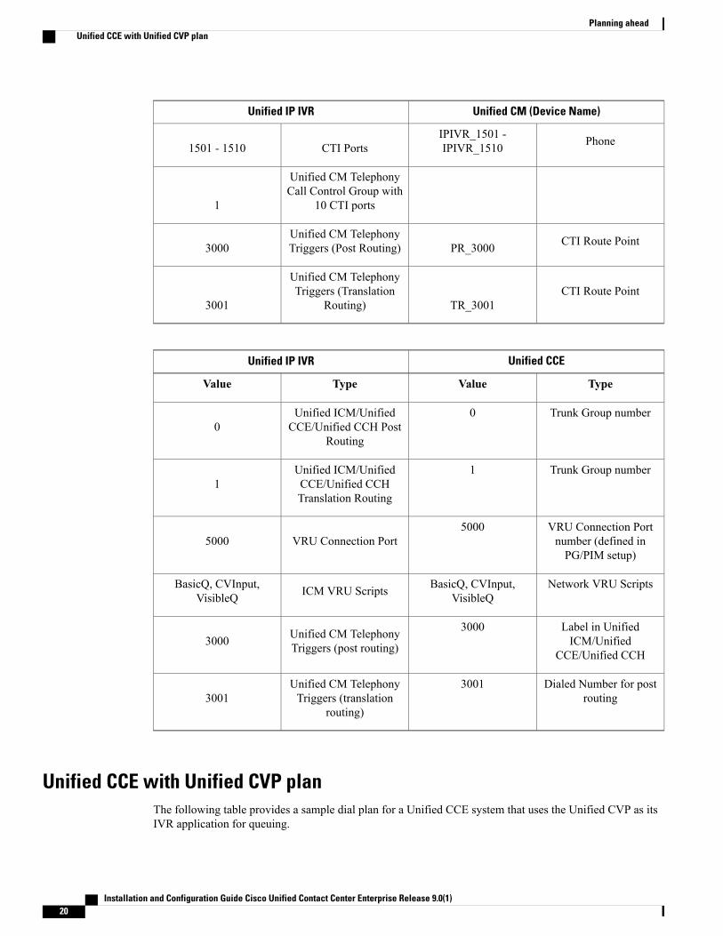
Unified CCE with Unified IP IVR sample planThe following tables provide an abbreviated sample dial plan for a Unified CCE system that is using theUnified IP IVR as its IVR application for queuing. The first table shows the configuration of the Unified IPIVR with the Unified CM. The second table shows the configuration of the Unified IP IVR with the UnifiedCCE. The values used in the tables are just samples, but you can see where configuration values need to bethe same or similar across the applications.
Unified CM (Device Name)Unified IP IVR
TypeValueTypeValue
Installation and Configuration Guide Cisco Unified Contact Center Enterprise Release 9.0(1) 19
Unified CM (Device Name)Unified IP IVR
PhoneIPIVR_1501 -IPIVR_1510CTI Ports1501 - 1510
Unified CM TelephonyCall Control Group with
10 CTI ports1
CTI Route PointPR_3000Unified CM TelephonyTriggers (Post Routing)3000
CTI Route PointTR_3001
Unified CM TelephonyTriggers (Translation
Routing)3001
Unified CCEUnified IP IVR
TypeValueTypeValue
Trunk Group number0Unified ICM/UnifiedCCE/Unified CCH Post
Routing0
Trunk Group number1Unified ICM/UnifiedCCE/Unified CCHTranslation Routing
1
VRU Connection Portnumber (defined inPG/PIM setup)
5000VRU Connection Port5000
Network VRU ScriptsBasicQ, CVInput,VisibleQICM VRU ScriptsBasicQ, CVInput,
VisibleQ
Label in UnifiedICM/Unified
CCE/Unified CCH
3000Unified CM TelephonyTriggers (post routing)3000
Dialed Number for postrouting
3001Unified CM TelephonyTriggers (translation
routing)3001
Unified CCE with Unified CVP planThe following table provides a sample dial plan for a Unified CCE system that uses the Unified CVP as itsIVR application for queuing.
Installation and Configuration Guide Cisco Unified Contact Center Enterprise Release 9.0(1)20
Planning aheadUnified CCE with Unified CVP plan
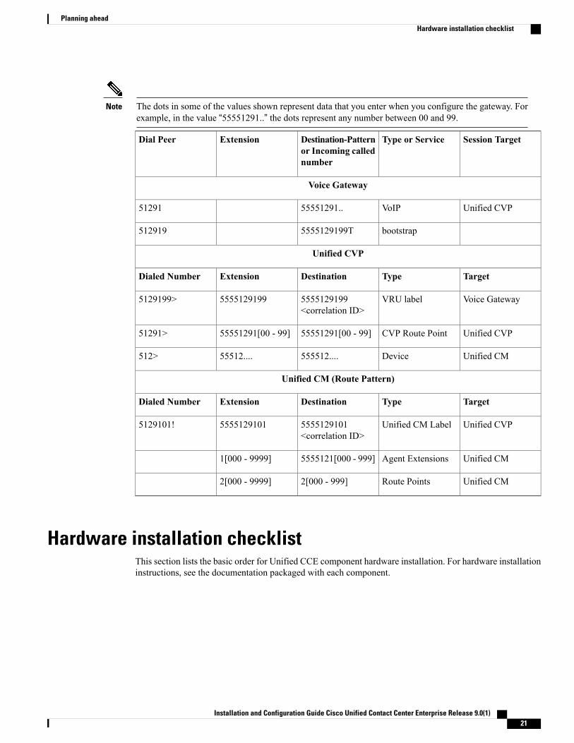
The dots in some of the values shown represent data that you enter when you configure the gateway. Forexample, in the value “55551291..” the dots represent any number between 00 and 99.
Note
Session TargetType or ServiceDestination-Patternor Incoming callednumber
ExtensionDial Peer
Voice Gateway
Unified CVPVoIP55551291..51291
bootstrap5555129199T512919
Unified CVP
TargetTypeDestinationExtensionDialed Number
Voice GatewayVRU label5555129199<correlation ID>
55551291995129199>
Unified CVPCVP Route Point55551291[00 - 99]55551291[00 - 99]51291>
Unified CMDevice555512....55512....512>
Unified CM (Route Pattern)
TargetTypeDestinationExtensionDialed Number
Unified CVPUnified CM Label5555129101<correlation ID>
55551291015129101!
Unified CMAgent Extensions5555121[000 - 999]1[000 - 9999]
Unified CMRoute Points2[000 - 999]2[000 - 9999]
Hardware installation checklistThis section lists the basic order for Unified CCE component hardware installation. For hardware installationinstructions, see the documentation packaged with each component.
Installation and Configuration Guide Cisco Unified Contact Center Enterprise Release 9.0(1) 21
Planning aheadHardware installation checklist
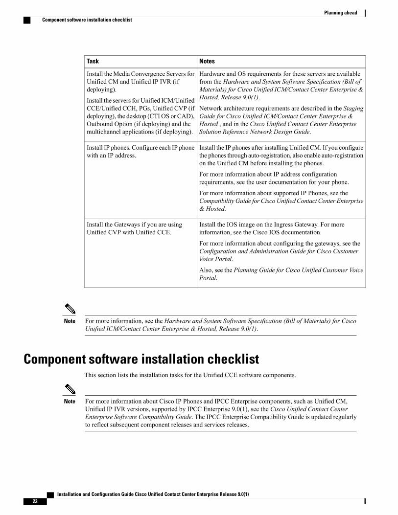
NotesTask
Hardware and OS requirements for these servers are availablefrom the Hardware and System Software Specification (Bill ofMaterials) for Cisco Unified ICM/Contact Center Enterprise &Hosted, Release 9.0(1).
Network architecture requirements are described in the StagingGuide for Cisco Unified ICM/Contact Center Enterprise &Hosted , and in the Cisco Unified Contact Center EnterpriseSolution Reference Network Design Guide.
Install theMedia Convergence Servers forUnified CM and Unified IP IVR (ifdeploying).
Install the servers for Unified ICM/UnifiedCCE/Unified CCH, PGs, Unified CVP (ifdeploying), the desktop (CTI OS or CAD),Outbound Option (if deploying) and themultichannel applications (if deploying).
Install the IP phones after installing Unified CM. If you configurethe phones through auto-registration, also enable auto-registrationon the Unified CM before installing the phones.
For more information about IP address configurationrequirements, see the user documentation for your phone.
For more information about supported IP Phones, see theCompatibility Guide for CiscoUnified Contact Center Enterprise& Hosted.
Install IP phones. Configure each IP phonewith an IP address.
Install the IOS image on the Ingress Gateway. For moreinformation, see the Cisco IOS documentation.
For more information about configuring the gateways, see theConfiguration and Administration Guide for Cisco CustomerVoice Portal.
Also, see the Planning Guide for Cisco Unified Customer VoicePortal.
Install the Gateways if you are usingUnified CVP with Unified CCE.
For more information, see the Hardware and System Software Specification (Bill of Materials) for CiscoUnified ICM/Contact Center Enterprise & Hosted, Release 9.0(1).
Note
Component software installation checklistThis section lists the installation tasks for the Unified CCE software components.
For more information about Cisco IP Phones and IPCC Enterprise components, such as Unified CM,Unified IP IVR versions, supported by IPCC Enterprise 9.0(1), see the Cisco Unified Contact CenterEnterprise Software Compatibility Guide. The IPCC Enterprise Compatibility Guide is updated regularlyto reflect subsequent component releases and services releases.
Note
Installation and Configuration Guide Cisco Unified Contact Center Enterprise Release 9.0(1)22
Planning aheadComponent software installation checklist

Once the hostname of a server has been set, a change to the hostname of any server in the system is notsupported.
Note
Unified CCE Installation NotesUnified CCE InstallationPrerequisites
Task
See Installation and configurationof Unified CommunicationsManager for Cisco Unified ContactCenter Enterprise in this book.Also see the Installation Guide forCisco Unified CommunicationsManager.
There are no Unified CCE-specificinstallation prerequisites forUnified CM.
1. Install Unified CM.
See Installation and configurationof Cisco Unified IP IVR for CiscoUnified Contact Center Enterprisein this book, and the Cisco UnifiedContact Center ExpressInstallation Guide. Be sure toselect the ICM option during theinstallation process.
Prior to installing Unified IP IVRyou must install and configure theUnified CM and check your phoneconfiguration in Unified CMAdministration.
2. Install Unified IP IVR (if youare not installing Unified CVP).
See Installation and configurationof Unified ICM, Unified CCE &Unified CCH in this book.
If you are deploying the OutboundOption, be sure to enable OutboundOption during setup of the UnifiedICM/ Unified CCE/Unified CCHLogger component.
Install Unified CM. Install UnifiedIP IVR if your Unified CCE usesUnified IP IVR for queuing.
3. Install Unified ICM/UnifiedCCE/ Unified CCH, including theRouter, Logger, andAdministration& Data Server.
The Unified CM and Unified IPIVR can use the same UCCESystem PG (you must configure aPIM for each on the PG).
You must configure the PG beforeinstalling it.
4. Install the UCCE System PG (ifusing Unified IP IVR) or the VRUPG and Unified CM PG (if usingUnified CVP).
Install the JTAPI client on theUCCE System PG if using theUnified IP IVR. Install the clienton the Unified CM PG if using theUnified CVP.
Before installing the JTAPI Client,you must configure the PG.
5. Install the JTAPI Client on theUCCE System PG or the UnifiedCM PG.
See Chapter 6 for instructions.Before setting up theMR PG usingthe Peripheral Gateway Setup Tool,you must configure it in theUnified ICM/Unified CCE/UnifiedCCH Configuration Manager.
6. Install the Media Routing PG(MR PG) if deployingMultichannel options and/orOutbound Option.
Installation and Configuration Guide Cisco Unified Contact Center Enterprise Release 9.0(1) 23
Planning aheadComponent software installation checklist

Unified CCE Installation NotesUnified CCE InstallationPrerequisites
Task
If you are deploying a Unified CCElaboratory system, you can installall Unified CVP components on asinglemachine and youmust installall components at the same time.
If you are deploying a Unified CCEproduction system, you can installindividual components on differentmachines. To maximizeperformance, do not install theVoice Browser or Call Server onthe Media Server, to which youcopy System Media Files.
Install the Unified CM. On theUnified CM, you must configurethe Unified CVPVoice Browser asa Gateway.
Install the Unified ICM/UnifiedCCE/Unified CCH and configureand set up the PG containing theVRU PIMs.
7. Install the Unified CVP (if youare not installing Unified IP IVR).
The CTI Server is a UnifiedICM/Unified CCE/Unified CCHcomponent that allows an externalCTI application to communicatewith a PG. The CTI Server is partof the Cisco Enterprise CTIproduct.
You must install the CTI Server onthe samemachine as the PeripheralGateway
Install and configure the UnifiedCM.
Install and configure UnifiedICM/Contact Center Enterprise.
Install and configure the UnifiedIP IVR or Unified CVP.
8. Install CTI Server.
See the Cisco CAD InstallationGuide or the CTI OS SystemManager's Guide.
Install CTI Server
Prior to installing agent/supervisordesktops, you must install andconfigure all other non-optionalUnified CCE software.
9. Install CTI OS or Cisco AgentDesktop software.
See the Installation and SystemAdministration Guide for CiscoInteraction Manager.
Install and configure UnifiedICM/Contact Center Enterprise &Hosted.
10. Optionally, install themultichannel applications.
Enable Outbound Option duringthe setup of the UnifiedICM/CCE/CCH Loggercomponent.
You must install the Unified CM,Unified ICM/Unified CCE/UnifiedCCH, and CTI Server before youinstall the Outbound Option.
11. Optionally, install OutboundOption.
See the Installation Guide forCisco Unified Contact CenterManagement Portal.
Install Unified ICM/CCE/CCH.12. Optionally, install UnifiedCCMP
Installation and Configuration Guide Cisco Unified Contact Center Enterprise Release 9.0(1)24
Planning aheadComponent software installation checklist
If you install the Unified CCE on a multi-lingual version of Windows 2008 R2, you must run the MUIlanguage pack to install localized Script Editor user interfaces.
Note
For more information about installing the Unified CCE components, see the following documents:
• Installing Cisco Unified Communications Manager Guide
• Cisco Unified Contact Center Express Installation Guide (for Unified IP IVR installation)
• Installation and Upgrade Guide for Cisco Unified Customer Voice PortalAlso, see the Planning Guide for Cisco Unified Customer Voice Portal.
• Installation Guide for Cisco Unified ICM/Contact Center Enterprise & Hosted
• CTI OS System Manager's Guide for Cisco Unified ICM/CCE & Hosted
• Installation Guide: Cisco Desktop Product Suite
Related Topics
Script Editor Localization, on page 125
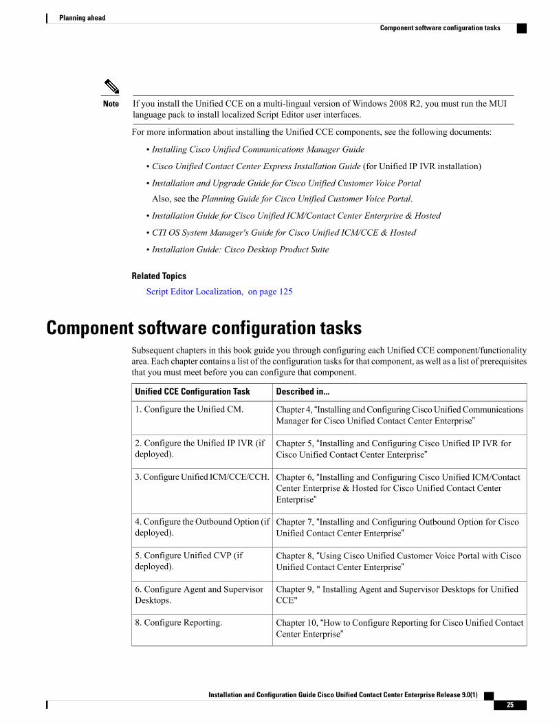
Component software configuration tasksSubsequent chapters in this book guide you through configuring each Unified CCE component/functionalityarea. Each chapter contains a list of the configuration tasks for that component, as well as a list of prerequisitesthat you must meet before you can configure that component.
Described in...Unified CCE Configuration Task
Chapter 4, “Installing and Configuring CiscoUnified CommunicationsManager for Cisco Unified Contact Center Enterprise”
1. Configure the Unified CM.
Chapter 5, “Installing and Configuring Cisco Unified IP IVR forCisco Unified Contact Center Enterprise”
2. Configure the Unified IP IVR (ifdeployed).
Chapter 6, “Installing and Configuring Cisco Unified ICM/ContactCenter Enterprise & Hosted for Cisco Unified Contact CenterEnterprise”
3. ConfigureUnified ICM/CCE/CCH.
Chapter 7, “Installing and Configuring Outbound Option for CiscoUnified Contact Center Enterprise”
4. Configure the Outbound Option (ifdeployed).
Chapter 8, “Using Cisco Unified Customer Voice Portal with CiscoUnified Contact Center Enterprise”
5. Configure Unified CVP (ifdeployed).
Chapter 9, " Installing Agent and Supervisor Desktops for UnifiedCCE"
6. Configure Agent and SupervisorDesktops.
Chapter 10, “How to Configure Reporting for Cisco Unified ContactCenter Enterprise”
8. Configure Reporting.
Installation and Configuration Guide Cisco Unified Contact Center Enterprise Release 9.0(1) 25
Planning aheadComponent software configuration tasks

Installation and Configuration Guide Cisco Unified Contact Center Enterprise Release 9.0(1)26
Planning aheadComponent software configuration tasks
C H A P T E R 4Installation and configuration of UnifiedCommunications Manager for Cisco UnifiedContact Center Enterprise
This chapter describes how to install and configure Cisco Unified Communications Manager (Unified CM)for the Unified CCE system.
• Unified CM, page 27
• Unified CM installation tasks, page 28
• Unified CM configuration tasks, page 28
• Unified CM Administration utility, page 29
• Configure IP Phones on Unified CM, page 29
• Set configuration on agent IP phone, page 30
• Unified CM Extension Mobility feature, page 30
• Configure CTI route point, page 31
• Configure CTI port, page 31
• Configure users for phones, Unified CM PG, and Unified IP IVR, page 32
• Configure Unified CM Telephony information for Unified CCX, page 33
• Configure Unified CM for Unified CVP, page 34
• Recovery number for failovers, page 35
• Call Search Space in Unified CM, page 35
Unified CMThe Unified CM provides features for which organizations have traditionally used PBX systems. The UnifiedCM uses open standards, such as TCP/IP, Session Initiation Protocol (SIP), H.323 standards (for packet-basedmultimedia communications systems), andMedia Gateway Control Protocol (MGCP). The Unified CM allows
Installation and Configuration Guide Cisco Unified Contact Center Enterprise Release 9.0(1) 27
deployment of voice applications and the integration of telephony systems with Intranet applications. Youmust install the Unified CM software on the Cisco Media Convergence Server (MCS).
The Unified CM takes care of the switching requirements of the Unified CCE system. It usesMicrosoft InternetInformation Server (IIS) to allow remote administration with a standard Web browser, and it provides thebasic services required for IP telephones, such as mapping IP addresses to specific devices and extensions,and managing Cisco Voice Gateways.
The Unified CM supports JTAPI for deploying Unified IP IVR and other applications. Telephony applicationswritten to the JTAPI specification can gain the cross-platform benefits of Java.
For more information, see the following documentation:
• Installing Cisco Unified Communications Manager
• Cisco Unified Communications Manager Administration Guide
• Cisco Unified Communications Manager Bulk Administration Tool Guide
• Cisco Unified Communications Manager Features and Services Guide
Unified CM installation tasksTo install the Unified CM, see Installing Cisco Unified Communications Manager. There are no UnifiedCCE-specific installation prerequisites or instructions for the Unified CM.
After you install Unified CM and before you configure Unified CM for Unified CCE, ensure that:
• A Unified CM instance is created on the Unified CM server
• All Unified CM services and third-party services required by Unified CM are running
• The BAT Tool is installed on the Unified CM
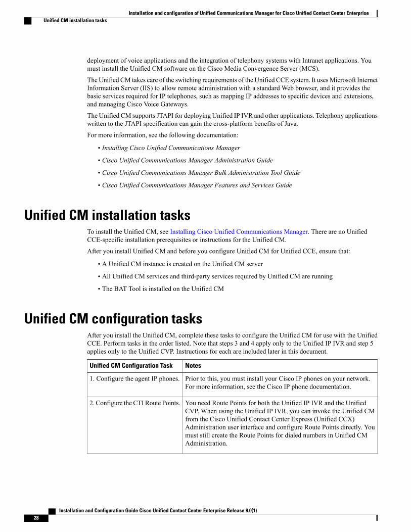
Unified CM configuration tasksAfter you install the Unified CM, complete these tasks to configure the Unified CM for use with the UnifiedCCE. Perform tasks in the order listed. Note that steps 3 and 4 apply only to the Unified IP IVR and step 5applies only to the Unified CVP. Instructions for each are included later in this document.
NotesUnified CM Configuration Task
Prior to this, you must install your Cisco IP phones on your network.For more information, see the Cisco IP phone documentation.
1. Configure the agent IP phones.
You need Route Points for both the Unified IP IVR and the UnifiedCVP. When using the Unified IP IVR, you can invoke the Unified CMfrom the Cisco Unified Contact Center Express (Unified CCX)Administration user interface and configure Route Points directly. Youmust still create the Route Points for dialed numbers in Unified CMAdministration.
2. Configure the CTI Route Points.
Installation and Configuration Guide Cisco Unified Contact Center Enterprise Release 9.0(1)28
Installation and configuration of Unified Communications Manager for Cisco Unified Contact Center EnterpriseUnified CM installation tasks

NotesUnified CM Configuration Task
For Unified IP IVR only.
You can configure Call Control Ports directly in the Unified CCXAdministration interface; you do not need to configure them in UnifiedCM.
3. Configure the Call ControlPorts.
For Unified IP IVR only.
Create one account to associate with the phones and PGs, and oneaccount to associate with Unified IP IVR and the CTI Ports.When usingUnified IP IVR, you can invoke the Unified CM from the Unified CCXAdministration user interface using the Unified CM user ID andpassword. Then you can create users and assign them as Unified IP IVRusers.
4. Create user accounts andassociate them with the JTAPIphones, Route Points, and Ports.
For Unified CVP only.
The Unified CVP documentation provides detailed instructions on howto configure Unified CM to work with Unified CVP. The instructionsvary depending on whether you are using the SIP or the H.323 protocol.
5. Add the Unified Presence Proxyserver, create SIP trunks, and addroute patterns.
Unified CM Administration utilityYou complete most Unified CM configuration tasks from the Unified CMAdministration utility. Unified CMAdministration is installed on each Unified CM server. To access Unified CM Administration in a Webbrowser, enter http://<Unified CM_servername>/ccmadmin.
Configure IP Phones on Unified CMTo function with the Unified CM, you must register each Cisco IP phone in your Unified CCE system andconfigure it within the Unified CM Administration database.
There are three different ways of doing this:
• Manual configuration: In manual configuration, each agent IP phone is configured individually. Thisdocument describes the manual configuration method.
• Auto-registration: Auto-registration allows you to automatically add a Cisco IP Phone to the UnifiedCM database when you connect the phone to your IP telephony network. During auto-registration, theUnified CM assigns the next available sequential directory number to the phone. In many cases, youmight not want to use auto-registration; for example, if you want to assign a specific directory numberto a phone. The procedure for setting up auto-registration is described in the Cisco UnifiedCommunications Manager Administration Guide.
• Bulk configuration: The Unified CMBulk Administration Tool lets you add, modify, and delete multipleCisco IP Phones in batch mode. Procedures for using the Bulk Administration Tool are not describedin this guide. For more information, see the Bulk Administration Tool Guide for Cisco UnifiedCommunications Manager.
Installation and Configuration Guide Cisco Unified Contact Center Enterprise Release 9.0(1) 29
Installation and configuration of Unified Communications Manager for Cisco Unified Contact Center EnterpriseUnified CM Administration utility

To manually configure agent IP phones on the Unified CM, perform the following steps for each agent IPPhone in your Unified CCE system:
Procedure
Step 1 In Unified CM Administration, select Device > Phone.Step 2 On the Find and List Phones page, click Add New.Step 3 On the Add a New Phone page, select the model of Cisco IP phone you are configuring from the Phone Type
drop-down list, and click Next.Step 4 On the Phone Configuration page, select the device protocol from the drop-down list (either SCCP or SIP),
and click Next.The next Phone Configuration page has many options to complete. The Unified CM Administration onlineHelp is the best source for information to use for this page. When you are finished, click Save.
A message appears that states that the phone was added to the database. To add a directory number to thisphone, click one of the line links, such as Line [1] - Add a new DN, in the Association Information pane thatappears on the left side of the window. Then continue by adding the directory number configuration settings.Note that the directory number is the agent's ID for logging in to the phone. If you use Outbound Option, setCall Waiting to On; otherwise, set it to Off.
Step 5 Create additional phones, as necessary.
Set configuration on agent IP phoneYou must set the configuration on each agent IP phone so that it can locate and connect to the Unified CM.To set the necessary configuration, on each agent IP phone in your Unified CCE system, complete the followingsteps:
Procedure
Step 1 Press Settings.Step 2 Press **# to unlock the configuration.Step 3 Select Settings > Network Configuration > Select.Step 4 Set Alternative TFTP to Yes.Step 5 Press Save and then press Exit.Step 6 Power cycle the phone. If you are using power plugs, pull the cord out of the phone and put it back in again.
If you are using inline power, disconnect and then reconnect the network cable.
Unified CM Extension Mobility featureUnified CM provides an Extension Mobility feature that lets users access their Cisco IP phone configuration,including line appearances, services, and speed dials, from other Cisco IP phones. If you enable Extension
Installation and Configuration Guide Cisco Unified Contact Center Enterprise Release 9.0(1)30
Installation and configuration of Unified Communications Manager for Cisco Unified Contact Center EnterpriseSet configuration on agent IP phone
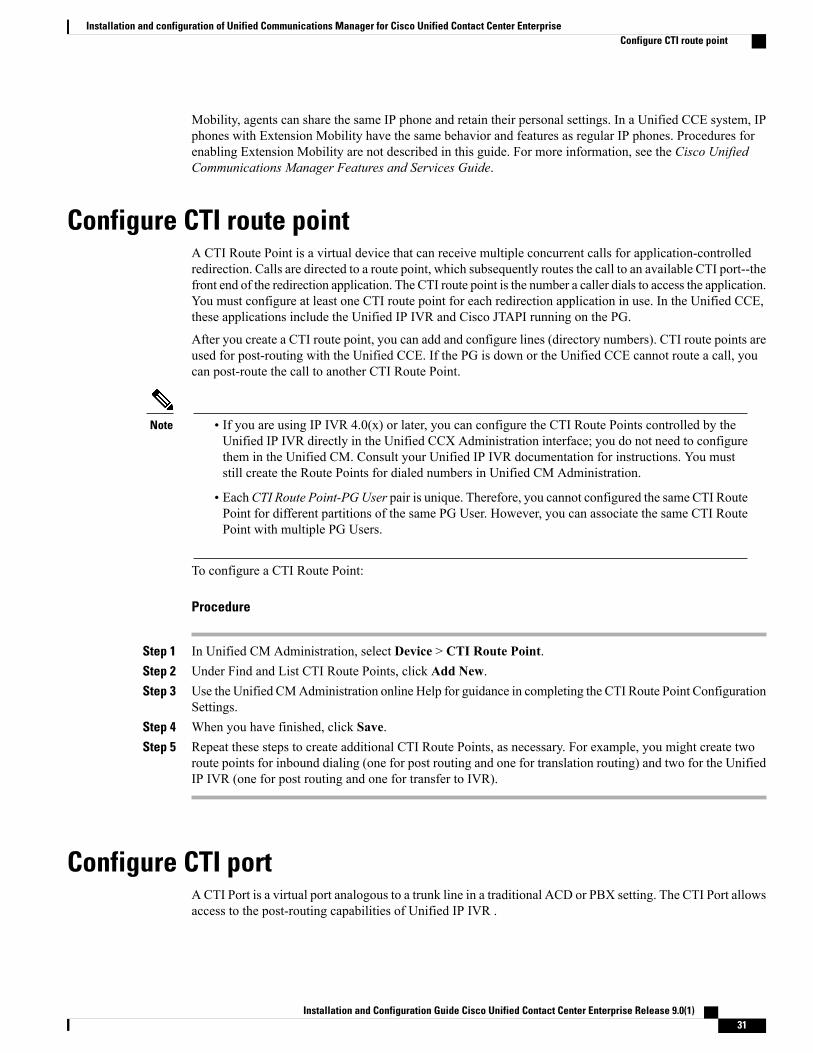
Mobility, agents can share the same IP phone and retain their personal settings. In a Unified CCE system, IPphones with Extension Mobility have the same behavior and features as regular IP phones. Procedures forenabling Extension Mobility are not described in this guide. For more information, see the Cisco UnifiedCommunications Manager Features and Services Guide.
Configure CTI route pointA CTI Route Point is a virtual device that can receive multiple concurrent calls for application-controlledredirection. Calls are directed to a route point, which subsequently routes the call to an available CTI port--thefront end of the redirection application. The CTI route point is the number a caller dials to access the application.You must configure at least one CTI route point for each redirection application in use. In the Unified CCE,these applications include the Unified IP IVR and Cisco JTAPI running on the PG.
After you create a CTI route point, you can add and configure lines (directory numbers). CTI route points areused for post-routing with the Unified CCE. If the PG is down or the Unified CCE cannot route a call, youcan post-route the call to another CTI Route Point.
Note • If you are using IP IVR 4.0(x) or later, you can configure the CTI Route Points controlled by theUnified IP IVR directly in the Unified CCX Administration interface; you do not need to configurethem in the Unified CM. Consult your Unified IP IVR documentation for instructions. You muststill create the Route Points for dialed numbers in Unified CM Administration.
• EachCTI Route Point-PGUser pair is unique. Therefore, you cannot configured the same CTI RoutePoint for different partitions of the same PG User. However, you can associate the same CTI RoutePoint with multiple PG Users.
To configure a CTI Route Point:
Procedure
Step 1 In Unified CM Administration, select Device > CTI Route Point.Step 2 Under Find and List CTI Route Points, click Add New.Step 3 Use the Unified CMAdministration online Help for guidance in completing the CTI Route Point Configuration
Settings.Step 4 When you have finished, click Save.Step 5 Repeat these steps to create additional CTI Route Points, as necessary. For example, you might create two
route points for inbound dialing (one for post routing and one for translation routing) and two for the UnifiedIP IVR (one for post routing and one for transfer to IVR).
Configure CTI portACTI Port is a virtual port analogous to a trunk line in a traditional ACD or PBX setting. The CTI Port allowsaccess to the post-routing capabilities of Unified IP IVR .
Installation and Configuration Guide Cisco Unified Contact Center Enterprise Release 9.0(1) 31
Installation and configuration of Unified Communications Manager for Cisco Unified Contact Center EnterpriseConfigure CTI route point

The number of ports you configure is determined by your needs and available licenses. To accept or placecalls, the JTAPI subsystem requires one CTI port device for each call to be managed simultaneously.
Procedure
Step 1 In Unified CM Administration, select Device > Phone.Step 2 Click Add New.Step 3 From Phone Type, select CTI Port. Click Next.Step 4 In Device Name, enter a unique name for the device.Step 5 From Device Pool, select Default.
Use the Unified CMAdministration online Help for guidance on the remaining fields. Ensure that CallWaitingis OFF.
Step 6 Click Save. Amessage appears confirming that the directory number was assigned to the current device. ClickOK.
Step 7 Repeat the above steps to create additional port groups, as necessary.
Configure users for phones, Unified CM PG, and Unified IP IVRThe Unified CM supports JTAPI for deploying telephony applications. JTAPI gives the Unified CCE accessto the Unified CM directory. JTAPI uses the directory to determine which Unified CCE devices it has theprivilege to control.
You must associate a user account with each JTAPI device. For the Unified CCE, you must create a JTAPIuser for
• the connection to Unified ICME/Unified CCE/CCH (the Unified CM PG), and
• the connection to Unified IP IVR (if deployed).
Instructions for installing the JTAPI Client on the Unified CM PG follow later in Chapter 6, “Installing andConfiguring Unified ICM/CCE/CCH for Unified CCE.”
Procedure
Step 1 In Unified CM Administration, select User Management > Application User. The User Information pageopens.
Step 2 Enter a first and last name for the user.Step 3 In User ID, enter the User ID for the PG user.Step 4 In Password, enter a password. Re-enter it in Confirm Password.Step 5 In PIN, enter an IP phone password (at least five characters). Re-enter it in Confirm PIN.
Installation and Configuration Guide Cisco Unified Contact Center Enterprise Release 9.0(1)32
Installation and configuration of Unified Communications Manager for Cisco Unified Contact Center EnterpriseConfigure users for phones, Unified CM PG, and Unified IP IVR

Note • Record the user names and passwords that you create for the JTAPI users. You need to supplythese when you configure A) Unified CM connectivity for the Unified CM PG; B) the UnifiedIP IVR user in Unified CCX Administration.
• Ensure that you add the user to the Standard CTI Enabled user group. To add a user to theStandard CTI Enabled user group, see the section "Adding Users to the Standard CTI UserGroups" at http://www.cisco.com/en/US/docs/voice_ip_comm/cucimoc/7_1/english/release/cucimocReleaseNote.html#wp61406.
• If the phone of the user is a Cisco Unified IP Phone 9900, 8900, or 6900 series model, you mustalso add the user to the Standard CTI Allow Control of Phones supporting Connected Xfer andconf user group.
Step 6 Click Save.Step 7 Bring up the profile for the user you just created. Select User Management > Application User, click Find,
then click on the link for the user you just created in the User ID column.Step 8 Under Device Information, click Device Association.Step 9 Click Find.
All the Device names and extensions display.Step 10 Select all of the devices this user controls.Step 11 Click Save Selected/Changes.Step 12 Repeat the above steps to create additional JTAPI users as necessary.
Related Topics
Installation and configuration of Unified ICM, Unified CCE & Unified CCH, on page 57
Configure Unified CM Telephony information for Unified CCXThe Unified CMTelephony client is installed in the background after you configure the Unified CMTelephonyuser. The Unified CM Telephony client runs silently and verifies that the right version and the right client areinstalled.
Procedure
Step 1 From the Unified CCX Administration menu bar, choose System > Unified CM Configuration.The Cisco Unified CM Configuration Web page opens.
Step 2 Scroll down to Unified CM Telephony Subsystem—Unified CM Telephony Provider Configurationsection and reconfigure the Unified CM Telephony information using the following fields:
DescriptionField
Unified CM Telephony Subsystem—Unified CM Telephony Provider Configuration
Installation and Configuration Guide Cisco Unified Contact Center Enterprise Release 9.0(1) 33
Installation and configuration of Unified Communications Manager for Cisco Unified Contact Center EnterpriseConfigure Unified CM Telephony information for Unified CCX

DescriptionField
Lists the CTI Managers selected by the Unified CCX user. Select therequired entry and move to the opposite list box using the right and leftarrows. Arrange the order of the selected entries using the up and downarrows.
If you deselect CTI Managers from the Selected list box, aMicrosoft IE or Mozilla Firefox window pops up informing youabout the (list of) deselected CTI Managers.
Note
Selected CTI Managers
Lists the CTI Managers in the cluster. Move to the opposite list box usingthe right and left arrows.
Available CTI Managers
Cluster Wide Parameters
The syntax of the User ID is: <userprefix>_<nodeid>
For example, if you set this field to cti_user, then the User ID for Node 1will be cti_user_1. This is a mandatory field.
User Prefix
Password you defined for the User ID in Unified CM.
If a CTI Manager is already selected, then the corresponding password isdisplayed in this field. This is a mandatory field.
Password
Reenter the password that you provided in the Password field. This is amandatory field.
Confirm Password
Step 3 Click the Update icon on top of the Cisco Unified CM ConfigurationWeb page or the Update button thatappears at the bottom of the Web page to save the changes.The Unified CM Configuration Web page refreshes to display the new settings. The newly selected CTIManager is now enabled. If the selected CTI Manager cannot be enabled, an error message instructs you toreselect CTI Managers.
Configure Unified CM for Unified CVPWhether you plan to use Session Initiation Protocol (SIP) or H323 gateway with your Unified CCE system,you need to configure Unified CM so that it works with Unified CVP.
Installation and Configuration Guide Cisco Unified Contact Center Enterprise Release 9.0(1)34
Installation and configuration of Unified Communications Manager for Cisco Unified Contact Center EnterpriseConfigure Unified CM for Unified CVP

Procedure
Step 1 The SIP trunk or the H323 gateway that refers to the Unified CVP to which you want to send the call. Configurethe SIP trunk to the SIP Proxy Server (after configuring the SIP Proxy Server) or to the Unified CVP CallServer if you are not using a SIP Proxy.
Step 2 Add call routing (route patterns) to send the call from Unified CVP; for example, ring tone, playback dialpatterns and ICM route table calls. The route pattern must match the label you are using to send the call toUnified CVP. Append “!” at the end of the route pattern to accommodate the correlation ID.
Step 3 Configure the Network VRU in Unified ICME/Unified CCE/Unified CCH.Step 4 Point the Route Pattern to the SIP trunk or H.323 gateway.
Recovery number for failoversYou can set up your system with a recovery number for failover situations. For example, you might forwardcalls to voice mail. You might also decide to forward calls to another CTI Route Point or dialed number thatsends the call to a special recovery script on the system.
After you determine an appropriate recovery number for your system, configure Call Forward No Answerand Call Forward Busy on the CTI Route Points for the Unified CM PG to point to this recovery number.
Also, configure the Call Forward on Busy (CFB) option on your phones to point to this number as well. Youcan use the Unified CM Bulk Administration Tool to do this for a group of phones, or you can configure eachline individually using the Unified CM Administration Web pages. For more information about Unified CCEfault tolerance, see the Cisco Unified Contact Center Enterprise Design Guide.
Call Search Space in Unified CMThe Call Search Space (CSS) used for transfer defaults to the callers's (not the agent's) CSS. Using the defaults,calls that invoke the redirect operation using an unexpected CSS might not have access to the destination'spartition in Unified CM, resulting in a dropped call.
The redirect operation is invoked by the following:
• Agents who initiate single-step transfer from their desktop client
• Unified CCE Dialer in CCE 7.1 or above
• Third-party CTI integrations that invoke the Deflect API of the CTI Server interface.
This is most likely to be seen as a day two issue or after a recent partition/CSS change in the Unified CMconfiguration.
The “UseRedirectAddressSearchSpace” registry key controls which CSS is used.UseRedirectAddressSearchSpace can be set to 0, 1, or 3 where:
• DEFAULT_SEARCH_SPACE = 0
• CALLINGADDRESS_SEARCH_SPACE = 1
Installation and Configuration Guide Cisco Unified Contact Center Enterprise Release 9.0(1) 35
Installation and configuration of Unified Communications Manager for Cisco Unified Contact Center EnterpriseRecovery number for failovers

• ADDRESS_SEARCH_SPACE = 2
Installation and Configuration Guide Cisco Unified Contact Center Enterprise Release 9.0(1)36
Installation and configuration of Unified Communications Manager for Cisco Unified Contact Center EnterpriseCall Search Space in Unified CM
C H A P T E R 5Installation and configuration of Cisco UnifiedIP IVR for Cisco Unified Contact Center Enterprise
This chapter describes how to install and configure the Unified IP IVR for the Unified CCE in both productionand laboratory environments. Follow the instructions in this chapter if you are using the Unified IP IVR (asopposed to the Unified CVP) for queuing in your Unified CCE system. (If you are deploying Unified CVPinstead of Unified IP IVR , see Cisco Unified Customer Voice Portal and Cisco Unified Contact CenterEnterprise.)
• Unified IP IVR, page 38
• Installation of Unified IP IVR for Unified CCE, page 38
• Unified IP IVR installation prerequisites, page 39
• Unified IP IVR configuration tasks, page 39
• Access to Cisco Administration utility, page 40
• Configure Unified CM Telephony Provider for Unified IP IVR, page 40
• Configure Unified CM Telephony Call Control Group, page 41
• Configure Unified ICM subsystem, page 46
• Configure VRU script, page 48
• Translation routing and post routing, page 49
• Configure Unified IP IVR for Unified ICME/Unified CCE/Unified CCH translation routing, page 50
• Configure Unified IP IVR for Unified ICME/Unified CCE/Unified CCH post routing, page 52
• Configure Unified ICME post-routing application, page 53
• Start Unified CCX Engine, page 55
• Resynchronize Unified CM Telephony data, page 55
• Resynchronize Cisco JTAPI Client, page 55
• Unified ICME/Unified CCE/Unified CCH configuration for Unified IP IVR, page 56
Installation and Configuration Guide Cisco Unified Contact Center Enterprise Release 9.0(1) 37

Unified IP IVRThe Unified IP IVR is an application on the Cisco Unified Contact Center Express (Unified CCX) platform.Unified IP IVR provides Interactive Voice Response (IVR) and queuing capability in the Unified CCE system.Unified IP IVR is a multichannel (voice/data/Web) IP-enabled Interactive Voice Response solution thatprovides an open, extensible, and feature-rich foundation for the creation and delivery of IVR solutions usingInternet technology. In addition to handling traditional telephony contacts, you can create Unified IP IVRapplications to respond to HTTP requests and send email messages.
The Unified IP IVR automates the handling of calls by autonomously interacting with users. The Unified IPIVR processes user commands to facilitate command response features such as access to checking accountinformation or user-directed contact routing. The Unified IP IVR also performs prompt and collect functionsto obtain user data such as passwords or account identification. The Unified IP IVR supports Open DatabaseConnectivity (ODBC) access to Microsoft SQL Server and MSDE databases.
You can use the Unified IP IVR to extract and parse Web-based content and present the data to customersusing a telephony or HTTP interface.
The Unified IP IVR communicates with the Unified ICME/Unified CCE/Unified CCH software by way ofthe Service Control Interface (SCI) protocol.
The following Cisco documents provide additional information about the Installation and configuration tasksdescribed in this chapter:
• Cisco Unified Contact Center Express Installation Guide
• Cisco Unified Contact Center Express Administration Guide
• Getting Started with Cisco Unified IP IVR
You can access these documents from the Cisco Unified Contact Center Express Introduction Page.
Installation of Unified IP IVR for Unified CCETo install the Unified IP IV , follow the step-by-step installation instructions included in the Cisco UnifiedContact Center Express Installation Guide.
When you install Unified IP IVR for use with the Unified CCE, you must select the Unified IP IVR productpackage during installation. This installs the basic Unified IP IVR platform, which includes the basiccomponents of Unified IP IVR and the default ICM scripts. The Unified CCX installation procedure has twomain steps:
• Installation: Loads the Unified CCX software onto your system. At this time you can select thedeployment type (Unified CM and a language). After completing the installation, confirm that the ICMoption appears on the Subsystems menu of the Administration utility. If it does not, you might have tomodify the license (.lic) file.
• Server Setup: After you install Unified IP IVR, you use the Unified CCX Administration Web utilityto perform the initial system setup. This enables the specific Unified CCX components that run on aparticular server.
Installing the Unified IP IVR provides the basic components of the application and default ICM scripts.
Installation and Configuration Guide Cisco Unified Contact Center Enterprise Release 9.0(1)38
Installation and configuration of Cisco Unified IP IVR for Cisco Unified Contact Center EnterpriseUnified IP IVR
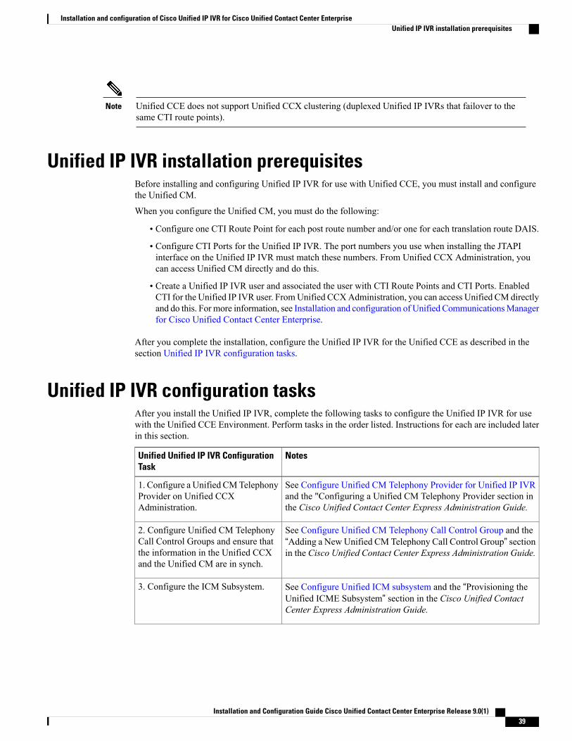
Unified CCE does not support Unified CCX clustering (duplexed Unified IP IVRs that failover to thesame CTI route points).
Note
Unified IP IVR installation prerequisitesBefore installing and configuring Unified IP IVR for use with Unified CCE, you must install and configurethe Unified CM.
When you configure the Unified CM, you must do the following:
• Configure one CTI Route Point for each post route number and/or one for each translation route DAIS.
• Configure CTI Ports for the Unified IP IVR. The port numbers you use when installing the JTAPIinterface on the Unified IP IVR must match these numbers. From Unified CCX Administration, youcan access Unified CM directly and do this.
• Create a Unified IP IVR user and associated the user with CTI Route Points and CTI Ports. EnabledCTI for the Unified IP IVR user. FromUnified CCXAdministration, you can access Unified CM directlyand do this. For more information, see Installation and configuration of Unified CommunicationsManagerfor Cisco Unified Contact Center Enterprise.
After you complete the installation, configure the Unified IP IVR for the Unified CCE as described in thesection Unified IP IVR configuration tasks.
Unified IP IVR configuration tasksAfter you install the Unified IP IVR, complete the following tasks to configure the Unified IP IVR for usewith the Unified CCE Environment. Perform tasks in the order listed. Instructions for each are included laterin this section.
NotesUnified Unified IP IVR ConfigurationTask
See Configure Unified CM Telephony Provider for Unified IP IVRand the "Configuring a Unified CM Telephony Provider section inthe Cisco Unified Contact Center Express Administration Guide.
1. Configure a Unified CMTelephonyProvider on Unified CCXAdministration.
See Configure Unified CM Telephony Call Control Group and the“Adding a New Unified CM Telephony Call Control Group” sectionin the Cisco Unified Contact Center Express Administration Guide.
2. Configure Unified CM TelephonyCall Control Groups and ensure thatthe information in the Unified CCXand the Unified CM are in synch.
See Configure Unified ICM subsystem and the “Provisioning theUnified ICME Subsystem” section in the Cisco Unified ContactCenter Express Administration Guide.
3. Configure the ICM Subsystem.
Installation and Configuration Guide Cisco Unified Contact Center Enterprise Release 9.0(1) 39
Installation and configuration of Cisco Unified IP IVR for Cisco Unified Contact Center EnterpriseUnified IP IVR installation prerequisites

NotesUnified Unified IP IVR ConfigurationTask
See Configure VRU script and the "Configuring Unified ICMEVRUScripts" section in the Cisco Cisco Unified Contact Center ExpressAdministration Guide.
4. Create and upload VRU scripts.
See Translation routing and post routing and the sections aboutconfiguring post and translation routing in theCisco Unified ContactCenter Express Administration Guide.
5. Configure the Unified IP IVR forUnified CCE Post and/or TranslationRouting.
See Start Unified CCX Engine “Starting, Stopping, and RestartingCisco Unified CCX Services” section in the Cisco Unified ContactCenter Express Administration Guide.
6. Start the Unified CCX Engine.
See Resynchronize Unified CM Telephony data and the CiscoUnified Contact Center Express Administration Guide.
7. Resynchronize the Unified CMTelephony Data
See Resynchronize Cisco JTAPI Client and theCiscoUnified ContactCenter Express Administration Guide.
8. Resynchronize the Cisco JTAPIClient
You can find the information you need to perform the preceding tasks in theCisco Unified CCX AdministrationGuide and briefly described in the following sections.
Access to Cisco Administration utilityYou perform most of the tasks in this section from the Cisco Unified CCX Administration utility, which isinstalled on your Unified IP IVR server. Access Unified CCXAdministration at: http://<ipivr_servername>/appadmin.
Configure Unified CM Telephony Provider for Unified IP IVRAfter configuring Unified CM, you need to configure a Unified CM Telephony Provider for your Unified IPIVR. This user is identified in the Unified IP IVR software when you configure the Unified CM TelephonyProvider.
Procedure
Step 1 From the Unified CCX Administration menu bar, choose System > Unified CM Configuration.The Unified CM ConfigurationWeb page opens.
Step 2 On the Web page specify the following:a) Selected or Available CTI Managers: Select the required entry and move to the opposite list box using
the right and left arrows.b) User Prefix: The syntax of the User ID is: <userprefix>_<nodeid>. For example, if you set this field to
cti_user, then the User ID for Node 1 is cti_user_1.
Installation and Configuration Guide Cisco Unified Contact Center Enterprise Release 9.0(1)40
Installation and configuration of Cisco Unified IP IVR for Cisco Unified Contact Center EnterpriseAccess to Cisco Administration utility

c) Password: The password you defined for the User ID in Unified CM.
Step 3 Click OK and the Unified CM Configuration Web page refreshes to display the new settings.A Microsoft IE window pops up to confirm the newly selected CTI Manager.
Step 4 Click OK in the Microsoft IE window.The newly selected CTI Manager is now enabled.
The Unified CM Telephony Providers area of the Unified CM Telephony Configuration Web page is aread-only page that displays the latest configured information. To view the configured information for theUnified CM Telephony Provider, from the Unified CCX Administration menu bar, select Subsystems >Unified CM Telephony > Unified CM Telephony Provider.
Configure Unified CM Telephony Call Control GroupA Call Control Group is a group of access points into the Unified CCE telephone network. You use CallControl Groups to associate Cisco Unified IP IVR applications, translation routes, post routes, busy treatments,and ring no answer treatments with a Unified CCE trunk group.
A CTI port is a virtual device that is used by Unified CM applications, including the Unified IP IVR, to createvirtual lines. You configure CTI ports through Unified CM Administration. The CTI ports in a Call ControlGroup must have consecutive directory numbers. For example, if you want twenty CTI ports in a particularCall Control group, and the first number is 9001, the rest of the ports are 9002 through 9020. With twentyports, the Unified IP IVR can handle twenty calls at a time.
If your Unified CCE deployment uses the System PG, your Group IDs must:
• be an odd number
• be unique for all Unified IP IVR handled by a System PG
For example, if a System PG handles multiple Unified IP IVRs and each Unified IP IVR has one CTI PortGroup, then the CTI Port Group ID for the first Unified IP IVR should be 1, the port group ID for the secondUnified IP IVR should be 3, and so on.
Procedure
Step 1 From the Unified CCX Administration menu bar, choose Subsystems > Unified CM Telephony > CallControl Group.The Cisco Unified CM Telephony Call Control Group ConfigurationWeb page opens displaying theexisting Unified CM Telephony Call Control Group information, if any.
Step 2 Click Add New icon that appears in the tool bar in the upper, left corner of the window or the Add Newbutton that appears at the bottom of the window to create a new CTI port.The Cisco Unified CM Telephony Call Control Group ConfigurationWeb page opens.
Step 3 Use this Web page to specify the following information:
Installation and Configuration Guide Cisco Unified Contact Center Enterprise Release 9.0(1) 41
Installation and configuration of Cisco Unified IP IVR for Cisco Unified Contact Center EnterpriseConfigure Unified CM Telephony Call Control Group
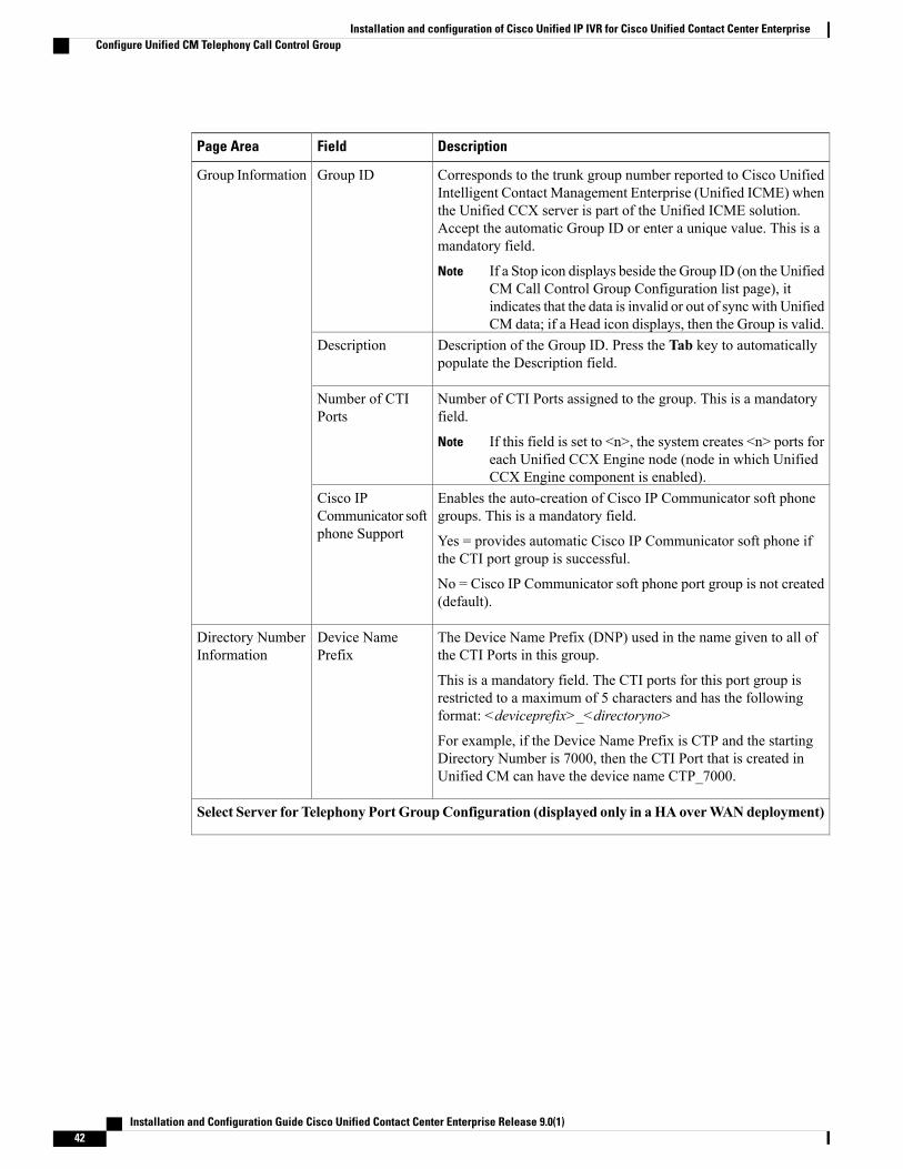
DescriptionFieldPage Area
Corresponds to the trunk group number reported to Cisco UnifiedIntelligent Contact Management Enterprise (Unified ICME) whenthe Unified CCX server is part of the Unified ICME solution.Accept the automatic Group ID or enter a unique value. This is amandatory field.
If a Stop icon displays beside the Group ID (on the UnifiedCM Call Control Group Configuration list page), itindicates that the data is invalid or out of sync with UnifiedCM data; if a Head icon displays, then the Group is valid.
Note
Group IDGroup Information
Description of the Group ID. Press the Tab key to automaticallypopulate the Description field.
Description
Number of CTI Ports assigned to the group. This is a mandatoryfield.
If this field is set to <n>, the system creates <n> ports foreach Unified CCX Engine node (node in which UnifiedCCX Engine component is enabled).
Note
Number of CTIPorts
Enables the auto-creation of Cisco IP Communicator soft phonegroups. This is a mandatory field.
Yes = provides automatic Cisco IP Communicator soft phone ifthe CTI port group is successful.
No = Cisco IP Communicator soft phone port group is not created(default).
Cisco IPCommunicator softphone Support
The Device Name Prefix (DNP) used in the name given to all ofthe CTI Ports in this group.
This is a mandatory field. The CTI ports for this port group isrestricted to a maximum of 5 characters and has the followingformat: <deviceprefix>_<directoryno>
For example, if the Device Name Prefix is CTP and the startingDirectory Number is 7000, then the CTI Port that is created inUnified CM can have the device name CTP_7000.
Device NamePrefix
Directory NumberInformation
Select Server for Telephony Port GroupConfiguration (displayed only in aHA overWANdeployment)
Installation and Configuration Guide Cisco Unified Contact Center Enterprise Release 9.0(1)42
Installation and configuration of Cisco Unified IP IVR for Cisco Unified Contact Center EnterpriseConfigure Unified CM Telephony Call Control Group

DescriptionFieldPage Area
This field only appears in a HA over WAN deployment.
In a HA over WAN setup, you need to configure directoryinformation along with Unified CM-specific information for theports in each node. This field displays the different Unified CCXnodes that are available in a HA over WAN deployment in adrop-down list.
After you select a node, you can view the node-specificconfiguration details for the node. You can configure the data forthe selected node. Click Update to save the updated configurationinformation. For more information about HA over WAN, see theCisco Unified CCX High Availability User Guide.
In case of LAN deployment, this field does not appear asthe same configuration data is applicable for both thenodes in the cluster.
Note
Select Server
Installation and Configuration Guide Cisco Unified Contact Center Enterprise Release 9.0(1) 43
Installation and configuration of Cisco Unified IP IVR for Cisco Unified Contact Center EnterpriseConfigure Unified CM Telephony Call Control Group

DescriptionFieldPage Area
A unique phone number. The value can include numeric charactersand special characters (#) and (*). This is a mandatory field.
The specified number of ports are created starting from the valuespecified in this field.
The Directory Number that you enter can appear in more than onepartition.
When a pattern is used as a Directory Number, the phonedisplay and the caller ID display on the dialed phonecontains characters other than digits. To avoid this, providea value for Display (Internal Caller ID), Line Text Label,and External Phone Number Mask.
Note
Starting DirectoryNumber
Directory NumberInformation
Set of common characteristics for devices, such as region, date/timegroup, softkey template, andMLPP information to which you wantto assign this phone. Click theAdd Device Pools button to specifythe number of CTI ports for a selected device pool.
Device Pool
A collection of partitions that are searched to determine how adialed number should be routed. The calling search space for thedevice and the calling search space for the directory number getused together. The directory number calling search space takesprecedence over the device calling search space.
For more information, see the Cisco Unified CommunicationsManager System Guide.
DNCalling SearchSpace
The CiscoUnified Communications phone location setting specifiesthe total bandwidth that is available for calls to and from thislocation. A location setting of HUB_NONEmeans that the locationfeature does not keep track of the bandwidth that this Cisco UnifiedCommunications phone consumes.
Location
The CiscoUnified Communications phone location setting specifiesthe total bandwidth that is available for calls to and from thislocation. A location setting of HUB_NONEmeans that the locationfeature does not keep track of the bandwidth that this Cisco UnifiedCommunications phone consumes.
Partition
Advanced Directory Number Information (only available if you click Show More)
Installation and Configuration Guide Cisco Unified Contact Center Enterprise Release 9.0(1)44
Installation and configuration of Cisco Unified IP IVR for Cisco Unified Contact Center EnterpriseConfigure Unified CM Telephony Call Control Group
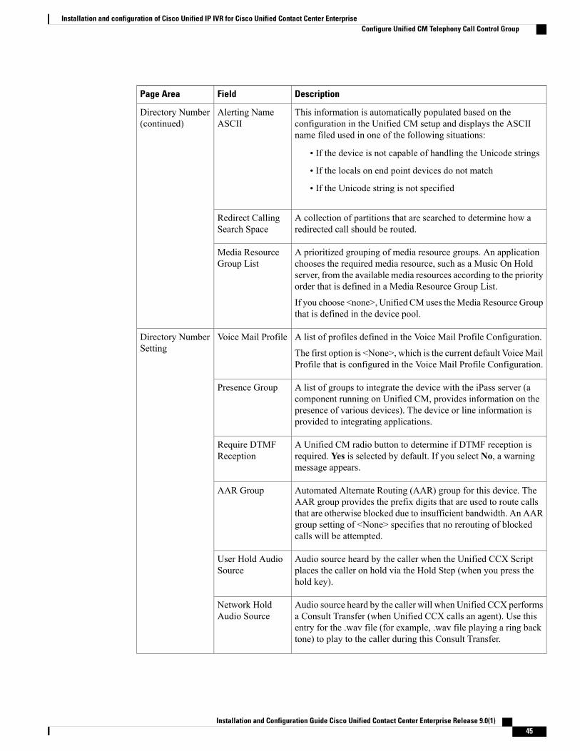
DescriptionFieldPage Area
This information is automatically populated based on theconfiguration in the Unified CM setup and displays the ASCIIname filed used in one of the following situations:
• If the device is not capable of handling the Unicode strings
• If the locals on end point devices do not match
• If the Unicode string is not specified
Alerting NameASCII
Directory Number(continued)
A collection of partitions that are searched to determine how aredirected call should be routed.
Redirect CallingSearch Space
A prioritized grouping of media resource groups. An applicationchooses the required media resource, such as a Music On Holdserver, from the available media resources according to the priorityorder that is defined in a Media Resource Group List.
If you choose <none>, Unified CMuses theMedia Resource Groupthat is defined in the device pool.
Media ResourceGroup List
A list of profiles defined in the Voice Mail Profile Configuration.
The first option is <None>, which is the current default VoiceMailProfile that is configured in the Voice Mail Profile Configuration.
Voice Mail ProfileDirectory NumberSetting
A list of groups to integrate the device with the iPass server (acomponent running on Unified CM, provides information on thepresence of various devices). The device or line information isprovided to integrating applications.
Presence Group
A Unified CM radio button to determine if DTMF reception isrequired. Yes is selected by default. If you select No, a warningmessage appears.
Require DTMFReception
Automated Alternate Routing (AAR) group for this device. TheAAR group provides the prefix digits that are used to route callsthat are otherwise blocked due to insufficient bandwidth. An AARgroup setting of <None> specifies that no rerouting of blockedcalls will be attempted.
AAR Group
Audio source heard by the caller when the Unified CCX Scriptplaces the caller on hold via the Hold Step (when you press thehold key).
User Hold AudioSource
Audio source heard by the caller will when Unified CCX performsa Consult Transfer (when Unified CCX calls an agent). Use thisentry for the .wav file (for example, .wav file playing a ring backtone) to play to the caller during this Consult Transfer.
Network HoldAudio Source
Installation and Configuration Guide Cisco Unified Contact Center Enterprise Release 9.0(1) 45
Installation and configuration of Cisco Unified IP IVR for Cisco Unified Contact Center EnterpriseConfigure Unified CM Telephony Call Control Group

DescriptionFieldPage Area
The number that can be dialed to answer calls to this directorynumber in the specified partition.
Call Pickup GroupCall Forward andPickup Settings
Use a maximum of 30 alphanumeric characters. Typically, use theuser name or the directory number (if using the directory number,the person receiving the call may not see the proper identity of thecaller).
Leave this field blank to have the system display the extension.
Display
Phone number (or mask) that is used to send Caller ID informationwhen a call is placed from this line.
You can enter a maximum of 30 number and X characters. The Xcharacters represent the directory number and must appear at theend of the pattern. For example, if you specify a mask of972813XXXX, an external call from extension 1234 displays acaller ID number of 9728131234.
External PhoneNumber Mask
Step 4 When finished, click Update to create the specified number of CTI ports starting with <Starting DirectoryNumber>. After creating the CTI ports, the respective CTI ports are associated to the Unified CM Telephonyuser configured in the Unified CM Telephony Provider page.
Step 5 Press the Tab key to automatically populate the Description field.Step 6 Click Add.
TheUnified CMTelephonyCall Control GroupConfiguration summaryWeb page opens. The call controlgroup you added appears in the Group ID column.
Step 7 As necessary, repeat these steps to create additional port groups and associate them with CTI ports.
Configure Unified ICM subsystemThe Unified ICM subsystem of the Unified IP IVR system allows the Unified IP IVR software to interactwith the Unified ICME/Unified CCE/Unified CCH software. Unified ICME/Unified CCE/Unified CCHsoftware provides a central control system that directs calls to various human and automated systems. UnifiedICME routing scripts can direct calls based on various criteria, such as time of day or the availability ofsubsystems. The Unified ICM subsystem is the queuing engine for Unified CCE, which includes Unified IPIVR.
Procedure
Step 1 In Unified CCX Administration, select Subsystems > ICM > General. The Unified ICM ConfigurationWeb page opens.
Step 2 Use this Web page to specify the following fields:
Installation and Configuration Guide Cisco Unified Contact Center Enterprise Release 9.0(1)46
Installation and configuration of Cisco Unified IP IVR for Cisco Unified Contact Center EnterpriseConfigure Unified ICM subsystem
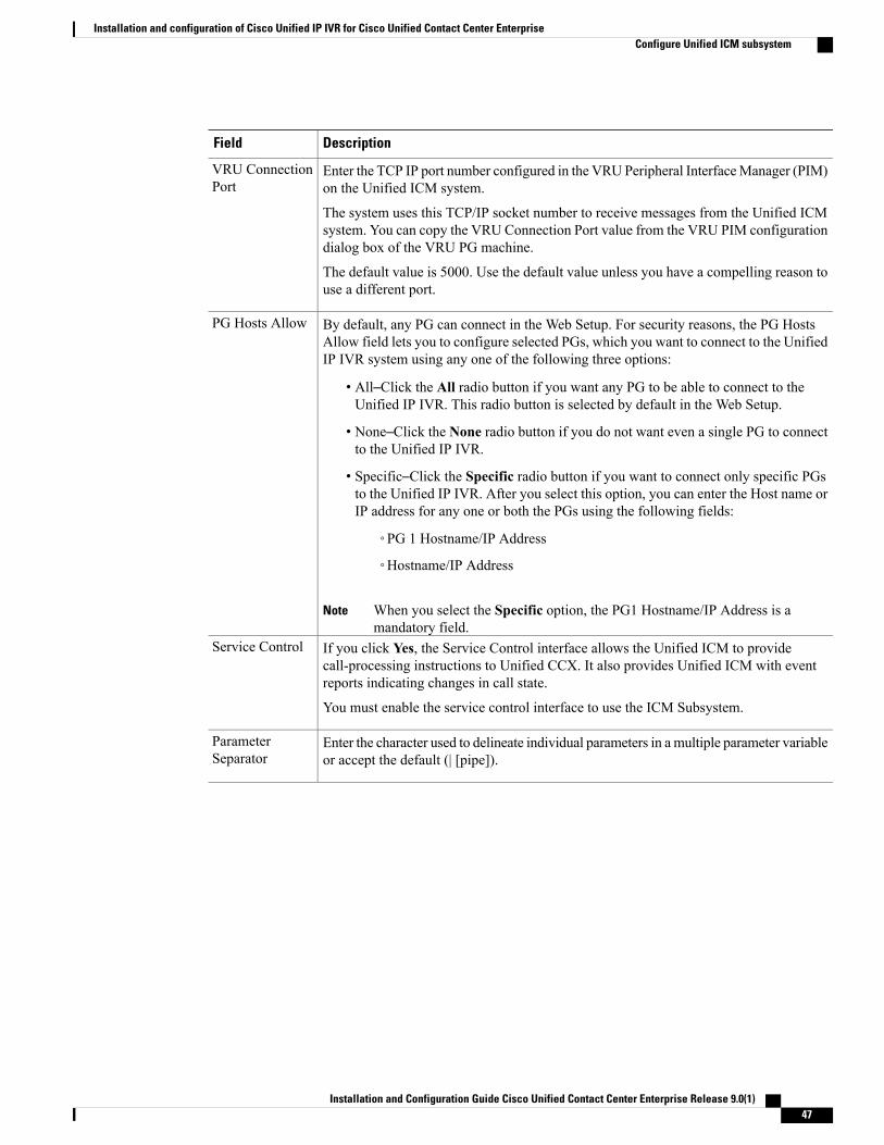
DescriptionField
Enter the TCP IP port number configured in the VRU Peripheral InterfaceManager (PIM)on the Unified ICM system.
The system uses this TCP/IP socket number to receive messages from the Unified ICMsystem. You can copy the VRU Connection Port value from the VRU PIM configurationdialog box of the VRU PG machine.
The default value is 5000. Use the default value unless you have a compelling reason touse a different port.
VRU ConnectionPort
By default, any PG can connect in the Web Setup. For security reasons, the PG HostsAllow field lets you to configure selected PGs, which you want to connect to the UnifiedIP IVR system using any one of the following three options:
• All–Click the All radio button if you want any PG to be able to connect to theUnified IP IVR. This radio button is selected by default in the Web Setup.
• None–Click the None radio button if you do not want even a single PG to connectto the Unified IP IVR.
• Specific–Click the Specific radio button if you want to connect only specific PGsto the Unified IP IVR. After you select this option, you can enter the Host name orIP address for any one or both the PGs using the following fields:
◦PG 1 Hostname/IP Address
◦Hostname/IP Address
When you select the Specific option, the PG1 Hostname/IP Address is amandatory field.
Note
PG Hosts Allow
If you click Yes, the Service Control interface allows the Unified ICM to providecall-processing instructions to Unified CCX. It also provides Unified ICM with eventreports indicating changes in call state.
You must enable the service control interface to use the ICM Subsystem.
Service Control
Enter the character used to delineate individual parameters in amultiple parameter variableor accept the default (| [pipe]).
ParameterSeparator
Installation and Configuration Guide Cisco Unified Contact Center Enterprise Release 9.0(1) 47
Installation and configuration of Cisco Unified IP IVR for Cisco Unified Contact Center EnterpriseConfigure Unified ICM subsystem

DescriptionField
Select the required variables to pass call-related information by selecting the check box.
The following expanded call variables are available on the Unified ICM subsystem:
• Task ID–Task ID that handles the current call.
• Media–IDMedia ID that handles the current call.
• Last Redirected Address–Transient part ID of the call.
• Arrival Type–Arrival type of the call.
• Session Handled–Boolean flag that the Unified ICME software or a Set ContactInfo step with a Handled flag step sets to indicate whether the session is handled.
The Unified CCX automatically sets the flag whenever a call is connectedto an agent.
Note
• VRU Script Name–Script name to run on the PreConnect feature.All scripts under the default directory are listed in the drop-down list ofthe Script field in the Cisco Script Application Configuration page.
Note
• Config Param–Parameters for the VRU scripts on the PreConnect feature.
Additional VRUCall Information
Step 3 Click Update.The configuration information is added to the system.
Configure VRU scriptThe Unified CCE uses Voice Response Unit (VRU) scripts to handle interactions with contacts. These scriptsare loaded as applications on the Unified CCX Engine.
The Unified IP IVR comes with some default scripts that are loaded as applications on the Unified CCXEngine. You also can create your own VRU scripts using the Cisco Unified CCX Editor. When configuringthe Unified CCE, you can configure any VRU scripts that you plan to use. You must upload the scripts to theUnified IP IVR Repository so that the scripts are available whenever the Unified CCE sends a Run VRUScript request to Unified IP IVR.
Procedure
Step 1 In Unified CCX Administration menu bar, select Subsystems > ICM > ICM VRU Scripts. The ICM VRUScripts Web page opens displaying the list of VRUs.
Step 2 Click the Add New icon or button in the ICM VRU ScriptsWeb page.Step 3 Another ICM VRU ScriptsWeb page opens where you can specify values for the following fields:
Enter a name for the VRU script that you want to add in the Script Name field.
Select the Unified CCX script that you want to associate with the VRU script from the Script drop-down list.
Installation and Configuration Guide Cisco Unified Contact Center Enterprise Release 9.0(1)48
Installation and configuration of Cisco Unified IP IVR for Cisco Unified Contact Center EnterpriseConfigure VRU script
Step 4 ClickAdd. The second ICMVRUScriptsWeb page closes, and the name of the VRU script you added appearsin the first ICM VRU ScriptsWeb page.Repeat the steps mentioned to add any additional VRU scripts.
Translation routing and post routingDepending on how you choose to do call routing, you must configure your Unified CCE deployment for postrouting and possibly translation routing.
Translation routing
In translation routing, the Unified CCE receives the call instead of the Unified IP IVR. Because the UnifiedIP IVR does not receive the call first, it does not run an initial script. After receiving the call, the Unified CCEruns a script. You must configure Unified CCE translation routing when you use the Unified IP IVR as aqueue point for a Unified CCE solution in which calls are expected to be routed by the VRU PG to UnifiedIP IVR. The call attributes are reported as part of a configured translation-route on Unified CCE.
The Unified CCE routing scripts can direct calls based on various criteria, such as time of day or the availabilityof subsystems. Unified CCE routing scripts use the following four commands to interact with Unified IP IVR:
• Connect connects the call. The Unified CCE sends the connect message with a label to instruct UnifiedIP IVR where to direct the call.
• Release hangs up the call.
• Run VRU Script runs a VRU script on Unified IP IVR.
• Cancel cancels the VRU script that is currently running.
Post routing
In post routing, the Unified IP IVR receives calls directly from the Unified CM. The Unified CM sends thecall to the post routing route point on the Unified IP IVR. The Unified IP IVR searches the designated portgroup for a free CTI port and accepts the call. If there is no free port, the caller hears ringing until there is afree port to take the call.
If you configure the route point to run an initial application, such as a script to welcome the caller and collectan account number, the Unified IP IVR runs that script, notifies the Unified CCE about the call, and waits forfurther instructions. If you did not configure an initial application, the Unified IP IVR just informs the UnifiedCCE. The Unified CCE runs a routing script after being notified of the call. The Unified IP IVR systemresponds to the commands from the Unified CCE until it signals that the call is complete.
For example, the Unified CCE routing script could send a Run VRU Script request to the Unified IP IVR,instructing the Unified IP IVR to run a VRU script that plays music and thanks the caller for their patience.When an agent becomes available, the Unified CCE sends a Cancel request and the Unified IP IVR stopsrunning the current VRU script. The Unified CCE then sends a Connect command with a Normal label thatindicates the extension of the free agent. The Unified IP IVR system routes the call to the agent indicated onthe label.
Installation and Configuration Guide Cisco Unified Contact Center Enterprise Release 9.0(1) 49
Installation and configuration of Cisco Unified IP IVR for Cisco Unified Contact Center EnterpriseTranslation routing and post routing

The Unified CCE does not support post routing within a Unified CCE deployment. However, post routingis supported between a child Unified CCE and its parent in an Unified IPCC Gateway deployment. Formore information, see the Unified IPCC Gateway documentation.
Note
Configure Unified IP IVR for Unified ICME/Unified CCE/UnifiedCCH translation routing
You must configure Unified ICME translation-routing applications when the Unified CCX server is used asa queue point for a Unified CCX solution in which calls are expected to be routed by the Unified ICME tothe Unified CCX server. The call attributes are reported as part of a configured translation-route on the UnifiedICME.
Before you can configure a translation routing application, you must first upload the VRU scripts that theapplication needs.
Note
To configure the Unified ICME translation-routing application, you must perform the following tasks.
1 Add a Unified ICME translation-routing application.
In addition to configuring general information such as name and ID, you must specify the script on whichthe Unified ICME translation-routing application is based.
2 Add a Unified CM Telephony trigger to the Unified ICME translation-routing application.
The Unified ICME translation-routing application is invoked by a Unified CM Telephony trigger, anddoes not support HTTP triggers.
Procedure
Step 1 In Unified CCX Administration, select Applications > Application Management.The Application ManagementWeb page opens displaying the details of existing applications, if any.
Step 2 Click Add New icon that appears in the tool bar in the upper, left corner of the window or the Add Newbutton that appears at the bottom of the window.The Add a New ApplicationWeb page opens.
Step 3 From the Application Type drop-down list, select Unified ICME Translation Routing.The Unified ICME Translation-Routing configurationWeb page opens.
Step 4 Use this Web page to specify the following fields.DescriptionField
A name for the application.Name
Use the Tab key to automatically populate this field.Description
Installation and Configuration Guide Cisco Unified Contact Center Enterprise Release 9.0(1)50
Installation and configuration of Cisco Unified IP IVR for Cisco Unified Contact Center EnterpriseConfigure Unified IP IVR for Unified ICME/Unified CCE/Unified CCH translation routing

DescriptionField
Accept the automatically-generated ID, or enter a unique ID.
This field corresponds to the service identifier of the call reported to the UnifiedICME and configured in the Unified ICME translation route.
ID
The maximum amount of simultaneous sessions (instances) that the applicationcan handle.
The limit for the maximum number of simultaneous remote monitoringsessions is 16, but the actual number depends on your system's CPU andmemory resources. Entering a number that is too high can result inunacceptable system performance.
Note
Maximum Number ofSessions
(Radio button) Accept Yes (the default).Enabled
The maximum amount of time (in seconds) that the system waits to invoke theapplication before rejecting a contact.
Timeout (in seconds)
(Drop-down list) Choose a script to run to route a call to a default treatment if thefollowing occurs:
• System error
• Request by Unified ICME
Default Script
Step 5 In the Name field, enter the name of the script on which the Unified CCE translation routing is based.Step 6 Press the Tab key to automatically populate the Description field.Step 7 In the ID field, accept the ID, or enter a unique ID. This field corresponds to the service identifier of the call
reported to the Unified ICME and configured in the Unified ICME translation route.Step 8 In Maximum Number of Sessions, enter the maximum number of sessions that the application can handle
simultaneously.Step 9 In the Enabled field, accept the default radio button Yes.Step 10 In the Timeout (in secs) field, enter a value (in seconds). This value is the maximum amount of time the system
waits to invoke the application before rejecting a contact.Step 11 From the Default Script drop-down list, choose the script that runs if a system error occurs, or if instructed
by the Unified ICME/Unified CCE/Unified CCH to route to the default treatment.Step 12 Click Add. A message displays confirming the operation was successfully executed.Step 13 Click OK.Step 14 Click Add New Trigger. The Add a New Trigger page opens.Step 15 From Trigger Type drop-down list, select Unified CM/Unified CME Telephony, and then click Next.Step 16 In Unified CCX Administration, select Subsystems > Unified CM Telephony.Step 17 On the Unified CM Telephony Configuration navigation bar, click the Unified CM Telephony Triggers
hyperlink.The Unified CM Telephony Trigger Configuration summary Web page opens.
Step 18 Click the Add a New Unified CM Telephony Trigger hyperlink.
Installation and Configuration Guide Cisco Unified Contact Center Enterprise Release 9.0(1) 51
Installation and configuration of Cisco Unified IP IVR for Cisco Unified Contact Center EnterpriseConfigure Unified IP IVR for Unified ICME/Unified CCE/Unified CCH translation routing

The Unified CM Telephony Trigger Configuration Web page opens. Complete the fields on this page. Formore information, see the online Help.
Step 19 Click Add. The Unified CM Telephony Trigger Configuration summary Web page opens, and displays thenew Unified CM Telephony trigger.
For more information about adding applications and triggers to the Unified IP IVR see the online Help or theCisco Unified Contact Center Express Administration Guide.
Configure Unified IP IVR for Unified ICME/Unified CCE/UnifiedCCH post routing
To configure the Unified IP IVR for post routing, you must first add a Unified ICME/Unified CCE/UnifiedCCH post routing application and then assign a JTAPI trigger to this application.
Before you can configure a Unified ICME/Unified CCE/Unified CCH routing application, you must firstupload any VRU scripts that the application needs.
Note
Procedure
Step 1 In Unified CCX Administration, select Applications > Application Management.Step 2 Click Add a New Application.Step 3 From the Application Type drop-down list, select Unified ICME Post-Routing.Step 4 In the Name field, enter the name of the script on which the post routing is based.Step 5 Press the Tab key to automatically populate the Description field.Step 6 In the ID field, accept the ID, or enter a unique ID. This field corresponds to the service identifier of the call
reported to the Unified ICME/Unified CCE/Unified CCH and configured in the translation route.Step 7 In Maximum Number of Sessions, enter the maximum number of sessions that the application can handle
simultaneously.Step 8 In the Enabled field, accept the default radio button Yes.Step 9 In the Timeout (in secs) field, enter a value (in seconds). This value is the maximum amount of time the system
waits to invoke the application before rejecting a contact.Step 10 From the Default Script drop-down list, choose the script that runs if a system error occurs, or if instructed
by the Unified CCE to route to the default treatment.Step 11 Click Add. A message appears confirming the operation was successfully executed.Step 12 Click OK.Step 13 Click Add New Trigger. The Add a New JTAPI Trigger page opens.Step 14 From Trigger Type drop-down list, select Unified CM/Unified CME Telephony, and then click Next.Step 15 In Unified CCX Administration, select Subsystems > Unified CM Telephony.Step 16 On the Unified CM Telephony Configuration navigation bar, click the Unified CM Telephony Triggers
hyperlink.
Installation and Configuration Guide Cisco Unified Contact Center Enterprise Release 9.0(1)52
Installation and configuration of Cisco Unified IP IVR for Cisco Unified Contact Center EnterpriseConfigure Unified IP IVR for Unified ICME/Unified CCE/Unified CCH post routing

The Unified CM Telephony Trigger Configuration summary Web page opens.
Step 17 Click the Add a New Unified CM Telephony Trigger hyperlink.The Unified CM Telephony Trigger Configuration Web page opens. Complete the fields on this page. Formore information, see the online Help.
Step 18 Click Add. The Unified CM Telephony Trigger Configuration summary Web page opens, and displays thenew Unified CM Telephony trigger.
For more information about adding applications and triggers to Unified IP IVR see the online Help or theCisco Unified Contact Center Express Administration Guide.
Configure Unified ICME post-routing applicationThe Unified IP IVR system uses these applications to receive calls directly from the Unified CM, which sendsthe call to the post-routing route point on the Unified CCX system.
Unified ICME post-routing applications use the Unified CCX server as a queue point for the Unified ICME.In Unified ICME post-routing, the Unified IP IVR system receives calls directly from the Unified CM, whichsends the call to the post-routing route point on the Unified CCX system. If you configure this route point torun an initial application, such as an application to welcome the caller and collect an account number, theUnified CCX system notifies the Unified ICME software about the call, and then waits for further instructions.If you do not configure an initial script, the Unified CCX system informs the Unified ICME software aboutthe call, but takes no other action.
After notification, the Unified ICME system runs a script, which can comprise many different call-handlingsteps, including three commands that can be sent to the Unified CCX system:
• Connect: This request is automatically sent by the Unified ICME whenever an agent is available andthe call can be connected to that agent.
• Release: This request releases the call.
• Run VRU Script: This request runs the VRU script.
To configure a Unified ICME post-routing application, you must perform the following tasks:
• Add a Unified ICME post-routing application. In addition to configuring general information such asname and ID, you must specify the script on which the Unified ICME post-routing application is based.
• Add a Unified CM Telephony trigger to the Unified ICME post-routing application. The Unified ICMEpost-routing application is invoked by a Unified CM Telephony trigger. The Unified ICME post-routingapplication does not support HTTP triggers.
To configure the Unified CCX server with the post-routing application and to add a Unified CM Telephonytrigger, complete the following steps:
Procedure
Step 1 From the Unified CCX Administration menu bar, choose Applications > Application Management.
Installation and Configuration Guide Cisco Unified Contact Center Enterprise Release 9.0(1) 53
Installation and configuration of Cisco Unified IP IVR for Cisco Unified Contact Center EnterpriseConfigure Unified ICME post-routing application
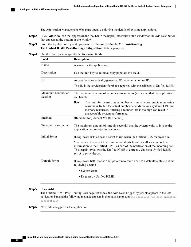
The Application Management Web page opens displaying the details of existing applications.
Step 2 ClickAdd New icon that appears in the tool bar in the upper, left corner of the window or the Add New buttonthat appears at the bottom of the window.
Step 3 From the Application Type drop-down list, choose Unified ICME Post-Routing.The Unified ICME Post-Routing configurationWeb page opens.
Step 4 Use this Web page to specify the following fields:DescriptionField
A name for the application.Name
Use the Tab key to automatically populate this field.Description
Accept the automatically-generated ID, or enter a unique ID.
This ID is the service identifier that is reported with the call back to Unified ICME.
ID
The maximum amount of simultaneous sessions (instances) that the applicationcan handle.
The limit for the maximum number of simultaneous remote monitoringsessions is 16, but the actual number depends on your system's CPU andmemory resources. Entering a number that is too high can result inunacceptable system performance.
Note
Maximum Number ofSessions
(Radio button) Accept Yes (the default).Enabled
The maximum amount of time (in seconds) that the system waits to invoke theapplication before rejecting a contact.
Timeout (in seconds)
(Drop-down list) Choose a script to run when the Unified CCX receives a call.
You can use this script to acquire initial digits from the caller and report theinformation to the Unified ICME as part of the notification of the incoming call.This capability allows the Unified ICME to correctly choose a Unified ICMEscript to serve the call.
Initial Script
(Drop-down list) Choose a script to run to route a call to a default treatment if thefollowing occurs:
• System error
• Request by Unified ICME
Default Script
Step 5 Click Add.The Unified ICME Post-Routing Web page refreshes, the Add New Trigger hyperlink appears in the leftnavigation bar, and the followingmessage appears in the status bar on top: The operation has been executed
successfully.
Step 6 Now, add a trigger for the application
Installation and Configuration Guide Cisco Unified Contact Center Enterprise Release 9.0(1)54
Installation and configuration of Cisco Unified IP IVR for Cisco Unified Contact Center EnterpriseConfigure Unified ICME post-routing application
Start Unified CCX EngineAfter completing all the Unified CCE configuration for Unified IP IVR , return to this topic to start the UnifiedCCX Engine. The subsystems do not start until the configuration of all elements is complete and valid. TheUnified CM can support more than one Unified CCX Engine.
Procedure
Step 1 Select Cisco Unified CCX Serviceability from the Navigation drop-down list box in top right corner of theUnified CCX Administration menu bar and login with Unified CCX AppAdmin credentials.
Step 2 Choose Tools > Control Center > Network Services from the Unified CCX Serviceability menu bar.Step 3 Click the Unified CCX Engine radio button below System Services and click Restart or Stop and Start.
Resynchronize Unified CM Telephony dataThis resynchronizing process ensures that the Unified CM Telephony user, the call control groups, and thetriggers match the version of Unified CM being used.
Procedure
Step 1 From the Unified CCX Administration menu bar, choose Subsystems > Cisco Unified CM Telephony >Data Resync.
Step 2 The Data Resync Web page opens after resynchronization displaying the Data Resync status of Unified CMTelephony Port Groups and Unified CM Telephony Triggers.You are now ready to provision a Unified CM Telephony trigger.
Resynchronize Cisco JTAPI ClientDuring the resynchronizing process, an additional check (effective with Cisco Unified CCX Release 5.0)ensures that the Unified CM Telephony Client (also known as the Cisco JTAPI Client) are the same betweenthe clients installed on the Unified CCX node and the Cisco JTAPI Client installer. If the Unified CCX platformdetects a mismatch, the system downloads and installs the compatible/required installer version.
Procedure
Step 1 Choose Subsystems > Cisco Unified CM Telephony > Cisco JTAPI Resync from the Unified CCXAdministration menu bar.
Step 2 The Cisco JTAPI Resync Web page opens displaying the status of Cisco JTAPI Client resynchronization.At this point, if there is an incompatible version, it automatically downloads the new client.
Installation and Configuration Guide Cisco Unified Contact Center Enterprise Release 9.0(1) 55
Installation and configuration of Cisco Unified IP IVR for Cisco Unified Contact Center EnterpriseStart Unified CCX Engine

Unified ICME/Unified CCE/Unified CCH configuration for UnifiedIP IVR
When configuring Unified ICME/Unified CCE/CCH for Unified IP IVR, note that some values must matchacross the applications.
Note the following during configuration:
• The VRU connection port number (5000) on Unified ICME/Unified CCE/Unified CCH (TheConfiguration dialog box appears to enter properties of the VRU peripheral when you configure thePIM) must match the VRU Connection port in Unified IP IVR.
• The Trunk Group peripheral number in the Unified ICME/Unified CCE/Unified CCH must match theCTI Port Group ID on Unified IP IVR.
• The Dialed Number defined in the Unified ICME/Unified CCE/ UnifiedCCH (Configuration Manager,choose Tools > List Tools > Dialed Number List) must match the Unified CM Telephony triggers inthe Unified IP IVR for translation routing.
• The VRU scripts defined in the Unified ICME/Unified CCE/Unified CCH (Configuration Manager,select Tools > List Tools > Network VRU Script List) must match the ones defined in ICM VRUScripts in Unified IP IVR.
Related Topics
VRU PG configuration and setup, on page 74Configuration of Unified ICM/CCE/CCH for Unified CCE, on page 60Configure dialed number, on page 96Configure Network VRU script, on page 107Unified CCE with Unified IP IVR sample plan, on page 19
Installation and Configuration Guide Cisco Unified Contact Center Enterprise Release 9.0(1)56
Installation and configuration of Cisco Unified IP IVR for Cisco Unified Contact Center EnterpriseUnified ICME/Unified CCE/Unified CCH configuration for Unified IP IVR

C H A P T E R 6Installation and configuration of Unified ICM,Unified CCE & Unified CCH
This chapter describes how to install and configure Cisco Unified ICM/Unified CCE/Unified CCH.
For more information about Remote Administration, see Chapter 14 of the Security Best Practices Guidefor Cisco Unified ICM/Contact Center Enterprise & Hosted, Release 9.x(y).
• Unified ICM/CCE/CCH, page 57
• Installation of Unified ICM/CCE/CCH for Unified CCE, page 59
• Configuration of Unified ICM/CCE/CCH for Unified CCE, page 60
Unified ICM/CCE/CCHUnified ICM/CCE/CCHprovides ACD functionality includingmonitoring and control of Agent State, routingand queuing of contacts, CTI capabilities, real-time data for agents and supervisors, and gathering real-timeand historical data for reporting in the Unified CCE system.
The basic Unified ICM/CCE/CCH software includes the following components: Administration & DataServer, Router, Logger, Peripheral Gateway, CTI Server, and Administration Client.
Unified ICM/CCE/CCH componentsBefore you can configure Unified ICM/CCE/CCH for use in a Unified CCE environment, you must firstinstall the following Unified ICM/CCE/CCH components.
For more information about how to install these components, see the Installation Guide for Cisco UnifiedICM/Contact Center Enterprise & Hosted.
Note
Installation and Configuration Guide Cisco Unified Contact Center Enterprise Release 9.0(1) 57

DescriptionUnified ICM/CCE/CCHComponent
TheAdministration&Data Server receives real-timemonitoring data directlyfrom the Central Controller and passes the data on to other Administration& Data Servers. Depending on its defined role, an Administration & DataServer can support the following functionality: Configuration, Real-timeand Historical Reporting, Call Detail Extraction, Call Variable, Agent Detail,and Cisco Unified Intelligence Suite (CUIS) feed. If given the proper role,an Administration & Data Server can also be the human interface to thesystem.
Administration & Data Server
TheAdministration Client is the human interface to Unified ICM/CCE/CCH.You use the Administration Client to monitor activity in the UnifiedICM/CCE/CCH system and to access the Configuration Manager tools. AnAdministration Client doesn't have its own database, but connects toAdministration & Data Servers for its configuration and real-time data.
Administration Client
The Router (along with the Logger) is the Central Controller component ofUnified ICM/CCE/CCH. The Router executes routing scripts to determinethe destination of each call. It also gathers data from the Peripheral Gatewaysand distributes monitoring data to the Administration & Data Server.
Router
The Logger is the Unified ICM/CCE/CCH component that stores the Centraldatabase.
Logger
You must create an HDS database for every Administration & Data Serverwith an HDS role.
Historical Data Server (HDS)Databases
The CTI Server is the Unified ICM/CCE/CCH component that provides aninterface between the agent desktops and the PG for Unified CM.
CTI Server
A Peripheral Gateway (PG) is the hardware platform and the logical softwareprocess that runs on the peripheral (ACD or VRU). It communicates thestatus of the peripheral to the central controller.
Peripheral Gateway
Unified ICM/CCE/CCH installation prerequisites for Unified CCEBefore installing and configuring the Unified ICM/CCE/CCH for use with the Unified CCE, youmust completethe tasks in the following table.
There are also prerequisites for installing Unified ICM/CCE/CCH on its own; that is, before you use itwith the Unified CCE. For more information, see the Installation Guide for Cisco Unified ICM/ContactCenter Enterprise & Hosted.
Note
Installation and Configuration Guide Cisco Unified Contact Center Enterprise Release 9.0(1)58
Installation and configuration of Unified ICM, Unified CCE & Unified CCHUnified ICM/CCE/CCH installation prerequisites for Unified CCE

Installation and Configuration NotesUnified ICM/CCE/CCHInstallation Prerequisites
On Unified CM Administration, you have:
• Configured one CTI Route Point for each post route number and/orone for each translation route DAIS.
• Created a Unified CMPG user and associated the user with CTI RoutePoints and CTI Ports.
• Enabled CTI for the Unified CM PG user.
Install Unified CM
On Unified IP IVR , you must have:
• Configured the VRU Port Group.
• Configured the Unified ICM Subsystem.
• Uploaded VRU Scripts.
• Specified the VRU Connection Port.
• Configured translation routing on Unified IP IVR.
If you are using the Unified CVP for queuing, you install that afteryou install the Unified ICM/CCE/CCH.
Note
Install Unified IP IVR (ifdeploying)
Related Topics
Cisco Unified Customer Voice Portal and Cisco Unified Contact Center Enterprise, on page 113
Installation of Unified ICM/CCE/CCH for Unified CCEStep-by-step installation instructions for the Unified ICM/CCE/CCH are included in the Installation Guidefor Cisco Unified ICM/Contact Center Enterprise & Hosted.When you install the Unified ICM/CCE/CCHfor use in a Unified CCE system, information in this section can help you to prepare.
When adding the Logger using the Web Setup Tool, if you deploy the Outbound Option, enable OutboundOption as described in Enable Outbound Option during Unified ICM/CCE/CCH installation.
For more information about Outbound Option, see Chapter 7 of this guide and the Outbound Option Guidefor Cisco Unified ICM/Contact Center Enterprise & Hosted.
Enable Outbound Option during Unified ICM/CCE/CCH installationOutbound Option is a Unified ICM/CCE/CCH optional feature that allows agents to make automatic outboundcalls to customers. You enable this feature when adding a Logger using the Web Setup Tool.
During the process of adding a Logger, you come to the third Add Logger page, which has three check boxes.
Installation and Configuration Guide Cisco Unified Contact Center Enterprise Release 9.0(1) 59
Installation and configuration of Unified ICM, Unified CCE & Unified CCHInstallation of Unified ICM/CCE/CCH for Unified CCE

Procedure
Step 1 Select the Enable Outbound Option box.Step 2 Click Next and continue adding the Logger.
For more information, see Installation Guide for Cisco Unified ICM/Contact Center Enterprise & Hosted.
Configuration of Unified ICM/CCE/CCH for Unified CCEAfter installation, complete the tasks described in this section to configure the Unified ICM/CCE/CCH foruse in a Unified CCE Environment.
Unified ICM/CCE/CCH configuration tasksThe following table lists the configuration tasks you require for the Unified ICM/CCE/CCH in a Unified CCEdeployment. Perform these tasks in the order listed. Instructions are included later in this chapter.
NotesUnified ICM/CCE/CCH Configuration Task
1. Configure agent desk settings.
2. Configure a Network VRU.
You must configure the PG in Configuration Managerbefore you set it up using the Peripheral Gateway SetupTool. Create two PIMs, one for Unified CM and one forUnified IP IVR.
The system PG is not supported for PrecisionRouting.
Note
3. Configure and install the UCCE System PG(if using Unified IP IVR).
You must configure the PG in Configuration Managerbefore you set it up using the Peripheral Gateway SetupTool.
4. Configure and install the VRU PG (if usingUnified CVP).
You must configure the PG in Configuration Managerbefore you set it up using the Peripheral Gateway SetupTool.
5. Configure and install the Unified CM PG (ifusing Unified CVP).
6. Install the JTAPI Client on the PG.
You create MR PGs only if you deploy Outbound Optionor the Multichannel options.
You must configure the MR PG in Configuration Managerbefore you set it up using the Peripheral Gateway SetupTool.
7. Configure and install the MR PG.
Installation and Configuration Guide Cisco Unified Contact Center Enterprise Release 9.0(1)60
Installation and configuration of Unified ICM, Unified CCE & Unified CCHConfiguration of Unified ICM/CCE/CCH for Unified CCE

NotesUnified ICM/CCE/CCH Configuration Task
8. Configure network trunk groups.
9. Configure trunk groups.
For UCCE System PG deployments only.10. Configure the Network VRU Bank.
11. Configure services.
For Precision Queue configuration, refer to PrecisionRouting Release 9.0(1).
12. Configure skill groups and PrecisionQueue.
13. Configure persons.
14. Configure agents.
15. Configure routes.
For Unified IP IVR or Unified CVP.16. Configure ECC variables.
17. Configure call types.
18. Configure dialed numbers.
Not required for UCCE System PG deployments.19. Configure device targets.
Not required for UCCE System PG deployments.20. Configure labels.
21. Configure dialed number plan
Not required for UCCE System PG deployments.22. Configure translation routes.
23. Configure VRU scripts.
24. Configure routing and administrativescripts.
Access to Configuration ManagerAll the tasks in the section “How to Configure Unified ICM/CCE/CCH for Unified CCE” are performed fromthe Configuration Manager.
Accessing the Configuration Manager: If you are using an Administration & Data Server system or anAdministration Client system, there is a “Unified CCETools” icon on the desktop after installation. Double-clickthe icon, and then select “Administration Tools”.Click the appropriate icon to access Configuration Manager.
Installation and Configuration Guide Cisco Unified Contact Center Enterprise Release 9.0(1) 61
Installation and configuration of Unified ICM, Unified CCE & Unified CCHAccess to Configuration Manager

Routing clientAUnified CCE routing client is anything that can generate a route request to the Unified CCECentral Controller(Central Controller). The Central Controller then executes a routing script and returns a routing label to therouting client. A redundant PIM is viewed as a single logical routing client, and only one side of a PIM isactive at any point in time.
The Unified CM PIM (representing the entire Unified CM cluster), Unified IP IVR, and Unified CVP PIMare routing clients. For example, in a Unified CCE deployment with one Unified CM cluster (with any numberof nodes) and two Unified IP IVRs, three routing clients are required: the Unified CMPIM and the two UnifiedIP IVR PIMs.
Bulk Configuration ToolYou can use the Bulk Configuration Tool to insert and update multiple configuration records in a singletransaction.
To access the Bulk Configuration Tool, in the Configuration Manager select Tools > Bulk Configuration.
The Bulk Configuration Tool lets you configure the following in bulk:
• Persons
• Agents
• Call types
• Dialed Numbers
• Dialed Number Plans
• Device Targets
• Labels
• Network Trunk Groups
• Network VRU Scripts
• Peripheral Targets
• Regions
• Scheduled Targets
• Services
• Skill Groups
• Trunks
• Trunk Groups
• VRU Port Maps
• Region Prefixes
• Routes
Installation and Configuration Guide Cisco Unified Contact Center Enterprise Release 9.0(1)62
Installation and configuration of Unified ICM, Unified CCE & Unified CCHRouting client

Agent Desk SettingsAgent Desk Settings associate a set of permissions or characteristics with specific agents. The settings arecomparable to Class of Service settings on a PBX or ACD. Desk settings are associated with an agent whenyou configure the agent. The desk settings are global in scope and you can apply them to any configured agenton any peripheral within a Unified ICM/CCE/CCH configuration.
Agent Desk Settings provide a profile that specifies parameters such as whether auto-answer is enabled, howlong to wait before rerouting a call for Ring No Answer, what DN to use in the rerouting, and whether reasoncodes are needed for logging out and going not-ready. You must associate each agent with an agent desksetting profile in the Unified CCE configuration. A single agent desk setting profile can be shared by manyagents. Changes made to an agent's desk setting profile while the agent is logged in are not activated until theagent logs out and logs in again.
If Agent Desk Settings are not associated with an agent, the agent is assigned the peripheral default settings,which depend on the peripheral to which the agent is assigned.
When you configure Agent Desk Settings, you specify the amount of non-active time after which an agent isautomatically logged out, whether wrap up is required following incoming and outbound calls, the amountof time allocated for wrap up, and the method used for assist and emergency calls. You also specify settingsfor the Ring No Answer feature.
About Ring No AnswerThe Ring No Answer feature, configured in Agent Desk Settings, ensures that when an agent does not answera call, the call is taken away from the agent after a specified number of seconds and re-assigned to anotheragent or requeued.
When a call is routed to an agent but the agent fails to answer the call within a configurable amount of time,the Unified CM PIM for the agent who did not answer changes that agent's state to not ready (so that the agentdoes not get more calls) and launch a route request to find another agent. Any call data is preserved and poppedonto the next agent's desktop. If no agent is available, the call can be sent back to the Unified IP IVR forqueuing treatment again. Again, all call data is preserved. The routing script for this RONA treatment shouldset the call priority to “high” so that the next available agent is selected for this caller. In the agent desk settings,you can set the RONA timer and the DN used to specify a unique call type and routing script for RONAtreatment.
This feature behaves and is configured differently depending on whether you deploy the Unified CVP orUnified IP IVR in the Unified CCE System.
The Dialed Number for Ring No Answer is peripheral-specific. Therefore, each Unified CM PG in yourdeployment must have its own set of Agent Desk Settings configured for it; you cannot use a particulardesk setting across peripherals.
Note
About Ring No Answer with Unified IP IVR
For Unified CCE systems in which you deploy the Unified IP IVR, the Ring No Answer feature ensures thatwhen an agent does not answer a call the following applies:
• The call is taken away from that agent after ringing for a configurable number of seconds and is reroutedto a different agent or placed in queue.
Installation and Configuration Guide Cisco Unified Contact Center Enterprise Release 9.0(1) 63
Installation and configuration of Unified ICM, Unified CCE & Unified CCHAgent Desk Settings

• The state of the agent who did not answer the call is changed to “Not Ready.”
Reroute a call on Ring No Answer works as follows for Unified IP IVR:
1 A routing script connects the call to an agent.
2 If the agent does not answer the phone within the Ring No Answer time set in Agent Desk Settings, theUnified CM changes the agent's state to “Not Ready” and post routes the call to Unified ICM/CCE/CCH.
3 The Unified ICM/CCE/CCH Router runs a routing script using the dialed number specified in the agentdesk setting record. The routing script associated with the DN typically looks for another agent and routesthe call to that new agent.
4 If no agents are available, the call typically is translation routed or queued to the IVR, or sent to someother queue point. Queuing treatment is restarted.
Give the call the highest priority in the queue so that the call is routed to the next available agent.Note
5 Any call data is preserved to be popped onto the agent screen. In addition, a flag is set in the database sothat Unified ICM/CCE/CCH can report on all of the occurrences of Ring No Answer.
About Ring No Answer with Unified CVP
For Unified CCE systems in which you deploy the Unified CVP, the Unified CM does not control the UnifiedCVP and cannot send an unanswered call back to the Unified CVP for re-queuing. You configure the RingNo Answer feature to only make the agent “Not Ready” when they do not answer a call, and use the UnifiedCVP Router Requery feature to re-queue the call.
As of Release 9.0, the Unified CVP deployment no longer requires that you configure the RNA timer on bothsides (Unified CVP and Unified CCE); configure Ring No Answer (RNA) timeout only in Unified CVP. Thisremoves the requirement to manually align the relevant Unified CVP and Unified CCE timer configuration.To configure RNA timeout in Unified CVP, see the Patterns for RNA timeout on outbound SIP callssection in the Unified CVP OAMP console.
Reroute a call on Ring No Answer works as follows for Unified CVP:
1 A routing script connects the call to an agent by sending a connect message to the Unified CVP. The scriptnode should have Enable Target Requery enabled. To enable this, edit the node, select Change and checkthe Enable Target Requery check box.
2 The agent's phone rings.
3 If the phone is not answered (either via the agent desktop or physically going off-hook) within the RingNo Answer time set in Agent Desk Settings, Unified ICM/CCE/CCH makes the agent unavailable, butdoes not actually change the agent state to Not Ready until the call is redirected.
4 When the Unified CVP Ring No Answer timeout expires, the Unified CVP sends an EventReport=NoAnswer message to the Router instructing it to select another target according to the routing script andsend a Connect message to Unified CVP. The target might be another agent or a VRU label to requeuethe call.
Give the call the highest priority in the queue so that the call is routed to the next available agent.Note
5 Any call data is preserved to be popped onto the second agent screen.
Installation and Configuration Guide Cisco Unified Contact Center Enterprise Release 9.0(1)64
Installation and configuration of Unified ICM, Unified CCE & Unified CCHAgent Desk Settings

In addition, a flag is set in the database so that Unified ICM/CCE/CCH can report on all of the occurrencesof Ring No Answer.
Note
6 When the call is redirected from the original agent, the agent's state changes to “Not Ready.”
About Auto Answer in a multi-line environmentIn a multi-line enabled environment, if you have selected Auto Answer on the Attributes tab of the ICMConfiguration Manager Agent Desk Settings List tool, and you are on a call on your non-ACD line, the callwill not auto-answer. However, if you turn on Unified CM Auto Answer, the call will answer.
Configure Agent Desk Settings
Procedure
Step 1 From the Configuration Manager, choose Configure ICM > Enterprise > Agent Desk Settings > AgentDesk Settings List.The Agent Desk Settings List dialog box opens.
Step 2 Click Retrieve and then Click Add.Step 3 Fill in the Attributes tab information:
Name. Enter a name for the agent desk settings that is unique within the enterprise.
Ring No Answer Time. Enter the number of seconds (between 1 and 120) that a call may ring at the agent'sstation. If you are deploying the Unified CVP, make sure this number is less than the number set for the NoAnswer Timeout for Router Requery that you set in the Unified CVP.
If you configure this timer, you do not need to configure the Unified CM Call Forward on No Answer foragent extensions in the Unified CM, unless you want them to be used when the agent is not logged in. If youset the Unified CM Call Forward No Answer time, enter a value at least 3 seconds higher than the ICM RingNo Answer Time on each Unified CM node.
Ring no answer dialed number. Enter the Unified ICM/CCE/CCH DN associated with the routing scriptthat you want to use to reroute a call that an agent has not answered. If you are deploying the Unified CVP,leave this field blank.
Logout non-activity Time. Enter the number of seconds (between 10 and 7200) in which the agent can remainin Not Ready state before Unified ICM/CCE/CCH automatically logs out the agent.
Work Mode on Incoming. Select whether wrap-up is required following an incoming call. Select an optionfrom the drop-down list.
Work Mode on Outgoing. Select whether wrap-up is required following an outgoing call. Select an optionfrom the drop-down list.
Wrap Up Time. Enter the amount of time, in seconds, allocated to an agent to wrap up a call.
Assist Call Method. Select whether Unified ICM/CCE/CCH creates a consultative call or a blind conferencecall for a supervisor assistance request.
Emergency Alert Method. Select whether the Unified ICM/CCE/CCH creates a consultative call or a blindconference call for an emergency call request.
Installation and Configuration Guide Cisco Unified Contact Center Enterprise Release 9.0(1) 65
Installation and configuration of Unified ICM, Unified CCE & Unified CCHAgent Desk Settings

Blind conference is not supported if the call may queue on an IVR.
Description. Enter additional optional information about the agent desk settings.
Step 4 Use the following boxes to select or de-select miscellaneous settings:Auto-answer. Indicates whether calls to the agent are automatically answered. The agent is not required totake any action to answer the call. If a second call comes in while a call is in progress, the call is notautomatically answered. This is the same behavior as with Unified CM.
Idle Reason Required. Indicates whether an agent is required to enter a reason before entering the Idle state.
Logout Reason Required. Indicates whether an agent is required to enter a reason before logging out.
Auto Record on Emergency. Indicates in a record request is automatically sent when an emergency callrequest starts.
Cisco UnifiedMobile Agent (check box). Enables the UnifiedMA feature so that the agent can log in remotelyand take calls from any phone. For more information about the Unified MA, see theMobile Agent Guide forCisco Unified Contact Center Enterprise & Hosted.
Step 5 Click Save and then click Close.
Network VRU setupConfiguring a Network VRU is part of setting up queuing in your Unified CCE system. A VRU is atelecommunications computer that responds to caller-entered digits. A Network VRU supports the UnifiedICM/CCE/CCH service control interface. A Unified ICM/CCE/CCH routing script can divert a call to aNetwork IVR (Unified CVP or Unified IP IVR) and instruct the IVR to perform specific processing beforeUnified ICM/CCE/CCH determines the final destination for the call. Each routing client can have one or moreassociated VRUs.
Setting up a Network VRU involves the following actions:
• Creating a Network VRU target for each VRU type deployed in your system.
• Inserting IVR nodes in the routing script (if you are using the Unified CVP).
• Configuring a media routing domain
Create Network VRU target
Procedure
Step 1 In the ConfigurationManager, selectConfigure ICM >Targets >NetworkVRU >NetworkVRUExplorer.The Network VRU Explorer dialog box opens.
Step 2 Click Retrieve and then Click Add Network VRU.Step 3 On the Network VRU tab, add the following values:
Name: Add a suitable name.
Installation and Configuration Guide Cisco Unified Contact Center Enterprise Release 9.0(1)66
Installation and configuration of Unified ICM, Unified CCE & Unified CCHNetwork VRU setup

Type: If you are deploying the UCCE System PG, choose type 9. If you are deploying Unified CVP, choosetype 10. If you are creating the VRU target for an MR PG, choose type 2.
Step 4 Click Save and then click Close.
Configure Media Routing DomainYou must establish Media Routing Domains (MRDs) for each multi-media class that your Unified CCESystem supports. Valid media classes are: multi-session chat, single-session chat, blended collaboration, email,and voice. A MRD for the voice media class is installed by default with your Unified CCE software. You donot need to create a MRD for the Voice media class.
Procedure
Step 1 Start the Configuration Manager and select Tools > List Tools >Media Routing Domain List.Step 2 Click Retrieve and then click Add.
The Attributes tab appears.
Step 3 On the Attributes tab, provide values for the following fields:Name. Enter the enterprise name of the MRD.
Media Class. Use the drop-down list to select the media class for the integrated application.
Max Time in queue. The default maximum queue time for calls in queue is one hour. To override this default,modify the value of the Max Time In queue field.
The MR domain ID is automatically generated when you save the MRD.
Step 4 After completing the required fields, click Save.
Repeat this procedure to add an MRD for each media class that your system supports.
Unified CCE Peripheral GatewayIn Unified CCE terms, a peripheral is a switch such as an ACD or VRU that receives calls that are routed bythe Unified CCE central controller. A Peripheral Gateway (PG) is the physical hardware platform and thelogical software process that runs on it that communicates with an ACD or VRU. The PG reads statusinformation from the peripheral and communicates it to the Unified CCE central controller. PGs and peripheralscommunicate with one another via Peripheral InterfaceManagers (PIMs), the Unified CCE proprietary interfacebetween PGs and peripherals.
To allow direct communication between the Unified ICM/CCE/CCH and the Unified CM and the Unified IPIVR or the Unified CVP, you must configure peripherals and PGs for the Unified CM and the VRUs. Youconfigure peripherals as part of the Peripheral Gateway configuration. Agents are grouped together by peripheralfor the purposes of reporting, call handling, and other administrative functions.
Unified CCE 9.0(1) supports three basic types of peripheral gateways:
Installation and Configuration Guide Cisco Unified Contact Center Enterprise Release 9.0(1) 67
Installation and configuration of Unified ICM, Unified CCE & Unified CCHConfigure Media Routing Domain

• The UCCE System PG is the easiest PG type to configure and maintain. It requires only a single PGwith one Unified CM PIM and one VRU PIM to communicate with the Unified CM and the Unified IPIVR. The UCCE System PG is not supported with the Unified CVP; you can use it only with the UnifiedIP IVR.
• Install Unified CM and VRU peripherals on separate physical PGs when you use the Unified CVP.These PGs are individually referred to as the Unified CM PG (CM PG)and the VRU PG.
• The Generic PG is a consolidated PG that requires separate peripherals for both Unified CM and theVRU.
You can set up PG software on the same server as the Unified ICM/CCE/CCH central controller or on adifferent server. If the PG is in a different domain than the Central Controller, youmust set up a trust relationshipbetween the domains.
UCCE System PG configurationThe UCCE System PG is the easiest PG type to configure and maintain. It requires only a single PG with oneUnified CM PIM and one VRU PIM to communicate with the Unified CM and Unified IP IVR.
Use the Configuration Manager PG Explorer to configure the UCCE System PG and then run the PeripheralGateway Setup tool on the PG machine to set up the UCCE System PG.
The UCCE System PG is not supported with Unified CVP; you can use it only with the Unified IP IVR.If you are using the Unified CVP as your IVR for queuing, you must configure and install both a UnifiedCM PG for Unified CM and a VRU PG for Unified CVP.
Note
Related Topics
VRU PG configuration and setup, on page 74Configure Unified CM PG, on page 77
Configure UCCE System PGYou must configure a PG in Configuration Manager before you can set it up.
Procedure
Step 1 In the Configuration Manager, select Tools > Explorer Tools > PG Explorer.Step 2 Click Retrieve; then click Add PG.Step 3 Complete the Logical Controller section as follows:
Logical Controller ID: Unassigned. This value is auto-generated when the record is saved.
Physical Controller ID: Unassigned. This value is auto-generated when the record is saved.
Name. Enter a unique enterprise name for the PG.
Client Type: Select UCCE System.
Configuration Parameters: Leave blank.
Installation and Configuration Guide Cisco Unified Contact Center Enterprise Release 9.0(1)68
Installation and configuration of Unified ICM, Unified CCE & Unified CCHUCCE System PG configuration
Description: Enter any other information about the PG. Configuration Manager copies this value to thedescription fields of the logical interface controller, physical interface controller, peripheral, and (if applicable)the routing client records.
Physical Controller Description: Enter a description for the physical controller.
Primary CTI Address: If a CTI Server is installed at the PG, enter the address for the CTI server as<IP>:<port> in either dotted numeric or name format. This address is needed if an agent is connected througha CTI server rather than through a peripheral.
Secondary CTI Address: If a CTI server is installed at the PG and the system is duplexed, enter the addressfor the secondary CTI server as <IP>:<port> in either dotted numeric or name format.
Reporting Interval: Select the 15 Minute or 30 Minute reporting interval option (default is 30 Minute) inthis field. Unified CCE software stores historical information in either half-hour or fifteen-minute summaries(but not both), based on the reporting interval value set. The Router sends these records to the Logger, whichin turn writes them to the Central Database.
At this point, you are now ready to add the peripheral for the UCCE System PG.
Configure UCCE System PG peripheralTo configure the peripheral for the UCCE System PG, complete the following steps:
Procedure
Step 1 With the PG record open in the ConfigurationManager PG Explorer, highlight the PG icon in the tree hierarchyin the lower-left corner of the window.
Step 2 On the Peripheral tab, enter the following:Name: Enter a unique enterprise name for this peripheral.
Peripheral Name: Enter the name of the peripheral as it is known at the site. Unlike the Enterprise Namefield, the value of this field does not have to be unique. For example, at each site you might label the peripheralsSwitch1, Switch2, and so forth.
Client Type: Select UCCE System.
Location: Enter the peripheral's location; for example,: the name of a city, building, or department.
Abandoned Call Wait Time: Enter the minimum time (in seconds) an incoming call must be queued beforebeing considered an abandoned call if the caller hangs up.
Configuration Parameters: As desired, enter a string containing any parameters that must be sent to thedevice to initialize it. In most cases, you leave this field blank.
Peripheral Service Level Type: The default type of service level calculation to be performed by the peripheralfor it associated services. Select Calculated by CallCenter.
Call Control Variable Map: As desired, enter a string that describes the mappings of the peripheral's callcontrol variables to Unified ICM/CCE/CCH call control variables.
Agent Phone Line Control : Specify one of the following agent phone line control options:
• Single Line: Enables single line monitoring and reporting (default).
Installation and Configuration Guide Cisco Unified Contact Center Enterprise Release 9.0(1) 69
Installation and configuration of Unified ICM, Unified CCE & Unified CCHConfigure UCCE System PG peripheral

• All Lines: Enables multi-line monitoring and reporting.
Non ACD Line Impact : Specify one of the following non ACD line impact options:
• Available Agent Goes Not Ready: Agent state is set to NOT READY with a system reason code whenagent answers or places a call on a secondary line while in the AVAILABLE or NOT READY state.
• Available Agent Stays Available: Agent state is unchanged when agent is on a call on a secondary line.
Description: As desired, enter any additional information about the peripheral.
Default Desk Settings: Select the default desk settings for agents associated with the peripheral.
Enable Post Routing: Check this check box to enable the Unified CM peripheral to send route requests tothe Router. When you check this check box, the Routing Client tab is enabled.
Step 3 On the Advanced tab, enter the following:Available Holdoff Delay: For the Unified CCE, set this field to zero.
Answered Short Calls Threshold. Maximum duration, in seconds, for a short call. Any calls with a durationbelow the threshold are considered short. You can choose to factor out short calls from handle times youcalculate. For more information about configuring short calls, see Reporting Guide for Cisco UnifiedICM/Contact Center Enterprise & Hosted.
Network VRU. The type of network VRU. Select the type 9 Network VRU you created earlier.
Agent Auto-Configuration. Not an option for Unified CCE. Leave this option disabled.
Internal IPTA Only. Be sure you check this check box for the UCCE System PG.
Agent Targeting Mode: Determines how the Router builds the labels. Select Rule Preferred.
When checked, agents on the PG can be targeted by that PG only--the Router uses the skill groupIPTA configuration to select agents. When unchecked, for calls routed between different PGs, theRouter picks the agent (which largely undoes the benefit of the UCCE System PG). Uncheckingwould also necessitate the creation of additional device targets.
Note
Step 4 On the Agent Distribution tab, enter the following:Enable Agent Reporting. Check to allow Unified CCE reporting on agents.
Agent Event Detail. Enables label text (as opposed to numeric) Not Ready Reason Code reporting.
The Agent Distribution Entries section of this tab contains entries for agent Administration & Data Serversavailable for distributing agent report data for the selected peripheral. Click New, then define the values inthe Currently Selected site section of this tab as follows:
• Administration & Data Server site name: The name of the currently selected site in the agentdistribution entries list.
• Agent real time data: Check to enable the flow of agent real time data from the peripheral to theAdministration & Data Server. Uncheck to disable the flow of agent real time data.
• Agent historical data: Check to enable the flow of agent historical data from the peripheral to theAdministration & Data Server. Uncheck to disable the flow of agent historical data.
Step 5 On the Routing Client tab, enter the following:Name. An enterprise name for this routing client. The name must be unique among all routing clients in theenterprise.
Installation and Configuration Guide Cisco Unified Contact Center Enterprise Release 9.0(1)70
Installation and configuration of Unified ICM, Unified CCE & Unified CCHConfigure UCCE System PG peripheral

Timeout threshold. The maximum time, in milliseconds, the routing client can wait for a response to a routingrequest.
Late threshold. The threshold value, in milliseconds, for classifying responses as late. Any response thatexceeds this threshold is considered late even if it does not exceed the Timeout Threshold.
Timeout limit. The maximum time, in seconds, for which the routing client waits for a response. If the routingclient receives no responses from the Unified ICM/CCE/CCH system within this limit, it terminates routingoperation.
Default media routing domain: Enter Logical ID, Physical ID, and Peripheral ID.
Default call type. Use this call type for any route request that does not match a defined call type mapping.The drop-down list contains all configured call types. The Unified ICM/CCE/CCH uses the default call typefor any routing request from the routing client that does not otherwise map to a call type. If you do not definea default call type for the routing client, the Unified ICM/CCE/CCH uses a general default call type if youdefine one through the System Information command.
Configuration parameters. Leave blank for Unified CCE.
Dialed Number/Labelmap. Indicates whether only specific labels are valid for each dialed number associatedwith this routing client (when selected) or whether all labels associated with the routing client are valid forany dialed number (when not selected). Leave unchecked for Unified CCE.
Client type. Indicates the type of client. Select VRU.
Description. Additional information about the routing client.
Network routing client. A name used to associate routing clients across instances.
Network transfer preferred. If checked, indicates that network transfer is preferred. When the target of acall is reachable by both a label defined for the requesting routing client and by another label defined for thenetwork routing client that pre-routed the call, this option indicates which choice is preferred.
Step 6 Click Save.
After you save the record, you can view the ID of a peripheral from the PG Explorer dialog box. To view aperipheral record, start the PG Explorer from the Configuration Manager. The Logical controller ID is foundon the Logical controller tab and the Peripheral ID displays on the Peripheral tab.
Set up UCCE System PGAfter you configure the UCCE System PG set up the PG software using the Peripheral Gateway Setup Tool.Before you set up the System PG, record the Logical controller ID and Peripheral ID for the PG (from the PGExplorer).
Procedure
Step 1 Launch the Peripheral Gateway Setup Tool: From the Desktop, double-click Unified CCE Tools, and selectPeripheral Gateway Setup. Or, you can select Start >All Programs >Cisco Unified CCETools > PeripheralGateway Setup.
Installation and Configuration Guide Cisco Unified Contact Center Enterprise Release 9.0(1) 71
Installation and configuration of Unified ICM, Unified CCE & Unified CCHSet up UCCE System PG

The Cisco Unified ICM/Contact Center Enterprise & Hosted Peripheral Gateway Setup dialog box opens.
Step 2 In the Instance Components section, select the ICM Instance to which you are adding the PG and click Addand choose Peripheral Gateway from the ICM Component Selection window.
If the instance to which you want to add the PG is not defined on this machine, add the instance usingthe same dialog box before proceeding with the PG set up. For more information about setting upinstances, see Installation Guide for Cisco Unified ICM/Contact Center Enterprise & Hosted.
Note
Step 3 Enable the PG on both sides of the Router if you did not do this while adding the Routers:a) Open the Web Setup Tool for each Router machine and select Routers in the left pane of the page.
The Router List page opens.
b) Check the check box of the Router you want to edit, and click Edit.c) Proceed through the Edit Router pages until you come to the page where you enable the PG. Add the PG
number or range and click Finish.
Step 4 Return to the Peripheral Gateway Setup Tool and complete the following steps in the Peripheral GatewayProperties dialog box.
Step 5 Choose Production Mode and Auto Start at System Startup unless you are specifically told otherwise byyour Support representative. This ensures that the Peripheral Gateway can restart itself automatically ifnecessary.
Step 6 In the ID field, select from the drop-down list the PG's device number as enabled in the Router.Step 7 In the Client Type sections, addUCCESystem andVRU as the client types. Use the Add and Remove buttons
to select or de-select PG types.Step 8 If the PG is duplexed, specify whether you are installing Side A or Side B. If the PG is simplexed, select Side
A.Step 9 Click Next. The Peripheral Gateway Component Properties window opens.Step 10 In the Peripheral Gateway Configuration section of the window, enter the Logical Controller ID from the
Logical_Interface_Controller record for the PG. The Logical Controller ID is defined in ConfigurationManagerwhen you configure the PG.
Step 11 Add the peripheral interface managers (PIMs). You must add one (and only one) PIM for the UCCE Systemclient type, and one PIM of client type VRU for each Unified IP IVR in your deployment. To add the VRUPIMs, complete the following steps:a) Click Add. Select UCCE System from the Client Type list. The UCCE System Configuration dialog box
opens.b) To put the PIM into service, check Enabled. This allows the PIM to communicate with the peripheral
when the Peripheral Gateway is running.c) In the Peripheral name field, enter the Peripheral name of the parent server from the ConfigurationManager
(use the PG Explorer tool to view the Peripheral name).d) In the Peripheral ID field, from the Peripheral record, enter the Peripheral ID value from the Configuration
Manager (use the PG Explorer tool to view the Peripheral ID).e) In the Agent extension length field, enter the number of digits in the agent extension as defined on the
Unified CM Administrator Web page. The default is 7; the maximum is 15.f) In the Service field, enter the host name or the IP address of the machine that is running the Unified CM
software. If using the host name, the name must be in the hosts file.g) In the User ID field, enter the User ID entered for the PG on the Unified CM Administration Web page
when you added the PG as a new user. (This field cannot be blank.)h) In the User password field, enter the User Password entered for the PG on the Unified CM Administrator
Web page. (This field cannot be blank.)i) In the Mobile Agent Codec drop-down list, select a codec value. The default value is G.711.
Installation and Configuration Guide Cisco Unified Contact Center Enterprise Release 9.0(1)72
Installation and configuration of Unified ICM, Unified CCE & Unified CCHSet up UCCE System PG

j) Click OK.To Add the VRU PIMs, complete the following steps:
k) Click Add. Select VRU from the Available PIMs list. The VRU Configuration dialog box opens.l) To put the PIM into service, check Enabled. This allows the PIM to communicate with the peripheral
when the Peripheral Gateway is running.m) In the Peripheral name field, enter the Peripheral name of the parent server from the ConfigurationManager
(use the PG Explorer tool to view the Peripheral name).n) Peripheral IDs for VRUPIMs are assigned automatically by Setup and are viewable only from theWindows
registry. Values range sequentially from 4500-4999.o) In the VRU host name field, enter the name by which the VRU is known to the network.p) Enter the number of the VRU connection port to which the PG connects.q) In the Reconnect interval (sec) field, specify how often, in seconds, the PG tries to re-establish a lost
connection to the VRU. The default value is usually appropriate.r) In the Heartbeat interval (sec) field, specify how often, in seconds, the PG checks its connection to the
VRU. The default value is usually appropriate.s) In the DSCP field, use the drop-down list to override the default value and set it to the desired DSCP value.t) Click OK.
Step 12 When you are done adding the PIMs, click Next.The Device Management Protocol Properties window appears.
Step 13 If you prefer that the PG communicate with one side or the other of the Central Controller (for example, ifthe PG is collocated with one side), indicate the preferred side. Whether you specify a preferred side or not,if the PG cannot communicate with one side, it automatically switches to the other.
Step 14 The Usable bandwidth (Kbps) fields input the bandwidth (in kilobits per second) available from the PG tothe Router, side A and side B.Indicate whether the PG is local to or remote from each side of the Central Controller. If the PG is remotefrom either side, specify the maximum amount of bandwidth (in bits per second) the PG can use forcommunication with the Router. Use this option to prevent the PG from overloading the wide-area network.Click Next.
Step 15 Indicate how often the PG should send heartbeats to the Central Controller. Specify the number of 100millisecond intervals between heartbeats. For example, the default value of 4 means a heartbeat is sent every400 milliseconds. The Router considers the PG to be off-line if it misses five consecutive heartbeats. (Bydefault, this occurs in two seconds.)
Step 16 Click Next. The Peripheral Gateway Network Configuration window displays.Enter the TCP/IP addresses or host name of the PG and, if it is duplexed, its pair. If the PG is simplexed, enterlocalhost for the B side addresses. Also enter the visible network addresses for the Router machines.
Step 17 To configure the PG Quality of Service (QoS) settings, click QoS. The PG Private Link QoS Settings dialogbox opens. Add your settings.
Step 18 Click Next. The Check Setup Information window appears.Ensure that the settings appear as you intended. If you want to modify any settings before proceeding, use theBack button. When the settings are correct, click Next to begin Peripheral Gateway Setup configuration.
Step 19 Click Finish.
Installation and Configuration Guide Cisco Unified Contact Center Enterprise Release 9.0(1) 73
Installation and configuration of Unified ICM, Unified CCE & Unified CCHSet up UCCE System PG
VRU PG configuration and setupIf you are using the Unified CVP as your IVR for queuing, set up a separate VRU PG for the Unified CVPand another the Unified CM PG for Unified CM.
In general, you can configure 32 peripherals per PG. The actual number of peripherals that can run on onePG depends on loading factors, such as calls per second and the number of agents. For more information aboutdetermining the number of peripherals and PGs you require in your system, see Cisco Unified Contact CenterEnterprise 9.0(1) Solution Reference Network Design Guide.
Configure VRU PGYou must configure a PG using Configuration Manager before you can set it up using the Peripheral GatewaySetup Tool.
Procedure
Step 1 In the Configuration Manager, select Tools > Explorer Tools > PG Explorer.Step 2 Click Retrieve; then click Add PG.Step 3 Complete the Logical Controller section as follows:
Logical Controller ID: Leave blank. This value is auto-generated when the record is saved.
Physical Controller ID: Leave blank. This value is auto-generated when the record is saved.
Name. Enter a unique enterprise name for the PG, such as CVP_PG.
Client Type: Select VRU.
Configuration Parameters: Leave blank.
Description: Enter any other information about the PG. Configuration Manager copies this value to thedescription fields of the logical interface controller, physical interface controller, peripheral, and (if applicable)the routing client records.
Physical Controller Description: Enter a description for the physical controller.
Primary CTI Address: If a CTI Server is installed at the PG, enter the address for the CTI server as<IP>:<port> in either dotted numeric or name format. This address is needed if an agent is connected througha CTI server rather than through a peripheral.
Secondary CTI Address: If a CTI server is installed at the PG and the system is duplexed, enter the addressfor the secondary CTI server as <IP>:<port> in either dotted numeric or name format.
Reporting Interval: Select the 15 Minute or 30 Minute reporting interval option (default is 30 Minute) inthis field. Unified CCE software stores historical information in either half-hour or fifteen-minute summaries(but not both), based on the reporting interval value set. The Router sends these records to the Logger, whichin turn writes them to the Central Database.
Installation and Configuration Guide Cisco Unified Contact Center Enterprise Release 9.0(1)74
Installation and configuration of Unified ICM, Unified CCE & Unified CCHVRU PG configuration and setup
Set up VRU PGAfter you configure the VRU PG, set up the PG software using the Peripheral Gateway Setup Tool. Beforeyou install the VRU PG, record the Logical Controller ID and Peripheral ID for the PG (from the PG Explorer).
Procedure
Step 1 Launch the Peripheral Gateway Setup Tool: From the Desktop, double-click Unified CCE Tools, and selectPeripheral Gateway Setup. Or you can select Start >All Programs >Cisco UnifiedCCETools >PeripheralGateway Setup.You must install the UCCE System PG with the ICM-CCE-CCH Installer, and set up the PG using thePeripheral Gateway Setup tool.
The Cisco Unified ICM/Contact Center Enterprise & Hosted Peripheral Gateway Setup dialog box opens.
Step 2 In the Instance Components section, select the Instance to which you are adding the PG and click Add andchoose Peripheral Gateway from the ICM Component Selection window.
If the instance to which you want to add the PG is not defined on this machine, use the PeripheralGateway Setup Tool to add it before proceeding with the PG set up. For more information aboutadding instances, see Installation Guide for Cisco Unified ICM/Contact Center Enterprise &Hosted.
Note
Step 3 Enable the PG on both sides of the Router if you did not do this while adding the Routers:a) Open the Web Setup Tool for each Router machine and select Routers in the left pane of the page.
The Router List page opens.
b) Check the check box of the Router you want to edit, and click Edit.
Installation and Configuration Guide Cisco Unified Contact Center Enterprise Release 9.0(1) 75
Installation and configuration of Unified ICM, Unified CCE & Unified CCHSet up VRU PG
c) Proceed through the Edit Router pages until you come to the page where you enable the PG. Add the PGnumber or range and click Finish.
Step 4 Return to the Peripheral Gateway Setup Tool and complete the following steps in the Peripheral GatewayProperties dialog box.
Step 5 Choose Production Mode and Auto Start at System Startup unless you are specifically told otherwise byyour Cisco Support representative. This ensures that the Peripheral Gateway can restart itself automaticallyif necessary.
Step 6 Specify whether the PG is part of a duplexed pair.Step 7 In the ID field, select from the drop-down list the PG's device number as enabled in the Router.Step 8 In the Client Type sections, addVRU as the client type. Use the Add and Remove buttons to select or de-select
PG types.Step 9 If the PG is duplexed, specify whether you are installing Side A or Side B. If the PG is simplexed, select Side
A.Step 10 Click Next. The Peripheral Gateway Component Properties window opens.Step 11 In the Peripheral Gateway Configuration section of the window, enter the Logical Controller ID from the
Logical_Interface_Controller record for the PG. The Logical Controller ID is defined in ConfigurationManagerwhen you configure the PG.
Step 12 ClickAdd to add the PIM. Youmust add a PIM for each peripheral associated with the VRU PG. All associatedperipherals must be the VRU type, as specified in the Setup Options dialog box.
Step 13 Choose the PIM and add from the Available PIMs list. The list contains only PIM numbers that are not alreadydefined for this PG. The Configuration dialog box appears in which you can enter the properties of the UnifiedCVP VRU peripheral.
Step 14 To put the PIM into service, check theEnabled option. This allows the PIM to communicate with the peripheralwhen the Peripheral Gateway is running.
Step 15 When you are done setting options in the Peripheral Gateway Component Properties dialog box, click Next.Device Management Protocol Properties dialog box opens.
Step 16 If you prefer that the PG communicate with one side or the other of the Central Controller (for example, ifthe PG is collocated with one side), indicate the preferred side. Whether you specify a preferred side or not,if the PG cannot communicate with one side, it automatically switches to the other.
Step 17 The Usable bandwidth (Kbps) fields input the bandwidth (in kilobits per second) available from the PG tothe Router, side A and side B.Indicate whether the PG is local to or remote from each side of the Central Controller. If the PG is remotefrom either side, specify the maximum amount of bandwidth (in bits per second) the PG can use forcommunication with the Router. Use this option to prevent the PG from overloading the wide-area network.Click Next.
Step 18 Indicate how often the PG should send heartbeats to the Central Controller. Specify the number of 100millisecond intervals between heartbeats. For example, the default value of 4 means a heartbeat is sent every400 milliseconds. The Router considers the PG to be off-line if it misses five consecutive heartbeats. (Bydefault, this occurs in two seconds.)
Step 19 Click Next. The Peripheral Gateway Network Configuration window appears.Enter the TCP/IP addresses or host name of the PG and, if it is duplexed, its pair. If the PG is simplexed, enterlocalhost for the B side addresses. Also enter the visible network addresses for the Router machines.
Step 20 To configure the PG Quality of Service (QoS) settings, click QoS. The PG Private Link QoS Settings dialogbox opens. Add your settings.
Step 21 Click Next. The Check Setup Information window appears.
Installation and Configuration Guide Cisco Unified Contact Center Enterprise Release 9.0(1)76
Installation and configuration of Unified ICM, Unified CCE & Unified CCHSet up VRU PG

Ensure that the settings appear as you intended. If you want to modify any settings before proceeding, use theBack button. When the settings are correct, click Next to begin Peripheral Gateway Setup configuration.
Step 22 Click Finish.
Configure Unified CM PGWhen you configure a new PG, you must add at least one peripheral to it or you cannot save the configuration.
Before You Begin
Install the Unified CM PG with the ICM-CCE-CCH Installer.
Procedure
Step 1 In the Configuration Manager, select Tools > Explorer Tools > PG Explorer.Step 2 Click Retrieve, then click Add PG.Step 3 Complete the Logical Controller section as follows:
a) Logical Controller ID—Leave blank. This value is auto-generated when the record is saved.b) Physical Controller ID—Leave blank. This value is auto-generated when the record is saved.c) Name. Enter a unique enterprise name for the PG, such as CM_PG.d) Client Type—Select CallManager/SoftACD from the drop-down list.e) Configuration Parameters—Leave blank.f) Description—Enter any other information about the PG. Configuration Manager copies this value to the
description fields of the logical interface controller, physical interface controller, peripheral, and (ifapplicable) the routing client records.
g) Physical Controller Description—Enter a description for the physical controller.h) Primary CTI Address—If a CTI Server is installed at the PG, enter the address for the CTI server as
<IP>:<port> in either dotted numeric or name format. This address is needed if an agent is connectedthrough a CTI server rather than through a peripheral.
i) Secondary CTI Address—If a CTI server is installed at the PG and the system is duplexed, enter theaddress for the secondary CTI server as <IP>:<port> in either dotted numeric or name format.
j) Reporting Interval—Select the 15 Minute or 30 Minute reporting interval option (default is 30 Minute)in this field. Unified CCE software stores historical information in either half-hour or fifteen-minutesummaries (but not both), based on the reporting interval value set. The Router sends these records to theLogger, which in turn writes them to the Central Database.
What to Do Next
Use the Peripheral Gateway Setup Tool to set up the Unified CM PG.
Installation and Configuration Guide Cisco Unified Contact Center Enterprise Release 9.0(1) 77
Installation and configuration of Unified ICM, Unified CCE & Unified CCHConfigure Unified CM PG

Set up Unified CM PGAfter you configure the Unified CM PG, you set up the PG software using the Peripheral Gateway SetupTool. Before setting up the VRU PG, record the Logical Controller ID and Peripheral ID for the PG (fromthe PG Explorer).
Procedure
Step 1 Launch the Peripheral Gateway Setup Tool: From the Desktop, double-click Unified CCE Tools, and selectPeripheral Gateway Setup. Or you can select Start > Programs > Cisco Unified CCE Tools > PeripheralGateway Setup.The Cisco Unified ICM/Contact Center Enterprise & Hosted Peripheral Gateway Setup dialog box opens.
Step 2 In the Instance Components section, select the instance to which you are adding the PG and click Add andchoose Peripheral Gateway from the ICM Component Selection window.
If the instance to which you want to add the PG is not defined on this machine, use the same dialogbox to add it before proceeding with the PG set up. For more information about adding instances,see the Installation Guide for Cisco Unified ICM/Contact Center Enterprise & Hosted.
Note
Step 3 Enable the PG on both sides of the Router if you did not do this while adding the Routers.a) Open the Web Setup Tool for each Router machine and select Routers in the left pane of the page.
The Router List page opens.
b) Check the check box of the Router you want to edit, and click Edit.
Installation and Configuration Guide Cisco Unified Contact Center Enterprise Release 9.0(1)78
Installation and configuration of Unified ICM, Unified CCE & Unified CCHSet up Unified CM PG

c) Proceed through the Edit Router pages until you come to the page where you enable the PG. Add the PGnumber or range and click Finish.
Step 4 Return to the Peripheral Gateway Setup Tool and complete the following steps in the Peripheral GatewayProperties dialog box.
Step 5 Choose Production Mode and Auto Start at System Startup unless you are specifically told otherwise byyour Cisco Support representative. This ensures that the Peripheral Gateway can restart itself automaticallyif necessary.
Step 6 Specify whether the PG is part of a duplexed pair.Step 7 In the ID field, select from the drop-down list the PG's device number as enabled in the Router.Step 8 In the Client Type sections, add CallManager as the client type. Use the Add and Remove buttons to select
or de-select PG types.Step 9 If the PG is duplexed, specify whether you are installing Side A or Side B. If the PG is simplexed, select Side
A.Step 10 Click Next. The Peripheral Gateway Component Properties window opens.Step 11 In the Peripheral Gateway Configuration section of the window, enter the Logical Controller ID from the
Logical_Interface_Controller record for the PG. The Logical Controller ID is defined in ConfigurationManagerwhen you configure the PG.
Step 12 ClickAdd to add the PIMYoumust add a PIM for each peripheral associated with the VRU PG. All associatedperipherals must be the VRU type, as specified in the Setup Options dialog box.
Step 13 Choose the PIM and add from the Available PIMs list. The list contains only PIM numbers that are not alreadydefined for this PG. The Configuration dialog box appears in which you can enter the properties of the UnifiedCVP VRU peripheral.
Step 14 To put the PIM into service, check theEnabled option. This allows the PIM to communicate with the peripheralwhen the Peripheral Gateway is running.
Step 15 When you are done setting options in the Peripheral Gateway Component Properties dialog box, click Next.Device Management Protocol Properties dialog box opens.
Step 16 If you prefer that the PG communicate with one side or the other of the Central Controller (for example, ifthe PG is collocated with one side), indicate the preferred side. Whether you specify a preferred side or not,if the PG cannot communicate with one side, it automatically switches to the other.
Step 17 The Usable bandwidth (Kbps) fields input the bandwidth (in kilobits per second) available from the PG tothe Router, side A and side B.Indicate whether the PG is local to or remote from each side of the Central Controller. If the PG is remotefrom either side, specify the maximum amount of bandwidth (in bits per second) the PG can use forcommunication with the Router. Use this option to prevent the PG from overloading the wide-area network.Click Next.
Step 18 Indicate how often the PG should send heartbeats to the Central Controller. Specify the number of 100millisecond intervals between heartbeats. For example, the default value of 4 means a heartbeat is sent every400 milliseconds. The Router considers the PG to be off-line if it misses five consecutive heartbeats. (Bydefault, this occurs in two seconds.)
Step 19 Click Next. The Peripheral Gateway Network Configuration window appears.Enter the TCP/IP addresses or host name of the PG and, if it is duplexed, its pair. If the PG is simplexed, enterlocalhost for the B side addresses. Also enter the visible network addresses for the Router machines.
Step 20 To configure the PG Quality of Service (QoS) settings, click QoS. The PG Private Link QoS Settings dialogbox opens. Add your settings.
Step 21 Click Next. The Check Setup Information window appears.
Installation and Configuration Guide Cisco Unified Contact Center Enterprise Release 9.0(1) 79
Installation and configuration of Unified ICM, Unified CCE & Unified CCHSet up Unified CM PG
Ensure that the settings are as you intended. If you want to modify any settings before proceeding, use theBack button. When the settings are correct, click Next to begin Peripheral Gateway Setup/configuration.
Step 22 Click Finish.
JTAPI Client installation on PGsThe Cisco JTAPI Client is a Java Telephony Application Programming Interface implementation thatcommunicates with the Unified CM.
After setting up the UCCE System PG and the Unified CM PG, you must install the Cisco JTAPI Client sothat the PG can communicate via JTAPI with the Unified CM. You install the Cisco JTAPI Client fromUnifiedCM Administration.
Install JTAPI Client on PGs
Procedure
Step 1 Open a browser window on the PG machine.Step 2 Enter the URL for the Unified CM Administration utility: http://<Unified CM machine name>/ccmadmin.Step 3 Enter the user name and password that you created when installing and configuring the Unified CM.Step 4 Choose ApplicationPlugins. Click Find.Step 5 Click the link next to Download Cisco JTAPI for Windows. If there is an option between a 32-bit and a
64-bit version, select the 32-bit version. A File Download box opens.Step 6 Choose Save and save the file to a location of your choice.Step 7 On the Security Warning box, click Yes to install.Step 8 Choose Next or Continue through the remaining Setup screens. Accept the default installation path.Step 9 Click Finish.Step 10 Reboot the machine to ensure proper operation of JTAPI.
Media routing PG setupIf you are deploying Outbound Option or multichannel applications, youmust createMedia Routing PeripheralGateways (MR PGs) in your Unified CCE system.
To create a Media Routing Peripheral Gateway, use the Configuration Manager Network VRU Explorer andthe PG Explorer. You first configure the PG in the Configuration Manager and then set up the PG using thePeripheral Gateway Setup Tool.
Installation and Configuration Guide Cisco Unified Contact Center Enterprise Release 9.0(1)80
Installation and configuration of Unified ICM, Unified CCE & Unified CCHJTAPI Client installation on PGs

Configure MR PGYou must configure a PG before you can set it up. At the time you configure a new PG, you must add at leastone peripheral to it or you cannot save the configuration.
Youmust install theMR PGwith the ICM-CCE-CCHInstaller, and set up the PG using the Peripheral GatewaySetup tool.
Procedure
Step 1 In the Unified ICME Configuration Manager, select Tools > Explorer Tools > PG Explorer.Step 2 Click Retrieve; then click Add PG.Step 3 Complete the Logical Controller section as follows:
Logical Controller ID: Leave blank. This value is auto-generated when the record is saved.
Physical Controller ID: Leave blank. This value is auto-generated when the record is saved.
Name. Enter a unique enterprise name for the PG.
Client Type: SelectMR PG from the drop-down list.
Configuration Parameters: Leave blank.
Description: Enter any other information about the PG. The Unified ICME Configuration Manager copiesthis value to the description fields of the logical interface controller, physical interface controller, peripheral,and (if applicable) the routing client records.
Physical Controller Description: Enter a description for the physical controller.
Primary CTI Address: Enter the address for the primary CTI server. Make this entry in the form of <an IPaddress or server name where the CTI server is installed>: <Client Connection Port Number>.
Secondary CTI Address: Enter an address for a secondary CTI server (for duplexed systems).
At this point, you are now ready to add the Outbound Option and/or multichannel peripherals. Note that youcannot save the PG configuration you entered thus far until you add at least one peripheral.
Configure MR PG peripheralsTo add peripherals to your MR PG, follow the same steps described for configuring an UCCE System PGperipheral. When completing the tab fields, use the same values you used before, except for the following:
For more information, see Configuration Guide for Cisco Unified ICM/Contact Center Enterprise & Hosted.
Procedure
Step 1 On the Peripheral tab, use these values in place of those specified for the UCCE System PG peripheral:Client type. MR PG.
Default desk setting. None.
Installation and Configuration Guide Cisco Unified Contact Center Enterprise Release 9.0(1) 81
Installation and configuration of Unified ICM, Unified CCE & Unified CCHConfigure MR PG

Enable post routing. Checked.
Step 2 On the Advanced tab, use these values in place of those specified for the UCCE System PG peripheral:Network VRU. Select the Type 2 Network VRU you created earlier.
Agent auto configuration. Unchecked.
Step 3 On the Agent Distribution tab, do not specify a distributor site name.Step 4 On the Routing Client tab, use these values in place of those specified for the UCCE System PG peripheral:
Client type. MR PG.
Network transfer preferred. Checked
Step 5 Click Save.Step 6 On the Default Route tab, Cisco Voice displays as the default.
Set up MR PGWhen choosing where to set up the MR PG, be aware you can only set up two PGs per server. You must alsoconsider the impact to overall performance. If you are setting up the MR PG in a laboratory environment, youcan set up the PG on the Unified ICM/CCE/CCH sprawler (all-in-one) machine.
For Outbound Option, you must configure one peripheral per Dialer on the MR PG.
For more information, see Configuration Guide for Cisco Unified ICM/Contact Center Enterprise & Hosted.
Procedure
Step 1 Launch the Peripheral Gateway Setup Tool: From the Desktop, double-click Unified CCE Tools, and selectPeripheral Gateway Setup. Or you can select Start > Programs > Cisco Unified CCE Tools > PeripheralGateway Setup.The Cisco Unified ICM/Contact Center Enterprise & Hosted Peripheral Gateway Setup dialog box opens.
Step 2 Select the IPCC instance.Step 3 Click Add in the Instance Components section.Step 4 Enable the PG on both sides of the Router if you did not do this while adding the Routers:
a) Open the Web Setup Tool for each Router machine and select Routers in the left pane of the page.The Router List page opens.
b) Check the check box of the Router you want to edit, and click Edit.c) Proceed through the Edit Router pages until you come to the page where you enable the PG. Add the PG
number or range and click Finish.
Step 5 Return to the Peripheral Gateway Setup Tool and complete the following steps in the Peripheral GatewayProperties dialog box.a) Choose Production Mode. Do not set the Auto Start feature until after the installation is complete.b) Specify whether the PG is part of a duplexed pair.c) In the ID field, select from the drop-down list the PG's device number as enabled in the Router.
Installation and Configuration Guide Cisco Unified Contact Center Enterprise Release 9.0(1)82
Installation and configuration of Unified ICM, Unified CCE & Unified CCHSet up MR PG

d) If the PG is duplexed, specify whether you are installing Side A or Side B. If the PG is simplexed, selectSide A.
e) Use the Client Type Selection section of the window to selectMediaRouting and click Add.
Step 6 Enter the Logical Controller ID generated when you configured the PG. Click Add and select PIM 1 fromthe list. The MediaRouting Configuration box appears.
Step 7 Complete the following steps:a) To put the PIM into service, check the Enabled option. This allows the PIM to communicate with the
peripheral when the Peripheral Gateway is running.b) Enter the peripheral name in the Peripheral name field. In most cases, the enterprise name from the
associated Peripheral record is the most appropriate name to use. When creating peripheral names, useshort descriptive names and keep the length to a minimum. Enter the Peripheral ID created when youconfigured the MR PG.
c) In Application Hostname (1), enter the host name or the IP address of the multichannel application servermachine. If you are configuring the Outbound Option PIM, enter the IP address or hostname of the BA_IPDialer.
d) In Application Connection Port (1): for Outbound Option, enter the connection port to be used by theBA_IP Dialer. Otherwise, accept the default port number (38001) on the application server machine thatthe PIM will use to communicate with the application.
If two applications will interface with the Unified ICM, in Application Hostname (2), enter the host name orthe IP address of the second application server machine. If using the host name, the name must be in the hostsfile.
If two applications will interface with the Unified ICM, in Application Connection Port (2), enter the portnumber on the second application server machine that the PIM will use to communicate with the application.
For Heartbeat Interval (seconds), specify how often the PG should check its connection to the call server. Usethe default value.
For Reconnect Interval (seconds), specify how often the PG should try to re-establish a lost connection to thecall server. Use the default value.
Click OK.
Step 8 From the Peripheral Gateway Component Properties window, click Next. The Device Management ProtocolProperties window appears.a) Enter the appropriate settings and clickNext. The Peripheral Gateway Network Interfaces window appears.b) Enter the appropriate settings and click Next. The Check Setup Information window appears.
Step 9 Verify the setup information and click Next.Step 10 When the Setup Complete window appears, click Finish.
Trunk groupsFor the Unified CCE, the Network Trunk Group is the placeholder in the Unified ICM/CCE/CCH databasefor the trunk group; it performs no other function.
For deployments that:
• Use the UCCE System PG, you must create one Network Trunk Group for each UCCE System PGperipheral.
Installation and Configuration Guide Cisco Unified Contact Center Enterprise Release 9.0(1) 83
Installation and configuration of Unified ICM, Unified CCE & Unified CCHTrunk groups

• Do not use the UCCE System PG, you must create two Network Trunk Groups: one for the Unified CMand one for the Unified IP IVR or Unified CVP. If you are deploying the Unified CVP, create oneNetwork Trunk Group per Call Server.
A trunk is a telephone line connected to a call center and used for incoming or outgoing calls. A Unified ICMETrunk Group is a collection of trunks associated with a single peripheral and usually used for a commonpurpose. For the Unified CCE, the trunk groups for VRU peripherals are used primarily as a place holder inthe Unified ICM/CCE/CCH database.
Create a trunk group for each Unified CM peripheral and a trunk group for each Unified IP IVR application.For Unified IP IVR, the trunk group peripheral number in the Unified ICM/CCE/CCH must match the CTIPort Group ID on Unified IP IVR. If you are deploying Unified CVP, you must create two trunk groups foreach Unified CVP Call Server that match the Group Numbers configured in Unified CVP ApplicationAdministration.
This section describes how to configure individual Network Trunk Groups and trunk groups. You can alsoconfigure them in bulk.
Configure trunk groupTo configure a Network Trunk Group (and the trunk group under it) in the Unified ICM/CCE/CCH:
Procedure
Step 1 From the ConfigurationManager, chooseConfigure ICM > Peripherals >TrunkGroup >Network TrunkGroup Explorer. The ICM Network Trunk Group Explorer dialog box opens.
Step 2 Click Retrieve.Step 3 Click Add Network Trunk Group. The Network Trunk Group tab opens.Step 4 Add a unique name for the Network Trunk Group and an appropriate description.Step 5 Click Add Trunk Group to add a trunk group.Step 6 Complete these fields:
Peripheral. Select the peripheral to which the trunk group is associated.
Peripheral Number. Enter the number of the trunk group as understood by the peripheral. This number mustbe unique among all trunk groups associated with the peripheral. For Unified IP IVR, this number must:
1 Match a CTI Port Group ID configured on the Unified IP IVR
2 Be an odd number
3 Be unique for all Unified IP IVRs handled by an UCCE System PG
For example, if an UCCE System PG handles four Unified IP IVRs and each Unified IP IVR peripheral hasone CTI Port Group, then the CTI Port Group ID for the first Unified IP IVR should be 1, the port group IDfor the second Unified IP IVR should be 3, and so on. For the Unified CVP, this number must match a CallServer Group Number configured on the Call Server.
Peripheral Name. Enter the name of the trunk group as understood by the peripheral. This name must beunique among all trunk groups associated with the peripheral.
Name. Enter the enterprise name of the trunk group. The Unified ICM/CCE/CCH forms a default for thisname using the entries from the Peripheral and Peripheral Name fields.
Installation and Configuration Guide Cisco Unified Contact Center Enterprise Release 9.0(1)84
Installation and configuration of Unified ICM, Unified CCE & Unified CCHTrunk groups

Extension. Leave this field blank.
Trunk Count. Select Use Trunk Data. When you specify Use Trunk Data, the system software determinesthe trunk count dynamically by counting the associated records in the Trunk table.
Configuration Parameters. Leave this field blank.
Description. Enter an optional description.
Step 7 To add trunks to the trunk group, click Add Trunk.Step 8 Add trunks as desired.Step 9 Click Save and then click Close.Step 10 Repeat these steps to create all necessary trunk groups.
Network VRU BankThe Network VRU Bank allows load balancing across multiple VRUs to occur and eliminates the need forcomplex translation-route configuration.
Configure a Network VRU Bank, only if your deployment uses the UCCE System PG.
Do this after having configured the following:
• Network VRU
• Network Trunk Group
• All other trunk groups
Configure Network VRU Bank
Procedure
Step 1 From the Configuration Manager, choose Explorer Tools > Network VRU Explorer. The Network VRUExplorer dialog box opens.
Step 2 Click Retrieve and select your Network VRU.Step 3 Select the Network VRU Bank tab and click Add.
The Select Trunk Group dialog box opens, displaying the all trunk groups configured on all UCCE SystemPG peripherals.
Step 4 Select the trunk group associated with the translation routing group on your Unified IP IVR. Make theappropriate trunk group selection for each Unified IP IVR in your deployment.
Step 5 Click OK.Step 6 Click Add Label to add a label for the Network VRU Bank. The label must be the CTI Route Point trigger
for the Translation-Routing application on the Unified IP IVR. By default, in the Label tab, the first fieldshows the selected Network VRU, not the Network VRU Bank:a) Click the drop-down list box to show the available Network VRU banks.b) Select a Network VRU bank in the drop-down list.
Installation and Configuration Guide Cisco Unified Contact Center Enterprise Release 9.0(1) 85
Installation and configuration of Unified ICM, Unified CCE & Unified CCHNetwork VRU Bank

c) Then configure the label for the Network VRU bank.d) Repeat the steps to configure labels for all of the Network VRU Banks.
If Network VRUBank labels are available, the Router uses themwhen it balances the load between the UnifiedIP IVRs. If the Router cannot find an eligible Network VRU Bank labels, it uses the Network VRU label.
ServicesA service refers to a type of processing that a caller requires. For example, separate services might be definedfor Sales, Support, or Accounts Payable. Services are often associated with a peripheral, and are sometimesreferred to as peripheral services. An agent is assigned one or more skills that in turn is associated with services.Routing to a Unified ICM/CCE/CCH service effectively targets an agent assigned to a Unified ICM/CCE/CCHskill group associated with the Unified ICM/CCE/CCH service.
Services on the Unified ICM/CCE/CCH correspond to CTI Route Points on Unified CM.
On Unified CCE systems that interface with Unified CVP systems, you must configure two services withPeripheral Numbers of 1 and 2. However, outside of these services the preferred method of definingUnified CCE routable tasks is by defining call types.
Note
For the two Unified CVP services, you do not need to configure Service Members, Routes, PeripheralTargets, or Labels.
Note
Configure a service
Procedure
Step 1 From the Configuration Manager menu, choose Tools > Explorer Tools > Service Explorer. The ServiceExplorer dialog box opens.
Step 2 Select the peripheral for which you want to create a service and click Retrieve.Step 3 Click Add Service.
The Service Configuration window opens.Step 4 On the Service tab, enter the following:
Media Routing Domain.
Peripheral Number. Enter the number for the service on the peripheral. This field must be unique for allservices for the peripheral, but not necessarily across all peripherals. If you are deploying the Unified CVP,enter 1 for the first service and 2 for the second service.
Peripheral Name. Enter a name that describes the service.
Enterprise Name. Enter an enterprise name for the service. This name must be unique among all the servicesin the enterprise. If you do not enter a value, this name is autogenerated.
Config Param. Not used for the Unified CCE.
Installation and Configuration Guide Cisco Unified Contact Center Enterprise Release 9.0(1)86
Installation and configuration of Unified ICM, Unified CCE & Unified CCHServices
Description. Enter any additional information about the service.
Service Level Type. Indicates how the Unified ICM/CCE/CCH calculates the service level for the service.You can choose to omit abandoned calls from the calculation, treat them as having exceeded the threshold(negative impact on service level), or treat them as answered calls (positive impact on service level). You canalso choose to use the default specified for the peripheral.
Service Level Threshold. Enter the time in seconds, for the service level. The Unified ICM/CCE/CCH tracksthe percentage of calls answered within this threshold. If this field is negative, the value of the default for theperipheral is used.
Step 5 On the Advanced tab, enter the following:Peripheral Service Level. Indicates the type of service level calculation that the peripheral performs for thisservice. This setting has no effect because the PG does not report a peripheral service level.
Schedule name. Identifies an imported schedule associated with the service.
Extension. If you are deploying Outbound Option, enter the extension to associate with this service. Thiscorresponds to a CTI Route Point defined in Unified CM and is associated with the PG User.
Step 6 On the Service Members tab, select skill groups to associate with this service.Step 7 Click Apply.Step 8 Repeat this procedure to add any other services.
Skill groupsA skill group is a collection of agents that share a common set of skills. Skill groups are associated with aperipheral and are referred to as Peripheral Skill Groups. Skill groups are generally members of Services.
You configure skill groups within the Unified CCE so that you can group together agents with similar skills.You can associate agents with one or more skill groups. Skill groups are associated with a specific UnifiedCM PIM. You can group skill groups from multiple PIMs into Enterprise Skill Groups. Calls may be directedto (routed to) Enterprise Skill Groups to share the load across multiple call centers and/or Unified CMinstallations. Similarly, reporting may be done on Enterprise Skill Groups.
Unified CCE agents are assigned one or more skills by associating the agent with the desired skill.
After you create services and skill groups, you associate one or more skill groups with a service by makingthem members of that service.
This section describes how to configure individual skill groups. You can also create these records in bulkusing the Bulk Configuration Tool.
A Unified CCE agent must be assigned to at least one skill group in order to log in.Note
About default skill groupsThe default skill group acts as a bucket to capture information about calls not routed by Unified ICM/CCE/CCHrouting scripts.
Installation and Configuration Guide Cisco Unified Contact Center Enterprise Release 9.0(1) 87
Installation and configuration of Unified ICM, Unified CCE & Unified CCHSkill groups

A default skill group captures call statistics for calls that are not routed by a routing script. A call placeddirectly to an agent's extension is an example of such a scenario.
Using a default skill group helps to do the following:
• Ensure the agent and skill group reports balance with the service and call type reports, because serviceand call type reports include only Unified ICM/CCE/CCH-routed calls.
• Isolate and identify non-Unified ICME-routed calls within the agent and skill group report.
You do not have to create a default skill group—it is automatically created when you establish PeripheralGateways for your system. When an agent logs in, the agent is assigned the default skills.
If you deploy multichannel applications in your Unified CCE system, default skill groups are created for eachMedia Routing Domain that you configure.
ICM picks the agent skill group attribute“ICM picks the agent” (IPTA) means that the central controller is responsible for selecting the actual agentwho handles a request, not just the service or skill group. For each skill group that you configure using theConfiguration Manager, you select whether the Unified ICM/CCE/CCH picks the agent when routing callsto that skill group.
In legacy ICMEnterprise deployments, the ICM central controller determines whichAutomated Call Distributor(ACD) has the appropriate service or skill group to handle a request and the ACD selects the actual agent tohandle the call. The ICM central controller pre-routes calls by targeting an ACD and the ACD post-routescalls by selecting the agent.
In a Unified CCE environment, the Central Controller handles the post routing of requests to agents. Choosethe “ICM picks the agent” option for all skill groups that you configure for the Unified CCE.The IPCC Enterprise Gateway feature introduces a layer of complexity to IPTA. In IPCC Enterprise Gatewayconfigurations, the Unified ICM/CCE/CCHCentral Controller pre-routes voice calls to a Unified CCE system,and the Unified CCE central controller selects the agent to handle the calls.
In a IPCC Enterprise Gateway configuration, the Central Controller can route only voice calls to theUnified CCE system; it cannot route non-voice requests, such as text chat and email, or Outbound Optionrequests. Non-voice requests and Outbound Option requests are routed internally by the Unified CCEsystem.
Note
Configure skill groupYou configure skill groups in the Unified ICME using the Configuration Manager Skill Group Explorer tool.In addition to configuring skill groups, you can also use this tool to configure routes, peripheral targets (DAIS),and labels.
Configure only base skill groups for Unified CCE. Sub-skill groups, while supported, are supported.
Installation and Configuration Guide Cisco Unified Contact Center Enterprise Release 9.0(1)88
Installation and configuration of Unified ICM, Unified CCE & Unified CCHSkill groups

Procedure
Step 1 From the Configuration Manager, select Configure ICM > Peripherals > Skill Group > Skill GroupExplorer.The Skill Group Explorer dialog box opens.
Step 2 In the Select filter data section, select the peripheral from the drop-down list:Step 3 Click Retrieve and then click Add Skill group to add a new skill group for the selected peripheral.Step 4 Click the Skill Group tab and enter values for the following:
Media Routing Domain. Use Cisco_Voice for Unified ICM/CCE/CCH agents that do not use other media.For more information, see the Cisco Unified Web & E-Mail Interaction Manager System AdministrationGuide.
Peripheral Number. Enter the skill group number as known by the peripheral. This value must be uniqueamong all skill groups for the peripheral, but does not need to be unique across peripherals.
Peripheral Name. Enter the local name for the skill group. This value must be unique among all skill groupsfor the peripheral, but does not need to be unique across peripherals.
Name. The ConfigurationManager generates the value for this field. This is a unique name for the skill groupmade up of a default value from the peripheral's enterprise name and the skill group's peripheral name.
Available Holdoff Delay. For the Unified CCE peripheral type, set this field to 0.
Priority. This is a read-only field and defaults to 0.
Extension. Leave blank for the Unified CCE peripheral type.
ICM picks the agent. Check this check box.
Step 5 Click Save and then click Close.Step 6 Repeat this procedure to add any additional skill groups.
Configure service membersTo make a skill group a member of a service, you establish mappings of skill groups to services. Each skillgroup can be mapped to zero, one, or more services. Each service can have zero, one, or more skill groupmembers. By mapping skill groups to services, you create an organizational structure that allows you themaximum flexibility in routing calls to the correct agents.
To associate a skill group with a service, complete the following steps:
Procedure
Step 1 From the Configuration Manager, choose Configure ICM > Peripherals > Service > Service Explorer.
Installation and Configuration Guide Cisco Unified Contact Center Enterprise Release 9.0(1) 89
Installation and configuration of Unified ICM, Unified CCE & Unified CCHSkill groups

The Service Explorer dialog box opens.Step 2 Click Retrieve.Step 3 Click the service that directs the skill group and then click the Service Members tab.Step 4 On the Service Members tab, click Add to associate a skill group with the service.Step 5 Click OK.Step 6 Click Save and then click Close.Step 7 Repeat this procedure for each skill group you want to associate with a service.
Person recordsAll Unified CCE agents must have a Person record. When you create an Agent record, you can associate therecord with an existing Person record. If you do not associate the Agent record with an existing Person record,a new Person record is automatically created when you create the agent.
This section describes how to configure individual Person records. You can also create these records in bulkusing the Bulk Configuration Tool.
Related Topics
Configure agent, on page 91
Configure a Person recordTo configure a Person record before configuring an agent, complete the following steps:
Procedure
Step 1 From the Configuration Manager, choose Peripherals > Person > Person List.The Person List dialog box opens.
Step 2 Click Retrieve and then click Add.Step 3 in the Attributes tab, enter information in the following fields:
First Name. Enter the person's first name.
Last Name. Enter the person's last name.
Login Name. Enter the person's login name.
Password. Enter a password for the person.
Enable Logins. Check this check box.
Step 4 Click Save and then click Close.Step 5 Repeat this procedure to add additional Person records.
Installation and Configuration Guide Cisco Unified Contact Center Enterprise Release 9.0(1)90
Installation and configuration of Unified ICM, Unified CCE & Unified CCHPerson records
AgentsThe agent is the person who responds to requests from the customer. Agents can work on tasks involvingseveral media types, such as email, chat, and voice. You must associate agents with a peripheral and be amember of one or more skill groups. You can also group agents into agent teams.
To create an Agent record, you must associate a person with the agent. For an existing Agent record, you canselect a different person (from the current one selected) to be associated with that Agent record. If you selecta person for a temporary agent, you make that agent permanent. You cannot demote an agent to be a temporaryone. You configure agents using the Agent Explorer.
A Unified ICM/CCE/CCH agent's personal information is stored in the database's Person table.
This section describes how to configure individual agents. You can also create these records in bulk using theBulk Configuration Tool.
Authentication: Agents are configured within the Unified CCE and are associated with one specific UnifiedCM PIM (that is, one Unified CM cluster). Within the Unified CCE configuration, you also configure thepassword for the agent to use at login. These passwords are local only to the Unified CCE application and donot interact with the Active Directory or any other encryption or authentication system.
Configure agent
Procedure
Step 1 Select Tools > Explorer Tools > Agent Explorer.The Agent Explorer dialog box displays.
Step 2 Select the peripheral you want associated with the agent from the drop-down list and click Retrieve.Step 3 Click Add Agent to display the Agent configuration tab.Step 4 In the Agent tab, enter information in the following fields:
Last Name. Enter the agent's last name.
First Name. Enter the agent's first name.
Login Name. Enter the name the agent uses to login. This name must be unique in the enterprise.
Password. Enter the agent's password. This password is validated during the agent login process.
Login Enabled. Check this check box if you want the enable the agent to login.
Select Person. Click this button to select a person to associate with the agent record. You can select a personfor a new agent, an existing agent, or a temporary agent.
Enterprise Name. Enter an enterprise name for the agent that is unique within the enterprise. The default isa combination of the peripheral name with the agent's first and last name.
Peripheral Name. Enter a name for the agent as known to the peripheral.
Peripheral Number. Enter the agent's login ID. This number identifies the agent to the peripheral. Thisnumber needs to be unique among all agents for the peripheral, but does not need to be unique across allperipherals. Agent IDs can be up to nine digits long. The first digit in the ID must be 1 through 9. It cannot
Installation and Configuration Guide Cisco Unified Contact Center Enterprise Release 9.0(1) 91
Installation and configuration of Unified ICM, Unified CCE & Unified CCHAgents

be 0. Also, this number cannot be the same as the extensions on the Unified CM cluster for this agent. Finally,the ID can not exceed the extension length specified in the Unified CM Peripheral Gateway Setup
Step 5 Click the Advanced tab and enter information in the following fields:Desk Setting. Use the drop-down list to select the desktop settings to be associated with the agent. If you donot make a selection, the Unified ICM/CCE/CCH applies the default desk settings defined for the peripheral.
ConfigParam. Use this field to enter any specific configuration parameters that may be required. Make entriesin this field only if instructed to do so by your Cisco support representative.
Description. Enter any other information you want about the agent.
Agent State Trace. Select to enable the agent's state trace control.When enabled, the Unified ICM/CCE/CCHrecords every state transition made by the agent.
Step 6 Click Save.Step 7 Repeat this procedure to configure additional agents.
Configure agent supervisorWhen you create an agent, you can assign that agent to be an agent supervisor.
Procedure
Step 1 On the open Agent Explorer for the agent that you want to make a supervisor, click the Supervisor tab.Step 2 On the Supervisor tab, enter information in the following fields:
Supervisor Agent. Check this check box to indicate that the selected agent is a supervisor.
Domain name. Select the trusted domain name from the drop-down list. The location button when selected,lists the Active Directory folders in the selected domain.
Supervisor login as user. Enter the Active Directory user ID of the selected agent.
If you enter an existing user from the domain in the edit box, a message appears stating “The account <name>in domain <domain name> exists. Do you want to associate an agent supervisor with this existing account?”If you select “Yes,” the agent supervisor is associated as a Unified ICM/CCE/CCH user. If you select “No,”the user must enter a name again.
If the user does not exist, the user is created on the domain.
A single user with Configuration Manager credentials cannot be defined as both a “Supervisor” andan “Unified ICM/CCE/CCH user”. The following error occurs in such case: “User XXX in YYYDomain exists as an ICM user or is already a Supervisor. Please select another user.” To circumventthis limitation, create two records for this user with the same basic username, but with a differentrole appended to each (for example, for user1 create user1.supervisor and user1.icm).
Note
A user who is defined as a supervisor agent can access and use the Supervisor Desktop, Agent Re-skillingWeb Tool. Supervisors can also add and remove members of their teams.
Supervisor login password. Enter the Active Directory User password for the account of the selectedsupervisor agent.
Installation and Configuration Guide Cisco Unified Contact Center Enterprise Release 9.0(1)92
Installation and configuration of Unified ICM, Unified CCE & Unified CCHAgents
Description. Enter an optional description for the supervisor.
Step 3 Click Save.
Assign agent to skill groupAgents must be assigned to at least one skill group in order to log in. You can assign agents to the mostappropriate skill groups according to their talents and skills to ensure that the most appropriate agent for arequest responds to the customer.
Procedure
Step 1 From the Agent Explorer dialog box, choose the Skill Group Membership tab.Step 2 From the Skill group name list, select the skill groups to which you want this agent assigned.Step 3 Click Add.
The Add Skill Group Membership box opens, showing the skill groups to which the agent has been assigned.Step 4 Click OK.Step 5 Click Save and then click Close on the Agent Explorer dialog box.Step 6 Repeat this procedure to assign additional agents to skill groups.
You can remove agents from the Skill Group tab if necessary by selecting the agent and clickingRemove,then Save.
Note
Configure agent teamThe Unified ICM/CCE/CCH allows you to group individual agents into agent teams that supervisors canmanage. Agent teams are assigned to specific peripherals, so you must assign all agents of a given team tothe same peripheral. You assign agents individually to agent teams.
When configuring agent teams, you should be aware of the following rules:
• An agent can be a member of only one agent team.
• An agent team can have only one Primary Supervisor.
• A supervisor can be a supervisor of any number of agent teams.
• A supervisor for an agent team can also be a member of that agent team.
• All agents belonging to an agent team and all supervisors for that agent team must be on the sameperipheral.
Installation and Configuration Guide Cisco Unified Contact Center Enterprise Release 9.0(1) 93
Installation and configuration of Unified ICM, Unified CCE & Unified CCHAgents

Procedure
Step 1 From the Configuration Manager, select Configure ICM > Peripherals > Agent Team > Agent Team List.Step 2 Click Retrieve and then Add to add a new agent team.Step 3 Click the Attributes tab and enter values in the following fields:
Name. Enter an enterprise name for the agent team that is unique within the enterprise.
Peripheral: Enter the name of the agent team peripheral. You can select the name from the drop-down list.
Supervisor Script Dialed Number: Select a dialed number for the agent team from the drop-down list. Ifyou have not created a supervisor script, select the default, “none”. When you create the script, return to thisscreen and enter the dialed number for the script.
Description: Enter additional information about the agent team.
Step 4 Click theMembers tab and click Add.Step 5 Choose the agents that you to assign to the team and click OK.Step 6 Click the Supervisor tab and choose the supervisor from the Primary Supervisor drop-down list.Step 7 To add a secondary supervisor, click the Add button and select a secondary supervisor from the list. Click
OK.Step 8 Click Save and then click Close.
About supervisory featuresSupervisors of agent teams can take advantage of supervisory features available with their Agent Desktopsoftware. The following table describes these features.
For more information about setting up Supervisory features, see Administration Guide for Cisco UnifiedICM/Contact Center Enterprise .
Installation and Configuration Guide Cisco Unified Contact Center Enterprise Release 9.0(1)94
Installation and configuration of Unified ICM, Unified CCE & Unified CCHAgents

DescriptionFeature
An agent can activate supervisor assist or emergency assist buttons on thedesktop when they need special assistance from the primary or secondarysupervisor assigned to their team. There are two types of supervisory assistcalls: existing calls (consultative) and no call.
Existing call: Consult must be selected as an option on the agent desktopsettings for supervisor or emergency assist. If the agent is on a call when theyactivate either the supervisor or emergency assist feature on their desktop,the CTI software activates the conference key on behalf of the agent's phoneand calls the supervisor via the Supervisor or Emergency Assist script. (Thisexample assumes the emergency or supervisor assist script has anAgent-to-Agent node to find a supervisor.) The supervisor answers the calland consult privately with the agent. During the consultation, the supervisorcan decide to barge into the call.
No call: If the agent is not on a call when they activate either the supervisoror emergency assist feature on the agent's desktop, the CTI software activatesthe make call functionality on behalf of the agent's phone and calls thesupervisor via the Supervisor or Emergency Assist script.
Blind Conference is not supported for Emergency and SupervisorAssist.
Note
Supervisor and emergencyassist
When the supervisor activates the Barge-in feature from their desktop, theagent's desktop completes a conference to the supervisor, so that the supervisorcan join into the conversation with the call.
Barge-in
If the supervisor decides to intercept (take over) the call, the supervisoractivates the Intercept button on their desktop. This causes the agent to bedropped out of the conference, thereby allowing the supervisor to take overthe call.
Intercept
Dialed numbersThe dialed number (DN) is the number that the caller dials to initiate the call and identifies the UnifiedICM/CCE/CCH routing script that should be run. Dialed numbers must be set up for ring no answer, dialednumber plan entries, and for Supervisor/emergency calls.
For the Unified CM to generate a route request to the Unified CCE, the Unified CM must associate the DNwith a CTI Route Point that is associated with the Unified CCE JTAPI User. You must configure the DN inthe Unified CCE. After the Unified CCE receives the route request with the DN, that DN is mapped to aUnified CCE Call type, which is then mapped to a Unified CCE routing script.
The Unified ICM/CCE/CCH generates a unique value for the Label Name list after you configure a dialednumber.
This section describes how to configure individual dialed numbers. You can also create these records in bulkusing the Bulk Configuration Tool.
Installation and Configuration Guide Cisco Unified Contact Center Enterprise Release 9.0(1) 95
Installation and configuration of Unified ICM, Unified CCE & Unified CCHDialed numbers

Configure dialed number
Procedure
Step 1 From the Configuration Manager, choose Tools > List Tools > Dialed Number/Script Selector List.The Dialed Number/Script Selector List dialog box opens.
Step 2 Click Retrieve and then click Add.The Attributes tab displays.
Step 3 In the Attributes tab, enter values in the following fields:Routing client. Choose the enterprise name of the routing client associated with this dialed number. Afteryou select a routing client and save to the database, this field becomes read only.
Media Routing Domain
Dialed number string. Enter the string value that the routing client passes to the Unified ICME for this dialednumber (for example: 8005551212).
Name. Enter the enterprise name for the dialed number. This name must be unique among all dialed numbersin the system. If you do not enter a value, this is autogenerated.
Customer. Use the drop-down list to select the customer (Unified ICME instance) associated with the dialednumber.
Default label. Choose the name of the default label for this dialed number. The label must have been previouslydefined for it to be in the selection list. Use the Configuration Manager's Label List tool to define labels. Ifthe Unified ICME fails to determine a target for the call within the routing client's time-out threshold, thenthe default label for the dialed number is used.
Description. Enter a description for the dialed number.
Permit application routing. If you intend to route calls from a parent system to this dialed number, checkthis dialog box.
If you build your software script to capture ECC variables and you want those variables passed toCisco Agent Desktop agents after they queue to an IVR, then you must check this check box. Thisenables the data to be sent when a call is queued. Do this for all the dialed numbers to which callsqueue.
Note
Reserved by IVR. For IVR dialed numbers, you must check the Reserved by IVR check box. This preventsthe CallManager PIM from trying to exert control on the calls arriving on these Route Points.
Step 4 On the DNMapping tab, as desired, clickAdd to specify a call type and other dialing information to associatewith this dialed number.
Step 5 Click Save to enter the dialed number information.Step 6 Repeat this procedure to add any additional dialed numbers.
Unified CCE call routingThe example routing script in the following figure illustrates how the Unified CCE routes calls. In this routingscript, the Unified CM PIM (or cluster) is the routing client. Upon receipt of the route request, the Unified
Installation and Configuration Guide Cisco Unified Contact Center Enterprise Release 9.0(1)96
Installation and configuration of Unified ICM, Unified CCE & Unified CCHUnified CCE call routing

CCE maps the DN to a call type and then maps the call type to this routing script. In this routing script, theRouter first uses a Select node to look for the Longest Available Agent (LAA) in the BoatSales skill groupon the CCM_PG_1 peripheral gateway (or cluster). The Router determines that agent 111 is the LAA. Agent111 is currently logged in from device target 1234 (Unified CM phone extension 1234 in this scenario). TheRouter then determines the label to be returned, based upon the device target and routing client combination.The appropriate label is then returned to the routing client (Unified CM cluster) so that the call can be routedproperly to that phone (device target).
Figure 5: Call routing
RoutesThe route is a value returned by a routing script that maps to a target or a peripheral. Those targets includeservices, skill groups, agents, translation routes, queue points, or CTI route points. The Unified ICM/CCE/CCHconverts a route to a label (for ACDs) or a device target (for Unified CCE) to direct to the request destination.
When you create a route, you associate the route with a service.
This section describes how to configure individual routes. You can also create these records in bulk using theBulk Configuration Tool.
Configure route
Procedure
Step 1 From the Configuration manager, choose Tools > Explorer Tools > Skill Group Explorer.
Installation and Configuration Guide Cisco Unified Contact Center Enterprise Release 9.0(1) 97
Installation and configuration of Unified ICM, Unified CCE & Unified CCHRoutes

The Skill Group Explorer dialog box opens.Step 2 Click Retrieve.Step 3 Choose the skill group for which you are creating the route.Step 4 Click Add Route.
The Route tab opens.
Step 5 In the Route tab, enter information in the following fields:Skill group priority. The priority level of the subskill groups: 1=primary; 2=secondary; 3=tertiary; and soon. The value 0 indicates a base skill group. This is the default when there is only one skill group and thereare no priorities.
Name. The enterprise name of the route.
Description. Enter an optional description of the route.
Service Name: The name for the service.
Step 6 Click Save.
When you break the association between a route and a peripheral, the Unified ICM/CCE/CCH removesthe Route ID value from all peripheral targets that reference that route.
Caution
Agent Target RuleThe Agent Targeting Rules (ATR) configures ICM call routing by specifying the agent extension range,instead of configuring Device Targets and Labels for every phone/Routing Client. This simplifies the callrouting configuration for the IPCC agent PGs. Also, this feature reduces the amount of memory used by theRouter because a large number of Device Targets and Labels are replaced by a few rules. ATRs are therefore,the preferred method for installation.
Configure individual Agent Targeting Rule
Procedure
Step 1 Configure the PGs and routing clients.You must configure the PGs and routing clients prior to configuring the Agent Targeting Rules.
For more information about the Unified CCE/Unified CCH Peripheral Gateways, how to configureand install the System PG, and how to configure and install the Generic PG (this section also coversthe CallManager PG), see the Installation and Configuration Guide for Cisco Unified Contact CenterEnterprise & Hosted.
Note
Step 2 From the Configuration Manager, choose one of the following:
• Configure ICM > Targets > Device Target > Agent Targeting Rule.
• Tools > List Tools > Agent Targeting Rule.
Installation and Configuration Guide Cisco Unified Contact Center Enterprise Release 9.0(1)98
Installation and configuration of Unified ICM, Unified CCE & Unified CCHAgent Target Rule

The ICM Agent Targeting Rules dialog box opens.
Step 3 Click Retrieve.Step 4 Click Add.Step 5 Enter a name for the rule.Step 6 Select a peripheral where the rule will be associated.Step 7 Select the rule type:
• Agent Extension
• Substitute Agent Extension: Enter the agent extension prefix and agent extension length.
• Translation Route: Select a Translation Route.
Step 8 Select one or more routing clients that can initiate the route request.Step 9 Enter the agent's extension range.Step 10 Click Save.Step 11 Test the rule configuration by routing calls from each routing client to each agent extension you defined. If
you defined a range, simplify the test by testing the lower and the upper limits of the agent extension, and asampling of the extensions in between the range limits.Note • In a NAM environment, you can use Agent Targeting Rules on the Customer ICM (CICM)
side in a Cisco Unified Contact Center Hosted (Unified CCE Hosted) deployment to targetagents. However, if label validation is required on the NAM side, you must either define allthe labels that can be generated by the ATRs at the CICM on the NAM side, or you must turnlabel validation off. The Validate Returned Labels check box in the Unified ICMGateway nodemust be unchecked for calls routed using ATR to work. Not defining the labels, and turninglabel validation on, results in calls failing at the NAM even though a response with a valid labelwas sent from the CICM.
•When configuring ATR for Translation Route, if you are using Agent Targeting Rule type 3(Translation Route), you must also configure the Translation Route DAIS as dialed numbersassociated with the target agent's peripheral routing client in Unified ICM. You must map thedialed numbers to the route points that are configured in Unified CCM and associated with theJTAPI user. This is necessary to complete the Translation Route Rule.
• To use the Agent Targeting Rules, you must upgrade both the Central Controller and the PGsto the same version of the Unified ICM that supports the Agent Targeting Rules feature.
Device targetsA device target is a telephony device that can be uniquely addressed by a telephone number. Unified CCEsystems require that you configure a device target for each IP telephone that may be used by an agent. Adevice target is not associated with any one peripheral. Each device target must have one or more associatedlabels, although only one label may exist per routing client. The Unified ICM/CCE/CCH uses the device targetto locate the label that routes a call to a Unified CCE agent.
Installation and Configuration Guide Cisco Unified Contact Center Enterprise Release 9.0(1) 99
Installation and configuration of Unified ICM, Unified CCE & Unified CCHDevice targets

An agent is dynamically associated to a device target at the time the agent logs in to a peripheral. The agentlog-in request specifies the device target, or targets, to be associated with the agent. The association betweenthe agent and the device target lasts until the agent logs out of the peripheral.
After you configure device targets, you can verify that you have configured agents properly in the UnifiedICM/CCE/CCH by placing an Agent to Agent call. This test verifies your installation and configuration ofthe JTAPI client, CTI OS, and agents in the Unified ICM/CCE/CCH. To verify agent configuration, you mustlog in as an agent and then make a call to another agent. Calling another agent requires that you use the agentID and not the phone number of the instrument.
Youmust configure each IP phone in the Unified CCE as a device target. You can configure only one extensionon the phone as a device target. You can configure additional extensions on the phone, but those extensionswill not be known to the Unified CCE and, thus, no monitoring or control of those additional extensions ispossible. The Unified CCE provides call treatment for ring no answer (RONA), therefore it is not necessaryto configure call forwarding on ring-no-answer in the Unified CM configuration for the phones. Unless callcenter policy permits warm (agent-to-agent) transfers, the Unified CCE extension also should not be publishedor dialed by anyone directly, and only the Unified CCE should route calls to this phone extension.
At agent login, the agent ID and phone extension are associated, and this association is released when theagent logs out. This feature allows the agent to log in to any agent phone. At agent login, the Unified CMPIM requests the Unified CM to begin monitoring the agent phone and to provide device and call control forthat phone. As mentioned previously, each phone must be mapped to the Unified CCE JTAPI user ID in orderfor the agent login to be successful.
This section describes how to configure individual device targets. You can also create these records in bulkusing the Bulk Configuration Tool.
Configure device target
You do not have to configure device targets if your deployment uses the UCCE System PG.Note
Procedure
Step 1 From the Configuration Manager, select Configure ICM > Targets > Device Target > Device TargetExplorer.The Device Target Explorer window opens.
Step 2 Click Retrieve and then click Add Device Target.The Device Target tab opens.
Step 3 In the Device Target tab, enter values in the following fields:Name. Enter an enterprise name for the target. This name must be unique among all device targets in theenterprise.
Global Address. A unique identifier. You can use the global address field to enforce validation that the agentdesktop and agent phone are at the same IP Address for media terminated agent desktops, including the UnifiedCCE agent. The decimal format for an IP address is xxx.xxx.xxx.xxx. For example: 128.127.500.224. If youare not validating the IP address of an agent desktop and agent phone, then the global address can be anyunique string.
Entering an IP Address for an Unified CCE agent that uses an IP hard phone prevents agent login.
Note
Installation and Configuration Guide Cisco Unified Contact Center Enterprise Release 9.0(1)100
Installation and configuration of Unified ICM, Unified CCE & Unified CCHDevice targets

Config Parameters. Use this field to enter any specific configuration parameters you may require:
– /devtype (CiscoPhone)– /dn (full phone number) /ext (extension)The Unified ICM/CCE/CCH gives this string to the Unified CM to initialize the device.
Using the extension (ext) may be optional, depending on your environment. In most cases, using the dialednumber (DN) is sufficient. The DN must start with a number 1 through 9 (0 is not allowed), and the extensionlength must match the length that you indicated in the Unified CM Peripheral Gateway Setup.
Description. Enter a description of the device. This is an optional field used to provide additional informationabout the device.
Step 4 Click Save.
LabelsYou require labels for device targets and VRU services for the Unified CCE. The Unified ICM/CCE/CCHScript Editor requires that you create scripts targeting a skill group or service. The skill group or serviceidentifies a set of routes to a peripheral, which in turn identifies a set of device targets.
The Unified ICM/CCE/CCH returns labels to routing clients that have requested a route. The routing clientuses the label to deliver the task. With the Unified CCE, the routing label is associated with the Device Target.The Unified ICM/CCE/CCH also requires a label when sending a call to a CTI Route Point or a VRU.
Special labels might instruct the routing client to take another action such as play a busy signal or an unansweredring to the caller.
The Unified ICM/CCE/CCH can select a logged-on and available agent using one of the many selectioncriteria available in the Unified ICME Scripting Language. Given the agent, the Unified ICM/CCE/CCHchooses an associated Device Target based on the type of resource requested.
Labels are the response to a route request from a routing client. The label is a pointer to the destination wherethe call is to be routed (basically, the number to be dialed by the routing client). Many labels in a UnifiedCCE environment correspond to the Unified CCE phone extensions so that the Unified CM and the UnifiedIP IVR can route or transfer calls to the phone of an agent who has just been selected for a call.
Often, the way a call is routed to a destination depends upon where the call originated and where it is beingterminated. For example, suppose you have an environment with two regionally separated Unified CM clusters,Site 1 and Site 2. A phone user at Site 1 typically dials a four-digit extension to reach another phone user atSite 1. To reach a phone user at Site 2 from Site 1, users might dial a seven-digit number. To reach a phoneuser at either site from a PSTN phone, users might dial a 10- digit number. From this example, you can seehow you need a different label, depending upon where the call is originating and terminating.
Each combination of device target and routing client must have a label. For example, a device target in aUnified CCE deployment with a two-node Unified CM cluster and two Unified IP IVRs requires three labels.If you have 100 device targets (phones), you need 300 labels. If there are two regionally separated UnifiedCM clusters, each with two Unified IP IVRs and 100 device targets per site, then you need 1200 labels forthe six routing clients and 200 device targets (assuming you want to route a call from any routing client toany device target). If calls are to be routed to device targets only at the same site as the routing client, thenyou need only 600 labels (three routing clients to 100 device targets, and then doubled for Site 2).
Installation and Configuration Guide Cisco Unified Contact Center Enterprise Release 9.0(1) 101
Installation and configuration of Unified ICM, Unified CCE & Unified CCHLabels

Labels are also used to route calls to Unified IP IVR CTI Ports. Details on configuring labels are provided inthe Unified CCE Installation Guide, available on Cisco.com. A bulk configuration tool is also available tosimplify the configuration of the labels.
This section describes how to configure individual labels. You can also create these records in bulk using theBulk Configuration Tool.
Configure label
You do not have to configure labels if your deployment uses the UCCE System PG.Note
Procedure
Step 1 In the Device Targets Explorer window, select the target (service) for which you are creating the label andclick Add Label.
Step 2 In the Label tab, enter values in the following fields:Routing Client. Select the enterprise name of the routing client that can receive the label. You must configurea label for each type of Unified CCE routing client, including the interexchange carriers, NICs, NetworkVRUs and post-routing PGs.
Label. Enter the literal string of characters to be returned to the routing client.
Label Type. Enter the label type. The label type for the Unified CCE is Normal.
Customer. Choose the customer (Unified ICM/CCE/CCH Instance) from the drop-down list.
Description. Enter optional information about the label.
Step 3 Click Save.
The Unified ICM/CCE/CCH generates a unique value for the Label Name list after you save the attributes.Repeat this procedure to add any additional labels.
Call typesA call type is a category of Unified ICM/CCE/CCH routable task. Each call type has a schedule that determineswhich routing script or scripts are active for that call type at any time.
There are two classes of call types:
• Voice (phone calls). Voice call types are categorized by the dialed number (DN), caller-entered digits(CED), and calling line ID (CLID). The CED and CLID can be optional, depending on the call.
• Non-voice (email and text chat). Non-voice call types are categorized by the Script Type Selector,Application String 1, and Application String 2. Application String 1 and Application String 2 can beoptional, depending on the application.
This section describes how to configure individual call types. You can also create these records in bulk usingthe Bulk Configuration Tool.
Installation and Configuration Guide Cisco Unified Contact Center Enterprise Release 9.0(1)102
Installation and configuration of Unified ICM, Unified CCE & Unified CCHCall types
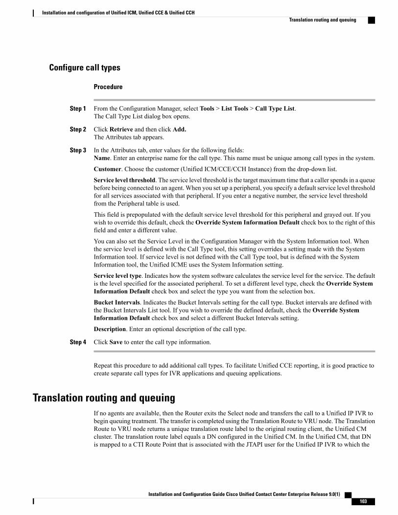
Configure call types
Procedure
Step 1 From the Configuration Manager, select Tools > List Tools > Call Type List.The Call Type List dialog box opens.
Step 2 Click Retrieve and then click Add.The Attributes tab appears.
Step 3 In the Attributes tab, enter values for the following fields:Name. Enter an enterprise name for the call type. This name must be unique among call types in the system.
Customer. Choose the customer (Unified ICM/CCE/CCH Instance) from the drop-down list.
Service level threshold. The service level threshold is the target maximum time that a caller spends in a queuebefore being connected to an agent.When you set up a peripheral, you specify a default service level thresholdfor all services associated with that peripheral. If you enter a negative number, the service level thresholdfrom the Peripheral table is used.
This field is prepopulated with the default service level threshold for this peripheral and grayed out. If youwish to override this default, check theOverride System Information Default check box to the right of thisfield and enter a different value.
You can also set the Service Level in the Configuration Manager with the System Information tool. Whenthe service level is defined with the Call Type tool, this setting overrides a setting made with the SystemInformation tool. If service level is not defined with the Call Type tool, but is defined with the SystemInformation tool, the Unified ICME uses the System Information setting.
Service level type. Indicates how the system software calculates the service level for the service. The defaultis the level specified for the associated peripheral. To set a different level type, check the Override SystemInformation Default check box and select the type you want from the selection box.
Bucket Intervals. Indicates the Bucket Intervals setting for the call type. Bucket intervals are defined withthe Bucket Intervals List tool. If you wish to override the defined default, check the Override SystemInformation Default check box and select a different Bucket Intervals setting.
Description. Enter an optional description of the call type.
Step 4 Click Save to enter the call type information.
Repeat this procedure to add additional call types. To facilitate Unified CCE reporting, it is good practice tocreate separate call types for IVR applications and queuing applications.
Translation routing and queuingIf no agents are available, then the Router exits the Select node and transfers the call to a Unified IP IVR tobegin queuing treatment. The transfer is completed using the Translation Route to VRU node. The TranslationRoute to VRU node returns a unique translation route label to the original routing client, the Unified CMcluster. The translation route label equals a DN configured in the Unified CM. In the Unified CM, that DNis mapped to a CTI Route Point that is associated with the JTAPI user for the Unified IP IVR to which the
Installation and Configuration Guide Cisco Unified Contact Center Enterprise Release 9.0(1) 103
Installation and configuration of Unified ICM, Unified CCE & Unified CCHTranslation routing and queuing
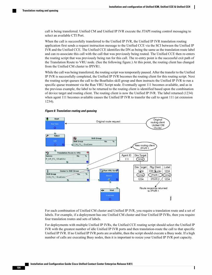
call is being transferred. Unified CM and Unified IP IVR execute the JTAPI routing control messaging toselect an available CTI Port.
When the call is successfully transferred to the Unified IP IVR, the Unified IP IVR translation routingapplication first sends a request instruction message to the Unified CCE via the SCI between the Unified IPIVR and the Unified CCE. The Unified CCE identifies the DN as being the same as the translation route labeland can re-associate this call with the call that was previously being routed. The Unified CCE then re-entersthe routing script that was previously being run for this call. The re-entry point is the successful exit path ofthe Translation Route to VRU node. (See the following figure.) At this point, the routing client has changedfrom the Unified CM cluster to IPIVR1.
While the call was being transferred, the routing script was temporarily paused. After the transfer to the UnifiedIP IVR is successfully completed, the Unified IP IVR becomes the routing client for this routing script. Nextthe routing script queues the call to the BoatSales skill group and then instructs the Unified IP IVR to run aspecific queue treatment via the Run VRU Script node. Eventually agent 111 becomes available, and as inthe previous example, the label to be returned to the routing client is identified based upon the combinationof device target and routing client. The routing client is now the Unified IP IVR. The label returned (1234)when agent 111 becomes available causes the Unified IP IVR to transfer the call to agent 111 (at extension1234).
Figure 6: Translation routing and queuing
For each combination of Unified CM cluster and Unified IP IVR, you require a translation route and a set oflabels. For example, if a deployment has one Unified CM cluster and four Unified IP IVRs, then you requirefour translation routes and sets of labels.
For deployments with multiple Unified IP IVRs, the Unified CCE routing script should select the Unified IPIVR with the greatest number of idle Unified IP IVR ports and then translation-route the call to that specificUnified IP IVR. If no Unified IP IVR ports are available, then the script should execute a Busy node. If a highnumber of calls are executing Busy nodes, then it is important to resize your Unified IP IVR port capacity.
Installation and Configuration Guide Cisco Unified Contact Center Enterprise Release 9.0(1)104
Installation and configuration of Unified ICM, Unified CCE & Unified CCHTranslation routing and queuing

Configure translation routesUse the Translation Route wizard to configure the translation routes for the Unified CM and VRU peripherals.This wizard automates the correct associations with peripheral targets, labels, and routes.
Run the Translation Route Wizard only if you included the Unified CVP in your Unified CCE System.Note
Procedure
Step 1 In the Configuration Manager, select Tools >Wizards > Translation Route Wizard.The Translation Route Wizard introductory dialog box opens.
Step 2 Click Next.The Acquire Lock and Select Configuration Task dialog box opens.
Step 3 Select Create New.Step 4 Click Next.
The Define Translation Route dialog box opens. The graphic on the left of the dialog box shows the entitiesyou are defining while using the Translation Route Wizard.
Step 5 Enter a long and short name for the translation route and, optionally, a description (the short name is used informing target names).
Step 6 Click Next.The Select Configuration dialog box opens.
Step 7 Choose the single peripheral, single routing client configuration from the drop-down list.The graphic changes to show the configuration you select.
Step 8 Click Next.The Select Peripheral Gateway, Peripherals, and Services dialog box opens.
Step 9 Enter values for the following fields:Peripheral Gateway. Choose the gateway target for the translation route.
Peripheral. Choose the single peripheral or the peripheral to route calls to.
Service/Service Array. If the translation route is associated with a single peripheral, choose the serviceassociated with the translation route. If the translation route is associated with multiple VRUs, then select aservice array.
Step 10 Click Next.The Select Routing Clients and Dialed Numbers dialog box opens. Use this dialog box to specify the UnifiedCM peripheral (or VRU peripheral) as the routing client from which translation routed calls originate. Forthe Unified CCE the dialed number string is not applicable.
Step 11 Click Next.The Select Network Trunk Groups for Routing Clients dialog box opens. Choose at least one network trunkgroup to be used in peripheral targets associated with the translation route.
Step 12 Choose a routing client, select a network trunk group value for it, and click Add.
Installation and Configuration Guide Cisco Unified Contact Center Enterprise Release 9.0(1) 105
Installation and configuration of Unified ICM, Unified CCE & Unified CCHConfigure translation routes
The Network Trunk Group appears in the list at the bottom of the dialog box.
Step 13 Click Next.The Configure DAIS dialog box opens.
Step 14 Use this dialog box to specify the DAIS values that map to route points on the VRU. Do one of the following(either a or b:a) To enter a specific DAIS value, click Add DAIS and enter the value.b) To add a range of DAIS values, typically required by a translation route, click Add DAIS Range.
A dialog box prompts you to enter a starting and ending DAIS value. The Translation Route Wizardautomatically generates the DAIS values in the range.
Step 15 Click Next.The Configure Label dialog box appears.
Step 16 16. Use this dialog box to define a label that maps to the DAIS/CTI route points. A label consists of a prefixand a suffix. Each DAIS value requires a unique label. Do one of the following:a) Enter prefixes and suffixes individually.b) Use the buttons in this dialog box to set a range of values or to base the prefix or suffix values on the DAIS
values.
Step 17 Click Next.The Wizard Complete dialog box opens.
Step 18 Click Create Translation Route to create the translation route and its associated entities.First, the Translation Route Wizard displays a success message and then the dialog box appears.
Step 19 Do one of the following:a) To see details about the translation route you just created, click Run Report.b) To return to the beginning of the Translation Route Wizard and perform a new task, select Start New
Task and click Finish.c) To exit the Translation Route Wizard, click Finish.
You can also use the Translation Route Explorer to create a translation route or to modify a translationroute that you created with the Translation Route Wizard. Select Configuration Manager > Tools >Explorer Tools > Translation Route Explorer.
Note
Network VRU scriptsVRU Scripts differ from Unified ICM/CCE/CCH routing scripts. A configured VRU Script runs only whenthe Unified ICM/CCE/CCH instructs it to do so from a routing script. A VRU Script on the UnifiedICM/CCE/CCH is the configured record for the VRU script that resides on the Unified IP IVR. A VRU Scriptexecutes to collect digits, play hold music, or perform many other common IVR functions.
After you configure a Network VRU Script, you can access the VRU in Unified ICM/CCE/CCH scripts,troubleshoot scripts, and perform VRU error checking.
Installation and Configuration Guide Cisco Unified Contact Center Enterprise Release 9.0(1)106
Installation and configuration of Unified ICM, Unified CCE & Unified CCHNetwork VRU scripts

This section describes how to configure individual Network VRU Scripts. You can also create these recordsin bulk using the Bulk Configuration Tool.
Configure Network VRU script
Procedure
Step 1 From the Configuration Manager, select Tools > List Tools > Network VRU Script List.The Network VRU Script List dialog box opens.
Step 2 Click Retrieve and then click Add.Step 3 On the Attributes tab, enter the configuration information for the VRU script as follows:
Network VRU. Specify the Network VRU with which this script should be associated.
VRU Script Name. Enter script name; for example, BasicQ.
Name. Enter the script file name; for example, BasicQ.aef
Timeout [seconds]. Enter 180.
Configuration param. Leave blank.
Customer. Choose the same Unified ICM/CCE/CCH customer you chose for call type from the drop-downlist.
Step 4 Check the Interruptible check box.Step 5 Click Save and the click Close.
What to Do Next
Before you can use a VRU script, you must upload it to the Repository in Unified IP IVR.
Related Topics
Configure VRU script, on page 48
Access to VRUs in Unified ICM/CCE/CCH scriptsAfter you configure the Network VRU and IVR scripts, you can use the Script Editor to write a routing scriptto send a call to the VRU and invoke a specific VRU script.
For deployments that include the Unified CVP, you use the Translation Route to VRU node to send calls tothe Network VRU and invoke IVR scripts. You should not use Translation Route to VRU node for deploymentsthat use the UCCE System PG. Instead, use any one of Queue to Skill Group or Send to VRU nodes.
About Troubleshooting ScriptsIf a timeout occurs on a VRU script, it is possible that the Router does not notify the VRU PIM that a timeouthas occurred. Because the VRU PIM is not informed of the problem, it does not notify the VRU to cancel thescript.
At this point, the options for script flow include the following:
Installation and Configuration Guide Cisco Unified Contact Center Enterprise Release 9.0(1) 107
Installation and configuration of Unified ICM, Unified CCE & Unified CCHNetwork VRU scripts

• The failure path in the Router script sends the call to a label, the VRU PIM gets a Connect and, if theIVR supports it, generates a Cancel message. This is the most common result.
• Before the Router picks a label, the VRU script completes and the VRU sends a Script Result messageto the Router. The Router then sends a Dialogue Failure Event because it is not expecting a Script Result.This is the next most common result.
• The failure path in the Router script tries to run another VRU script. This is not a common result.
Currently, the best resolution to this problem is to use longer time-outs or create shorter VRU scripts. Beaware that the failure exit from the Run VRU Script node is a problem that you may need to resolve.
About VRU error checkingA special call variable VruStatus, allows you to check the result of the last IVR node (Send ToVRU/TranslationRoute to VRU/Run VRU Script) that the Unified ICM/CCE/CCH processed. The following table lists thisvariable's values.
DescriptionMeaningValue
The last VRU node was successful.VRU_SUCCESS0
The last VRU node failed because of a routing orconfiguration error.
VRU_ERROR1
The last Send ToVRU or Translation Route to VRU nodefailed because the routing client did not respond within20 seconds or the last Run VRU Script node failedbecause the timeout limit defined for the script expired.
VRU_TIMEOUT2
The last VRU node did not complete because the callerhung up or was otherwise lost. (Because this causes therouting script to terminate immediately, this value is neverseen.)
VRU_ABORTED3
The last VRU node failed because communication withthe VRU ended unexpectedly.
VRU_DIALOG_FAILED4
The VRU failed because the referenced VRU script wasnot found in the Unified ICM/CCE/CCH configuration.
VRU_SCRIPT_NOT_FOUND5
Routing and administrative script configurationAfter you complete your Unified ICM/CCE/CCH configuration, you canwrite routing scripts and administrativescripts:
• A routing script processes call routing requests from a routing client. Typically it examines severaltargets and applies selection rules to find an available qualified agent or a target with the shortest expecteddelay. You can set up different routing scripts to execute for different types of tasks. You can definecall types in terms of the telephone number the caller dialed, the number the caller is calling from, and
Installation and Configuration Guide Cisco Unified Contact Center Enterprise Release 9.0(1)108
Installation and configuration of Unified ICM, Unified CCE & Unified CCHRouting and administrative script configuration

additional digits entered by the caller. For each call type, you can schedule different routing scripts toexecute on different days or at different times of the day.
• An administrative script runs periodically to perform a task, such as setting variables.
You create, maintain, and monitor Unified ICM/CCE/CCH scripts using the Script Editor.
See:For Information about:
Configuration Guide for Cisco ICM/Unified Contact CenterEnterprise & Hosted
Creating Unified ICM/CCE/CCH scripts
Scripting and Media Routing Guide for Cisco UnifiedICM/Contact Center Enterprise & Hosted
Designing scripts for Unified CCE using theScript Editor
ReportingGuide for CiscoUnified Contact Center Enterprise& Hosted
Planning scripts for your Unified CCEreporting needs
Outbound Option Guide for Cisco Unified Contact CenterEnterprise & Hosted
Creating scripts for Outbound Option
Installation and Configuration Guide Cisco Unified Contact Center Enterprise Release 9.0(1) 109
Installation and configuration of Unified ICM, Unified CCE & Unified CCHRouting and administrative script configuration

Installation and Configuration Guide Cisco Unified Contact Center Enterprise Release 9.0(1)110
Installation and configuration of Unified ICM, Unified CCE & Unified CCHRouting and administrative script configuration

C H A P T E R 7Installation and configuration of Outbound Option
This chapter provides minimal information about installing and configuring the Outbound Option for UnifiedCCE. For more information, see the Outbound Option Guide for Cisco Unified Contact Center Enterprise& Hosted.
• Outbound Option, page 111
• Outbound Option installation prerequisites, page 111
• Outbound Option installation and configuration, page 112
• Outbound dialing campaigns, page 112
Outbound OptionOutbound Option is an optional feature of Unified CCE that provides outbound dialing functionality alongwith the existing inbound capabilities of Unified CCE. With Outbound Option, you can configure contactcenters for automated outbound activities. Agents who are not busy handling inbound requests can performoutbound calls, thereby maintaining a high level of agent productivity.
For Unified CCE, you require a Cisco voice gateway to place customer calls.
Outbound Option installation prerequisitesBefore you install the Outbound Option software, you must have a working Cisco Unified Contact CenterEnterprise system with a Router, Logger, Administration & Data Server, an UCCE System PG or UnifiedCM and VRU PGs, CTI Server, and Unified CM connectivity with agents and CTI Route Points. During theinstallation of Unified ICM/Unified CCE/Unified CCHwhen you are setting the Logger component propertiesusing the Web Setup Tool, be sure to enable Outbound Option.
Related Topics
Component software configuration tasks, on page 25
Installation and Configuration Guide Cisco Unified Contact Center Enterprise Release 9.0(1) 111

Outbound Option installation and configurationFor more information about installing and configuring the Outbound Option, see the “Installing OutboundOption” chapter in Outbound Option Guide for Cisco Unified Contact Center Enterprise & Hosted .
Make sure that you complete the prerequisites listed in Chapter 3 of this guide. For more information aboutthe tasks you must complete and the prerequisites you must satisfy, see the “Before You Begin” section in theOutbound Option Guide for Cisco Unified Contact Center Enterprise & Hosted.
In the Installing Outbound Option chapter in the Outbound Option Guide for Cisco Unified Contact CenterEnterprise & Hosted follow the instructions in these sections:
• IPCC Enterprise Outbound Configuration
• Cisco Unified Communications Manager/Gateway Configuration
• Software Installation and Database Creation
Outbound dialing campaignsAfter you install Outbound Option, you can begin creating outbound dialing campaigns. Instructions forcreating andmanaging outbound campaigns, and for writing scripts for use with OutboundOption, are providedin the Outbound Option Guide for Cisco Unified Contact Center Enterprise & Hosted.
Installation and Configuration Guide Cisco Unified Contact Center Enterprise Release 9.0(1)112
Installation and configuration of Outbound OptionOutbound Option installation and configuration

C H A P T E R 8Cisco Unified Customer Voice Portal and CiscoUnified Contact Center Enterprise
This chapter provides information about Cisco Unified Customer Voice Portal (Unified CVP) and how youmust deploy in a Unified CCE system. It also describes some guidelines and best practices to follow whileyou use the Unified CVP in a Unified CCE environment.
For more information about installing Unified CVP in a Unified CCE deployment, see the Installation andUpgrade Guide for Cisco Unified Customer Voice Portal.
For more information about planning and configuring the Unified CVP for Unified CCE, see theConfigurationand Administration Guide for Cisco Customer Voice Portal and the Planning Guide for Cisco UnifiedCustomer Voice Portal.
Follow the instructions in this chapter if you are using the Unified CVP (as opposed to the Unified IP IVR) for queuing in your Unified CCE system. (If you are deploying the Unified IP IVR instead of the UnifiedCVP, see Chapter 5, “Installing and Configuring Unified IP IVR for Unified CCE.”)
• Unified CVP, page 113
• Preconfiguration steps—Unified CVP for Unified CCE, page 115
Unified CVPYou can deploy the Unified CVP in the Unified CCE system to provide call control, IVR queuing, and calltreatment.
The Unified CVP integrates with the Unified CCE via a VRU Peripheral Gateway (PG). This integrationallows the Unified CCE to control Unified CVPVoIP switching and IVR services. This integration also allowsthe Unified CCE to control the agent selection application and to initiate the Real-Time Transport Protocol(RTP) stream transfer from the VoiceXML gateway to the selected agent.
The Unified CVP integration with the Unified CCE requires that you use the traditional Unified CM PG forUnified CCE integration with the Unified CM.
The Unified CVP can also provide IVR services for Unified CCE Outbound Option IVR campaigns andpost-call customer surveys.
This guide provides basic information for configuring the Unified CVP for the Unified CCE. The exact mannerin which you configure the Unified CVP depends on the deployment model of the Unified CVP that you are
Installation and Configuration Guide Cisco Unified Contact Center Enterprise Release 9.0(1) 113

using for your system. For more information about configuring Unified CVP in your deployment model, seeAdministration and Configuration Guide for Cisco Unified Customer Voice Portal (Unified CVP) and thePlanning Guide for Cisco Unified Customer Voice Portal.
Unified CVP installation prerequisitesBefore installing and configuring Unified CVP, you must do the following:
NotesUnified CVP InstallationPrerequisite
On the Unified CM, you must configure the Unified CVP Voice Browseras a Gateway or SIP Trunk for the Call Server. If you use the H323 protocol,you need an H323 Gatekeeper configured and an H323 Gatekeepercontrolled trunk.
Install the Unified CM.
In the Unified ICME/Unified CCE/Unified CCH, you must complete thefollowing:
• Configured a Network VRU (type 10)
• Configured a VRU PG and a Unified CM PG (and installed the PGs)
• Installed the JTAPI client on the PG
• Configured Network VRU Trunk Groups
• Configured skill groups, persons, agents, and routes
• Configured ECC Variables
• Configured call types, Dialed Numbers, Device Targets, Labels, anda Dialed Number Plan.
• Configured Translation Routes (optional depending on the call flow)
• Configured scripts--VRU, routing, and administrative
See Chapter 6 for instructions.
Install the UnifiedICME/Unified CCE/UnifiedCCH and the PG containing theVRU PIMs.
Unified CVP as Type 10 Network VRUMost implementations of the Unified CVP are covered by a type 10 Network VRU, which is designed tosimplify the configuration requirements in Unified CVP Comprehensive Model deployments.
The type 10 Network VRU has the following behavior:
• There is a handoff of routing client responsibilities to the Unified CVP switch leg.
• There is an automatic transfer to the Unified CVP VRU leg, resulting in a second transfer in the case ofcalls originated by the VRU, ACD, or Unified CM.
Installation and Configuration Guide Cisco Unified Contact Center Enterprise Release 9.0(1)114
Cisco Unified Customer Voice Portal and Cisco Unified Contact Center EnterpriseUnified CVP installation prerequisites

• For calls originated by the Unified CM, the Correlation ID transfer mechanism is used. The CorrelationID is automatically added to the end of the transfer label defined in the Type 10 Network VRUconfiguration.
• The final transfer to the Unified CVP VRU leg is similar to a type 7 transfer, in that a release messageis sent to the VRU prior to any transfer.
In Unified CVP implementations, define a single type 10NetworkVRU and associate all Unified ICME/UnifiedCCE/Unified CCH VRU scripts with it. It requires one label for the Unified CVP Switch leg routing client,which transfers the call to the Unified CVPVRU leg. If calls are to be transferred to Unified CVP fromUnifiedCM, you need another label for the Unified CM routing client, and this label must be different from the labelyou used for the CVP Routing Client. This label transfers the call to the Unified CVP Switch leg. The UnifiedICME/Unified CCE/Unified CCHRouter sends this label to the Unified CMwith a Correlation ID concatenatedto it. Configure the Unified CM to handle these arbitrary extra digits.
Configure the Unified CVP Switch leg peripheral to point to the same type 10 Network VRU. Also, associateall incoming dialed numbers for calls that are to be transferred to the Unified CVP with a Customer Instancethat points to the same type 10 Network VRU.
For calls that originate at a Call Routing Interface VRU or at a TDM ACD, use a TranslationRouteToVRUnode to transfer the call to the Unified CVP Switch leg peripheral. For all other calls, use either a SendToVRUnode, a node that contains automatic SendToVRU behavior (such as the queuing nodes), or a RunExternalScript.
For more information, see the Cisco Unified Customer Voice Portal Solution Reference Network Design(SRND).
Preconfiguration steps—Unified CVP for Unified CCEAfter installation, you must configure the Unified CVP for integration with the Unified CCE. The followinglist provides the planning information you need before configuring:
• The Unified CVP call flow model you are implementing.
• The network topology for your system, including addresses and names of the solution components.
• The failover strategy for Gateways, Unified CVP components, and media servers.
• The strategy for inbound call routing (that is, dial-peers versus Gatekeeper or Proxy Server).
• The naming resolution system for Gateways (DNS versus configured on the Gateway).
• If using a VRU other than Unified CVP, the VRU trunk group number and number of trunks.
• The locale values to be used for ASR and/or TTS.
•Whether the same set of VRUs are to be used for all cases, or whether that is determined separately foreach customer (dialed number).
Generally, in addition to the pre-requisites of installing and configuring the Unified CM and the UnifiedICME/Unified CCE/Unified CCH, configuring the Unified CVP means configuring the following:
• Unified CVP Call Server (SIP or H.323)
• IOS Gateway
• Gatekeeper (H323) or a SIP Proxy
Installation and Configuration Guide Cisco Unified Contact Center Enterprise Release 9.0(1) 115
Cisco Unified Customer Voice Portal and Cisco Unified Contact Center EnterprisePreconfiguration steps—Unified CVP for Unified CCE

For more information about planning and configuring the Unified CVP for the Unified CCE, see theConfiguration and Administration Guide for Cisco Customer Voice Portal and Planning Guide for CiscoUnified Customer Voice Portal..
Related Topics
Unified CCE with Unified CVP plan, on page 20
Installation and Configuration Guide Cisco Unified Contact Center Enterprise Release 9.0(1)116
Cisco Unified Customer Voice Portal and Cisco Unified Contact Center EnterprisePreconfiguration steps—Unified CVP for Unified CCE
C H A P T E R 9Installation of CTI OS Server Agent andSupervisor Desktop Software for Cisco UnifiedContact Center Enterprise
You can deploy either Cisco CTI OS or Cisco Agent Desktop/Cisco Supervisor Desktop in the Unified CCEsystem to provide Agent and Supervisor Desktops. This chapter provides information on installing theseoptions for Unified CCE.
• Agent and Supervisor Desktops for Unified CCE, page 117
• Agent and Supervisor Desktop installation prerequisites, page 118
• Agent and Supervisor Desktop installation tasks, page 118
• CTI OS Server and desktop installations, page 119
• Cisco Agent Desktop installation and configuration, page 120
Agent and Supervisor Desktops for Unified CCECisco Computer Telephony Integration Object Server (CTI OS) and Cisco Agent Desktop are server-basedCTI solutions that provide desktops used by contact center agents and supervisors. Both desktop packagesare supported by the Unified CCE. You deploy one or the other in your Unified CCE system:
• CTI OS includes the CTI OS Server, CTI OS Agent Desktop, Unified CCE Supervisor Desktop, CTIOS Toolkit, and the Client Interface Library (CIL). It provides an object-oriented software developmenttoolkit for development and deployment of CTI applications.
• Cisco Agent Desktops and Cisco Supervisor Desktops includes the Desktop Administrator, AgentDesktop, and Supervisor Desktop.
Regardless of which agent desktop software you deploy; that is, Cisco Agent Desktop or CTI OS, bothcommunicate to the Unified CCE via the CTI server, which you set up using the Peripheral Gateway SetupTool. The CTI Server is the CTI gateway into the Unified CCE data and services. It allows the Unified CCEto deliver agent, call, and customer data in real time to a server and/or workstation application as events occurthroughout the life of a call.
Installation and Configuration Guide Cisco Unified Contact Center Enterprise Release 9.0(1) 117
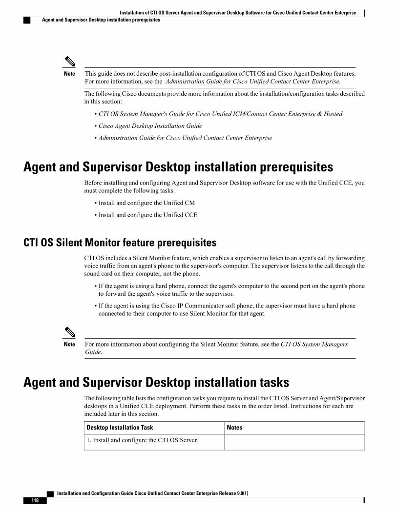
This guide does not describe post-installation configuration of CTI OS and Cisco Agent Desktop features.For more information, see the Administration Guide for Cisco Unified Contact Center Enterprise.
Note
The following Cisco documents provide more information about the installation/configuration tasks describedin this section:
• CTI OS System Manager's Guide for Cisco Unified ICM/Contact Center Enterprise & Hosted
• Cisco Agent Desktop Installation Guide
• Administration Guide for Cisco Unified Contact Center Enterprise
Agent and Supervisor Desktop installation prerequisitesBefore installing and configuring Agent and Supervisor Desktop software for use with the Unified CCE, youmust complete the following tasks:
• Install and configure the Unified CM
• Install and configure the Unified CCE
CTI OS Silent Monitor feature prerequisitesCTI OS includes a Silent Monitor feature, which enables a supervisor to listen to an agent's call by forwardingvoice traffic from an agent's phone to the supervisor's computer. The supervisor listens to the call through thesound card on their computer, not the phone.
• If the agent is using a hard phone, connect the agent's computer to the second port on the agent's phoneto forward the agent's voice traffic to the supervisor.
• If the agent is using the Cisco IP Communicator soft phone, the supervisor must have a hard phoneconnected to their computer to use Silent Monitor for that agent.
For more information about configuring the Silent Monitor feature, see the CTI OS System ManagersGuide.
Note
Agent and Supervisor Desktop installation tasksThe following table lists the configuration tasks you require to install the CTI OS Server and Agent/Supervisordesktops in a Unified CCE deployment. Perform these tasks in the order listed. Instructions for each areincluded later in this section.
NotesDesktop Installation Task
1. Install and configure the CTI OS Server.
Installation and Configuration Guide Cisco Unified Contact Center Enterprise Release 9.0(1)118
Installation of CTI OS Server Agent and Supervisor Desktop Software for Cisco Unified Contact Center EnterpriseAgent and Supervisor Desktop installation prerequisites

NotesDesktop Installation Task
2. Install CTI OS Agent and Supervisor Desktops,OR install Cisco Agent Desktop and Cisco SupervisorDesktops.
3. Start CTI OS Services.
CTI OS Server and desktop installationsCTI OS incorporates the CTI OS Server, the CTI OS Toolkit, Cisco Agent Desktop, Cisco Supervisor Desktopand Client Interface Library.
Note • The CTI OS Server is installed on the same server as the PG or CG.
• Do not install the desktop software on the PG, CG or CTI OS Server.
CTI OS Server installationFor more information about installing CTI OS Server, see the chapter “CTI OS Server Installation” in the CTIOS System Manager's Guide for Cisco Unified ICM/Contact Center Enterprise & Hosted.
CTI OS Supervisor Desktop installation
CTI OS uses certificates (self-signed or third-party) for authentication between the CTI OS Server anddesktop clients. This is an optional feature and the warning is applicable only if you enable security whenyou install the CTI OS Server. Before you install the Supervisor Desktop, youmust knowwhich (self-signedor third party) certificate type your company uses. After you install the Supervisor Desktop, you need tocopy key and request files from the client to the Certificate Authority (CA) machine, sign them, and thenreturn signed files to the client. If you are not already familiar with the CTI OS certificate signing proceduresused at your company, please consult your CTI OS administrator or the CTI OS System Manager's Guidefor Cisco Unified ICM/Contact Center Enterprise & Hosted before proceeding with desktop softwareinstallation.
Warning
For more information about installing the CTI OS Supervisor Desktop see the chapter “CTI Toolkit DesktopClient Installation” in the CTI OS System Manager's Guide for Cisco Unified ICM/Contact Center Enterprise& Hosted.
Installation and Configuration Guide Cisco Unified Contact Center Enterprise Release 9.0(1) 119
Installation of CTI OS Server Agent and Supervisor Desktop Software for Cisco Unified Contact Center EnterpriseCTI OS Server and desktop installations
CTI OS Agent Desktop installation
CTI OS uses certificates (self-signed or third party) for authentication between the CTI OS Server anddesktop clients. This is an optional feature and the warning is applicable only if you enable security whenyou install the CTI OS Server. Before you install the Supervisor Desktop, youmust knowwhich (self-signedor third party) certificate type your company uses. After you install the Supervisor Desktop, you mustcopy key and request files from the client to the Certificate Authority (CA) machine, sign them, and thenreturn signed files to the client. If you are not already familiar with the CTI OS certificate signing proceduresused at your company, please consult your CTI OS administrator or the CTI OS System Manager's Guidefor Cisco Unified ICM/Contact Center Enterprise & Hosted before proceeding with desktop softwareinstallation.
Warning
For more information about installing the CTI OSAgent Desktop, see the chapter “CTI Toolkit Desktop ClientInstallation” in the CTI OS System Manager's Guide for Cisco Unified ICM/Contact Center Enterprise &Hosted
Cisco Agent Desktop installation and configuration
Cisco Agent Desktop pre-installation requirementsFor the Cisco Agent Desktop applications to work properly, you must organize your agents into teams andyou must designate some as supervisors. Create agents, teams, and supervisors in the Unified CCE beforeyou install Cisco Agent Desktop software.
The Cisco Agent Desktop is an out-of-the-box desktop application that enables the agent to perform agentstate control (including login, logout, ready, not ready, and wrap up) and call control (including answer,release, hold, retrieve, transfer, conference, make call). The Cisco Agent Desktop requires use of a CiscoUnified IP phone or Cisco IP Communicator (softphone). You can use other phones as well using the Mobile
Installation and Configuration Guide Cisco Unified Contact Center Enterprise Release 9.0(1)120
Installation of CTI OS Server Agent and Supervisor Desktop Software for Cisco Unified Contact Center EnterpriseCTI OS Agent Desktop installation

Agent option. Other features, such as an integrated chatting application, call recording, and workflowautomation, may be included. See the following figure.
Figure 7: Cisco Agent Desktop
Use the following worksheet to assemble the configuration information you require during Unified AMinstallation. Depending on your configuration, you may not need to complete every section of the worksheet.
ValueItem
Primary Directory Services
Host name / IP address
Logical contact center name
Secondary Directory Services
Host name / IP address
Base Services
Host name / IP address
Recording & Playback Services
Host name / IP address
Host name / IP address
VoIP Monitor Services
Host name / IP address
Installation and Configuration Guide Cisco Unified Contact Center Enterprise Release 9.0(1) 121
Installation of CTI OS Server Agent and Supervisor Desktop Software for Cisco Unified Contact Center EnterpriseCisco Agent Desktop pre-installation requirements

ValueItem
Host name / IP address
Host name / IP address
Host name / IP address
Unified CM (Publisher)
Host name / IP address
Unified CM (Subscribers)
Host name / IP address
Host name / IP address
Host name / IP address
Host name / IP address
Unified CM Database
Unified CM version
Database login ID
Database password
ipccUnified CCE SQL Logger Database
(On Central Controller)
Instance name
Login ID
Password
Side A Host name / IP address
Side B Host name / IP address
1000CTI Service Associated with Unified CM
Peripheral ID
Side A Host name / IP address
Port
Side B Host name / IP address
Installation and Configuration Guide Cisco Unified Contact Center Enterprise Release 9.0(1)122
Installation of CTI OS Server Agent and Supervisor Desktop Software for Cisco Unified Contact Center EnterpriseCisco Agent Desktop pre-installation requirements

ValueItem
Port
CTI Service Associated with Unified IP IVR
Peripheral ID
Side A Host name / IP address
Port
Side B Host name / IP address
Port
CTI OS (Server 1)
(On PG)
Peripheral ID
Side A Host name / IP address
Port
Side B Host name / IP address
Port
CTI OS (Server 2)
(On PG)
Peripheral ID
Side A Host name / IP address
Port
Side B Host name / IP address
Port
Backup Data
Location path
Cisco Agent Desktop component installation orderTo install the Cisco Agent Desktop, follow the step-by-step installation instructions included in the CiscoAgent Desktop Installation Guide.
Installation and Configuration Guide Cisco Unified Contact Center Enterprise Release 9.0(1) 123
Installation of CTI OS Server Agent and Supervisor Desktop Software for Cisco Unified Contact Center EnterpriseCisco Agent Desktop component installation order
You must install the Unified AM components in the following order:
1 Services
2 Desktop Administrator
3 Supervisor Desktop and Agent Desktops
You install the Cisco Agent Desktop Services and the Desktop Administrator from the Cisco Agent DesktopCD. The Cisco Agent Desktop Configuration application runs automatically after you install the services andDesktop Administrator on the Unified CCX server. Following that, you can change your configuration settingsby launching the Desktop Administrator.
The supervisor and the Agent Desktops are installed from the Web server on which you install the UnifiedAM services.
For more information, see the Cisco Desktop Administrator User's Guide.
Start CTI OS Service after installationThe CTI OS Server runs as a Windows service on the host computer. You can start, stop, or cycle the CTIOS Server from the Service Management Page in the Web Setup Tool, which you can run in any supportedbrowser. Optionally, you can use the Unified CCE Service Control tool on the desktop.
To start the CTI OS Service form the Unified CCE Service Control tool, complete the following steps:
Procedure
Step 1 On the CTI OS Server machine, open Unified CCE Service Control.Step 2 Select CTI OS Service.Step 3 Click Start.
Installation and Configuration Guide Cisco Unified Contact Center Enterprise Release 9.0(1)124
Installation of CTI OS Server Agent and Supervisor Desktop Software for Cisco Unified Contact Center EnterpriseStart CTI OS Service after installation

C H A P T E R 10Script Editor Localization
You can localize Script Editor by installing the Language Pack.
• Supported languages, page 125
• Language Pack installation, page 125
Supported languagesEnglish is the default language and is installed with Unified CCE Setup installer. If you want to localize ScriptEditor, you must run the Language Pack.
The following 5 languages are supported by Script Editor:
• English (US)
• French (France)
• French (Canada)
• Japanese
• Chinese (Simplified)
The Language Pack Installer is on the same DVD with the Unified CCE Setup media.
Language Pack installationIn Unified ICM 9.0(1), the Language Pack installation is a separate process from the Unified ICM setup. Runthe Language Pack Installer to select the language you want after you complete the Unified CCE setup.
If you install the Unified ICM on a English Windows Server 2008 R2, you can run Language Pack to localizeScript Editor.
If you install the Unified ICM on a localized version of Windows Server 2008 R2, you should be all set afterrunning the Language Pack.
Installation and Configuration Guide Cisco Unified Contact Center Enterprise Release 9.0(1) 125
If you plan to install the Unified CCE on a multilingual version of Windows Server 2008 R2, you must followthe procedure listed in Installing the Multilingual User Interface (MUI) OS Language Pack on an EnglishWindows Server 2008 R2, on page 126 to set up your Windows system.
If you install the Unified ICM on a multilingual version of Windows Server 2008 R2, you must make surethat the language you selected during the Language Pack installation matches the language setting inWindowsregional options.
To check that there is a match, do the following:
1 Select Start > Control Panel > Clock, Language and Region.
2 In the Clock, Language and Region window, click Region and Language.
3 Click the Administrative tab.
4 On theAdministrative tab, inLanguage for non-Unicode programs section, the language underCurrentLanguage for non-Unicode programs should be the same as the language you selected during theLanguage Pack installation.
Check language settingIf you install the Unified CCE on a multilingual version of Windows 2008, you must make sure that thelanguage you select during the Language Pack installation matches the language setting in Windows regionaloptions.
Procedure
Step 1 Select Start > Settings > Control Panel > Regional and Language Options.Step 2 Click the Advanced tab.Step 3 Under Select a language to match the language version of the non-Unicode programs you want to use,
the language displayed on the pull-down list should be the same as the language you selected during theLanguage Pack installation.
What to Do Next
Follow the procedure listed in “Date format adjustment after localization” to change the date format used bythe Jaguar Server.
Related Topics
Date format adjustment after localization
Installing the Multilingual User Interface (MUI) OS Language Pack on anEnglish Windows Server 2008 R2
To localize the Windows system, perform the following steps:
Installation and Configuration Guide Cisco Unified Contact Center Enterprise Release 9.0(1)126
Script Editor LocalizationCheck language setting

Procedure
Step 1 Set up an English Windows Server 2008 R2 with SP 1.Step 2 Insert the MUI installation DVD from Microsoft. The languages supported are included in the installation
DVD.Step 3 Select Start > Settings > Control Panel > Clock, Language and Region.Step 4 In the Clock, Language and Region window, click Region and Language.Step 5 In the Region and Language dialog box, click Keyboards and Languages tab.Step 6 On the Keyboards and Languages tab, click Install/Uninstall Languages.Step 7 In the Install/Uninstall Languages dialog box, click Install display languages.Step 8 Click Browse folder, locate the folder of the language you wish to install from MUI DVD.Step 9 Select the language that you want to install and than click Next.Step 10 Review the Microsoft Software License Terms and select Accept and click Next.Step 11 When the installation completes, reboot your machine.
The Windows system is now in the localized language.
Installation and Configuration Guide Cisco Unified Contact Center Enterprise Release 9.0(1) 127
Script Editor LocalizationInstalling the Multilingual User Interface (MUI) OS Language Pack on an English Windows Server 2008 R2

Installation and Configuration Guide Cisco Unified Contact Center Enterprise Release 9.0(1)128
Script Editor LocalizationInstalling the Multilingual User Interface (MUI) OS Language Pack on an English Windows Server 2008 R2

A P P E N D I X ACisco Unified Contact Center EnterpriseLaboratory System Setup
This appendix provides advice on how to set up Unified CCE in a laboratory environment.
• Unified CCE laboratory hardware requirements, page 129
• Sprawler installation, page 130
Unified CCE laboratory hardware requirementsUsing Unified CCE in a laboratory environment requires less equipment than you need in a productionenvironment. A laboratory that includes Outbound Option and multichannel components can be deployed onas few as three boxes for a laboratory setup. In a more heavily trafficked production environment, you caninstall the Unified IP IVR and the Unified ICM/CCE/CCHLogger on separate machines. You can also separatethe CTI OS Agent and Supervisor Desktops.
You require the following minimum hardware in a Unified CCE laboratory. For more information about boxspecifications and OS requirements, see the Hardware and System Software Specification (Bill of Materials)for Cisco Unified ICM/Contact Center Enterprise & Hosted.
SpecificationsHardware
Model 7960 (three or more)Cisco IP phones
1 CiscoMedia Convergence Server (MCS)or equivalent for VOS.
Unified CM + Unified IP IVR
1CiscoMedia Convergence Server (MCS)or equivalent
Unified CCE. Router, Logger, Administration & Data Server,UCCESystemPG, CTI Server, CTIOS Server, OutboundOptionDialer and Media Routing PG for Outbound Option (optional)
You cannot have a CCE system with Outbound Optionin a CVP environment. This requires three PG types onthe same machine, which is a deployment that Ciscodoes not support.
Note
Installation and Configuration Guide Cisco Unified Contact Center Enterprise Release 9.0(1) 129

SpecificationsHardware
1CiscoMedia Convergence Server (MCS)or equivalent
CTI OS Agent and Supervisor Desktops or Cisco SupervisorDesktop Agent/Supervisor Desktop server
Sprawler installationFor a laboratory setup, you can choose to install all of the Unified ICM/CCE/CCH components on one server,called a sprawler. Before you configure the Unified ICM/CCE/CCH software in the laboratory, ensure thattheMicrosoftWindows planning and pre-installation tasks are complete. For more information, see the StagingGuide for Cisco Unified ICM/Contact Center Enterprise & Hosted.
Installation of Unified ICM/CCE/CCH components on sprawlerIn a production environment, you typically install Unified ICM/CCE/CCH components on several differentmachines. In a laboratory environment, however, you can install all Unified ICM/CCE/CCH components ona single machine, called a sprawler.
You can install the following Unified ICM/CCE/CCH components on a sprawler:
• Administration & Data Server
• Logger
• Router
• Peripheral Gateways (PGs)
• CTI Server
• CTI OS Server
• CTI OS Agent and Supervisor Desktop
• Outbound Option Dialer
A sprawler installation requires some specific installation settings for each Unified ICM/CCE/CCH component.These are listed in the following table.
Installation and Configuration Guide Cisco Unified Contact Center Enterprise Release 9.0(1)130
Cisco Unified Contact Center Enterprise Laboratory System SetupSprawler installation

Do the following:When installing the:
Specify the following in the Web Setup Add Administration & DataServer wizard:
1 On the Role page, select one of the following roles:
• For a small to medium deployment, select AdministrationServer, Real-time and Historical Data Server and DetailData Server (AW-HDS-DDS)
• For a large deployment, select Administration Server andReal-time and Historical Data Server (AW-HDS)
2 On the Database and Options page, check ConfigurationManagement Service (CMS) Node
When using the ICM Database Administrator tool to create a HistoricalData Server database, set the data size to 500 MB and the log size to 100MB.
Administration & Data Server
Specify the following in the Web Setup Add Router wizard:
1 On the Deployment page, specify Side A and Simplexed.
2 On the Router Connectivity page, enter the host name or IP Addressof the Side A Router in the Side B fields.
Router
Specify the following in the Web Setup Add Logger wizard:
1 On the Deployment page, specify Side A and Simplexed.
2 On the Central Controller Connectivity page, enter the host name orIP Address of the Side A Router in the Side B Router field, and enterthe host name or IP Address of the Side A Logger in the Side B Loggerfield.
When you use the ICMDatabase Administrator tool to create a HistoricalData Server database, set the data size to 500 MB and the log size to 100MB.
When you use the ICM Database Administrator tool to create theOutbound Option private database, set the data size to 300 MB and thelog size to 100 MB.
Logger
1 On the Device Management Protocol Properties dialog box, selectRouter is local (for Side A and Side B).
2 On the Peripheral Gateway Network Interfaces dialog box, removeany value references for Side B.
Call Manager PG, VRU PG orUCCE System PG, and MR PG
Installation and Configuration Guide Cisco Unified Contact Center Enterprise Release 9.0(1) 131
Cisco Unified Contact Center Enterprise Laboratory System SetupInstallation of Unified ICM/CCE/CCH components on sprawler

Do the following:When installing the:
1 On the CTI Server Properties dialog box, choose Production modeand Side A. In the CG node properties section of that box, select aCGNode from the ID field drop-down list. Be sure that the CG numbermatches the PG number; for example, for PG1, the ID field shouldread CG1.
2 On the CTI Server Component Properties dialog box, make a note ofthe Client Connection Port Number, which is typically 42027.
3 On the CTI Network Interface Properties dialog box, be sure that thereare values for Node A but none for Node B in the three sections ofthat box.
CTI Server
1 On the first Outbound Option Dialer Properties dialog box, chooseProduction Mode.
2 On the second Outbound Option Dialer Properties dialog box, leavethe CTI Server B and CTI Server Port B field blank.
Outbound Option Dialer
On the CTI Server Information dialog box, leave the Name or IP Addressand Port fields in the System B section blank.
CTI OS Server
On the CTIOS Server Information dialog box, leave the Name or IPAddress and Port fields in the CTIOS Server B section blank.
CTI OS Client Toolkit (includesCTI OS Agent and SupervisorDesktops)
Installation and Configuration Guide Cisco Unified Contact Center Enterprise Release 9.0(1)132
Cisco Unified Contact Center Enterprise Laboratory System SetupInstallation of Unified ICM/CCE/CCH components on sprawler

I N D E X
A
Active Directory 14requirements 14
Administration and Data Server 57in Unified ICM/CCE/CCH 57
Administration Client 57in Unified ICM/CCE/CCH 57
agent 91, 92, 93assigning to a skill group 93assigning to a supervisor 92configuring 91configuring agent teams 93
agent desk settings 63, 65configuring 65in Unified ICM/CCE/CCH 63Ring No Answer feature 63
all-in-one system 130see sprawler 130
B
Barge-in 94Bulk Configuration Tool 29, 62
for Unified CM 29Unified ICM/CCE/CCH 62
C
call flow 5with Unified IP IVR 5
Call Search Space 35controlling 35
call type 102, 103configuring 103defined 102
checklists 21, 22, 25, 28, 39, 60, 118configuration of Unified ICM/CCE/CCH 60for desktops 118hardware installation 21
checklists (continued)software configuration tasks 25software installation 22Unified CM configuration 28Unified IP IVR configuratoin 39
Cisco Agent Desktop (CAD) 120installing 120
Cisco Unified Communications Manager 27see Unified CM 27
core components 2for Unified CCE 2software 2
CTI OS 118, 124Silent Monitor feature 118starting services 124
CTI Route Points 31in Unified CM 31
CTI Server 57, 117in Unified ICM/CCE/CCH 57
D
desktops 117, 118agent and supervisor 117CAD 117CTI OS 117installation prerequisites 118installing 117
device target 99, 100configuring 100defined 99
dial plan 19, 20examples 19Unified CCE with Unified CVP 20Unified CCE with Unified IP IVR 19
dialed number 95, 96configuring 96defined 95
Installation and Configuration Guide Cisco Unified Contact Center Enterprise Release 9.0(1) IN-1
E
Emergency Assist 94
F
fault tolerance 35setting a recovery number 35
G
Generic PG 67
H
hardware requirements 13Historical Data Server (HDS) 57
in Unified ICM/CCE/CCH 57
I
installation 1, 21, 22, 28, 38, 59, 112, 113, 117, 125, 130caution 1checklist for Unified CCE software 22desktops 117hardware checklist 21Language Pack 125Outbound Option 112Unified CM 28Unified CVP 113Unified ICM/CCE/CCH 59Unified ICM/CCE/CCH on a sprawler 130Unified IP IVR 38
Intercept 94internationalization 16IPTA skill group attribute 88
J
JTAPI client 55, 80installing on PGs 80resynchronizing with Unified CCX 55
L
label 101, 102configuring 102
label (continued)defined 101
laboratory system 129for Unified CCE 129
Language Pack 126installing 126
languages 125, 126installing the Language Pack 125localizing the user interface 126
licensing 15localization 16, 125, 126
checking the language setting 126Script Editor UIs 125setting up the MUI Pack 126supported languages 125
Logger 57in Unified ICM/CCE/CCH 57
M
Media Routing Domains 67configuring for media classes 67
Media Routing PG 80see MR PG 80
MR PG 81, 82configuring 81configuring peripherals 81setting up 82
multichannel components 13
N
Network VRU 66, 106, 107, 114configuring a script 107script 106setting up in Unified ICM/CCE/CCH 66type 10 for Unified CVP 114
Network VRU Bank 85configuring 85
O
operating system 14requirements 14
optional components 4Outbound Option 4
Outbound Option 59, 111, 112defined 111dialing campaigns 112enabling on Unified ICM/CCE/CCH 59
Installation and Configuration Guide Cisco Unified Contact Center Enterprise Release 9.0(1)IN-2
Index

Outbound Option (continued)installation prerequisites 111
P
parent/child 1peripheral 67, 69
defined 67for UCCE System PG 69
peripheral gateway 67see PG 67
person record 90configuring 90
PG 67, 68, 74, 77, 80Generic PG 67MR PG 80types 67UCCE System PG 68Unified CM PG 67, 77VRU PG 67, 74
platform specifications 13post routing 52
configuring for Unified IP IVR 52
R
requirements 13, 14, 15, 120Active Directory 14licensing 15operating system 14pre-installation for CAD 120server hardware 13third-party software 14
Ring No Answer feature 63with Unified CVP 63
route 97configuring 97defined 97
Router 57in Unified ICM/CCE/CCH 57
routing 49, 108post routing 49scripts 108translation routing 49
S
Script Editor 125localization 125
scripts 107, 108accessing 107administrative 108Network VRU 107routing 108troubleshooting 107
server 13requirements 13
service members 89configuring 89
services 86configuring 86
Silent Monitor feature 118skill group 87, 88
configuring 88default 87defined 87IPTA attribute 88
software 2, 4, 14core components 2optional components 4third-party 14
sprawler 130defined 130installing com 130
T
third-party software 14requirements 14
translation routing 50, 105configuring for Unified IP IVR 50configuring in Unified ICM/CCE/CCH 105
trunk groups 83, 84configuring 84defined 83
type 10 Network VRU 114for Unified CVP 114
U
UCCE System PG 68, 71configuring 68defined 68setting up 71
Unified CCE 129laboratory system 129
Unified CCMP 4, 14defined 4third-party requirements 14
Installation and Configuration Guide Cisco Unified Contact Center Enterprise Release 9.0(1) IN-3
Index
Unified CCX 38, 40accessing Administration utility 40platform for Unified IP IVR 38
Unified CM 27, 28, 29, 30, 31, 32, 34, 35accessing Administration utility 29Bulk Configuration tool 29configuration task list 28configuring Agent IP Phones 30configuring CTI Ports 31configuring CTI Route Points 31configuring for Unified CVP 34configuring IP phones 29configuring users 32controlling the call search space 35defined 27Extension Mobility feature 30installing 28setting a recovery number 35
Unified CM PG 77, 78configuring 77setting up 78
Unified CVP 20, 113, 114, 115before you configure 115dial plan example 20installation prerequisites 114installing and configuring 113type 10 Network VRU 114
Unified ICM/CCE/CCH 57, 58, 59, 60, 61, 62, 63, 66, 84, 85, 86, 87, 89, 90, 91, 94, 95, 97, 99, 101, 102, 106, 130
Administration and Data Server 57Administration Client 57agent 91agent desk settings 63Bulk Configuration Tool 62call type 102components 57Configuration Manager defined 61configuring 60CTI Server 57defined 57device target 99dialed number 95enabling Outbound Option 59Historical Data Server (HDS) 57installation prerequisites 58installing 59installing on a sprawler 130label 101Logger 57
Unified ICM/CCE/CCH (continued)Network VRU 66Network VRU Bank 85Network VRU script 106person records 90Router 57routes 97service members 89services 86skill groups 87supervisory features 94trunk groups 84
Unified IP IVR 19, 38, 39, 40, 41, 46, 48, 52, 55, 56accessing Unified CCX Administration utility 40configuration task list 39configuring a Unified CM telephony provider 40configuring call control groups 41configuring ICM Subsystem 46configuring on Unified CCE 56configuring post routing 52configuring VRU scripts 48defined 38dial plan example 19installation prerequisites 39installing 38on Unified CCX platform 38resynchronizing telephony data 55rresynchonizing JTAPI client 55starting the Unified CCX engine 55
unsupported features 16
V
version interoperability 15VRU 107, 108
accessing in scripts 107error checking 108
VRU PG 74, 75configuring 74setting up 75
W
windows 14requirements 14
Installation and Configuration Guide Cisco Unified Contact Center Enterprise Release 9.0(1)IN-4
Index