installation and homeowners guidefiles.kohler.com.cn/pdfs/1516246642238_k-77404t-0.pdfinstallation...
TRANSCRIPT

Installation and Homeowners Guide
Underscore Bathroom Heater S300
S300
K-77404T-0
KOHLER CHINA INVESTMENT CO., LTD NO.158, JIANG CHANG SAN ROAD,JING'AN DISTRICT, SHANGHAI, PRC POST CODE: 200436
( ) 158 200436
1322966-T01-B
-1-
BEFORE YOU BEGIN
�
�
�
�
Please read these instructions carefully to familiarize
yourself with the required tools, materials, and installation
sequences. Follow the sections that pertain to your
particular installation. This will help you avoid costly
mistakes. In addition to proper installation, read all
operation and safety instructions.
All information in these instructions is based upon the
latest product information available at the time of
publication. Kohler China reserves the right to make
changes in product characteristics, packaging, or
availability at any time without notice.
These instructions contain important care, cleaning, and
warranty information -
.
This product complies with GB 4706.1-2005, GB4706.23-
2007 and GB 4706.27-2008.
please leave instructions for the
consumer
�
�
�
�
,
-
GB 4706.1-2005 GB4706.23-2007 GB
4706.27-2008
WARNING: Risk of electrical shock.
WARNING: Risk of electrical shock.
WARNING: Risk of electrical shock.
A licensed
electrician should make all electrical connections.
Connect only to
a circuit protected by a typical two-pole circuit breaker.
Disconnect
power before servicing.
�
�
�
�
�
�
�
�
�
�
Tape measureLevelScrew driverConnection wireWire cutterInsulation tapeBushingPercussion DrillPen KnifeWrench
�
�
�
�
�
�
�
�
�
�
RECOMMENDED TOOLS AND MATERIALSRECOMMENDED TOOLS AND MATERIALS
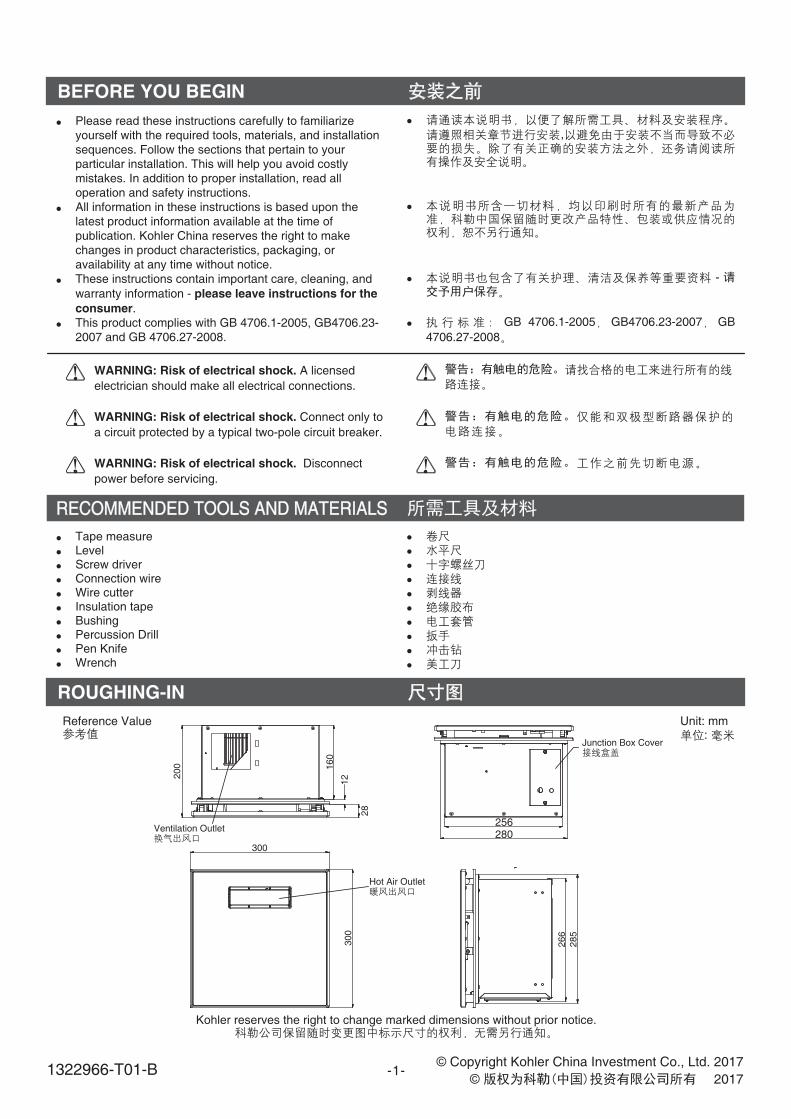
Kohler reserves the right to change marked dimensions without prior notice.
Unit: mm:
Reference Value
ROUGHING-IN
300
300
266
285
Junction Box Cover
280256
200 160
12
28
Ventilation Outlet
Hot Air Outlet
©
©
Copyright Kohler China Investment Co., Ltd. 2017
20171322966-T01-B

-2-
SPECIFICATIONS
Model
Voltage/Frequency /220V~/50Hz
K-77404T-0 K-77404T-0
220V~/50Hz
Rated Input Power 2150W 2150W
Heater Power
Fan Power
Ventilation Power
2125W 2125W
25W 25W
25W 25W
Ventilation Volume
Ventilation Noise
Ingress Protection
2.2m /min3
2.2m /min3
43dB 43dB
IPX2 (Bathroom Heater) IPX2 ( )
IPX4 (Remote Control) IPX4 ( )
SIMPLIFIED DIAGRAM OF THE UNIT
Note: Plaster or other ceiling opening dimension: 275 X 275 (mm)
275 X 275 (mm)
+50
+50
+50
+50
Keel
Clamp
Air Exhaust Pipe
BTP4*8 TriangularSelf Tapping ScrewBTP4*8
BTP4*8 TriangularSelf Tapping ScrewBTP4*8
Ventilation Outlet Assy.
Air Outlet Window
L-mounting BracketL
Keel Lock
1322966-T01-B
-3-
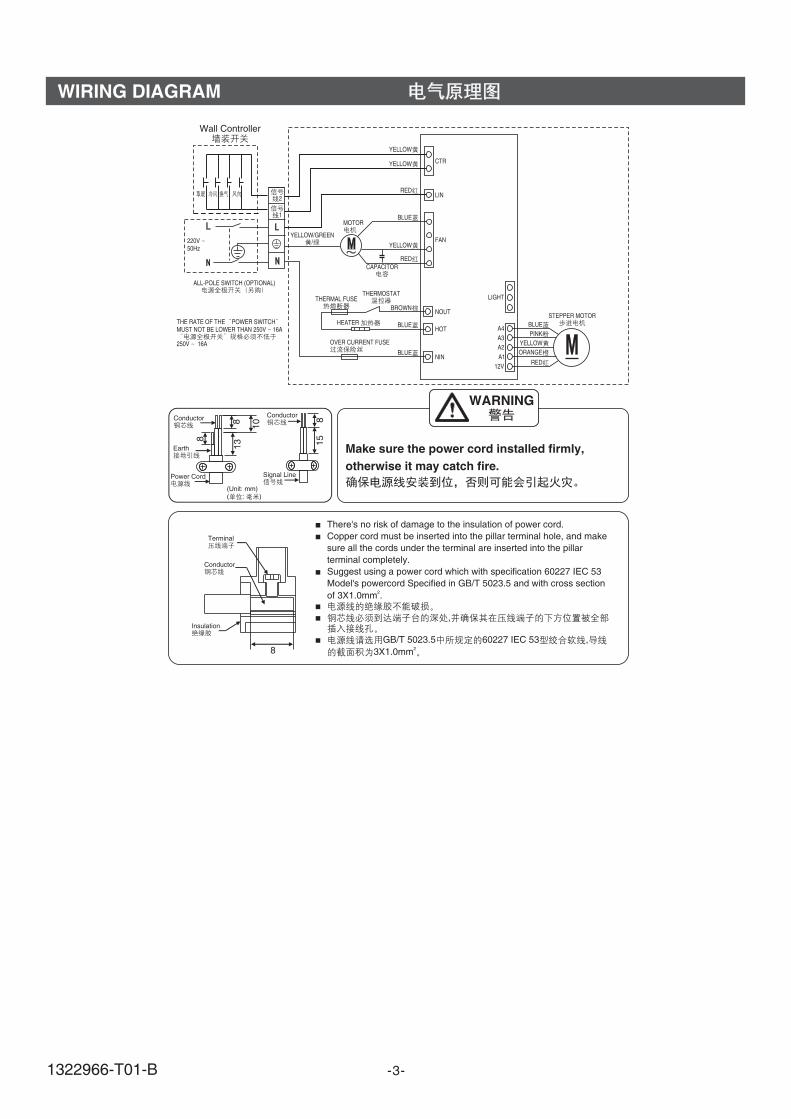
WIRING DIAGRAM
CTR
LIN
FAN
NOUT
HOT
NIN
LIGHT
A4A3A2A1
12V
STEPPER MOTORBLUE
RED
PINKYELLOWORANGE
HEATER
THERMOSTATTHERMAL FUSE
OVER CURRENT FUSE
MOTOR
CAPACITOR
ALL-POLE SWITCH (OPTIONAL)
220V50Hz
THE RATE OF THE POWER SWITCHMUST NOT BE LOWER THAN 250V 16A
250V 16A
RED
RED
BLUE
BLUE
BLUE
BROWN
YELLOW
YELLOW
YELLOW
YELLOW/GREEN/
2
1
�
�
�
�
�
�
There's no risk of damage to the insulation of power cord.
Copper cord must be inserted into the pillar terminal hole, and make
sure all the cords under the terminal are inserted into the pillar
terminal completely.
Suggest using a power cord which with specification 60227 IEC 53
Model's powercord Specified in GB/T 5023.5 and with cross section
of 3X1.0mm .
,
GB/T 5023.5 60227 IEC 53 ,
3X1.0mm
2
2
Terminal
Conductor
Insulation
8
(Unit: mm)( : )
WARNING
Make sure the power cord installed firmly,
otherwise it may catch fire.
ConductorConductor
Earth
Power Cord
8
8 8
13 15
10
Wall Controller
Signal Line
1322966-T01-B

-4-
PREPARATIONS BEFORE INSTALLATION
A. Preparation before the installation A.
1. Open the hole of outlet windowMake sure that the outlet window s position (it should belower than the outlet of the bathroom heater to prevent thewater come back to the bathroom heater from the outletwindow), and open a round hole on the wall.
2. Outlet window installationFix the air exhaust pipe to the outlet window on the wallwith the clamp as the preparation of bathroom heaterinstallation. Seal the pipe and the outlet window withfoaming agent.
1.
(
)
2.
Ceiling
Air Exhaust Pipe
Wall
Inside Outside
Outlet Window
The situation of outlet window on thewall outside.
The situation of outlet window on thewall inside.
Outlet Window
Outlet Window
Hole on the Wall Hole on the Wall
80mm80mm
115mm115mm
B. Take out the bathroom from package. B.
Bathromm Heater
1322966-T01-B
-5-
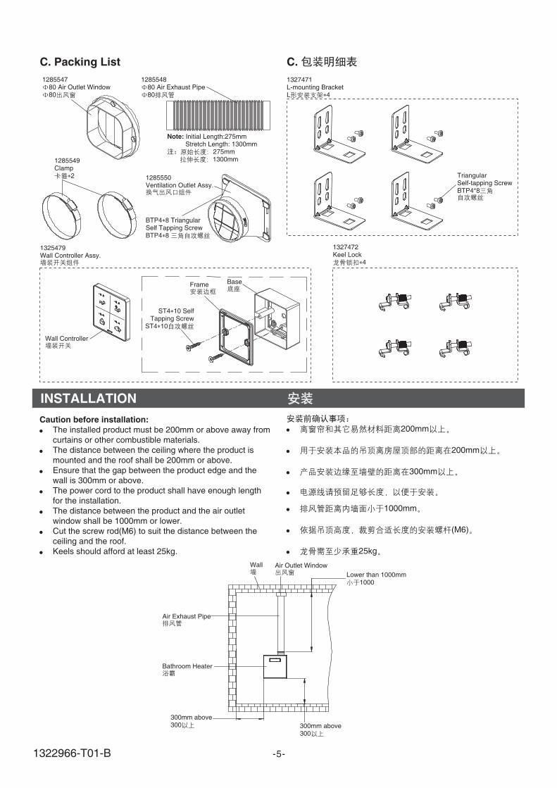
C. Packing List C.
128554780 Air Outlet Window80
128554880 Air Exhaust Pipe80
1285549Clamp
2 1285550Ventilation Outlet Assy.
Note: Initial Length:275mmStretch Length: 1300mm
275mm1300mm
BTP4 8 TriangularSelf Tapping ScrewBTP4 8
TriangularSelf-tapping ScrewBTP4*8
INSTALLATION
Caution before installation:
�
�
�
�
�
�
�
The installed product must be 200mm or above away from
curtains or other combustible materials.
The distance between the ceiling where the product is
mounted and the roof shall be 200mm or above.
Ensure that the gap between the product edge and the
wall is 300mm or above.
The power cord to the product shall have enough length
for the installation.
The distance between the product and the air outlet
window shall be 1000mm or lower.
Cut the screw rod(M6) to suit the distance between the
ceiling and the roof.
Keels should afford at least 25kg.
�
�
�
�
�
�
�
200mm
200mm
300mm
1000mm
(M6)
25kg
Air Exhaust Pipe
Wall
Lower than 1000mm1000
300mm above300 300mm above
300
Air Outlet Window
Bathroom Heater
1327472Keel Lock
4
1327471L-mounting BracketL 4
ST4 10 SelfTapping Screw
ST4 10
Base
Wall Controller
1325479Wall Controller Assy.
Frame
1322966-T01-B
-6-
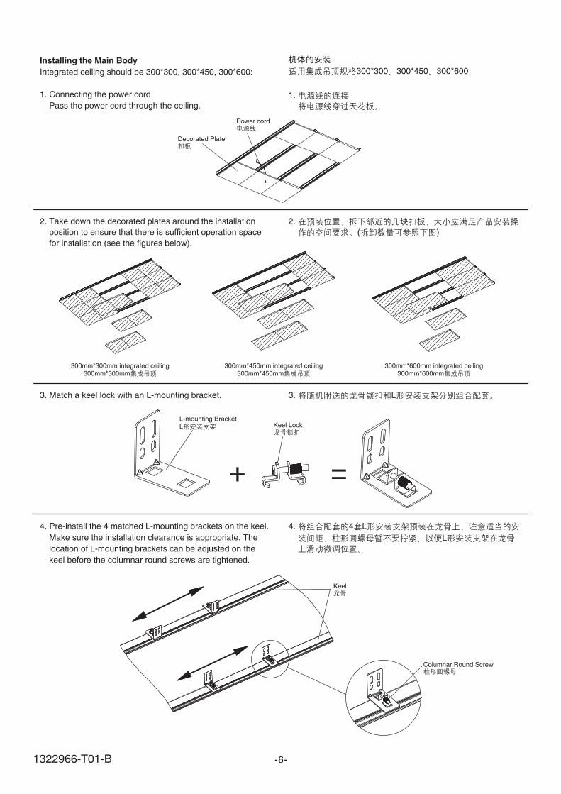
Installing the Main Body
Integrated ceiling should be 300*300, 300*450, 300*600:
1. Connecting the power cord
Pass the power cord through the ceiling.
300*300 300*450 300*600
1.
Power cord
Decorated Plate
2. Take down the decorated plates around the installation
position to ensure that there is sufficient operation space
for installation (see the figures below).
3. Match a keel lock with an L-mounting bracket.
4. Pre-install the 4 matched L-mounting brackets on the keel.
Make sure the installation clearance is appropriate. The
location of L-mounting brackets can be adjusted on the
keel before the columnar round screws are tightened.
2.
( )
3. L
4. 4 L
L
300mm*300mm integrated ceiling300mm*300mm
300mm*450mm integrated ceiling300mm*450mm
300mm*600mm integrated ceiling300mm*600mm
L-mounting BracketL Keel Lock
Keel
Columnar Round Screw
1322966-T01-B
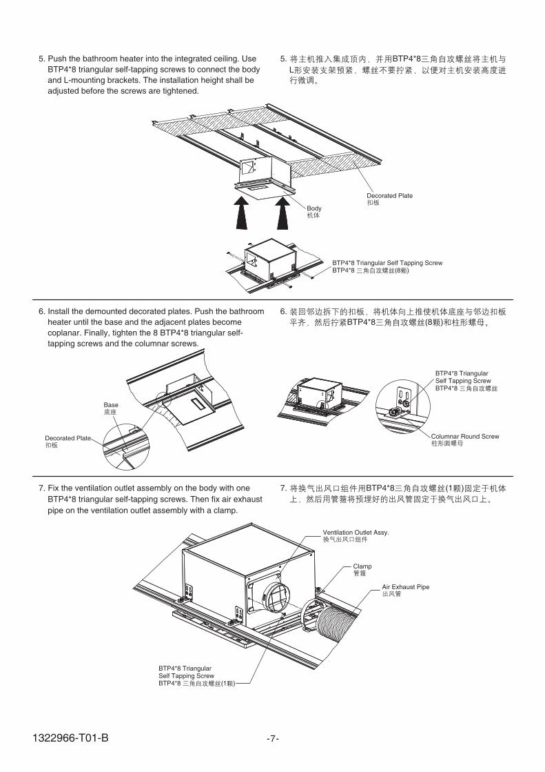
5. Push the bathroom heater into the integrated ceiling. Use
BTP4*8 triangular self-tapping screws to connect the body
and L-mounting brackets. The installation height shall be
adjusted before the screws are tightened.
6. Install the demounted decorated plates. Push the bathroom
heater until the base and the adjacent plates become
coplanar. Finally, tighten the 8 BTP4*8 triangular self-
tapping screws and the columnar screws.
5. BTP4*8
L
6.
BTP4*8 (8 )
7. Fix the ventilation outlet assembly on the body with one
BTP4*8 triangular self-tapping screws. Then fix air exhaust
pipe on the ventilation outlet assembly with a clamp.
7. BTP4*8 (1 )
-7-
BTP4*8 Triangular Self Tapping ScrewBTP4*8 (8 )
BTP4*8 TriangularSelf Tapping ScrewBTP4*8
Decorated Plate
Decorated Plate
Body
Base
BTP4*8 TriangularSelf Tapping ScrewBTP4*8 (1 )
Ventilation Outlet Assy.
Air Exhaust Pipe
Clamp
Columnar Round Screw
1322966-T01-B

-8-
8. Take down the wiring cover plate. Insert the power cord
and 2 signal lines into the wire terminals. Tighten the
terminal screws and fix the lines. Finally, mount the wiring
cover plate.
9. Put back and install the remaining plates. (Installation
finished)
8.
3 2
9. ( )
Power cord
L N
Wiring Terminal
WALL CONTROLLER INSTALLATION
Fix the wall controller frame and the base with two screws.
Then connect two signal lines with the wall controller and
tighten with signal line screws. Finally, fix the wall controller
on the frame.
2
Wall Controller
Signal Line
Wall ControllerSignal Line
Frame
Screw*2
Base
Self-tapping ScrewST4*10
Wire Box Cover
1322966-T01-B
-9-
USER'S GUIDE
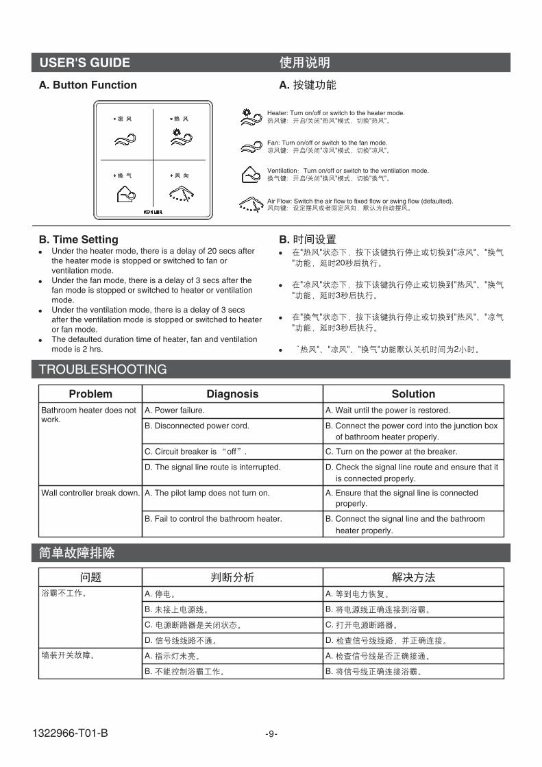
A. Button Function A.
B. Time SettingUnder the heater mode, there is a delay of 20 secs afterthe heater mode is stopped or switched to fan orventilation mode.Under the fan mode, there is a delay of 3 secs after thefan mode is stopped or switched to heater or ventilationmode.Under the ventilation mode, there is a delay of 3 secsafter the ventilation mode is stopped or switched to heateror fan mode.The defaulted duration time of heater, fan and ventilationmode is 2 hrs.
�
�
�
�
B." " " " "
" 20
" " " " "
" 3
" " " " "
" 3
" " " " " 2
�
�
�
�
TROUBLESHOOTING
Problem Diagnosis Solution
Bathroom heater does notwork.
Wall controller break down.
A. Power failure.
D. The signal line route is interrupted.
B. Disconnected power cord.
A. The pilot lamp does not turn on.
C. Circuit breaker is off .
B. Fail to control the bathroom heater.
A. Wait until the power is restored.
D. Check the signal line route and ensure that it
is connected properly.
B. Connect the power cord into the junction box
of bathroom heater properly.
A. Ensure that the signal line is connected
properly.
C. Turn on the power at the breaker.
B. Connect the signal line and the bathroom
heater properly.
A.
D.
B.
A.
C.
B.
A.
D.
B.
A.
C.
B.
Heater: Turn on/off or switch to the heater mode./ " " " "
Fan: Turn on/off or switch to the fan mode./ " " " "
Ventilation Turn on/off or switch to the ventilation mode./ " " " "
Air Flow: Switch the air flow to fixed flow or swing flow (defaulted).
1322966-T01-B
CARE & CLEAN
1.
2.
3.
4.
5.
6.
7.
8.
9.
-10-
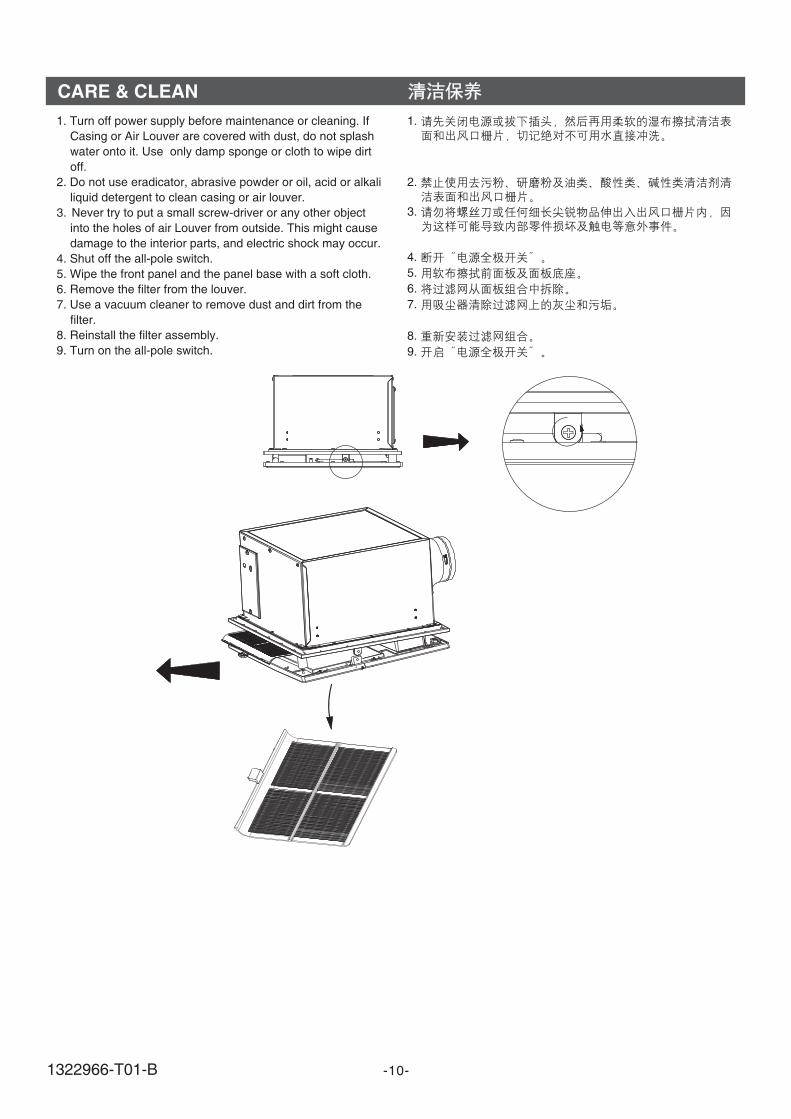
1. Turn off power supply before maintenance or cleaning. If
Casing or Air Louver are covered with dust, do not splash
water onto it. Use only damp sponge or cloth to wipe dirt
off.
2. Do not use eradicator, abrasive powder or oil, acid or alkali
liquid detergent to clean casing or air louver.
3. Never try to put a small screw-driver or any other object
into the holes of air Louver from outside. This might cause
damage to the interior parts, and electric shock may occur.
4. Shut off the all-pole switch.
5. Wipe the front panel and the panel base with a soft cloth.
6. Remove the filter from the louver.
7. Use a vacuum cleaner to remove dust and dirt from the
filter.
8. Reinstall the filter assembly.
9. Turn on the all-pole switch.
1322966-T01-B

IMPORTANTCONSUMER INFORMATION
1. When AC power unit is connected to 220V AC powersupply, corresponding protective measures should betaken.
2. Please confirm no water penetration at the connection areaof AC wire, and the connection area is not easy to beaffected by damp.
3. The head AC power supply must be protected withappropriate fuse.
4. Please confirm the AC power supply should be shut offbefore maintaining the products with AC power related.
5. All electrical connection must be compliance with relatedregulation and codes.
6. All installation staff should be well familiar with installationinstruction.
Notice: Troubleshooting needs to be done by
professional of KOHLER CHINA. Users are not suggested
to do this without help. Please remember that the
checking and repairs done by users themselves could
easily cause damage to the machine or cause physical
harm to the person.
1. 220V
2.
3.
4.
5.
6.
-11-1322966-T01-B