installation and maintenance instructions for gc52 ... pressure/pdfs/gc52 instruction...
TRANSCRIPT

Installation and MaintenanceInstructions for GC52Differential PressureTransmitter
LOOK FOR THISAGENCY MARK ONOUR PRODUCTS
© 2007 Ashcroft Inc. 250 East Main Street, Stratford, CT 06614 USATel: 203-378-8281, Fax: 203-385-0402, www.ashcroft.com All sales subject to standard terms and conditions of sale.I&M011-10160 -7/10/08
Version 5.0 10/07
I&M011-10160-GC52 7/17/08 4:11 PM Page 1

2
I&M011-10160-GC52 7/17/08 4:11 PM Page 2

3
CONTENTSCAUTION ............................................................................................ 4-5
1. PREFACE .......................................................................................... 5
2. OVERVIEW ........................................................................................ 5
3. FEATURES ........................................................................................ 5
4. SPECIFICATIONS.............................................................................. 6
5. MOUNTING ........................................................................................ 8
5.1 Mounting Location ........................................................................ 8
5.2 Mounting Options ........................................................................ 8
5.3 Pressure Connection.................................................................... 8
6. PIPING .............................................................................................. 9
7. WIRING .............................................................................................. 10
7.1 Cable / Wiring Specifications........................................................ 10
7.2 Wiring Instructions........................................................................ 10
8. DISPLAY FUNCTIONS ...................................................................... 13
9. MODE CHANGES.............................................................................. 14
10. POWER-ON MESSAGE .................................................................... 14
11. MEASUREMENT MODE .................................................................. 15
11.1 Filter (Damping) .......................................................................... 15
11.2 Pressure Display Mode (Re-scaling in “inH20” units) .................. 15
11.3 Linear Display Mode (Re-scaling in arbitrary user defined units) .................................. 16
11.4 Min/Max Display .......................................................................... 19
12. ZERO ADJUSTMENT MODE ............................................................ 20
13. SETTING MODE ................................................................................ 20
13.1 Setting Items for Pressure Display Mode (Re-scaling in “inH20” units) ........................................................ 21
13.2 Setting Items for Linear Display Mode (Re-scaling in arbitrary user defined units) .................................. 22
13.3 Setting Procedure ........................................................................ 25
13.4 Loop Check .................................................................................. 25
14. DIMENSIONAL DRAWINGS.............................................................. 26
15. Maintenance ...................................................................................... 27
I&M011-10160-GC52 7/17/08 4:11 PM Page 3

4
GENERAL:A failure resulting in injury or damage may be caused by excessiveoverpressure, excessive vibration or pressure pulsation, excessive in-strument temperature, corrosion of the pressure containing parts, orother misuse. Consult Ashcroft Inc., Stratford, Connecticut, USA beforeinstalling if there are any questions or concerns.
OVERPRESSURE:Pressure spikes in excess of the rated overpressure capability of the trans-mitter may cause irreversible electrical and/or mechanical damage to thepressure measuring and containing elements.
Fluid hammer and surges can destroy any pressure transmitter and must al-ways be avoided. A pressure snubber should be installed to eliminate thedamaging hammer effects. Fluid hammer occurs when a liquid flow is sud-denly stopped, as with quick closing solenoid valves. Surges occur when flowis suddenly begun, as when a pump is turned on at full power or a valve isquickly opened.
Liquid surges are particularly damaging to pressure transmitters if the pipe isoriginally empty.To avoid damaging surges, fluid lines should remain full (ifpossible), pumps should be brought up to power slowly, and valves openedslowly.To avoid damage from both fluid hammer and surges, a surge chambershould be installed.
Symptoms of fluid hammer and surge’s damaging effects:• Pressure transmitter exhibits an output at zero pressure (large zero offset).• Pressure transmitter output remains constant regardless of pressure• In severe cases, there will be no output.
FREEZING:Prohibit freezing of media in pressure port. Unit should be drained to preventpossible overpressure damage from frozen media.
STATIC ELECTRICAL CHARGES:Any electrical device may be susceptible to damage when exposed to staticelectrical charges.To avoid damage to the transmitter observe the following:• Ground the body of the transmitter BEFORE making any electrical
connections.• When disconnecting, remove the ground LAST!Note: The shield and drain wire in the cable (if supplied) is not connected to thetransmitter body, and is not a suitable ground.
WARNING! READ BEFORE INSTALLATION
I&M011-10160-GC52 7/17/08 4:11 PM Page 4

5
USE IN LIFE SUPPORT DEVICESAshcroft Inc. products are not authorized for use as critical components in lifesupport devices or systems without the express written approval of the Gen-eral Manager, Stratford Operations of Ashcroft Inc. As used herein:
Life support devices or systems are devices or systems which, (a) are in-tended for surgical implant into the body, or (b) support or sustain life, andwhose failure to perform, when properly used in accordance with instructionsfor use provided in the labeling, can be reasonably expected to result in asignificant injury to the user.
A critical component is any component of a life support device or systemwhose failure to perform can be reasonably expected to cause the failure ofthe life support device or system, or to affect its safety or effectiveness.
1. PREFACEThank you for purchasing the GC52 Rangeable Differential PressureTransmitter. Refer to the Ashcroft GC52 Data Sheet for product specifica-tions and applicable operating conditions.
2. OVERVIEWThe GC52 is a 4-20mA loop powered (two-wire) differential pressure trans-mitter with integral display incorporating Ashcroft’s proven SiGlas siliconbased variable capacitance sensor with stainless steel media isolation di-aphragms and silicone pressure transmission fluid.The device was designedto offer the user small size and user adjustable ranging for applications suchas tank level measurements and gas / liquid flow measurements.
3. FEATURES(1)Media Compatibility: Wetted materials consist of 316 stainless steel,
alumina ceramic and viton to handle a wide range of media with theability to offer ranges as low as 4˝ W.C. F.S. (URL).
(2)Linear Scaling Function: The linear (scaling) function allows the userto adjust zero and span values providing a corresponding 4-20mA output signal.
(3)Digital Filter Function: User adjustable damping of the output signalby means of internally calculated moving average to provide a stableoutput signal in applications where the user wants to reduce the pulsat-ing of the display and / or output signal.
(4)LED Back Light: To supplement the LCD display when conditions re-quire (dark area, night etc.).
I&M011-10160-GC52 7/17/08 4:11 PM Page 5
6
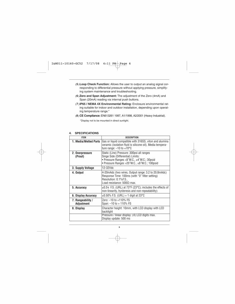
(5)Loop Check Function: Allows the user to output an analog signal cor-responding to differential pressure without applying pressure, simplify-ing system maintenance and troubleshooting.
(6)Zero and Span Adjustment: The adjustment of the Zero (4mA) andSpan (20mA) reading via internal push buttons.
(7)IP65 / NEMA 4X Environmental Rating: Enclosure environmental rat-ing suitable for indoor and outdoor installation, depending upon operat-ing temperature range.*
(8)CE Compliance: EN613261 1997, A1/1998, A2/2001 (Heavy Industrial).
*Display not to be mounted in direct sunlight.
Gas or liquid compatible with 316SS, viton and aluminaceramic (isolation fluid is silicone oil). Media tempera-ture range: –10 to +70°CStatic (Line) Pressure: 300psi all rangesSinge Side (Differential) Limits: • Pressure Ranges <8˝W.C., ±4˝W.C.; 30psid• Pressure Ranges >20˝W.C., ±8˝W.C.; 100psid12-32Vdc4-20mAdc (two wires, Output range: 3.2 to 20.8mAdc)Response Time: 100ms (with “0” filter setting)Resolution: 0.1%F.S., Load resistance: 500Ω max.±0.5% F.S. (URL) at 73°F (23°C); includes the effects ofnon-linearity, hysteresis and non-repeatability)±0.50% F.S. (URL) + 1 digit at 23°CZero: –10 to +110% FSSpan: –10 to + 110% FSCharacter height: 10mm, with LCD display with LEDbacklightPressure / linear display: (4) LCD digits max.Display update: 500 ms
4. SPECIFICATIONS
1. Media/Wetted Parts
2. Overpressure(Proof)
3. Supply Voltage4. Output
5. Accuracy
6. Display Accuracy7. Rangeability /
Adjustment8. Display
ITEM DESCRIPTION
I&M011-10160-GC52 7/17/08 4:11 PM Page 6

7
9. Units
10. Setting Adjustments
11. Enclosure
12. Pressure Connection13. Electrical
Termination
14. Memory Protection15. EMC Directive16. Operating
Temperature17. Storage
Temperature18. Vibration19. Shock20. Insulation
Resistance 21. Weight
Pressure Units: inH2O (2), (1) arbitrary
Internal key switches (Mode, T, S)Scaling function: Linear outputFilter function: User adjustable output damping selectfrom 0, 2, 4, 8 and 16 (None, 2, 4, 8, and 16 (s)).Loop check function: User adjustable output for loop/system check and troubleshooting, 4-20mA.Material: Aluminum die castEnvironmental Rating: IP65 / NEMA 4X1⁄4 NPT female pressure ports w/equalizing valveCable Gland (Optional): Cable diameter 0.35 to 0.47˝(9-12mm)1⁄2 NPT Female Conduit Adapter (Optional) Terminal Block: 14-22 AWG (stranded or solid wire)Permanently stored by EEPROM (nonvolatile memory)CE Compliance: EN61326/1997, A1/1998, A2/2001–10 to 60°C (14 to 140°F)
–20 to 70°C (–4 to 158°F)
5g’s, 150Hz10g’s, 16ms50Vdc, 100MΩ or more
Approx. 670g (1.5lbs)
I&M011-10160-GC52 7/17/08 4:11 PM Page 7

8
5. MOUNTING5.1 General
The GC52 was designed to be mounted using the bracket supplied.Pressure connections via the (2) 1⁄4 NPT female pressure ports. Al-though the display can be rotated in 90 degree increments by remov-ing the display cover it is preferable to orientate the electricaltermination downward, particularly in applications where protectionfrom the environment is required.
5.2 Mounting OrientationIt is preferable to orientate the unit with the pressure ports eitherdownward or upward. If mounting with pressure ports to the side an“orientation effect” will be seen at zero pressure as the pressure gen-erated by the silicone oil fill will appear as a zero offset. If mounting inthis manner this effect may be taken out by re-setting zero in finalmounting orientation.
5.3 Installing Pressure Port Manifold(1) Mounting 25.4mm Manifold (1⁄4˝ NPT female ports)
Manifold is secured using the (4) socket head bolts (M4x40) andappropriate allen wrench which is supplied. Check for dust anddirt on the O-ring and seal area, clean if necessary, before in-stalling to ensure proper connection. The direction of the manifoldis not important, determine best position by ability to operate theequalizing valve.The equalizing valve is used to open both portsto the line pressure at time of installation. Once installed and thesystem has been pressurized the valve needs to be closed to iso-late the low and high pressure sides of the device.
Tighten the equalizing valve with a torque of 0.75 ft-lbs±15%.When loosening the valve do not back off by more than threeturns from the closed position.
(2) Panel MountingSimilar to (1) above except that the GC52 is put between the man-ifold and the bracket and then the (4) socket head bolts (M4x40)are installed.
I&M011-10160-GC52 7/17/08 4:11 PM Page 8

9
(2) 1/4˝ NPTF
1.4 (35)
.55 (14)
.83 (21)
1.8 (45.4)
1.0 (25.4) Hex .83 (21)
.33 (8.5)
Equalizingvalve
• 1.0 in. (25.4mm) mounting manifold
6. PIPINGNote: High (H) and Low (L) pressuresides of the device are marked on theyellow label affixed to the housing ofthe unit.
Install the high pressure side of the ap-plied differential pressure in the pres-sure inlet of the high pressure side (H)and the low pressure side in the pres-sure inlet of the low pressure side (L).
(Refer to the outline drawing of section 14.)
After the piping is completed check for leaks.
(1) Piping of 1.0 in (25.4mm) Manifold (1⁄4˝ NPT female ports)Use caution when installing to keep metal chips and other debris fromentering pressure transmitter. In addition, when sealing tape is used,do not apply to last two threads at the end of the fitting
!
Lower connection diagramConnection: Lower side.
I&M011-10160-GC52 7/17/08 4:11 PM Page 9

10
Terminal Strip
CableRequirements
SMKDSP1.5/2-5.08 Phoenix Contact
• Two core shielded cable• Cable outer diameter: 0.35˝ to 0.47˝ 9-12mm
(Required for correct installation with CableGland option)
• Wire Gauge: 14-22 AWG (multi-strand or solid)
Note:• When transporting and / or mounting do not apply excessive shock
or use device as a step.
• The piping should be of proper length so as not to apply load to theconnection point on the transmitter.
• At the time of mounting or when bleeding air from the device be sureto open the equalizing valve with a flathead screwdriver so that ex-cessive pressure (more than the allowable maximum differential pres-sure) is not applied to the differential pressure sensor. Maximum torqueto apply to equalizer valve is 0.75 ft-lbs ±5%.
7. WIRING7.1 Cable/Wire Specifications
Use appropriate cable described below which is suitable for powersupply requirements and ground to housing.
7.2. Wiring Instructions • To reduce potential for noise do not run pressure transmitter cable /
wires alongside (same conduit as) high voltage (line power) lines.For optimum results use dedicated conduit for GC52 cable / wires.
• If using the Cable Gland termination option must use cable withinpreviously noted diameters to maintain environmental ratings.
• When connecting shield / drain wire, only connect one end whichshould be at the receiver ground.
• Wiring stripping instructions, remove cable jacket 2-3˝ and strip wires±0.25˝. Shield / drain wire should not be exposed at the pressuretransmitter termination.
• Remove cover and carefully remove the display to access the termi-nal strip, take care not to mishandle the display and associated elec-tronics.
I&M011-10160-GC52 7/17/08 4:11 PM Page 10

11
• Turn display over to expose terminal strip, make positive and negative connections, insert wire depth is equal to recommended strip length (0.25˝).
+ -
Terminal box
Display (board)
Shield
Power source
+ - Receiver
Transmission cable
CASE
DISPLAY
CAP
Inside sensor Line
LCD holder
Notch
Transmission cab(Twist)
Sheath
Display
Wire terminals
WireTurn with a screwdriver
LCD clips (4)
Display board
Power supply terminal block
I&M011-10160-GC52 7/17/08 4:11 PM Page 11

12
• After completing connections locate retaining clips in the appropri-ate notches and carefully place into the housing. Be sure that inter-nal sensor transmission wire does not cross the power supply linesjust installed.
• If using the Cable Gland be sure to properly tighten sealing grommetbefore applying any tension on the cable, the cable gland providesstrain relief and environmental sealing.
• Tighten GC52 cover to maintain environmental rating.• Connect to power source and receiver and power on to confirm cor-
rect wiring (see Section 10 for more detail).• Power Supply Requirements: Although the 4-20mA signal can travel
over long distances one of the most common problems is inadequatepower at the pressure transmitter due to the voltage drop across theloop. Be sure to review table below to determine that 12-32V is get-ting to the pressure transmitter.
1000
750
500
250
0
0 322010
1020
30
Load Limitations 4-20mA Output Only
12 24
545OPERATING
REGION
Loop Resistance ()
I&M011-10160-GC52 7/17/08 4:11 PM Page 12

13
CH+ CH–
GC52In H2O
M
Differential pressureunit monitor
Test Terminals
MODE key
DOWN key
UP key
Scaling - Arbitrary unit monitor
Measured data display8.8.8.8.8.8.
DESIGNATION FUNCTION
➀ Measured datadisplay
➁ Differentialpressure unitmonitor
➂ Scaling; arbitraryunit monitor
➃ MODE key(M)
➄ DOWN keyS
➅ UP keyT
8. DISPLAY FUNCTIONS
Differential pressure, linear scaling value are displayed.
When this unit monitor is ON, the differential pressure (inH2O) is indicated on the measured data display.
When this unit monitor is ON, the scaling value of an arbi-trary unit (linear scaling), is indicated on the measureddata display.This key is used to switch the setting mode and the meas-urement mode and to change the setting item.
This key is used to change (decrease) and select the setvalue .
This key is used to change (increase) and select the setvalue and to shift from the measurement mode to the zeroadjustment mode.
I&M011-10160-GC52 7/17/08 4:11 PM Page 13

14
9. MODE CHANGES• Measurement Mode (Section 11 for further detail) will be entered upon
power-on. Setting Mode (Section 13 for further detail) is entered bypressing and holding the MODE button for more than 3 seconds. If thereis no button operation for 10 minutes in the setting mode, it will shift backto the Measurement Mode automatically.
• To go from the Measurement Mode to the Zero Adjustment Mode (Sec-tion 14 for further detail) press and hold the UP T button for more than3 seconds.
10. POWER-ON MESSAGEAfter the power is turned on, the power-on message is displayed for 6seconds as shown below and then the display is shifted to the measure-ment mode (section 13). In addition, the analog output during power-onmessage is at the zero point (4mA).
8.8.8.8.8.8.
80.0
g[52
Power ON
Power on message
Measurement modeSetting mode Zero adjustment mode
(M) key for more than 3 seconds () key for more than 3 seconds
(M) key for more than 3 seconds or if thereis no operation for 10 minutes
All lightstwo seconds
Differentialpressure rangetwo seconds
Product
Finish
I&M011-10160-GC52 7/17/08 4:11 PM Page 14

15
11. MEASUREMENT MODEThe measurement mode includes differential pressure display mode, andlinear (scaling) display mode. For the setting items to 27 , please refer tothe Setting Mode (section13.1).
11.1 FilterSet the filter before setting pressure display mode or linear (scaling)display mode.
The filter is based on the moving average of the pressure data to de-crease display “bounce” and to smooth the analog output due to sys-tem pressure fluctuations at the user’s discretion.
Five selections: (0, 2, 4, 8, and 16 seconds).
If “0” is selected the filter is not applied.See page 24 for full menu.
Filter Setting ==> item
11.2 Differential Pressure Display Mode (Re-scaling in “inH20” units)
This mode is used for display and analog output of the actual differ-ential pressure.
(1) Analog outputThe analog output can be adjusted as follows; the zero point(4mA) and the span point (20mA) can each be adjusted from –10to 110%F.S. (URL)*.
(2) Pressure display The pressure display has a display span between the zeropoint and the span point as determined by the adjustment of zeroand span (see previous paragraph) and can display the range of–5 to 105%F.S.(URL). In addition, the decimal point position ofthe pressure display is fixed for each pressure range.
Pressure Unit: in.H2OSee page 24 for full menu.
Output zero point and span point setting ==> Setting item ,
*This means that although the zero point is typically set at 0%F.S. (in the case of bi-directionalranges 0%Span) and the span point is set as 100%F.S., the zero point can be adjusted to thepoint where zero (4mA) is 110%F.S. and the span point (20mA) can be adjusted to -10%F.S thusreversing the output. In addition, through this adjustment zero and span can be adjusted accord-ingly for elevated tank levels.
I&M011-10160-GC52 7/17/08 4:11 PM Page 15

16
Display and analog outputEx. Differential pressure of 8 inH2O
• Differential pressure display: 8.00(H2O)
• Analog output: 12(mA) in.H2O
8.00
DifferentialPressure AnalogDisplay Output(inH2O) (mA)
Output span point 18.00 ==> 20
8.00 ==> 12Output zero points –2.000 ==> 4
Setting example 1 : Differential pressure display modeThe setting to use the differential pressure range 0 to 20in.H2O (“W.C.)and to display the zero point and span point of the analog output as –2in.H2O and 18 in.H2O respectively is as follows:
In the example the filter (moving average time) is set at 2 seconds, thedifferential pressure display and the analog output are based on themoving average equivalent to the differential pressure data per 100msfor the past 2 seconds (20 times).
Select the filter of “2 seconds” ==> Setting item Select the “Differential pressure display mode” ==> Setting item Set output zero point as “–10.0%F.S.” ==> Setting item Set output span point as “90.0%F.S.” ==> Setting item
11.3 Linear Display Mode (Re-scaling in arbitrary user defined units)
This mode is used for display / analog output of the scaling valuewhere the differential pressure is linearly converted to an arbitraryphysical quantity.
(1) Linear displayBy setting the OFFSET to the minimum differential pressure P1
and the FULL SCALE to the maximum differential pressure P2,the linear display indicates the value on the line between the twopoints (the maximum display span). The actual linear displayspan depends on the setting of the zero point and span point ofthe analog output as shown in (2) of the next page. It can displaythe range of –5 to 105%F.S. of the linear display span.
I&M011-10160-GC52 7/17/08 4:11 PM Page 16

17
Min. differential pressure P1 and max. differential pressure P2 setting ==> Setting item ,
OFFSET & FULL SCALE setting ==> Setting item , ,
DisplayDisplay
Full Scale
Full Scale(20mA)
(4mA)
Offset(4mA)
Offset(20mA)
DifferentialPressure
DifferentialPressureP1
(Min.)P2
(Max.)P1
(Min.)P2
(Max.)
(2) Analog outputThe zero point (4mA) and span point (20mA) of analog output can beset in the range of –10 to 110%F.S. of the maximum display span (be-tween OFFSET and FULL SCALE). The span between the zero pointand the span point in this analog output is the linear display span.
Analog output zero point and span point setting Setting item ,
As shown in the previous diagram, usually, the OFFSET is set as Out-put zero point (4mA) and the FULL SCALE is set as Output span point(20mA), but the OFFSET can be reversed to Output span point(20mA) and the FULL SCALE can be reversed to Output zero point (4mA).
Setting example 2 : Linear display modeA level gauge using a differential pressure range of 0 to 200 in.H2O,the linear display setting to display the OFFSET for minimum 20in.H2O as 0.0, the FULL SCALE for maximum differential pressure 120in.H2O as 50.0, the unit as arbitrary unit (m), the zero point (4mA) ana-log output as 0.0, and the span point (20mA) as 50.0 is as follows:
• The setting range for the minimum differential pressure P1 andthe maximum differential pressure P2 is 0 to 100%F.S. of the dif-ferential pressure range, and the maximum differential pressure P2
is set from the value which is more than 25%F.S. of the differentialpressure range above the minimum differential pressure P1.
• The setting range for the OFFSET and FULL SCALE values is–1999 to 1999, and the decimal point can be set arbitrarily. At thistime, the arbitrary unit monitor turns on
See page 24 for full menu.
I&M011-10160-GC52 7/17/08 4:11 PM Page 17

18
For display mode, select “Linear display mode” ==>Setting item
Set min. differential pressure P1 as “20 in.H2O” ==>Setting item
Set max. differential pressure P2 as “120 in.H2O” ==>Setting item
Set decimal point position of linear display as “one digit” ==>Setting item
Set OFFSET of linear display as “0.0m” ==>Setting item
Set FULL SCALE of linear display as “50.0m” ==>Setting item
Set output zero point as “0.0%F.S.” (0.0m) of max. display span* ==>Setting item
Set output span point as “100.0%F.S.” (50.0m) of max. display span* ==>Setting item
*Maximum display span: OFFSET to FULL SCALE
Linear display and analog outputEx. Differential pressure 70 in.H2O
• Linear display: 25.0(m)
• Analog output: 12(mA)
m (1)
8.00
Differential Linear AnalogPressure Display Output(in.H2O) (m) (mA)
120 ==> 50.0 ==> 20 Span Point
70 ==> 25.0 ==> 12
20 ==> 0.0 ==> 4 Zero Point(1) Put the arbitrary unit sticker.
See page 24 for full menu.
I&M011-10160-GC52 7/17/08 4:11 PM Page 18

19
11.4 Out of Range Display(1) Range Over display
In the Measurement Mode, if the pressure is below –15% F.S.(URL) “–FFF” will be displayed, and if it is more than 115%F.S.,“FFF” will be displayed.
(2) Span Over displayWhen the user has adjusted the span of the device this case willapply. The display range in each display mode is –5 to 105%F.S.of the display span. When this range is exceeded, the value of–5%F.S. or 105%F.S. will be held (depending upon whether unitis below or above the span values) in a blinking state.
(3) Analog outputThe analog output is linked with the display and is at 3.2mA whenthe display span is at or exceeded –5%F.S. and at 20.8mA whenthe display span is at or greater than 105%F.S.
Out of Range DisplayDifferential pressure mode (Differential pressure range 0 to 20in.H2O)Pressure display span 20in.H2O)Span point: 20.0Zero point: 0.0
• Overage display
I&M011-10160-GC52 7/17/08 4:11 PM Page 19

20
• Overage display
-0.050
-fff fff
1.050
–15%F.S. (–3.0 inH2O) more/less
– 5%F.S. (–1.0 inH2O) more/less
115%F.S. (23.0 inH2O) more/less
105%F.S. (21.0 inH2O) more/less
12. ZERO ADJUSTMENT MODEIn the measurement mode, the pressure connection (H, L) is open to theatmosphere and T key is pressed for more than 3 seconds in order to shiftto zero adjustment mode (refer to section 11) for zero point adjustment ofthe differential pressure sensor.
• If the zero point adjustment is correctly performed, the message "AdJ"will be displayed for 2 seconds, and the display will return to the meas-urement mode.
• If zero point correction is performed when the applied pressure is over±10%F.S., the error message “E-0” will be displayed for 2 seconds, andthe display will return to the measurement mode without completing thezero point adjustment.
CAUTION: Only perform the zero point correction when both the Hand L ports are open to the atmosphere. If done incorrectly the ac-curacy of the device may be effected.
13. SETTING MODEThe setting modes include differential pressure display mode setting andlinear display mode setting. In addition, loop check (refer to section 13.4)can be performed in each mode setting.
• Span over display
Adj e-0
– Normal Message – – Error Message –
I&M011-10160-GC52 7/17/08 4:11 PM Page 20
21
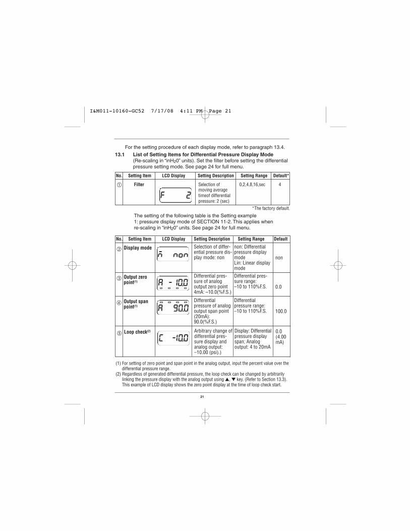
No. Setting Item LCD Display Setting Description Setting Range Default*
Filter Selection of 0,2,4,8,16,sec 4moving averagetimeof differentialpressure: 2 (sec)
*The factory default.
f00002
For the setting procedure of each display mode, refer to paragraph 13.4.
13.1 List of Setting Items for Differential Pressure Display Mode (Re-scaling in “inH20” units). Set the filter before setting the differential pressure setting mode. See page 24 for full menu.
non
The setting of the following table is the Setting example 1: pressure display mode of SECTION 11-2. This applies when re-scaling in “inH20” units. See page 24 for full menu.
No. Setting Item LCD Display Setting Description Setting Range Default
n00nonSelection of differ-ential pressure dis-play mode: non
non: Differentialpressure displaymodeLin: Linear displaymode
Display mode-
-
0.0
a0-10.0Differential pres-sure of analogoutput zero point4mA: –10.0(%F.S.)
Differential pres-sure range: –10 to 110%F.S.
Output zeropoint(1)
100.0
Differentialpressure of analogoutput span point(20mA):90.0(%F.S.)
Differentialpressure range:–10 to 110%F.S.
Output spanpoint(1)
a0-90.0
0.0(4.00mA)
Arbitrary change ofdifferential pres-sure display andanalog output:–10.00 (psi).)
Display: Differentialpressure displayspan; Analogoutput: 4 to 20mA
Loop check(2)
[0-10.0
(1) For setting of zero point and span point in the analog output, input the percent value over thedifferential pressure range.
(2) Regardless of generated differential pressure, the loop check can be changed by arbitrarilylinking the pressure display with the analog output using , key. (Refer to Section 13.3).This example of LCD display shows the zero point display at the time of loop check start.
I&M011-10160-GC52 7/17/08 4:11 PM Page 21

22
non
13.2 Setting Items for Linear Display Mode (Re-scaling in arbitrary user defined units) Set the filter before setting the linear display mode (Refer to the preceding Section 11.1). The setting of the following tableis the Setting example 2: Linear display mode of Section 11.3.(Arbitrary unit: m). This applies when re-scalingin arbitrary user defined units. See page 24 for full menu.
No Setting Item LCD Display Setting Description Setting Range Default
n00l0nSelection of lineardisplay mode: Lin
non: Differentialpressure displaymode; Lin: Lineardisplay mode
Display mode- -
0.0
p0 -20Min. differentialpressure corre-sponding to OFF-SET :20.0(inH2O)
Differential pres-sure range: 0 to 75%F.S.
Min. differen-tial pressure(1)
100.0 Max. differentialpressure corre-sponding to FULLSCALE :120inH2O)
Differentialpressure range: 25 to 100%F.S.
Max. differen-tial pressure(1) p0-120
0 Display after deci-mal point Numberof digits:1(digit)
0,1,2,3 digitDecimal pointposition d0-001
d0-00.0
d0-50.0
0 OFFSET correspon-ding min. differentialpressure : 0.0 (m)
–1999 to 1999OFFSET
1000 FULL SCALE corre-sponding to max.differential pres-sure :50.0 (m)
–1999 to 1999FULL SCALE
a0-50.00.0 Analog output zero
point : (4mA): 0.0(%F.S.)
Max. display span:–10 to 110%F.S.
Output zeropoint(2)
a0100.0100.0 Analog output span
point : (20mA):100.0 (%F.S.)
Max. display span:–10 to 110%F.S.
Output spanpoint(2)
[0-50.00(4.0mA)
Arbitrary change oflinear display andanalog output: 50.0 (m), 20mA
Display: Linear dis-play span; Analogoutput: 4 to 20mA
Loop check(3)
I&M011-10160-GC52 7/17/08 4:11 PM Page 22

23
(1) The decimal point position is fixed for each differential pressure range. (Refer to section10,Power-on Message). The maximum differential pressure can be set from the value which is 25%F.S above theminimum differential pressure.The values under 25%F.S. cannot be increased or decreased by T, S key.
(2) For setting zero point and span point of the analog output, input the percent value over themaximum display span (between OFFSET and FULL SCALE). Its decimal point position canbe set up to one digit after the decimal point (xx.x).
(3) Regardless of whether pressure is applied or not, the loop check can be activated whichlinks the display and the output allowing the operator to arbitrarily adjust the output tocheck the system, troubleshoot etc (using the T, S keys), ref section 13.4. This exampleshows the display set to the span point.
I&M011-10160-GC52 7/17/08 4:11 PM Page 23

24
M
M
M
M
M
M
M
M
M
M
M
M
M
M
M
M
u 6.00
f 2
n non n l n
a 10.0
a 90.0
[ 1.00[ 1.00
p 20.0
p 120.0
d 1
d 0.0
d 50.0
a 0.0
a 100.0
[ 50.0
--`
-
-
Linear displaymode setting
Differential pressuredisplay mode setting
Differential pressuredisplay mode
Output spanpoint pressure
Output zeropoint pressure
Loop check(zero point)
Version display
Filter
Linear display mode
Min. pressure
(Re-scaling in ìinH 2O” units)
(Re-scaling in arbitrary user defined units)
Max. pressure
Decimal pointposition
OFFSET
Full scale
Output zeropoint
Output spanpoint
Loop check(span point)
Basic key operationThe setting item is changed by M key.The set value is changed or selected by key or key. When changing the value,it is increased or decreased by pressing key or key, respectively.(Refer to next page)
key for morethan 3 seconds
Setting Mode Measurement Mode
13.3 Setting Procedure (Setting Examples from 13.1, 13.2)
I&M011-10160-GC52 7/17/08 4:11 PM Page 24

25
CheckTerminals
13.4 Loop CheckIn each display mode, regardless of applied pressure, the loop check canbe changed by arbitrarily linking the display with the analog output usingthe key operation. The display will show representative pressure readingscorrelating to the 4-20mA signal. Loop check method
(1) Remove the lid of this product.(2) Shift to either the Differential Pressure or the Linear Display Mode.
(See Section 13.1 or 13.2). Use (M) button to scroll to Loop Checkfunction as indicated within Section 13.1 or 13.2 respectively. The dis-play and output (4mA) are at the zero point when loop check starts.
(3) If the T is pressed, the display will increase along with the output. By pressing S key, decrease will occur. Release the key at the desired indication.For example, if the key is released at 25.0m, the display will stop andbe held at analog output 12mA corresponding to the indication, ref.example from section 13.2
Analog Output Check TerminalsWhen the front cover is removed, the analog output check terminals(pad: CH+, CH–) are visible at the upper part of the display substrate.The analog output can be checked during measurement mode or loopcheck by applying a probe, such as a tester for current measurement,onto the check terminal of the substrate, as shown in the following figure.In addition, receivers are not affected by the tester's probes.
Loop check / linear display
I&M011-10160-GC52 7/17/08 4:11 PM Page 25

26
Dimensions in inches
1.0
4.49
3.62
2.91
2.28
4.72
5.12
1.97
2.36
.69
2 x Ø .06Drain
4 x Ø .22Panel Mounting Holes Bracket t = .08
Ø 2
.56
.42
2.07
Drain Outlet
Equalizing Valve
High Pressure Port1/4 NPT femaleLow Pressure Port
1/4 NPT female
.82
1.42
Electrical Connection PG 13.5 threaded housing, factory installed options include cable gland or 1/2 FNPT conduit connection
inH2OGC52
14. DIMENSIONAL DRAWINGS
I&M011-10160-GC52 7/17/08 4:11 PM Page 26

27
15. MAINTENANCE AND WARRANTY Periodic inspection
Depending upon the type of use periodic inspection is recommeded atleast once a year. Please refer to the following items for periodic in-spection.
(1) Appearance(2) Display/output check via appropriate pressure standard(1)
(3) Display/output check via Loop Check(2)
CAUTION• Avoid electrostatic charging. When cleaning this product, please use
a soft, damp, cloth.
• Do not use thinner, etc. which may cause deterioration and failure.
Product warrantyExcept as otherwise provided, the product warranty of this product isas follows:
Period: 12 months after delivery
Warrantable defects: Defects resulting from the design and manufac-ture of our company, the quality of the material, etc.
Implementation of warranty: This warranty will be completed by substi-tution or repair of the product concerned.
We will not take responsibility for consequential damages caused byproduct defects.
• If you have any questions about this document, please contact thesales office or distributor nearest you.
• This document is subject to change without notice due to upgrade etc.
(1) If zero correction is required refer to section 12.
(2) Loop check, see section 13.4.
I&M011-10160-GC52 7/17/08 4:11 PM Page 27

28
© 2007 Ashcroft Inc. 250 East Main Street, Stratford, CT 06614 USATel: 203-378-8281, Fax: 203-385-0402, www.ashcroft.com All sales subject to standard terms and conditions of sale.I&M011-10160 -7/10/08
I&M011-10160-GC52 7/17/08 4:11 PM Page 28