installation and mounting instructions wmi-100 · installation and mounting instructions ... amo...
TRANSCRIPT

AMO AutomatisierungM Oesstechnik ptik GmbH
Installation andMounting Instructions
Induktives Winkelmesssystem Inductive Angle Measuring System
®AMOSIN
Montageanleitung
WMI-100

Conformity to EMC guidelines guaranteed:
The WMI-100 angle measuring system complies with corresponding standards and electromagnetic compatibility guidelines. Compliance is substantiated by the following standards:
EN 61000-4-4 (1995): Inspection of interference immunity to fast, transient, electrical interference variables / Burst EMC - Severity 4EN 61000-4-2 (1995): Interference immunity to electrostatic discharge / ESD - ECM - Severity 4EN 55011: Limits and measuring methods for radio interference from industrial, scientific and medical high-frequency devices and equipment (ISM devices)
Safety:The measures recommended in this manual for the installation and mounting of the measuring system must be complied with. Disregard of this information may give rise to unsafe operating situations and/or damage. Warranty claims shall not be accepted in such cases!
Care:The WMI-100 angle measuring system and its associated products are high-grade precision components and must therefore be handled with appropriate care.
Warranty:AMO Automatisierung Messtechnik Optik GmbH shall grant a warranty period of 24 months from the date of delivery on the components of the WMI-100 angle measuring systems. Incorrect operation or assembly/installation, unsatisfactory or incorrect electrical connection, operation outside the specified limits, tampering with electronic or mechanical systems by unauthorized personnel or modifications to components shall invalidate all warranty claims.
Product changes:AMO Automatisierung Messtechnik Optik GmbH reserves the right to make changes to and to improve the technical data of the components described in this manual.
2
WMI-100 Angle Measuring System in accordance with the AMOSIN measuring principleÜbereinstimmung mit EMV-Richtlinien:
Das Winkelmesssystem WMI-100 stimmt mit den entsprechenden Normen und Richtlinien der elektromagnetischen Verträglichkeit überein. Dies wurde gemäß folgender Normen geprüft:
EN 61000-4-4 (1995): Prüfung der Störfestigkeit gegen schnelle transiente elektrische Störgrößen / Burst EMV - Schärfegrad 4EN 61000-4-2 (1995): Störfestigkeit gegen die Entladung statische Elektrizität / ESD - EMV - Schärfegrad 4EN 55011: Grenzwerte und Messverfahren für Funkstörungen von industriellen, wissenschaftlichen und medizinischen Hochfrequenzgeräten (ISM-Geräten) - Störaussendung
Sicherheit:Die in diesem Handbuch empfohlenen Maßnahmen für die Installation und den Montagevorgang des Messsystems sind unbedingt zu beachten. Bei Missachtung können unsichere Bedienung bzw. Schäden auftreten. In diesen Fällen erlischt der Anspruch auf Gewährleistung!
Sorgfalt:Das Winkelmesssystem WMI-100 und die dazugehörigen Produkte sind hochwertige Präzisionsbauteile und müssen daher mit dementsprechender Sorgfalt behandelt werden.
GewährleistungAMO Automatisierung Messtechnik Optik GmbH gewährt auf die Komponenten des Winkelmesssystems WMI-100 eine Gewährleistungszeit von 24 Monaten ab Lieferdatum. Bei falscher Bedienung oder Montage, unzureichender oder falscher elektrischer Anschlüsse, Betrieb außerhalb der spezifizierten Grenzen, Eingriffe in die Elektronik oder Mechanik durch nicht autorisiertes Personal oder Änderung der Komponenten erlischt der Anspruch.
Produktänderung:AMO Automatisierung Messtechnik Optik GmbH behält sich vor, jederzeit die technischen Daten der in diesem Handbuch beschriebenen Komponenten zu verändern und zu verbessern.
WMI-100 Winkelmesssystem nach dem AMOSIN Prinzip
WMI-1003
Allgemeinesgeneralities
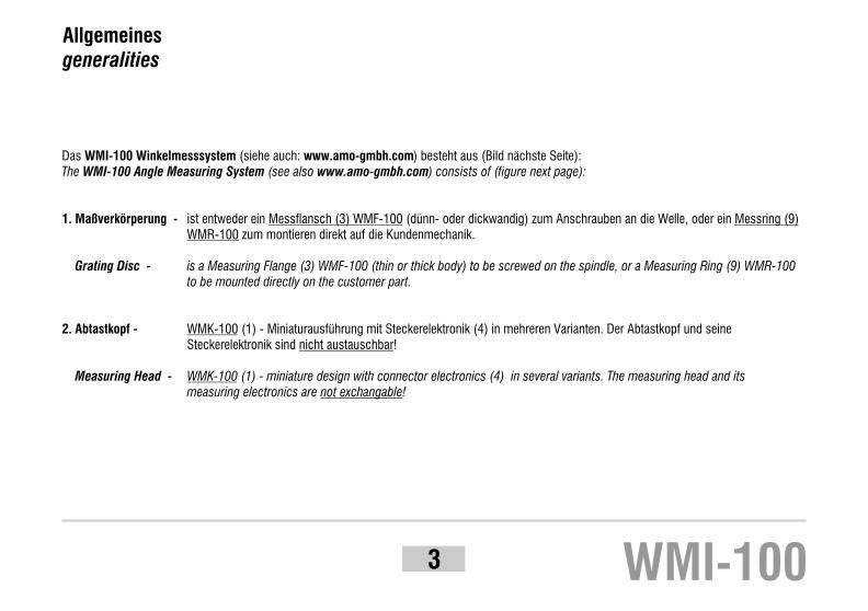
Das WMI-100 Winkelmesssystem (siehe auch: www.amo-gmbh.com) besteht aus (Bild nächste Seite):The WMI-100 Angle Measuring System (see also www.amo-gmbh.com) consists of (figure next page):
1. Maßverkörperung - ist entweder ein Messflansch (3) WMF-100 (dünn- oder dickwandig) zum Anschrauben an die Welle, oder ein Messring (9)WMR-100 zum montieren direkt auf die Kundenmechanik.
Grating Disc - is a Measuring Flange (3) WMF-100 (thin or thick body) to be screwed on the spindle, or a Measuring Ring (9) WMR-100to be mounted directly on the customer part.
2. Abtastkopf - WMK-100 (1) - Miniaturausführung mit Steckerelektronik (4) in mehreren Varianten. Der Abtastkopf und seineSteckerelektronik sind nicht austauschbar!
Measuring Head - WMK-100 (1) - miniature design with connector electronics (4) in several variants. The measuring head and its measuring electronics are not exchangable!

4
Abtastkopf WMK-100Scanning head WMK-100Abstandsfolie 0,15 mmSpacer film 0.15mmMessflansch WMF-100Measuring flange WMF-100Signalkonditionierung in Stecker integriertSignal conditioning integrated in connectorMontageanleitungMounting instructionsPrüfzertifikatTest certificateMessprotokoll (Option)Calibration chart (optional)Verlängerungskabel VK 4 (Option)Extension cable VK 4 (optional)Messring WMR-100 (alternativ zu WMF-100)Measuring ring WMR-100 (alternative to WMF-100)
1.
2.
3.
4.
5.
6.
7.
8.
9.
items suppliedLieferumfang
1
3
9
4

Abmessungen / dimensions
WMI-1005

6
Standard Messflansch WMF-100 / Standard Measuring Flange WMF-100
Type / TypeWMF-100 -
Æ A (mm) Æ B (mm) bÆ I (mm)
WMF-100 WMF-101
Teilungsgenauigkeit*grating accuracy
0360-0
0512-0
0720-0
0900-0
0360-1
0512-1**
0720-1**
0900-1**
1024-0
1024-1**
115.07
115,07
163,54
163,54
229,78
229,78
287,08
287,08
326,55
326,55
75
105
120
153
195
219
195
276
235
311
6 x 60°
6 x 60°
6 x 60°
12 x 30°
12 x 30°
60+0- 0,01
+0- 0,01
+0- 0,01
+0- 0,01
+0- 0,01
+0- 0,01
95
143
180
209
180
266
220
296
105
+0- 0,01
+0- 0,01
+0- 0,01
+0- 0,01
± 36"
± 24"
± 18"
± 14"
± 12"
0256-1 81,27 70 6 x 60°+0- 0,0160
± 18"
± 12"
± 9"
± 7"
± 6"
± 25"± 50"
*
**
Höhere Genauigkeiten auf
Anfrage.
Für die Messsystemausführung
mit doppelter diametraler
Abtastung (zwei Abtastköpfe)
wird die Messgenauigkeit um den
Faktor 2 erhöht.
Higher precision figures by
request.
The precision of measurement is
increased by a factor of 2 in the
measuring system implementati-
on that uses double diametral
scanning (two scanning heads).
Nur für Presspassungsmontage
auf Kundenwelle (Toleranzemp-
fehlung der Welle )
Only for press fitting on the
customer spindle. (spindle
Diameter tolerance )
+ 0,01+ 0,02
+ 0,01+ 0,02

7
Messring WMR-100 / Measuring Ring WMR-100
* Rundlaufempfehlung
Höhere Rundlaufwerte bis ~0,05 mm haben keinen Einfluss auf die
Funktionen des Gerätes, beeinträchtigen aber verhältnismäßig die
Positioniergenauigkeit.
! Breite 10 mm! Ausdehnungskoeffizient: ~11 ppm! Flanschmaterial: kein spezielles Material notwendig! ØF: Durchmesser des Flansches ohne Maßverkörperung! ØS: Durchmesser der Anschlagschulter
! Width 10 mm! Coefficient of expansion: ~11 ppm! Flange material: no special material is required! ØF: diameter of the flange without the measuring ring! ØS: diameter of the stop collar * Recommended concentricity
Greater eccentricities of up to ~0.05 mm do not affect the function of
the device, but do cause a proportionate deterioration in the accuracy of
positioning.
WMI-100
Assembly drawing:
Anschlussmaße Messring WMR - Trägerflansch
(Empfehlung):

8
N: ganzzahlige Anzahl der Teilstriche pro Umdrehung (1 Teilstrich = 1 mm Bogenlänge)
N: integral number of grating pitches per revolution (1 pitch = 1 mm arc length)
ØF: Durchmesser des Flansches ohne Maßverkörperung
ØF: diameter of the flange without the measuring ring
N= 256 bis/to 511
N= 512 bis/to 719
N= 720 bis/to 1024
N= 1025 bis/to 1500
N= 1501 bis/to 2000
N= 2001 bis/to 3000
N= 3001 bis/to 4000
ØF = N/P - 0,82 ±0,01 [mm]
ØF = N/P - 0,73 ±0,02 [mm]
ØF = N/P - 0,70 ±0,02 [mm]
ØF = N/P - 0,68 ±0,03 [mm]
ØF = N/P - 0,65 ±0,06 [mm]
ØF = N/P - 0,62 ±0,07 [mm]
ØF = N/P - 0,60 ±0,10 [mm]
Standard Messringe im Lieferprogramm:: WMR-10 - ... 0256, 0360, 0512, 0720, 0900, 1024, 1440, 2048
Weitere Strichzahlen werden auf Anfrage angeboten.
Standard program measuring rings: WMR-10 - ... 0256, 0360, 0512, 0720, 0900, 1024, 1440, 2048
Further sizes can be made by request.

9
Handhabung / handling
Achtung:Die Außenfläche des Messflansches und die Abtastfläche des Messkopfes sind empfindlich gegen mechanische Beanspruchung.Während des ganzen Montagevorganges müssen diese Flächen gegen mechanische Beschädigungen geschützt werden.
Messring nicht knicken!
Caution:The outer surface of the measuring flange and the scanning surface of the measuring head are sensitive to mechanical stress and strain.These surfaces must be protected against mechanical damage during the entire mounting and installation procedure.
Do not buckle the measuring ring!
!
WMF-100
WMK-100
WMR-100
WMI-100

10
Montage Messflansch WMF-100 / mounting Measuring Flange WMF-100
M5
Md < 6 Nm
M6
Md < 10,5 Nm
Die Achsenrundlaufabweichungen beeinträchtigen die Messgenauigkeit negativ und sollen auf ein Minimum eingestellt werden (z.B. eine Rundlaufabweichung von 1µm entspricht für einen Flansch mit Außendurchmesser 200 mm einem Winkelfehler von etwa zwei Winkelsekunden).Radial runout has a negative effect on measuring accuracy and should therefore be set to a minimum (e.g. for a flange with an outside diameter of 200mm, a radial runout of 1µm corresponds to an angle error of about two arc seconds).
Der Messflansch kann sowohl von der Rückseite mit M6 Schrauben als auch von der Vorderseite mit M5 Schrauben an der Messachse befestigt werden. Der Messflansch wird entweder mit Spiel oder leichter Presspassung an die Spindel montiert.The measuring flange can be secured to the measuring spindle both from the rear with M6 screws as well as from the front with M5 screws. The measuring flange is mounted on the spindle either with play or slight press-fit.
Die axiale und radiale Montageflächen des Messflansches müssen unmittelbar vor der Montage gereinigt werden.The axial and radial mounting surfaces of the measuring flange must be cleaned right before assembly.

11 WMI-100
Messflanschzentrierung WMF-100 centring Measuring Flange WMF-100
Achtung:Es darf keinesfalls mit metallischen Gegenständen auf den Messflansch geschlagen werden!
Caution:Never hit the measuring flange with metal objects!
!
Zum Erreichen der maximalen Achsengenauigkeit muß der Messflansch ideal auf die Achse zentriert werden.The measuring flange must be centred precisely with respect to the axis in order to achieve maximum accuracy.
Der Messflansch weist an der Messfläche Zylindrizitäts- und Konzentrizitätsabweichungen kleiner als 5µm zur Innenfläche auf.Hier werden kleine Winkelbereiche nicht berücksichtigt (funktionell nicht von Bedeutung), wo eventuell diese Toleranz überschritten wird (z.B. Stoßstelle des Schutzbandes).The measuring surface of the measuring flange exhibits cylindricity and concentricity deviations with respect to the inner surface of less than 5µm.Here, small angle ranges are not taken into consideration (of no functional significance) wherever this tolerance may be exceeded (e.g. joint of protective band.)

12
Montage Messring WMR-100mounting Measuring Ring WMR-100
Der Messring wird mit einer Presspassung auf einem entsprechenden Flansch angebracht (Zeichnungsempfehlung siehe www.amo.at) und bildet die Maßverkörperung des Messsystems.The measuring ring has to be mounted over a press fitting on the apropriate flange (see recommended drawing on www.amo.at).
Der Rundlauf des Systems ist maßgeblich für die Systemgenauigkeit und muss auf ein Optimum justiert werden.The radial runout has a great influence on the accuracy; be sure that it is optimally adjusted.
Der Messring besteht aus drei Edelstahlfolien, einem blanken Trägerring (1), einem Gitterring mit Referenzfenster und Messteilung (2) und einem Abdeckring als Schutzband (3) (Bild 1).The measuring ring consists of three concentric rings of stainless steel, a carrier ring (1), a grating ring (2) and a protection ring (3) (fig. 1).
Achtung:Der Gitterring als Maßverkörperung ist Teil eines Messgerätes und muss während der Montagearbeiten mit größter Sorgfalt behandelt werden.Caution:The grating ring must be handeled very carefully during the entire mounting procedure.
!
1. Allgemeines / generalities
Bild 1

13 WMI-100
"
"
"
A temperature of 20 +/- 5°C must be kept during the entire mounting process.
Die vorgesehene Montagefläche für den Messring ist nach Tabelle oder nach AMO Anforderung gefertigt und geprüft und innerhalb der angegebenen Toleranz (siehe Zeichnung Seite 7; ansonsten ist die Montagefähigkeit nicht gewährleistet).Check that the mounting surface for the ring corresponds with the drawing on page 7.
Die Auflagefläche für den Messring ist feingedreht, gratfrei und entfettet.The mounting surface has the prescripted roughness and is free of dirt.
Die Messringe haben einen thermischen Ausdehnungskoeffizienten von ~11 ppm. Für große Durchmesser oder bedeutendeTemperaturschwankungen im Betrieb sollte die relative Temperaturausdehnung Messring - Messsubstrat (Flansch, z.B. Aluminium ~23 ppm) berücksichtigt werden. Die Montage erfolgt bei einer Temperatur von 20 +/- 5 °C.The ring elongation coefficient is ~11 ppm. For large diameters or high temperature oscillations, the difference between the elongation coefficient of ring and mounting flange (for example, aluminium ~ 23 ppm) must be considered.
Achtung - während der ganzen Montage bitte beachten:
1. Messring nicht in seine drei Komponenten zerlegen.
2. Ringe nicht knicken.3. Besonderes Augenmerk auf die
lasergeschweissten Stoßstellen und dieReferenzmarke(n).
4. Auspacken nur in sauberer Umgebung.5. Montageanleitung sorgfältig lesen.
! Caution
1. Do not dismount the measuring ring into itsthree components.
2. Don’t buckle the rings.3. Give special care to the rings laserwelded joint
points and the reference mark slot.4. Unpack the system in a clean environment.5. Read the mounting instruction carefully.
!
2. Vorraussetzungen für die Montage des Messsystems / mounting conditions

14
3. Standardmontage (gesamter Messring aufgezogen) Standard mounting method (entire measuring ring fitting)
3.1. Messring aus der Verpackung entnehmen und auf eine saubere Fläche auflegen.Unpack the measuring ring carefully in a clean place.
Empfehlung: Zur Montageerleichterung kann der Messring erwärmt bzw. der Flansch abgekühlt werden.
Recommendation: For a light fitting of the ring, the measuring flange can becooled down or the ring warmed up.
Achtung Große Messringe unter keinen Umständen an der Stoßstelle tragen.
KNICK- oder BRUCHGEFAHR
CautionHandle with care. Don’t carry the ring at its joint points!
BUCKLE RISK
!
Bild 2
Bild 3

15 WMI-100
3.2. Die Auflagefläche für das Gitterband am Flansch sorgfältig reinigen.Clean up the mounting surface.
3.3 Den Messring so wie angeliefert im zusammengebauten Zustand mit allen drei Ringen, waagerecht, bis ca. 5mmder Ringauflagefläche am Flansch, im Umfang von etwa 180°, so um den Trägerbandstoß (Bild 4) am Messring ansetzen, dass die Referenzmarke ihre gewünschte Position am Flansch erhält. Place the ring as delivered with the mark of the reference point at the desired angular location and fitt it lightly on the flange for about half the circumference and about 5mm depth.
--
Bild 4 Bild 5

16
Gegenüber, wo der Messring am Flansch aufliegt, wird die mitgelieferte Stahlfolie alsMontagehilfe zwischen Messring und Flanschkante eingelegt (Bilder 5 und 6). Nun kannder Messring vorsichtig über den ganzen Umfang des Flansches aufgezogen werden.Place the thin delivered foil between ring and flange as shown in fig.6 and pressthe ring over the whole circumference of the flange.
3.4. Hier sollte noch einmal kontrolliert werden, ob die Position der RI Marke mit derFlanschposition übereinstimmt. Falls diese nicht in der gewünschten Genauigkeitübereinstimmt, wird der Messring abgezogen und die letzten Vorgänge wiederholt.Check that the mark on the ring for the reference point is in coincidence with thedesired position. If it’s not, repeat the instructions 3.1 to 3.4.
3.5. Die eingeklemmte Stahlfolie wird mit einer Flachzange nach unten herausgezogen.Pull out the thin foil between ring and flange with a pair of flat pliers.
Bild 7
3.6 Nun wird der Messring in kleinen Hüben in gleichmäßiger Tiefe rundherum händisch odermit Hilfe eines halbweichen Kunststoffklotzes nach unten geschoben, bis er an derAuflageschulter aufliegt.Now use a plastic pad to press the ring around the flange in small steps until it reachesthe stop shoulder of the flange.
Bild 6

17
3.7. Es wird überprüft, ob alle Messringfolien mit ihren Kanten fluchtend und übereinstimmend fest an dem Schulteranschlag des Flansches liegen.Falls die untere Stahlfolie (Trägerring) beim Aufziehen etwas zurückgeblieben ist, wird diese mit einem Aluminium- oder Kunststoffklotz, ohnemechanische Beschädigung, entsprechend nachgezogen.Check that all three rings overlap properly. If they don’t, correct the position carefully without causing any mechanical damage.
Achtung:Die axiale Lage des Messrings, in allen seinen Teilen und Kanten übereinstimmend, in festem Kontakt mit der Flansch-Anschlagschulter, ist entscheidend für das Erreichen einer hohen Genauigkeit.Caution:Check the exact perpendicularity of the ring with the rotation axis over its whole circumference. That is very important to grant the specified accuracy.
!
3.8. Rundlauf prüfen bzw. auf ein Minimum einstellen.Check the runout and adjust it at a minimum. That is a basic requirement to reach high accuracies.
WMI-100

4. Alternativmethode Messringmontage (Messringkomponenten einzeln aufgezogen) Alternative mounting method (components of the measuring ring mounted separatly)
Falls sich durch eine zu enge Passung Flansch-Messring eine Montage des Messrings im zusammengebauten Zustand als zu schwierig erweist, kann dieser in seine einzelnen Bestandteile (Ringe) auseinander genommen und so in mehreren Schritten auf den Flansch aufgezogen werden.If it is difficult to mount the entire measuring ring, caused by too tight fitting of flange and ring, the measuring ring can be disassembled and its components mounted separatly.
Achtung:Der Abdeckring als dünne Folie (0,05mm) darf nicht von dem Gitterring getrennt werden!Caution:Do not separate the protection ring (a thin foil of 0,05 mm) from the grating ring!
!
4.1 Messring in seine einzelnen Teile zerlegen / disassembling the measuring ring! Messring waagerecht in sauberer Umgebung auf den Montagetisch auflegen.
Place the measuring ring horizontal on a clean surface.! Messring gegenüber der Trägerringstoßstelle (Bild 8) vorsichtig nach innen drücken,
bis sich der Trägerring vom Gitterring durch einen “Schnappeffekt” ablöst (Bild 9).Carefully pull the measuring ring inwards opposite the reference point mark, till carrier ring and grating ring sever (fig. 8, 9)
! Trägerring vollständig vom Gitterring trennen.Separate completely carrier ring and grating ring.
Bild 8
Bild 9
18

4.2 Trägerring aufziehen / carrier ring mountingWie unter Punkt 3.1 beschrieben, beginnend mit der Stoßstelle, bis zur Anschlagschulter auf den Flansch aufziehen.Pull the carrier ring over the whole circumference of the flange as described in 3.1.
4.3 Gitterring aufziehen / grating ring mountingMit Abdeckring zusammen, unter Berücksichtigung der Referenzpunktlage gegenüber dem Flansch (Bild 5), über den Trägerring, bis zur Anschlagschulter (wie unter Punkt 3.1 beschrieben) aufziehen.Now pull the grating ring together with the protection ring over the carrier ring as described in 3.1. Mind the reference mark.
4.4 Rundlaufgenauigkeit prüfen bzw. auf ein Minimum einstellen.Check the runout and adjust it at a minimum. That is a basic requirement to reach high accuracies.
19
Achtung:Die axiale Lage des Messrings, in allen seinen Teilen und Kanten übereinstimmend, in festem Kontakt mit der Flansch-Anschlagschulter, ist entscheidend für das Erreichen einer hohen Genauigkeit.Caution:Check the exact perpendicularity of the ring over the whole circumference with the rotation axis. That is very important to grant the specified accuracy.
!
WMI-100
20
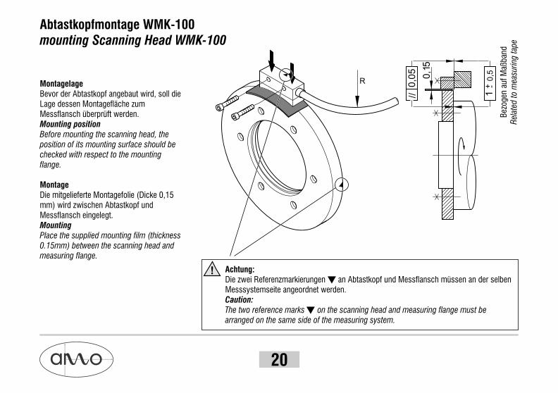
Abtastkopfmontage WMK-100mounting Scanning Head WMK-100
MontagelageBevor der Abtastkopf angebaut wird, soll die Lage dessen Montagefläche zum Messflansch überprüft werden.Mounting positionBefore mounting the scanning head, the position of its mounting surface should be checked with respect to the mounting flange.
MontageDie mitgelieferte Montagefolie (Dicke 0,15 mm) wird zwischen Abtastkopf und Messflansch eingelegt.MountingPlace the supplied mounting film (thickness 0.15mm) between the scanning head and measuring flange.
Achtung:Die zwei Referenzmarkierungen an Abtastkopf und Messflansch müssen an der selben Messsystemseite angeordnet werden.Caution:The two reference marks on the scanning head and measuring flange must be arranged on the same side of the measuring system.
!
0,1
//0
,05
10
,5+ -
R
5
Bez
ogen
auf
Maß
band
Rel
ated
to
mea
suri
ng t
ape

21
Der Abtastkopf wird leicht und gleichmäßig gegen den Messflansch angedrückt, sodass der Innenradius des Abtastkopfes sich dem Außenradius des Messflansches anpasst (selbst zentrierender Effekt). Unter diesem leichten Druck können jetzt die Schrauben befestigt werden.Weiters wird mit der Montagefolie geprüft, ob der Abtastabstand für die ganze Abtastfläche gleich eingestellt wurde (leichter Widerstand beim Einschieben der Folie zwischen Abtastkopf und Messflansch, gleichmäßig für die ganze Fläche). Falls der Abstand nicht gleichmäßig ist, wiederholt sich der Vorgang (ev. Abstand von Montagebohrungen zum Messflansch überprüfen).
Lightly and evenly press the scanning head against the measuring flange so that the inner radius of the scanning head is aligned with the outer radius of the measuring flange (self-centring effect). The screws can now be tightened while still applying this slight pressure.The assembly film is further used to check whether the scanning distance is set evenly over the entire scanning surface (slight resistance is felt when inserting the film between the scanning head and measuring flange, uniform over the entire surface). If the spacing is not uniform, repeat the procedure (if necessary, check the distance from the mounting holes to the measuring flange).
ErdungDie zwei Montageschrauben des Abtastkopfes dienen auch als Verbindung des Elektronikgehäuses zur Maschinenerde.EarthingThe two mounting screws of the scanning head serve as the connection of the electronic module to the machine earth.
!
SchutzWährend der Montage und im Betrieb dürfen keine Festkörperpartikel in den Luftspalt zwischen Abtastkopf und Messflansch eintreten.ProtectionThere must be no solid particles in the air gap between the scanning head and measuring flange during assembly and operation.
!
WMI-100

22
Steckerelektronik - WMK-100connection electronics - WMK-100

23
Technische Daten: Abtastkopf WMK-10 / technical data: Scanning Head WMK-10
-10°C bis 100°C (höhere Temperaturen auf Anfrage)-10° to 100° C (higher temperatures by request)
-20°C bis 85°C-20°C to 85°C
Abtastkopf: IP67Steckerelektronik / Ausführungen mit CONNEI-Kupplung: Ip67 Steckerelektronik / Ausführungen mit 15 pol. SUB-D Stecker: IP54
Scanning head: IP 67Connector electronics / versions with CONNEI connector: IP 67 Connector electronics / version with 15-pin Sub-D connector: IP 54
5V ±5% am Gerät (Sensorleitungen vorhanden), 1 Vss Ausgang: 260mA / TTL Ausgang: 300 mA 5V ±5% at the device (with sensor lines present), 1 Vpp Output: 260mA / TTL output: 300 mA
PUR Mantel, hochflexibel, Ø 5,3 mm, 5(2 x 0,05) + 1 (2 x 0,14) mm²(Biegeradius: 10 x d = 50 mm Dauerbiegung; 5 x d = 25 mm Einmalbiegung)
PUR jacket, high flexibility, dmr. 5.3 mm, 5(2x0.05) + 1 (2x0.14) mm²(Bending radius: 10 x d = 50mm continuous bending; 5 x d = 25mm single bend)
! WMK-101. Ausgang analog 1 Vss an Abschlusswiderstand 120 W mit Sinussignalperiode von 1000 µm oder 1000 µm/D
! WMK-102. Ausgang TTL - Auflösungen laut folgender Tabelle
! WMK-101. analog output 1 Vpp to 120 W terminating resistor with sinus output of 1000 µm or 1000 µm/D
! WMK-102. TTL output - resolution as in the following table
W
W
Arbeitstemperatur:Operating temperature:
Lagertemperatur:Storage temperature:
Schutzklasse:
Protection class:
Versorgung:
Power supply:
Kabel:
Cable:
Ausgangssignale:
Output signals:
WMI-100
Max. Drehzahlen: siehe folgende FrequenztabelleMax. speed: see the following frequency table

24
WMK-101.1
WMK-101.2
WMK-101.SO
WMK-102.0
WMK-102.1
WMK-102.4
WMK-102.5
WMK-102.6
WMK-102.7
WMK-102.A
WMK-102.B
Ausgangs-
signal
output
signal
1 Vss
1 Vss
1 Vss
TTL
TTL
TTL
TTL
TTL
TTL
TTL
TTL
Unterteilungsfaktor
dividing factor
(1)D(1)D
-
10 µm
5 µm
1 µm
0,25 µm
50 µm
25 µm
62,5 µm
31,25
25x /
50x /
250x /
1000x /
5x /
10x /
4x /
8x /
Maximale Eingangs-
frequenz f [kHz]
max. input
frequency f [kHz]
10(3)80(3)100
20
10
2,5
40
(3)80
Typ
type
(2)Interpolationsfaktor / Auflösung
(2)interpolationfactor / resolution
0256 0360 0512 0720 0900 1024
Drehzahl n [U/min] / rotary speed n [rpm]
18400 12800 8800 6400 5120 4400
9200 6400 4400 3200 2560 2200
575 400 225 200 160 130
2300 1600 1100 800 640 550
4600 3200 2200 1600 1280 1100
23000 17500 11500 8000 6500 5750
18400 12800 8800 6400 5120 4400
2300 1600 1100 800 640 550
Standardmessflansch WMF-10 bzw. Messringe WMR-10
standard measuring flange WMF-10 or measuring ring WMR-10
(1), (2), (3) siehe nächste Seite / see next page

25
Ansonsten gilt / Otherwise, the following applies:
• Maximale Drehzahl / Max. Speed: n [U/min] = f [Hz] x 60 / N (Teilstriche/U) N ... Teilstriche (1mm am Umfang Messflansch) / Umdrehungmax
n [rpm] = f [Hz] x 60 / N (grating pitches/revolution)max
N … grating pitches (1 mm, at the circumference of the measuring flange) / revolution
• Ausgangsfrequenz fa (Grenzfrequenz der Folgeelektronik) / Output frequency fa (frequency limit for the subsequent electronics) (1)WMK-101: fa = f x D [kHz] D ... analoger Unterteilungsfaktor / analog dividing factor (D = 1/4/8/10/25/32)
(2)WMK-102: fa = f x I [kHz] I ... digitaler Interpolationsfaktor / digital interpolation factor (I = 4/5/8/10/25/50/250/1000)
Fa ist begrenzt mit 400 kHz für 1 Vss Ausgang | fa ... limited with 400 kHz for 1 Vpp
(3) Höhere Eingangsfrequenzen auf AnfrageHigher input frequencies by request.
WMI-100
26
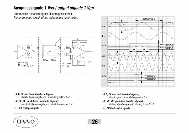
• A, B, RI (and their inverted signals):direct signal output, dividing factor D=1
• A´, B´, Ri´ (and their inverted signals):divided signal output with dividing factor D=1
• LL, LR limit switch signals
Ausgangssignale 1 Vss / output signals 1 Vpp
Empfohlene Beschaltung der Nachfolgeelektronik:Recommended circuit of the subsequent electronics:
• A, B, RI (und deren invertierte Signale): direkte Signalausgabe mit Unterteilungsfaktor D=1
• A´, B´, Ri´ (und deren invertierte Signale):unterteilte Signalausgabe mit Unter teilungsfaktor D=1
• LL, LR Endlagensignale

27 WMI-100
Ausgangssignale TTL RS422output signals TTL - RS422
Empfohlene Beschaltung der Nachfolgeelektronik:Recommended circuit of the subsequent electronics:
Ausgabe-Signalperiode 360° el.Output period 360° el.
Flankenabstand / Phase shift 90° ±45°
Signal Diagramm:Signal diagram:

28
CONNEI-Typ Stecker bzw. Kupplung 12-polig - Metallkörper kunststoffummanteltCONNEI- connector adv. coupling 12-pin - plastic-coated metal body
Sinus- 1 Vss oder Rechteck-Ausgangssignale TTLSine-wave 1 Vpp or Square-wave output signals TTL
Die Sensorleitungen 0V-Sensor und 5V-Sensor sind intern mit den entsprechenden Versorgungsleitungen verbunden. Diese dienen zur Überprüfung bzw. Nachregelung der Spannung am Gerät und können auch parallel zu den Versorgungsleitungen 0V und 5V verwendet werden, um somit den Spannungsabfall der Leitung zu verringern.
Falls die Option Endlage nicht vorhanden ist dürfen die zwei Leitungen LL und LR nicht an die Folgeelektronik (z.B. Steuerung) angeschlossen werden.Diese Leitungen dienen nur für Testzwecke in Verbindung mit dem AMO-Testgerät STU-20.
„ “ „ “ „ “
Steckerbelegungen / plug and connection assignments
The sensor lines 0V sensor and 5V sensor are connected internally to the corresponding supply lines. They serve the purpose of checking and readjusting the supply voltage at the device and can also be used parallel to the 0V and 5V supply lines for the purpose of reducing the voltage drop in the line.
In case that the option "Limit Switch" is not used, it is not allowed to connect the pins "LL" and "LR" to the following electronics (for example controller). These pins serve alone for test purposes only with the AMO testdevice STU-20.
StiftseitePin side
StiftseitePin side
9 1
2
3
45
6
7 12
8
11
10
51
26
28
Schirm am Gehäuse / shield on housing
PIN
Signal
1
B-
2 3 4 5 6 7 8 9 10 11 12
0VA+ A- B+RI+ RI- +5V
Farbbelegung blaugrün gelb braunrosa grau rotweiss
5V-Sensor
rot-weiss
LL
violett
LR
schwarz
0V-Sensor
blau-weiss
26
53
25
.5
M 2
3x1
9 8
7
6
54
3
2 10
1
11
12
SteckerConnector Kupplung
Coupling
Color bluegreen yellow brownpink gray redwhite red-white violet black blue-white

29 WMI-100
SUB-D Stecker 15-polig / SUB-D connector 15-pin
Sinus- 1 Vss oder Rechteck-Ausgangssignale TTL / Sine-wave 1 Vpp or Square-wave output signals TTL
Schirm am Gehäuse / shield on housing
1
B-
2 3 4 5 6 7 8 9 10 11 12
0VA+ LRB+ — RI-+5V
PIN
Signal
Farbbelegung blaugrün schwarzbraun graurot weiss—
39.2
13
4 5
12
321
11109
6 7 8
13 14 15
A-
gelb
LL
violett
RI+—
rosa—
—
—
13 14 15
0V-Sensor
blau-weiss
5V-Sensor
rot-weiss
Falls die Option Endlage nicht vorhanden ist dürfen die zwei Leitungen LL und LR nicht an die Folgeelektronik (z.B. Steuerung) angeschlossen werden.Diese Leitungen dienen nur für Testzwecke in Verbindung mit dem AMO-Testgerät STU-20.
„ “ „ “ „ “
Color bluegreen blackbrown greyred white— yellowviolet pink— —blue-white red-white
In case that the option "Limit Switch" is not used, it is not allowed to connect the pins "LL" and "LR" to the following electronics (for example controller).These pins serve alone for test purposes only with the AMO testdevice STU-20.
—
DIN Stecker 12-polig L120 / DIN connector 12-pin L120
PIN
Signal
A B C D E F G H J K L M
0V A+ A- B+ — RI+ RI- — —+5V B- 18
42
70
StiftseitePin side
KA
J
H
B
L CM
GF
ED
—Farbbelegung blau grün gelb braun — rosa grau — —rot weiss
Schirm am Gehäuse / shield on housing
—Color blue green yellow brown — pink grey — —red white
Sinus- 1 Vss oder Rechteck-Ausgangssignale TTL / Sine-wave 1 Vpp or Square-wave output signals TTL

30
30.8
13
4 5
9
321
876
SUB-D Stecker 9-polig / SUB-D connector 9-pin
PIN
Signal
1
B-
2 3 4 5 6 7 8 9
0V A+A- B+ RI+RI-— +5V
Farbbelegung blau grüngelb braun rosagrau— rotweiss
Sinus- 1 Vss oder Rechteck-Ausgangssignale TTL / Sine-wave 1 Vpp or Square-wave output signals TTL
Schirm am Gehäuseshield on housingColor blue greenyellow brown pinkgrey— redwhite

WMI-10031
Notizen

© 2007 - MEDIA-LINE, Grafik & Mediengestaltung, Braunau / SN: WMI-100-MA-20071028
AMO AutomatisierungM Oesstechnik ptik GmbH
Tech
nisc
he Ä
nder
unge
n vo
rbeh
alte
n. /
Tec
hnic
al D
ata
are
subj
ect
to c
hang
e w
ithou
t no
tice.
Für nähere Informationen wenden Sie sich bitte an:For more detailed information please contact:
A-4963 St. Peter am Hart, Nöfing 4
Telefon/phone: +43/7722/658 56-0Fax: +43/7722/658 56-11
e-mail: [email protected]: www.amo-gmbh.com