installation and operating manual - unternehmen
TRANSCRIPT
Installation and Operating ManualNGI-1000 Digital Ignition System
Form NGI-1000 IOM 10-17
NGI-1000 IOM 10-17 All rights reserved © ALTRONIC, LLC 2017 2
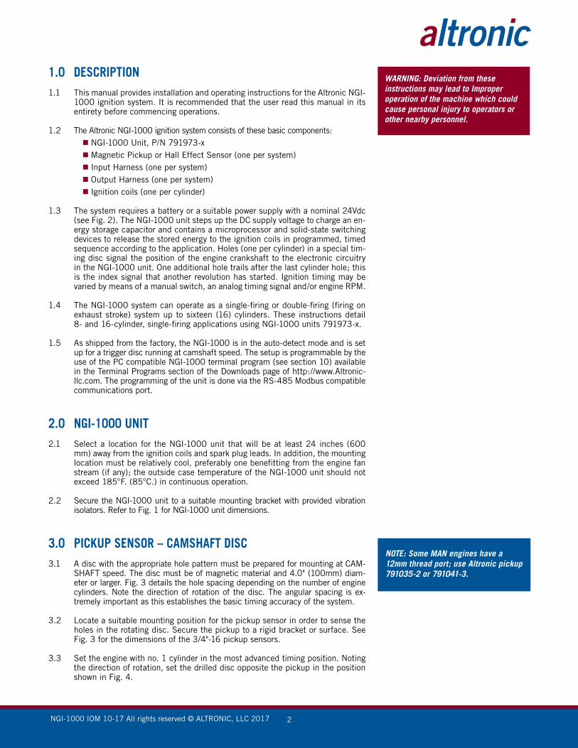
1.0 DESCRIPTION1.1 This manual provides installation and operating instructions for the Altronic NGI-
1000 ignition system. It is recommended that the user read this manual in its entirety before commencing operations.
1.2 The Altronic NGI-1000 ignition system consists of these basic components: NGI-1000 Unit, P/N 791973-x Magnetic Pickup or Hall Effect Sensor (one per system) Input Harness (one per system) Output Harness (one per system) Ignition coils (one per cylinder)
1.3 The system requires a battery or a suitable power supply with a nominal 24Vdc (see Fig. 2). The NGI-1000 unit steps up the DC supply voltage to charge an en-ergy storage capacitor and contains a microprocessor and solid-state switching devices to release the stored energy to the ignition coils in programmed, timed sequence according to the application. Holes (one per cylinder) in a special tim-ing disc signal the position of the engine crankshaft to the electronic circuitry in the NGI-1000 unit. One additional hole trails after the last cylinder hole; this is the index signal that another revolution has started. Ignition timing may be varied by means of a manual switch, an analog timing signal and/or engine RPM.
1.4 The NGI-1000 system can operate as a single-firing or double-firing (firing on exhaust stroke) system up to sixteen (16) cylinders. These instructions detail 8- and 16-cylinder, single-firing applications using NGI-1000 units 791973-x.
1.5 As shipped from the factory, the NGI-1000 is in the auto-detect mode and is set up for a trigger disc running at camshaft speed. The setup is programmable by the use of the PC compatible NGI-1000 terminal program (see section 10) available in the Terminal Programs section of the Downloads page of http://www.Altronic-llc.com. The programming of the unit is done via the RS-485 Modbus compatible communications port.
2.0 NGI-1000 UNIT2.1 Select a location for the NGI-1000 unit that will be at least 24 inches (600
mm) away from the ignition coils and spark plug leads. In addition, the mounting location must be relatively cool, preferably one benefitting from the engine fan stream (if any); the outside case temperature of the NGI-1000 unit should not exceed 185°F. (85°C.) in continuous operation.
2.2 Secure the NGI-1000 unit to a suitable mounting bracket with provided vibration isolators. Refer to Fig. 1 for NGI-1000 unit dimensions.
3.0 PICKUP SENSOR – CAMSHAFT DISC
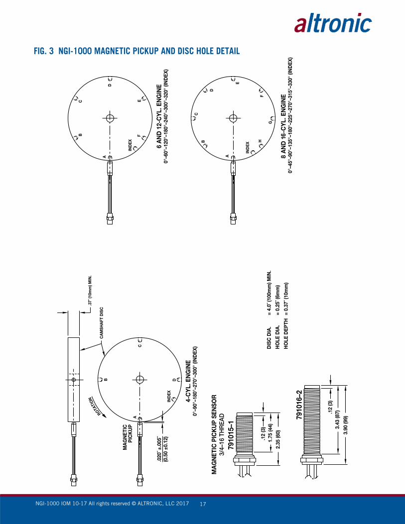
3.1 A disc with the appropriate hole pattern must be prepared for mounting at CAM-SHAFT speed. The disc must be of magnetic material and 4.0" (100mm) diam-eter or larger. Fig. 3 details the hole spacing depending on the number of engine cylinders. Note the direction of rotation of the disc. The angular spacing is ex-tremely important as this establishes the basic timing accuracy of the system.
3.2 Locate a suitable mounting position for the pickup sensor in order to sense the holes in the rotating disc. Secure the pickup to a rigid bracket or surface. See Fig. 3 for the dimensions of the 3/4"-16 pickup sensors.
3.3 Set the engine with no. 1 cylinder in the most advanced timing position. Noting
the direction of rotation, set the drilled disc opposite the pickup in the position shown in Fig. 4.
NOTE: Some MAN engines have a 12mm thread port; use Altronic pickup 791035-2 or 791041-3.
WARNING: Deviation from these instructions may lead to Improper operation of the machine which could cause personal injury to operators or other nearby personnel.
NGI-1000 IOM 10-17 All rights reserved © ALTRONIC, LLC 2017 3
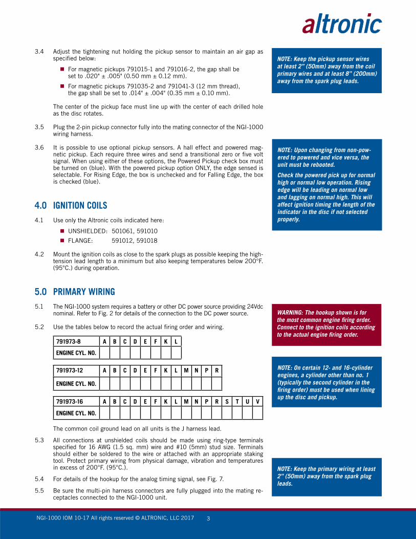
3.4 Adjust the tightening nut holding the pickup sensor to maintain an air gap as specified below:
For magnetic pickups 791015-1 and 791016-2, the gap shall be
set to .020" ± .005" (0.50 mm ± 0.12 mm).
For magnetic pickups 791035-2 and 791041-3 (12 mm thread), the gap shall be set to .014" ± .004" (0.35 mm ± 0.10 mm).
The center of the pickup face must line up with the center of each drilled hole as the disc rotates.
3.5 Plug the 2-pin pickup connector fully into the mating connector of the NGI-1000 wiring harness.
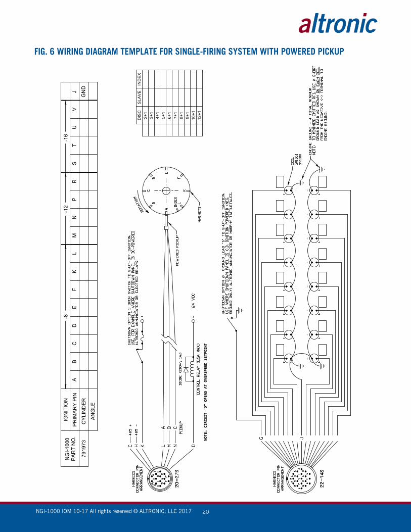
3.6 It is possible to use optional pickup sensors. A hall effect and powered mag-netic pickup. Each require three wires and send a transitional zero or five volt signal. When using either of these options, the Powered Pickup check box must be turned on (blue). With the powered pickup option ONLY, the edge sensed is selectable. For Rising Edge, the box is unchecked and for Falling Edge, the box is checked (blue).
4.0 IGNITION COILS4.1 Use only the Altronic coils indicated here:
UNSHIELDED: 501061, 591010
FLANGE: 591012, 591018
4.2 Mount the ignition coils as close to the spark plugs as possible keeping the high-tension lead length to a minimum but also keeping temperatures below 200°F. (95°C.) during operation.
5.0 PRIMARY WIRING5.1 The NGI-1000 system requires a battery or other DC power source providing 24Vdc
nominal. Refer to Fig. 2 for details of the connection to the DC power source.
5.2 Use the tables below to record the actual firing order and wiring.
791973-8 A B C D E F K L
ENGINE CYL. NO.
791973-12 A B C D E F K L M N P R
ENGINE CYL. NO.
791973-16 A B C D E F K L M N P R S T U V
ENGINE CYL. NO.
The common coil ground lead on all units is the J harness lead.
5.3 All connections at unshielded coils should be made using ring-type terminals specified for 16 AWG (1.5 sq. mm) wire and #10 (5mm) stud size. Terminals should either be soldered to the wire or attached with an appropriate staking tool. Protect primary wiring from physical damage, vibration and temperatures in excess of 200°F. (95°C.).
5.4 For details of the hookup for the analog timing signal, see Fig. 7.
5.5 Be sure the multi-pin harness connectors are fully plugged into the mating re-ceptacles connected to the NGI-1000 unit.
NOTE: Keep the pickup sensor wires at least 2” (50mm) away from the coil primary wires and at least 8” (200mm) away from the spark plug leads.
NOTE: Upon changing from non-pow-ered to powered and vice versa, the unit must be rebooted.
Check the powered pick up for normal high or normal low operation. Rising edge will be leading on normal low and lagging on normal high. This will affect ignition timing the length of the indicator in the disc if not selected properly.
WARNING: The hookup shown is for the most common engine firing order. Connect to the ignition coils according to the actual engine firing order.
NOTE: On certain 12- and 16-cylinder engines, a cylinder other than no. 1 (typically the second cylinder in the firing order) must be used when lining up the disc and pickup.
NOTE: Keep the primary wiring at least 2” (50mm) away from the spark plug leads.
NGI-1000 IOM 10-17 All rights reserved © ALTRONIC, LLC 2017 4
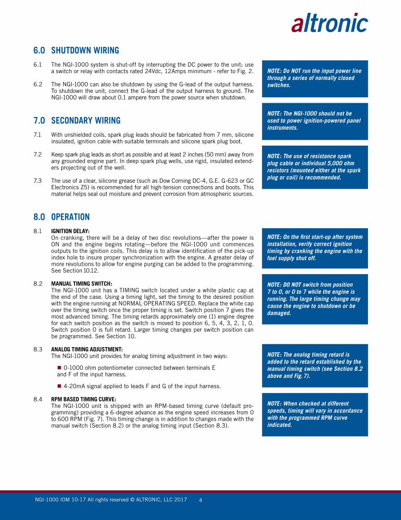
6.0 SHUTDOWN WIRING6.1 The NGI-1000 system is shut-off by interrupting the DC power to the unit; use
a switch or relay with contacts rated 24Vdc, 12Amps minimum - refer to Fig. 2.
6.2 The NGI-1000 can also be shutdown by using the G-lead of the output harness. To shutdown the unit, connect the G-lead of the output harness to ground. The NGI-1000 will draw about 0.1 ampere from the power source when shutdown.
7.0 SECONDARY WIRING7.1 With unshielded coils, spark plug leads should be fabricated from 7 mm, silicone
insulated, ignition cable with suitable terminals and silicone spark plug boot. 7.2 Keep spark plug leads as short as possible and at least 2 inches (50 mm) away from
any grounded engine part. In deep spark plug wells, use rigid, insulated extend-ers projecting out of the well.
7.3 The use of a clear, silicone grease (such as Dow Corning DC-4, G.E. G-623 or GC Electronics Z5) is recommended for all high-tension connections and boots. This material helps seal out moisture and prevent corrosion from atmospheric sources.
8.0 OPERATION8.1 IGNITION DELAY: On cranking, there will be a delay of two disc revolutions—after the power is
ON and the engine begins rotating—before the NGI-1000 unit commences outputs to the ignition coils. This delay is to allow identification of the pick-up index hole to insure proper synchronization with the engine. A greater delay of more revolutions to allow for engine purging can be added to the programming. See Section 10.12.
8.2 MANUAL TIMING SWITCH: The NGI-1000 unit has a TIMING switch located under a white plastic cap at
the end of the case. Using a timing light, set the timing to the desired position with the engine running at NORMAL OPERATING SPEED. Replace the white cap over the timing switch once the proper timing is set. Switch position 7 gives the most advanced timing. The timing retards approximately one (1) engine degree for each switch position as the switch is moved to position 6, 5, 4, 3, 2, 1, 0. Switch position 0 is full retard. Larger timing changes per switch position can be programmed. See Section 10.
8.3 ANALOG TIMING ADJUSTMENT: The NGI-1000 unit provides for analog timing adjustment in two ways:
0-1000 ohm potentiometer connected between terminals E and F of the input harness.
4-20mA signal applied to leads F and G of the input harness.
8.4 RPM BASED TIMING CURVE: The NGI-1000 unit is shipped with an RPM-based timing curve (default pro-
gramming) providing a 6-degree advance as the engine speed increases from 0 to 600 RPM (Fig. 7). This timing change is in addition to changes made with the manual switch (Section 8.2) or the analog timing input (Section 8.3).
NOTE: Do NOT run the input power line through a series of normally closed switches.
NOTE: The NGI-1000 should not be used to power ignition-powered panel instruments.
NOTE: The use of resistance spark plug cable or individual 5,000 ohm resistors (mounted either at the spark plug or coil) is recommended.
NOTE: On the first start-up after system installation, verify correct ignition timing by cranking the engine with the fuel supply shut off.
NOTE: DO NOT switch from position 7 to 0, or 0 to 7 while the engine is running. The large timing change may cause the engine to shutdown or be damaged.
NOTE: The analog timing retard is added to the retard established by the manual timing switch (see Section 8.2 above and Fig. 7).
NOTE: When checked at different speeds, timing will vary in accordance with the programmed RPM curve indicated.
NGI-1000 IOM 10-17 All rights reserved © ALTRONIC, LLC 2017 5
9.0 CUSTOMIZING THE NGI-1000 UNIT9.1 Through the use of the PC terminal display, customizing the NGI-1000 ignition
module is possible. The NGI-1000 takes advantage of the patented Varispark technology as well as maintains the ability to have a traditional CD spark. Once in the terminal display the secondary energy can be modified to optimize engine per-formance. The process is intuitive and straight forward as the units are displayed as mA (current in the spark) and uS (length of the spark in microseconds).
9.2 SPARK CURRENT: When setting the spark current this can either be a traditional CD spark, or a Va-
rispark both operating at 185V DC. Using the dropdown window a list of currents is available. As displayed, each mA value describes the current in the spark. Any value with a “+” sign provides the mA value initially and rises at a linear rate over the length of time selected in the next step.
9.3 SPARK DURATION: To set the spark duration a second drop down menu is available. Each spark
length is depicted in uS and is matched with the spark current. The NGI-1000 will hold the selected spark current for the duration, or length, for up to a maxi-mum of 250W.
9.4 ENGINE PERFORMANCE: It is important to tailor the spark current and duration to the engine demands.
By applying the best spark profile, it will help to ensure that the spark plug wear and engine performance meet expectations. Things to take into consideration are spark plug interval changes, spark plug kV at end of life, and the demand of the spark plug over the entire engine load. It is recommended to monitor for engine misfire at all load conditions and tune the spark as necessary, using the current and duration menus. Higher current short duration profiles will generate a lot of initial energy to ignite a poor gas mixture. While a longer duration spark will help to keep a mixture lit longer into the rotation cycle.
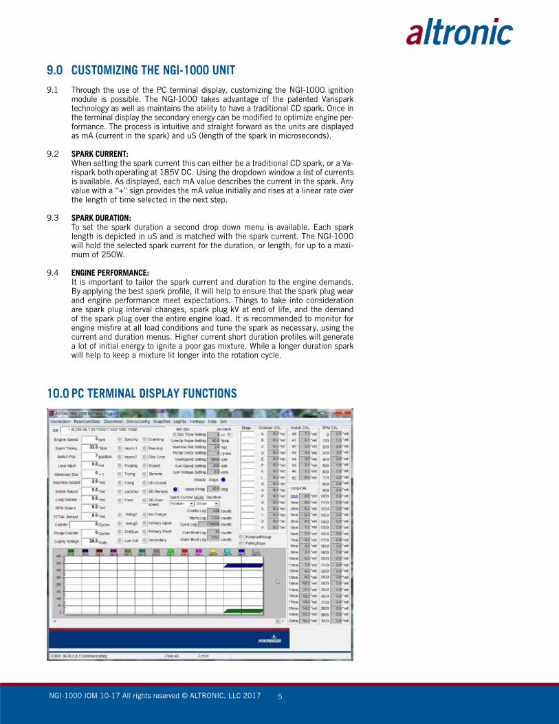
10.0 PC TERMINAL DISPLAY FUNCTIONS
NGI-1000 IOM 10-17 All rights reserved © ALTRONIC, LLC 2017 6
10.1 ENGINE SPEED: Indicates current speed of the engine in RPM based on disc signal.
10.2 SPARK TIMING: Indicates the global spark timing of the engine in degrees before TDC. This
number is the LINE UP ANGLE setting less the TOTAL RETARD. Slight differ-ences between this number and the timing reading obtained with a timing light may occur since the LINE UP ANGLE entered may differ slightly from the actual angular position of the engine when the input pulse event is received by the NGI-1000. In this event, the Spark Timing number should be made to agree with the timing light by changing the LINE UP ANGLE entry.
10.3 SWITCH POSITION: Indicates the current position of the manual timing switch on the NGI-1000 case.
10.4 LOOP INPUT: Indicates the value of the external input current loop.
10.5 OBSERVED DISC: Indicates the number of input events (timing holes or protrusions) being recog-
nized by the NGI-1000 unit on the timing disc input signal at this time.
10.6 INSERTION RETARD: Indicates the amount of electronic insertion retard at this time.
10.7 SWITCH RETARD: Indicates the amount of timing retard being added by the current timing switch
position at this time.
10.8 LOOP RETARD: Indicates the actual amount of timing retard added from the current loop versus
retard lookup table curve at this time.
10.9 RPM RETARD: Indicates the actual amount of timing retard being added by the RPM versus
retard lookup table curve at this time.
10.10 TOTAL RETARD: Indicates the total global timing retard at this time. This number is the sum of
the Insertion Retard, Switch Retard, Loop Retard and RPM Retard.
10.11 COUNTER: Indicates the number of disc rotations (engine cycles) registered since the en-
gine was last started.
10.12 PURGE COUNTER: During a startup, indicates the number of purge cycles remaining before the
outputs are activated.
10.13 SUPPLY VOLTAGE: Indicates the measured DC voltage supply level to the NGI-1000.
10.14 SPARK REF. (A, B, C, ETC.): Indicates the current spark reference number for each cylinder.
10.15 SYNCING: When red, indicates that engine rotation has been sensed and the synchroniza-
tion process is taking place.
10.16 INSYNC1: When red, indicates that the index input has been recognized once.
10.17 INSYNC2: When red, indicates that the index has been recognized a second time and the
ignition is ready to proceed.
10.18 PURGING: When red, indicates that synchronization has been completed and the purge
cycle countdown is taking place.

NGI-1000 IOM 10-17 All rights reserved © ALTRONIC, LLC 2017 7
10.19 TRYING: When red, indicates that the NGI-1000 is trying to fire outputs, but a proper
primary discharge event has not yet occurred.
10.20 FIRING: When red, indicates that NGI-1000 is successfully firing primary outputs.
10.21 LOCKOUT: When red, indicates that firings are locked out until engine rotation has ceased
for a minimum of 5 seconds.
10.22 CRANKING: When red, indicates engine rotation below the Run Speed setting.
10.23 RUNNING: When red, indicates engine rotation above the Run Speed setting.
10.24 DISC ERROR: When red, indicates that the Test Disc status flag is activated and the timing
disc pattern being sensed did not match the DISC TYPE selected.
10.25 G-LEAD: When red, indicates that the G-lead is grounded.
10.26 REMOTE: When red, indicates a remote serial shutdown command is active.
10.27 SD-LEAD: When red, indicates that a shutdown has occurred which was the result of a
grounded G-lead condition.
10.28 SD-REMOTE: When red, indicates that a shutdown has occurred as a result of a remote serial
shutdown command.
10.29 SD-OVERSPEED: When red, indicates that a shutdown has occurred as a result of the engine
reaching the Overspeed setting.
10.30 WDOG1: When red, indicates that the microprocessor has re-booted since the ignition
has been powered-up.
10.31 WDOG2: When red, indicates that the microprocessor is currently re-booting. Disregard
the first blink when first connecting.
10.32 CHKSUM: When red, indicates a software checksum failure of the unit’s firmware.
10.33 LOW VOLT: When red, indicates that the input DC voltage is at or below the Low Voltage
setting input.
10.34 NO CHARGE: When red, indicates that the primary storage capacitor has failed to charge
properly within the last ~2 seconds.
10.35 PRIMARY OPEN: When red, indicates that an open primary condition has been detected within
the last ~2 seconds.
10.36 PRIMARY SHORT: When red, indicates that a shorted primary condition has been detected within
the last ~2 seconds.
10.37 SECONDARY OPEN: When red, indicates that an open secondary condition has been detected within
the last ~2 seconds.

NGI-1000 IOM 10-17 All rights reserved © ALTRONIC, LLC 2017 8
10.38 CRANKS LOG: Indicates the total number of crank attempts seen by the NGI-1000.
10.39 STARTS LOG: Indicates the total number of successful starts seen by the NGI-1000 as defined
by the Run Speed setting input.
10.40 CYCLE LOG: Total number of engine cycles seen by the NGI-1000.
10.41 COLD BOOT LOG: Indicates the number of times the input DC voltage has been cycled to zero.
10.42 WARM BOOT LOG: Indicates the number of times the microprocessor has restarted without a com-
plete loss of power.
10.43 GRAPHIC DISPLAY: The NGI-1000 Terminal Software provides a real time graphic display of the
secondary diagnostic numbers, global engine timing (y-axis /10) and en-gine speed (y-axis x 10).
10.44 POWERED PICKUP: Selectable for Hall effect or Powered Magnetic Pickup option. Turns blue when
activated.
10.45 FALLING EDGE: Selectable when using Powered Pickup. Turns blue when using Falling Edge.
11.0 NGI-1000 UNIT LED DIAGNOSTIC BLINK CODES11.1 NGI-1000 IGNITION BLINK CODES: Whenever the LED Diags status flag is enabled (blue) by using the NGI-1000
Terminal Software, the blinking pattern of the LED on the side of the NGI-1000 case can be used to interpret the general status of the NGI-1000 diagnostics without the use of the Terminal Software. Within each group of conditions de-scribed below, the possible diagnostic states are listed according to their num-ber of blinks. The LED is ON for about 2 seconds between each blink sequence and the blinks occur evenly spaced at a faster rate.
11.2 LED SIGNALS WITH THE ENGINE STOPPED:
ON – STEADY = READY (new power up or last start attempt aborted)
ON – 1 BLINK – ON = FIRED LAST TIME ROTATING (stopped due to stall)
ON – 2 BLINK – ON = SHUTDOWN (by grounding G-LEAD when running)
ON – 3 BLINK – ON = SHUTDOWN (by remote serial request when running)
ON – 4 BLINK – ON = SHUTDOWN (by overspeed when running)
ON – 5 BLINK – ON = WRONG DISK PATTERN
ON – 6 BLINK – ON = LOW SUPPLY VOLTAGE (below threshold when running)
11.3 LED SIGNALS WITH ENGINE CRANKING (rotating, and still below running RPM):
ON/OFF/ON/OFF = PURGING (off first input pulse, toggles each revolution of purge)
ON – STEADY = FIRING NORMALLY (RPM below running set point value)
OFF = WRONG DISC PATTERN DETECTED
11.4 LED SIGNALS WITH ENGINE RUNNING (when firing, and above run speed):
ON – STEADY = FIRING NORMALLY (no diagnostics to report)
ON – 1 BLINK – ON = OPEN SECONDARY ALARM
ON – 2 BLINK – ON = PRIMARY SHORT ALARM
ON – 3 BLINK – ON = PRIMARY OPEN ALARM
NOTE: Check the polarity of powered pickup for normal high or normal low operation. Ignition timing can be affected.
NGI-1000 IOM 10-17 All rights reserved © ALTRONIC, LLC 2017 9
ON – 4 BLINK – ON = NO CHARGE ALARM
ON – 6 BLINK – ON = LOW SUPPLY VOLTAGE
12.0 RS-485 COMMUNICATIONS, MODBUS RTU12.1 The NGI-1000 is compliant to the Modbus RTU standard. Maximum number
of registers that can be read at one time is limited to 32. Maximum number of booleans that can be read at one time is limited to 256. All communications are 8 data bits, no parity, 1 stop bit. The baud rate is 9600. The MODBUS address list follows:
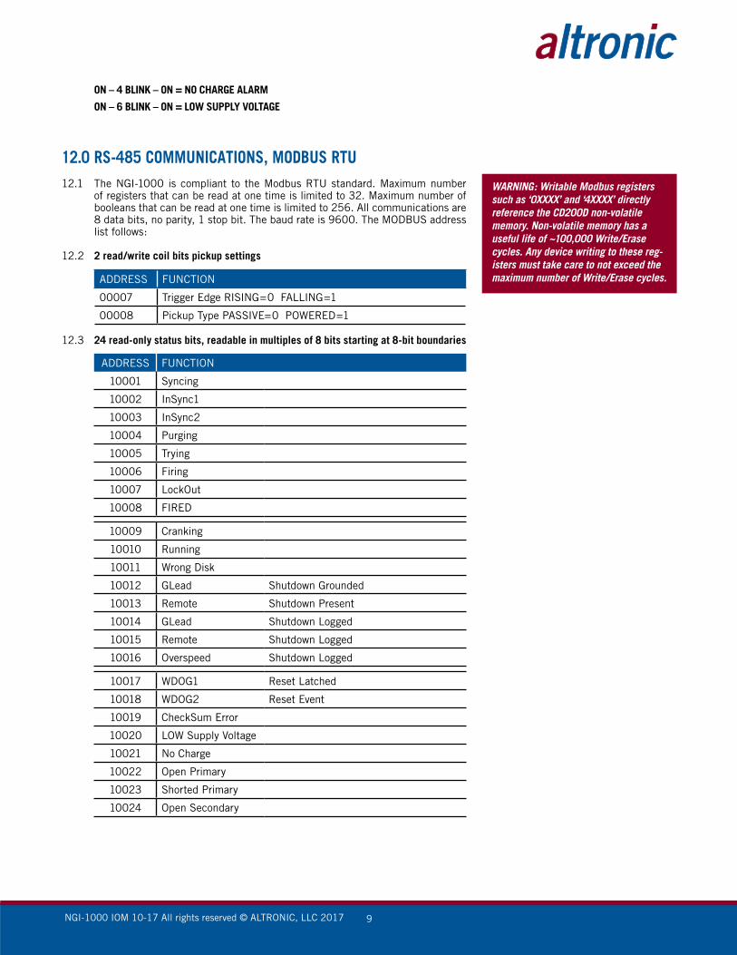
12.2 2 read/write coil bits pickup settings
ADDRESS FUNCTION
00007 Trigger Edge RISING=0 FALLING=1
00008 Pickup Type PASSIVE=0 POWERED=1
12.3 24 read-only status bits, readable in multiples of 8 bits starting at 8-bit boundaries
ADDRESS FUNCTION
10001 Syncing
10002 InSync1
10003 InSync2
10004 Purging
10005 Trying
10006 Firing
10007 LockOut
10008 FIRED
10009 Cranking
10010 Running
10011 Wrong Disk
10012 GLead Shutdown Grounded
10013 Remote Shutdown Present
10014 GLead Shutdown Logged
10015 Remote Shutdown Logged
10016 Overspeed Shutdown Logged
10017 WDOG1 Reset Latched
10018 WDOG2 Reset Event
10019 CheckSum Error
10020 LOW Supply Voltage
10021 No Charge
10022 Open Primary
10023 Shorted Primary
10024 Open Secondary
WARNING: Writable Modbus registers such as ‘0XXXX’ and ‘4XXXX’ directly reference the CD200D non-volatile memory. Non-volatile memory has a useful life of ~100,000 Write/Erase cycles. Any device writing to these reg-isters must take care to not exceed the maximum number of Write/Erase cycles.

NGI-1000 IOM 10-17 All rights reserved © ALTRONIC, LLC 2017 10
12.4 Read-only status registers
ADDRESS FUNCTION
30001 Input Bit Mirror 10016–10001
30002 Input Bit Mirror 10032–10017
30003 Input Bit Mirror 10048–10033
30004 Input Bit Mirror 10064–10049
30005 RPM
30006 Timing xxx.xDEG signed
30007 Switch Position 1–8
30008 Current Loop Input xx.xmA
30009 Disk Observed X+1
30010 Insertion Retard xxx.xDeg
30011 Switch Retard xxx.xDeg
30012 Loop Retard xxx.xDeg
30013 RPM Retard xxx.xDeg
30014 Total Retard xxx.xDeg
30015 Cycle Counter HI
30016 Cycle Counter LO xx.xVolts
30017 Supply Voltage
30018 Spark Ref. Num. Output A
30019 Spark Ref. Num. Output B
30020 Spark Ref. Num. Output C
30021 Spark Ref. Num. Output D
30022 Spark Ref. Num. Output E
30023 Spark Ref. Num. Output F
30024 Spark Ref. Num. Output K
30025 Spark Ref. Num. Output L
30026 Spark Ref. Num. Output M
30027 Spark Ref. Num. Output N
30028 Spark Ref. Num. Output P
30029 Spark Ref. Num. Output R
30030 Spark Ref. Num. Output S
30031 Spark Ref. Num. Output T
30032 Spark Ref. Num. Output U
30033 Spark Ref. Num. Output V
30034 Purge Delay Index Down Counter
30035 Distributor MUX code 0–15
30036 KEYCOMMAND
30037 Period Predivider
30038 Period MS16BITS
30039 Period LS16BITS
30040 FireStat:DelayStat

NGI-1000 IOM 10-17 All rights reserved © ALTRONIC, LLC 2017 11
12.5 8 read/write configuration bits, supports write single only, readable in multiples of 8 bits starting at 8 bit boundaries
ADDRESS FUNCTION
1 DISK ON CAM=0 CRANK=1
2 TEST FOR PROPER DISK YES=1
3 ENABLE SECONDARY DIAGS YES=1
4 RESERVED
5 RESERVED
6 SLAVE
7 reserved
8 OFF = MAGNETIC Pickup ON = HALL-EFFECT Pickup
12.6 4 read/write registers mirror coil bits
ADDRESS FUNCTION
40001 REG40001=CoilBits 00016-00001
40002 REG40002=CoilBits 00032-00017
40003 REG40003=CoilBits 00048-00033
40004 REG40004=CoilBits 00064-00049
12.7 8 read/write registers regarding application
ADDRESS FUNCTION
40005 Disk+1 2,3,4,5,6,7,8,9,10,12
40006 Disk Lineup to TDC xx.x DEG
40007 Insertion Ret MIN=2.0 DEG xx.x
40008 Purge Delay Cycles 0-255
40009 RPM Over Speed Setpoint
40010 RPM Crank to Run Threshold
40011 Low Supply Voltage Limit xx.xV
40012 SLAVE ANGLE xx.x DEG
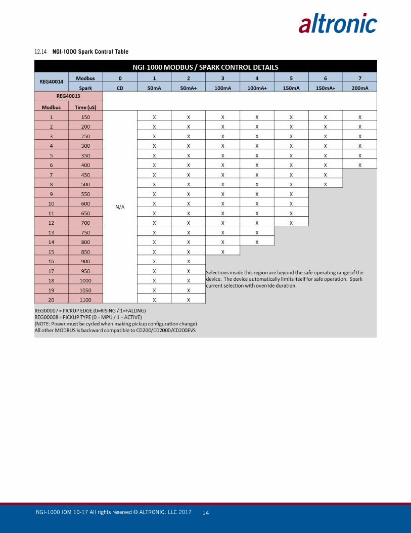
12.8 2 read/write registers for spark control
ADDRESS FUNCTION
40013 Spark Duration Control 200uS=0 250uS=1 … 1000uS=16
40014 Spark Current Control C.D.=0 50mA=1 50mA+=2 … 200mA=7
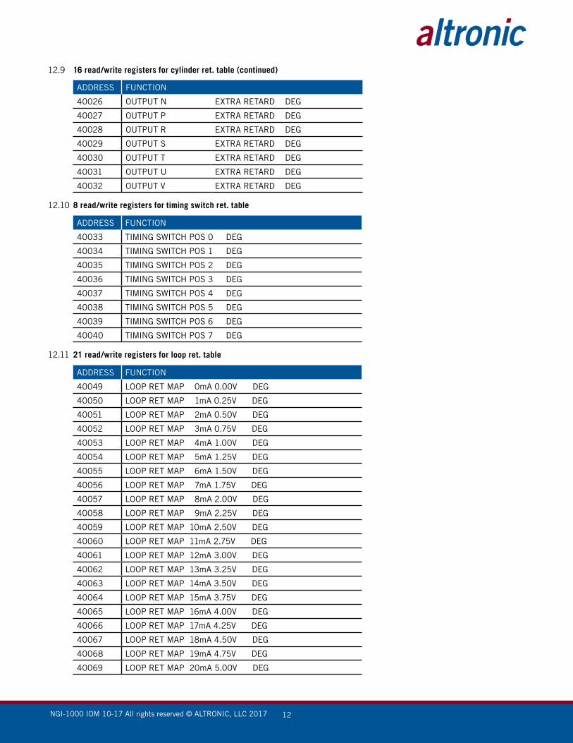
12.9 16 read/write registers for cylinder ret. table
ADDRESS FUNCTION
40017 OUTPUT A EXTRA RETARD DEG
40018 OUTPUT B EXTRA RETARD DEG
40019 OUTPUT C EXTRA RETARD DEG
40020 OUTPUT D EXTRA RETARD DEG
40021 OUTPUT E EXTRA RETARD DEG
40022 OUTPUT F EXTRA RETARD DEG
40023 OUTPUT K EXTRA RETARD DEG
40024 OUTPUT L EXTRA RETARD DEG
40025 OUTPUT M EXTRA RETARD DEG
NGI-1000 IOM 10-17 All rights reserved © ALTRONIC, LLC 2017 12
ADDRESS FUNCTION
40026 OUTPUT N EXTRA RETARD DEG
40027 OUTPUT P EXTRA RETARD DEG
40028 OUTPUT R EXTRA RETARD DEG
40029 OUTPUT S EXTRA RETARD DEG
40030 OUTPUT T EXTRA RETARD DEG
40031 OUTPUT U EXTRA RETARD DEG
40032 OUTPUT V EXTRA RETARD DEG
12.10 8 read/write registers for timing switch ret. table
ADDRESS FUNCTION
40033 TIMING SWITCH POS 0 DEG
40034 TIMING SWITCH POS 1 DEG
40035 TIMING SWITCH POS 2 DEG
40036 TIMING SWITCH POS 3 DEG
40037 TIMING SWITCH POS 4 DEG
40038 TIMING SWITCH POS 5 DEG
40039 TIMING SWITCH POS 6 DEG
40040 TIMING SWITCH POS 7 DEG
12.11 21 read/write registers for loop ret. table
ADDRESS FUNCTION
40049 LOOP RET MAP 0mA 0.00V DEG
40050 LOOP RET MAP 1mA 0.25V DEG
40051 LOOP RET MAP 2mA 0.50V DEG
40052 LOOP RET MAP 3mA 0.75V DEG
40053 LOOP RET MAP 4mA 1.00V DEG
40054 LOOP RET MAP 5mA 1.25V DEG
40055 LOOP RET MAP 6mA 1.50V DEG
40056 LOOP RET MAP 7mA 1.75V DEG
40057 LOOP RET MAP 8mA 2.00V DEG
40058 LOOP RET MAP 9mA 2.25V DEG
40059 LOOP RET MAP 10mA 2.50V DEG
40060 LOOP RET MAP 11mA 2.75V DEG
40061 LOOP RET MAP 12mA 3.00V DEG
40062 LOOP RET MAP 13mA 3.25V DEG
40063 LOOP RET MAP 14mA 3.50V DEG
40064 LOOP RET MAP 15mA 3.75V DEG
40065 LOOP RET MAP 16mA 4.00V DEG
40066 LOOP RET MAP 17mA 4.25V DEG
40067 LOOP RET MAP 18mA 4.50V DEG
40068 LOOP RET MAP 19mA 4.75V DEG
40069 LOOP RET MAP 20mA 5.00V DEG
12.9 16 read/write registers for cylinder ret. table (continued)

NGI-1000 IOM 10-17 All rights reserved © ALTRONIC, LLC 2017 13
12.12 31 read/write registers for rpm ret. table
ADDRESS FUNCTION
40070 RPM RET MAP 0000 RPM DEG
40071 RPM RET MAP 0100 RPM DEG
40072 RPM RET MAP 0200 RPM DEG
40073 RPM RET MAP 0300 RPM DEG
40074 RPM RET MAP 0400 RPM DEG
40075 RPM RET MAP 0500 RPM DEG
40076 RPM RET MAP 0600 RPM DEG
40077 RPM RET MAP 0700 RPM DEG
40078 RPM RET MAP 0800 RPM DEG
40079 RPM RET MAP 0900 RPM DEG
40080 RPM RET MAP 1000 RPM DEG
40081 RPM RET MAP 1100 RPM DEG
40082 RPM RET MAP 1200 RPM DEG
40083 RPM RET MAP 1300 RPM DEG
40084 RPM RET MAP 1400 RPM DEG
40085 RPM RET MAP 1500 RPM DEG
40086 RPM RET MAP 1600 RPM DEG
40087 RPM RET MAP 1700 RPM DEG
40088 RPM RET MAP 1800 RPM DEG
40089 RPM RET MAP 1900 RPM DEG
40090 RPM RET MAP 2000 RPM DEG
40091 RPM RET MAP 2100 RPM DEG
40092 RPM RET MAP 2200 RPM DEG
40093 RPM RET MAP 2300 RPM DEG
40094 RPM RET MAP 2400 RPM DEG
40095 RPM RET MAP 2500 RPM DEG
40096 RPM RET MAP 2600 RPM DEG
40097 RPM RET MAP 2700 RPM DEG
40098 RPM RET MAP 2800 RPM DEG
40099 RPM RET MAP 2900 RPM DEG
40100 RPM RET MAP 3000 RPM DEG
12.13 7 read/write misc. registers
ADDRESS FUNCTION
40122 Crank Counter
40123 Start Counter
40124 Cycle Counter HIGH
40125 Cycle Counter LOW
40126 REG40005 MSB=BAUD LSB=NODEID fixed 9600n81:node1
40127 Cold Boot (powerup) Count
40128 Warm Boot ( reset ) Count
NGI-1000 IOM 10-17 All rights reserved © ALTRONIC, LLC 2017 14
12.14 NGI-1000 Spark Control Table

NGI-1000 IOM 10-17 All rights reserved © ALTRONIC, LLC 2017 15
FIG. 1 NGI-1000 DIMENSIONS AND SPECIFICATIONS, 791973-X
8.85224.87.73
196.3
7.12180.0
6.25158.8
14-PIN 19-PIN
OPERATING TEMPERATURE: -40 C TO +85 C
STORAGE TEMPERATURE: -40 C TO +105 C
INPUT VOLTAGE: 24 VDC NOM.
OUTPUT VOLTAGE: 185 VDC NOM.
14-PIN CONNECTORCONN. PIN PCB HOLE
A MPAB MPBC 485 +D FLTE +5VF 4-20 ING 4-20 -H 485 -I N/CJ N/CK +24 POWER SUPPLYL POWERED PICKUP + SVM POWERED PICKUP INPUTN POWERED SUPPLY/POWERED
PICKUP GROUND

NGI-1000 IOM 10-17 All rights reserved © ALTRONIC, LLC 2017 16
FIG. 2 NGI-1000 OPERATING VOLTAGE REQUIREMENT
SU
PP
LY C
UR
RE
NT:
7.5
A
SU
PP
LY V
OLT
AG
E:
24 V
DC
BY
NU
MB
ER
OF
SY
STE
MS
.FO
R M
ULT
IPLE
SY
STE
MS
, MU
LTIP
LY R
EQ
UIR
EM
EN
TS1.
INFO
RM
ATI
ON
IS P
ER
ON
E (1
) NG
I-100
0 S
YS
TEM
.
NO
TE:
PO
WE
R S
UP
PLY
SP
EC
S: 2
5 A
MP
PE
AK
PU
LSE
S, 7
.5 A
MP
CO
NTI
NU
OU
S.
D.C
. PO
WE
R S
OU
RC
E
- -
++BA
T.
BA
T.
ALT
ER
NA
TOR
RE
GU
LATO
R
BA
T. C
HA
RG
ER
PO
WE
R S
UP
PLY
WIR
E S
IZE
: 16
GA
. (1.
5 S
Q. m
m) M
IN.
12 A
MP
FUS
E R
ATI
NG
:12
AM
P M
IN.
RA
TIN
G:
SW
ITC
H
+ -
NO
TE: H
OU
SIN
G M
US
T B
E G
RO
UN
DE
D
TO E
NG
INE
BLO
CK
.
2. P
OW
ER
SU
PP
LY N
EG
ATI
VE
MU
ST
BE
GR
OU
ND
ED
TO
EN
GIN
E B
LOC
K.
NGI-1000 IOM 10-17 All rights reserved © ALTRONIC, LLC 2017 17
FIG. 3 NGI-1000 MAGNETIC PICKUP AND DISC HOLE DETAIL

NGI-1000 IOM 10-17 All rights reserved © ALTRONIC, LLC 2017 18
FIG. 4 NGI-1000 PICKUP AND DISC INSTALLATION

NGI-1000 IOM 10-17 All rights reserved © ALTRONIC, LLC 2017 19
FIG. 5 WIRING DIAGRAM TEMPLATE FOR SINGLE-FIRING SYSTEM WITH MAGNETIC PICKUP
A
GN
D79
1973
IGN
ITIO
N
PR
IMA
RY
PIN
CY
LIN
DE
R
AN
GLE
-8-1
2-1
6B
CD
EF
KL
MN
PR
ST
UV
J
2+1
3+1
4+1
5+1
6+1
7+1
8+1
9+1
10+1
12+1
DIS
CS
LAV
EIN
DE
X
NG
I-100
0P
AR
T N
O.
NGI-1000 IOM 10-17 All rights reserved © ALTRONIC, LLC 2017 20
FIG. 6 WIRING DIAGRAM TEMPLATE FOR SINGLE-FIRING SYSTEM WITH POWERED PICKUP
A
GN
D79
1973
IGN
ITIO
N
PR
IMA
RY
PIN
CY
LIN
DE
R
AN
GLE
-8-1
2-1
6B
CD
EF
KL
MN
PR
ST
UV
J
2+1
3+1
4+1
5+1
6+1
7+1
8+1
9+1
10+1
12+1
DIS
CS
LAV
EIN
DE
X
NG
I-100
0P
AR
T N
O.

NGI-1000 IOM 10-17 All rights reserved © ALTRONIC, LLC 2017 21
FIG. 7 NGI-1000 HOOK-UP FOR ANALOG TIMING SIGNAL
Power Supply/Powered Pickup Ground
Power Supply/Powered Pickup Ground

NGI-1000 IOM 10-17 All rights reserved © ALTRONIC, LLC 2017 22
FIG. 8 PC TO NGI-1000