installation and operating manualswitchboard … 1540 display manual.pdf · visit our web site...
TRANSCRIPT

Visit our Web Sitewww.crompton.invensys.com
SWITCHBOARD INTEGRA 1540 DISPLAYInstallation and Operating Manual
For more information, please fill in and fax back to your local office
Name: .....................................................................................
Company: .....................................................................................
Address: .....................................................................................
.....................................................................................
.....................................................................................
Tel: .....................................................................................
Fax: .....................................................................................
E-mail: .....................................................................................
Please send me more details on: (please tick) ✓
❐ Generating Set Controllers ❐ Meter Relays
❐ Analogue Indicators ❐ Digital Indicators
❐ Digital Metering Systems ❐ Current Transformers
❐ Transducers ❐ Current Shunts
❐ Protector Relays ❐ Energy Meters
❐ Other Information (please specify)
................................................................................................
Our full Catalogue and Technical Library is available on CDROM
Certificate N° FM21540
Crompton Instruments reserve the right to alter specifications without prior notice. The company makes every effort to ensure contents are correct but cannot accept responsibility for error or omissions.
© Crompton Instruments, November 2001
UNITED KINGDOMHead OfficeCrompton InstrumentsFreebournes Road, WithamEssex. CM8 3AHTel: +44 (0)1376 509509Fax: +44 (0)1376 509511
SalesTel: +44 (0)870 870 7500Fax: +44 (0)1422 248545ExportTel: +44 (0) 1376 509 404Fax: +44 (0) 1376 509 511
BENELUXCrompton Instruments BVTel: +31 180 491199Fax: +31 180 491188
AUSTRALIACrompton Instruments (Aust Pty) Ltd Tel: +61 2 9603 2066Toll Free: 1-300-656-090Fax: +61 2 9603 9335
GERMANYCrompton Messinstrumente GmbHTel: +49 211 5966250Fax: +49 211 5966251
CANADACrompton InstrumentsTel: +1 905 671 2304 / 403 257 3080Fax:+1 905 671 3661 / 403 257 3080
FRANCECrompton InstrumentsTel: +33 3 21 60 81 48Fax: +33 3 21 60 81 49
HONG KONGCrompton Instruments LtdTel: +852 25520267Fax: +852 28731476
SINGAPORECrompton Instruments (SE Asia) Pte LtdTel: +65 481 8866Fax: +65 481 8254
AMERICAS (North & South)Crompton Instruments IncTel: +1 770 425 8903Fax: +1 770 423 7194
CHINACrompton InstrumentsTel: +86 10 6567 8155Fax: +86 10 6567 8154
DIS-1540
Integra 1540 Display 12/7/01 3:05 PM Page 1

INTEGRA 1540 DISPLAY
Crompton Instruments SW-DIS1540
Crompton SwitchboardINTEGRA 1540 DISPLAY
Power Measurements and PowerQuality Made Easy
Installation & Operating Instructions
Model DIS-1540
Crompton InstrumentsFreebournes Road
WithamEssex
CM8 3AHEngland
Tel: +44 (0) 1376 509509Fax: +44 (0) 1376 509511
E-Mail: [email protected]

INTEGRA 1540 DISPLAY
Contents1 Introduction.................................................................................................................................... 1
2 Installation...................................................................................................................................... 22.1 Display........................................................................................................... 22.2 EMC Installation Requirements...................................................................... 22.3 Case Dimension and Panel Cut-Out .............................................................. 3
2.3.1 Model DIS1540.................................................................................... 32.4 Wiring ............................................................................................................ 32.5 Auxiliary Supply ............................................................................................. 42.6 Fusing ........................................................................................................... 4
3 Display Screens ............................................................................................................................. 43.1 Screen 1 – System Screen ............................................................................ 53.2 Screen 2 – System %THD Screen ................................................................. 53.3 Screen 3 – Line to Neutral Voltages............................................................... 53.4 Screen 4 – Line to Neutral Voltage %THD ..................................................... 63.5 Screen 5 – Line to Line Voltages ................................................................... 63.6 Screen 6 – Line to Line Voltages %THD ........................................................ 63.7 Screen 7 – Line Currents ............................................................................... 73.8 Screen 8 – Line Currents %THD.................................................................... 73.9 Screen 9 – Neutral Current, Frequency and Power Factor ............................. 73.10 Screen 10 – Power ...................................................................................... 83.11 Screen 11– Active Energy (kW.h) ................................................................ 83.12 Screen 12 – Reactive Energy (kVAr.h)......................................................... 83.13 Screen 13 – Active Power and Current Demands ........................................ 93.14 Screen 14 – Active Power and Current Maximum Demands........................ 93.15 Over Range ................................................................................................. 93.16 kW.h and kVAr.h Display Range ................................................................ 103.17 Error Messages ......................................................................................... 10
4 Programming ............................................................................................................................... 114.1 Password Protection.................................................................................... 114.2 Set-Up Screens ........................................................................................... 14
4.2.1 Full Scale Current .............................................................................. 144.2.2 Potential Transformer Ratio Primary Value ........................................ 154.2.3 Potential Transformer Secondary Value............................................. 164.2.4 Demand Integration Time Edit........................................................... 184.2.5 Resets ............................................................................................... 194.2.6 Pulsed Output, Pulse Duration........................................................... 214.2.7 Pulse Rate......................................................................................... 214.2.8 RS 485 Baud Rate............................................................................. 224.2.9 RS 485 Parity Selection ..................................................................... 234.2.10 RS 485 Modbus Address................................................................. 234.2.11 Analogue Output Set Up .................................................................. 24
5 Specification ................................................................................................................................ 31

INTEGRA 1540 DISPLAY
Crompton Instruments 1
1 IntroductionThe Crompton Integra 1540 Display is a panel mounted display that works in conjunction with theIntegra 1560 or 1580 Digital Transducer.
This two part system will measure display 31and communicate up to 51 electrical parameters,integrating high accuracy measurement technology with the simplicity and visibility of 7 segment LEDdisplays.
For installation where no display is required, all set up configuration isachieved via the DIS-1540 interface.
The display is available in only one configuration.
The Integra 1540 Display front panel has two push buttons, referred toas “keys”. The two keys take the user through the menu structure withease and simplicity, to display and configure to their individualrequirements.The measurements available via the display used in conjunction withthe Integra Transducer are shown in the table below.
Measured Quantity Units of measurement
System Voltage Volts
System Current (Average) Amps
Average % Total Harmonic Distortion (THD) of System Voltage and Current % of Total RMS
Voltage L-N (4 wire only) Volts
% Total Harmonic Distortion (THD) of voltage % of Total RMS
Voltage L-L (calculated in 4 wire) Volts
Current in 3 Phases Amps
% Total Harmonic Distortion (THD) of Current % of Total RMS
Neutral Current (4 wire only) Amps
Frequency Hz
Power Factor
Active Power kW, see note 1
Reactive Power kVAr, see note 1
Apparent Power kVA
Active Energy kW.h
Reactive Energy kVAr.h
Total System Current Demand Admd
Total System Active Power Demand kWdmd
Maximum Total System Current Demand Admd
Maximum Total System Active Power Demand kWdmd
Note 1. All power related measurements are importing only unless connected as exporting unit.

INTEGRA 1540 DISPLAY
2 Crompton Instruments
The configuration features available via the display are for:
1. Password protection2. Full scale current transformer ratio3. Potential transformer ratio4. Demand integration time5. Reset for energy and demand data6. Energy pulse output setup (transducer option)7. RS485 Modbus RTU setup (transducer option)8. Analogue output setup (transducer option)
2 Installation
2.1 DisplayThe Integra 1540 Display may be mounted in a panel of any thickness up to a maximum of 0.4".Mounting is by four ¼ - 2 8 U N F corner studs and nuts. Consideration should be given to the spacerequired behind the instrument to allow for bends in the connection cables.As the enclosure conforms to IP54 it is protected from water spray. Additional protection to the panelmay be obtained by the use of an optional panel gasket. The terminals at the rear of the productshould be protected from liquids.The Integra 1540 Display should be mounted in a reasonably stable ambient temperature within therange -20 to +70°C. Vibration should be kept to a minimum and the product should not be mountedwhere it will be subjected to excessive direct sunlight.
WARNINGS:• In the interest of safety and functionality these products must be installed by a qualified
engineer, abiding by any local regulations.• Voltages dangerous to human life are present at some of the terminal connections of
these units. Ensure that all supplies are de-energised before attempting any connection ordisconnection. External installations must be sufficient to protect human life andequipment under fault conditions.
• These products do not have internal fuses therefore external fuses must be used forprotection for safety under fault conditions.
2.2 EMC Installation RequirementsThese products have been designed to meet the certification of the EU directives when installed to agood code of practice for EMC in industrial environments, e.g.• Screened output and low signal input leads. Other connecting leads must be screened or have
provision for fitting RF suppression components, such as ferrite absorbers, line filters etc., if RFfields cause problems. N.B. It is good practice to install sensitive electronic instruments, that areperforming critical functions, in EMC enclosures that protect against electrical interferencecausing a disturbance in function.
• Avoid routing leads alongside cables and products that are, or could be, a source of interference.• To protect the product against permanent damage, surge transients must be limited to 2kV peak.
It is good EMC practice to suppress differential surges to 2kV at the source. The unit has beendesigned to automatically recover in the event of a high level of transients. In extremecircumstances it may be necessary to temporarily disconnect the auxiliary supply for a period ofgreater than 5 seconds to restore correct operation.
• The current inputs of these products are designed for connection into systems via currenttransformers only.

INTEGRA 1540 DISPLAY
Crompton Instruments 3
2.3 Case Dimension and Panel Cut-Out
2.3.1 Model DIS1540D
IM A
DIM B
DIM A
GROUND
RS 485A
RS 485B+ AUX L
- AUX N
12345
01 0 0x
VArkWk h
Hk VA
z00x1 0hk VAr
..FP0x1 00
AaxM D
DA
k W DkaM x W D
N
12
slt L1Vo
p sAmo slt L1V -
L
-
s
3N
AmsS y
slt 2LVoso lV t 2L
p--
Ns L3ltVoSys kW
-
p LsAm 31so lV t L3 -
pmA 2s L
yS s oV l stsAm p N
4.31" (109.4)
4.3
1"
(10
9.4
)
Pin Description
1 Auxiliary + or L2 Auxiliary - or N3 Comms Ground4 RS485 A5 RS485 B
2.90" (73.7)
0.66" (16.7)
M5 FIXING STUDS (JIS)1/4" - 28 UNF FIXING STUDS (ANSI)
DIM
X
==
=
DIM Y
=
PANEL CUTOUT
DIM ZDIM X
Model JIS ANSIDIM X 3.54” (90.0mm) 3.37” (85.7mm)DIM Y 3.98” (101.2mm) 4.06” (103.0mm)DIM Z Ø0.22” (5.5mm) Ø0.31” (7.87mm)
2.4 WiringAll connections are made directly to detachable screw clamp terminals. Choice of cables should meetlocal regulations.
The cable between the display and transducer should be two way plus screen – screened cable isrecommended. The display to transducer communication is based upon RS485 principles andtherefore cable length (transmission distance) can be no longer than 1200 metres.

INTEGRA 1540 DISPLAY
4 Crompton Instruments
2.5 Auxiliary SupplyThe Integra 1540 Display should ideally be powered from a dedicated supply.
2.6 FusingIt is recommended that all voltage lines are fitted with 1 amp HRC fuses.
3 Display Screens
Start Up ScreensInitially, when power is applied to the Integra 1540 Display twoscreens will appear. The first screen lights the LED’s and can beused as a display LED check.
The second screen indicates the firmware installed in the display.The following screen states that the version is 0.008.
Use the >> (Next) key to scroll from one screen to the next in the sequence. The sequence dependson the supply type (3 phase 3 wire or 3 phase 4 wire).

INTEGRA 1540 DISPLAY
Crompton Instruments 5
3.1 Screen 1 – System ScreenThe system screen is the default display. It appears when the unit is energised.
System Average Voltage (Volts) {Line to Line for 3 wire systems,Line to Neutral for 4 wire systems}.
System Average Line Current (Amps).
System Total Active Power (kW).
Key >> brings up Screen 2, System %THD.
3.2 Screen 2 – System %THD Screen
Average % Total Harmonic Distortion for System Voltages.
Average % Total Harmonic Distortion for System Currents.
3 phase 3 wire supply: Key >> brings up Screen 5, L-L Voltages.3 phase 4 wire supply: Key >> brings up Screen 3, L-N Voltages.
3.3 Screen 3 – Line to Neutral VoltagesThree phase, four wire systems only.
Voltage Line 1 to Neutral (Volts).
Voltage Line 2 to Neutral (Volts).
Voltage Line 3 to Neutral (Volts).
Key >> brings up Screen 4, Line to Neutral Voltage %THD.

INTEGRA 1540 DISPLAY
6 Crompton Instruments
3.4 Screen 4 – Line to Neutral Voltage %THDThree phase, four wire systems only.
%THD of Line 1 Voltage to Neutral.
%THD of Line 2 Voltage to Neutral.
%THD of Line 3 Voltage to Neutral.
Key >> brings up Screen 7, Line Currents.
3.5 Screen 5 – Line to Line Voltages
Voltage Line 1 to Line 2 (Volts).
Voltage Line 2 to Line 3 (Volts).
Voltage Line 3 to Line 1 (Volts).
Key >> brings up Screen 6, L-LV %THD (3 wire only)or Key >> brings up Screen 7, Line Currents (4 wire).
3.6 Screen 6 – Line to Line Voltages %THDThree phase, three wire systems only.
Line 1 to Line 2 Voltage %THD.
Line 2 to Line 3 Voltage %THD.
Line 3 to Line 1 Voltage %THD.
Key >> brings up screen 7, Line Currents.

INTEGRA 1540 DISPLAY
Crompton Instruments 7
3.7 Screen 7 – Line Currents
Line 1 Current (Amps).
Line 2 Current (Amps).
Line 3 Current (Amps).
Key >> brings up Screen 8, Line Currents %THD.
3.8 Screen 8 – Line Currents %THD
Line 1 Current %THD.
Line 2 Current %THD.
Line 3 Current %THD.
Key >> brings up Screen 9, Neutral Current, Frequency and PF.
3.9 Screen 9 – Neutral Current, Frequency and Power Factor
Neutral Current (Amps). (4-wire system only).
Frequency (Hz).
Power Factor (0 to 1, C = Capacitive and L = Inductive).
Key >> brings up Screen 10, Power.

INTEGRA 1540 DISPLAY
8 Crompton Instruments
3.10 Screen 10 – Power
Reactive Power (kVAr).
Apparent Power (kVA).
Active Power (kW).
Key >> brings up Screen 11, Active Energy.
3.11 Screen 11– Active Energy (kW.h)
Active Energy (kW.h).
7 digit reading i.e. 0001243.
Key >> brings up Screen 12, Reactive Energy.
3.12 Screen 12 – Reactive Energy (kVAr.h)
Reactive Energy (kVAr.h)
7 digit reading i.e. 0000102
Key >> brings up Screen 13 Active Power and CurrentDemands.

INTEGRA 1540 DISPLAY
Crompton Instruments 9
3.13 Screen 13 – Active Power and Current Demands
System Total Active Power Demand (kWD)
System Total Current Demand (AD)
Key >> brings up Screen 14 Active Power and Current MaximumDemands.
3.14 Screen 14 – Active Power and Current Maximum Demands
Maximum System Total Active Power Demand (kWD)
Maximum System Total current Demand (AD)
Key >> takes you back to the start of the sequence with theSystem Screen. See Section 3.1 Screen 1 – System Screen.
3.15 Over RangeThe displayed values must be in the range –999 x 1000 to 9999 x 1000.
While operating within the specified range, the displayed value will not over range for positive values.
Whilst displaying negative values the display will overflow for values more negative than –999 x 1000,this situation will be indicated by displaying four bars in the appropriate line:
Value on middle line has overflowed.

INTEGRA 1540 DISPLAY
10 Crompton Instruments
3.16 kW.h and kVAr.h Display RangeThe kW.h and kVAr.h display range is limited to 9999999. If the unit is allowed to increment beyondthis value the count will continue to be updated in the measurement unit but the display will change toseven bars. The counter will register from a count of 1 kW.h kVAr.h to a maximum of 9,999,999.
The value will continue to be available via the Modbus output.
3.17 Error MessagesThe display screen repeatedly requests new values from the measurement processor, if there is aproblem obtaining these values the display will continue to retry but will alert the user by displaying themessage Err1. This message may be seen briefly during conditions of extreme electromagneticinterference with the normal display returning once the interference has ceased.
If the Err1 message persists a short interuption to the auxiliary supply may restore normal operation.

INTEGRA 1540 DISPLAY
Crompton Instruments 11
4 ProgrammingThe following sections comprise step by step procedures for configuring the Integra 1540 Display forthe individual user requirements.
To access the set-up screens press and hold the “↑↓↑↓↑↓↑↓ Adjust” key and the “>> Next” keyssimultaneously for 5 seconds. This will take the user into the password protection entry stage. (SeeSection 4.1 Password Protection). To return to the display screens at anytime during theseprocedures, press the “↑↓ ↑↓ ↑↓ ↑↓ Adjust” and the “>> Next” keys simultaneously for 5 seconds.
4.1 Password ProtectionPassword protection can be enabled to prevent unauthorised access to set-up screens, by defaultpassword protection is not enabled.
Password protection is enabled by selecting a four digit number other than 0000, setting a passwordof 0000 disables the password protection.
Enter Password, prompt for first digit.(* Denotes that decimal point will be flashing).
Press the “↑↓↑↓↑↓↑↓ Adjust” key to scroll the value of the first digit from0 through to 9, the value will wrap from 9 round to 0.
Press the “>> Next” key to advance to the next digit.
In the special case where the Password is “0000” pressing the“>> Next” key when prompted for the first digit will advance tothe “Password Confirmed” screen.
Enter Password, first digit entered, prompt for second digit.(* Denotes that decimal point will be flashing).
Press the “↑↓↑↓↑↓↑↓ Adjust” key to scroll the value of the second digitfrom 0 through to 9, the value will wrap from 9 round to 0.
Press the “>> Next” key to advance to the next digit.

INTEGRA 1540 DISPLAY
12 Crompton Instruments
Enter Password, second digit entered, prompt for third digit.(* Denotes that decimal point will be flashing).
Use the “↑↓↑↓↑↓↑↓ Adjust” key to scroll the value of the third digit from 0through to 9, the value will wrap from 9 round to 0.
Press the “>> Next” key to advance to the next digit.
Enter Password, third digit entered, prompt for fourth digit.(*decimal point indicates that this will be flashing).
Use the “↑↓↑↓↑↓↑↓ Adjust” key to scroll the value of the fourth digit from0 through to 9, the value will wrap from 9 round to 0.
Press the “>> Next” key to advance to verification of thepassword.
Enter Password, fourth digit entered, awaiting verification of thepassword.
Password Confirmed.
Pressing the “↑↓↑↓↑↓↑↓ Adjust” key will advance to the “New/ChangePassword” entry stage.
Pressing the “>> Next” key will advance to the Full Scale Set-UpScreen. (See Section 4.2.1 Full Scale Current).

INTEGRA 1540 DISPLAY
Crompton Instruments 13
Password Incorrect.
The unit has not accepted the password entered.
Pressing the “↑↓↑↓↑↓↑↓ Adjust” key will return to the “Enter Password“stage.
Pressing the “>> Next” key exits the set-up menus and returnsoperation to the normal display mode.
New/Change Password.
(* decimal point indicates that this will be flashing).
Pressing the “↑↓↑↓↑↓↑↓ Adjust” key will scroll the value of the first digitfrom 0 through to 9, the value will wrap from 9 round to 0.
Pressing the “>> Next” key advances the operation to the nextdigit and sets the first digit, in this case to “2”.
New/Change Password, first digit entered, prompting for seconddigit. (*decimal point indicates that this will be flashing).
Pressing the “↑↓↑↓↑↓↑↓ Adjust” key will scroll the value of the seconddigit from 0 through to 9, the value will wrap from 9 round to 0.
Pressing the “>> Next” key advances the operation to the nextdigit and sets the second digit, in this case to “1”.
New/Change Password, second digit entered, prompting for thirddigit. (*decimal point indicates that this will be flashing).
Pressing the “↑↓↑↓↑↓↑↓ Adjust” key will scroll the value of the third digitfrom 0 through to 9, the value will wrap from 9 round to 0.
Pressing the “>> Next” key advances the operation to the nextdigit and sets the third digit, in this case to “5”.

INTEGRA 1540 DISPLAY
14 Crompton Instruments
New/Change Password, third digit entered, prompting for fourthdigit. (* Denotes that decimal point will be flashing).
Pressing the “↑↓↑↓↑↓↑↓ Adjust” key will scroll the value of the fourthdigit from 0 through to 9, the value will wrap from 9 round to 0.
Pressing the “>> Next” key advances the operation to the “NewPassword Confirmed” and sets the fourth digit, in this case to “3”.
New Password Confirmed.
Pressing the “↑↓↑↓↑↓↑↓ Adjust” key will return to the “New/ChangePassword”.
Pressing the “>> Next” key will advance to the Full Scale Set-UpScreen. (See Section 4.2.1 Full Scale Current).
4.2 Set-Up ScreensNote: The Screens in sections 4.2.5 to 4.2.9 will be displayed in all units but will have no effect on theoperation of those units that do not have these options fitted.
4.2.1 Full Scale CurrentThe nominal Full Scale Current that will be displayed as the Line Currents. This screen enables theuser to display the Line currents inclusive of any transformer ratios, the values displayed represent theCurrent in Amps.
Pressing the “>> Next” key accepts the present value andadvances to the potential transformer ratio menu. (SeeSection 4.2.2 Potential Transformer Ratio Primary Value).
Pressing the “↑↓↑↓↑↓↑↓ Adjust” key will enter the “Full Scale CurrentEdit” mode. This will scroll the value of the most significant digitfrom 0 through to 9, unless the presently displayed currenttransformer ratio together with the full scale voltage value resultsin a maximum power of greater than 360 Megawatts in whichcase the digit range will be restricted, the value will wrap from 4round to 0. (0 to 9 for lesser significant digits).
Pressing the “>> Next” key will advance to the next lesssignificant digit. (* Denotes that decimal point will be flashing).
INTEGRA 1540 DISPLAY
Crompton Instruments 15
The “Maximum Power” restriction of 360 Megawatts refers to 120% of nominal current and 120% ofnominal voltage, i.e. 250 Megawatts nominal system power.
When the least significant digit has been set, pressing the “>> Next” key will advance to the “Full ScaleCurrent Confirmation” stage.
The minimum value allowed is 1, the value will be forced to 1 if the display contains zero when the “>>Next” key is pressed.
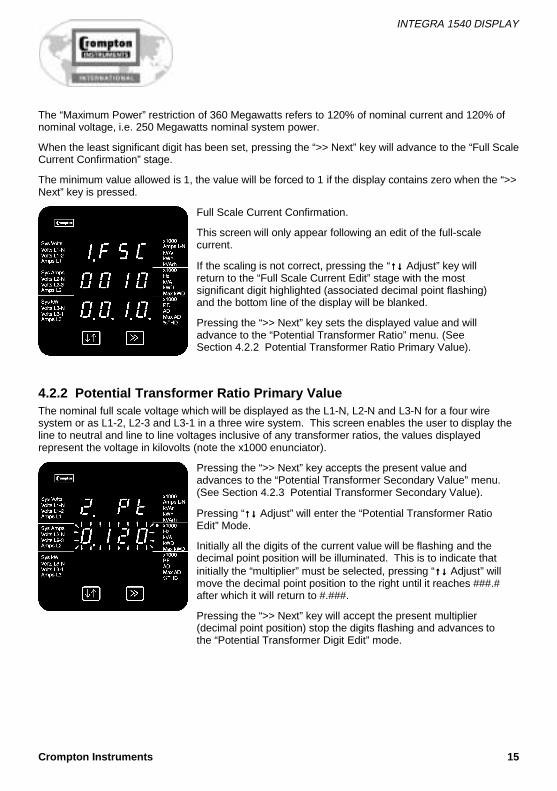
Full Scale Current Confirmation.
This screen will only appear following an edit of the full-scalecurrent.
If the scaling is not correct, pressing the “↑↓↑↓↑↓↑↓ Adjust” key willreturn to the “Full Scale Current Edit” stage with the mostsignificant digit highlighted (associated decimal point flashing)and the bottom line of the display will be blanked.
Pressing the “>> Next” key sets the displayed value and willadvance to the “Potential Transformer Ratio” menu. (SeeSection 4.2.2 Potential Transformer Ratio Primary Value).
4.2.2 Potential Transformer Ratio Primary ValueThe nominal full scale voltage which will be displayed as the L1-N, L2-N and L3-N for a four wiresystem or as L1-2, L2-3 and L3-1 in a three wire system. This screen enables the user to display theline to neutral and line to line voltages inclusive of any transformer ratios, the values displayedrepresent the voltage in kilovolts (note the x1000 enunciator).
Pressing the “>> Next” key accepts the present value andadvances to the “Potential Transformer Secondary Value” menu.(See Section 4.2.3 Potential Transformer Secondary Value).
Pressing “↑↓↑↓↑↓↑↓ Adjust” will enter the “Potential Transformer RatioEdit” Mode.
Initially all the digits of the current value will be flashing and thedecimal point position will be illuminated. This is to indicate thatinitially the “multiplier” must be selected, pressing “↑↓↑↓↑↓↑↓ Adjust” willmove the decimal point position to the right until it reaches ###.#after which it will return to #.###.
Pressing the “>> Next” key will accept the present multiplier(decimal point position) stop the digits flashing and advances tothe “Potential Transformer Digit Edit” mode.

INTEGRA 1540 DISPLAY
16 Crompton Instruments
Potential Transformer Digit Edit.
Pressing “↑↓↑↓↑↓↑↓ Adjust” will scroll the value of the most significantdigit from 0 through to 9 unless the presently displayed potentialtransformer ratio together with the full scale current value,previously set, would result in a maximum power of greater than360 Megawatts in which case the digit range will be restricted.
Pressing the “>> Next” key accepts the present value at thecursor position and advances the cursor to the next lesssignificant digit.(* Denotes that decimal point will be flashing).
Note: the flashing decimal point indicates the cursor position, a steady decimal point will be present toidentify the scaling of the number until the cursor position coincides with the steady decimal pointposition. At this stage the decimal point will flash.
When the least significant digit has been set pressing the “>> Next” key will advance to the “PotentialTransformer Ratio Confirmation” stage.
Screen showing display of 0.120 kV i.e. 120 Volts indicating steady decimal point and cursor flashingat the “hundreds of volts” position.
Potential Transformer Ratio Confirmation.
This screen will only appear following an edit of the PotentialTransformer ratio.
If the scaling is not correct, pressing “↑↓↑↓↑↓↑↓ Adjust” will return to the“Potential Transformer Ratio Edit” stage with the digits flashingindicating that the multiplier (decimal point position) should beselected.
Pressing the “>> Next” key sets the displayed value and willadvance to the “Potential Transformer Secondary Value” menu.(See Section 4.2.3 Potential Transformer Secondary Value).
4.2.3 Potential Transformer Secondary ValueThe nominal full scale secondary voltage which will be displayed as the L1-N, L2-N and L3-N for a fourwire system or as L1-2, L2-3 and L3-1 in a three wire system. This screen enables the user toaccurately define the secondary value which is actually measured to represent the primary value setpreviously. The Integra Transducer (INT-1560 or INT-1580) accepts a wide range of voltage inputsand therefore needs a reference point on the actual input to calculate the correct primary voltagevalue. The secondary voltage shown is in volts.

INTEGRA 1540 DISPLAY
Crompton Instruments 17
Pressing the “>> Next” key accepts the present value andadvances to the “Demand Integration Time” menu. (See Section4.2.4 Demand Integration Time Edit).
Pressing “↑↓↑↓↑↓↑↓ Adjust” will enter the “Potential Transformer Edit”Mode.
Initially all the digits of the current value will be flashing and thedecimal point position will be illuminated. This is to indicate thatinitially the “multiplier” must be selected, pressing “↑↓↑↓↑↓↑↓ Adjust” willmove the decimal point position to the right.
Decimal point edit will only appear for the range 57.7 to 139V.
Pressing “↑↓↑↓↑↓↑↓ Adjust” will move the decimal point to allow voltageless than 100V to be entered, e.g. 57.7V L-N.
Pressing “↑↓↑↓↑↓↑↓ Adjust” again will move the decimal point.
Pressing the “>> Next” key accepts the decimal point positionand moves to the digit edit.
Potential Transformer Digit Edit.
Pressing “↑↓↑↓↑↓↑↓ Adjust” will scroll the value of the most significantdigit of the range indicated on the rating label.
Pressing the “>> Next” key accepts the present value at thecursor position and advances the cursor to the next lesssignificant digit.
Note: the flashing decimal point indicates the cursor position, a steady decimal point will be present toidentify the scaling of the number until the cursor position coincides with the steady decimal pointposition. At this stage the decimal point will flash.
When the least significant digit has been set pressing the “>> Next” key will advance to the “PotentialTransformer Secondary Value Confirmation” stage.
Nominal Input Voltages a.c.(RMS)
Single phase two wireVoltage range 1 57 - 139V L-NVoltage range 2 140 - 277V L-N
Single phase three wireVoltage range 1 57 - 139V L-N (114 - 278V L-L)Voltage range 2 140 - 240V L-N (297 - 480V L-L)
Three phase three wireVoltage range 1 100 - 240V L-LVoltage range 2 241 - 480V L-L

INTEGRA 1540 DISPLAY
18 Crompton Instruments
Three phase four wireVoltage range 1 100 - 240V L-L (57 - 139V L-N)Voltage range 2 241 - 480V L-L (140 - 277V L-N)
Potential Transformer Secondary Value Confirmation
This screen will only appear following an edit of the PotentialTransformer Secondary Value.
If the value is not correct, pressing “↑↓↑↓↑↓↑↓ Adjust” will return to the“Potential Transformer Secondary Value Edit” stage.
Pressing the “>> Next” key sets the displayed value and willadvance to the “Demand Integration Time” menu. (See Section4.2.4 Demand Integration Time Edit ).
4.2.4 Demand Integration Time EditThis screen is used to set the time taken from maximum demand readings; the value displayedrepresents time in minutes.
Pressing the “>> Next” key accepts the present value andadvances to the “Reset” menu. (See Section 4.2.5 Resets).
Pressing the “↑↓↑↓↑↓↑↓ Adjust” key will enter the “Demand IntegrationTime Edit” mode and scroll the value through the valuesavailable.
Pressing the “>> Next” key advances to the “Demand IntegrationTime Confirmation” menu.
As the unit advances to the next screen the unit demands arereset.
Demand Integration Time Confirmation.
This screen will only appear following an edit of the DemandIntegration Time.
If the time shown is not correct, pressing the “↑↓↑↓↑↓↑↓ Adjust” key willreturn to the “Demand Integration Time Edit” stage by blankingthe bottom line of the display.
Pressing the “>> Next” key sets the displayed value and willadvance to the “Reset Selection” menu. (See Section 4.2.5Resets).

INTEGRA 1540 DISPLAY
Crompton Instruments 19
4.2.5 ResetsThe following screens allow the user to reset the Active Energy, Demand and Maximum Demandreadings individually or altogether.
Note: Resetting the Demand will automatically reset the Maximum Demands (HiAd and HiPd).
Reset (None).
Pressing the “>> Next” key advances to the “Pulse Duration”menu. (See Section 4.2.6 Pulsed Output, Pulse Duration).
Pressing the “↑↓↑↓↑↓↑↓ Adjust” key will enter the “Reset ParameterSelect” mode and scroll the “value” through the parametersNone, All, h, and d wrapping back to None.
Pressing the “>> Next” key will not reset any variables and willadvance to the “Pulse Duration Edit” menu. (See Section 4.2.6Pulsed Output, Pulse Duration).
Reset Parameter Select, (Reset All).
The user has scrolled through to the ”ALL” value.
Pressing the “>> Next” key will select the value and advance tothe “Reset All Confirmation” Mode.
Reset All Confirmation.
Pressing the “↑↓↑↓↑↓↑↓ Adjust” key will re-enter the “Reset ParameterSelect” mode.
Pressing the “>> Next” key resets the Energy, Demand andMaximum Demand readings and will advance to the “PulseDuration Edit” mode. (See Section 4.2.6 Pulsed Output, PulseDuration).

INTEGRA 1540 DISPLAY
20 Crompton Instruments
Reset parameter Select, (Reset Energy Variables).
The user has scrolled through to the “h”(Active Energy) value.
Pressing the “>>Next” key will select the value and advance tothe “Reset Active Energy Confirmation” Mode.
Reset Active Energy Variables Confirmation.
Pressing the “↑↓↑↓↑↓↑↓ Adjust” key will re-enter the “Reset ParameterSelect” mode.
Pressing the “>> Next” key resets the Active Energy readingsand will advance to the “Pulse Duration Edit” menu. (SeeSection 4.2.6 Pulsed Output, Pulse Duration).
Reset Parameter Select, (Reset Demands).
The user has scrolled through to the “d” (Demands) value.
Pressing the “>> Next” key will select the value and advance tothe “Reset Demands Confirmation” Mode.
Reset Demands Confirmation.
Pressing the “↑↓↑↓↑↓↑↓ Adjust” key will re-enter the “Reset ParameterSelect” mode.
Pressing the “>> Next” key resets the Demand readings and willadvance to the “Pulse Duration Edit” menu. (See Section 4.2.6Pulsed Output, Pulse Duration).

INTEGRA 1540 DISPLAY
Crompton Instruments 21
4.2.6 Pulsed Output, Pulse DurationThis applies to the Relay Pulsed Output option only.
This screen allows the user to set the duration that the relay pulsed value displayed represents theduration in milliseconds (ms).
Pulse Duration Edit.
Pressing the “>> Next” key accepts the present value andadvances to the “Pulse Rate” menu. (See Section 4.2.7 PulseRate).
Pressing the “↑↓↑↓↑↓↑↓ Adjust” key will enter the “Pulse Duration Edit”mode and scroll the value through the values 60, 100 and 200wrapping back to 60.
Pressing the “>> Next” key selects the value shown andadvances to the “Pulse Duration Confirmation” screen.
Pulse Duration Confirmation.
This screen will only appear following an edit of the pulseduration. In this case the duration has been changed to 100.
If the duration shown is not correct, pressing the “↑↓↑↓↑↓↑↓ Adjust” keywill return to the “Pulse Duration Edit” stage and will blank thebottom line of the display.
Pressing the “>> Next” key sets the displayed value and willadvance to the “Pulse Rate” menu. (See Section 4.2.7 PulseRate).
4.2.7 Pulse RateThis applies to the Relay Pulsed Output option only.
This screen is available for the user to set the kW.h. pulse rate divisor.
Pulse Rate Divisor Edit.
Pressing the “>> Next” key accepts the present value andadvances to the “RS 485 Baud Rate Edit” menu. (SeeSection 4.2.8 RS 485 Baud Rate).
Pressing the “↑↓↑↓↑↓↑↓ Adjust” key will enter the “Pulse Rate DivisorEdit” mode and scroll the value through the values 1, 10, 100,1,000 wrapping back to 1 unless the maximum power is greaterthan 3.6 megawatts in which case the range of divisors will berestricted to force an upper limit to the number of pulses/hour.
Pressing the “>> Next” key advances to the “Pulse Rate DivisorConfirmation” screen.

INTEGRA 1540 DISPLAY
22 Crompton Instruments
Pulse Rate Divisor Confirmation.
This screen will only appear following an edit of the Pulse RateDivisor.
If the divisor shown is not correct, pressing the “↑↓↑↓↑↓↑↓ Adjust” keywill return the operation to the “Pulse Rate Divisor Edit” stage byblanking the bottom line of the display.
Pressing the “>> Next” key sets the displayed value and willadvance to “RS 485 Baud Rate Edit” menu. (See Section 4.2.8RS 485 Baud Rate).
4.2.8 RS 485 Baud RateThis applies to the RS 485 Output option only.
This screen allows the user to set the Baud Rate of the RS 485 Modbus output. The values displayedare in kbaud.
RS 485 Baud Rate Edit.
Pressing the “>> Next” key accepts the present value andadvances to the “RS 485 Parity Selection” menu. (SeeSection 4.2.9 RS 485 Parity Selection).
Pressing the “↑↓↑↓↑↓↑↓ Adjust” key will enter the “RS 485 Baud RateEdit” mode and scroll the value through the values 2.4, 4.8, 9.6and 19.2 wrapping back to 2.4.
Pressing the “>> Next” key advances to the “RS 485 Baud RateConfirmation” menu.
RS 485 Baud Rate Confirmation.
This screen will only appear following an edit of the Baud Rate.
If the rate shown is not correct, pressing the “↑↓↑↓↑↓↑↓ Adjust” key willreturn to the “RS 485 Baud Rate Edit” stage by blanking thebottom line of the display.
Pressing the “>> Next” key sets the displayed value and willadvance operation to “RS 485 Parity Selection” menu. (SeeSection 4.2.9 RS 485 Parity Selection).

INTEGRA 1540 DISPLAY
Crompton Instruments 23
4.2.9 RS 485 Parity SelectionThis applies to the RS 485 Output option only.
This screen allows the user to set the parity of the RS 485 Modbus Output.
RS 485 Parity Selection.
Pressing the “>> Next” key accepts the present value andadvances to the “RS 485 Modbus Address” menu. (SeeSection 4.2.10 RS 485 Modbus Address).
Pressing the “↑↓↑↓↑↓↑↓ Adjust” key will enter the “RS 485 ParitySelection Edit” mode and scroll the value through the valuesodd, E (even), and no 1 (no parity one stop bit), no 2 (no paritytwo stop bits), wrapping back to odd.
Pressing the “>> Next” key advances to the “RS 485 ParityConfirmation” menu.
RS 485 Parity Confirmation.
This screen will only appear following an edit of the ParitySelection.
If the value shown is not correct, pressing the “↑↓↑↓↑↓↑↓ Adjust” key willreturn to the “RS 485 Parity Edit” stage by blanking the bottomline of the display.
Pressing the “>> Next” key sets the value shown and willadvance to the “RS 485 Modbus Address” menu. (See Section4.2.10 RS 485 Modbus Address).
4.2.10 RS 485 Modbus AddressThis applies to the RS 485 Output option only.
This screen allows the user to set the Modbus address, for the instrument, which will be used by theModbus protocol.
RS 485 Modbus Address.
Pressing the “>> Next” key accepts the present value and willreturn to the Display Mode.
Pressing the “↑↓↑↓↑↓↑↓ Adjust” key will enter the “RS 485 ModbusAddress Edit” mode and scroll the value of the most significantdigit from 0 through to 2, the value will wrap from 2 round to 0.(0 to 9 for lesser significant digits). Pressing the “>> Next” keyadvances to the next less significant digit. (* decimal point indicates that this will be flashing).
When the least significant figure has been set, Pressing the“>> Next” key will advance to the “RS 485 Modbus AddressConfirmation” stage.

INTEGRA 1540 DISPLAY
24 Crompton Instruments
Note: When the most significant digit is set to 2 the lesser significant digits must be less than or equalto 47, the digits will scroll through from 0 to 4 and 0 to 7 as appropriate. The range of the allowableaddresses is 1 to 247.
RS 485 Modbus Address Confirmation.
This screen will only appear following an edit of the ModbusAddress.
If the address shown is not correct, pressing the “↑↓↑↓↑↓↑↓ Adjust” keywill return to the “RS 485 Modbus Address Edit” stage with theleast significant digit highlighted (associated decimal pointflashing).
Press the “>> Next” key sets the value shown and will return tothe display mode.
4.2.11 Analogue Output Set UpThis applies to the analogue output option only, allowing theparameter to be selected, and the upper and lower limitsadjusted, for either one or two channels.
Analogue output 1, Output reading edit screen.
The number displayed on the screen represents the parametersshown in the following table.
Pressing the “↑↓↑↓↑↓↑↓ Adjust” key will scroll the value of the mostsignificant digit.
Pressing the “>> Next” key accepts the present value at thecursor position and advances the cursor to the next lesssignificant digit.
Analogue Output Parameters
ParameterNumber Parameter 3 Ø
4 wire3 Ø
3 wire1 Ø
3 wire1 Ø
2 wire +/-
1 Volts 1 (L1 – N 4W or L1 – L2 3W) √ √ √ √ X
2 Volts 2 (L2 – N 4W or L2 – L3 3W) √ √ √ X X
3 Volts 3 (L3 – N 4W or L3 – L1 3W) √ √ X X X
4 Current 1 √ √ √ √ X
5 Current 2 √ √ √ X X
6 Current 3 √ √ X X X
7 Power Phase 1 √ X X X √
8 Power Phase 2 √ X X X √

INTEGRA 1540 DISPLAY
Crompton Instruments 25
ParameterNumber Parameter 3 Ø
4 wire3 Ø
3 wire1 Ø
3 wire1 Ø
2 wire +/-
9 Power Phase 3 √ X X X √
10 VA Phase 1 √ X X X X
11 VA Phase 2 √ X X X X
12 VA Phase 3 √ X X X X
13 VAr Phase 1 √ X X X √
14 VAr Phase 2 √ X X X √
15 VAr Phase 3 √ X X X √
16 Power Factor Phase 1 √ X X X √
17 Power Factor Phase 2 √ X X X √
18 Power Factor Phase 3 √ X X X √
19 Phase Angle Phase 1 √ X X X √
20 Phase Angle Phase 2 √ X X X √
21 Phase Angle Phase 3 √ X X X √
22 Volts Ave √ √ √ √ X
24 Current Ave √ √ √ √ X
25 Current Sum √ √ √ √ X
27 Watts Sum √ √ √ √ √
29 VA Sum √ √ √ √ X
31 VAr Sum √ √ √ √ √
32 Power Factor Ave √ √ √ √ √
34 Average Phase Angle √ √ √ √ √
36 Frequency √ √ √ √ X
37 Wh Import √ √ √ √ X
39 Varh Import √ √ √ √ X
43 W Demand Import √ √ √ √ √
44 W Max. Demand Import √ √ √ √ √
53 A Demand √ √ √ √ X
54 A Max. Demand √ √ √ √ X
101 V L1-L2 (calculated) √ X X X X
102 V L2-L3 (calculated) √ X X X X
103 V L3-L1 (calculated) √ X X X X
104 Average Line to Line Volts √ X X X X

INTEGRA 1540 DISPLAY
26 Crompton Instruments
ParameterNumber Parameter 3 Ø
4 wire3 Ø
3 wire1 Ø
3 wire1 Ø
2 wire +/-
113 Neutral Current √ X √ √ X
118 THD Volts 1 √ √ √ √ X
119 THD Volts 2 √ √ √ X X
120 THD Volts 3 √ √ X X X
121 THD Current 1 √ √ √ √ X
122 THD Current 2 √ √ √ X X
123 THD Current 3 √ √ X X X
125 THD Voltage Mean √ √ √ √ X
126 THD Current Mean √ √ √ √ X
128 Power Factor (+Ind/-Cap) √ √ X X √
Analogue output 1, Output Reading Confirmation screen.
This screen will only appear following an edit of the readingselection. If the reading selected is not correct pressing the“↑↓↑↓↑↓↑↓ Adjust” key will return to the “Output Reading Edit” screen.
Pressing the “>> Next” key sets the displayed parameter addressand moves to the “Reading Top Sign Edit” screen.
Analogue output 1, Reading Top Sign Edit screen.
Pressing the “↑↓↑↓↑↓↑↓ Adjust” key toggles the sign of the parameterbetween positive and negative, the “-“ is shown for negativenumbers, a blank digit is shown for positive numbers. Onlyparameters whose value can be negative will present this option.
Pressing the “>> Next” key accepts the current sign andadvances to the reading top decimal point position.

INTEGRA 1540 DISPLAY
Crompton Instruments 27
Analogue output 1, Reading Top Decimal Point Position Editscreen.
Pressing the “↑↓↑↓↑↓↑↓ Adjust” key will advance the decimal pointposition to the right, illuminating the x1000 annunciator asnecessary and wrapping the decimal point position when thehighest available position for the currently selected reading hasbeen exceeded. (Maximum resolution is 3 digits of the metredvalue.)
Analogue output 1, Reading Top Value Edit screen.
The Integra 1560/1580 limits the adjustment to a maximum of120%, the minimum is zero.
eg. A 230V nominal can be adjusted from 0 to 276V.
Pressing the “↑↓↑↓↑↓↑↓ Adjust” key will scroll the value of the mostsignificant digit to its limit. Pressing the “>> Next” key accepts thecurrent value at the cursor and advances to the next. When all 3digits have been accepted the “Reading Top Confirmation”screen appears.
Analogue output 1, Reading Top Confirmation screen.
If the sign, decimal point or top value is incorrect pressing the“↑↓↑↓↑↓↑↓ Adjust” key will return to the “Analogue Output Reading SignEdit” screen.
Pressing the “>> Next” key accepts the settings For AnalogueOutput 1 Reading Top and advances to “Analogue Output 1Reading Bottom Edit” screen.

INTEGRA 1540 DISPLAY
28 Crompton Instruments
Analogue output 1, Reading Bottom Sign Edit screen.
The “↑↓↑↓↑↓↑↓ Adjust” key toggles the sign of the parameter betweenpositive and negative, the “-“ is shown for negative numbers, ablank digit is shown for positive numbers. Only parameterswhose value can be negative will present this option.
Pressing the “>> Next” key accepts the current sign andadvances to the “Reading Bottom Decimal Point” position.
Analogue output 1, Reading Bottom Decimal Point Position Editscreen.
Pressing the “↑↓↑↓↑↓↑↓ Adjust” key will advance the decimal pointposition to the right, illuminating the x1000 enunciator asnecessary and wrapping the decimal point position when thehighest available position for the currently selected reading hasbeen exceeded.
Analogue output 1, Reading Bottom Value Edit screen.
Integra 1560/1580 limits the adjustment to a maximum of 120%,the minimum is zero.
Pressing the “↑↓↑↓↑↓↑↓ Adjust” key will scroll the value of the mostsignificant digit to its limit. Pressing the “>> Next” key accepts thecurrent value at the cursor and advances to the next. When all 3digits have been accepted the “Reading Bottom Confirmation”screen appears.
INTEGRA 1540 DISPLAY
Crompton Instruments 29
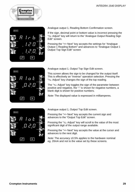
Analogue output 1, Reading Bottom Confirmation screen.
If the sign, decimal point or bottom value is incorrect pressing the“↑↓↑↓↑↓↑↓ Adjust” key will return to the “Analogue Output Reading SignEdit” screen.
Pressing the “>> Next” key accepts the settings for “AnalogueOutput 1 Reading Bottom” and advances to “Analogue Output 1Output Top Sign Edit” screen
Analogue output 1, Output Top Sign Edit screen.
This screen allows the sign to be changed for the output itself.This is effectively an “inverse” operation selection. Pressing the“↑↓↑↓↑↓↑↓ Adjust” key changes the sign of the top reading.
The “↑↓↑↓↑↓↑↓ Adjust” key toggles the sign of the parameter betweenpositive and negative, the “-” is shown for negative numbers, ablank digit is shown for positive numbers.
Note: The displayed value is expressed in milliamperes.
Analogue output 1, Output Top Edit screen.
Pressing the “>> Next” key accepts the current sign andadvances to the “Output Top Edit” screen.
Pressing the “↑↓↑↓↑↓↑↓ Adjust” key will scroll to the value of the mostsignificant digit of the output range available.
Pressing the “>> Next” key accepts the value at the cursor andadvances to the next digit.
Note: The accuracy ±0.5% applies to the hardware nominaleg. 20mA and not to the value set by these screens.

INTEGRA 1540 DISPLAY
30 Crompton Instruments
Analogue output 1, Output Bottom Sign Edit screen.
This screen allows the sign to be changed for the output itself.This is effectively an “inverse” operation selection. Pressing the“↑↓↑↓↑↓↑↓ Adjust” key changes the sign of the bottom reading.
The “↑↓↑↓↑↓↑↓ Adjust” key toggles the sign of the parameter betweenpositive and negative, the “-” is shown for negative numbers, ablank digit is shown for positive numbers.
Analogue output 1, Output Bottom Edit screen.
Pressing the “>> Next” key accepts the current sign andadvances to the “Output Bottom Edit” screen.
Pressing the “↑↓↑↓↑↓↑↓ Adjust” key will scroll to the value of the mostsignificant digit of the output range available.
Pressing the “>> Next” key accepts the value at the cursor andadvances to the next digit.
Analogue output 1, Output Bottom Edit confirmation screen.
If the value is incorrect pressing the “↑↓↑↓↑↓↑↓ Adjust” key will return tothe "Reading Bottom Sign Edit" screen.
Pressing the “>> Next” key accepts the value and advances tothe set up for the second analogue output if fitted.
For the setup of the second analogue output please return to thestart of section 4.2.11.
Please note the display will now display A2r, A2rt, A2rb, A2ot,A2ob.
At the end of the setup for the second analogue output pressing“>> Next” will exit the setup system and enter the display mode.

INTEGRA 1540 DISPLAY
Crompton Instruments 31
5 Specification
InputRS485 Dedicated to Crompton Integra Transducers
AuxiliaryStandard nominal .supply voltages 100 - 250V a.c. or d.c. ±20%a.c. supply frequency range 45 to 66 Hza.c. supply burden 3VA approx.
Optional auxiliary d.c.supply 12 - 48V d.c. -15% + 25%d.c. supply burden 3VA approx.
StandardsTerms, Definitions and Test Methods IEC688:1992 (BSEN 60688) where applicable
EMC Immunity EN61326
10V/m min – Class 1 low level electromagneticradiation environment – EN61000-4-3.
SafetyIEC1010-1 (BSEN 61010-1) Permanently connected use, Normal Condition Installationcategory III, pollution degree 2, Basic Insulation 720V RMS. All terminals are for use onlywith equipment which has no live parts WHICH ARE ACCESSIBLE and the insulation forexternal circuits is to be suitable for SINGLE FAULT CONDITIONS.
InsulationDielectric voltage withstand test 3.25kV RMS 50Hz for 1 minute between all
electrical circuits
EnvironmentalOperating temperature -10 to +70°C
Storage temperature -20 to +80°C
Relative humidity 0 .. 95% non condensing
Shock 30g in 3 planes
Vibration 10-150 Hz, lg/0.15mm amplitude
Enclosure integrity (front face only) IP54
EnclosureStyle ANSI C39.1
Material Polycarbonate front and base, steel case
Terminals Screw clamp style

INTEGRA 1540 DISPLAY
32 Crompton Instruments
Notes

INTEGRA 1540 DISPLAY
Crompton Instruments 33
Notes

Visit our Web Sitewww.crompton.invensys.com
SWITCHBOARD INTEGRA 1540 DISPLAYInstallation and Operating Manual
For more information, please fill in and fax back to your local office
Name: .....................................................................................
Company: .....................................................................................
Address: .....................................................................................
.....................................................................................
.....................................................................................
Tel: .....................................................................................
Fax: .....................................................................................
E-mail: .....................................................................................
Please send me more details on: (please tick) ✓
❐ Generating Set Controllers ❐ Meter Relays
❐ Analogue Indicators ❐ Digital Indicators
❐ Digital Metering Systems ❐ Current Transformers
❐ Transducers ❐ Current Shunts
❐ Protector Relays ❐ Energy Meters
❐ Other Information (please specify)
................................................................................................
Our full Catalogue and Technical Library is available on CDROM
Certificate N° FM21540
Crompton Instruments reserve the right to alter specifications without prior notice. The company makes every effort to ensure contents are correct but cannot accept responsibility for error or omissions.
© Crompton Instruments, November 2001
UNITED KINGDOMHead OfficeCrompton InstrumentsFreebournes Road, WithamEssex. CM8 3AHTel: +44 (0)1376 509509Fax: +44 (0)1376 509511
SalesTel: +44 (0)870 870 7500Fax: +44 (0)1422 248545ExportTel: +44 (0) 1376 509 404Fax: +44 (0) 1376 509 511
BENELUXCrompton Instruments BVTel: +31 180 491199Fax: +31 180 491188
AUSTRALIACrompton Instruments (Aust Pty) Ltd Tel: +61 2 9603 2066Toll Free: 1-300-656-090Fax: +61 2 9603 9335
GERMANYCrompton Messinstrumente GmbHTel: +49 211 5966250Fax: +49 211 5966251
CANADACrompton InstrumentsTel: +1 905 671 2304 / 403 257 3080Fax:+1 905 671 3661 / 403 257 3080
FRANCECrompton InstrumentsTel: +33 3 21 60 81 48Fax: +33 3 21 60 81 49
HONG KONGCrompton Instruments LtdTel: +852 25520267Fax: +852 28731476
SINGAPORECrompton Instruments (SE Asia) Pte LtdTel: +65 481 8866Fax: +65 481 8254
AMERICAS (North & South)Crompton Instruments IncTel: +1 770 425 8903Fax: +1 770 423 7194
CHINACrompton InstrumentsTel: +86 10 6567 8155Fax: +86 10 6567 8154
DIS-1540
Integra 1540 Display 12/7/01 3:05 PM Page 1