installation and operation manual dte-12.pdfsm11 rev. 4.00 dte12/te12/dp12 manual nov 25, 2003 page...
TRANSCRIPT

CONFIDENTIAL AND PROPRIETARY TO NORTHERN AIRBORNE TECHNOLOGY LTD.
SM11 DTE12/TE12/DP12
DTMF Tone Encoder/Data Entry Keypad
INSTALLATION AND OPERATION MANUAL
REV 4.00 November 25, 2003
Northern Airborne Technology Ltd. 1925 Kirschner Road Kelowna BC, Canada
V1Y 4N7
Telephone (250) 763-2232 Facsimile (250) 762-3374
Copyright 2003 by Northern Airborne Technology

SM11 Rev 4.00 DTE12/TE12/DP12 Manual
Nov 25, 2003 Page ii ENG-FORM: 820-0109.DOT
CONFIDENTIAL AND PROPRIETARY TO NORTHERN AIRBORNE TECHNOLOGY LTD.
Periodically NAT will release manual amendments. In order to maintain the most accurate and up to date manual these amendments should be carried out immediately upon receipt and recorded on the following amendment record.
AMENDMENT RECORD
Amendment
Number Amendment
Date Section(s) Changed
Date Entered
Entered By
Insert any Amendment Instruction sheets after this page.


SM11 Rev 4.00 DTE12/TE12/DP12 Manual
Nov 25, 2003 Page iii ENG-FORM: 820-0109.DOT
CONFIDENTIAL AND PROPRIETARY TO NORTHERN AIRBORNE TECHNOLOGY LTD.
Table of Contents Section Title Page 1.0 Description 1.1 Introduction 1-1 1.2 Purpose of Equipment 1-1 1.2.1 DTMF SIgnaling 1-1 1.2.2 Keypad Data Entry 1-1 1.3 Features 1-2 1.4 Specifications 1-3 1.4.1 Electrical Specifications 1-3 1.4.2 Physical Specifications 1-4 1.4.3 Environmental Specifications 1-4 1.5 Unit Nomenclature 1-5 2.0 Installation 2.1 General 2-1 2.2 Unpacking and Inspection 2-1 2.3 Installation Procedures 2-1 2.3.1 Warnings 2-1 2.3.2 Cautions 2-2 2.3.3 Notes 2-2 2.3.4 Cable and Wiring 2-2 2.3.5 External Switches and Breakers 2-3 2.3.6 Post- Installation Checks 2-3 2.4 Installation Configurations 2-4 2.4.1 Tac/Com Systems 2-4 2.4.2 Tac/Com Control Head Serial Ports 2-5 2.4.3 One Data Pad 2-5 2.4.4 One Data Pad and One Slave Control Head 2-6 2.4.5 Two Data Pads and One Slave Control Head 2-9 2.4.6 One Data Pad and Two Slave Control Heads 2-10 2.4.7 Multiple Data Pads and Slave Control Heads 2-14 2.5 Installation Drawings 2-15


SM11 Rev 4.00 DTE12/TE12/DP12 Manual
Nov 25, 2003 Page iv ENG-FORM: 820-0109.DOT
CONFIDENTIAL AND PROPRIETARY TO NORTHERN AIRBORNE TECHNOLOGY LTD.
3.0 Operation 3.1 Introduction 3-1 3.2 Controls 3-1 3.2.1 The Mode Switch (TE12 and DTE12) 3-2 3.2.2 The Function Switch 3-2 3.2.3 Number Buttons (0-9) 3-2 3.2.4 CANCEL, Left Arrow, (*) Button 3-3 3.2.5 ENTER, Right Arrow, (#) Button 3-3 3.2.6 Transmit, Data Error Annunciator 3-3 3.3 DTMF Signaling Operation of TE12/DTE12 3-4 3.3.1 Selecting a Radio 3-4 3.3.2 Manual Transmitting a Tone Sequence 3-4 3.3.3 Retransmitting a Tone Sequence 3-5 3.3.4 Storing a Tone Sequence 3-6 3.3.5 Transmitting a Stored Tone Sequence 3-7 3.3.6 Deleting a Stored Tone Sequence 3-8 3.3.7 Displaying a Stored Tone Sequence 3-9 3.4 Data Entry Mode 3-10 3.4.1 Selecting a Channel on a Control Head 3-10 3.4.2 Editing Frequencies on a Control Head 3-11 3.4.3 DTE12/DP12 Serial Communications Time-out 3-13


SM11 Rev. 4.00 DTE12/TE12/DP12 Manual
Nov 25, 2003 Page 1-1 ENG-FORM: 800-0107.DOT
CONFIDENTIAL AND PROPRIETARY TO NORTHERN AIRBORNE TECHNOLOGY LTD.
Section 1.0 Description
1.1 Introduction
The TE12 and DTE12 are accessory units for use with Tac/Com FM transceivers and other transceivers requiring generation of DTMF (Dual Tone/Multi-Frequency) signaling tones. The DTE12 and DP12 are intended for use with Tac/Com II (TH and UEC series) Control Heads, and provide keypad entry for radio and channel selection, as well as frequency editing.
1.2 Purpose of Equipment
1.2.1 DTMF Signaling
In many systems where air to ground FM communication is carried out, a requirement may exist for special signaling functions such as repeater activation, direct phone patch dialing or selective calling. When this function is to be accomplished using DTMF tones (the same tones heard on a "touch tone" phone), then the TE12 or DTE12 can be used. DTMF tones are momentary tones sent for a specific function, unlike CTCSS or sub-audible tones which are present continuously during transmission to control squelch gate activation. Whenever a tone sequence is selected on the DTE12/TE12, the appropriate transmitter is keyed and the tones are sent to the radio. No other operator intervention is required, and no external transmitter keying is needed. The transceiver immediately returns to the receive mode as soon as the tone sequence has been sent. This function is useful for direct phone dialing (via appropriate radio systems), EMS aircraft to Hospital calling (where DTMF tones are used to activate the specific hospital radio on a common channel), and various repeater control functions. 1.2.2 Keypad Data Entry
The DTE12 and DP12 allow direct channel selection by pressing the channel number buttons and the ENTER button, without having to slew through all the channels between the present and new channel. Transmit or receive frequencies can be edited by simply entering the frequency on the keypad, without having to slew through each digit of the frequency.

DTE12/TE12/DP12 Manual SM11 Rev. 4.00
Page 1-2 Nov 25,2003 ENG-FORM: 800-0107.DOT
CONFIDENTIAL AND PROPRIETARY TO NORTHERN AIRBORNE TECHNOLOGY LTD.
1.3 Features
MICROPROCESSOR CONTROLLED: Unlike many DTMF signaling systems, the TE12 and DTE12 are microprocessor controlled. The tones are digitally stored and synthesized for exceptional long term crystal-controlled stability and accuracy. FLOATING OUTPUTS FOR TWO RADIOS (DTE12/TE12): Two sets of radio connections, floating to minimize noise coupling problems, provide maximum interconnect versatility. The outputs are disconnected from the radios when not active. ADJUSTABLE TONE LEVEL (DTE12/TE12): Individual internal adjustment for each of the two DTMF tone level outputs (0.0-1.0 Vrms into 150 Ω) for level matching with all types of transceivers. TEN MEMORY LOCATIONS (DTE12/TE12): Ten non-volatile memory locations for storing and recalling sequences of up to 11 tones. LAST TONE SEQUENCE RECALL (DTE12/TE12): The last tone sequence entered (up to 11 tones) may be recalled and retransmitted. TRANSMIT ANNUNCIATOR (DTE12/TE12): Front panel LED lights green when the DTE12/TE12 is transmitting a tone sequence. INCOMPLETE OPERATION ANNUNCIATOR (DTE12/TE12): Front panel LED flashes red while an operation is still in progress. TONE SEQUENCE DISPLAY (DTE12): Manually entered, or recalled, tone sequences can be shown on a Tac/Com II (TH and UEC-SERIES) Control Head Display. DATA ENTRY KEYPAD (DTE12/DP12): Provides quick and easy channel selection, and frequency editing, for Tac/Com II (TH and UEC-SERIES) Control Heads.

SM11 Rev. 4.00 DTE12/TE12/DP12 Manual
Nov 25, 2003 Page 1-3 ENG-FORM: 800-0107.DOT
CONFIDENTIAL AND PROPRIETARY TO NORTHERN AIRBORNE TECHNOLOGY LTD.
1.4 Specifications
1.4.1 Electrical Specifications
Input power: +28 VDC (18-32V) Supply Current: 60 mADC idle 110 mADC operating Lighting Current: 160 mADC @ 28 VDC 900 mADC @ 5 VDC Annunciators: (One Bicoloured LED) Transmit Green Incomplete Operation Red (Flashing) Serial Comm. Fault Red (Flashing) Controls: Front Panel Tone/Data Switches (12 Push Buttons) Function Switch (Mom. Centre-off Toggle) Mode Switch (Two or Three Pos'n Toggle) Internal Master Tone Output Level (Potentiometer) Individual Tone Output Levels (2 Potentiometers) Outputs: Transmit Key (2) PTT Key (floating) up to 2 ADC. Tone Output (2) DTMF Audio (floating, can drive 150 ohm mic input up to 1.0 Vrms with or without DC bias). Tones AT&T Telephone standard tones, 697, 770, 852, 941, 1209, 1336, and 1477 (+/- 0.5% max.) Hz. Recalled Tone Sequence Timing PTT start to tone start: 140 ms Tone length: 70 ms Delay between tones: 70 ms

DTE12/TE12/DP12 Manual SM11 Rev. 4.00
Page 1-4 Nov 25,2003 ENG-FORM: 800-0107.DOT
CONFIDENTIAL AND PROPRIETARY TO NORTHERN AIRBORNE TECHNOLOGY LTD.
Tone Assignments "0" 941 Hz + 1336 Hz "1" 697 Hz + 1209 Hz "2" 697 Hz + 1336 Hz "3" 697 Hz + 1477 Hz "4" 770 Hz + 1209 Hz "5" 770 Hz + 1336 Hz "6" 770 Hz + 1477 Hz "7" 852 Hz + 1209 Hz "8" 852 Hz + 1336 Hz "9" 852 Hz + 1477 Hz "*" 941 Hz + 1209 Hz "#" 941 Hz + 1477 Hz Serial Data RS232, 8 bits, 2400 baud, No Handshaking. 1.4.2 Physical Specifications
Weight: 350 g / 0.8 lb. Dimensions: 4.1" deep behind panel. 5.75" wide at front panel, 5.0" behind. 1.125" high. Standard Dzus rack mounting. Allow 2" of connector and cable clearance behind unit (6.1" min. clearance total) 1.4.3 Environmental Specifications
Operating Temperature -40 C to +70 C Storage Temperature -55 C to + 85 C (survival) Altitude 25,000 feet Humidity 95% non-condensing Shock & Vibration 6G, suitable for panel mounting in fixed wing or rotary aircraft.

SM11 Rev. 4.00 DTE12/TE12/DP12 Manual
Nov 25, 2003 Page 1-5 ENG-FORM: 800-0107.DOT
CONFIDENTIAL AND PROPRIETARY TO NORTHERN AIRBORNE TECHNOLOGY LTD.
1.5 Unit Nomenclature
Model Description Panel Lighting DTE12-001 DTMF Tone Encoder / Keyboard Data Entry 28 VDC DTE12-501 DTMF Tone Encoder / Keyboard Data Entry 5 VDC TE12-001 DTMF Tone Encoder 28 VDC TE12-501 DTMF Tone Encoder 5 VDC DP12-001 Keyboard Data Entry 28 VDC DP12-501 Keyboard Data Entry 5 VDC
End of section 1.0


SM11 Rev. 4.00 DTE12/TE12/DP12 Manual
Section 2.0 Installation
2.1 General
Installation information in this section consists of unpacking and inspection procedures, installation procedures, post-installation checks, and installation drawings.
2.2 Unpacking and Inspection
Unpack the equipment carefully, and locate the warranty card. Inspect the unit visually for damage due to shipping, and report all such claims immediately to the carrier involved. Note that each unit supplied should have the following; - DTE12, TE12, or DP12 Unit - Warranty Card - Installation and Operation Manual - Release Certificate Verify that all items are present before proceeding, and report any shortage immediately to your supplier. Complete the warranty card information, and send it to NAT when the installation is complete. If you fail to complete the warranty card, the warranty will be activated on date of shipment from NAT.
2.3 Installation Procedures
2.3.1 Warnings <-- IMPORTANT!
Do not bundle any lines from this unit with transmitter coax lines. Do not bundle any logic, audio, or DC power lines from this unit with 400 Hz synchro wiring or AC power lines. Do not position this unit or wiring from this unit next to any device with a strong alternating magnetic field such as a inverter, or significant audio interference will result.
Nov 25, 2003 Page 2-1 ENG-FORM: 805-0106.DOT
CONFIDENTIAL AND PROPRIETARY TO NORTHERN AIRBORNE TECHNOLOGY LTD.

DTE12/TE12/DP12 Manual SM11 Rev. 4.00 2.3.2 Cautions
In all installations, use shielded cable exactly as shown and ground as indicated. Significant problems may result from not following these guidelines. It is permissible to ground the shield from the DTE12/TE12 audio output at the transceiver, or to a suitable return such as the MIC LO connection to the radio, if this is actually grounded. Do not send the tone data from the DTE12/TE12 as a single conductor shielded wire, as the output of this unit is floating, and provides no shield ground. Be sure both output pins are connected. 2.3.3 Notes
The DTMF output is a low level audio line, and connects to a sensitive point on the transceiver. This line must be shielded, and routed to avoid pick-up to stray fields in the aircraft. Failure to do this will result in noisy transmitter operation when the DTE12/TE12 is in use AND when normal transmissions are made. In essence, the line to the DTE12/TE12 represents an unterminated line attached to the transmitter mic input, and will easily pick up interference if poorly installed and routed. 2.3.4 Cable and Wiring
Use Tefzel M27500 or Raychem spec. 44 (M81044) shielded wire with Raychem D140 series or equivalent solder sleeves (for shield terminations) to make the most compact and easy to terminate interconnect. Follow the wiring diagram provided in Section 2.5 as required for your version. Allow 3" from the end of the wire to the shield termination to allow the hood to be easily installed. Note that the hood is a "clamshell" hood, and is installed after the wiring is complete. All wiring should be at least 24 AWG (22 AWG preferred) except power and ground lines which should be at least 22 AWG (20 AWG preferred). Ensure that the ground connection is clean and well secured.
Page 2-2 Nov 25, 2003 ENG-FORM: 805-0106.DOT
CONFIDENTIAL AND PROPRIETARY TO NORTHERN AIRBORNE TECHNOLOGY LTD.

SM11 Rev. 4.00 DTE12/TE12/DP12 Manual
2.3.5 External Switches and Breakers
There are no additional external components required to make a complete installation with the DTE12/TE12; all functions are self-contained. An individual breaker or fuse should be in the power line of this unit for protection, with a rating no less than 0.5A, and no greater than 1.0A. It is permissible to attach the power feed to the DTE12/TE12 to the breaker of an existing affected radio, if sufficient breaker capacity exists, and wire gauge is adequate for fire protection. 2.3.6 Post-Installation Checks
IMPORTANT! With the DTE12/TE12/DP12 disconnected from its mating connector, check pin <13> for +28 VDC relative to ground, and check pin <25> for continuity to ground (below 0.5 ohms). Check for lighting power on pin <3> (28 VDC), or <6> (14 VDC), or <4> (5 VDC) and a lighting ground on pin <15>. Do not attach the DTE12/TE12/DP12 until these conditions are met, or damage may result to the unit which is not covered under warranty. 2.3.6.1 DTMF Signaling Testing
Turn on the aircraft radios, and set a radio connected to the DTE12/TE12 to a suitable test channel. Set the DTE12/TE12 to the appropriate audio output position (RT1 or RT2), and hold down any tone button, while monitoring the TX output on a suitable communications monitor such as the IFR 1200S. Observe the deviation of the transmitted signal and ensure it does not exceed 3 kHz. If it is over this value, adjust it to no more than 3 kHz with the output level trimpots on the side and top of the DTE12/TE12 (See drawing DTE12\900-0). Set the individual tone level adjustments on the top of the unit to their midway points. Use the master tone level adjustment on the side of the unit for coarse adjustment of the deviation, then the individual tone level adjustments for fine-tuning the deviation levels for the individual transceivers. The optimum setting for use with NAT Tac/Com transceivers is 2 kHz of deviation, which is achieved with a DTE12/TE12 output of 130 mVrms (loaded into the transceiver) or 180 mVrms on an unloaded bench test. Measure this level with an RMS voltmeter only. The exact level desired by any given ground-based system may vary, but is typically between 500 Hz and 3 kHz of deviation on an FM transceiver. If an AM transceiver is used, set the modulation during DTMF transmission to no more than 70%, and no less
Nov 25, 2003 Page 2-3 ENG-FORM: 805-0106.DOT
CONFIDENTIAL AND PROPRIETARY TO NORTHERN AIRBORNE TECHNOLOGY LTD.
DTE12/TE12/DP12 Manual SM11 Rev. 4.00 than 30% with the DTE12/TE12 level adjustments. If two transceivers are used, be sure that operation is satisfactory on both units. Test the store and recall functions for DTMF sequences, and ensure that all functions are fully operational. Refer to section 3.3 for specific operating instructions. 2.3.6.2 Keypad Data Entry Testing
Try the DATA function on the DTE12/DP12, and ensure that you can select channels and perform frequency editing as described in section 3.4 of this manual. If all functions are satisfactory, including panel lighting, tone output, data entry (if used) and store/recall, and if no interference problems are found in a system check of the aircraft radios, then the aircraft may be returned to service, and the appropriate log entries and approval documentation filed.
2.4 Installation Configurations
2.4.1 Tac/Com Systems
A Tac/Com system is defined as one master Tac/Com control head and all the radios and peripheral devices connected to it. All the peripherals communicate with the master control head through serial ports. When DTE12/DP12 units are installed in Tac/Com systems, there are several different configurations possible. The configuration that is selected will depend on whether there is room in the master control head for a serial I/O expansion board, and with which control head(s) the data pad(s) will be used. It is important to know with which control head a DTE12 will be used because the DTE12 tone sequences will be displayed only on that control head, not the others in the system. A DTE12/DP12, when used to edit frequency data, must be used with a master control head. Note for the rest of this section, DTE12/DP12 units will simply be referred to as Data Pads.
Page 2-4 Nov 25, 2003 ENG-FORM: 805-0106.DOT
CONFIDENTIAL AND PROPRIETARY TO NORTHERN AIRBORNE TECHNOLOGY LTD.

SM11 Rev. 4.00 DTE12/TE12/DP12 Manual
2.4.2 Tac/Com Control Head Serial Ports
The main serial port (referred to as Port A) on both master and slave control heads is located on the system connector (J100). Additional serial ports may be added to both master and slave control heads. These are located on an optional serial I/O expansion board (interface 'Y'), and are referred to as Ports B and C. All control head serial ports are RS-232 compatible, and can be used to communicate with a data pad. The master control head must have its data pad port configured properly before the system will function. Configuration is accomplished via the front panel controls and must be performed by a qualified technician. For details, see the Installation and Configuration Mode section of the Tac/Com Control Head manual. When a slave control head is connected to a master, it is always done so by connecting port A of the slave to port A of the master. When additional slaves are added to a system, they are 'daisy chained' from the first slave. Port A of each additional slave must be connected to port C of the previous slave. Port B of each slave is reserved for connecting to other peripherals such as data pads. 2.4.3 One Data Pad
For the simplest system, where a single data pad is connected to a single control head, there is only one possible configuration. The data pad is connected to Port A of the control head, and no serial I/O expansion board is necessary. Configure the control head data pad port to 'A'.
Dwg: DTE12\302-1101
Nov 25, 2003 Page 2-5 ENG-FORM: 805-0106.DOT
CONFIDENTIAL AND PROPRIETARY TO NORTHERN AIRBORNE TECHNOLOGY LTD.

DTE12/TE12/DP12 Manual SM11 Rev. 4.00 2.4.4 One Data Pad and One Slave Control Head
For this system there are three possible configurations. 2.4.4.1 One Data Pad and One Slave - Configuration #1
When the data pad is to be used with the master control head, and there is room in the master for a serial I/O expansion board, install the board in the master and connect the data pad to port B of the master. Connect port A of the slave to port A of the master. Configure the master control head data pad port to 'B'.
Dwg: DTE12\302-2101
Page 2-6 Nov 25, 2003 ENG-FORM: 805-0106.DOT
CONFIDENTIAL AND PROPRIETARY TO NORTHERN AIRBORNE TECHNOLOGY LTD.

SM11 Rev. 4.00 DTE12/TE12/DP12 Manual
2.4.4.2 One Data Pad and One Slave - Configuration #2
When the data pad is to be used with the master control head, but there isn't room in the master for a serial I/O expansion board, install the board in the slave and connect the data pad to port B of the slave. Connect port A of the slave to port A of the master. Configure the master control head data pad port to 'A'.
Dwg: DTE12\302-3101
Nov 25, 2003 Page 2-7 ENG-FORM: 805-0106.DOT
CONFIDENTIAL AND PROPRIETARY TO NORTHERN AIRBORNE TECHNOLOGY LTD.
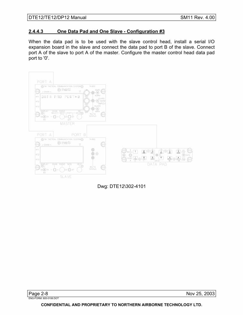
DTE12/TE12/DP12 Manual SM11 Rev. 4.00 2.4.4.3 One Data Pad and One Slave - Configuration #3
When the data pad is to be used with the slave control head, install a serial I/O expansion board in the slave and connect the data pad to port B of the slave. Connect port A of the slave to port A of the master. Configure the master control head data pad port to '0'.
Dwg: DTE12\302-4101
Page 2-8 Nov 25, 2003 ENG-FORM: 805-0106.DOT
CONFIDENTIAL AND PROPRIETARY TO NORTHERN AIRBORNE TECHNOLOGY LTD.

SM11 Rev. 4.00 DTE12/TE12/DP12 Manual
2.4.5 Two Data Pads and One Slave Control Head
For this system there is only one possible configuration. Install I/O expansion boards in both control heads, connect the master data pad to port B of the master control head, and connect the slave data pad to port B of the slave control head. Connect port A of the slave to port A of the master. Configure the master control head data pad port to 'B'.
Dwg: DTE12\302-5101
Nov 25, 2003 Page 2-9 ENG-FORM: 805-0106.DOT
CONFIDENTIAL AND PROPRIETARY TO NORTHERN AIRBORNE TECHNOLOGY LTD.

DTE12/TE12/DP12 Manual SM11 Rev. 4.00 2.4.6 One Data Pad and Two Slave Control Heads
For this system there are four possible configurations. 2.4.6.1 One Data Pad and Two Slaves - Configuration #1
When the data pad is to be used with the master control head, and there is room in the master for a serial I/O expansion board, install the board in the master and connect the data pad to port B of the master. Also install an I/O expansion board in the first slave control head. Connect port A of the first slave to port A of the master. Connect port A of the second slave to port C of the first slave. Configure the master control head data pad port to 'B'.
Dwg: DTE12\302-6101
Page 2-10 Nov 25, 2003 ENG-FORM: 805-0106.DOT
CONFIDENTIAL AND PROPRIETARY TO NORTHERN AIRBORNE TECHNOLOGY LTD.

SM11 Rev. 4.00 DTE12/TE12/DP12 Manual
2.4.6.2 One Data Pad and Two Slaves - Configuration #2
When the data pad is to be used with the master control head, but there isn't room in the master for a serial I/O expansion board, install the board in the first slave and connect the data pad to port B of that slave. Connect port A of the first slave to port A of the master. Connect port A of the second slave to port C of the first slave. Configure the master control head data pad port to 'A'.
Dwg: DTE12\302-7101
Nov 25, 2003 Page 2-11 ENG-FORM: 805-0106.DOT
CONFIDENTIAL AND PROPRIETARY TO NORTHERN AIRBORNE TECHNOLOGY LTD.
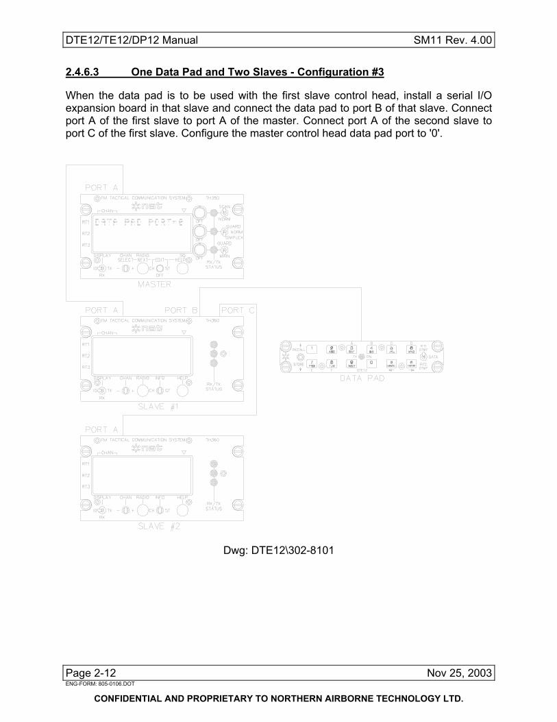
DTE12/TE12/DP12 Manual SM11 Rev. 4.00 2.4.6.3 One Data Pad and Two Slaves - Configuration #3
When the data pad is to be used with the first slave control head, install a serial I/O expansion board in that slave and connect the data pad to port B of that slave. Connect port A of the first slave to port A of the master. Connect port A of the second slave to port C of the first slave. Configure the master control head data pad port to '0'.
Dwg: DTE12\302-8101
Page 2-12 Nov 25, 2003 ENG-FORM: 805-0106.DOT
CONFIDENTIAL AND PROPRIETARY TO NORTHERN AIRBORNE TECHNOLOGY LTD.

SM11 Rev. 4.00 DTE12/TE12/DP12 Manual
2.4.6.4 One Data Pad and Two Slaves - Configuration #4
When the data pad is to be used with the second slave control head, install serial I/O expansion boards in both slaves. Connect the data pad to port B of the second slave. Connect port A of the first slave to port A of the master. Connect port A of the second slave to port C of the first slave. Configure the master control head data pad port to '0'.
Dwg: DTE12\302-9101
Nov 25, 2003 Page 2-13 ENG-FORM: 805-0106.DOT
CONFIDENTIAL AND PROPRIETARY TO NORTHERN AIRBORNE TECHNOLOGY LTD.
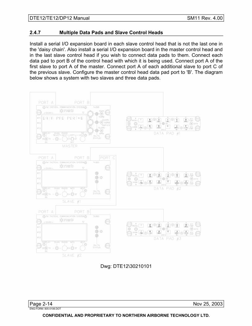
DTE12/TE12/DP12 Manual SM11 Rev. 4.00 2.4.7 Multiple Data Pads and Slave Control Heads
Install a serial I/O expansion board in each slave control head that is not the last one in the 'daisy chain'. Also install a serial I/O expansion board in the master control head and in the last slave control head if you wish to connect data pads to them. Connect each data pad to port B of the control head with which it is being used. Connect port A of the first slave to port A of the master. Connect port A of each additional slave to port C of the previous slave. Configure the master control head data pad port to 'B'. The diagram below shows a system with two slaves and three data pads.
Dwg: DTE12\30210101
Page 2-14 Nov 25, 2003 ENG-FORM: 805-0106.DOT
CONFIDENTIAL AND PROPRIETARY TO NORTHERN AIRBORNE TECHNOLOGY LTD.

SM11 Rev. 4.00 DTE12/TE12/DP12 Manual
2.5 Installation Drawings
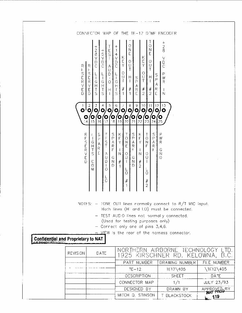
DRAWING REV. DESCRIPTION TYPE DTE12\905-0 2.00 DTE12 Faceplate Mechanical TE12\905-0 2.00 TE12 Faceplate Mechanical DP12\905-0 2.00 DP12 Faceplate Mechanical DTE12\900-0 1.10 DTE12 Orthographic Drawing Mechanical DTE12\403 C DTE12 Interconnect Interconnect TE12\403 A TE12 Interconnect Interconnect DP12\403 - DP12 Interconnect Interconnect DTE12\405 A DTE12 Connector Map Connector Map TE12\405 - TE12 Connector Map Connector Map DP12\405 - DP12 Connector Map Connector Map Earlier Revision Diagrams DTE12\905A A DTE12 Faceplate - Serial Number 1001 to 1143Mechanical TE12\905A A TE12 Faceplate - Serial Number 1001 to 1143Mechanical DP12\905 - DP12 Faceplate - Serial Number 1001 to 1143Mechanical DTE12\900 - DTE12 Orthographic Drawing Ser. Nos. 1001 to 1143 Mechanical
Section 2.0 ends following these drawings.
Nov 25, 2003 Page 2-15 ENG-FORM: 805-0106.DOT
CONFIDENTIAL AND PROPRIETARY TO NORTHERN AIRBORNE TECHNOLOGY LTD.


SM11 Rev. 4.00 DTE12/TE12/DP12 Manual
Section 3.0 Operation
3.1 Introduction
There are two modes of operation for this product family, DTMF SIGNALING, and KEYPAD DATA ENTRY. The TE12 and DTE12 have DTMF tone generation capability, the DTE12 and DP12 have Keypad Data Entry functions, and the DTE12 is able to display DTMF tone sequence numbers on a Tac/Com II Control Head display. The information contained in this section applies to both earlier and current generation units
3.2 Controls
TE12 Controls Function switch Annunciator Mode switch
Tone buttons
DTE12 Controls Function switch Annunciator Mode switch
Keypad/Tone buttons
Nov 25, 2003 Page 3-1 ENG-FORM: 806-0106.DOT
CONFIDENTIAL AND PROPRIETARY TO NORTHERN AIRBORNE TECHNOLOGY LTD.

DTE12/TE12/DP12 Manual SM11 Rev. 4.00 DP12 Controls Function switch Fault Annunciator
Keypad buttons
3.2.1 The Mode Switch (TE12 and DTE12) On the TE12 the Mode switch is a two-position toggle switch that selects DTMF Operation on either RT1 or RT2. On the DTE12 the Mode switch is a three-position toggle switch that selects between Data Entry Mode and DTMF mode on RT1 or RT2. The DP12 does not have a Mode switch and is always in Data Entry Mode.
3.2.2 The Function Switch The Function switch is a three-position, momentary, centre-off, toggle switch. While in DTMF Mode (TE12 and DTE12 only) the Function switch allows tone sequences to be stored and recalled from the ten memory locations. While in Data Entry Mode (DTE12 and DP12 only) and during Normal Control Head operation the Function switch provides a way to select the next or previous radio. During Control Head Channel Edit, the Function switch provides a way to select the next or previous channel to edit.
3.2.3 Number buttons (0-9) While in DTMF Mode (TE12 and DTE12 only) the Number buttons allow the selected transceiver to be keyed and the associated tone to be generated. During DTMF Recall and Store functions, the Number buttons are used to select one of the ten memory locations. While in Data Entry Mode (DTE12 and DP12 only) the Number buttons are used to select channels and receive and transmit frequencies. The Number buttons 3, 4, 5, 6, 7, 8 can be used to select channels by bank. The bank letter (A, B, C, D, E, F) is engraved above the Number button.
Page 3-2 Nov 25, 2003 ENG-FORM: 806-0106.DOT
CONFIDENTIAL AND PROPRIETARY TO NORTHERN AIRBORNE TECHNOLOGY LTD.
SM11 Rev. 4.00 DTE12/TE12/DP12 Manual 3.2.4 CANCEL , Left Arrow , (*) Button While in DTMF Mode (TE12 and DTE12 only) this is the (*) button, and is used to key the selected transceiver and generate the associated tone. During the DTMF Recall function this is the CANCEL button, and is used to exit the Recall function. During the DTMF Store function this is the CANCEL button, and is used to clear the data stored in the selected memory location. While in Data Entry Mode (DTE12 and DP12 only) during channel edit, this is the Left Arrow ( ) button and is used to select the previous field or digit for editing. During Normal control head operation it is the CANCEL button and is used to cancel the channel change command.
3.2.5 ENTER , Right Arrow, (#) Button While in DTMF Mode (TE12 and DTE12 only) this is the (#) button and is used to key the selected transceiver and generate the associated tone. During the DTMF Recall function this is the ENTER button, and is used to initiate transmission of a tone sequence. During the DTMF Store function this is the ENTER button, and is used to initiate the storage of a tone sequence in a memory location. While in Data Entry Mode (DTE12 and DP12 only) and during control head channel edit, this is the Right Arrow ( ) button and is used to select the next field or digit for editing. During Normal control head operation it is the ENTER button and is used to complete the channel change command.
3.2.6 Transmit, Data Error Annunciator This is a bicoloured light emitting diode. While in DTMF mode (TE12 and DTE12 only) the annunciator lights GREEN when the selected transceiver is transmitting. During the DTMF Recall and Store functions the annunciator will FLASH RED to indicate that an operation is incomplete. The operator must select a memory location, and press the CANCEL or ENTER button. In Data Entry Mode (DTE12 and DP12 only) the annunciator will FLASH RED if there is an error in the transfer of serial data between the DTE12/DP12 and the Control Head.
Nov 25, 2003 Page 3-3 ENG-FORM: 806-0106.DOT
CONFIDENTIAL AND PROPRIETARY TO NORTHERN AIRBORNE TECHNOLOGY LTD.

DTE12/TE12/DP12 Manual SM11 Rev. 4.00 3.3 DTMF Signaling Operation of the TE12 and DTE12
3.3.1 Selecting a Radio 1) Ensure the radio is on and correctly channeled before transmitting. 2) Use the Mode switch to select the transceiver that will transmit the DTMF tone sequence. The TE12 and DTE12 support two transceivers.
Tone Transmission on RT1
Tone Transmission on RT2
3.3.2 Manually Transmitting a Tone Sequence To manually transmit a tone or tone sequence: 1) Select the radio you want to transmit on with the Mode switch (RT1/RT2). 2) Press the Keypad buttons (0-9,*,#) that correspond to the tone sequence you want to transmit.
The DTE12/TE12 will key the selected transceiver and generate a tone for each button that you press. One button press will result in one tone, no matter how long the button is depressed. On DTE12 units that are connected to a Tac/Com II Control Head, the number of the first eleven buttons pressed will be shown on the display of the control head. The DTE12/TE12 unit will wait approximately two seconds for the next Keypad button to be pressed. After two seconds, the DTE12/TE12 unit will release the transmit key, and the control head display will revert to normal.
Page 3-4 Nov 25, 2003 ENG-FORM: 806-0106.DOT
CONFIDENTIAL AND PROPRIETARY TO NORTHERN AIRBORNE TECHNOLOGY LTD.

SM11 Rev. 4.00 DTE12/TE12/DP12 Manual
The first eleven tones of this tone sequence are now stored in the Last Number memory location and may be transmitted again using the Retransmit Function, or may be stored in a permanent memory location.
3.3.3 Retransmitting a Tone Sequence To retransmit the last manually entered tone sequence: 1) Select the radio you want to transmit on, with the Mode switch (RT1/RT2). 2) Toggle the Function switch to RECALL. The annunciator will FLASH RED. 3) Press the ENTER button.
The annunciator will light GREEN. The selected transceiver will be keyed and the last manually entered tone sequence will be transmitted. On DTE12 units the tone sequence will be shown on the control head display.
2 1
3
Nov 25, 2003 Page 3-5 ENG-FORM: 806-0106.DOT
CONFIDENTIAL AND PROPRIETARY TO NORTHERN AIRBORNE TECHNOLOGY LTD.

DTE12/TE12/DP12 Manual SM11 Rev. 4.00 3.3.4 Storing a Tone Sequence The memory inside the DTE12/TE12 can hold up to 10 separate 11-digit tone sequences. These are stored in locations accessed through the Number buttons (0-9) . The DTE12/TE12 uses non-volatile memory to store the tone data, and there is no battery or ship power connection required to retain the information. To store a tone sequence: 1) Select the radio you want to transmit on with the Mode switch (RT1/RT2). 2) Enter in the tone sequence using the Keypad buttons (0-9, *, #). This will key the radio and transmit the tone sequence. The annunciator will light green. 3) Wait until the radio has stopped transmitting and the annunciator has
turned off. The Control Head will lock-up if you press the STORE switch while the
radio is transmitting. 4) Momentarily toggle the Function switch to STORE. The annunciator will FLASH RED. 5) Press the Number button of the desired storage location, 0-9. The annunciator will still FLASH RED.
If the wrong Number button was pressed, then press the correct Number button.
6) Press the ENTER button.
The DTE12/TE12 will then store the tone sequence in the location you have selected (0-9), and the annunciator will turn off.
4 3 1
6 Note: If the last tone sequence entered is greater than 11 tones, only the first 11 tones
will be stored.
Page 3-6 Nov 25, 2003 ENG-FORM: 806-0106.DOT
CONFIDENTIAL AND PROPRIETARY TO NORTHERN AIRBORNE TECHNOLOGY LTD.

SM11 Rev. 4.00 DTE12/TE12/DP12 Manual 3.3.5 Transmitting a Stored Tone Sequence To transmit a stored tone sequence: 1) Select the radio you want to transmit on with the Mode switch (RT1/RT2). 2) Momentarily toggle the Function switch to RECALL. The annunciator will FLASH RED. 3) Press the Number button (0-9) of the location of the stored tone sequence.
If a DTE12 is being used, the stored tone sequence will be shown on the display of the control head. The annunciator will still FLASH RED. If the wrong Number button was pressed, then press the correct Number button.
4) Press the ENTER button.
The annunciator will light GREEN, the selected radio will be keyed and the tone sequence will be transmitted.
To exit this mode without transmitting the tone sequence, press the CANCEL button instead of the ENTER button. 2 1
4
Nov 25, 2003 Page 3-7 ENG-FORM: 806-0106.DOT
CONFIDENTIAL AND PROPRIETARY TO NORTHERN AIRBORNE TECHNOLOGY LTD.

DTE12/TE12/DP12 Manual SM11 Rev. 4.00 3.3.6 Deleting a Stored Tone Sequence A stored tone sequence may be removed from the DTE12/TE12, without having to store another tone sequence in that location. To delete a stored tone sequence: 1) Select the DTMF mode with the Mode switch (RT1/RT2). 2) Momentarily toggle the Function switch to STORE. The annunciator will FLASH RED.
3) Press the Number (0-9) button of the memory location from which tone sequence is to be deleted.
The annunciator will FLASH RED. 4) Press the CANCEL button. This will erase the tone sequence and leave the memory location blank. 2 1
4
Page 3-8 Nov 25, 2003 ENG-FORM: 806-0106.DOT
CONFIDENTIAL AND PROPRIETARY TO NORTHERN AIRBORNE TECHNOLOGY LTD.

SM11 Rev. 4.00 DTE12/TE12/DP12 Manual 3.3.7 Displaying Stored Tone Sequences (DTE12 only) To display the tone sequence of a memory location: 1) Select the DTMF mode with the Mode switch (RT1/RT2). 2) Momentarily toggle the Function switch to RECALL. The annunciator will FLASH RED. 3) Press the Number (0-9) button of the location of the stored tone sequence. The annunciator will FLASH RED.
The tone sequence will be show on the control head display. Continue to press the Number (0-9) buttons to view the tone sequences of the other memory locations.
4) Press the CANCEL button. To transmit the tone sequence on the selected transceiver press the ENTER button instead of the CANCEL button. 2 1
4
Nov 25, 2003 Page 3-9 ENG-FORM: 806-0106.DOT
CONFIDENTIAL AND PROPRIETARY TO NORTHERN AIRBORNE TECHNOLOGY LTD.

DTE12/TE12/DP12 Manual SM11 Rev. 4.00 3.4 Data Entry Mode (DTE12 and DP12 Units)
The DTE12/DP12 units connect with Tac/Com II Control Heads to serve as data entry keypad units. Using the DTE12/DP12 keypad, control head channeling and frequency editing can be more easily accomplished.
3.4.1 Selecting a Channel on a Control Head With the DTE12/DP12, it is possible to channel the Tac/Com control head. To select a new channel on the Tac/Com II Control Head: 1) Ensure the Tac/Com II Control Head Edit switch is in the Off position. 2) Put the Mode switch in the Data position (DTE12 Only). 3) Use the Function ( ↑ ↓ ) switch to move the cursor to the control head display line of the transceiver that is to be channeled. (The Control Head 'Radio/Next' button may also be used.) 4) Press the Number buttons of the channel you want to select. Use the same method of channel numbering as is displayed on the control head. Sequential channel numbers range from the lowest to the highest channel number in the control head display. Banked channel numbers use A, B, C, D, E, F (the buttons 3, 4, 5, 6, 7, 8) followed by the lowest to the highest channel number in the bank. 5) Press the ENTER button. To exit the select channel command press the CANCEL button instead of the ENTER button. Example: To select channel 128, press: '1', '2', '8', 'ENTER'. To select channel 001, press: '1', or '0', '1', or '0','0','1', 'ENTER'. To select channel B12, press: 'B'('4'), '1', '2', 'ENTER'.
Page 3-10 Nov 25, 2003 ENG-FORM: 806-0106.DOT
CONFIDENTIAL AND PROPRIETARY TO NORTHERN AIRBORNE TECHNOLOGY LTD.

SM11 Rev. 4.00 DTE12/TE12/DP12 Manual 3 2
5
DATA ENTRY MODE-CHANNEL SELECTION
Note: Only the last three channel numbers pressed before the ENTER button is pressed will be used for channel selection. If an invalid channel number is entered, no channel change will occur and the control head will display the message "CHANNEL ERROR".
3.4.2 Editing Frequencies on a Control Head The DTE12/DP12 may be used to enter receive and transmit frequencies while the Tac/Com Control Head is in Channel Edit Mode. To edit a frequency: 1) Select the channel to be edited on the Control Head. Use the DTE12/DP12 channel selection (See 3.2.2), or the Control Head CHAN/SELECT and RADIO/NEXT switches. 2) Put the Control Head EDIT switch in the CH (Channel) position. The first editable digit in the control head display will be flashing. 3) Put the Control Head DISPLAY switch in the TX position. 4) Enter the new transmit frequency on the DTE12/DP12 keypad. Use the Number buttons to enter the frequency digits. Use the ( ) button to edit the previous digit. Use the ( ) button to edit the next digit. The decimal point and the receive/transmit/simplex flag will be
skipped during editing. 5) Use the Control Head CHAN/SELECT switch to select the transmit tone. 6) Put the Control Head DISPLAY switch to the RX position.
Nov 25, 2003 Page 3-11 ENG-FORM: 806-0106.DOT
CONFIDENTIAL AND PROPRIETARY TO NORTHERN AIRBORNE TECHNOLOGY LTD.

DTE12/TE12/DP12 Manual SM11 Rev. 4.00 7) Enter the new receive frequency and tone on the DTE12/DP12 keypad as per
steps 4 and 5. 8) Toggle the Function ( ↑ ↓ ) switch to select the next channel for editing. 9) When finished editing put the Control Head EDIT switch in the OFF position.
DATA ENTRY MODE-FREQUENCY
Example: To enter the transmit frequency 151.475 MHz, Put the Control Head Edit switch to the CH position. Put the Control Head Display switch in the TX position. Press the following DTE12/DP12 Number buttons: 1, 5, 1, 4, 7, 5 Put the Control Head Edit switch to the OFF position. 3.4.2.1 Notes: If an out of band frequency is entered, the Control Head will display asterisks instead of the receive or transmit frequency when the Edit switch is returned to the OFF position. Example: >001 ∗∗∗.∗∗∗t - Go back into Channel edit mode and enter a valid frequency. Editing a frequency to all zeros can be used to completely erase a channel (create a 'blank' channel). When the ( ) or ( ) buttons are used to move the editable (flashing) character past the end of the display line, it will 'wrap-around' to the other end of the display line. 3.4.2.2 Limitations of Frequency Edit: The DTE12/DP12 unit will not allow editing of the Alpha-numeric label that is displayed in the Control Head's ID - Display. The DTE12/DP12 unit will not allow editing of the receive or transmit tones. The Alpha-numeric label and receive and transmit tones must be edited from the Control Head by using the SELECT '+ / -' toggle switch. However, you may use the ( ) and ( ) buttons on the DTE12/DP12 to move to the previous, or next, portion of the receive or transmit tone.
Page 3-12 Nov 25, 2003 ENG-FORM: 806-0106.DOT
CONFIDENTIAL AND PROPRIETARY TO NORTHERN AIRBORNE TECHNOLOGY LTD.
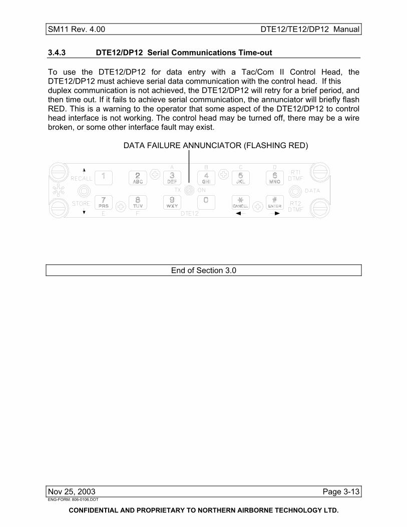
SM11 Rev. 4.00 DTE12/TE12/DP12 Manual 3.4.3 DTE12/DP12 Serial Communications Time-out To use the DTE12/DP12 for data entry with a Tac/Com II Control Head, the DTE12/DP12 must achieve serial data communication with the control head. If this duplex communication is not achieved, the DTE12/DP12 will retry for a brief period, and then time out. If it fails to achieve serial communication, the annunciator will briefly flash RED. This is a warning to the operator that some aspect of the DTE12/DP12 to control head interface is not working. The control head may be turned off, there may be a wire broken, or some other interface fault may exist.
DATA FAILURE ANNUNCIATOR (FLASHING RED)
End of Section 3.0
Nov 25, 2003 Page 3-13 ENG-FORM: 806-0106.DOT
CONFIDENTIAL AND PROPRIETARY TO NORTHERN AIRBORNE TECHNOLOGY LTD.
