installation and operation - hearthnhome.com filenotice installation and service of this appliance...
TRANSCRIPT

Heat & Glo • 8000TV-OAK, 8000TV-OAK-IPI, 8000TVLP-OAKIPI • 2058-900 Rev. O • 6/09 1
• DO NOT store or use gasoline or other fl am-mable vapors and liquids in the vicinity of this or any other appliance.
• What to do if you smell gas - DO NOT try to light any appliance.- DO NOT touch any electrical switch. DO
NOT use any phone in your building.- Immediately call your gas supplier from a
neighbor’s phone. Follow the gas suppli-er’s instructions.
- If you cannot reach your gas supplier, call the fi re department.
• Installation and service must be performed by a qualifi ed installer, service agency, or the gas supplier.
WARNING: If the information in these instructions is not followed exactly, a fi re or explosion may result causing property damage, personal injury, or death.
Owner’s ManualInstallation and Operation
DO NOT DISCARD THIS MANUAL
NOTICE
Installation and service of this appliance should be performed by qualifi ed personnel. Hearth & Home Technologies suggests NFI certifi ed or factory trainedprofessionals, or technicians supervised by an NFI certifi ed professional.
• Leave this manual with party responsible for use and operation.
DO NOTDISCARD
WARNING
• Important operating and maintenance instructions included.
• Read, understand and follow these instructions for safe installation and operation.
In the Commonwealth of Massachusetts installation must be performed by a licensed plumber or gas fi tter.A CO detector shall be installed in the room where the appliance in installed.
This appliance has been supplied with an integral barrier to prevent direct contact with the fi xed glass panel. DO NOT operate the appliance with the barrier removed. Contact your dealer or Hearth & Home Technologies if the barrier is not present or help is needed to properly install one.
HOT SURFACES!Glass and other surfaces are hot during operation AND cool down.
Hot glass will cause burns.• DO NOT touch glass until it is cooled• NEVER allow children to touch glass• Keep children away
• CAREFULLY SUPERVISE children in same room as fi replace.
• Alert children and adults to hazards of high temperatures.
High temperatures may ignite clothing or other fl ammable materials.• Keep clothing, furniture, draperies and other fl ammable
materials away.
Models:8000TV-OAK8000TV-OAK-IPI8000TVLP-OAKIPI
Para obtener un ejemplar en Español de esteManual del propietario, visite www.heatnglo.com.
Pour demander un exemplaire en français de ce Manuel du propriétaire, visitez www.heatnglo.com.

Heat & Glo • 8000TV-OAK, 8000TV-OAK-IPI, 8000TVLP-OAKIPI • 2058-900 Rev. O • 6/092
Listing Label Information/Location
Model Name: ___________________________________________ Date purchased/installed: __________________
Serial Number: __________________________________________ Location on fi replace: _____________________
Dealership purchased from: _______________________________ Dealer Phone: __________________________
Notes: _______________________________________________________________________________________
_____________________________________________________________________________________________
A. CongratulationsCongratulations on selecting a Heat & Glo gas fi replace, an elegant and clean alternative to wood burning fi replaces. The Heat & Glo gas fi replace you have selected is designed to provide the utmost in safety, reliability, and effi ciency.As the owner of a new fi replace, you’ll want to read and carefully follow all of the instructions contained in this owner’s manual. Pay special attention to all cautions and warnings.
This owner’s manual should be retained for future reference. We suggest that you keep it with your other important documents and product manuals.The information contained in this owner’s manual, unless noted otherwise, applies to all models and gas control systems.Your new Heat & Glo gas fi replace will give you years of durable use and trouble-free enjoyment. Welcome to the Heat & Glo family of fi replace products!
We recommend that you record the following pertinent information about your fi replace.
Gas and Electric Information
Serial Number
Type of Gas
The model information regarding your specifi c fi replace can be found on the rating plate usually located in the control area of the fi replace.
Homeowner Reference Information
Model Number
Read this manual before installing or operating this appliance. Please retain this owner’s manual for future reference.
NotNot for for use use withwith solid solid fuel.fuel.((NeNe doitdoit pas pas entre entre utilise utilise avecavec un un combustible combustible solide).solide).
ThisThis appliance appliance mustmust bebe installed installed inin accordanceaccordance withwith local local codes,codes, ifif any;any; ifif not,not, follow follow ANSIANSI Z223.1Z223.1inin the the USA USA oror CAN/CGA CAN/CGA B149 B149 installation installation codes.codes. (Installer(Installer l’appareill’appareil selon selon lesles codes codes ouou reglementsreglementslocauxlocaux ou,ou, enen l’absencel’absence dede telstels reglements, reglements, selon selon les les codescodes d’installationd’installation CAN/CGA-B149.)CAN/CGA-B149.)
Type Type ofof Gas Gas (Sorte(Sorte DeDe Gaz)Gaz)::
NNAATURALTURAL GASGAS
MADEMADE ININ USAUSA
MinimumMinimum Permissible Permissible Gas Gas SupplySupply for for PurposesPurposes ofof Input Input Adjustment.Adjustment.ApprovedApproved Minimum Minimum (De(De Gaz)Gaz) AcceptableAcceptable 0.00.0 inin w.c.w.c. (Po.(Po. Col.Col. d’eau)d’eau)MaximumMaximum PressurePressure (Pression)(Pression) 0.00.0 inin w.c.w.c. (Po.(Po. Col.Col. d’eau)d’eau)MaximumMaximum ManifoldManifold PressurePressure (Pression)(Pression) 0.00.0 inin w.c.w.c. (Po.(Po. Col.Col. d’eau)d’eau)MinimumMinimum ManifoldManifold PressurePressure (Pression)(Pression) 0.00.0 inin w.c.w.c. (Po.(Po. Col.Col. d’eau)d’eau)
Model:Model:(Modele):(Modele):
SerialSerial(Serie):(Serie):
ANSIANSI Z21XX-XXXXZ21XX-XXXX · · CSA CSA 2.XX-MXX2.XX-MXX · · UL307BUL307B
XXXXXXXXXXXXXXXXININ CANADACANADA
ALTITUDE:ALTITUDE: 0-0000 0-0000 FT.FT. 0000-0000FT.0000-0000FT.MAX.MAX. INPUT INPUT BTUH:BTUH: 00,00000,000 00,00000,000MIN.MIN. INPUT INPUT BTUH:BTUH: 00,00000,000 00,00000,000ORIFICEORIFICE SIZE:SIZE: #XXXXX#XXXXX #XXXXX#XXXXX XXXXXXXXXXXXXXXX
Total Total ElectricalElectrical Requirements: Requirements: 000Vac, 000Vac, 00Hz.,00Hz., lessless thanthan 0000 AmperesAmperes
This product may be covered by one or more of the following patents: (Nos produits sont couverts par un ou plusieurs des brevets suivants): (United States)4593510, 4686807, 4766876, 4793322, 4811534, 5000162, 5016609, 5076254, 5113843, 5191877, 5218953, 5263471, 5328356, 5341794, 5347983, 5429495,5452708, 5542407, 5601073, 5613487, 5647340, 5688568, 5762062, 5775408, 5890485, 5931661, 5941237, 5947112, 5996575, 6006743, 6019099, 6048195,6053165, 6145502, 6170481, 6237588, 6296474, 6374822, 6413079, 6439226, 6484712, 6543698, 6550687, 6601579, 6672860, 6688302B2, 6715724B2,6729551, 6736133, 6748940, 6748942, D320652, D445174, D462436; (Canada)1297749, 2195264, 2225408; or other U.S. and foreign patents pending (ouautres brevets americains et etrangers en attente).
Heat & Glo, a brand of Hearth & Home Technologies, Inc.7571 215th Street West, Lakeville, MN 55044

Heat & Glo • 8000TV-OAK, 8000TV-OAK-IPI, 8000TVLP-OAKIPI • 2058-900 Rev. O • 6/09 3
Safety Alert Key:• DANGER! Indicates a hazardous situation which, if not avoided will result in death or serious injury.• WARNING! Indicates a hazardous situation which, if not avoided could result in death or serious injury.• CAUTION! Indicates a hazardous situation which, if not avoided, could result in minor or moderate injury.• NOTICE: Used to address practices not related to personal injury.
Table of Contents
A. Congratulations . . . . . . . . . . . . . . . . . . . . . . . . . . . . . . . . . 2B. Limited Lifetime Warranty . . . . . . . . . . . . . . . . . . . . . . . . . . 5
1 Listing and Code Approvals A. Appliance Certifi cation . . . . . . . . . . . . . . . . . . . . . . . . . . . . 7B. Tempered Glass Specifi cations . . . . . . . . . . . . . . . . . . . . . 7C. BTU Specifi cations . . . . . . . . . . . . . . . . . . . . . . . . . . . . . . . 7D. High Altitude Installations . . . . . . . . . . . . . . . . . . . . . . . . . . 7E. Non-Combustible Materials Specifi cation. . . . . . . . . . . . . . 7F. Combustible Materials Specifi cation . . . . . . . . . . . . . . . . . 7G. Electrical Codes . . . . . . . . . . . . . . . . . . . . . . . . . . . . . . . . . 7
User Guide2 Operating Instructions A. Gas Fireplace Safety . . . . . . . . . . . . . . . . . . . . . . . . . . . . . 8B. Your Fireplace . . . . . . . . . . . . . . . . . . . . . . . . . . . . . . . . . . 8C. Fan Kit (optional) . . . . . . . . . . . . . . . . . . . . . . . . . . . . . . . . 9D. Clear Space . . . . . . . . . . . . . . . . . . . . . . . . . . . . . . . . . . . . 9E. Decorative Doors and Fronts . . . . . . . . . . . . . . . . . . . . . . . 9F. Fixed Glass Assembly . . . . . . . . . . . . . . . . . . . . . . . . . . . . 9G. Remote Controls, Wall Controls and Wall Switches . . . . . . 9H. Outside Air (optional) . . . . . . . . . . . . . . . . . . . . . . . . . . . . . 9I. Before Lighting Fireplace . . . . . . . . . . . . . . . . . . . . . . . . . . 9J. Lighting Instructions (IPI) . . . . . . . . . . . . . . . . . . . . . . . . . 10K. Lighting Instructions (Standing Pilot) . . . . . . . . . . . . . . . . 11L. After Fireplace is Lit . . . . . . . . . . . . . . . . . . . . . . . . . . . . . 12M. Frequently Asked Questions . . . . . . . . . . . . . . . . . . . . . . 12
3 Maintenance and Service A. Maintenance Tasks-Homeowner . . . . . . . . . . . . . . . . . . . 13B. Maintenance Tasks-Qualifi ed Service Technician . . . . . . 14
Installer Guide4 Getting Started A. Typical Appliance System. . . . . . . . . . . . . . . . . . . . . . . . . 16B. Design and Installation Considerations . . . . . . . . . . . . . . 17C. Tools and Supplies Needed . . . . . . . . . . . . . . . . . . . . . . . 17D. Inspect Appliance and Components . . . . . . . . . . . . . . . . . 17E. Negative Pressure . . . . . . . . . . . . . . . . . . . . . . . . . . . . . . 18
5 Framing and Clearances A. Selecting Appliance Location . . . . . . . . . . . . . . . . . . . . . . 19B. Constructing the Appliance Chase . . . . . . . . . . . . . . . . . . 20C. Clearances . . . . . . . . . . . . . . . . . . . . . . . . . . . . . . . . . . . . 20D. Mantel and Wall Projections . . . . . . . . . . . . . . . . . . . . . . . 21
6 Termination Locations A. Vent Termination Minimum Clearances . . . . . . . . . . . . . . 22
7 Vent Information and Diagrams A. Vent Guidelines . . . . . . . . . . . . . . . . . . . . . . . . . . . . . . . . 23B. Vent System Confi guration . . . . . . . . . . . . . . . . . . . . . . . . 23
8 Vent Clearances and Framing A. Pipe Clearances to Combustibles . . . . . . . . . . . . . . . . . . 24B. Wall and Ceiling Penetration Framing . . . . . . . . . . . . . . . 24C. Vertical Penetration Framing . . . . . . . . . . . . . . . . . . . . . . 24
9 Appliance Preparation A. Installing Outside Air Kit Damper Assembly . . . . . . . . . . . 25B. Gas and Electrical Connections . . . . . . . . . . . . . . . . . . . . 25C. Securing and Leveling the Appliance . . . . . . . . . . . . . . . . 25D. Completing Grate Set-up . . . . . . . . . . . . . . . . . . . . . . . . . 26E. Checking Pilot Plate . . . . . . . . . . . . . . . . . . . . . . . . . . . . . 26
10 Installing Vent Pipe A. Assembly of Vent Sections . . . . . . . . . . . . . . . . . . . . . . . . 27B. Attaching Vent to Firebox . . . . . . . . . . . . . . . . . . . . . . . . . 27C. Securing Vent Sections . . . . . . . . . . . . . . . . . . . . . . . . . . 27D. Install Attic Insulation Shield . . . . . . . . . . . . . . . . . . . . . . . 27
11 Gas Information A. Fuel Conversion . . . . . . . . . . . . . . . . . . . . . . . . . . . . . . . . 28B. Gas Pressure . . . . . . . . . . . . . . . . . . . . . . . . . . . . . . . . . . 28C. Gas Connection . . . . . . . . . . . . . . . . . . . . . . . . . . . . . . . . 28D. High Altitude Installations . . . . . . . . . . . . . . . . . . . . . . . . . 28
12 Electrical Information A. Wiring Requirements . . . . . . . . . . . . . . . . . . . . . . . . . . . . 29B. Standing Pilot Ignition System Wiring . . . . . . . . . . . . . . . 29C. Intellifi re Ignition System Wiring . . . . . . . . . . . . . . . . . . . . 29D. Optional Accessories Requirements . . . . . . . . . . . . . . . . 29E. Electrical Service and Repair . . . . . . . . . . . . . . . . . . . . . . 30F. Junction Box Installation. . . . . . . . . . . . . . . . . . . . . . . . . . 31G. Wall Switch Installation for Fan (Optional) . . . . . . . . . . . . 31

Heat & Glo • 8000TV-OAK, 8000TV-OAK-IPI, 8000TVLP-OAKIPI • 2058-900 Rev. O • 6/094
= Contains updated information.
13 Finishing A. Mantel and Wall Projections . . . . . . . . . . . . . . . . . . . . . . . 32B. Facing Material . . . . . . . . . . . . . . . . . . . . . . . . . . . . . . . . . 32
14 Appliance Setup A. Remove Glass Assembly . . . . . . . . . . . . . . . . . . . . . . . . . 33B. Remove the Shipping Materials . . . . . . . . . . . . . . . . . . . . 33C. Clean the Appliance . . . . . . . . . . . . . . . . . . . . . . . . . . . . . 33D. Accessories . . . . . . . . . . . . . . . . . . . . . . . . . . . . . . . . . . . 33E. Install the Refractory . . . . . . . . . . . . . . . . . . . . . . . . . . . . 33F. Ember Placement . . . . . . . . . . . . . . . . . . . . . . . . . . . . . . . 33G. Install the Log Assembly. . . . . . . . . . . . . . . . . . . . . . . . . . 34H. Fixed Glass Assembly . . . . . . . . . . . . . . . . . . . . . . . . . . . 36I. Install the Mesh . . . . . . . . . . . . . . . . . . . . . . . . . . . . . . . . 36J. Install Trim and/or Surround . . . . . . . . . . . . . . . . . . . . . . . 36K. Install Hood . . . . . . . . . . . . . . . . . . . . . . . . . . . . . . . . . . . 36L. Shutter Settings . . . . . . . . . . . . . . . . . . . . . . . . . . . . . . . . 36
15 Troubleshooting A. Standing Pilot Ignition System . . . . . . . . . . . . . . . . . . . . . 37B. Intellifi re Ignition System . . . . . . . . . . . . . . . . . . . . . . . . . 39
16 Reference Materials A. Appliance Dimension Diagram . . . . . . . . . . . . . . . . . . . . . 41B. Service Parts . . . . . . . . . . . . . . . . . . . . . . . . . . . . . . . . . . 42C. Contact Information . . . . . . . . . . . . . . . . . . . . . . . . . . . . . 46

Heat & Glo • 8000TV-OAK, 8000TV-OAK-IPI, 8000TVLP-OAKIPI • 2058-900 Rev. O • 6/09 5
B. Limited Lifetime Warranty

Heat & Glo • 8000TV-OAK, 8000TV-OAK-IPI, 8000TVLP-OAKIPI • 2058-900 Rev. O • 6/096
B. Limited Lifetime Warranty (continued)
Heat & Glo • 8000TV-OAK, 8000TV-OAK-IPI, 8000TVLP-OAKIPI • 2058-900 Rev. O • 6/09 7
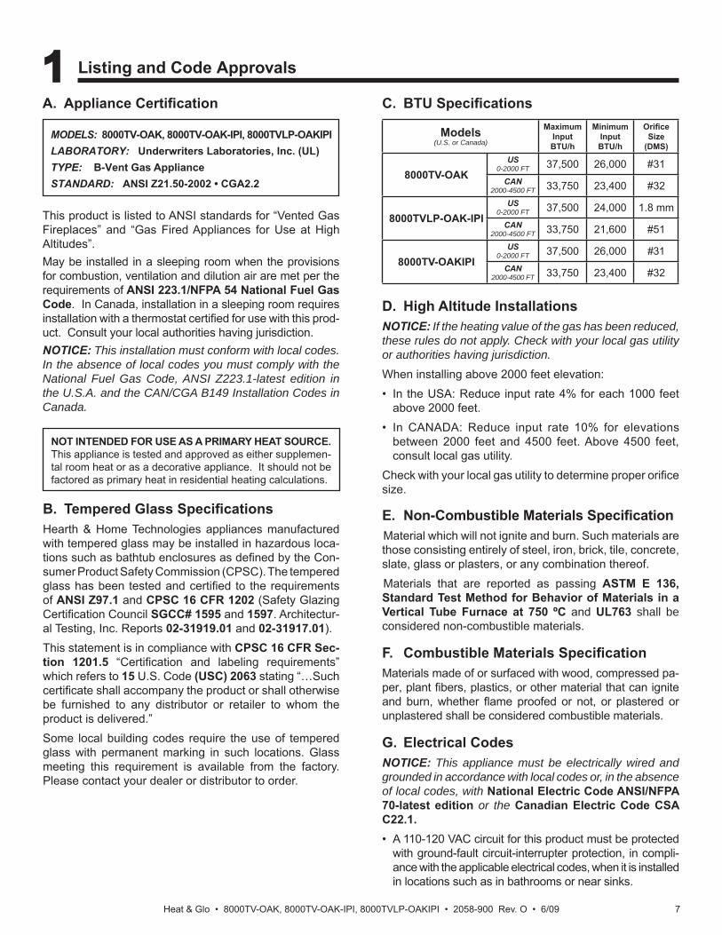
B. Tempered Glass Specifi cationsHearth & Home Technologies appliances manufactured with tempered glass may be installed in hazardous loca-tions such as bathtub enclosures as defi ned by the Con-sumer Product Safety Commission (CPSC). The tempered glass has been tested and certifi ed to the requirements of ANSI Z97.1 and CPSC 16 CFR 1202 (Safety Glazing Certifi cation Council SGCC# 1595 and 1597. Architectur-al Testing, Inc. Reports 02-31919.01 and 02-31917.01).This statement is in compliance with CPSC 16 CFR Sec-tion 1201.5 “Certifi cation and labeling requirements” which refers to 15 U.S. Code (USC) 2063 stating “…Such certifi cate shall accompany the product or shall otherwise be furnished to any distributor or retailer to whom the product is delivered.”Some local building codes require the use of tempered glass with permanent marking in such locations. Glass meeting this requirement is available from the factory. Please contact your dealer or distributor to order.
C. BTU Specifi cations
This product is listed to ANSI standards for “Vented Gas Fireplaces” and “Gas Fired Appliances for Use at High Altitudes”.May be installed in a sleeping room when the provisions for combustion, ventilation and dilution air are met per the requirements of ANSI 223.1/NFPA 54 National Fuel Gas Code. In Canada, installation in a sleeping room requires installation with a thermostat certifi ed for use with this prod-uct. Consult your local authorities having jurisdiction.NOTICE: This installation must conform with local codes. In the absence of local codes you must comply with the National Fuel Gas Code, ANSI Z223.1-latest edition in the U.S.A. and the CAN/CGA B149 Installation Codes in Canada.
A. Appliance Certifi cation
NOT INTENDED FOR USE AS A PRIMARY HEAT SOURCE. This appliance is tested and approved as either supplemen-tal room heat or as a decorative appliance. It should not be factored as primary heat in residential heating calculations.
D. High Altitude InstallationsNOTICE: If the heating value of the gas has been reduced, these rules do not apply. Check with your local gas utility or authorities having jurisdiction.When installing above 2000 feet elevation:• In the USA: Reduce input rate 4% for each 1000 feet
above 2000 feet.• In CANADA: Reduce input rate 10% for elevations
between 2000 feet and 4500 feet. Above 4500 feet, consult local gas utility.
Check with your local gas utility to determine proper orifi ce size.
1 Listing and Code Approvals
E. Non-Combustible Materials Specifi cationMaterial which will not ignite and burn. Such materials are those consisting entirely of steel, iron, brick, tile, concrete, slate, glass or plasters, or any combination thereof.Materials that are reported as passing ASTM E 136, Standard Test Method for Behavior of Materials in a Vertical Tube Furnace at 750 ºC and UL763 shall be considered non-combustible materials.
F. Combustible Materials Specifi cationMaterials made of or surfaced with wood, compressed pa-per, plant fi bers, plastics, or other material that can ignite and burn, whether fl ame proofed or not, or plastered or unplastered shall be considered combustible materials.
G. Electrical CodesNOTICE: This appliance must be electrically wired and grounded in accordance with local codes or, in the absence of local codes, with National Electric Code ANSI/NFPA 70-latest edition or the Canadian Electric Code CSA C22.1.• A 110-120 VAC circuit for this product must be protected
with ground-fault circuit-interrupter protection, in compli-ance with the applicable electrical codes, when it is installed in locations such as in bathrooms or near sinks.
MODELS: 8000TV-OAK, 8000TV-OAK-IPI, 8000TVLP-OAKIPILABORATORY: Underwriters Laboratories, Inc. (UL)TYPE: B-Vent Gas ApplianceSTANDARD: ANSI Z21.50-2002 • CGA2.2
Models(U.S. or Canada)
MaximumInputBTU/h
MinimumInputBTU/h
Orifi ce Size
(DMS)
8000TV-OAKUS
0-2000 FT 37,500 26,000 #31CAN
2000-4500 FT 33,750 23,400 #32
8000TVLP-OAK-IPIUS
0-2000 FT 37,500 24,000 1.8 mmCAN
2000-4500 FT 33,750 21,600 #51
8000TV-OAKIPIUS
0-2000 FT 37,500 26,000 #31CAN
2000-4500 FT 33,750 23,400 #32
Heat & Glo • 8000TV-OAK, 8000TV-OAK-IPI, 8000TVLP-OAKIPI • 2058-900 Rev. O • 6/098
2 Operating Instructions
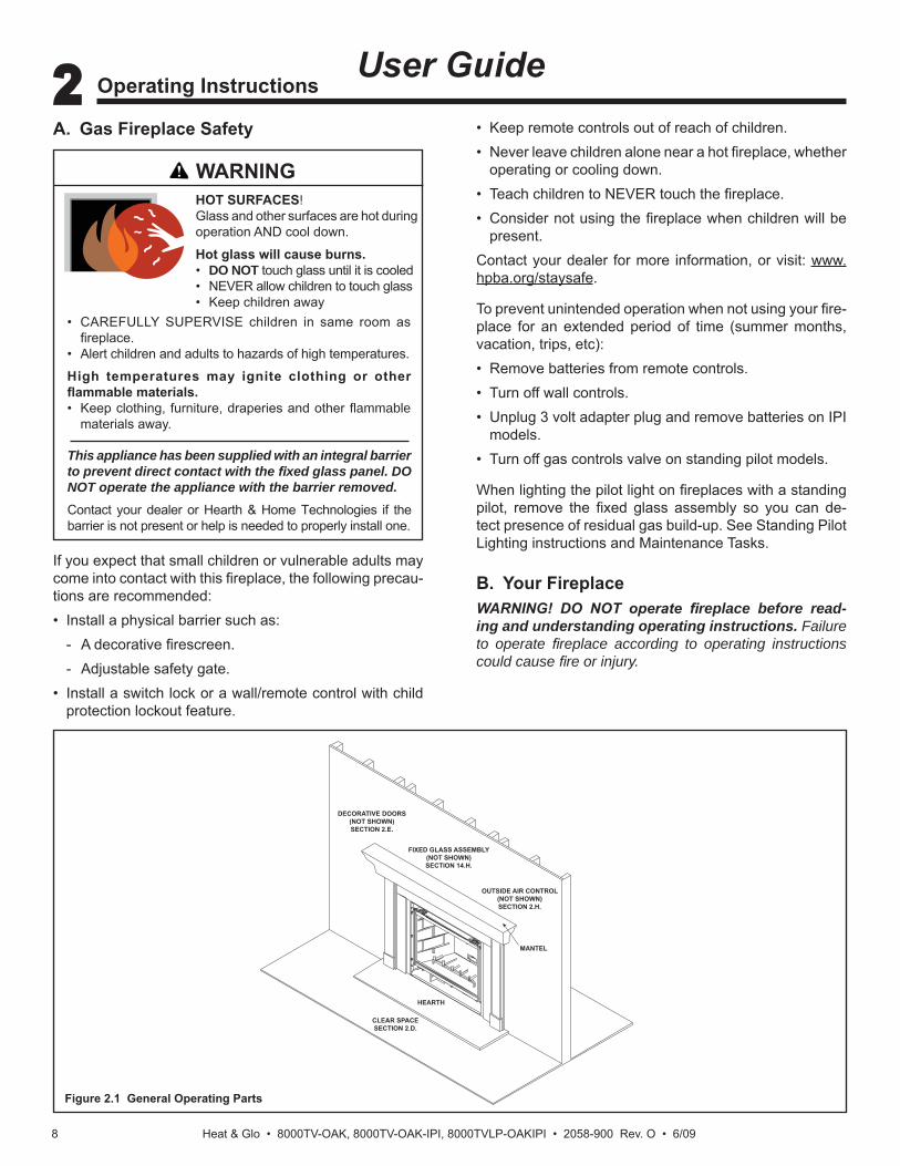
Figure 2.1 General Operating Parts
B. Your FireplaceWARNING! DO NOT operate fi replace before read-ing and understanding operating instructions. Failureto operate fi replace according to operating instructions could cause fi re or injury.
If you expect that small children or vulnerable adults may come into contact with this fi replace, the following precau-tions are recommended:• Install a physical barrier such as: - A decorative fi rescreen. - Adjustable safety gate.• Install a switch lock or a wall/remote control with child
protection lockout feature.
User GuideA. Gas Fireplace Safety
WARNING
This appliance has been supplied with an integral barrier to prevent direct contact with the fi xed glass panel. DO NOT operate the appliance with the barrier removed. Contact your dealer or Hearth & Home Technologies if the barrier is not present or help is needed to properly install one.
HOT SURFACES!Glass and other surfaces are hot during operation AND cool down.
Hot glass will cause burns.• DO NOT touch glass until it is cooled• NEVER allow children to touch glass• Keep children away
• CAREFULLY SUPERVISE children in same room as fi replace.
• Alert children and adults to hazards of high temperatures.
High temperatures may ignite clothing or other fl ammable materials.• Keep clothing, furniture, draperies and other fl ammable
materials away.
• Keep remote controls out of reach of children.• Never leave children alone near a hot fi replace, whether
operating or cooling down.• Teach children to NEVER touch the fi replace.• Consider not using the fi replace when children will be
present.Contact your dealer for more information, or visit: www.hpba.org/staysafe.
To prevent unintended operation when not using your fi re-place for an extended period of time (summer months, vacation, trips, etc):• Remove batteries from remote controls.• Turn off wall controls.• Unplug 3 volt adapter plug and remove batteries on IPI
models.• Turn off gas controls valve on standing pilot models.
When lighting the pilot light on fi replaces with a standing pilot, remove the fi xed glass assembly so you can de-tect presence of residual gas build-up. See Standing Pilot Lighting instructions and Maintenance Tasks.
OUTSIDE AIR CONTROL(NOT SHOWN)SECTION 2.H.
DECORATIVE DOORS(NOT SHOWN)SECTION 2.E.
FIXED GLASS ASSEMBLY(NOT SHOWN)SECTION 14.H.
MANTEL
HEARTH
CLEAR SPACESECTION 2.D.

Heat & Glo • 8000TV-OAK, 8000TV-OAK-IPI, 8000TVLP-OAKIPI • 2058-900 Rev. O • 6/09 9
D. Clear SpaceWARNING! DO NOT place combustible objects in front of the fi replace or block louvers. High temperatures may start a fi re. See Figure 2.2. Avoid placing candles and other heat-sensitive objects on mantel or hearth. Heat may damage these objects.
Figure 2.2 Clear Space
H. Outside Air (optional)The outside air kit supplies some fresh combustion air for your fi replace. It may help reduce the effects of negative air pressure. (See Section 9.A.)• Refer to Figure 9.1 for location of control.• Close the inlet to prevent cold drafts when the fi replace
is not being used.CAUTION! Risk of Burns! The outside air control handle is HOT when fi replace is in operation. Adjust BEFORE lighting fi re.
F. Fixed Glass AssemblySee Section 14.H.
E. Decorative Doors and FrontsWARNING! Risk of Fire! Install ONLY doors or fronts approved by Hearth & Home Technologies. Unapproved doors or fronts may cause fi replace to overheat.This fireplace has been supplied with an integral barrier to prevent direct contact with the fi xed glass panel. DO NOT operate the fi replace with the barrier removed.Contact your dealer or Hearth & Home Technologies if the barrier is not present or help is needed to properly install one.
For more information refer to the instructions supplied with your decorative door or front.
G. Remote Controls, Wall Controls and Wall Switches
Follow the instructions supplied with the control installed to operate your fi replace:
CLEAR SPACE
3 FT. IN FRONT OF FIREPLACE
I. Before Lighting FireplaceBefore operating this fi replace for the fi rst time, have a qualifi ed service technician:• Verify all shipping materials have been removed from
inside and/or underneath the fi rebox.• Review proper placement of logs, ember material and/or
other decorative materials.• Check the wiring.• Check the air shutter adjustment.• Ensure that there are no gas leaks.• Ensure that the glass is sealed and in the proper position
and that the integral barrier is in place.WARNING! Risk of Fire/Asphyxiation! DO NOT oper-ate fi replace with fi xed glass assembly removed.Determine if this fi replace has a standing pilot or an Intellifi re ignition system. Ask your dealer or open control access panel, look at gas valve assembly.• A standing pilot ignition will have a red or black ignitor
button (refer to Figure 2.3).• An Intellifi re ignition system will not have a button.
RED OR BLACKBUTTON
Figure 2.3 Ignitor Button
For safety:• Install a switch lock or a wall/remote control with child
protection lockout feature.• Keep remote controls out of reach of children.See your dealer if you have questions.
C. Fan Kit (optional)If desired, a fan kit may be added. Contact your dealer to order the correct fan kit.

Heat & Glo • 8000TV-OAK, 8000TV-OAK-IPI, 8000TVLP-OAKIPI • 2058-900 Rev. O • 6/0910
J. Lighting Instructions (IPI)The IPI system may be operated with two D-cell batteries. When using batteries, unplug the transformer. To prolong battery life, remove them when using the transformer.
1. Turn off all electric power to the appliance.
2. This appliance is equipped with an ignition device which automatically lights the burner. DO NOT try to light the burner by hand.
3. Wait fi ve (5) minutes to clear out any gas. Then smell for gas, including near the fl oor. If you smell gas, STOP! Follow “B” in the Safety Information located on the left side of this la-bel. If you do not smell gas, go to next step.
4. Turn on all electric power to the appliance.
5. To light the burner, fl ip the ON/OFF switch to the “ON” position. (The ON/OFF switch may include a wall switch if so equipped).
6. If the appliance will not operate, follow the in-structions “To Turn Off Gas to Appliance” and call your service technician or gas supplier.
LIGHTINGINSTRUCTIONS
(IPI)
TO TURN OFFGAS TO APPLIANCE
1. Turn wall control or ON/OFF switch to “OFF”.
2. Turn off all electric power to the appliance if service is to be performed.
FOR YOUR SAFETYREAD BEFORE LIGHTING
WARNING: If you do not follow these instructions exactly, a fi re or explosion may result causing property damage, personal injury or loss of life.
CAUTION:
NOT FOR USE WITH SOLID FUEL
WARNING:
593-913F
GASVALVE
For additional information on operating your Hearth & Home Technologies fi replace, please refer to www.fi replaces.com.
A. This appliance is equipped with an intermittent pilot ignition (IPI) device which automatically lights the burn-er. DO NOT try to light the burner by hand.
B. BEFORE LIGHTING, smell all around the appliance area for gas. Be sure to smell next to the fl oor because some gas is heavier than air and will settle on the fl oor.
WHAT TO DO IF YOU SMELL GAS• DO NOT try to light any appliance.
• DO NOT touch any electric switch; do not use any phone in your building.
DO NOT CONNECT 110 VAC TO THE CONTROL VALVE.Improper installation, adjustment, al-teration, service or maintenance can cause injury or property damage. Re-fer to the owner’s information manual provided with this appliance.
This appliance needs fresh air for safe operation and must be installed so there are provisions for adequate combustion and ventilation air.
If not installed, operated, and main-tained in accordance with the man-ufacturer’s instructions, this product could expose you to substances in fuel or fuel combustion which are known to the State of California to cause can-cer, birth defects, or other reproductive harm.
Keep burner and control compartment clean. See installation and operating instructions accompanying appliance.
Hot while in operation. DO NOT touch. Keep children, clothing, furniture, gaso-line and other liquids having fl ammable vapors away.
DO NOT operate the appliance with fi xed glass assembly removed, cracked or broken. Replacement of the fi xed glass assembly should be done by a licensed or qualifi ed service person.
• Immediately call your gas supplier from a neighbor’s phone. Follow the gas supplier’s instructions.
• If you cannot reach your gas sup-plier, call the fi re department.
C. DO NOT use this appliance if any part has been under water. Imme-diately call a qualifi ed service tech-nician to inspect the appliance and to replace any part of the control system and any gas control which has been under water.
For use with natural gas and propane. A conversion kit, as supplied by the manufacturer, shall be used to convert this appliance to the alternate fuel.
Also Certifi ed for Installation in a Bedroom or a Bedsitting Room.For assistance or additional informa-tion, consult a qualifi ed installer, ser-vice agency or the gas supplier.
Final inspection by
Heat & Glo • 8000TV-OAK, 8000TV-OAK-IPI, 8000TVLP-OAKIPI • 2058-900 Rev. O • 6/09 11
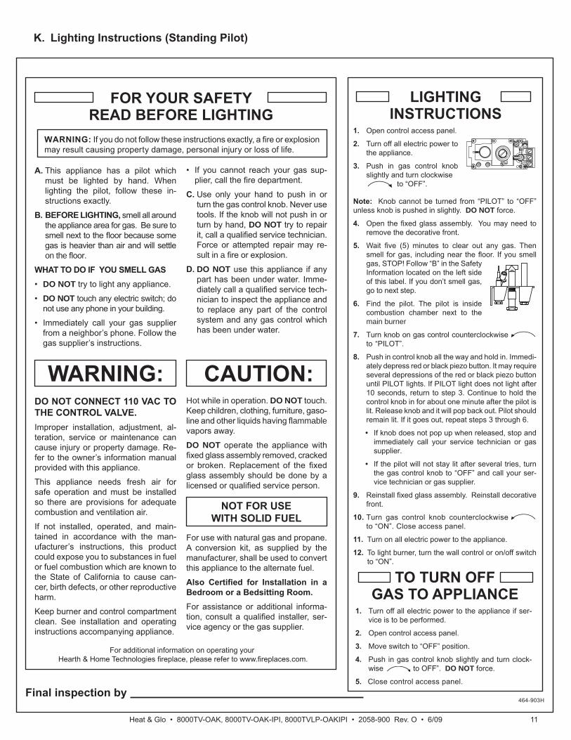
K. Lighting Instructions (Standing Pilot)
1. Turn off all electric power to the appliance if ser-vice is to be performed.
2. Open control access panel.
3. Move switch to “OFF” position.
4. Push in gas control knob slightly and turn clock-wise to OFF”. DO NOT force.
5. Close control access panel.
1. Open control access panel.
2. Turn off all electric power to the appliance.
3. Push in gas control knob slightly and turn clockwise
to “OFF”.
Note: Knob cannot be turned from “PILOT” to “OFF” unless knob is pushed in slightly. DO NOT force.
4. Open the fi xed glass assembly. You may need to remove the decorative front.
5. Wait fi ve (5) minutes to clear out any gas. Then smell for gas, including near the fl oor. If you smell gas, STOP! Follow “B” in the Safety Information located on the left side of this label. If you don’t smell gas, go to next step.
6. Find the pilot. The pilot is inside combustion chamber next to the main burner
7. Turn knob on gas control counterclockwiseto “PILOT”.
8. Push in control knob all the way and hold in. Immedi-ately depress red or black piezo button. It may require several depressions of the red or black piezo button until PILOT lights. If PILOT light does not light after 10 seconds, return to step 3. Continue to hold the control knob in for about one minute after the pilot is lit. Release knob and it will pop back out. Pilot should remain lit. If it goes out, repeat steps 3 through 6.
• If knob does not pop up when released, stop and immediately call your service technician or gas supplier.
• If the pilot will not stay lit after several tries, turn the gas control knob to “OFF” and call your ser-vice technician or gas supplier.
9. Reinstall fi xed glass assembly. Reinstall decorative front.
10. Turn gas control knob counterclockwise to “ON”. Close access panel.
11. Turn on all electric power to the appliance.
12. To light burner, turn the wall control or on/off switch to “ON”.
LIGHTINGINSTRUCTIONS
TO TURN OFFGAS TO APPLIANCE
464-903H
FOR YOUR SAFETYREAD BEFORE LIGHTING
WARNING: If you do not follow these instructions exactly, a fi re or explosion may result causing property damage, personal injury or loss of life.
CAUTION:
NOT FOR USE WITH SOLID FUEL
WARNING:
For additional information on operating your Hearth & Home Technologies fi replace, please refer to www.fi replaces.com.
A. This appliance has a pilot which must be lighted by hand. When lighting the pilot, follow these in-structions exactly.
B. BEFORE LIGHTING, smell all around the appliance area for gas. Be sure to smell next to the fl oor because some gas is heavier than air and will settle on the fl oor.
WHAT TO DO IF YOU SMELL GAS• DO NOT try to light any appliance.
• DO NOT touch any electric switch; do not use any phone in your building.
• Immediately call your gas supplier from a neighbor’s phone. Follow the gas supplier’s instructions.
DO NOT CONNECT 110 VAC TO THE CONTROL VALVE.Improper installation, adjustment, al-teration, service or maintenance can cause injury or property damage. Re-fer to the owner’s information manual provided with this appliance.
This appliance needs fresh air for safe operation and must be installed so there are provisions for adequate combustion and ventilation air.
If not installed, operated, and main-tained in accordance with the man-ufacturer’s instructions, this product could expose you to substances in fuel or fuel combustion which are known to the State of California to cause can-cer, birth defects, or other reproductive harm.
Keep burner and control compartment clean. See installation and operating instructions accompanying appliance.
Hot while in operation. DO NOT touch. Keep children, clothing, furniture, gaso-line and other liquids having fl ammable vapors away.
DO NOT operate the appliance with fi xed glass assembly removed, cracked or broken. Replacement of the fi xed glass assembly should be done by a licensed or qualifi ed service person.
• If you cannot reach your gas sup-plier, call the fi re department.
C. Use only your hand to push in or turn the gas control knob. Never use tools. If the knob will not push in or turn by hand, DO NOT try to repair it, call a qualifi ed service technician. Force or attempted repair may re-sult in a fi re or explosion.
D. DO NOT use this appliance if any part has been under water. Imme-diately call a qualifi ed service tech-nician to inspect the appliance and to replace any part of the control system and any gas control which has been under water.
For use with natural gas and propane. A conversion kit, as supplied by the manufacturer, shall be used to convert this appliance to the alternate fuel.
Also Certifi ed for Installation in a Bedroom or a Bedsitting Room.For assistance or additional informa-tion, consult a qualifi ed installer, ser-vice agency or the gas supplier.
Final inspection by

Heat & Glo • 8000TV-OAK, 8000TV-OAK-IPI, 8000TVLP-OAKIPI • 2058-900 Rev. O • 6/0912
Initial Break-in Procedure• The fireplace should be run three to four hours
continuously on high.• Turn the fi replace off and allow it to completely cool.• Remove fi xed glass assembly. See Section 14.H.• Clean fi xed glass assembly. See Section 3.• Replace the fi xed glass assembly and run continuously
on high an additional 12 hours.This cures the materials used to manufacture the fi re-place.NOTICE! Open windows for air circulation during fi re-place break-in.
• Some people may be sensitive to smoke and odors.• Smoke detectors may activate.
L. After Fireplace is Lit
M. Frequently Asked Questions
ISSUE SOLUTIONS
Condensation on the glass This is a result of gas combustion and temperature variations. As the appliance warms, this condensation will disappear.
Blue fl ames This is a result of normal operation and the fl ames will begin to yellow as the appliance is al-lowed to burn for 20 to 40 minutes.
Odor from applianceWhen fi rst operated, this appliance may release an odor for the fi rst several hours. This is caused by the curing of the paint and the burning off of any oils remaining from manufacturing. Odor may also be released from fi nishing materials and adhesives used around the appliance.
Film on the glassThis is a normal result of the curing process of the paint and logs. Glass should be cleaned within 3 to 4 hours of initial burning to remove deposits left by oils from the manufacturing process. A non-abrasive cleaner such as gas fi replace glass cleaner may be necessary. See your dealer.
Metallic noiseNoise is caused by metal expanding and contracting as it heats up and cools down, similar to the sound produced by a furnace or heating duct. This noise does not affect the operation or longevity of the appliance.
Is it normal to see the pilot fl ame burn continually?
In an intermittent pilot ignition system (IPI), the pilot fl ame should turn off when appliance is turned off. Some optional control systems available with IPI models may allow pilot fl ame to remain lit. In a standing pilot system the pilot will always stay on.

Heat & Glo • 8000TV-OAK, 8000TV-OAK-IPI, 8000TVLP-OAKIPI • 2058-900 Rev. O • 6/09 13
Glass CleaningFrequency: SeasonallyBy: HomeownerTools Needed: Protective gloves, glass cleaner, drop cloth and a stable work surface.CAUTION! Handle fi xed glass assembly with care. Glass is breakable.
• Avoid striking, scratching or slamming glass• Avoid abrasive cleaners• DO NOT clean glass while it is hot
• Prepare a work area large enough to accommodate fi xed glass assembly and door frame by placing a drop cloth on a fl at, stable surface.
Note: Fixed glass assembly and gasketing may have res-idue that can stain carpeting or fl oor surfaces.• Remove door or decorative front from fi replace and set
aside on work surface.• See Section 14.H for instructions to remove fi xed glass
assembly.• Clean glass with a non-abrasive commercially available
cleaner.- Light deposits: Use a soft cloth with soap and water- Heavy deposits: Use commercial fireplace glass
cleaner (consult with your dealer)• Carefully set fi xed glass assembly in place on fi replace.
Hold glass in place with one hand and secure glass latches with the other hand.
• Reinstall door or decorative front.
3 Maintenance and Service
A. Maintenance Tasks-Homeowner
The following tasks may be performed annually by the homeowner. If you are uncomfortable performing any of the listed tasks, please call your dealer for a service ap-pointment.More frequent cleaning may be required due to lint from carpeting or other factors. Control compartment, burner and circulating air passageway of the fi replace must be kept clean.CAUTION! Risk of Burns! The fi replace should be turned off and cooled before servicing.
When properly maintained, your fi replace will give you many years of trouble-free service. We recommend an-nual service by a qualifi ed service technician.
Doors, Surrounds, FrontsFrequency: AnnuallyBy: HomeownerTools needed: Protective gloves, stable work surface• Assess condition of screen and replace as necessary. • Inspect for scratches, dents or other damage and repair
as necessary.• Check that louvers are not blocked.
• Vacuum and dust surfaces.
Remote ControlFrequency: SeasonallyBy: HomeownerTools needed: Replacement batteries and remote con-trol instructions.• Locate remote control transmitter and receiver.• Verify operation of remote. Refer to remote control
operation instructions for proper calibration and setup procedure.
• Place batteries as needed in remote transmitters and battery-powered receivers.
• Place remote control out of reach of children.If not using your fi replace for an extended period of time (summer months, vacations/trips, etc), to prevent unin-tended operation:• Remove batteries from remote controls.• Unplug 3 volt adapter plug on IPI models.
Any safety screen or guard removed for servicing must be replaced prior to operating the fi replace.
Installation and repair should be done by a qualifi ed service technician only. The fi replace should be inspected before use and at least annually by a professional service person.

Heat & Glo • 8000TV-OAK, 8000TV-OAK-IPI, 8000TVLP-OAKIPI • 2058-900 Rev. O • 6/0914
VentingFrequency: SeasonallyBy: HomeownerTools needed: Protective gloves and safety glasses.• Inspect venting and termination cap for blockage or
obstruction such plants, bird nests, leaves, snow, debris, etc.
• Verify termination cap clearance to subsequent construc-tion. See Section 6.
• Inspect for corrosion or separation.• Verify weather stripping, sealing and fl ashing remains
intact.
• Inspect draft shield to verify it is not damaged or missing.
B. Maintenance Tasks-Qualifi ed Service Technician
The following tasks must be performed by a qualifi ed ser-vice technician.
Gasket Seal and Glass Assembly InspectionFrequency: AnnuallyBy: Qualifi ed Service TechnicianTools needed: Protective gloves, drop cloth and a stable work surface.• Inspect gasket seal and its condition.• Inspect fi xed glass assembly for scratches and nicks that
can lead to breakage when exposed to heat.• Confi rm there is no damage to glass or glass frame.
Replace as necessary.• Verify that fi xed glass assembly is properly retained and
attachment components are intact and not damaged. Replace as necessary.
LogsFrequency: AnnuallyBy: Qualifi ed Service TechnicianTools needed: Protective gloves.• Inspect for damaged or missing logs. Replace as necessary.
Refer to Section 14 for log placement instructions.• Verify correct log placement and no fl ame impingement
causing sooting. Correct as necessary.
FireboxFrequency: AnnuallyBy: Qualifi ed Service TechnicianTools needed: Protective gloves, sandpaper, steel wool, cloths, mineral spirits, primer and touch-up paint.• Inspect for paint condition, warped surfaces, corrosion
or perforation. Sand and repaint as necessary.• Replace fi replace if fi rebox has been perforated.
Control Compartment and Firebox TopFrequency: AnnuallyBy: Qualifi ed Service TechnicianTools needed: Protective gloves, vacuum cleaner, dust cloths• Vacuum and wipe out dust, cobwebs, debris or pet hair.
Use caution when cleaning these areas. Screw tips that have penetrated the sheet metal are sharp and should be avoided.
• Remove all foreign objects.• Verify unobstructed air circulation.
Burner Ignition and OperationFrequency: AnnuallyBy: Qualifi ed Service TechnicianTools needed: Protective gloves, vacuum cleaner, whisk broom, fl ashlight, voltmeter, indexed drill bit set, and a manometer.• Verify burner is properly secured and aligned with pilot
or igniter.• Clean off burner top, inspect for plugged ports, corrosion
or deterioration. Replace burner if necessary.• Replace Glowing embers with new dime-size pieces.
DO NOT block ports or obstruct lighting paths. Refer to Section 14 for proper ember placement.
• Verify batteries have been removed from battery back-up IPI systems to prevent premature battery failure or leaking.
• Check for smooth lighting and ignition carryover to all ports. Verify that there is no ignition delay.
• Inspect for lifting or other fl ame problems.• Verify air shutter setting is correct. See Section 14 for
required air shutter setting. Verify air shutter is clear of dust and debris.
• Inspect orifi ce for soot, dirt and corrosion. Verify orifi ce size is correct. See Service Parts List for proper orifi ce sizing.
• Verify manifold and inlet pressures. Adjust regulator as required.
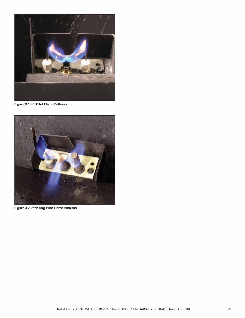
• Inspect pilot fl ame pattern and strength. See Figures 3.1 and 3.2 for proper pilot fl ame pattern. Clean or replace orifi ce spud as necessary.
• Inspect thermocouple/thermopile or IPI fl ame sensing rod for soot, corrosion and deterioration. Clean with emery cloth or replace as required.
• Verify thermocouple/thermopile millivolt output. Replace pilot as necessary. (Standing pilot only)
• Verify that there is not a short in fl ame sense circuit by checking continuity between pilot hood and fl ame sense rod. Replace pilot as necessary. (IPI only)
Heat & Glo • 8000TV-OAK, 8000TV-OAK-IPI, 8000TVLP-OAKIPI • 2058-900 Rev. O • 6/09 15
Figure 3.1 IPI Pilot Flame Patterns
Figure 3.2 Standing Pilot Flame Patterns

Heat & Glo • 8000TV-OAK, 8000TV-OAK-IPI, 8000TVLP-OAKIPI • 2058-900 Rev. O • 6/0916
4 Getting Started
A. Typical Appliance SystemNOTICE: Illustrations and photos refl ect typical installations and are for design purposes only. Illustrations/diagrams are not drawn to scale. Actual product may vary from pictures in manual
CEILING FIRESTOPON FLOOR OF ATTIC(SECTION 8.B)
VERTICAL TERMINATION CAP (SECTION 4.D)
VENT PIPE PENETRATES ROOFPREFERABLY WITHOUT AFFECTINGROOF RAFTERS (SECTION 8.B)
FRAMING HEADED OFFIN CEILING JOISTS(SECTION 8.B)
GAS LINESECTION
MANTEL AND MANTEL LEG(SECTION 5.D)
SURROUND
HEARTH EXTENSION
VENT PIPE (SECTIONS 6 and 7)
OPTIONALWALL SWITCH
ATTIC INSULATION SHIELD (NOT SHOWN) MUSTBE USED HERE TO KEEP INSULATION AWAY FROM VENT PIPE IF ATTIC IS INSULATED (SECTION 10.D)
STORM COLLAR(SECTION 4.D)
NON-COMBUSTIBLE ROOF FLASHING MAINTAINS MINIMUM CLEARANCE AROUND PIPE (SECTION 4.D)
FRAMING/HEADER (SECTION 5)
Figure 4.1 Typical System
Installer Guide
Heat & Glo • 8000TV-OAK, 8000TV-OAK-IPI, 8000TVLP-OAKIPI • 2058-900 Rev. O • 6/09 17
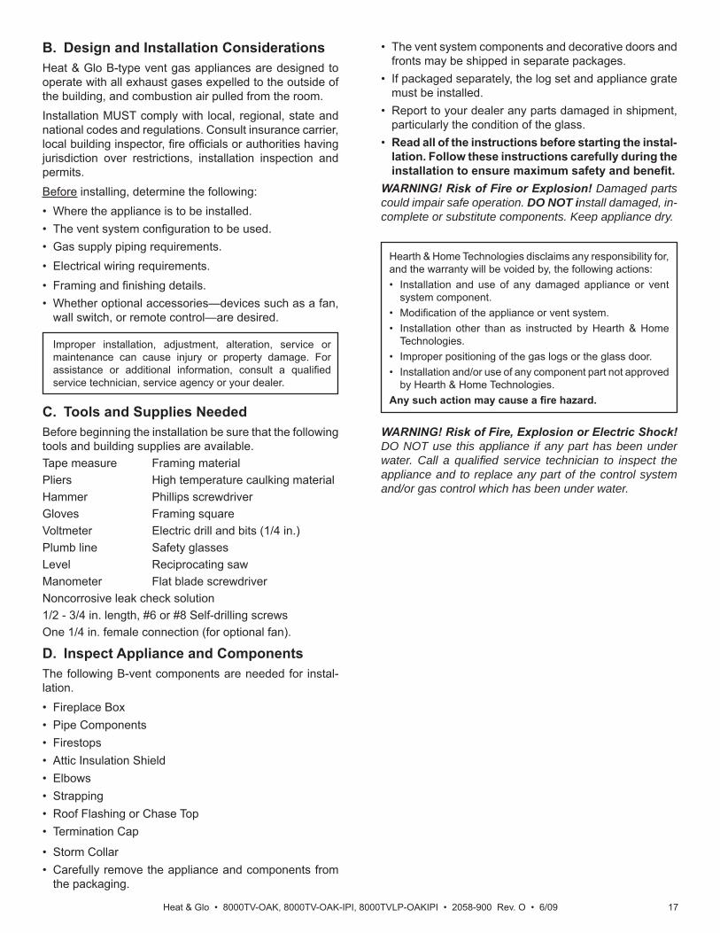
B. Design and Installation ConsiderationsHeat & Glo B-type vent gas appliances are designed to operate with all exhaust gases expelled to the outside of the building, and combustion air pulled from the room.Installation MUST comply with local, regional, state and national codes and regulations. Consult insurance carrier, local building inspector, fi re offi cials or authorities having jurisdiction over restrictions, installation inspection and permits.Before installing, determine the following:• Where the appliance is to be installed.• The vent system confi guration to be used.• Gas supply piping requirements.• Electrical wiring requirements.• Framing and fi nishing details.• Whether optional accessories—devices such as a fan,
wall switch, or remote control—are desired.
D. Inspect Appliance and ComponentsThe following B-vent components are needed for instal-lation.• Fireplace Box• Pipe Components• Firestops• Attic Insulation Shield• Elbows• Strapping• Roof Flashing or Chase Top• Termination Cap
• Storm Collar• Carefully remove the appliance and components from
the packaging.
C. Tools and Supplies NeededBefore beginning the installation be sure that the following tools and building supplies are available.Tape measure Framing materialPliers High temperature caulking materialHammer Phillips screwdriverGloves Framing squareVoltmeter Electric drill and bits (1/4 in.)Plumb line Safety glassesLevel Reciprocating sawManometer Flat blade screwdriverNoncorrosive leak check solution1/2 - 3/4 in. length, #6 or #8 Self-drilling screwsOne 1/4 in. female connection (for optional fan).
WARNING! Risk of Fire, Explosion or Electric Shock! DO NOT use this appliance if any part has been under water. Call a qualifi ed service technician to inspect the appliance and to replace any part of the control system and/or gas control which has been under water.
Improper installation, adjustment, alteration, service or maintenance can cause injury or property damage. For assistance or additional information, consult a qualifi ed service technician, service agency or your dealer.
Hearth & Home Technologies disclaims any responsibility for, and the warranty will be voided by, the following actions:• Installation and use of any damaged appliance or vent
system component.• Modifi cation of the appliance or vent system.• Installation other than as instructed by Hearth & Home
Technologies.• Improper positioning of the gas logs or the glass door.• Installation and/or use of any component part not approved
by Hearth & Home Technologies.Any such action may cause a fi re hazard.
• The vent system components and decorative doors and fronts may be shipped in separate packages.
• If packaged separately, the log set and appliance grate must be installed.
• Report to your dealer any parts damaged in shipment, particularly the condition of the glass.
• Read all of the instructions before starting the instal-lation. Follow these instructions carefully during the installation to ensure maximum safety and benefi t.
WARNING! Risk of Fire or Explosion! Damaged parts could impair safe operation. DO NOT install damaged, in-complete or substitute components. Keep appliance dry.

Heat & Glo • 8000TV-OAK, 8000TV-OAK-IPI, 8000TVLP-OAKIPI • 2058-900 Rev. O • 6/0918
Figure 4.2
E. Negative PressureWARNING! Asphyxiation Risk! Negative pressure can cause spillage of combustion fumes and soot. Fireplaceneeds to draft properly for safety.Draft is the pressure difference needed to vent fi replaces successfully. Considerations for successful draft include:• Preventing negative pressure• Location of fi replace and chimney
Negative pressure results from the imbalance of air available for the fi replace to operate properly. Causes for this imbalance include:
• Exhaust fans (kitchen, bath, etc.)• Range hoods• Combustion air requirements for furnaces, water heaters
and other combustion appliances• Clothes dryers• Location of return-air to furnace or air conditioning• Imbalances of the HVAC air handling system• Upper level air leaks (recessed lighting, attic hatch
opening, duct leaks)To minimize the effects of negative air pressure, the fol-lowing must be considered:
• Install the fresh air kit. Install the intake on the side of the house towards prevailing winds during the heating season.
• Ensure adequate outdoor air is supplied for combustion appliances and exhaust equipment.
• Ensure furnace and air conditioning return vents are not located in the immediate vicinity of the fi replace.
• Avoid installing the fi replace near doors, walkways or small isolated spaces.
• Recessed lighting should be of “sealed can” design; attic hatches weather stripped or sealed; and attic mounted ductwork and air handler joints and seams taped or sealed.
• Basement installations should be avoided due to stack effect. Stack effect creates negative pressure in lower levels. Hearth & Home Technologies recommends the use of direct vent fi replaces in basements.
Location of the fi replace and chimney will affect perfor-mance. As shown in Figure 4.2, the chimney should:
• Be installed through the warm space enclosed by the building envelope. This helps to produce more draft, especially during lighting and die-down of the fi re.
• Penetrate the highest part of the roof. This minimizes the effects of wind turbulence.
• Be located away from trees, adjacent structures, uneven roof lines and other obstructions.
Offsets can restrict draft so their use should be minimized. Consider the fi replace location relative to fl oor and ceiling and attic joists.
RecommendedLocation
MarginalLocation
LocationNot
Recommended
RecommendedLocation
Location NOT Recommended
Multi-level Roofs
WindwardLeeward

Heat & Glo • 8000TV-OAK, 8000TV-OAK-IPI, 8000TVLP-OAKIPI • 2058-900 Rev. O • 6/09 19
5 Framing and Clearances
A. Selecting Appliance LocationWhen selecting a location for the appliance it is important to consider the required clearances to walls (see Figure 5.1).WARNING! Risk of Fire or Burns! Provide adequate clearance around air openings and for service access. Due to high temperatures, the appliance should be locat-ed out of traffi c and away from furniture and draperies.
NOTICE: Illustrations refl ect typical installations and are FOR DESIGN PURPOSES ONLY. Illustrations/diagrams are not drawn to scale. Actual installation may vary due to individual design preference.
Figure 5.1 Appliance Locations
A B C D E F GInches 55-7/8 1/2 79 49 Min. 1 37-3/8 22
Millimeters 1419 13 2007 1245 25 949 559
D
C
G
E
D
A
D
A
B
F

Heat & Glo • 8000TV-OAK, 8000TV-OAK-IPI, 8000TVLP-OAKIPI • 2058-900 Rev. O • 6/0920
C
B
D
A
B. Constructing the Appliance ChaseA chase is a vertical box-like structure built to enclose the gas appliance and/or its vent system. In cooler climates the vent should enclosed inside the chase.NOTICE: Treatment of ceiling fi restops and wall shield fi restops and construction of the chase may vary with the type of building. These instructions are not substitutes for the requirements of local building codes. Therefore, you MUST check local building codes to determine the requirements to these steps.Chases should be constructed in the manner of all out-side walls of the home to prevent cold air drafting prob-lems. The chase should not break the outside building envelope in any manner.Walls, ceiling, base plate and cantilever fl oor of the chase should be insulated. Vapor and air infi ltration barriers should be installed in the chase as per regional codes for the rest of the home. Additionally, in regions where cold air infi ltration may be an issue, the inside surfaces may be sheetrocked and taped for maximum air tightness.
Figure 5.2 Clearances to Combustibles
C. ClearancesNOTICE: Install appliance on hard metal or wood surfaces extending full width and depth. DO NOT install directly on carpeting, vinyl, tile or any combustible material other than wood.WARNING! Risk of Fire! Maintain specifi ed air space clearances to appliance and vent pipe:• Insulation and other materials must be secured to prevent
accidental contact.• The chase must be properly blocked to prevent blown
insulation or other combustibles from entering and making contact with fi replace or chimney.
• Failure to maintain airspace may cause overheating and a fi re.
To further prevent drafts, the wall shield and ceiling fi re-stops should be caulked with high temperature caulk to seal gaps. Gas line holes and other openings should be caulked with high temp caulk or stuffed with unfaced in-sulation. If the appliance is being installed on a cement slab, a layer of plywood may be placed underneath to prevent conducting cold up into the room.
* Adjust framing dimensions for interior sheathing (such as sheetrock)
* MINIMUM FRAMING DIMENSIONS
A B C D E F G H I JRough
Opening (Vent Pipe)
Rough Opening(Height)
Rough Opening(Depth)
Rough Opening(Width)
Clearanceto Ceiling
Combustible Floor
CombustibleFlooring
BehindAppliance
Sides of Appliance
Front of Appliance
Inches 10 40-1/2 22 49 32 0 0 1/2 1/2 36
mm 254 1029 559 1245 813 0 0 13 13 914
J
I
H
E
F
TOP OFHOOD
TOCEILING
G

Heat & Glo • 8000TV-OAK, 8000TV-OAK-IPI, 8000TVLP-OAKIPI • 2058-900 Rev. O • 6/09 21
D. Mantel and Wall ProjectionsWARNING! Risk of Fire! Comply with all minimum clear-ances as specifi ed. Framing or fi nishing material closer than the minimums listed must be constructed entirely of noncom-bustible materials (i.e., steel studs, concrete board, etc).
Figure 5.3 Minimum Vertical and Maximum Horizontal Dimensions of Combustibles
Figure 5.4 Combustible Mantel Leg or Wall Projections (Acceptable on both sides of opening)
Combustible Mantels
Combustible Mantel Legs or Wall Projections
1/2 INCH(13 mm)
32 IN.(813 mm)
TOP OF HOOD
12 IN.(305 mm)
NON-COMBUSTIBLEMATERIAL ONLY
13 IN.(330 mm)
CEILING
TOP FRONT EDGE OF FIREPLACE
Note: Clearance from opening to perpendicular wall.
1 in.MIN.
3 in.MIN.
3 ft.MAX.
TOP VIEW

Heat & Glo • 8000TV-OAK, 8000TV-OAK-IPI, 8000TVLP-OAKIPI • 2058-900 Rev. O • 6/0922
A. Vent Termination Minimum Clearances
Roof Pitch H (Min.) Ft.Flat to 6/12...........................................................1.0*Over 6/12 to 7/12 .................................................1.25*Over 7/12 to 8/12 .................................................1.5*Over 8/12 to 9/12 .................................................2.0*Over 9/12 to 10/12 ...............................................2.5Over 10/12 to 11/12 .............................................3.25Over 11/12 to 12/12 .............................................4.0Over 12/12 to 14/12 .............................................5.0Over 14/12 to 16/12 .............................................6.0Over 16/12 to 18/12 .............................................7.0Over 18/12 to 20/12 .............................................7.5Over 20/12 to 21/12 .............................................8.0
Figure 6.1 Minimum Height From Roof To Lowest Discharge Opening
* 3 foot minimum in snow regions
6 Termination Locations
Fire Risk.Maintain vent clearance to combustibles as specifi ed.• DO NOT pack air space with insulation or other
materials.Failure to keep insulation or other materials away from vent pipe may cause overheating and fi re.
WARNING
VERTICALWALL
LISTED B-VENTTERMINATION
CAP
12X
ROOF PITCHIS X/ 12
LOWESTDISCHARGE
OPENING
H (MIN.) - MINIMUM HEIGHT FROM ROOFTO LOWEST DISCHARGE OPENING
8 FEET
Figure 6.2 Staggered Termination Caps
Gas, Wood or Fuel OilTermination Cap
B
GasTermination
Cap **
A *
* If using decorative cap cover(s), this distance may need to beincreased. Refer to the installation instructions supplied with thedecorative cap cover.
** In a staggered installation with both gas and wood terminations, thewood termination cap must be higher than the gas termination cap.
A B6 in. (minimum) up to 20 in.
152 mm/508 mm18 in. minimum
457 mm20 in. and over 0 in. minimum

Heat & Glo • 8000TV-OAK, 8000TV-OAK-IPI, 8000TVLP-OAKIPI • 2058-900 Rev. O • 6/09 23
7 Vent Information and Diagrams
B. Vent System Confi gurationCAUTION! Risk of Fire! ALL vent confi guration specifi -cations MUST be followed. This product is tested and listed to these specifi cations. Appliance performance will suffer if specifi cations are not followed.
Rise to Run Ratio = 2:1Maximum Total Horizontal Run = 15 FeetMinimum Total Vertical Rise = 9 FeetMaximum Total Vertical Rise = 30 FeetMaximum Number of Elbows: Two 90º or Four 45º
Figure 7.1
A. Vent GuidelinesWARNING! Fire Risk/Asphyxiation! This appliance requires the specifi ed pipe for operation. Incorrect pipe may cause spill-age, condensation and overheating.
Figure 7.2
These models require the following size B-vent double wall, or single wall rigid or fl ex vent pipe.
METALPLUMBERS' STRAP
MAXIMUM HORIZONTAL RUN IS 50%OF VERTICAL. HORIZONTAL RUNCANNOT BE MORE THAN 15 FT.
VENT SUPPORTS ARE PER VENT
MANUFACTURER'SSPECIFICATIONS.
METAL PLUMBER’S
STRAP 9 FEETMINIMUM
VENT SUPPORTS ARE PER VENT MANUFACTURER’S
SPECIFICATIONS
MINIMUM CLEARANCESARE PER VENT
MANUFACTURER’SSPECIFICATIONS
• Follow pipe manufacturer’s installation guidelines when installing the appliance.
WARNING! Fire Risk/Explosion/Asphyxiation! DO NOT connect this gas appliance to a chimney fl ue serving a separate solid-fuel or gas burning appliance.• Vent this appliance directly outside.• Use separate vent system for this appliance. May impair safe operation of this appliance or other appli-ances connected to the fl ue.
WARNING! Risk of Fire or Explosion! Insulation and oth-er combustibles must not infringe on clearances.
• ALWAYS maintain specifi ed clearances around venting and fi restop systems.
• Install fi restops as specifi ed.Failure to keep insulation or other material away from vent pipe may cause fi re.
Figure 7.3
45 DEGREESELBOW
90 DEGREESELBOW
OFFSETS EXCEEDING45 DEGREES ADAPT
HORIZONTAL LIMITATIONS
MAXIMUMHORIZONTAL
15 FEET
MINIMUMVERTICAL
9 FEET
Note: Maximum horizontal distance is 50% vertical vent height or up to 15 feet.
Note: Horizontal runs require 1/4 in. rise per foot run.
Models Pipe Size8000TV-OAK 6 inch
Note: A rise of 1/4 inch per foot of horizontal run is required.
Heat & Glo • 8000TV-OAK, 8000TV-OAK-IPI, 8000TVLP-OAKIPI • 2058-900 Rev. O • 6/0924
A. Pipe Clearances to CombustiblesVent clearances are per vent manufacturer’s specifi ca-tions. MUST be Listed B-Vent pipe. WARNING! Risk of Fire! Maintain air space clearance to vent. DO NOT pack insulation or other combustibles:
• Between ceiling fi restops• Between wall shield fi restops• Around vent system
Failure to keep insulation or other material away from vent pipe may cause over heating and fi re.
8 Vent Clearances and Framing
B. Wall and Ceiling Penetration FramingFor a wall or ceiling penetration consult B-vent pipe manufacturer’s instructions to provide adequate clear-ances. Use same size framing materials as those used in the wall or ceiling construction. Firestop spacers must be used in wall and ceiling penetrations per the B-Vent pipe manufacturer’s specifi cations and national, regional and local codes.Note: MUST terminate vertically.
C. Vertical Penetration FramingWARNING! Fire Risk. DO NOT allow loose materials or insulation to touch vent. Hearth & Home Technologies Inc. requires the use of an attic shield.The National Fuel Gas Code ANSI Z223.1 and NFPA 54 requires an attic shield constructed of 26 gauge minimum metal that extends at least 2 in. (51 mm) above insulation.Attic shields must meet specifi ed clearance and be se-cured in place.Use B-vent manufacturer’s fi restops to provide adequate clearances.

Heat & Glo • 8000TV-OAK, 8000TV-OAK-IPI, 8000TVLP-OAKIPI • 2058-900 Rev. O • 6/09 25
A. Installing Outside Air Kit Damper Assem-bly
CAUTION! Risk of Cuts/Abrasions/Flying Debris. Wear protective gloves and safety glasses during instal-lation. Sheet metal edges are sharp.WARNING! Risk of Fire/Asphyxiation. DO NOT draw out-side combustion air from:
• Wall, fl oor or ceiling cavity. • Enclosed space such as an attic or garage. • Close proximity to exhaust vents or chimneys.Fumes or odor may result.• Remove and discard cover plate or knockout from side
of appliance.• Open air kit damper slightly.• Locate door hinge toward back of appliance (see Figure
9.1).
9 Appliance Preparation
Figure 9.2 Outside Air Kit Installation
Figure 9.1 Damper Assembly and Handle
HANDLE
HINGE
DOOR
B. Gas and Electrical ConnectionsIf applicable, ensure that gas and electrical connections are installed at this time. Refer to Sections 11 (Gas Information) and 12 (Electrical Information).
• Attach damper assembly to appliance using screws provided (see Figure 9.2).
• Insert narrow end of handle through tab and into upper slot of door.
• Check handle operation. Pull handle out to open, and in to close.
C. Securing and Leveling the ApplianceWARNING! Risk of Fire! Prevent contact with:
• Sagging or loose insulation• Insulation backing or plastic• Framing and other combustible materialsBlock openings into the chase to prevent entry of blown-in insulation. Make sure insulation and other materials are secured.DO NOT notch the framing around the appliance standoffs.Failure to maintain air space clearance may cause overheating and fi re.
The diagram shows how to properly position, level, and secure the appliance (see Figure 9.3). Nailing tabs are pro-vided to secure the appliance to the framing members.• Bend out nailing tabs on each side.• Place the appliance into position.• Keep nailing tabs fl ush with the framing.• Level the appliance from side to side and front to back.• Shim the appliance as necessary. It is acceptable to use
wood shims underneath the appliance.• Secure the appliance to the framing by using nails or
screws through the nailing tabs.• Secure the appliance to the fl oor by inserting two screws
through the pilot holes at the bottom of the appliance.
Figure 9.3 Proper Positioning, Leveling And Securing Of An Appliance
NAILING TABS(BOTH SIDES)

Heat & Glo • 8000TV-OAK, 8000TV-OAK-IPI, 8000TVLP-OAKIPI • 2058-900 Rev. O • 6/0926
Figure 9.6
E. Checking Pilot PlateD. Completing Grate Set-up1. Straighten the tabs on the grate bracket (see Figure
9.4) and remove grate from unit.2. Remove grate bracket (see Figure 9.4) by bending it
back and forth until it breaks. Discard grate bracket.3. Remove 4 tabs holding base refractory (see Figure 9.4)
by bending tabs back and forth until they break.
Figure 9.5 Re-install grate in unit
Figure 9.4 Removing Grate
Note: Ensure pilot plate is in place. This will ensure pilot stability (see Figure 9.6)
PILOTPLATE
RE-INSTALLINTO THE UNIT
REMOVE GRATE
REMOVE GRATE BRACKET
REMOVE TAB HOLDING DOWNBASE REFRACTORY (4 PLACES)
STRAIGHTEN TOREMOVE GRATE
4. Reinstall grate into unit (see Figure 9.5).

Heat & Glo • 8000TV-OAK, 8000TV-OAK-IPI, 8000TVLP-OAKIPI • 2058-900 Rev. O • 6/09 27
10 Installing Vent Pipe
A. Assembly of Vent SectionsThis B-Vent appliance requires 6 inch B-vent double-wall pipe. Follow the pipe manufacturer’s installation guidelines when installing the unit. This will ensure proper operation and prevent safety hazards.WARNING! Risk of Fire/Exhaust Fumes! Assemblepipe sections per B-vent manufacturer’s instructions. Use support tabs for screws. Pipe may separate if not properly joined.
B. Attaching Vent to FireboxAttach the fi rst B-Vent component to the fl ue outlet collar using 3 self-tapping screws. See Figure 10.1.
Figure 10.1
C. Securing Vent SectionsSecure vent sections with vent supports following B-vent manufacturer’s instructions.WARNING! Risk of Fire or Explosion! Use vent run sup-ports per vent manufacturer’s installation instructions. • Connect vent sections per vent manufacturer’s installation
instructions.• Maintain all clearances to combustibles. Maintain
specifi ed slope (if required). • Improper support may allow vent to sag or separate.
B-VENT
SECURINGSCREWS
FLUE OUTLETCOLLAR
D. Install Attic Insulation ShieldWARNING! Fire Risk. DO NOT allow loose materials or insulation to touch vent. Hearth & Home Technologies Inc. requires the use of an attic shield.The National Fuel Gas Code ANSI Z223.1 and NFPA 54 requires an attic shield constructed of 26 gauge minimum metal that extends at least 2 in. (51 mm) above insulation.Attic shields must meet specifi ed clearance and be se-cured in place.

Heat & Glo • 8000TV-OAK, 8000TV-OAK-IPI, 8000TVLP-OAKIPI • 2058-900 Rev. O • 6/0928
A. Fuel Conversion• Make sure the appliance is compatible with available gas
types.• Conversions must be made by a qualified service
technician using Hearth & Home Technologies specifi ed and approved parts.
B. Gas Pressure• Optimum appliance performance requires proper input
pressures.• Gas line sizing requirements will be determined in ANSI
Z223.1 National Fuel Gas Code in the USA and CAN/CGA B149 in Canada.
• Pressure requirements are:
C. Gas Connection• Refer to Reference Section 16 for location of gas line
access in appliance.• Gas line may be run through knockout(s) provided.• The gap between supply piping and gas access hole
may be caulked with high temperature caulk or stuffed with non-combustible, unfaced insulation to prevent cold air infi ltration.
• Ensure that gas line does not come in contact with outer wrap of the appliance. Follow local codes.
• Pipe incoming gas line into valve compartment.• Connect incoming gas line to the 1/2 in. (13 mm)
connection on manual shutoff valve.WARNING! Risk of Fire or Explosion! Support control when attaching pipe to prevent bending gas line.• A small amount of air will be in the gas supply lines. WARNING! Risk of Fire or Explosion! Gas build-up dur-ing line purge could ignite.
• Purge should be performed by qualified service technician.
• Ensure adequate ventilation. • Ensure there are no ignition sources such as sparks
or open fl ames.Light the appliance. It will take a short time for air to purge from lines. When purging is complete the appliance will light and operate normally.WARNING! Risk of Fire, Explosion or Asphyxiation! Check all fi ttings and connections with a non-corrosive commercially available leak-check solution. DO NOT use open fl ame. Fittings and connections could have loos-ened during shipping and handling.WARNING! Risk of Fire! DO NOT change valve settings. This valve has been preset at the factory.
WARNING! Risk of Fire or Explosion! High pressure will damage valve. Low pressure may cause explosion.• Verify inlet pressures. Verify minimum pressures when
other household gas appliances are operating. • Install regulator upstream of valve if line pressure is
greater than 1/2 psig.
11 Gas Information
Note: Have the gas supply line installed in accordance with local codes, if any. If not, follow ANSI 223.1. Installation should be done by a qualifi ed installer approved and/or licensed as required by the locality. (In the Commonwealth of Massachusetts installation must be performed by a licensed plumber or gas fi tter).
Note: A listed (and Commonwealth of Massachusetts ap-proved) 1/2 in. (13 mm) T-handle manual shut-off valve and fl exible gas connector are connected to the 1/2 in. (13 mm) control valve inlet. • If substituting for these components, please consult
local codes for compliance.
D. High Altitude InstallationsNOTICE: If the heating value of the gas has been reduced, these rules do not apply. Check with your local gas utility or authorities having jurisdiction.When installing above 2000 feet elevation:• In the USA: Reduce burner orifi ce 4% for each 1000 feet
above 2000 feet.• In CANADA: Reduce burner orifi ce 10% for elevations
between 2000 feet and 4500 feet. Above 4500 feet, consult local gas utility.
Fire Risk.Explosion Hazard.High pressure will damage valve.• Disconnect gas supply piping BEFORE
pressure testing gas line at test pressures above 1/2 psig.
• Close the manual shutoff valve BEFORE pressure testing gas line at test pressures equal to or less than 1/2 psig.
WARNING
Gas Pressure Natural Gas PropaneMinimum inlet pressure 5.0 in. w.c. 11.0 in. w.c.Maximum inlet pressure 14.0 in. w.c. 14.0 in. w.c.Manifold pressure 3.5 in. w.c. 10.0 in. w.c.

Heat & Glo • 8000TV-OAK, 8000TV-OAK-IPI, 8000TVLP-OAKIPI • 2058-900 Rev. O • 6/09 29
RED OR BLACKBUTTON
Figure 12.1 Ignitor Button
B. Standing Pilot Ignition System Wiring• The standing pilot ignition system wiring does not require
a 110 VAC supply to operate. See Figure 12.3.• A 110 VAC junction box MUST be installed for use with
a fan or remote control. See Figure 12.4 for junction box wiring. Keep wire lengths short as possible.
NOTICE: DO NOT wire 110 VAC to the millivolt valve! This will damage the valve.• If using a thermostat use one compatible with a millivolt
gas valve system:- Install the thermostat in the location as indicated in the
thermostat instructions to ensure proper operation of appliance.
- Use low resistance thermostat wire for wiring from ignition system to the wall switch and thermostat.
- Keep wire lengths as short as possible.
A. Wiring RequirementsNOTICE: This appliance must be electrically wired and grounded in accordance with local codes or, in the absence of local codes, with National Electric Code ANSI/NFPA 70-latest edition or the Canadian Electric Code CSA C22.1.• Wire the appliance junction box to 110-120 VAC. This is
required for use of optional accessories (standing pilot ignition) or proper operation of the appliance (Intellifi re ignition).
• A 110-120 VAC circuit for this product must be protected with ground-fault circuit-interrupter protection, in compli-ance with the applicable electrical codes, when it is installed in locations such as in bathrooms or near sinks.
• Low voltage and 110 VAC voltage cannot be shared within the same wall box.
WARNING! Risk of Shock or Explosion! DO NOT wire 110V to the valve or to the appliance wall switch. Incorrect wiring will damage controls.Determine if the appliance uses an Intellifi re ignition system or standing pilot ignition system:• Open the control access panel or remove the decorative
front.• A red or black ignitor button (as shown in Figure 12.1)
indicates this appliance is standing pilot ignition.
C. Intellifi re Ignition System Wiring• Wire the appliance junction box to 110 VAC for proper
operation of the appliance.WARNING! Risk of Shock or Explosion! DO NOT wire IPI controlled appliance junction box to a switched circuit. Incorrect wiring will override IPI safety lockout.• Refer to Figure 12.2, Intellifi re Pilot Ignition (IPI) Wiring
Diagram.• This appliance is equipped with an Intellifi re control valve
which operates on a 3 volt system.• Plug the 3-volt AC transformer into the appliance junction
box to supply power to the unit OR install two D cell batteries (not included) into the battery pack before use.
NOTICE: Batteries should not be placed in the battery pack while using the transformer. Remove batteries before using the transformer, and unplug the transformer before installing the batteries. Battery polarity must be correct or module damage will occur.
D. Optional Accessories Requirements• This appliance may be used with a wall switch, wall
mounted thermostat and/or a remote control.Wiring for optional Hearth & Home Technologies approved accessories should be done now to avoid reconstruction. Follow instructions that come with those accessories.
Position the wall switch in the desired position on the wall. An assembly of 18 ft of 20 AWG is provided with the fi re-place to connect the wall switch to the appliance. Instead of the supplied assembly, wire with a length of 25 ft or less and a gauge of 20 AWG through 14 AWG is acceptable. The wire needs a jacket with a temperature rating of 140º F (60º C) or higher. At the appliance connect the wire to the ON/OFF switch pigtails.
12 Electrical Information

Heat & Glo • 8000TV-OAK, 8000TV-OAK-IPI, 8000TVLP-OAKIPI • 2058-900 Rev. O • 6/0930
E. Electrical Service and RepairWARNING! Risk of Shock! Label all wires prior to dis-connection when servicing controls. Wiring errors can cause improper and dangerous operation. Verify proper operation after servicing.
Figure 12.2 Intellifi re Pilot Ignition (IPI) Wiring Diagram
Figure 12.3 Standing Pilot Ignition Wiring Diagram
WARNING! Risk of Shock! Replace damaged wire with type 105° C rated wire. Wire must have high temperature insulation.
NOTE: 1. Ignition module, valve, pilot, and wall switch operate on 3 volts. 120 VAC is required at junction box unless equipped with battery back-up.
RED
IGNITIONMODULE 3 VAC
GR
EEN
OR
G
WHITE
INTERMITTENT PILOT IGNITOR
VALVE
TRANSFORMER 3V
GROUND TO FIREPLACE CHASSIS
BLACK
BR
OW
N
IGNITION MODULE 3 VAC INTERMITTENTPILOT IGNITOR
THERMOSTAT WIRE ASSEMBLY
GROUND TO FIREPLACE CHASSIS
TRANSFORMER3 VAC
ORG
TEMP SENSOR
BATTERY PACK OR
G
GR
EEN
VALVE
BROW
N
ORG
WHITE
TEMP SENSORBATTERY PACK
REDBLACKPLUG-IN
PLUG-IN
JUM
PE
R W
IRE
TO B
RO
WN
REMOTE RECEIVERS
I
THERMOCOUPLE
WHITE
WH
ITE
TEMP SENSORREMOTE
RECEIVER
VALVERED
PIEZO
VALVERED TEMP SENSOR
PILOTPILOT
THERMOCOUPLE
THERMOSTAT WIRE ASSEMBLY

Heat & Glo • 8000TV-OAK, 8000TV-OAK-IPI, 8000TVLP-OAKIPI • 2058-900 Rev. O • 6/09 31
G. Wall Switch Installation for Fan (Optional)If the box is being wired to a wall mounted switch for use with a fan (See Figure 12.5):
• The power supply for the appliance must be brought into a switch box.
• The power can then be supplied from the switch box to the appliance using a minimum of 14-3 with ground wire.
• At the switch box connect the black (hot) wire and red (switch leg) wire to the wall switch as shown.
• At the appliance connect the black (hot), white (neutral) and green (ground) wires to the junction box as shown.
• Add a 1/4 in. insulated female connector to the red (switch leg) wire, route it through the knockout in the face of the junction box, and connect to the top fan switch connector (1/4 in. male) as shown.
WH
T
WHT
BLK
BLK
GRN wireinside box
Copperground attachedto GRN screw withGRN wire
14/2WG
Cover Plateoutside firebox
RomexConnector
Figure 12.4 Junction Box Detail
NOTICE: DO NOT wire 110 VAC to wall switch.
Red
Switch
Switch Box
RedBlackBlack
Green GreenWhite
PowerSupplyWires
White
Red
Bla
ck
Gre
enW
hite
Minimum 14-3 AWGwith Ground
Junction Box
Knockout
Figure 12.5 Junction Box Wired to Wall Switch or BC10
F. Junction Box InstallationIf the box is being wired from the INSIDE of the appli-ance:
• Remove the screw attaching the junction box/receptacle to the outer shell, rotate the junction box inward to dis-engage it from the outer shell (see Figure 12.4).
• Pull the electrical wires from outside the appliance through the opening into the valve compartment and secure wires with a Romex connector. See Figure 12.4.
• Make all necessary wire connections to the junction box/receptacle and reattach the junction box/receptacle to the outer shell.
Heat & Glo • 8000TV-OAK, 8000TV-OAK-IPI, 8000TVLP-OAKIPI • 2058-900 Rev. O • 6/0932
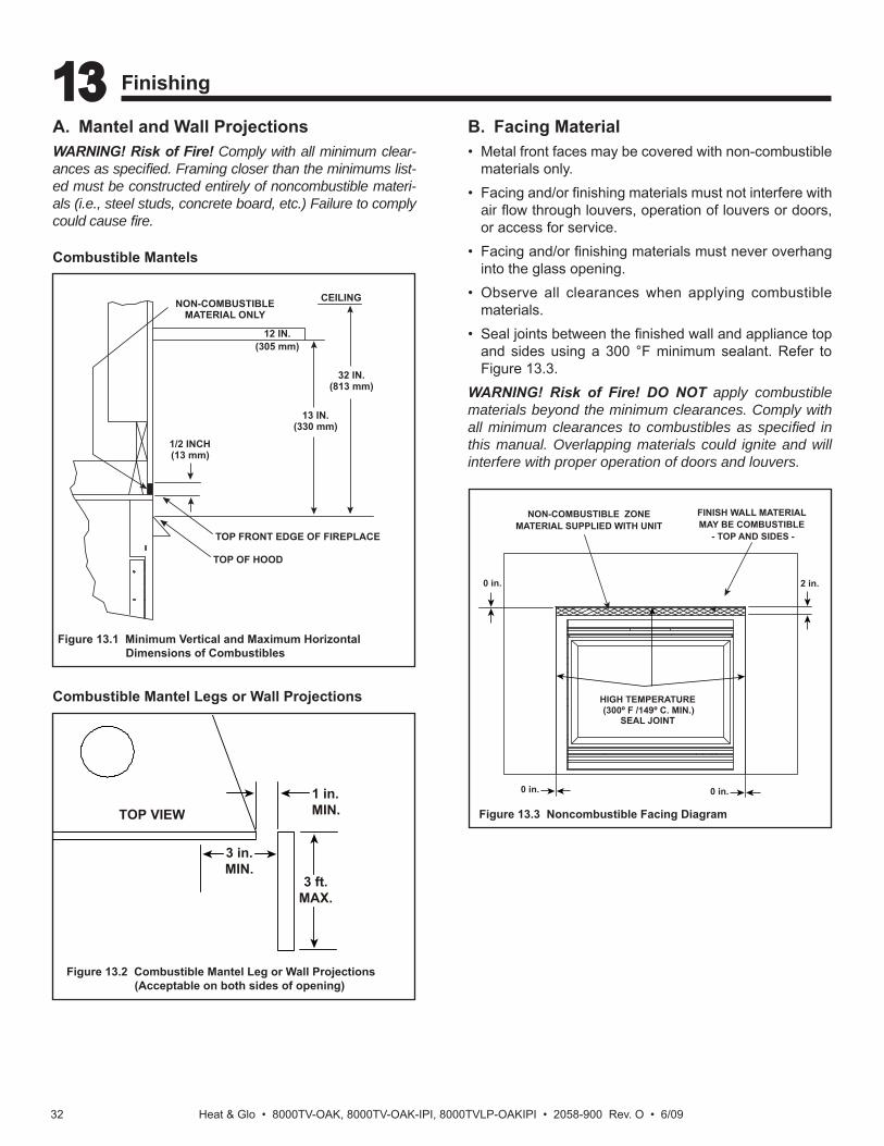
A. Mantel and Wall ProjectionsWARNING! Risk of Fire! Comply with all minimum clear-ances as specifi ed. Framing closer than the minimums list-ed must be constructed entirely of noncombustible materi-als (i.e., steel studs, concrete board, etc.) Failure to comply could cause fi re.
Combustible Mantels
Figure 13.2 Combustible Mantel Leg or Wall Projections (Acceptable on both sides of opening)
Combustible Mantel Legs or Wall Projections
Figure 13.1 Minimum Vertical and Maximum Horizontal Dimensions of Combustibles
B. Facing Material• Metal front faces may be covered with non-combustible
materials only. • Facing and/or fi nishing materials must not interfere with
air fl ow through louvers, operation of louvers or doors, or access for service.
• Facing and/or fi nishing materials must never overhang into the glass opening.
• Observe all clearances when applying combustible materials.
• Seal joints between the fi nished wall and appliance top and sides using a 300 °F minimum sealant. Refer to Figure 13.3.
WARNING! Risk of Fire! DO NOT apply combustible materials beyond the minimum clearances. Comply with all minimum clearances to combustibles as specifi ed in this manual. Overlapping materials could ignite and will interfere with proper operation of doors and louvers.
Figure 13.3 Noncombustible Facing Diagram
1/2 INCH(13 mm)
32 IN.(813 mm)
TOP OF HOOD
12 IN.(305 mm)
NON-COMBUSTIBLEMATERIAL ONLY
13 IN.(330 mm)
CEILING
TOP FRONT EDGE OF FIREPLACE
1 in.MIN.
3 in.MIN.
3 ft.MAX.
TOP VIEW
NON-COMBUSTIBLE ZONEMATERIAL SUPPLIED WITH UNIT
0 in. 0 in.
0 in. 2 in.
HIGH TEMPERATURE(300º F /149º C. MIN.)
SEAL JOINT
FINISH WALL MATERIALMAY BE COMBUSTIBLE
- TOP AND SIDES -
13 Finishing
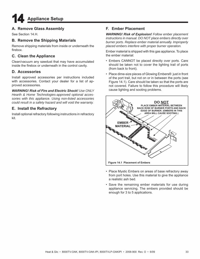
Heat & Glo • 8000TV-OAK, 8000TV-OAK-IPI, 8000TVLP-OAKIPI • 2058-900 Rev. O • 6/09 33
A. Remove Glass AssemblySee Section 14.H.
B. Remove the Shipping MaterialsRemove shipping materials from inside or underneath the fi rebox.
C. Clean the ApplianceClean/vacuum any sawdust that may have accumulated inside the fi rebox or underneath in the control cavity.
D. AccessoriesInstall approved accessories per instructions included with accessories. Contact your dealer for a list of ap-proved accessories.
WARNING! Risk of Fire and Electric Shock! Use ONLY Hearth & Home Technologies-approved optional acces-sories with this appliance. Using non-listed accessories could result in a safety hazard and will void the warranty.
E. Install the RefractoryInstall optional refractory following instructions in refractory kit.
14 Appliance Setup
F. Ember PlacementWARNING! Risk of Explosion! Follow ember placement instructions in manual. DO NOT place embers directly over burner ports. Replace ember material annually. Improperly placed embers interfere with proper burner operation.Ember material is shipped with this gas appliance. To place the ember material:• Embers CANNOT be placed directly over ports. Care
should be taken not to cover the lighting trail of ports (from back to front).
• Place dime-size pieces of Glowing Embers® just in front of the port trail, but not on or in between the ports (see Figure 14.1). Care should be taken so that the ports are not covered. Failure to follow this procedure will likely cause lighting and sooting problems.
Figure 14.1 Placement of Embers
• Place Mystic Embers on areas of base refractory away from port holes. Use this material to give the appliance a realistic ash bed.
• Save the remaining ember materials for use during appliance servicing. The embers provided should be enough for 3 to 5 applications.
EMBERMATERIAL
DO NOTPLACE EMBER MATERIAL BETWEEN
BACK ROW OF BURNER PORTS AND BACKEDGE OF BURNER. (EMBERS IN THIS
AREA WILL CAUSE SOOTING.)
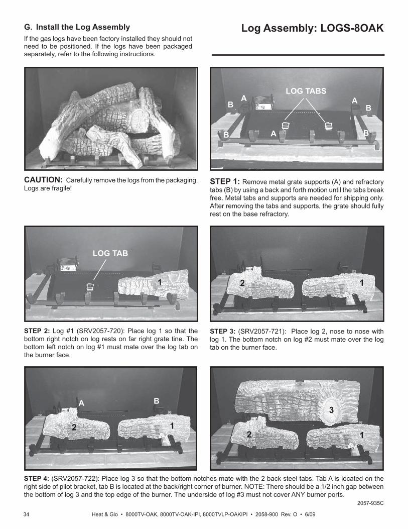
Heat & Glo • 8000TV-OAK, 8000TV-OAK-IPI, 8000TVLP-OAKIPI • 2058-900 Rev. O • 6/0934
G. Install the Log Assembly Log Assembly: LOGS-8OAKIf the gas logs have been factory installed they should not need to be positioned. If the logs have been packaged separately, refer to the following instructions.
CAUTION: Carefully remove the logs from the packaging. Logs are fragile!
STEP 1: Remove metal grate supports (A) and refractory tabs (B) by using a back and forth motion until the tabs break free. Metal tabs and supports are needed for shipping only. After removing the tabs and supports, the grate should fully rest on the base refractory.
STEP 2: Log #1 (SRV2057-720): Place log 1 so that the bottom right notch on log rests on far right grate tine. The bottom left notch on log #1 must mate over the log tab on the burner face.
1
STEP 3: (SRV2057-721): Place log 2, nose to nose with log 1. The bottom notch on log #2 must mate over the log tab on the burner face.
STEP 4: (SRV2057-722): Place log 3 so that the bottom notches mate with the 2 back steel tabs. Tab A is located on the right side of pilot bracket, tab B is located at the back/right corner of burner. NOTE: There should be a 1/2 inch gap between the bottom of log 3 and the top edge of the burner. The underside of log #3 must not cover ANY burner ports.
2 12 1
A
B
21
3A B
A
B
B
A
B
LOG TAB
LOG TABS
2057-935C

Heat & Glo • 8000TV-OAK, 8000TV-OAK-IPI, 8000TVLP-OAKIPI • 2058-900 Rev. O • 6/09 35
STEP 5: (SRV2057-723): Mate the top of log 4 with the right metal tab on log 3. The bottom of log 4 should touch the inside face of the right grate tine.
2
3
1 2
3
1
5 4
2
35
6
STEP 7: (SRV2057-725): Place log 6 on log 2 as shown. The left end of log 6 should touch the upper knot of log 2. The right end of log 6 should rest on the grate bar, centered between tine 4 and 5. NOTE: The front faces (C) of log 6 and 2 should be on the same plane. This is key in avoiding fl ame impingement.
1CC
NOTE: Finished top view.
2
3
1
5 4
6
STEP 6: (SRV2057-724): Notch in left end of Log 5 will interlock with front left corner of grate. Rest right end of log so that it engages tab on log 3. Log 2 may need to shift to right slightly.

Heat & Glo • 8000TV-OAK, 8000TV-OAK-IPI, 8000TVLP-OAKIPI • 2058-900 Rev. O • 6/0936
Figure 14.2 Fixed Glass Assembly
H. Fixed Glass AssemblyRemoving Fixed Glass AssemblyWARNING! Risk of Asphyxiation! Handle fi xed glass assembly with care. Inspect the gasket to ensure it is undamaged and inspect the glass for cracks, chips or scratches.• DO NOT strike, slam or scratch glass.• DO NOT operate fi replace with glass removed, cracked,
broken or scratched.
• Replace as a complete assembly.
Removing Fixed Glass Assembly• Pull the four glass assembly latches out of the groove on
the glass frame. Remove glass door from the appliance (see Figure 14.2).
Replacing Fixed Glass Assembly• Replace the glass door on the appliance. Pull out and
latch the four glass assembly latches into the groove on the glass frame.
I. Install the MeshThe screen mesh is a protective barrier and must be at-tached.
J. Install Trim and/or Surround• Install optional trim kits and/or surrounds using the
instructions included with the accessory.• Use non-combustible materials to cover the gap between
the sheet rock and the appliance (when applicable to the model).
K. Install HoodHood is included with the front and is required in all instal-lations.
GLASSASSEMBLY
LATCHES(BOTH BOTTOM
AND TOP)
L. Shutter Settings
Shutter Settings8000TV-OAK (NG) 1/4 inch8000TV-OAK-IPI (NG) 1/4 inch8000TVLP-OAKIPI Fixed

Heat & Glo • 8000TV-OAK, 8000TV-OAK-IPI, 8000TVLP-OAKIPI • 2058-900 Rev. O • 6/09 37
A. Standing Pilot Ignition System
15 Troubleshooting
With proper installation, operation, and maintenance your gas appliance will provide years of trouble-free service. If you do experience a problem, this troubleshooting guide will assist a qualifi ed service technician in the diagnosis of a problem and the corrective action to be taken. This troubleshooting guide can only be used by a qualifi ed service technician. Contact your dealer to arrange a service call by a qualifi ed service technician.
Symptom Possible Causes Corrective Action1. After repeated triggering
of the red or black piezo ignitor button, the spark ignitor will not light the pilot.
A. No gas or low gas pressure. Check the remote shut-off valves from the appliance. Usually, there is a valve near the gas main. There can be more than one valve be-tween the appliance and the main.
B. No LP in tank. Check the LP (propane) tank. You may be out of fuel.
C. Ignitor. Check the spark at the electrode and pilot. If no spark and electrode wire is properly connected, replace the ignitor. Verify that there is no short in electrode wire.
D. Pilot or misaligned electrode (spark at electrode).
Using match, light the pilot. If the pilot lights, turn off the pilot and trigger the piezo ignitor button again. If the pilot lights, an improper gas/air mixture caused the bad lighting and a longer purge period is recommended. If the pilot will not light, ensure the gap at the elec-trode and pilot is one-eighth in. to have a strong spark. If the gap is OK, replace the pilot.
2. The pilot will not stay lit after carefully following the lighting instructions.
A. Thermocouple. Check that the pilot fl ame impinges on the thermocouple. Adjust the pilot for proper fl ame impingement.
Ensure that the thermocouple connection at the gas valve is fully in-serted and tight (hand tighten plus 1/4 turn).
Verify proper voltage output from the thermocouple to the valve. Place one millivolt meter lead wire on the thermocouple copper lead. Place the second lead wire on the solder button on the back of the valve (blue wire). Start the pilot and hold the valve knob in. The mil-livolt reading should read 8-16 millivolts. If millivolt reading is less than 8 millivolts, replace thermocouple.
B. Improper gas inlet pressure. Natural gas should be 5-14 in. w.c. LP should be 11-14 in. w.c. Verify pressure with manometer.
C. Valve. If the thermocouple is producing 8-16 millivolts, replace control valve.
3. The pilot is burning, there is no burner fl ame, the valve knob is in the ON position, and the ON/OFF switch is in the ON position.
A. On/off switch or wires. Check the ON/OFF switch and wires for proper connections. Place the jumper wires across the terminals at the switch. If the burner comes on, replace the switch. If the switch is OK, place the jumper wires across the switch wires at the gas valve. If the burner comes on, the wires are faulty or connections are bad.
B. Thermopile may not be gen-erating suffi cient millivoltage.
Check that the pilot fl ame impinges thermopile properly.
Be sure the wire connections from the thermopile at the gas valve terminals are tight and that the thermopile is fully inserted into the pilot bracket.
Check the thermopile with a millivolt meter. Take the reading at TH-TP&TP terminals of the gas valve. The meter should read 350 mil-livolts minimum, while holding the valve knob depressed in the pilot position, with the pilot lit, and the ON/OFF switch in the OFF position. Replace the thermopile if the reading is below the specifi ed mini-mum.
With the pilot in the ON position, disconnect the thermopile leads from the valve. Take a reading at the thermopile leads. The reading should be 350 millivolts minimum. Replace the thermopile if the read-ing is below the minimum.

Heat & Glo • 8000TV-OAK, 8000TV-OAK-IPI, 8000TVLP-OAKIPI • 2058-900 Rev. O • 6/0938
Troubleshooting (continued)
Symptom Possible Cause Corrective Action
3. (Continued) C. Back drafting may be tripping the spill switch. Negative pressure, wind or fl ue blockage may be causing spillage. Perform negative pressure diagnos-tics and inspect venting.
D. Valve. Turn the valve knob to the ON position. Place the ON/OFF switch in the ON position. Take a reading with a millivolt meter at the thermopile terminals. The millivolt meter should read greater than 125mV. If the reading is acceptable, and if the burner does not come on, re-place the gas valve.
E. Plugged burner orifi ce. Check the burner orifi ce for stoppage. Remove stop-page.
F. Wall switch or wires. Check the wall switch and wires for proper connec-tions. Place the jumper wires across the terminals at the wall switch. If the burner comes on, replace the wall switch. If the wall switch is OK, place the jumper wires across the wall switch wires at the gas valve. If the burner comes on, the wires are faulty or connec-tions are bad.
4. Frequent pilot outage problem.
A. Pilot fl ame may be too high or too low, or blow-ing out (high pressure), causing pilot safety to drop out.
Clean thermocouple and adjust the pilot fl ame for proper fl ame impingement. Follow lighting instructions carefully.
5. The pilot and main burner extinguish while in operation.
A. No LP in tank. Check the LP (propane) tank. Refi ll the fuel tank.
B. Improper gas inlet pressure. Natural gas should be 5-10 in. w.c. LP should be 10-13 in. w.c. Verify pressure with manometer.
C. Inner vent pipe leaking exhaust gases back into the system.
Check venting system for damage. Replace/repair im-properly assembled pipe sections.
D. Glass installed improperly. Check to ensure glass is installed properly. Replace fi xed glass panel assembly.
E. Thermopile or thermocouple. Replace pilot if necessary.
F. Improper vent cap installation. Check for proper installation and freedom from debris or blockage.
6. Glass soots. A. Flame impingement. Adjust the log set so that the fl ame does not exces-sively impinge on it. Refer to log instructions.
B. Improper air shutter setting. Refer to manual for shutter set points. Ensure that set point is correct for appliance/gas type. If unit has ad-justable shutter, it may be necessary to increase shut-ter opening.
C. Debris around air shutter. Inspect the opening at the base of the burner. NO MA-TERIAL SHOULD BE PLACED IN THIS OPENING.
7. Flame burns blue and lifts off burner.
A. Insuffi cient oxygen being supplied. Ensure that the vent cap is installed properly and free of debris. Ensure that the vent system joints are tight and have no leaks.
Ensure that no debris has been placed at the base of, or in the area of the air holes in the center of the base pan beneath the burner.
Ensure that the glass is tightened properly on the unit, particularly on top corners.
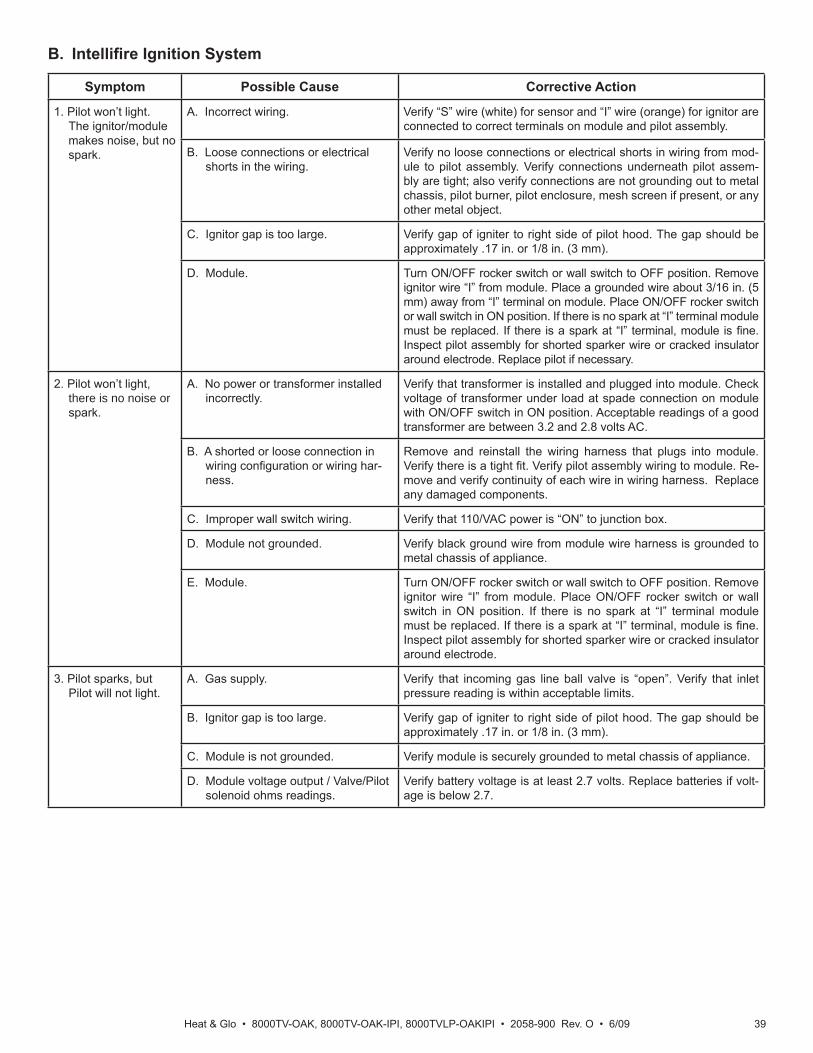
Heat & Glo • 8000TV-OAK, 8000TV-OAK-IPI, 8000TVLP-OAKIPI • 2058-900 Rev. O • 6/09 39
B. Intellifi re Ignition System
Symptom Possible Cause Corrective Action
1. Pilot won’t light. The ignitor/module makes noise, but no spark.
A. Incorrect wiring. Verify “S” wire (white) for sensor and “I” wire (orange) for ignitor are connected to correct terminals on module and pilot assembly.
B. Loose connections or electrical shorts in the wiring.
Verify no loose connections or electrical shorts in wiring from mod-ule to pilot assembly. Verify connections underneath pilot assem-bly are tight; also verify connections are not grounding out to metal chassis, pilot burner, pilot enclosure, mesh screen if present, or any other metal object.
C. Ignitor gap is too large. Verify gap of igniter to right side of pilot hood. The gap should be approximately .17 in. or 1/8 in. (3 mm).
D. Module. Turn ON/OFF rocker switch or wall switch to OFF position. Remove ignitor wire “I” from module. Place a grounded wire about 3/16 in. (5 mm) away from “I” terminal on module. Place ON/OFF rocker switch or wall switch in ON position. If there is no spark at “I” terminal module must be replaced. If there is a spark at “I” terminal, module is fi ne. Inspect pilot assembly for shorted sparker wire or cracked insulator around electrode. Replace pilot if necessary.
2. Pilot won’t light, there is no noise or spark.
A. No power or transformer installed incorrectly.
Verify that transformer is installed and plugged into module. Check voltage of transformer under load at spade connection on module with ON/OFF switch in ON position. Acceptable readings of a good transformer are between 3.2 and 2.8 volts AC.
B. A shorted or loose connection in wiring confi guration or wiring har-ness.
Remove and reinstall the wiring harness that plugs into module. Verify there is a tight fi t. Verify pilot assembly wiring to module. Re-move and verify continuity of each wire in wiring harness. Replace any damaged components.
C. Improper wall switch wiring. Verify that 110/VAC power is “ON” to junction box.
D. Module not grounded. Verify black ground wire from module wire harness is grounded to metal chassis of appliance.
E. Module. Turn ON/OFF rocker switch or wall switch to OFF position. Remove ignitor wire “I” from module. Place ON/OFF rocker switch or wall switch in ON position. If there is no spark at “I” terminal module must be replaced. If there is a spark at “I” terminal, module is fi ne. Inspect pilot assembly for shorted sparker wire or cracked insulator around electrode.
3. Pilot sparks, but Pilot will not light.
A. Gas supply. Verify that incoming gas line ball valve is “open”. Verify that inlet pressure reading is within acceptable limits.
B. Ignitor gap is too large. Verify gap of igniter to right side of pilot hood. The gap should be approximately .17 in. or 1/8 in. (3 mm).
C. Module is not grounded. Verify module is securely grounded to metal chassis of appliance.
D. Module voltage output / Valve/Pilot solenoid ohms readings.
Verify battery voltage is at least 2.7 volts. Replace batteries if volt-age is below 2.7.

Heat & Glo • 8000TV-OAK, 8000TV-OAK-IPI, 8000TVLP-OAKIPI • 2058-900 Rev. O • 6/0940
Intellifi re Ignition System - (continued)
Symptom Possible Cause Corrective Action
4. Pilot lights but contin-ues to spark, and main burner will not ignite. (If the pilot continues to spark after the pilot fl ame has been lit, fl ame rectifi cation has not occurred.)
A. A shorted or loose connection in fl ame sensing rod.
Verify all connections to wiring diagram in manual. Verify connections underneath pilot assembly are tight. Verify con-nections are not grounding out to metal chassis, pilot burn-er, pilot enclosure or screen if present, or any other metal object.
B. Poor fl ame rectifi cation or contaminated fl ame sensing rod.
With fi xed glass assembly in place, verify that fl ame is en-gulfi ng fl ame sensing rod on left side of pilot hood. Flame sensing rod should glow shortly after ignition. Verify cor-rect pilot orifi ce is installed and gas inlet is set to pressure specifi cations. Clean fl ame sensing rod with emery cloth to remove any contaminants that may have accumulated on fl ame sensing rod.
C. Module is not grounded. Verify module is securely grounded to metal chassis of ap-pliance. Verify that wire harness is fi rmly connected to the module.
D. Damaged pilot assembly or contami-nated fl ame sensing rod.
Verify that ceramic insulator around the fl ame sensing rod is not cracked, damaged, or loose. Verify connection from fl ame sensing rod to white sensor wire. Clean fl ame sensing rod with emery cloth to remove any contaminants that may have accumulated on fl ame sensing rod. Verify continuity with a multimeter with ohms set at lowest range. Replace pilot if any damage is detected.
E. Module. Turn ON/OFF rocker switch or wall switch to OFF position. Remove ignitor wire “I” from module. Place ON/OFF rocker switch or wall switch in ON position. If there is no spark at “I” terminal module must be replaced. If there is a spark at “I” terminal, module is fi ne.

Heat & Glo • 8000TV-OAK, 8000TV-OAK-IPI, 8000TVLP-OAKIPI • 2058-900 Rev. O • 6/09 41
16 Reference Materials
A. Appliance Dimension DiagramDimensions are actual appliance dimensions. Use for reference only. For framing dimensions and clearances refer to Section 5.
Figure 16.1 Appliance Dimensions
ELECTRICALACCESS
A
B
C
D
E
F
G
I
GAS LINEACCESS
J
K
L
MO
P
Q
R
H
N
Location Inches MillimetersA 35-1/2 901B 17-3/4 450C 21-1/2 548D 9-1/2 238E 6 151F 40 1015G 9-1/8 233H 2-1/4 56I 33-7/8 859
Location Inches MillimetersJ 23-1/2 598K 39-1/4 996L 43 1091M 48 1221N 7 177O 1-1/8 28P 38-3/4 983Q 2-1/4 58R 5-1/4 134

Heat & Glo • 8000TV-OAK, 8000TV-OAK-IPI, 8000TVLP-OAKIPI • 2058-900 Rev. O • 6/0946
Heat & Glo, a brand of Hearth & Home Technologies Inc. 7571 215th St, Lakeville, MN 55044
www.heatnglo.com
C. Contact Information
Please contact your Heat & Glo dealer with any questions or concerns. For the location of your nearest Heat & Glo dealer,
please visit www.heatnglo.com.
- NOTES -
________________________________________________________________________________
________________________________________________________________________________
________________________________________________________________________________
________________________________________________________________________________
________________________________________________________________________________
________________________________________________________________________________
________________________________________________________________________________
________________________________________________________________________________
________________________________________________________________________________
This product may be covered by one or more of the following patents: (United States) 4593510, 4686807, 4766876, 4793322, 4811534, 5000162, 5016609, 5076254, 5113843, 5191877, 5218953, 5263471, 5328356, 5341794, 5347983, 5429495, 5452708, 5542407, 5601073, 5613487, 5647340,5688568, 5762062, 5775408, 5890485, 5931661, 5941237, 5947112, 5996575, 6006743, 6019099, 6048195, 6053165, 6145502, 6170481, 6237588,6296474, 6374822, 6413079, 6439226, 6484712, 6543698, 6550687, 6601579, 6672860, 6688302B2, 6715724B2, 6729551, 6736133, 6748940,6748942, 6769426, 6774802, 6796302, 6840261, 6848441, 6863064, 6866205, 6869278, 6875012, 6880275, 6908039, 6919884, D320652, D445174,D462436; (Canada) 1297749, 2195264, 2225408, 2313972; (Australia) 780250, 780403, 1418504 or other U.S. and foreign patents pending.
Printed in U.S.A. - Copyright 2009
DO NOT DISCARD THIS MANUAL
NOTICE
• Leave this manual with party responsible for use and operation.
• Important operating and maintenance instructions included.
• Read, understand and follow these instructions for safe installation and operation.