installation and operation instructions ... - penn radiant
TRANSCRIPT

Form 43206000 Sept 2011
INSTALLATION AND OPERATION INSTRUCTIONS
OWNER / INSTALLER: For your safety this manual must be carefully and thoroughly read and understood before installing, operating or servicing this heater.
RSTP SERIES INFRARED RADIANT TUBE HEATER
Single Stage Pull Through System (Negative Pressure)
Models:
RSTP15C RSTP17C
!INSTALLER: This manual is the property of the owner. Please present this manual to the owner when you leave the job site.
▲WARNING: Improper installation, adjustment, alteration, service, or maintenance can cause property damage, injury or death. Read the installation, operation and maintenance instructions thoroughly before installing or servicing this equipment.
IF YOU SMELL GAS: FOR YOUR SAFETYFOR YOUR SAFETYFOR YOUR SAFETYFOR YOUR SAFETY
!!!! DO NOTDO NOTDO NOTDO NOT try to light any appliance.
!!!! DO NOTDO NOTDO NOTDO NOT touch any electrical switch; DO NOTDO NOTDO NOTDO NOT use any telephone in your building.
!!!! IMMEDIATELYIMMEDIATELYIMMEDIATELYIMMEDIATELY call your gas supplier from a neighbor's telephone. Follow the gas supplier's instructions. If you cannot reach your gas supplier, call the fire department.
DO NOT DO NOT DO NOT DO NOT store or use gasoline or other store or use gasoline or other store or use gasoline or other store or use gasoline or other flammable vapors and liquids in the vicinity of flammable vapors and liquids in the vicinity of flammable vapors and liquids in the vicinity of flammable vapors and liquids in the vicinity of this or any other appliance.this or any other appliance.this or any other appliance.this or any other appliance.
!IMPORTANT:!IMPORTANT:!IMPORTANT:!IMPORTANT: SAVE THIS MANUAL FOR FUTURE REFERENCE.SAVE THIS MANUAL FOR FUTURE REFERENCE.SAVE THIS MANUAL FOR FUTURE REFERENCE.SAVE THIS MANUAL FOR FUTURE REFERENCE.
SPACESPACESPACESPACE----RAYRAYRAYRAY Post Office Box 36485 (28236) • 305 Doggett Street (28203) • Charlotte, North Carolina
Phone (704) 372-6391 • Fax (704) 332-5843 • www.spaceray.com • email: [email protected]

Form 43206000 Sept 2011 -1-
TABLE OF CONTENTS
SECTION DESCRIPTION PAGE
1.0) Safety ................................................................................................................................................... 2 2.0) Installer Responsibility ...................................................................................................................... 2 3.0) General Information........................................................................................................................... 2 4.0) Minimum Clearances to Combustibles ........................................................................................... 4 5.0) Specifications...................................................................................................................................... 5 6.0) Packing List ......................................................................................................................................... 5 6.1) Accessory Packages .......................................................................................................................... 5 7.0) Dimensions ......................................................................................................................................... 6 8.0) Heater Assembly Overview ............................................................................................................... 7 9.0) Typical Suspension Methods ............................................................................................................ 8 10.0) Heater Assembly .............................................................................................................................. 10 11.0) Gas Connections and Regulations ................................................................................................. 13 12.0) Instructions for Pressure Test Gauge Connection ....................................................................... 15 13.0) Electrical Connections ..................................................................................................................... 16 14.0) Venting ............................................................................................................................................... 19 15.0) Air for Combustion ........................................................................................................................... 23 15.1) Direct Outside Air for Combustion ................................................................................................. 23 16.0) Lighting and Shutdown Instructions .............................................................................................. 26 17.0) Sequence of Operation .................................................................................................................... 26 18.0) Control Component Location .......................................................................................................... 27 19.0) Cleaning and Annual Maintenance ............................................................................................... 28 20.0) Troubleshooting Guide..................................................................................................................... 29 21.0) Replacing Parts ................................................................................................................................ 32 21.1) Removal of Spark Electrode and Flame Sensor.......................................................................... 32 21.2) Removing Main Burner and Gas Valve ......................................................................................... 33 21.3) Air Switch Pressure Check .............................................................................................................. 33 21.4) Ignition System Checks ................................................................................................................... 34 21.5) Motor and Blower Wheel Check ..................................................................................................... 35 22.0) Installation Data ............................................................................................................................... 35 23.0) Replacement Parts Guide ............................................................................................................... 36
This heater complies with ANSI Z83.20 (current standard) and CSA 2.34. Copies of the National Fuel Gas Code (ANSI Z223.1-latest edition) are available from the CSA at 8501 East Pleasant Valley Road, Cleveland, Ohio 44131 or 55 Scarsdale Road, Don Mills, Ontario M3B 2R3. All NFPA codes are available from the National Fire Protection Association, Batterymarch Park, Quincy, Massachusetts 02269.
Form 43206000 -2- Sept 2011
1.0) SAFETY
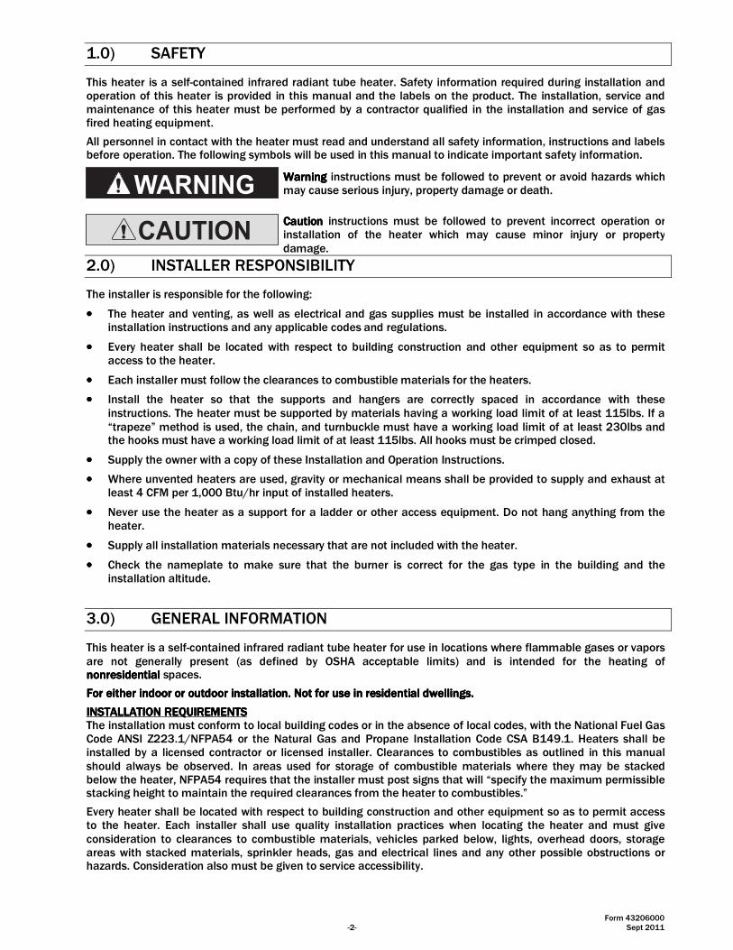
This heater is a self-contained infrared radiant tube heater. Safety information required during installation and operation of this heater is provided in this manual and the labels on the product. The installation, service and maintenance of this heater must be performed by a contractor qualified in the installation and service of gas fired heating equipment.
All personnel in contact with the heater must read and understand all safety information, instructions and labels before operation. The following symbols will be used in this manual to indicate important safety information.
WarningWarningWarningWarning instructions must be followed to prevent or avoid hazards which may cause serious injury, property damage or death.
CautionCautionCautionCaution instructions must be followed to prevent incorrect operation or installation of the heater which may cause minor injury or property damage.
2.0) INSTALLER RESPONSIBILITY
The installer is responsible for the following:
•••• The heater and venting, as well as electrical and gas supplies must be installed in accordance with these installation instructions and any applicable codes and regulations.
•••• Every heater shall be located with respect to building construction and other equipment so as to permit access to the heater.
•••• Each installer must follow the clearances to combustible materials for the heaters.
•••• Install the heater so that the supports and hangers are correctly spaced in accordance with these instructions. The heater must be supported by materials having a working load limit of at least 115lbs. If a “trapeze” method is used, the chain, and turnbuckle must have a working load limit of at least 230lbs and the hooks must have a working load limit of at least 115lbs. All hooks must be crimped closed.
•••• Supply the owner with a copy of these Installation and Operation Instructions.
•••• Where unvented heaters are used, gravity or mechanical means shall be provided to supply and exhaust at least 4 CFM per 1,000 Btu/hr input of installed heaters.
•••• Never use the heater as a support for a ladder or other access equipment. Do not hang anything from the heater.
•••• Supply all installation materials necessary that are not included with the heater.
•••• Check the nameplate to make sure that the burner is correct for the gas type in the building and the installation altitude.
3.0) GENERAL INFORMATION
This heater is a self-contained infrared radiant tube heater for use in locations where flammable gases or vapors are not generally present (as defined by OSHA acceptable limits) and is intended for the heating of nonresidentialnonresidentialnonresidentialnonresidential spaces.
For either indoor or outdoor installaFor either indoor or outdoor installaFor either indoor or outdoor installaFor either indoor or outdoor installation. Not for use in residential dwellings.tion. Not for use in residential dwellings.tion. Not for use in residential dwellings.tion. Not for use in residential dwellings.
INSTALLATION REQUIREMENTSINSTALLATION REQUIREMENTSINSTALLATION REQUIREMENTSINSTALLATION REQUIREMENTS The installation must conform to local building codes or in the absence of local codes, with the National Fuel Gas Code ANSI Z223.1/NFPA54 or the Natural Gas and Propane Installation Code CSA B149.1. Heaters shall be installed by a licensed contractor or licensed installer. Clearances to combustibles as outlined in this manual should always be observed. In areas used for storage of combustible materials where they may be stacked below the heater, NFPA54 requires that the installer must post signs that will “specify the maximum permissible stacking height to maintain the required clearances from the heater to combustibles.”
Every heater shall be located with respect to building construction and other equipment so as to permit access to the heater. Each installer shall use quality installation practices when locating the heater and must give consideration to clearances to combustible materials, vehicles parked below, lights, overhead doors, storage areas with stacked materials, sprinkler heads, gas and electrical lines and any other possible obstructions or hazards. Consideration also must be given to service accessibility.
Form 43206000 Sept 2011 -3-
The heater, when installed in aircraft hangars and public garages, must be installed in accordance with ANSI/NFPA 409-latest edition (Standard for Aircraft Hangars), ANSI/NFPA 88a-latest edition (Standard for Parking Structures), and ANSI/NFPA 88b-latest edition (Standard for Repair Garages) with the following clearances:
a. At least 10 feet above the upper surfaces of wings or engine enclosures of the highest aircraft that may be housed in the hangar and at least 8 feet above the floor in shops, offices, and other sections of hangars communicating with aircraft storage or service areas.
b. At least 8 feet above the floor in public garages. ▲▲▲▲WARNING:WARNING:WARNING:WARNING: Minimum clearances marked on the heater must be maintained from vehicles parked below the heater.
(FOR CANADA ONLY) a. Installation of this appliance is to be in accordance with latest edition of CSA B149.1 (Natural Gas and
Propane Installation Code).
b. For installation in public garages or aircraft hangars, the minimum clearances from the bottom of the infrared heater to the upper surface of the highest aircraft or vehicle shall be 50 percent greater than the certified minimum clearance, but the clearance shall not be less than 8 feet.
Although these heaters may be used in many applications other than space heating (e.g., process heating), Space-Ray will not recognize the warranty for any use other than space heating.
This heater is for Indoor or Outdoor Installation and can be used in either Vented or Unvented mode. The term Unvented actually means Indirect Vented. While the products of combustion are expelled into the building, national codes require ventilation in the building to dilute these products of combustion. This ventilation may be provided by gravity or mechanical means.
This heater is not an explosion proof heater.This heater is not an explosion proof heater.This heater is not an explosion proof heater.This heater is not an explosion proof heater. Where the possibility of exposure to volatile and low flash point materials exists, it could result in property damage or death. This heater must not be installed in a spray booth where the heater can operate during the spraying process. Consult your local fire marshal or insurance company.
High Altitude:High Altitude:High Altitude:High Altitude: Appliances are supplied as standard for altitudes of O to 2,000 feet (0-610 m). High-altitude ratings are obtained by a change in the orifice size. When ordered for high altitude installations, burners are supplied by the factory ready for high altitude installation. Check the nameplate for altitude before proceeding with the installation. In Canada the adjustment for altitude is made in accordance with Standard CGA 2.17, Gas-Fired Appliances for Use at High Altitudes.

Form 43206000 -4- Sept 2011
4.0) MINIMUM CLEARANCES TO COMBUSTIBLES
Failure to do so may result in death, serious injury orproperty damage.
Combustible material must be located outside theclearance dimensions listed.
Minimum clearances to combustibles shall be measured from the outer surfaces as shown in the following diagram:
file: RSTP17C Clearances
60�(152 cm)
*14�(36 cm)
60�(152 cm)
84�(213 cm)
Horizontal
60�(152 cm)
60�(152 cm)
24�(61 cm)
60�(152 cm)
**90 Deg Angle (Max.)
24�(61 cm)
84�(213 cm)
60�(152 cm)
36�(91 cm)
**60 Deg Angle
24�(61 cm)
84�(213 cm)
60�(152 cm)
36�(91 cm)
30 Deg Angle
60�(152 cm)
60�(152 cm)
* Clearance is 30� when installed UNVENTED in Canada.
** Maximum mounting angle is 45 deg when used outdoors.
▲WARNING:▲WARNING:▲WARNING:▲WARNING: Certain materials or objects, when stored under the heater, will be subjected to radiant heat and Certain materials or objects, when stored under the heater, will be subjected to radiant heat and Certain materials or objects, when stored under the heater, will be subjected to radiant heat and Certain materials or objects, when stored under the heater, will be subjected to radiant heat and could be seriously damaged.could be seriously damaged.could be seriously damaged.could be seriously damaged. Observe the Minimum Clearances to Combustibles listed in the manual and on the Observe the Minimum Clearances to Combustibles listed in the manual and on the Observe the Minimum Clearances to Combustibles listed in the manual and on the Observe the Minimum Clearances to Combustibles listed in the manual and on the heater at all times.heater at all times.heater at all times.heater at all times.
NOTE:NOTE:NOTE:NOTE:
1. 1. 1. 1. The clearanThe clearanThe clearanThe clearances specified above must be maintained to combustibles and other materials that may be ces specified above must be maintained to combustibles and other materials that may be ces specified above must be maintained to combustibles and other materials that may be ces specified above must be maintained to combustibles and other materials that may be damaged by temperatures 90ºF above ambient temperature.damaged by temperatures 90ºF above ambient temperature.damaged by temperatures 90ºF above ambient temperature.damaged by temperatures 90ºF above ambient temperature. Clearances to combustibles are posted on the Clearances to combustibles are posted on the Clearances to combustibles are posted on the Clearances to combustibles are posted on the control box.control box.control box.control box. In areas used for storage of combustible materials wherIn areas used for storage of combustible materials wherIn areas used for storage of combustible materials wherIn areas used for storage of combustible materials where they may be stacked below the heater, e they may be stacked below the heater, e they may be stacked below the heater, e they may be stacked below the heater, NFPA54 requires that the installer must post signs that will “specify the maximum permissible stacking height NFPA54 requires that the installer must post signs that will “specify the maximum permissible stacking height NFPA54 requires that the installer must post signs that will “specify the maximum permissible stacking height NFPA54 requires that the installer must post signs that will “specify the maximum permissible stacking height to maintain the required clearances from the heater to combustibles.”to maintain the required clearances from the heater to combustibles.”to maintain the required clearances from the heater to combustibles.”to maintain the required clearances from the heater to combustibles.” SpaceSpaceSpaceSpace----Ray recommends posting these Ray recommends posting these Ray recommends posting these Ray recommends posting these ssssigns adjacent to the heater thermostat or other suitable location that will provide enhanced visibility.igns adjacent to the heater thermostat or other suitable location that will provide enhanced visibility.igns adjacent to the heater thermostat or other suitable location that will provide enhanced visibility.igns adjacent to the heater thermostat or other suitable location that will provide enhanced visibility.
2. The stated clearance to combustibles represents a surface temperature of 902. The stated clearance to combustibles represents a surface temperature of 902. The stated clearance to combustibles represents a surface temperature of 902. The stated clearance to combustibles represents a surface temperature of 90 ºFºFºFºF (32(32(32(32 ºC) above room ºC) above room ºC) above room ºC) above room temperature. Building materials with a low heat totemperature. Building materials with a low heat totemperature. Building materials with a low heat totemperature. Building materials with a low heat tolerance (such as plastics, vinyle siding, canvas, trilerance (such as plastics, vinyle siding, canvas, trilerance (such as plastics, vinyle siding, canvas, trilerance (such as plastics, vinyle siding, canvas, tri----ply, etc.) ply, etc.) ply, etc.) ply, etc.) may be subject to degradation at lower temperatures. It is the installer’s responsibility to assure that adjacent may be subject to degradation at lower temperatures. It is the installer’s responsibility to assure that adjacent may be subject to degradation at lower temperatures. It is the installer’s responsibility to assure that adjacent may be subject to degradation at lower temperatures. It is the installer’s responsibility to assure that adjacent materials are protected from degradation.materials are protected from degradation.materials are protected from degradation.materials are protected from degradation.

Form 43206000 Sept 2011 -5-
5.0) SPECIFICATIONS
Model No.Model No.Model No.Model No. Btu/hrBtu/hrBtu/hrBtu/hr InInInInputputputput
Orifice SizeOrifice SizeOrifice SizeOrifice Size Weight (lbs.)Weight (lbs.)Weight (lbs.)Weight (lbs.) Minimum *Minimum *Minimum *Minimum *
Mounting HeightMounting HeightMounting HeightMounting Height
Natural GasNatural GasNatural GasNatural Gas Propane GasPropane GasPropane GasPropane Gas ShippingShippingShippingShipping UnitUnitUnitUnit @@@@
HorizontalHorizontalHorizontalHorizontal @@@@
45º Angle45º Angle45º Angle45º Angle
RSTP15C-N5D 150,000 #1 (0.220) n/a 256 216 14 ft. 12 ft.
RSTP17C-N5D 175,000 “D” (0.246) n/a 256 216 16 ft. 14 ft.
RSTP17C-L5D 175,000 n/a #26 (0.147) 256 216 16 ft. 14 ft.
* MOUNT HEATERS AS HIGH AS POSSIBLE. Minimums are shown as a guideline for human comfort and uniform energy distribution for complete building heating applications. Consult your Space-Ray representative for the particulars of your installation requirements.
TypeTypeTypeType GasGasGasGas
Gas PipeGas PipeGas PipeGas Pipe Connection Connection Connection Connection
TubeTubeTubeTube DiameterDiameterDiameterDiameter
FlueFlueFlueFlue ConnectionConnectionConnectionConnection
Fresh Air Fresh Air Fresh Air Fresh Air ConnectionConnectionConnectionConnection
ElectricalElectricalElectricalElectrical SupplySupplySupplySupply
CurrentCurrentCurrentCurrent RatingRatingRatingRating
Natural or Propane
½” MPT (Male) 4” 6” Round 6” Round
120 Volt, 60Hz, 1 Phase 2.6 Amp
FuseFuseFuseFuse RRRRating:ating:ating:ating: Ignition System (direct spark):Ignition System (direct spark):Ignition System (direct spark):Ignition System (direct spark):
Spark Module: 3 Amp 250V (for 24V Circuit) 30 second pre-purge period
6.0) PACKING LIST
A.A.A.A. RSTP15C & RSTP17C RSTP15C & RSTP17C RSTP15C & RSTP17C RSTP15C & RSTP17C PackagePackagePackagePackage Part DescriptionPart DescriptionPart DescriptionPart Description QTYQTYQTYQTY Heater Assembly ....................................................................................................................................... 1 Outlet Flue Collar (#42377000)............................................................................................................ 1 Note, Lit. & Parts in Cabinet (#42799000) ......................................................................................... 1 Gas connector, 5/8” OD x 36” (#30302360) ..................................................................................... 1 Installation & Operation Instructions (#43206000) .......................................................................... 1
HEATER ASSEMBLYHEATER ASSEMBLYHEATER ASSEMBLYHEATER ASSEMBLY PACKAGE NUMBPACKAGE NUMBPACKAGE NUMBPACKAGE NUMBERSERSERSERS
NATURAL GASNATURAL GASNATURAL GASNATURAL GAS
PROPANE GASPROPANE GASPROPANE GASPROPANE GAS
MODEL NO. MODEL NO. MODEL NO. MODEL NO. PART NO.PART NO.PART NO.PART NO.
MODEL NO. MODEL NO. MODEL NO. MODEL NO. PART NO.PART NO.PART NO.PART NO.
RSTP15C-N5D #42363011 RSTP17C-L5D #42363020
RSTP17C-N5D #42363010
6.1) ACCESSORY PACKAGES
A.A.A.A. Indoor Unvented Kit, Part #42406000Indoor Unvented Kit, Part #42406000Indoor Unvented Kit, Part #42406000Indoor Unvented Kit, Part #42406000 Contains:
Exhaust Hood, #42401000……QTY–1 #10-24 x 3/8 Screws, #02168010……QTY–2 Form, #42407000……QTY–1
Exhaust HoodExhaust HoodExhaust HoodExhaust Hood
B.B.B.B. Outdoor Kit, Part #42411000Outdoor Kit, Part #42411000Outdoor Kit, Part #42411000Outdoor Kit, Part #42411000 Contains:
Exhaust Hood, #42401000……QTY–1 Inlet Air Hood, #42408000……QTY–1 Foam Strip, #42001040……QTY–1 #10-24 x 3/8 Screws, #02168010……QTY–4 Form, #42412000……QTY–1
Inlet Air HoodInlet Air HoodInlet Air HoodInlet Air Hood
C.C.C.C. “L” Bracket Kit“L” Bracket Kit“L” Bracket Kit“L” Bracket Kit for 90for 90for 90for 90°°°° mountingmountingmountingmounting, Part #42929000, Part #42929000, Part #42929000, Part #42929000 Contains:
“L” Bracket, #42400000……QTY–4
“L” Bracket“L” Bracket“L” Bracket“L” Bracket
Form 43206000 -6- Sept 2011
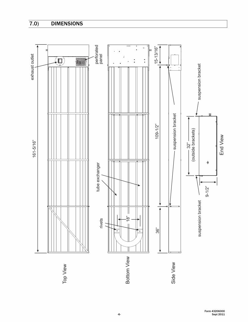
7.0) DIMENSIONS
Top
Vie
w
Bo
tto
m V
iew
18
�
16
1-5
/16
�e
xha
ust
ou
tlet
pe
rfo
rate
dpa
ne
ltu
be
exc
ha
ng
er
Sid
e V
iew
36
�1
09
-1/2
�1
5-1
3/1
6�
susp
en
sio
n b
rack
et
susp
en
sio
n b
rack
et
susp
en
sio
n b
rack
et
32
�(o
uts
ide
bra
cke
ts)
9-1
/2�
En
d V
iew
rive
ts

Form 43206000 Sept 2011 -7-
8.0) HEATER ASSEMBLY OVERVIEW
109-1/2�
suspension chain andturnbuckle rated @230lbs�S� hooks rated @ 115 lbs
long axis of heater
must be level
min.36�
109-1/2�
suspension chain with�S� hooks rated @ 115 lbs 32�
Typically, 2/0 chain, 3/8�eye&eye turnbuckle and #80S hooks meet the capacityrequirements.
Form 43206000 -8- Sept 2011
9.0) TYPICAL SUSPENSION METHODS
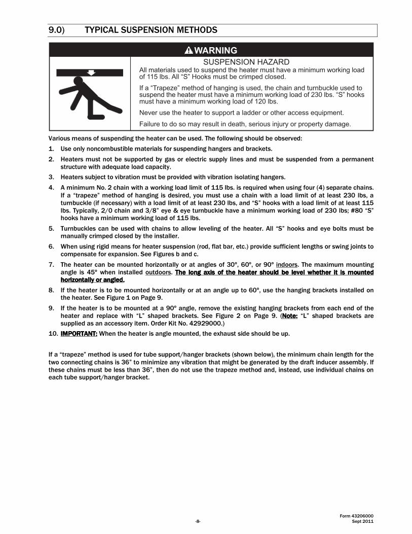
All materials used to suspend the heater must have a minimum working loadof 115 lbs. All �S� Hooks must be crimped closed.
If a �Trapeze� method of hanging is used, the chain and turnbuckle used tosuspend the heater must have a minimum working load of 230 lbs. �S� hooksmust have a minimum working load of 120 lbs.
Never use the heater to support a ladder or other access equipment.
Failure to do so may result in death, serious injury or property damage.
SUSPENSION HAZARD
Various means of suspending the heater can be used. The following should be observed:
1. Use only noncombustible materials for suspending hangers and brackets.
2. Heaters must not be supported by gas or electric supply lines and must be suspended from a permanent structure with adequate load capacity.
3. Heaters subject to vibration must be provided with vibration isolating hangers.
4. A minimum No. 2 chain with a working load limit of 115 lbs. is required when using four (4) separate chains. If a “trapeze” method of hanging is desired, you must use a chain with a load limit of at least 230 lbs, a turnbuckle (if necessary) with a load limit of at least 230 lbs, and “S” hooks with a load limit of at least 115 lbs. Typically, 2/0 chain and 3/8” eye & eye turnbuckle have a minimum working load of 230 lbs; #80 “S” hooks have a minimum working load of 115 lbs.
5. Turnbuckles can be used with chains to allow leveling of the heater. All “S” hooks and eye bolts must be manually crimped closed by the installer.
6. When using rigid means for heater suspension (rod, flat bar, etc.) provide sufficient lengths or swing joints to compensate for expansion. See Figures b and c.
7. The heater can be mounted horizontally or at angles of 30º, 60º, or 90º indoors. The maximum mounting angle is 45º when installed outdoors. The long axis of the heater should be level whether iThe long axis of the heater should be level whether iThe long axis of the heater should be level whether iThe long axis of the heater should be level whether itttt iiiissss mounted mounted mounted mounted horizontally or angled.horizontally or angled.horizontally or angled.horizontally or angled.
8. If the heater is to be mounted horizontally or at an angle up to 60º, use the hanging brackets installed on the heater. See Figure 1 on Page 9.
9. If the heater is to be mounted at a 90º angle, remove the existing hanging brackets from each end of the heater and replace with “L” shaped brackets. See Figure 2 on Page 9. (Note:Note:Note:Note: “L” shaped brackets are supplied as an accessory item. Order Kit No. 42929000.)
10. IMPORTANT:IMPORTANT:IMPORTANT:IMPORTANT: When the heater is angle mounted, the exhaust side should be up.
If a “trapeze” method is used for tube support/hanger brackets (shown below), the minimum chain length for the two connecting chains is 36” to minimize any vibration that might be generated by the draft inducer assembly. If these chains must be less than 36”, then do not use the trapeze method and, instead, use individual chains on each tube support/hanger bracket.

Form 43206000 Sept 2011 -9-
d.
Eyebolt
Turnbuckle*
MinimumNo. 2 Chain*
Eyebolt
c.
ThreadedRod
Turnbuckle
Eyebolt
b.
3/16� x 1� wideFlat Bar
MinimumNo. 2 Chain*
a.
S-Hook*(typical)
Hanger Bracket
* Minimum 2/0 chain, 3/8� eye & eye turnbuckle and #80 �S� hook should be used if a �trapeze� suspension method is desired.
Bracket
Lockwasher
Flat Washer
Cap Screw
Bracket(�L� shaped)
Lockwasher
Flat Washer
Cap Screw
36� (91cm) M
inimum
36� (
91cm
) Min
imum
Figure 1 Figure 2

Form 43206000 -10- Sept 2011
10.0) HEATER ASSEMBLY
Sheet metal parts, particularly reflectors and vent have sharpedges. Always use gloves when handling.
Failure to do so may result in death, serious injury or propertydamage.
CUT HAZARD
The heater is completely factory assembled. The gas manifold tubing requires field assembly; the recommended procedure is as follows:
1. Add the manifold tube and fittings. The required components are packaged inside the control box.
a. Remove the access panel. Apply pipe joint compound to the 5/8” tube x 1/2” Male NPT compression union and screw it into the valve. The pipe joint compound should be resistant to the action of liquefied petroleum gases.
b. Assemble the 5/8” tube x 1/2” Female NPT compression union to the opposite end of the manifold tube, then slide the manifold tube through the hole on control box.
c. Connect the manifold tube to the valve at the compression fitting. When connecting, use a wrench to hold the compression union on the valve.
d. Leak check the gas line up to the gas valve using soap solution method at a pressure of 14” w.c. Replace the access panel.
5/8� Tube x 1/2� Male NPTCompression Fitting
Manifold Tube 5/8� Tube x 1/2� Female NPTCompression Fitting
Note: Components packaged in control box.
ab
c
Pipe Joint
Hold withWrench
Tighten CompressionFittings
Form 43206000 Sept 2011 -11-
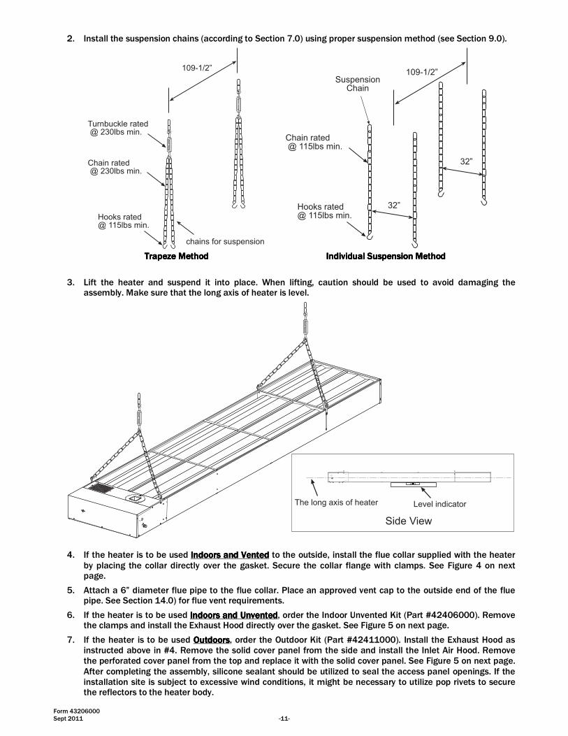
2. Install the suspension chains (according to Section 7.0) using proper suspension method (see Section 9.0).
chains for suspension
109-1/2�
Hooks rated@ 115lbs min.
Turnbuckle rated @ 230lbs min.
Chain rated @ 230lbs min.
109-1/2�Suspension
Chain
32�
32�
Chain rated @ 115lbs min.
Hooks rated@ 115lbs min.
Trapeze MethodTrapeze MethodTrapeze MethodTrapeze Method Individual Suspension MethodIndividual Suspension MethodIndividual Suspension MethodIndividual Suspension Method
3. Lift the heater and suspend it into place. When lifting, caution should be used to avoid damaging the assembly. Make sure that the long axis of heater is level.
Level indicatorThe long axis of heater
Side View
4. If the heater is to be used Indoors and VentedIndoors and VentedIndoors and VentedIndoors and Vented to the outside, install the flue collar supplied with the heater
by placing the collar directly over the gasket. Secure the collar flange with clamps. See Figure 4 on next page.
5. Attach a 6” diameter flue pipe to the flue collar. Place an approved vent cap to the outside end of the flue pipe. See Section 14.0) for flue vent requirements.
6. If the heater is to be used IndoIndoIndoIndoors and Unventedors and Unventedors and Unventedors and Unvented, order the Indoor Unvented Kit (Part #42406000). Remove the clamps and install the Exhaust Hood directly over the gasket. See Figure 5 on next page.
7. If the heater is to be used OutdoorsOutdoorsOutdoorsOutdoors, order the Outdoor Kit (Part #42411000). Install the Exhaust Hood as instructed above in #4. Remove the solid cover panel from the side and install the Inlet Air Hood. Remove the perforated cover panel from the top and replace it with the solid cover panel. See Figure 5 on next page. After completing the assembly, silicone sealant should be utilized to seal the access panel openings. If the installation site is subject to excessive wind conditions, it might be necessary to utilize pop rivets to secure the reflectors to the heater body.

Form 43206000 -12- Sept 2011
NOTE:NOTE:NOTE:NOTE: EXHAUST HOODS ANDEXHAUST HOODS ANDEXHAUST HOODS ANDEXHAUST HOODS AND INLET AIR HOODS ARE SUPPLIED AS ACCESSORY ITEMS. REFER TO THE PART INLET AIR HOODS ARE SUPPLIED AS ACCESSORY ITEMS. REFER TO THE PART INLET AIR HOODS ARE SUPPLIED AS ACCESSORY ITEMS. REFER TO THE PART INLET AIR HOODS ARE SUPPLIED AS ACCESSORY ITEMS. REFER TO THE PART NUMBERS BELOW TO ORDER THE KIT YOUR APPLICATION MAY REQUIRE.NUMBERS BELOW TO ORDER THE KIT YOUR APPLICATION MAY REQUIRE.NUMBERS BELOW TO ORDER THE KIT YOUR APPLICATION MAY REQUIRE.NUMBERS BELOW TO ORDER THE KIT YOUR APPLICATION MAY REQUIRE.
PPPPARTARTARTART NNNNOOOO.... DESCRIPTIONDESCRIPTIONDESCRIPTIONDESCRIPTION
42406000 Indoor Unvented Kit (includes Exhaust Hood)
42411000 Outdoor Kit (includes Exhaust Hood and Inlet Air Hood)
Flue Collar
Clamp
Gasket
PerforatedCover Panelas Fresh Air Inlet(DO NOT obstructopening) Solid Cover
Panel
Access Panel
BurnerSight Glass
Figure 4 Indoor Installation Vented
ExhaustHood(Unvented, Indoor/Outdoorinstallation)
Figure 5
Solid CoverPanel
Inlet Air Hood(Outdoor Installation Only)
Note: When the heater is angle mounted, the exhauster side should be up.Note: When the heater is angle mounted, the exhauster side should be up.Note: When the heater is angle mounted, the exhauster side should be up.Note: When the heater is angle mounted, the exhauster side should be up.
Form 43206000 Sept 2011 -13-
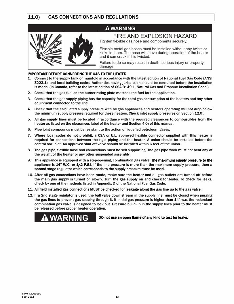
11.0) GAS CONNECTIONS AND REGULATIONS
Tighten flexible gas hose and components securely.
Flexible metal gas hoses must be installed without any twists orkinks in them. The hose will move during operation of the heaterand it can crack if it is twisted.
Failure to do so may result in death, serious injury or propertydamage.
IMPORTANT BEFORE CONNECTING THE GAS TO THE HEATERIMPORTANT BEFORE CONNECTING THE GAS TO THE HEATERIMPORTANT BEFORE CONNECTING THE GAS TO THE HEATERIMPORTANT BEFORE CONNECTING THE GAS TO THE HEATER 1. Connect to the supply tank or manifold in accordance with the latest edition of National Fuel Gas Code (ANSI
Z223.1), and local building codes. Authorities having jurisdiction should be consulted before the installation is made. (In Canada, refer to the latest edition of CSA B149.1, Natural Gas and Propane Installation Code.)
2. Check that the gas fuel on the burner rating plate matches the fuel for the application.
3. Check that the gas supply piping has the capacity for the total gas consumption of the heaters and any other equipment connected to the line.
4. Check that the calculated supply pressure with all gas appliances and heaters operating will not drop below the minimum supply pressure required for these heaters. Check inlet supply pressures on Section 12.0).
5. All gas supply lines must be located in accordance with the required clearances to combustibles from the heater as listed on the clearances label of the heater and Section 4.0) of this manual.
6. Pipe joint compounds must be resistant to the action of liquefied petroleum gases.
7. Where local codes do not prohibit, a CSA or U.L. approved flexible connector supplied with this heater is required for connections between the rigid piping and the heater. A union should be installed before the control box inlet. An approved shut off valve should be installed within 6 feet of the union.
8. The gas pipe, flexible hose and connections must be self supporting. The gas pipe work must not bear any of the weight of the heater or any other suspended assembly.
9. This appliance is equipped with a step-opening, combination gas valve. The maximum supply pressure to the The maximum supply pressure to the The maximum supply pressure to the The maximum supply pressure to the appliance is 14” W.C. or 1/2 P.S.I.appliance is 14” W.C. or 1/2 P.S.I.appliance is 14” W.C. or 1/2 P.S.I.appliance is 14” W.C. or 1/2 P.S.I. If the line pressure is more than the maximum supply pressure, then a second stage regulator which corresponds to the supply pressure must be used.
10. After all gas connections have been made, make sure the heater and all gas outlets are turned off before the main gas supply is turned on slowly. Turn the gas supply on and check for leaks. To check for leaks, check by one of the methods listed in Appendix D of the National Fuel Gas Code.
11. All field installed gas connections MUST be checked for leakage along the gas line up to the gas valve.
12. If a 2nd stage regulator is used, the ball valve down stream in the supply line must be closed when purging the gas lines to prevent gas seeping through it. If initial gas pressure is higher than 14” w.c. the redundant combination gas valve is designed to lock out. Pressure build-up in the supply lines prior to the heater must be released before proper heater operation.
DO DO DO DO notnotnotnot use an open flame of any kind to test for leaks.use an open flame of any kind to test for leaks.use an open flame of any kind to test for leaks.use an open flame of any kind to test for leaks.
Form 43206000 -14- Sept 2011
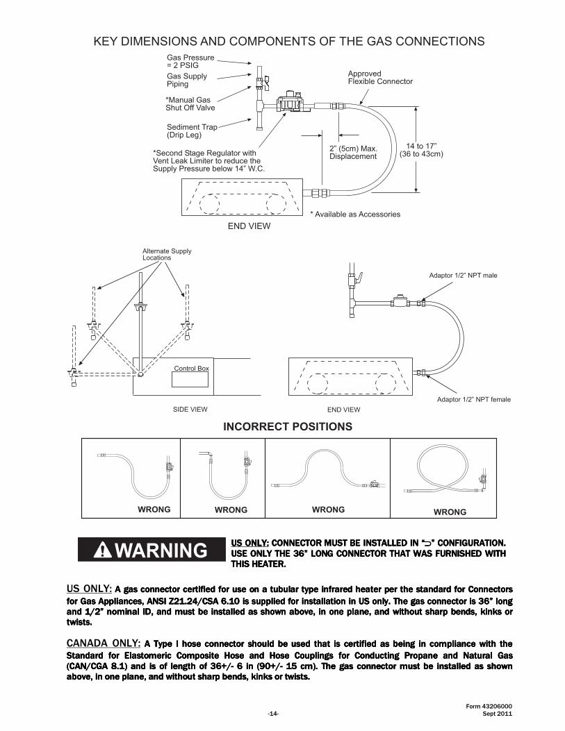
KEY DIMENSIONS AND COMPONENTS OF THE GAS CONNECTIONS
END VIEW
Gas Pressure= 2 PSIG
Gas SupplyPiping
Sediment Trap(Drip Leg)
*Manual GasShut Off Valve
*Second Stage Regulator withVent Leak Limiter to reduce theSupply Pressure below 14� W.C.
* Available as Accessories
14 to 17�(36 to 43cm)
2� (5cm) Max.Displacement
ApprovedFlexible Connector
Adaptor 1/2� NPT female
Adaptor 1/2� NPT male
Alternate SupplyLocations
SIDE VIEW
Control Box
END VIEW
INCORRECT POSITIONS
WRONG WRONG WRONGWRONG
US ONLY:US ONLY:US ONLY:US ONLY: CONNECTOR MUST BE INSTALLED IN “CONNECTOR MUST BE INSTALLED IN “CONNECTOR MUST BE INSTALLED IN “CONNECTOR MUST BE INSTALLED IN “⊃⊃⊃⊃” CONFIGURATION. ” CONFIGURATION. ” CONFIGURATION. ” CONFIGURATION. USE ONLY THE 36” LONG CONNECTOR THAT WAS FURNISHED WITH USE ONLY THE 36” LONG CONNECTOR THAT WAS FURNISHED WITH USE ONLY THE 36” LONG CONNECTOR THAT WAS FURNISHED WITH USE ONLY THE 36” LONG CONNECTOR THAT WAS FURNISHED WITH THIS HEATER.THIS HEATER.THIS HEATER.THIS HEATER.
US ONLY: A gas connector certified for use on a tubular typeA gas connector certified for use on a tubular typeA gas connector certified for use on a tubular typeA gas connector certified for use on a tubular type infrared heater per the standard for Connectors infrared heater per the standard for Connectors infrared heater per the standard for Connectors infrared heater per the standard for Connectors
for Gas Appliances, ANSI Z21.24/CSA 6.10 is supplied for installation in US only. The gas connector is 36” long for Gas Appliances, ANSI Z21.24/CSA 6.10 is supplied for installation in US only. The gas connector is 36” long for Gas Appliances, ANSI Z21.24/CSA 6.10 is supplied for installation in US only. The gas connector is 36” long for Gas Appliances, ANSI Z21.24/CSA 6.10 is supplied for installation in US only. The gas connector is 36” long and and and and 1111////2222” nominal ID, and must be installed as shown above, in” nominal ID, and must be installed as shown above, in” nominal ID, and must be installed as shown above, in” nominal ID, and must be installed as shown above, in one plane, and without sharp bendone plane, and without sharp bendone plane, and without sharp bendone plane, and without sharp bends, kinks or s, kinks or s, kinks or s, kinks or twists.twists.twists.twists.
CANADA ONLY: A Type I hose connector should be used that is certified as being in compliance with the A Type I hose connector should be used that is certified as being in compliance with the A Type I hose connector should be used that is certified as being in compliance with the A Type I hose connector should be used that is certified as being in compliance with the
Standard for Elastomeric Composite Hose and Hose Couplings for Conducting Propane and Natural Gas Standard for Elastomeric Composite Hose and Hose Couplings for Conducting Propane and Natural Gas Standard for Elastomeric Composite Hose and Hose Couplings for Conducting Propane and Natural Gas Standard for Elastomeric Composite Hose and Hose Couplings for Conducting Propane and Natural Gas (CAN/CGA 8.1) and is of length of (CAN/CGA 8.1) and is of length of (CAN/CGA 8.1) and is of length of (CAN/CGA 8.1) and is of length of 36+/36+/36+/36+/---- 6 in (90+/6 in (90+/6 in (90+/6 in (90+/---- 15 cm).15 cm).15 cm).15 cm). The gas connector The gas connector The gas connector The gas connector must be installed as shownmust be installed as shownmust be installed as shownmust be installed as shown aboveaboveaboveabove, in one plane, and without sharp bends, kinks or twists., in one plane, and without sharp bends, kinks or twists., in one plane, and without sharp bends, kinks or twists., in one plane, and without sharp bends, kinks or twists.
Form 43206000 Sept 2011 -15-
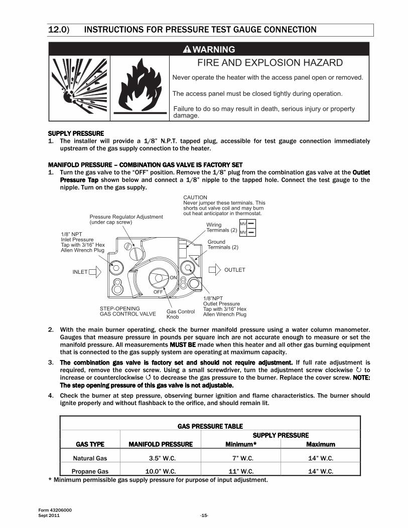
12.0) INSTRUCTIONS FOR PRESSURE TEST GAUGE CONNECTION
Failure to do so may result in death, serious injury or propertydamage.
The access panel must be closed tightly during operation.
Never operate the heater with the access panel open or removed.
SUPPLY PRESSURESUPPLY PRESSURESUPPLY PRESSURESUPPLY PRESSURE 1. The installer will provide a 1/8” N.P.T. tapped plug, accessible for test gauge connection immediately
upstream of the gas supply connection to the heater.
MANIFOLD PRESSURE MANIFOLD PRESSURE MANIFOLD PRESSURE MANIFOLD PRESSURE –––– COMBINATION GAS VALVE IS FACTORY SETCOMBINATION GAS VALVE IS FACTORY SETCOMBINATION GAS VALVE IS FACTORY SETCOMBINATION GAS VALVE IS FACTORY SET 1. Turn the gas valve to the “OFF” position. Remove the 1/8” plug from the combination gas valve at the Outlet Outlet Outlet Outlet
Pressure TPressure TPressure TPressure Tapapapap shown below and connect a 1/8” nipple to the tapped hole. Connect the test gauge to the nipple. Turn on the gas supply.
Pressure Regulator Adjustment(under cap screw)
1/8� NPTInlet PressureTap with 3/16� HexAllen Wrench Plug
1/8�NPTOutlet PressureTap with 3/16� HexAllen Wrench PlugGas Control
Knob
WiringTerminals (2)
GroundTerminals (2)
OUTLETINLET
CAUTIONNever jumper these terminals. Thisshorts out valve coil and may burnout heat anticipator in thermostat.
STEP-OPENINGGAS CONTROL VALVE
ON
OFF
MV
MV
2. With the main burner operating, check the burner manifold pressure using a water column manometer. Gauges that measure pressure in pounds per square inch are not accurate enough to measure or set the manifold pressure. All measurements MUST BEMUST BEMUST BEMUST BE made when this heater and all other gas burning equipment that is connected to the gas supply system are operating at maximum capacity.
3. The combination gas valve is factory set and should not require adjustment.The combination gas valve is factory set and should not require adjustment.The combination gas valve is factory set and should not require adjustment.The combination gas valve is factory set and should not require adjustment. If full rate adjustment is required, remove the cover screw. Using a small screwdriver, turn the adjustment screw clockwise � to increase or counterclockwise � to decrease the gas pressure to the burner. Replace the cover screw. NOTE: NOTE: NOTE: NOTE: The step opening pressure of this gas valve is not adjustable.The step opening pressure of this gas valve is not adjustable.The step opening pressure of this gas valve is not adjustable.The step opening pressure of this gas valve is not adjustable.
4. Check the burner at step pressure, observing burner ignition and flame characteristics. The burner should ignite properly and without flashback to the orifice, and should remain lit.
GAS PRESSURE TABLEGAS PRESSURE TABLEGAS PRESSURE TABLEGAS PRESSURE TABLE
GAS TYPEGAS TYPEGAS TYPEGAS TYPE MANIFOLD PRESSUREMANIFOLD PRESSUREMANIFOLD PRESSUREMANIFOLD PRESSURE
SUPPLY PRESSURESUPPLY PRESSURESUPPLY PRESSURESUPPLY PRESSURE
Minimum*Minimum*Minimum*Minimum* MaximumMaximumMaximumMaximum
Natural Gas 3.5” W.C. 7” W.C. 14” W.C.
Propane Gas 10.0” W.C. 11” W.C. 14” W.C.
* Minimum permissible gas supply pressure for purpose of input adjustment.

Form 43206000 -16- Sept 2011
13.0) ELECTRICAL CONNECTIONS
Failure to do so may result in death or serious injury.
This appliance must be connected to a properly grounded electrical source.
Disconnect electrical power and gas supply before servicing.
ELECTRIC SHOCK HAZARD
1. All electric wiring shall conform to the latest edition of the National Electrical Code (ANSI/NFPA No. 70), or the code legally authorized in the locality where the installation is made.
2. The unit must be electrically grounded in accordance with the National Electrical Code (ANSI/NFPA No. 70-latest edition). In Canada, refer to current standard C22.1 Canadian Electrical Code Part 1.
3. The wiring providing power to the heater shall be connected to a permanently live electrical circuit, one that is not controlled by a light switch.
4. The power supply to the unit should be protected with a fused disconnect switch or circuit breaker. A service switch, as required by local codes, shall be located in the vicinity of the heater (check local codes for allowable distances) and should be identified as Heater Service Switch. All electrical wiring must be located in accordance with the required Clearances to Combustibles from the heater as listed on the nameplate on the heater.
5. When connecting the supply circuitsupply circuitsupply circuitsupply circuit to the heater, wiring material having a minimum size of 14 AWG and a
temperature rating of at least 90°C shall be used.
INTERNAL CONNECTION WIRING DIAGRAM INTERNAL CONNECTION WIRING DIAGRAM INTERNAL CONNECTION WIRING DIAGRAM INTERNAL CONNECTION WIRING DIAGRAM ———— Direct Spark IgnitionDirect Spark IgnitionDirect Spark IgnitionDirect Spark Ignition
FLAMESENSORv
G
BL BL
BKBK
RW
BKBK
RBK
W
BKBK
BKW
DRAFTINDUCERMOTOR
GAS VALVE
AIR SWITCH
25V(GND)
25V GND(BURNER)
VALVE VALVE
TRANSFORMER120V PRIMARY
24V SECONDARY
AG
R
IGNITION MODULE
HIGH VOLTAGECABLE
ELECTRODEGAP 3/16�
CONTINUE TOADDITIONAL
HEATERS
NE
UT
RA
L 12
0V
TH
ER
MO
STA
T
GR
OU
ND
L1
L2
TERMINALBLOCK
FACTORY WIRING
FIELD WIRINGCONTROL CABINETMONITORING LIGHTSCircuit d'origine
Connexions clientLampes témoins
Ne
utr
e
Terr
e
Vers les autresradiateurs
Plaque àbornes
Transformateurbobine primaire 120ÊV
bobine secondaire 24ÊV
pressostat
Robinet à gaz
Écartementd'électrode
4,7Êmm
Haute tension
Armoire de commande
Bloc d'allumage
Moteurd'amorce
d'aspiration
NOTES:NOTES:NOTES:NOTES:
1. If any of the original wire as supplied with the appliance must be replaced, it must be replaced with wiring material having a temperature rating of at least 105ºC. (18 Ga. CSA 600V Type TEW)
2. When connecting the supply circuit to the heater, wiring material having a minimum size of 14 AWG and a temperature rating of at least 90ºC shall be used.
3. A replaceable 3-amp fuse (1-1/4” long) is fitted to the Ignition Control Module.
Form 43206000 Sept 2011 -17-
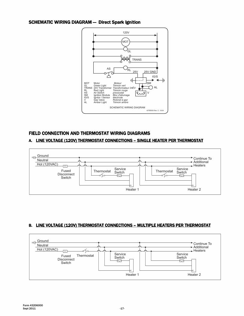
SCHEMATICSCHEMATICSCHEMATICSCHEMATIC WIRING DIAGRAM WIRING DIAGRAM WIRING DIAGRAM WIRING DIAGRAM ———— Direct Spark IgnitionDirect Spark IgnitionDirect Spark IgnitionDirect Spark Ignition
SCHEMATIC WIRING DIAGRAM
MOT Motor MoteurGL Green Light Témoin vertTRANS 24V Transformer Transformateur 24ÊVRL Red Light Témoin rougeAS Air Switch pressostatSM Ignition Module Bloc d'allumageIG/S Ignitor / Sensor électrodeV Gas Valve Robinet à gazAL Amber Light Témoin ambre
MOT
120V
GL
TRANS
RLAS
IG/S
AL
V
SM
42785000 Rev. C 10/04
25V GND25V
FIELD CONNECTION FIELD CONNECTION FIELD CONNECTION FIELD CONNECTION ANANANAND THERMOSTAT D THERMOSTAT D THERMOSTAT D THERMOSTAT WIRING DIAGRAMSWIRING DIAGRAMSWIRING DIAGRAMSWIRING DIAGRAMS
A.A.A.A. LINE VOLTAGE (120V) THERMOSTAT CONNECTIONS LINE VOLTAGE (120V) THERMOSTAT CONNECTIONS LINE VOLTAGE (120V) THERMOSTAT CONNECTIONS LINE VOLTAGE (120V) THERMOSTAT CONNECTIONS –––– SINGLE HEATERSINGLE HEATERSINGLE HEATERSINGLE HEATER PER THERMOSTATPER THERMOSTATPER THERMOSTATPER THERMOSTAT
GroundNeutralHot (120VAC)
FusedDisconnect
Switch
ThermostatServiceSwitch
Heater 1
Continue ToAdditionalHeaters
ThermostatServiceSwitch
Heater 2
B.B.B.B. LINE VOLTAGE (120V) THERMOSTAT CONNECTIONS LINE VOLTAGE (120V) THERMOSTAT CONNECTIONS LINE VOLTAGE (120V) THERMOSTAT CONNECTIONS LINE VOLTAGE (120V) THERMOSTAT CONNECTIONS –––– MULTIPLE HEATERSMULTIPLE HEATERSMULTIPLE HEATERSMULTIPLE HEATERS PER THERMOSTATPER THERMOSTATPER THERMOSTATPER THERMOSTAT
GroundNeutralHot (120VAC)
FusedDisconnect
Switch
Thermostat ServiceSwitch
Heater 1
Continue ToAdditionalHeaters
ServiceSwitch
Heater 2

Form 43206000 -18- Sept 2011
C.C.C.C. LOWLOWLOWLOW VOLTAGE (VOLTAGE (VOLTAGE (VOLTAGE (24242424V) THERMOSTAT CONNECTIONS V) THERMOSTAT CONNECTIONS V) THERMOSTAT CONNECTIONS V) THERMOSTAT CONNECTIONS –––– SINGLE HEATER PESINGLE HEATER PESINGLE HEATER PESINGLE HEATER PER THERMOSTATR THERMOSTATR THERMOSTATR THERMOSTAT
G
BL BL
BKBK
RW
BK
BK
W
BKBK
BK
W
DRAFTINDUCERMOTOR
GAS VALVE
AIR SWITCH
25V(GND)
25V GND(BURNER)
VALVE VALVE
TRANSFORMER120V PRIMARY
24V SECONDARY
A
G
R
IGNITION MODULE
HIGH VOLTAGECABLE
ELECTRODEGAP 3/16�
CONTINUE TOADDITIONAL
HEATERS
NE
UT
RA
L
12
0V
GR
OU
ND
L1
L2
TERMINALBLOCK
FACTORY WIRING
FIELD WIRING
CONTROL CABINET
MONITORING LIGHT
3 4 5
1
LOW VOLTAGETHERMOSTAT (24V)
BK
BK
BK
W
R
FIELD INSTALLEDRELAY KITPART NO.43274000
R
FLAMESENSORv
Order 24V Relay Kit (Part No. 432740Order 24V Relay Kit (Part No. 432740Order 24V Relay Kit (Part No. 432740Order 24V Relay Kit (Part No. 43274000000) for Low Voltage (24V) thermostat connection.0) for Low Voltage (24V) thermostat connection.0) for Low Voltage (24V) thermostat connection.0) for Low Voltage (24V) thermostat connection.
NOTES:NOTES:NOTES:NOTES:
1. If any of the original wire as supplied with the appliance must be replaced, it must be replaced with wiring material having a temperature rating of at least 105ºC. (18 Ga. CSA 600V Type TEW)
2. When connecting the supply circuit to the heater, wiring material having a minimum size of 14 AWG and a temperature rating of at least 90ºC shall be used.
3. A replaceable 3-amp fuse (1-1/4” long) is fitted to the Ignition Control Module.
D.D.D.D. LLLLOWOWOWOW VOLTAGE (VOLTAGE (VOLTAGE (VOLTAGE (24242424V) THERMOSTAT CONNECTIONS V) THERMOSTAT CONNECTIONS V) THERMOSTAT CONNECTIONS V) THERMOSTAT CONNECTIONS –––– MULTIPLE HEATERSMULTIPLE HEATERSMULTIPLE HEATERSMULTIPLE HEATERS PER THERMOSTATPER THERMOSTATPER THERMOSTATPER THERMOSTAT
GroundNeutralHot (120VAC)
FusedDisconnectSwitch
ServiceSwitch
Heater 1
Continue ToAdditionalHeaters
ServiceSwitch
Heater 2
Low VoltageThermostat (24V)
coil
C
R G
NO
Fan Center Relay Part No. 30169000Contact Rating: 120V, 40VA, 12A(maximum of 6 heaters per relay)
Form 43206000 Sept 2011 -19-
14.0) VENTING
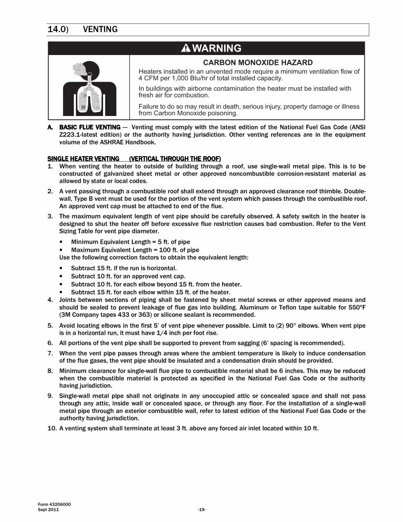
Failure to do so may result in death, serious injury, property damage or illnessfrom Carbon Monoxide poisoning.
Heaters installed in an unvented mode require a minimum ventilation flow of4 CFM per 1,000 Btu/hr of total installed capacity.
In buildings with airborne contamination the heater must be installed withfresh air for combustion.
CARBON MONOXIDE HAZARD
A.A.A.A. BASIC FLUE VENTINGBASIC FLUE VENTINGBASIC FLUE VENTINGBASIC FLUE VENTING — Venting must comply with the latest edition of the National Fuel Gas Code (ANSI Z223.1-latest edition) or the authority having jurisdiction. Other venting references are in the equipment volume of the ASHRAE Handbook.
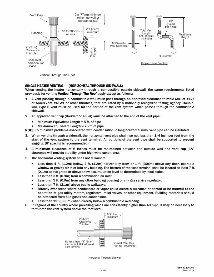
SINGLE HEATER VENTING (VERTICAL THROUGH THE ROOF)SINGLE HEATER VENTING (VERTICAL THROUGH THE ROOF)SINGLE HEATER VENTING (VERTICAL THROUGH THE ROOF)SINGLE HEATER VENTING (VERTICAL THROUGH THE ROOF) 1. When venting the heater to outside of building through a roof, use single-wall metal pipe. This is to be
constructed of galvanized sheet metal or other approved noncombustible corrosion-resistant material as allowed by state or local codes.
2. A vent passing through a combustible roof shall extend through an approved clearance roof thimble. Double-wall, Type B vent must be used for the portion of the vent system which passes through the combustible roof. An approved vent cap must be attached to end of the flue.
3. The maximum equivalent length of vent pipe should be carefully observed. A safety switch in the heater is designed to shut the heater off before excessive flue restriction causes bad combustion. Refer to the Vent Sizing Table for vent pipe diameter.
• Minimum Equivalent Length = 5 ft. of pipe
• Maximum Equivalent Length = 100 ft. of pipe Use the following correction factors to obtain the equivalent length:
• Subtract 15 ft. if the run is horizontal.
• Subtract 10 ft. for an approved vent cap.
• Subtract 10 ft. for each elbow beyond 15 ft. from the heater.
• Subtract 15 ft. for each elbow within 15 ft. of the heater. 4. Joints between sections of piping shall be fastened by sheet metal screws or other approved means and
should be sealed to prevent leakage of flue gas into building. Aluminum or Teflon tape suitable for 550ºF (3M Company tapes 433 or 363) or silicone sealant is recommended.
5. Avoid locating elbows in the first 5’ of vent pipe whenever possible. Limit to (2) 90° elbows. When vent pipe is in a horizontal run, it must have 1/4 inch per foot rise.
6. All portions of the vent pipe shall be supported to prevent from sagging (6’ spacing is recommended).
7. When the vent pipe passes through areas where the ambient temperature is likely to induce condensation of the flue gases, the vent pipe should be insulated and a condensation drain should be provided.
8. Minimum clearance for single-wall flue pipe to combustible material shall be 6 inches. This may be reduced when the combustible material is protected as specified in the National Fuel Gas Code or the authority having jurisdiction.
9. Single-wall metal pipe shall not originate in any unoccupied attic or concealed space and shall not pass through any attic, inside wall or concealed space, or through any floor. For the installation of a single-wall metal pipe through an exterior combustible wall, refer to latest edition of the National Fuel Gas Code or the authority having jurisdiction.
10. A venting system shall terminate at least 3 ft. above any forced air inlet located within 10 ft.
Form 43206000 -20- Sept 2011
Total VentHeight
5 ft (152cm)minimum
6� DiameterVent Connector
Total VentHeight
1/4�(6mm)
per ft rise
Lateral
Single Heater Venting
Vent Cap
Flashing
2� (5cm)ClearanceThimble
Seal Jointand AnnularSpace
10 ft (305cm)or less
2 ft (77cm)minimum
2 ft (77cm) minimum(when no wall orparapet exists)
Wall
or
Para
pet
Vertical Through The Roof
SINGLE HEATER VENTING (HORIZONTAL THROUGH SIDEWALL)SINGLE HEATER VENTING (HORIZONTAL THROUGH SIDEWALL)SINGLE HEATER VENTING (HORIZONTAL THROUGH SIDEWALL)SINGLE HEATER VENTING (HORIZONTAL THROUGH SIDEWALL) When venting the heater horizontally through a combustible outside sidewall, the same requirements listed previously for venting Vertical Through The RoofVertical Through The RoofVertical Through The RoofVertical Through The Roof apply except as follows:
1. A vent passing through a combustible wall must pass through an approved clearance thimble (Air-Jet #4VT or Ameri-Vent #4EWT or other thimbles) that are listed by a nationally recognized testing agency. Double-wall Type B vent must be used for the portion of the vent system which passes through the combustible sidewall.
2. An approved vent cap (Breidert or equal) must be attached to the end of the vent pipe.
• Minimum Equivalent Length = 5 ft. of pipe
• Maximum Equivalent Length = 75 ft. of pipe NOTE:NOTE:NOTE:NOTE: To minimize problems associated with condensation in long horizontal runs, vent pipe can be insulated.
3. When venting through a sidewall, the horizontal vent pipe shall rise not less than 1/4 inch per foot from the start of the vent system to the vent terminal. All portions of the vent pipe shall be supported to prevent sagging. (6’ spacing is recommended)
4. A minimum clearance of 6 inches must be maintained between the outside wall and vent cap (18” clearance will provide stability under high wind conditions).
5. The horizontal venting system shall not terminate:
• Less than 4 ft. (1.2m) below, 4 ft. (1.2m) horizontally from or 1 ft. (30cm) above any door, operable window or gravity air inlet into any building. The bottom of the vent terminal shall be located at least 7 ft. (2.1m) above grade or above snow accumulation level as determined by local codes.
• Less than 3 ft. (0.9m) from a combustion air inlet.
• Less than 3 ft. (0.9m) from any other building opening or any gas service regulator.
• Less than 7 ft. (2.1m) above public walkways.
• Directly over areas where condensate or vapor could create a nuisance or hazard or be harmful to the operation of gas utility meters, regulators, relief valves, or other equipment. Building materials should be protected from flue gases and condensate.
• Less than 12” (0.30m) when directly below a combustible overhang. 6. In regions of the country where prevailing winds are consistently higher than 40 mph, it may be necessary to
terminate the vent system above the roof level.
Sidewall Vent Cap(Part No. 30297040)
2� (5cm)ClearanceThimble
No less than 1/4� (6mm)rise per foot (0.3m) towardvent terminal
6� (15cm)minimum
Horizontal Through Sidewall
Form 43206000 Sept 2011 -21-
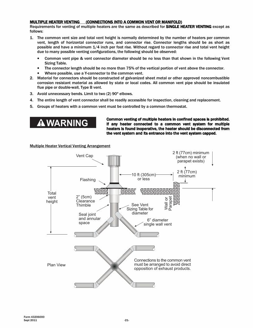
MULTIPLE HEATER VENTING (CONNECTIONS INTO A COMMON VENT OR MANIFOLD)MULTIPLE HEATER VENTING (CONNECTIONS INTO A COMMON VENT OR MANIFOLD)MULTIPLE HEATER VENTING (CONNECTIONS INTO A COMMON VENT OR MANIFOLD)MULTIPLE HEATER VENTING (CONNECTIONS INTO A COMMON VENT OR MANIFOLD) Requirements for venting of multiple heaters are the same as described for SINGLE HEATER VENTINGSINGLE HEATER VENTINGSINGLE HEATER VENTINGSINGLE HEATER VENTING except as follows:
1. The common vent size and total vent height is normally determined by the number of heaters per common vent, length of horizontal connector runs, and connector rise. Connector lengths should be as short as possible and have a minimum 1/4 inch per foot rise. Without regard to connector rise and total vent height due to many possible venting configurations, the following should be observed:
• Common vent pipe & vent connector diameter should be no less than that shown in the following Vent Sizing Table.
• The connector length should be no more than 75% of the vertical portion of vent above the connector.
• Where possible, use a Y-connector to the common vent. 2. Material for connectors should be constructed of galvanized sheet metal or other approved noncombustible
corrosion resistant material as allowed by state or local codes. All common vent pipe should be insulated flue pipe or double-wall, Type B vent.
3. Avoid unnecessary bends. Limit to two (2) 90º elbows.
4. The entire length of vent connector shall be readily accessible for inspection, cleaning and replacement.
5. Groups of heaters with a common vent must be controlled by a common thermostat.
CCCCommon venting of multiple heaters in confined spaces is prohibited. ommon venting of multiple heaters in confined spaces is prohibited. ommon venting of multiple heaters in confined spaces is prohibited. ommon venting of multiple heaters in confined spaces is prohibited. If anIf anIf anIf any heater connected to a common vent system for multiple y heater connected to a common vent system for multiple y heater connected to a common vent system for multiple y heater connected to a common vent system for multiple heaters is found inoperative, the heater should be disconnected from heaters is found inoperative, the heater should be disconnected from heaters is found inoperative, the heater should be disconnected from heaters is found inoperative, the heater should be disconnected from the vent system and its entrance into the vent system capped.the vent system and its entrance into the vent system capped.the vent system and its entrance into the vent system capped.the vent system and its entrance into the vent system capped.
Multiple Heater Vertical Venting Arrangement
Totalvent
height
Vent Cap
Flashing
2� (5cm)ClearanceThimble
Seal jointand annularspace
10 ft (305cm)or less
2 ft (77cm)minimum
2 ft (77cm) minimum(when no wall orparapet exists)
6� diametersingle wall vent
Wall
or
Para
pet
See VentSizing Table for
diameter
Connections to the common ventmust be arranged to avoid directopposition of exhaust products.
Plan View
Form 43206000 -22- Sept 2011
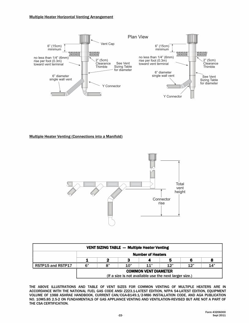
Multiple Heater Horizontal Venting Arrangement
6� diametersingle wall vent
Plan View
Vent Cap
2� (5cm)ClearanceThimble
6� (15cm)minimum
Y Connector
6� diametersingle wall vent
2� (5cm)ClearanceThimble
no less than 1/4� (6mm)rise per foot (0.3m)toward vent terminal
6� (15cm)minimum
Y Connector
See VentSizing Tablefor diameter
See VentSizing Tablefor diameter
no less than 1/4� (6mm)rise per foot (0.3m)toward vent terminal
Multiple Heater Venting (Connections into a Manifold)
Totalvent
height
Connectorrise
VENT SIZING TABLE VENT SIZING TABLE VENT SIZING TABLE VENT SIZING TABLE ———— Multiple Heater VentingMultiple Heater VentingMultiple Heater VentingMultiple Heater Venting
Number of HeatersNumber of HeatersNumber of HeatersNumber of Heaters
1111 2222 3333 4444 5555 6666 8888
RSTP15 and RSTP17 6” 8” 10” 11” 12” 12” 14”
COMMON VENT DIAMETERCOMMON VENT DIAMETERCOMMON VENT DIAMETERCOMMON VENT DIAMETER
(If a size is not available use the next larger size.)
THE ABOVE ILLUSTRATIONS AND TABLE OF VENT SIZES FOR COMMON VENTING OF MULTIPLE HEATERS ARE IN ACCORDANCE WITH THE NATIONAL FUEL GAS CODE ANSI Z223.1-LATEST EDITION, NFPA 54-LATEST EDITION, EQUIPMENT VOLUME OF 1988 ASHRAE HANDBOOK, CURRENT CAN/CGA-B149.1/2-M86 INSTALLATION CODE, AND AGA PUBLICATION NO. 10M5.85 2.5-2 ON FUNDAMENTALS OF GAS APPLIANCE VENTING AND VENTILATION-REVISED BUT ARE NOT A PART OF THE CSA CERTIFICATION.
Form 43206000 Sept 2011 -23-
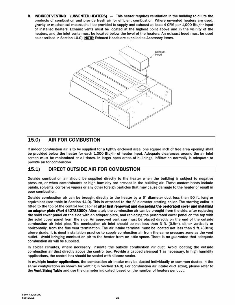
B.B.B.B. INDIRECT VENTING (UNVENTED HEINDIRECT VENTING (UNVENTED HEINDIRECT VENTING (UNVENTED HEINDIRECT VENTING (UNVENTED HEATERS)ATERS)ATERS)ATERS) — This heater requires ventilation in the building to dilute the products of combustion and provide fresh air for efficient combustion. Where unvented heaters are used, gravity or mechanical means shall be provided to supply and exhaust at least 4 CFM per 1,000 Btu/hr input of installed heaters. Exhaust vents must be located at the highest point above and in the vicinity of the heaters, and the inlet vents must be located below the level of the heaters. An exhaust hood must be used as described in Section 10.0). NOTE:NOTE:NOTE:NOTE: Exhaust Hoods are supplied as Accessory items.
ExhaustHood
15.0) AIR FOR COMBUSTION
If indoor combustion air is to be supplied for a tightly enclosed area, one square inch of free area opening shall be provided below the heater for each 1,000 Btu/hr of heater input. Adequate clearances around the air inlet screen must be maintained at all times. In larger open areas of buildings, infiltration normally is adequate to provide air for combustion.
15.1) DIRECT OUTSIDE AIR FOR COMBUSTION
Outside combustion air should be supplied directly to the heater when the building is subject to negative pressure, or when contaminants or high humidity are present in the building air. These contaminants include paints, solvents, corrosive vapors or any other foreign particles that may cause damage to the heater or result in poor combustion.
Outside combustion air can be brought directly to the heater by a 6” diameter duct less than 50 ft. long or equivalent (see table in Section 14.0). This is attached to the 6” diameter starting collar. The starting collar is fitted to the top of the control box cabinet after first removing and discarding the perforated coverafter first removing and discarding the perforated coverafter first removing and discarding the perforated coverafter first removing and discarding the perforated cover and installing and installing and installing and installing an adapter plate (Part #42783000)an adapter plate (Part #42783000)an adapter plate (Part #42783000)an adapter plate (Part #42783000). Alternately the combustion air can be brought from the side, after replacing the solid cover panel on the side with an adapter plate, and replacing the perforated cover panel on the top with the solid cover panel from the side. An approved vent cap must be placed directly on the end of the outside combustion air inlet pipe. The combustion air inlet should be not less than 3 ft. (0.9m), either vertically or horizontally, from the flue vent termination. The air intake terminal must be located not less than 1 ft. (30cm) above grade. It is good installation practice to supply combustion air from the same pressure zone as the vent outlet. Avoid bringing combustion air to the heater from an attic space. There is no guarantee that adequate combustion air will be supplied.
In colder climates, where necessary, insulate the outside combustion air duct. Avoid locating the outside combustion air duct directly above the control box. Provide a capped cleanout T as necessary. In high humidity applications, the control box should be sealed with silicone sealer.
In multiple heater applicationsmultiple heater applicationsmultiple heater applicationsmultiple heater applications, the combustion air intake may be ducted individually or common ducted in the same configuration as shown for venting in Section 14.0). For combustion air intake duct sizing, please refer to the Vent Sizing TableVent Sizing TableVent Sizing TableVent Sizing Table and use the diameter indicated, based on the number of heaters per duct.
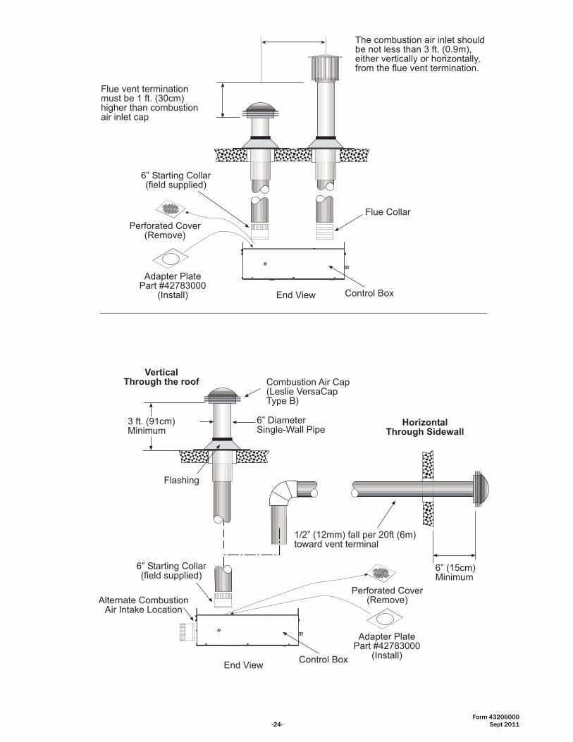
Form 43206000 -24- Sept 2011
Flue vent terminationmust be 1 ft. (30cm)higher than combustionair inlet cap
Perforated Cover(Remove)
Control Box
The combustion air inlet shouldbe not less than 3 ft. (0.9m),either vertically or horizontally,from the flue vent termination.
Adapter PlatePart #42783000
(Install) End View
6� Starting Collar(field supplied)
Flue Collar
Combustion Air Cap(Leslie VersaCapType B)
6� DiameterSingle-Wall Pipe
Flashing
1/2� (12mm) fall per 20ft (6m)toward vent terminal
HorizontalThrough Sidewall
6� (15cm)Minimum
6� Starting Collar(field supplied)
3 ft. (91cm)Minimum
VerticalThrough the roof
Control Box
Perforated Cover(Remove)
Adapter PlatePart #42783000
(Install)End View
Alternate CombustionAir Intake Location

Form 43206000 Sept 2011 -25-
To bring outside combustion air to the heater, you will need to order the RSTP Fresh Air Kit (Part #427820RSTP Fresh Air Kit (Part #427820RSTP Fresh Air Kit (Part #427820RSTP Fresh Air Kit (Part #42782000000)0)0)0), which includes one adapter plate. Refer to installation instruction below.
INSTALLATION INSTRUCTIONS INSTALLATION INSTRUCTIONS INSTALLATION INSTRUCTIONS INSTALLATION INSTRUCTIONS -------- RSTP FRESH AIR KIT RSTP FRESH AIR KIT RSTP FRESH AIR KIT RSTP FRESH AIR KIT -------- Part #42782000Part #42782000Part #42782000Part #42782000
1. Remove the existing perforated panel from the top of the heater and replace it with the adapter plate from the Fresh Air Kit.
2. Insert a 6” starting collar (field supplied) and bend over the tabs to secure. Install the 6” diameter duct (not supplied) and vent cap per guidelines above.
Perforated Panel(remove)
InstallAdapter Plate(Part #42783000)
6� Starting Collar for connectionto combustion air duct.(field supplied)
Flue Outlet
Solid Cover Plate
Top Installation
Perforated Panel(remove)
InstallAdapter Plate(Part #42783000)
6� Starting Collar forconnection to combustion air duct.(field supplied)
Flue Outlet
InstallSolid Cover Plate
Side Installation
Form 43206000 -26- Sept 2011
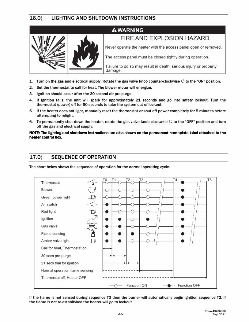
16.0) LIGHTING AND SHUTDOWN INSTRUCTIONS
Failure to do so may result in death, serious injury or propertydamage.
The access panel must be closed tightly during operation.
Never operate the heater with the access panel open or removed.
1. Turn on the gas and electrical supply. Rotate the gas valve knob counter-clockwise � to the “ON” position.
2. Set the thermostat to call for heat. The blower motor will energize.
3. Ignition should occur after the 30-second air pre-purge.
4. If ignition fails, the unit will spark for approximately 21 seconds and go into safety lockout. Turn the thermostat (power) off for 60 seconds to take the system out of lockout.
5. If the heater does not light, manually reset the thermostat or shut off power completely for 5 minutes before attempting to relight.
6. To permanently shut down the heater, rotate the gas valve knob clockwise � to the “OFF” position and turn off the gas and electrical supply.
NOTE: NOTE: NOTE: NOTE: The lighting and shutdown instructions are also shown on the permanent nameplate label attached to the The lighting and shutdown instructions are also shown on the permanent nameplate label attached to the The lighting and shutdown instructions are also shown on the permanent nameplate label attached to the The lighting and shutdown instructions are also shown on the permanent nameplate label attached to the heater control box.heater control box.heater control box.heater control box.
17.0) SEQUENCE OF OPERATION
The chart below shows the sequence of operation for the normal operating cycle.
T0 T1 T2 T3 T4
Call for heat, Thermostat on
Thermostat
Blower
Red light
Ignition
Air switch
Gas valve
Flame sensing
Amber valve light
Function ON Function OFF
Green power light
30 secs pre-purge
21 secs trial for ignition
Normal operation flame sensing
Thermostat off, Heater OFF
T5
If the flame is not sensed during sequence T3 then the burner will automatically begin ignition sequence T2. If the flame is not re-established the heater will go to lockout.

Form 43206000 Sept 2011 -27-
18.0) CONTROL COMPONENT LOCATION
1 Cabinet Assembly
2 Air Inlet Plate
3 Access Panel
4 Sight Glass
5 Flame Sensor
6 Ignition Module
7 Ignition Cable (partially shown)
8 Flue Outlet
9 Draft Inducer
10 Manifold Tubing
11 Terminal Block and Shield
12 Transformer (120/24 VAC)
13 Monitoring Light, Green
14 Monitoring Light, Red
15 Monitoring Light, Amber
16 Gas Valve
17 Nipple
18 Nipple and Plug
19 Entrance Cone & Support Assembly
20 Main Burner
21 Spark Electrode
22 Air Switch
23 Air Sensing Probe
10
1
2
4
131415
3
1816
5 6 78
9
1112
19
2021
2223
17
Form 43206000 -28- Sept 2011
19.0) CLEANING AND ANNUAL MAINTENANCE
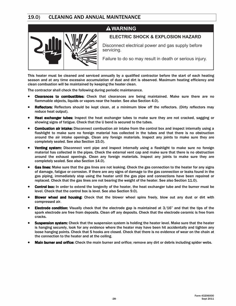
ELECTRIC SHOCK & EXPLOSION HAZARD
Disconnect electrical power and gas supply beforeservicing.
Failure to do so may result in death or serious injury.
This heater must be cleaned and serviced annually by a qualified contractor before the start of each heating season and at any time excessive accumulation of dust and dirt is observed. Maximum heating efficiency and clean combustion will be maintained by keeping the heater clean.
The contractor shall check the following during periodic maintenance.
•••• Clearances to combustibles:Clearances to combustibles:Clearances to combustibles:Clearances to combustibles: Check that clearances are being maintained. Make sure there are no flammable objects, liquids or vapors near the heater. See also Section 4.0).
•••• Reflectors:Reflectors:Reflectors:Reflectors: Reflectors should be kept clean, at a minimum blow off the reflectors. (Dirty reflectors may reduce heat output).
•••• Heat exchanger tubes:Heat exchanger tubes:Heat exchanger tubes:Heat exchanger tubes: Inspect the heat exchanger tubes to make sure they are not cracked, sagging or showing signs of fatigue. Check that the U bend is secured to the tubes.
•••• Combustion air intake:Combustion air intake:Combustion air intake:Combustion air intake: Disconnect combustion air intake from the control box and inspect internally using a flashlight to make sure no foreign material has collected in the tubes and that there is no obstruction around the air intake openings. Clean any foreign materials. Inspect any joints to make sure they are completely sealed. See also Section 15.0).
•••• Venting Venting Venting Venting ssssystem:ystem:ystem:ystem: Disconnect vent pipe and inspect internally using a flashlight to make sure no foreign material has collected in the pipes. Check the external vent cap and make sure that there is no obstruction around the exhaust openings. Clean any foreign materials. Inspect any joints to make sure they are completely sealed. See also Section 14.0).
•••• Gas lines:Gas lines:Gas lines:Gas lines: Make sure that the gas lines are not leaking. Check the gas connection to the heater for any signs of damage, fatigue or corrosion. If there are any signs of damage to the gas connection or leaks found in the gas piping, immediately stop using the heater until the gas pipe and connections have been repaired or replaced. Check that the gas lines are not bearing the weight of the heater. See also Section 11.0).
•••• ControlControlControlControl bbbbox:ox:ox:ox: In order to extend the longevity of the heater, the heat exchanger tube and the burner must be level. Check that the control box is level. See also Section 9.0).
•••• Blower wheel and housing:Blower wheel and housing:Blower wheel and housing:Blower wheel and housing: Check that the blower wheel spins freely, blow out any dust or dirt with compressed air.
•••• Electrode condition:Electrode condition:Electrode condition:Electrode condition: Visually check that the electrode gap is maintained at 3/16” and that the tips of the spark electrode are free from deposits. Clean off any deposits. Check that the electrode ceramic is free from cracks.
•••• Suspension system:Suspension system:Suspension system:Suspension system: Check that the suspension system is holding the heater level. Make sure that the heater is hanging securely, look for any evidence where the heater may have been hit accidentally and tighten any loose hanging points. Check that S hooks are closed. Check that there is no evidence of wear on the chain at the connection to the heater and at the ceiling.
•••• Main Main Main Main bbbburner and urner and urner and urner and oooorifice:rifice:rifice:rifice: Check the main burner and orifice; remove any dirt or debris including spider webs.

Form 43206000 Sept 2011 -29-
20.0) TROUBLESHOOTING GUIDE
T
urn
on li
ne v
olta
ge
and
ther
mos
tat.
Doe
sth
e g
reen m
onito
ring
light co
me o
n in
the
contr
ol c
abin
et?
Yes
No
Is there
120V
betw
een the L
1 a
nd
L2 term
inals
on the
term
inal b
lock
in the
contr
ol c
abin
et?
Yes
No
Are
the b
lack
lead
wires
of th
e g
reen
light se
cure
ly o
n the
term
inals
? No
Yes
Repla
ce the g
reen
light.
Repa
ir c
onnect
ion.
Check
line v
olta
ge a
tth
erm
ost
at and li
ne
volta
ge c
urcu
it. R
epai
rfa
ult.
Is the d
raft
induce
ron?
Yes
No
Are
the le
ad w
ires
of
the d
raft
induce
rse
cure
ly o
n the
term
inals
L1 a
nd L
2in
the
cont
rol c
abin
et?
No
Yes
Repa
ir c
onnect
ion.
Is 1
20V
on
one
of th
ete
rmin
als
of th
e le
ad
wires
of th
e d
raft
induce
r m
oto
r?
Does
the r
ed
mon
itorin
g lig
ht c
ome
on in
the c
ontr
ol
cabin
et?
Yes
No
Is there
24 v
ac
betw
een term
inals
of
the
tran
sfor
mer
on
the
seco
ndar
y si
de in
the
contr
ol c
abin
et?
Yes
No
Check
the term
inal
blo
ck for
contin
uity
;re
pla
ce it
if n
oco
ntin
uity
.
Repa
ir c
onnect
ions.
Is the a
ir h
ose
secu
rely
con
nect
ed to
the
air
switc
h an
d th
eair s
ensi
ng tubin
g a
tth
e d
raft
induce
r?
No
Cle
an o
ut hose
and
pro
be.
Tro
uble
shootin
gco
ntin
ued
on th
e ne
xtpa
ge.
No
Yes
Check
term
inal b
lock
for c
ontin
uity
. Rep
lace
it if
no c
ontin
uity
.
Dis
conn
ect t
he p
ower
and
chec
k m
otor
lead
wires.
Any
wire
bro
ken?
Yes
No
Repa
ir b
roke
n w
ires.
Check
the b
low
er
wheel.
Does
it tu
rnfr
eely
?
Yes
Repla
ce m
oto
r
Check
blo
wer
wheel.
Is th
ere
any
dam
age?
Repla
ce b
low
er
wheel.
Readju
st b
low
er
wheel o
n s
haft
&re
tighte
n s
et cr
ew
.
Che
ck th
e ai
r se
nsin
gtu
be a
nd h
ose
. Are
they
clear
and
unobst
ruct
ed?
Che
ck th
e pr
essu
re a
tth
e a
ir s
witc
h. Is
ithig
her
than the
min
imum
required?
Is the r
ed w
ire fro
mtr
ansf
orm
er
secu
rely
connect
ed to a
irsw
itch term
inal C
?
Move
the r
ed w
ire to
air s
witc
h term
inal C
.
Is o
ne w
ire o
f the r
ed
light co
nnect
ed to a
irsw
itch term
inal N
O?
No
Yes
Repla
ce tra
nsf
orm
er.
Are
the b
lack
and
white
wires
to the
transf
orm
er
secu
rely
on the term
inals
?
No
Yes
Repa
ir c
onnect
ion.
No
No
Yes
No
No
Check
the v
olta
ge
betw
een a
ir s
witc
hte
rmin
al C
and
gro
und, is
it 2
4 v
ac?
Yes
Is th
ere1
20 v
ac o
n th
eprim
ary
sid
e o
f th
etr
ansf
orm
er?
Yes
No
When the d
raft
induce
r is
runnin
g, is
ther
e 24
vac
bet
wee
nai
r sw
itch
term
inal
NO
and g
round ?
No
Move
the w
ire to a
irsw
itch term
inal N
O.
Is th
e ot
her w
ire o
f the
red
light
con
nect
ed to
the te
rmin
al c
om
mon
of tr
ansf
orm
er?
No
Yes
Connect
this
wire o
fth
e r
ed li
ght to
the
transf
orm
er
term
inal
com
mon a
long w
ithth
e w
hite
wire fro
mig
niti
on m
odule
.
Yes
Yes
No
Yes
Yes
Check
the r
ed w
ire
from
tra
nsf
orm
er
for
contin
uity
.R
epla
ce it
if n
oco
ntin
uity
.
Yes
Repla
ce the a
irsw
itch.
No
Check
the a
ir in
take
and v
ent. A
re there
any
blo
ckages?
Yes
No
Rem
ove
blo
ckage.
Rest
art
trouble
shootin
g.
Che
ck v
ent a
nd fr
esh
air le
ngth
s. A
re they
with
in the m
axi
mum
perm
issi
ble
?
No
Yes
Reduce
them
with
inth
e m
axi
mum
perm
issi
ble
.
Rem
ove
the b
low
er.
Is th
e w
heel
free
from
dirt and d
ust
?
Cle
an the b
low
er
wheel.
Rest
art
trouble
shootin
g.
No
Yes
Does
the b
low
er
turn
freely
?N
o
Yes
Repla
ce the d
raft
induce
r ass
em
bly
.
Check
the r
est
rict
or
pla
te s
tam
ped ID
. Is
it co
rrect
for
the
heate
r?N
o
Yes
Rep
lace
the
rest
ricto
rpla
te.
Conta
ct fact
ory
for
ass
ista
nce
.
Repla
ce the r
ed
monito
ring li
ght.

Form 43206000 -30- Sept 2011
30 s
eco
nds
afte
rst
art
up, does
the
ambe
r mon
itorin
g lig
htco
me
on in
the
cont
rol
cabin
et?
Yes
No
while
the a
mber
light
is o
n, th
rough the
insp
ect
ion w
indow
, is
ther
e a
flam
e vi
sibl
e?Y
es
No
Is th
e kn
ob o
n th
e ga
sva
lve in
the O
Npo
sitio
n? (
It�s
ship
ped
from
the fact
ory
at
OF
F p
osi
tion)
Yes
No
Is th
ere
24 v
ac a
cros
s25V
(GN
D)
and 2
5V
term
inals
on ig
niti
on
module
?
Repla
ce the a
mber
light.
Are
the tw
o w
ires
toth
e a
mber
light
secu
rely
hooke
d to
the term
inals
of th
egas
valv
e?
Does
the a
mber
light
stay
on u
ntil
call
for
heat ends? Yes
No
Repa
ir c
onnect
ion.
Tro
uble
shootin
gco
ntin
ued
on th
e ne
xtpa
ge.
Move
the r
ed w
ire to
air s
witc
h term
inal
NO
.
Is the r
ed w
ire fro
mig
niti
on m
odule
25V
term
inal
con
nect
ed to
air s
witc
h term
inal
NO
?
Rest
art
trouble
shootin
g.
Yes
No
Turn
the k
nob to O
Nposi
tion.
No
30 s
eco
nds
afte
rst
art
up, ch
eck
the
volta
ge a
cross
valv
ete
rmin
als
on ig
niti
on
module
. Is
it 2
4 v
ac?
No
Yes
Is the fuse
OK
on
igniti
on m
odule
?
Yes
No
Repla
ce the fuse
.
Yes
Is there
a s
park
acr
oss
ignite
r gap?
Yes
No
Is the g
round w
irin
gbetw
een the ig
niti
on
module
and the
contr
ol b
ox
OK
?
No
Yes
Adju
st the fla
me
senso
r tip
into
the
flam
e.
Is the c
era
mic
insu
lato
r O
K o
n the
spark
ele
ctro
de?
No
Yes
Repla
ce the s
park
ele
ctro
de.
Is the s
park
gap
3/1
6�?
No
Yes
Adju
st the s
park
gap
to 3
/16�.
Repla
ce the ig
niti
on
module
& ig
niti
on
cable
.
Spa
rk s
tops
when
burn
er
is li
t?
Yes
No
Is th
e fla
me
sens
or ti
pdirect
ly in
the fla
me?
No
Yes
Repla
ce the ig
niti
on
module
.Is
there
contin
uity
betw
een
flam
e se
nsor
and
grou
nd s
tud
in th
eca
bin
et?
No
Repla
ce the fla
me
senso
r.
Tro
uble
shootin
gco
ntin
ued fro
m the
pre
vious
page.
Fix
the g
roundin
gpro
ble
m.
Repla
ce the ig
niti
on
module
.
Yes
No
Is th
e w
hite
wire
from
igniti
on m
odule
25V
(GN
D)
conn
ecte
dto
the tra
nsf
orm
er
term
inal c
om
mon
secu
rely
?
Yes
No
Yes
Check
the fla
me
curr
ent a
t the ig
niti
on
module
. Is
it o
ver
1.5
mA
with
fla
me?
No
Yes
Repla
ce ig
niti
on
module
.
See n
ext
page for
trouble
shootin
gse
quence
.
Rest
art
trouble
shootin
g.
Move
the w
hite
wire
to the tra
nsf
orm
er
term
inal c
om
mon.

Form 43206000 Sept 2011 -31-
Cal
l for
hea
t end
s an
dth
e h
eate
r sh
uts
off?
Yes
No
Trou
bles
hoot
ing
ends
.
Therm
ost
at is
not
work
ing p
roperly.
Repla
ce it
ifnece
ssary
.
Is the g
reen li
ght st
illon?
Yes
No
Turn
off
gas
&ele
ctrici
tyim
media
tely
.R
epla
ce the g
as
valv
e.
Rem
ove
valv
e le
ad a
tig
nitio
n m
odul
e. D
oes
valv
e c
lose
?
No
Yes
Rech
eck
therm
ost
at
and w
irin
g.
Tro
uble
shootin
gco
ntin
ued fro
m the
pre
vious
page.
Tro
uble
shootin
gco
ntin
ued fro
m the
pre
vious
page.
Che
ck th
e sp
ark
gap.
Is it
3/1
6�? N
o
Yes
Adju
st the s
park
gap
to 3
/16�.
Has
all
the a
ir b
een
purg
ed fro
m the g
as
supply
lines?
No
Yes
Pur
ge th
e ga
s su
pply
line.
Check
the in
let
pre
ssure
to the g
as
valv
e. Is
it b
etw
een
min
imum
and
maxi
mum
for
the g
as
type?
No
Yes
Adju
st s
upply
gas
pre
ssure
.R
est
art
trouble
shootin
g.
Check
the m
anifo
ldgas
pre
ssure
during
start
up. Is
it z
ero
inch
es?
Yes
No
Repla
ce g
as
valv
e.
Afte
r an in
itial s
tep
openin
g, is
the
man
ifold
gas
pre
ssur
eco
rrect
?
No
Yes
Adju
st m
anifo
ld g
as
pre
ssure
. R
est
art
trouble
shootin
g.
Call
fact
ory
for
ass
ista
nce
.C
heck
orific
e a
nd
hold
er
for
blo
ckage
(i.e
. sp
ider
web).
Is
there
any
blo
ckage?
Yes
No
Cle
ar
blo
ckage.

Form 43206000 -32- Sept 2011
21.0) REPLACING PARTS
ELECTRIC SHOCK & EXPLOSION HAZARD
Disconnect electrical power and gas supply beforeservicing.
Failure to do so may result in death or serious injury.
Only use genuine Space-Ray replacement parts. Parts are available from the factory for replacement by a licensed person. Refer to the Replacement Parts Guide in Section 23.0) for all replacement parts.
21.1) REMOVAL OF SPARK ELECTRODE AND FLAME SENSOR
1
2
2
3/16�
3
4
5
Spark ElectrodeFlame Sensor
1. Disconnect electrical supply, open access panel.
2. Remove two mounting screws for each and take out the spark electrode and flame sensor.
3. Check that the spark gap is 3/16”.
4. Check spark electrode and flame sensor. The rods should be clean and free from debris.
5. Check ceramic on the spark electrode and flame sensor. It should be free from cracks.
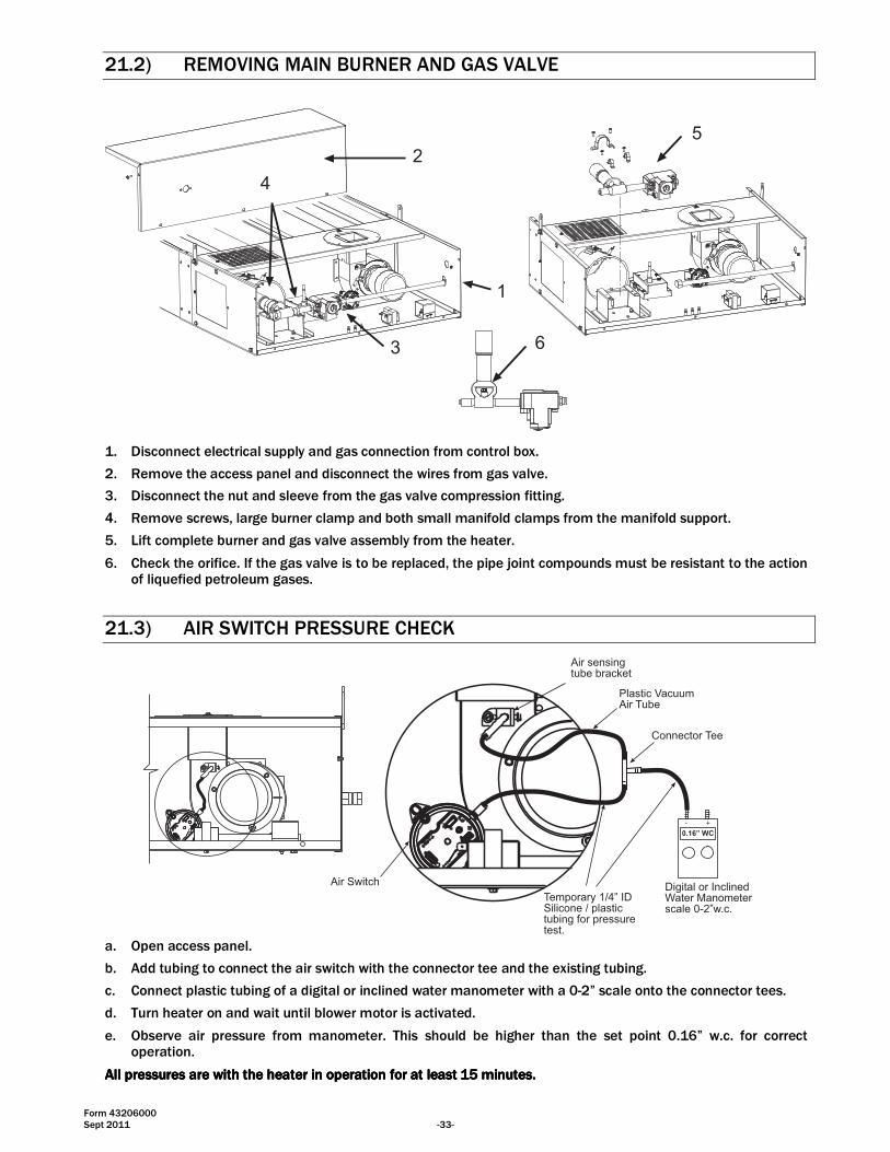
Form 43206000 Sept 2011 -33-
21.2) REMOVING MAIN BURNER AND GAS VALVE
3
4
5
6
1
2
1. Disconnect electrical supply and gas connection from control box.
2. Remove the access panel and disconnect the wires from gas valve.
3. Disconnect the nut and sleeve from the gas valve compression fitting.
4. Remove screws, large burner clamp and both small manifold clamps from the manifold support.
5. Lift complete burner and gas valve assembly from the heater.
6. Check the orifice. If the gas valve is to be replaced, the pipe joint compounds must be resistant to the action of liquefied petroleum gases.
21.3) AIR SWITCH PRESSURE CHECK
Temporary 1/4� IDSilicone / plastictubing for pressuretest.
Air Switch
Plastic VacuumAir Tube
0.16� WC
+-
Air sensingtube bracket
Connector Tee
Digital or InclinedWater Manometerscale 0-2�w.c.
a. Open access panel.
b. Add tubing to connect the air switch with the connector tee and the existing tubing.
c. Connect plastic tubing of a digital or inclined water manometer with a 0-2” scale onto the connector tees.
d. Turn heater on and wait until blower motor is activated.
e. Observe air pressure from manometer. This should be higher than the set point 0.16” w.c. for correct operation.
All pressures are with the heater in operation for at least 15 minutes.All pressures are with the heater in operation for at least 15 minutes.All pressures are with the heater in operation for at least 15 minutes.All pressures are with the heater in operation for at least 15 minutes.

Form 43206000 -34- Sept 2011
21.4) IGNITION SYSTEM CHECKS
TO CHECK TO CHECK TO CHECK TO CHECK IGNITION CABLEIGNITION CABLEIGNITION CABLEIGNITION CABLE.... a. Make sure that the ignition cable does not touch any metal surface.
b. Make sure that connections to the stud terminal and the igniter/sensor are clean and tight.
c. Make sure that the ignition cable provides good electrical continuity.
TO CHECK TO CHECK TO CHECK TO CHECK IGNITION SYSTEM GROUNDINGIGNITION SYSTEM GROUNDINGIGNITION SYSTEM GROUNDINGIGNITION SYSTEM GROUNDING.... (Nuisance shutdowns are often caused by a poor or erratic ground.) A common ground is required for the module, igniter, flame sensor and main burner. a. Check for good metal-to-metal contact between the igniter bracket and the main burner.
b. Check the ground lead from the GND (BURNER) terminal on the module to the igniter bracket. Make sure connections are clean and tight. If the wire is damaged or deteriorated, replace it.
c. Replace igniter/sensor with factory replacement part if insulator is cracked.
TO CHECK TO CHECK TO CHECK TO CHECK SPARK IGNITION CIRCUITSPARK IGNITION CIRCUITSPARK IGNITION CIRCUITSPARK IGNITION CIRCUIT.... ▲WARNING:▲WARNING:▲WARNING:▲WARNING: The ignition circuit generates a 20,000 Volt open circuit and electrical shock can result. a. Check ignition cable.
b. Check external fuse on the module.
c. Verify power (24V) at module input terminals and output terminal to gas valve.
d. Replace spark module if fuse and power are OK.
TO CHECK FLAME SENSOR CIRCUIT.TO CHECK FLAME SENSOR CIRCUIT.TO CHECK FLAME SENSOR CIRCUIT.TO CHECK FLAME SENSOR CIRCUIT. a. Turn off heater at thermostat.
b. Connect a meter (dc microammeter scale) in series with the ground lead as shown in the diagram. Connect the meter as follows:
• Disconnect the ground lead at the electronic control.
• Connect the black (negative) meter lead to the electronic control GND terminal.
• Connect the red (positive) meter lead to the free end of the ground lead. c. Restart the system and read the meter. The flame sensor current must be steady and measure at least 1.5
microamps.
d. If the meter reads less than the minimum or if reading is unsteady:
• Make sure burner flame is capable of providing a good rectification signal.
• Make sure fasteners securing igniter/sensor are tightened to assure correct positions. DO NOTDO NOTDO NOTDO NOT relocate igniter/sensor.
• Check for excessive (over 1000ºF) temperature at ceramic insulator on flame sensor. Excessive temperature can cause short to ground. DO NOTDO NOTDO NOTDO NOT relocate igniter/sensor.
• Check for cracked ceramic insulator, which can cause short to ground, and replace sensor if necessary.
• Make sure that electrical connections are clean and tight. Replace damaged wire. e. If the meter reads below “0” on the scale, meter leads are reversed. Disconnect power and reconnect meter
leads for proper polarity.
f. Remove microammeter. Return system to normal operation.

Form 43206000 Sept 2011 -35-
VALVE
VALVE
(GND)
25V (GND)
25V X
Module
MultipurposeMeter
Red (+)
Black (-)
FLAME SENSOR CURRENT CHECK- use microamp scale -
21.5) MOTOR AND BLOWER WHEEL CHECK
If draft inducer motor fails to run:
a. Check power supply to junction box.
b. Check for loose or broken motor lead wire.
c. Check to see that blower wheel turns freely and is not rubbing housing. Blower wheel may have worked loose from shaft and jammed against housing.
d. Check for blower wheel damage; replace if necessary. If no damage, readjust blower wheel on shaft & retighten set screw.
e. If all above does not correct, replace motor.
22.0) INSTALLATION DATA
Date of Installation:
# of Heaters in System:
Serial No.
Model: RSTPRSTPRSTPRSTP N = Natural Gas L = Propane Gas

Form 43206000 -36- Sept 2011
23.0) REPLACEMENT PARTS GUIDE
CONTROL COMPONENTSCONTROL COMPONENTSCONTROL COMPONENTSCONTROL COMPONENTS
Item No.Item No.Item No.Item No. Part No.Part No.Part No.Part No. DescriptionDescriptionDescriptionDescription
1 30314120 Ignition Cable Assembly
2 30216000 Spark Electrode - #PSE-GF2
3 03763000 Flame Sensor - #PSE-GF3
4 42387000 Entrance Cone & Support Assembly
5 04702000 Clamp, Manifold
6 42393000 Clamp, Burner
7 30175000 Brass Nipple - 1/2
8 41971000 Burner Assembly
9 03339020 Plug - 1/8
10 03259010 Main Burner Orifice (#1) Nat. (RSTP15C-N5D)
11 03259950 Main Burner Orifice ("D") Nat. (RSTP17C-N5D)
12 03259260 Main Burner Orifice (#26) LP (RSTP17C-L5D)
13 03333140 Nipple - 1/2 x 4"
14 30333030 Gas Valve - VR8205A-2008 @ 3-1/2"WC Nat.
15 30333040 Gas Valve - VR8205A-2081 @ 10"WC LP
16 03602100 Compression Union - 5/8 Tube x 1/2 NPT
17 03600040 Compression Sleeve - 5/8 Tube
18 03601040 Compression Nut - 5/8 Tube
19 42372000 Manifold Tubing
20 30244000 Compression Fitting - 5/8 Tube x 1/2 NPT
21 43143000 Draft Inducer Assembly (w/Air Switch)
22 43142000 Draft Inducer Housing Assembly
23 03723000 Blower Wheel
24 43221000 Motor Gasket
25 30347000 Motor Spacer - 5/16"OD x 1"
26 42740000 Motor Plate
27 03721000 Motor - 115V 1/20HP 1.73A 60Hz
28 03988070 Tubing, Silicone - 7"
29 30186201 Air Switch #NS2-0307-00 set @ -.11"WC ORANGE
30 42744020 Air Sensing Tube
31 42742000 Air Sensing Tube Clamp
32 42377000 Flue Collar - Outlet
33 42851000 Vent Collar Assembly
34 42392000 Clamp - Flue Collar
35 42395000 Gasket - Flue Collar
36 42391000 Extrusion Bracket
37 42365000 Control Mounting Panel
38 42368000 Extension Panel - RH
39 42369000 Extension Panel - LH
40 42374000 Cover Panel - Perforated
41 42389000 Cover Panel - Solid
42 42448000 Access Panel Assembly
43 42929000 Suspension Bracket - "L" Shaped
44 40481000 Suspension Bracket - 3"
45 42376000 Flue Collar - Inlet (5/8" dia. holes)
46 30356040 Spark Module - #S87K-1032
47 42398020 Monitoring Light - Green
48 42398070 Monitoring Light - Red
49 42398030 Monitoring Light - Amber
50 42709000 Terminal Block Shield
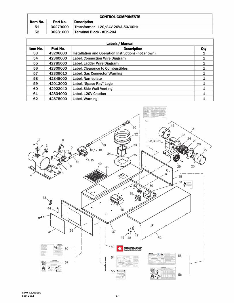
Form 43206000 Sept 2011 -37-
CONTROL COMPONENTSCONTROL COMPONENTSCONTROL COMPONENTSCONTROL COMPONENTS
Item No.Item No.Item No.Item No. Part No.Part No.Part No.Part No. DescriptionDescriptionDescriptionDescription
51 30279000 Transformer - 120/24V 20VA 50/60Hz
52 30281000 Terminal Block - #EK-204
Labels / ManualLabels / ManualLabels / ManualLabels / Manual
Item No.Item No.Item No.Item No. Part No.Part No.Part No.Part No. DescriptionDescriptionDescriptionDescription QtQtQtQty.y.y.y.
53 43206000 Installation and Operation Instructions (not shown) 1
54 42360000 Label, Connection Wire Diagram 1
55 42785000 Label, Ladder Wire Diagram 1
56 42309000 Label, Clearance to Combustibles 1
57 42309010 Label, Gas Connector Warning 1
58 42848000 Label, Nameplate 1
59 42013000 Label, “Space-Ray” Logo 1
60 42922040 Label, Side Wall Venting 1
61 42834000 Label, 120V Caution 1
62 42875000 Label, Warning 1
1
2 3
4
5
6
78
9
10,11,12
1314,15
16,17,18
19
20
5
43
44
41 39
40
32
33
3534
45
2224
2326
27
25
28,30,31
29
21
62
52 50
51
46
37
4249 4847
36
59
WIRE LEGEND
ENGLISH FRANCAISBK BLACK NOIRW WHITE BLANCR RED ROUGEBL BLUE BLEUG GREEN VERTV VIOLET VIOLETA AMBER AMBRE
42706000 Rev. G 1/05
G
BL BL
BKBK
RW
BKBK
RBK
W
BKBK
BK W
DRAFTINDUCERMOTOR
GAS VALVE
AIR SWITCH
25V(GND)
25V GND(BURNER)
VALVE VALVE
TRANSFORMER120V PRIMARY
24V SECONDARY
AG
R
IGNITION MODULE
HIGH VOLTAGECABLE
ELECTRODEGAP 3/16�
CONTINUE TOADDITIONAL
HEATERS
NE
UT
RA
L 12
0V
TH
ER
MO
STA
T
GR
OU
ND
L1
L2
TERMINALBLOCK
FACTORY WIRING
FIELD WIRING
CONNECTION WIRING DIAGRAM
CONTROL CABINET
If any of the original wire as suppliedwith the appliance must be replaced.It must be replaced with wiring materialhaving a temperature rating of at least105oC. (18 AWG. - UL / CSA 600VType TEW)
When connecting the supply circuit tothe heater, wiring material having aminimum size of 14 AWG and atemperature rating of at least 90oCshall be used.
MONITORING LIGHTS
Schéma de circuit de connexion
Circuit d'origine
Connexions clientLampes témoins
Ne
utr
e
Terr
e
Vers les autresradiateurs
Plaque àbornes
Transformateurbobine primaire 120ÊV
bobine secondaire 24ÊV
pressostat
Robinet à gaz
Écartementd'électrode
4,7Êmm
Haute tension
Armoire de commande
Bloc d'allumage
Moteurd'amorce
d'aspiration
S'il faut remplacer un fil de l'appareild'origine, utiliser exclusivement des fils à température de service nominaled'au moins 105C (18 AWG. - UL / CSA600ÊVType TEW).
Pour raccorder le circuit d'alimentationau radiateur, utiliser des fils de calibre14 AWG ou plus à température deservice nominale d'au moins 90C.
SCHEMATIC WIRING DIAGRAM
MOT Motor MoteurGL Green Light Témoin vertTRANS 24V Transformer Transformateur 24ÊVRL Red Light Témoin rougeAS Air Switch pressostatSM Ignition Module Bloc d'allumageIG/S Ignitor / Sensor électrodeV Gas Valve Robinet à gazAL Amber Light Témoin ambre
MOT
120V
GL
TRANS
RLAS
IG/S
AL
V
SM
42785000 Rev. C 10/04
25V GND25V
54
55
60
57Alternate SupplyLocations
TYPICAL GASCONNECTIONEND VIEW
Movement
14 - 17�(356 - 432mm)
Control Box
SIDE VIEW
Flexible Connector
Optional Second Stage Regulator withVent Leak Limiter if required to reducethe Supply Pressure below 14� W.C. Recommended Gas
Pressure 2 PSIG
Gas SupplyPiping
Sediment Trap(Drip Leg)
43344050 Rev. C 3/09
Install the gas flexible hose as shown in the diagram below:
Sharp bends, kinks, twists and tension in the hose may cause failure resulting in a gasleak.
Failure to follow these instructions may result in death, serious injury or property damage.
Note: When venting a singleheater horizontally through acombustible outside wall thevent must pass through a 2�clearance thimble (Air Jet No.4VT or Ameri-vent No 4EWTfor the 40 � 75,000 BTUheaters and Air-Jet No 6VT orAmeri-Vent No. 6EWT for the80 � 250,000 Btu heaters) orother thimbles which are listedby nationally recognized testingagency.
Attach a vent cap (Breidert No.4L or equivalent for the 40-75,000 BTU heaters or BreidertNo. 6L or equivalent for 80 �250,000 BTU heaters) to theend of the pipe.
Minimum equivalent length ofvent pipe = 5ft (1.5m)Maximum equivalent length ofvent pipe = 75ft (23m)
THIS UNIT EQUIPPED WITH A2 AMP IN LINE-FUSE FOROVERCURRENT PROTECTIONOF CONTROL CIRCUIT
ELECTRIC SHOCKHAZARD
Disconnect electrical supplybefore servicingFailure to follow theseinstructions may result indeath, serious injury orproperty damage.
WARNING
DRAFT INDUCER SERIAL NUMBER
42922020 Rev C 8/05
SIDEWALL VENTING ONLY UN MUR LATÉRAL A É R AT I O N
ELECTRICAL SHOCKHAZARD
DISCONNECT POWERBEFORE OPENING COVER
CAUTION
120 VOLTS
42834000
61
WARNING: Improperinstallation, adjustment,alteration, service ormaintenance can causeproperty damage, injuryor death. Read theInstallation, Operatingand MaintenanceInstruction thoroughlybefore servicing thisequipment.
AVERTISSEMENT: Uneinstallation, un réglage, unemodification, une réparationou un entretien incorrect peutentraîner des dommagesmatérials, des blessures oula mort. Lisez attentivementles instructions d�installation,de fonctionnement etd�entretien avant de procéderà l�installation ou à l�entretiende cet équipment.
WARNING: If notinstalled, operated andmaintained in accordancewith the manufacturer�sinstructions, this productcould expose you tosubstances in fuel or fromfuel combustion which cancause death or seriousillness and which areknown to the State ofCalifornia to cause cancer,birth defects or otherreproductive harm. WARNING: This product
contains a chemical knownto the state of California tocause cancer.
This heater can beinstalled in variousconfigurations as shownin the heater layoutsection of the instructions 42875000 Rev. E 10/04
38
58
56
Combustible material must be located outside the clearance dimensions listed.
Ceiling Clearance is 12� (30cm) when installed in an UNVENTED configuration. Ceilingclearance is 18� (46cm) when the optional corner reflectors are not used on ETS or LTS.
Failure to do so may result in death, serious injury or property damageModels LTS/LTU/ETS/ETU
43344000 Rev. B 10/04
Le dégagement au-dessus de l'appareil doit être d'au moins 30 cm quand l'appareil est installéSANS ÉCHAPPEMENT. Le dégagement au-dessus de l'appareil doit être d'au moins 46cmquand les réflecteurs d'angle optionnels ne sont pas utilisés sur l'ETS ou le LTS.
DD
Dessous, 6m du brûleurBelow 20ft from burner
C*20ft (6m)
Model No A B C D E F C*40,50 27� 6� 40� 30� 48� 12� -
(69cm) (15cm) (104cm) (76cm) (122cm) (30cm)60,75 27� 6� 60� 30� 48� 12� -
(69cm) (15cm) (145cm) (76cm) (122cm) (30cm)80,90 52� 6� 84� 30� 52� 12� 72�
(132cm) (15cm) (145cm) (76cm) (122cm) (30cm) (183cm)100 66� 6� 88� 40� 66� 20� 72�
(168cm) (15cm) (224cm) (102cm) (168cm) (30cm) (183cm)110,120, 66� 6� 101� 40� 66� 20� 72�125,130 (168cm) (15cm) (257cm) (102cm) (168cm) (51cm) (183cm)140,150, 84� 6� 106� 48� 84� 24� 72�160,175 (213cm) (15cm) (269cm) (122cm) (213cm) (61cm) (183cm)180,200, 84� 18� 132� 48� 84� 24� 72�225,250 (213cm) (46cm) (335cm) (122cm) (213cm) (61cm) (183cm)
Horizontal
B
C
A A
45 degrees
B
C
E
F
Montage horizontal
Montage à 45°
GAS TYPE
SUPPLY PRESSUREPression de Sortie
Type de Gaz
MAXIMUM MINIMUM
MANIFOLD PRESSUREPression a l�echappement
INPUT Btu/HrConsommation Btu / Hr
ORIFICE SIZEDimensions bec Veilleuse
MODEL NO.No. de Modelè
Installation in:1. Aircraft hangars must be in accordance with the standard for Aircraft Hangars.ANSI/NFPA 409 (latest edition).2. Public garages must be in accordance with the standard for parking structures,ANSI/NFPA 88a (latest edition), or with the standard for repair garages,ANSI/NFPA 88b (latest edition)
SERIAL NO.No. de Série
LIGHTING & SHUTDOWN INSTRUCTIONS1. Turn on gas & electrical supply.2. Set thermostat to call for heat.3. Ignition should occur after prepurge.4. If ignition fails, the unit will spark for approximately 21 seconds
& go into safety lockout. Turn thermostat (or power) off for 60seconds to take out of lockout.
5. If heater does not light, shut off gas completely for 5 minutesbefore attempting to relight.
6. To shut down the heater, turn off the gas & electrical supply.
Infrared Radiant Tube HeaterRadiateur à tuve rayonnant à infrarouge
Gas Fired products Inc. Charlotte, NC
INSTRUCTIONS D�ALLUMAGE ET DE FERMETURE1. mettre la valve a gaz et l�interrupteur a �ON�.2. Creer une demande de chauffage au thermostat.3. L�allumage devrait se produire apres de prepurge.4. Si l�allumage ne se fait pas, le controle d�allumage continu de
produire des etincelles sur une periode de 21 sec. et ensuitetomber en securite. Mettre le thermostat (ou le courant) enposition d�arret (OFF) pour une periode de 60 sec. a find�interrompre le processus de securite.
5. Si l�appareil ne s�allume pas, fermez le gaz completement pourune period de 5 min. avant d�effectuer une nouvelle tentatived�allumage.
6. Pour fermer l�appareil, fermez le gaz et le courant electrique.
For indoor installation onlyInstaller à l�intérieur seulement
Vented or Unvented
ELECTRICAL:
ALTITUDE
ANSI Z83.20 / CSA 2.34 - 2008 Tel: 1800 438 4936 e-mail [email protected]
CODE DATE
42848000 Rev. K 1/09
MAX ANGLE:Max Angle Electrique
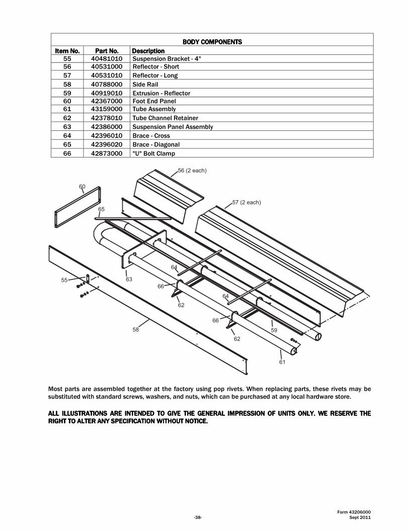
Form 43206000 -38- Sept 2011
BODYBODYBODYBODY COMPONENTSCOMPONENTSCOMPONENTSCOMPONENTS
Item No.Item No.Item No.Item No. Part No.Part No.Part No.Part No. DescriptionDescriptionDescriptionDescription
55 40481010 Suspension Bracket - 4"
56 40531000 Reflector - Short
57 40531010 Reflector - Long
58 40788000 Side Rail
59 40919010 Extrusion - Reflector
60 42367000 Foot End Panel
61 43159000 Tube Assembly
62 42378010 Tube Channel Retainer
63 42386000 Suspension Panel Assembly
64 42396010 Brace - Cross
65 42396020 Brace - Diagonal
66 42873000 "U" Bolt Clamp
56 (2 each)
57 (2 each)
60
65
55
58
63
64
62
66
64
66
62
59
61
Most parts are assembled together at the factory using pop rivets. When replacing parts, these rivets may be substituted with standard screws, washers, and nuts, which can be purchased at any local hardware store.
ALL ILLUSTRATIONS ARE INTENDED TO GIVE THE GENERAL IMPRESSION OF UNITS ONLY. WE RESERVE THE ALL ILLUSTRATIONS ARE INTENDED TO GIVE THE GENERAL IMPRESSION OF UNITS ONLY. WE RESERVE THE ALL ILLUSTRATIONS ARE INTENDED TO GIVE THE GENERAL IMPRESSION OF UNITS ONLY. WE RESERVE THE ALL ILLUSTRATIONS ARE INTENDED TO GIVE THE GENERAL IMPRESSION OF UNITS ONLY. WE RESERVE THE RIGHT TO ALTER ANY SPECIFICATION WITHOUT NOTICE.RIGHT TO ALTER ANY SPECIFICATION WITHOUT NOTICE.RIGHT TO ALTER ANY SPECIFICATION WITHOUT NOTICE.RIGHT TO ALTER ANY SPECIFICATION WITHOUT NOTICE.