installation and operation manual for sea … · sea tel, inc. 4030 nelson avenue concord, ca 94520...
TRANSCRIPT

Sea Tel, Inc. 4030 Nelson Avenue Concord, CA 94520 Tel: (925) 798-7979 Fax: (925) 798-7986 Email: [email protected] Web: www.seatel.com
Look to the Leader. Look to Sea Tel.
Sea Tel Europe Unit 1, Orion Industrial Centre Wide Lane, Swaythling Southampton, UK S0 18 2HJ Tel: 44 (0)23 80 671155 Fax: 44 (0)23 80 671166 Email: [email protected] Web: www.seatel.com
December 20, 2007 Document. No. 124940 Revision A
INSTALLATION AND OPERATION MANUAL
FOR SEA TEL MODEL
14600-50 REDUNDANT C-BAND TX/RX ANTENNAS
WARNING: RF RADIATION HAZARD
This stabilized antenna system is designed to be used with transmit/receive equipment manufactured by others. Refer to the documentation supplied by the manufacturer which will describe potential hazards, including exposure to RF radiation, associated with the improper use of the transmit/receive equipment. Note that the transmit/receive equipment will operate independently of the stabilized antenna system. Prior to work on the stabilized antenna system, the power to the transmit/receive system must be locked out and tagged.
When the transmit/receive system is in operation, no one should be allowed anywhere within the radiated beam being emitted from the reflector.
The ultimate responsibility for safety rests with the facility operator and the individuals who work on the system.
ii
Sea Tel Marine Stabilized Antenna systems are manufactured in the United States of America.
Sea Tel is an ISO 9001:2000 registered company. Certificate Number 19.2867 was issued August 12, 2005. Sea Tel was originally registered on November 09, 1998.
The Series 97 Family of Marine Stabilized Antenna Pedestals with DAC-97 Antenna Control Unit complied with the requirements of European Norms and European Standards EN 60945 (1997) and prETS 300 339 (1998-03) on July 20, 1999. Sea Tel document number 119360 European Union Declaration of Conformity for Marine Navigational Equipment is available on request.
Copyright Notice
All Rights Reserved. The information contained in this document is proprietary to Sea Tel, Inc.. This document may not be reproduced or distributed in any form without the consent of Sea Tel, Inc. The information in this document is subject to change without notice.
Copyright © 2007 Sea Tel, Inc.

iii

iv
Revision History
REV ECO# Date Description By
A N/A December 20, 2007 Initial Production Release includes FCC TX Mute information. MDN

Table of Contents
v
1. INTRODUCTION.................................................................................................................................1-1 1.1. GENERAL DESCRIPTION OF SYSTEM ................................................................................................ 1-1 1.2. PURPOSE ..................................................................................................................................... 1-1 1.3. SYSTEM COMPONENTS.................................................................................................................. 1-1 1.4. GENERAL SCOPE OF THIS MANUAL .................................................................................................. 1-2 1.5. QUICK OVERVIEW OF CONTENTS..................................................................................................... 1-2
2. OPERATION........................................................................................................................................2-1 2.1. SYSTEM POWER-UP....................................................................................................................... 2-1 2.2. ANTENNA INITIALIZATION ............................................................................................................... 2-1 2.3. ANTENNA STABILIZATION ............................................................................................................... 2-2 2.4. STABILIZED PEDESTAL ASSEMBLY OPERATION................................................................................. 2-2 2.5. TRACKING OPERATION................................................................................................................... 2-2 2.6. ANTENNA POLARIZATION OPERATION.............................................................................................. 2-2 2.7. LOW NOISE AMPLIFIER OPERATION ................................................................................................ 2-3 2.8. RF EQUIPMENT............................................................................................................................. 2-3 2.9. RADOME ASSEMBLY OPERATION.................................................................................................... 2-3 2.10. SWITCHING ACTIVE/STANDBY RF EQUIPMENT.................................................................................. 2-3
2.10.1. Transmit Switching .......................................................................................................... 2-3 2.10.2. Receive Path Switching ................................................................................................... 2-4
3. BASIC SYSTEM INFORMATION.......................................................................................................3-1 3.1. SATELLITE BASICS......................................................................................................................... 3-1
3.1.1. C-Band Receive Frequency (3.7-4.2GHz)......................................................................... 3-1 3.1.2. Blockage........................................................................................................................... 3-1 3.1.3. Rain Fade ......................................................................................................................... 3-1 3.1.4. Signal level ....................................................................................................................... 3-2 3.1.5. Satellite Footprints ........................................................................................................... 3-2 3.1.6. Satellite Circular Polarization............................................................................................ 3-2
3.2. ANTENNA BASICS.......................................................................................................................... 3-2 3.2.1. Unlimited Azimuth ........................................................................................................... 3-2 3.2.2. Elevation........................................................................................................................... 3-3 3.2.3. The 3.7 meter antenna..................................................................................................... 3-3 3.2.4. Antenna polarization......................................................................................................... 3-4 3.2.5. Stabilization ...................................................................................................................... 3-4 3.2.6. Search Pattern ................................................................................................................. 3-4 3.2.7. Tracking Receiver - Satellite Identification Receiver........................................................ 3-4 3.2.8. Tracking............................................................................................................................ 3-4
3.3. COMPONENTS OF THE SYSTEM CONFIGURATION .............................................................................. 3-5 3.3.1. Antenna ADE Assembly................................................................................................... 3-5 3.3.2. Antenna Control Unit ....................................................................................................... 3-5 3.3.3. Above Decks AC Power Supply....................................................................................... 3-6
4. INSTALLATION ..................................................................................................................................4-1 4.1. GENERAL CAUTIONS & WARNINGS ................................................................................................. 4-1

Table of Contents
vi
4.2. SITE SURVEY ................................................................................................................................ 4-2 4.3. PREPARING FOR THE INSTALLATION................................................................................................ 4-3
4.3.1. Unpack Shipping Crates................................................................................................... 4-3 4.3.2. Inspect / Inventory ........................................................................................................... 4-3 4.3.3. Prepare ADE Mounting Location ..................................................................................... 4-3 4.3.4. Prepare GPS Mounting Location ..................................................................................... 4-3 4.3.5. Preparing BDE Location ................................................................................................... 4-3 4.3.6. Installing The System Cables........................................................................................... 4-3
4.4. ASSEMBLING THE ADE.................................................................................................................. 4-4 4.4.1. 16’ and 18’ Above Decks Equipment Assembly ............................................................. 4-4 4.4.2. Preparing the ADE for Lift................................................................................................ 4-5
4.5. INSTALLING THE ADE.................................................................................................................... 4-5 4.5.1. Hoist\ ................................................................................................................................ 4-5 4.5.2. Cooling Unit Assembly - TX SYSTEMS ONLY ............................................................... 4-6
4.6. INSTALL BDE EQUIPMENT ............................................................................................................. 4-6 4.6.1. ACU & TMS...................................................................................................................... 4-6 4.6.2. Other BDE Equipment ..................................................................................................... 4-6
4.7. CABLE TERMINATIONS................................................................................................................... 4-6 4.7.1. At The Radome ................................................................................................................ 4-6 4.7.2. ACU & TMS...................................................................................................................... 4-6 4.7.3. Other BDE Equipment ..................................................................................................... 4-6
4.8. FINAL ASSEMBLY .......................................................................................................................... 4-6 4.8.1. Mount RF Equipment (TXRX Only) .................................................................................. 4-6 4.8.2. Remove Stow Braces/Restraints..................................................................................... 4-6 4.8.3. Verify all assembly and Wiring connections .................................................................... 4-6 4.8.4. Balance Antenna Pedestal ............................................................................................... 4-7
4.9. SYSTEM POWER-UP....................................................................................................................... 4-7 4.10. DURING POWER-UP OF THE ADE .................................................................................................. 4-7
4.10.1. Initialization....................................................................................................................... 4-7 4.10.2. Home Flag Position.......................................................................................................... 4-7 4.10.3. BDE .................................................................................................................................. 4-8
4.11. SETUP.......................................................................................................................................... 4-8 5. SETUP .................................................................................................................................................5-1
5.1. OPERATOR SETTINGS .................................................................................................................... 5-1 5.2. OPTIMIZING TARGETING................................................................................................................. 5-1 5.3. CALIBRATING RELATIVE ANTENNA POSITION (HOME FLAG OFFSET).................................................... 5-2
5.3.1. To Calculate HFO: ............................................................................................................ 5-2 5.3.2. To Enter the HFO value: .................................................................................................. 5-4
5.4. RADIATION HAZARD AND BLOCKAGE MAPPING (AZ LIMIT PARAMETERS)........................................... 5-4 5.5. TX POLARITY SETUP...................................................................................................................... 5-7 5.6. ACU FACTORY DEFAULT PARAMETER SETTINGS – 14600 ANTENNAS ................................................ 5-8
6. FUNCTIONAL TESTING.....................................................................................................................6-1

Table of Contents
vii
6.1. ACU / ANTENNA SYSTEM CHECK.................................................................................................... 6-1 6.2. LATITUDE/LONGITUDE AUTO-UPDATE CHECK ................................................................................... 6-1 6.3. HEADING FOLLOWING ................................................................................................................... 6-1 6.4. AZIMUTH & ELEVATION DRIVE........................................................................................................ 6-2 6.5. FOUR QUADRANT TEST TRACKING .................................................................................................. 6-2
7. MAINTENANCE AND TROUBLESHOOTING ...................................................................................7-1 7.1. WARRANTY INFORMATION ............................................................................................................. 7-1 7.2. RECOMMENDED PREVENTIVE MAINTENANCE ................................................................................... 7-2
7.2.1. Check ACU Parameters ................................................................................................... 7-2 7.2.2. Latitude/Longitude Auto-Update check ........................................................................... 7-2 7.2.3. Heading Following ........................................................................................................... 7-2 7.2.4. Azimuth & Elevation Drive ............................................................................................... 7-2 7.2.5. Test Tracking.................................................................................................................... 7-2 7.2.6. Visual Inspection - Radome & Pedestal ......................................................................... 7-2 7.2.7. Mechanical Checks .......................................................................................................... 7-3 7.2.8. Check Balance ................................................................................................................. 7-3 7.2.9. Observe Antenna Initialization ......................................................................................... 7-3
7.3. TROUBLESHOOTING....................................................................................................................... 7-3 7.3.1. Theory Of Stabilization Operation .................................................................................... 7-3 7.3.2. Antenna Initialization (Series 97A & Series 00 )............................................................... 7-4 7.3.3. Antenna Position Error Monitoring .................................................................................. 7-4 7.3.4. Open Loop Rate Sensor Test .......................................................................................... 7-5 7.3.5. Open Loop Rate Sensor Test .......................................................................................... 7-5 7.3.6. Open Loop Motor Test .................................................................................................... 7-6 7.3.7. To Disable/Enable DishScan ............................................................................................ 7-6 7.3.8. Satellite Reference Mode ................................................................................................ 7-6 7.3.9. To Read/Decode an ACU Error Code 0008 (Pedestal Error): ........................................... 7-7 7.3.10. Get Remote GPS LAT/LON Position:............................................................................... 7-8
7.4. MAINTENANCE.............................................................................................................................. 7-8 7.4.1. Balancing the Antenna ..................................................................................................... 7-8 7.4.2. To Adjust Tilt: ................................................................................................................... 7-9 7.4.3. To Reset/Reinitialize the Antenna:................................................................................... 7-9
7.5. PEDESTAL CONTROL UNIT CONFIGURATION (XX97A & XX00) ............................................................ 7-9 7.5.1. If your PCU software version is 1.5x: ............................................................................ 7-10 7.5.2. If your PCU software version is 2.xx: ............................................................................ 7-10
7.6. ANTENNA STOWING PROCEDURE.................................................................................................. 7-11 7.7. SWITCHING ACTIVE/STANDBY RF EQUIPMENT................................................................................ 7-13
7.7.1. Simplified Block Diagrams: ............................................................................................ 7-13 7.7.2. Transmit Signal Path ...................................................................................................... 7-14 7.7.3. Receive Signal Path ....................................................................................................... 7-15 7.7.4. Codan Converter Monitor and Control (M&C) Signal Paths .......................................... 7-15 7.7.5. Paradise Datacom HPA Monitor and Control (M&C) Signal Paths ................................ 7-16

Table of Contents
viii
7.7.6. RF Equipment Physical Configuration............................................................................ 7-16 7.7.7. Codan Equipment Set-up ............................................................................................... 7-16 7.7.8. Paradise Datacom Equipment Set-up ............................................................................ 7-17
7.8. BELOW DECKS RF CONTROL AND SWITCHING ............................................................................... 7-17 7.8.1. RF Equipment M&C Software Options ......................................................................... 7-17 7.8.2. Transmit Switching ........................................................................................................ 7-23 7.8.3. Receive Path Switching ................................................................................................. 7-24
8. 14600-50 TECHNICAL SPECIFICATIONS..........................................................................................8-1 8.1. 14600 C-BAND ANTENNA REFLECTOR............................................................................................ 8-1 8.2. FEED ASSEMBLIES ........................................................................................................................ 8-1
8.2.1. C-Band Circular TXRX Feed Assembly............................................................................. 8-1 8.3. 14600-50 RF EQUIPMENT............................................................................................................. 8-1 8.4. PEDESTAL CONTROL UNIT (PCU) ................................................................................................... 8-1 8.5. STABILIZED ANTENNA PEDESTAL ASSEMBLY.................................................................................... 8-2 8.6. UNLIMITED AZIMUTH MODEMS(4 CHANNEL) ................................................................................... 8-2 8.7. 192” RADOME ASSEMBLY............................................................................................................. 8-3 8.8. ENVIRONMENTAL CONDITIONS (ADE) ............................................................................................. 8-3 8.9. TXRX SYSTEM CABLES ................................................................................................................. 8-4
8.9.1. Antenna Control Cable (Provided from ACU-MUX) ......................................................... 8-4 8.9.2. Antenna Transmit & Receive IF Coax Cables (Customer Furnished) .............................. 8-4 8.9.3. AC Power Cable (Pedestal & Rf Equipment) ................................................................... 8-4
9. DRAWINGS.........................................................................................................................................9-1 9.1. 14600-50 MODEL SPECIFIC DRAWINGS.......................................................................................... 9-1 9.2. SERIES 00 GENERAL DRAWINGS..................................................................................................... 9-1

14600-50 C-Band TXRX Introduction
1-1
1. Introduction
WARNING: RF Radiation Hazard - This stabilized antenna system is designed to be used with transmit/receive equipment manufactured by others. Refer to the documentation supplied by the manufacturer which will describe potential hazards, including exposure to RF radiation, associated with the improper use of the transmit/receive equipment. Note that the transmit/receive equipment will operate independently of the stabilized antenna system.
The ultimate responsibility for safety rests with the facility operator and the individuals who work on the system.
1.1. General Description of system Your Series 00 system is a fully stabilized antenna that has been designed and manufactured so as to be inherently reliable, easy to maintain, and simple to operate. Except for start-ups, or when changing to operate with different transponders or satellites, the equipment essentially permits unattended operation.
1.2. Purpose This shipboard Transmit-Receive (TXRX) system provides you with two-way satellite voice/data communications while underway on an ocean-going vessel. This can be used to provide a wide variety of telephone, fax and data applications. Your Antenna system can transmit to and receive from any desired satellite which has adequate signal coverage in your current geographic area. Your antenna may be fitted with appropriate Transmit & Receive RF Equipment and appropriate Feed to allow you to operate in linear or circular polarization mode at C-Band frequencies. This input will be distributed to your satellite modem and then to all of your other below decks equipment.
1.3. System Components Your TXRX system consists of two major groups of equipment; an above-decks group and a below-decks group. Each group is comprised of, but is not limited to, the items listed below. All equipment comprising the Above Decks is incorporated inside the radome assembly and is integrated into a single operational entity. For inputs, this system requires only an unobstructed line-of-sight view to the satellite, Gyro Compass input and AC electrical power.
For more information about these components, refer to the Basic System Information section of this manual.
A. Above-Decks Equipment (ADE) Group
1. Stabilized antenna pedestal
2. Antenna Reflector
3. Feed Assembly with LNA(s)
4. C-Band Radio Package(s)
5. C-Band High Power Amplifier(s)
6. Radome Assembly
B. Below-Decks Equipment Group
7. Antenna Control Unit
8. Splitter with desired number of outputs (one output to the ACU and one output to the Satellite Modem are required).

Introduction 14600-50 C-Band TXRX
1-2
9. Satellite Modem and other below decks equipment required for the desired communications purposes.
10. Spectrum Analyzer (Optional)
11. Control, RF and Video cables
1.4. General scope of this manual This manual describes the Sea Tel Series 00 Antenna (also called the Above Decks Equipment), its’ operation and installation. Refer to the manual provided with your Antenna Control Unit for its’ installation and operating instructions.
1.5. Quick Overview of contents The information in this manual is organized into chapters. Operation, basic system information, installation, setup, functional testing, maintenance, specifications and drawings relating to this Antenna are all contained in this manual

14600-50 C-Band TXRX Operation
2-1
2. Operation
WARNING: RF Radiation Hazard - This stabilized antenna system is designed to be used with transmit/receive equipment manufactured by others. Refer to the documentation supplied by the manufacturer which will describe potential hazards, including exposure to RF radiation, associated with the improper use of the transmit/receive equipment. Note that the transmit/receive equipment will operate independently of the stabilized antenna system.
The ultimate responsibility for safety rests with the facility operator and the individuals who work on the system.
WARNING: RF Radiation Hazard - When the transmit/receive system is in operation, no one should be allowed anywhere within the radiated beam being emitted from the reflector.
The ultimate responsibility for safety rests with the facility operator and the individuals who work on the system.
2.1. System Power-up Turn the power switch mounted in the aft louvered panel of the antenna pedestal ON. This will energize the antenna pedestal but not the RF equipment. The two sets of RF equipment mounted on the equipment frame (one set on the left and the other on the right) each have their own power switch. Initially these should both be OFF.
Warning: The System has a 20 Amp AC current limit through the AC Power Ring assembly. If both amplifiers are left in the online state the power ring assembly will fail.
Warning: The output of the SECONDARY RF equipment is routed into a 50 ohm terminator. This device is not a “dummy load” that is able to dissipate RF power. If both amplifiers are left in the online state, the 50 ohm terminator will be damaged.
Turn the power switch on rear panel of the Antenna Control Unit (ACU) ON. Be sure to put the SECONDARY RF equipment into “MUTE” condition using you control software.
After the antenna has initialized, turn power to the PRIMARY RF equipment ON. Assure that the secondary RF equipment is in standby “mute” condition before turning power to this set of RF equipment ON.
2.2. Antenna Initialization A functional operation check can be made on the antenna stabilization system by observing its behavior during the 4 phases of initialization.
Turn the pedestal power supply ON. The PCU will initialize the stabilized portion of the mass to be level with the horizon and at a prescribed Azimuth and Elevation angles. The antenna will go through the

Operation 14600-50 C-Band TXRX
2-2
specific sequence of steps (listed below) to initialize the antenna. These phases initialize the level cage, elevation, cross-level and azimuth to predetermined starting positions.
Initialization is completed in the following phases, each phase must complete properly for the antenna to operate properly (post-initialization).
1. Level Cage is driven CCW, issuing extra steps to assure that the cage is all the way to the mechanical stop. Then the Level cage will be driven exactly 45.0 degrees CW.
2. Elevation axis activates - Input from the LV axis of the tilt sensor is used to drive the Elevation of the equipment frame to bring the tilt sensor LV axis to level (this results in the dish being at an elevation angle of 45.0 degrees).
3. Cross-Level axis activates - Input from the CL axis of the tilt sensor is used to drive Cross-Level of the equipment frame to bring the cross-level axis of the tilt sensor to level (this results in the tilt of the Cross-Level Beam being level).
4. Azimuth axis activates - Antenna drives in azimuth until the “Home Flag” signal is produced. This signal is produced by a Home Switch hitting a cam or by a Hall Effect sensor in close proximity to a Magnet.
This completes the phases of initialization. At this time the antenna elevation should 45.0 degrees and Relative azimuth should be at be at home flag (home switch engaged on the home flag cam).
If any of theses steps fail, or the Antenna Control Unit reports model number as "xx97" re-configure the PCU as described in section the Setup section of this manual. If initialization still fails, refer to the troubleshooting section of this manual.
2.3. Antenna Stabilization After initialization has completed, real-time stabilization of the antenna is an automatic function of the PCU.
2.4. Stabilized Pedestal Assembly Operation Operation of the stabilized antenna Pedestal Control Unit (PCU) is accomplished remotely by the Antenna Control Unit (ACU). Refer to the Operation section of the Antenna Control Unit manual for more specific operation details. There are no other operating instructions applicable to the pedestal assembly by itself.
2.5. Tracking Operation Tracking optimizes the antenna pointing, in very fine step increments, to maximize the level of the satellite signal being received. The mode of tracking used in this antenna is a variation of Conical Scanning called DishScan.
DishScan continuously drives the antenna in a very small circular pattern at 60 RPM. The ACU evaluates the received signal throughout each rotation to determine where the strongest signal level is (Up, Right, Down or Left) and issues the appropriate Azimuth and/or Elevation steps to the antenna, as needed.
You cannot control tracking from the pedestal itself. Refer to the ACU manual for tracking operation information.
2.6. Antenna Polarization Operation Linear feeds are equipped with a polarization motor and potentiometer feedback and are controlled from the Antenna Control Unit. When using a linear polarized feed, you should set the POL TYPE parameter in the ACU to 0072 (Auto-Polarization – this mode is the default polarization mode of operation from the ACU).
Circular feeds do NOT require periodic polarization adjustment as the ship travels, but must be assembled correctly for LHCP or RHCP polarization operation (refer to the maintenance section of this

14600-50 C-Band TXRX Operation
2-3
manual). When using a circular polarized feed, you should set the POL TYPE parameter in the ACU to 0000.
2.7. Low Noise Amplifier Operation There are no operating instructions or controls applicable to the LNA. This unit is energized whenever the RF equipment is energized.
2.8. RF Equipment The RF Equipment is not operated or controlled by the antenna pedestal or Antenna Control Unit. Refer to the vendor supplied manuals for the RF Equipment provided with your system. The converter (transceiver) is a Codan 5700 series C band transceiver. The SSPA is a Paradise Datacom Compact Amplifier.
You may have third party software installed in a below-decks computer which is used to control the RF equipment that is mounted on your antenna pedestal.
2.9. Radome Assembly Operation When operating the system it is necessary that the radome access hatch (and/or side door) be closed and secured in place at all times. This prevents rain, salt water and wind from entering the radome. Water and excessive condensation promote rust & corrosion of the antenna pedestal. Wind gusts will disturb the antenna pointing.
There are no other operating instructions applicable to the radome assembly by itself.
2.10. Switching Active/Standby RF Equipment
2.10.1. Transmit Switching The transmit signal path switching is controlled by the Monitor and Control (M&C) software through the Paradise Datacom HPA’s. The primary side HPA1 is ON LINE and MUTED CLEAR state, while the secondary side HPA2 MUST be in a STAND BY and MUTE ON state (known as Cold Standby), to reduce the overall system current draw below 20 amps and to prevent damage to the waveguide terminator.
Warning: For Safety reasons, the maximum current drawn through the AC Power Ring must not exceed 20 Amps. Do NOT allow both amplifiers to be left in the online state. The power ring assembly will be damaged over time. Limit the amount of time that both amplifiers are in the online state to periods of less than 5 minutes.
Warning: The output of the SECONDARY RF equipment is routed into a 50 ohm waveguide terminator. This device is not a “dummy load” that is able to dissipate sustained RF power. If both amplifiers are left in the online state, the 50 ohm terminator will be damaged.
To manually switch from the primary side HPA1 to the secondary side HPA2, first you MUTE the primary HPA1 then switch the secondary HPA2 to ON LINE. The secondary should automatically go from the MUTE ON, to the MUTE CLEAR as follows:

Operation 14600-50 C-Band TXRX
2-4
Start CAM Daemon software.
Log in as Username: admin and Password: admin123.
Select CAM.SSPA.1 & 2 Main windows (shown here with red square and green circle) views for each HPA).
In normal operation, to switch amplifiers, press the red button on the “ONLINE” HPA. (This mutes that HPA and un-mutes the standby making it the “ONLINE” HPA).
2.10.2. Receive Path Switching The receive path switching is controlled through the Antenna Control Unit. Press the MODE key on the front panel of the ACU to access the TRACKING window. Select the appropriate receive signal path by pressing the DOWN arrow as needed (refer to the Operation chapter of the ACU manual MODE – TRACKING – RECEIVE PATH SELECTION). The TRACKING display selections are:
CNV1A Codan Converter 1 & LNA A
CNV1B Codan Converter 1 & LNA B
CNV2A Codan Converter 2 & LNA A
CNV2B Codan Converter 2 & LNA B
This selection remotely controls the Shielded Polang Relay Assembly to actuate an RF Switch to select which converter receive output passes through the dual channel rotary joint to the below decks equipment.

14600-50 C-Band TXRX Basic System Information
3-1
3. Basic System Information This section is intended to provide you with some basic information about satellites, your antenna system and some of the other equipment that may be used in your system configuration.
3.1. Satellite Basics The satellites are in orbit at an altitude of 22,754 miles and are positioned directly above the equator. Their orbital velocity matches the Earth’s rotational speed, therefore, each appears to remain at a fixed position in the sky (as viewed from your location).
Your antenna can be used with any of the satellites in this orbit that have a strong enough receive signal level. Your antenna is capable of being fitted with a Linear or Circular feed assembly. The feed may be designed to operate at C-Band frequencies, Ku-Band frequencies or be capable of operation in both bands. With the correct feed assembly you will be able to receive the linear or circular signal at the specific frequency range of the desired satellite.
3.1.1. C-Band Receive Frequency (3.7-4.2GHz) At these frequencies the signal from the satellite travels only in a straight line and is affected by weather changes in the atmosphere. There are several conditions that can cause a temporary loss of satellite signal, even within an area where the signal level is known to be adequate. The most common of these normal temporary losses are blockage and rain fade. They will interrupt services only as long as the cause of the loss persists.
3.1.2. Blockage Blockage is loss due to an object in the path of the signal from the satellite to the dish. If an object that is large and dense is positioned in the path of the signal from the satellite, it will prevent sufficient signal from arriving at the dish. The signal can not bend around, or penetrate through, these objects and the reception will be degraded or completely interrupted. The dish is actively driven to remain pointed at the satellite (toward the equator) so, as the ship turns a mast or raised structure of your ship may become positioned between the satellite and the dish. Blockage may also be caused a anything standing near the radome, tall mountains, buildings, bridges, cranes or other larger ships near your ship. Moving or rotating the ship to position the antenna where it has an unobstructed view to the desired satellite will restore the antennas’ ability to receive the satellite signal.
3.1.3. Rain Fade Atmospheric conditions that may cause sufficient loss of signal level include rain, snow, heavy fog and some solar activities (sun spot and flare activity). The most common of these is referred to as “rain fade”. Rain drops in the atmosphere reduce the signal from the satellite. The heavier the rain the higher the amount of signal loss. When the amount of loss is high enough, the antenna will not be able to stay locked onto the satellite signal. When the amount of rain has decreased sufficiently, the antenna will re-acquire the satellite signal. In a strong signal area, rain fall of about four inches per hour will cause complete loss of signal. In weaker signal areas the effects would be more pronounced.

Basic System Information 14600-50 C-Band TXRX
3-2
3.1.4. Signal level The level of the receive signal is dependant upon how powerful the transmission is, how wide the signal beam is, and what the coverage area is. Focusing the signal into a narrower beam concentrates its energy over a smaller geographic area, thereby increasing the signal level throughout that area of coverage. This makes it possible for you to use a smaller antenna size to receive that satellite signal. The antenna system must be geographically located in an area where the signal level from the satellite meets (or exceeds) the minimum satellite signal level required for your size of antenna (refer to the Specifications section of this manual) to provide suitable reception. This limits the number of satellites that can be used and the geographic areas where the ship can travel where the signal level is expected to be strong enough to continue providing uninterrupted reception. When traveling outside this minimum signal coverage area, it is normal for the system to experience an interruption in its ability to provide the desired satellite services until entering (or re-entering) an area of adequate signal level.
3.1.5. Satellite Footprints The focused beam(s) from the satellites are normally aimed at the major land masses where there are large population centers. Footprint charts graphically display the signal level expected to be received in different geographic locations within the area of coverage. The signal will always be strongest in the center of the coverage area and weaker out toward the outer edges of the pattern. The coverage areas are intended to be a guide to reception, however, the actual coverage area and signal level and vary. Also the signal strength is affected by weather.
3.1.6. Satellite Circular Polarization When the satellite you are using is transmitting circular polarized satellite transmissions, you will need to set up your feed assembly for RHCP or LHCP to match the “polarization” of your antenna to the satellite. No other adjust is need on the “polarization” during antenna operation
3.2. Antenna Basics The following information is provided to explain some of the basic functions of the antenna:
3.2.1. Unlimited Azimuth Azimuth rotation of the antenna is unlimited (no mechanical stops). Azimuth drive, provided by the azimuth motor, is required during stabilization, searching and tracking operations of the antenna. When the ship turns, azimuth is driven in the opposite direction to remain pointed at the satellite. The actual azimuth pointing angle to the satellite is determined by your latitude & longitude and the longitude of the satellite. It is important to know that the antenna should be pointed (generally) toward the equator.
The azimuth angle to the satellite would be 180 degrees true (relative to true north) if the satellite is on the same longitude that you are on. If the satellite is east, or west, of your longitude the azimuth will be less than, or greater than 180 degrees respectively.
When checking for blockage you can visually look over the antenna radome toward the equator to see if any objects are in that sighted area. If you are not able to find any satellites it may also be useful to remove the radome hatch to visually see if the dish is aimed the correct direction (towards the equator).

14600-50 C-Band TXRX Basic System Information
3-3
3.2.2. Elevation In normal operation the elevation of the antenna will be between 00.0 (horizon) and 90.0 (zenith). The antenna can physically be rotated in elevation below horizon and beyond zenith to allow for ship motion. Elevation drive, provided by the elevation motor, is required during stabilization, searching and tracking operations of the antenna. The actual elevation pointing angle to the satellite is determined by your latitude & longitude and the longitude of the satellite. In general terms the elevation angle will be low when you are at a high latitudes and will increase as you get closer to the equator.
Additionally, from any given latitude, the elevation will be highest when the satellite is at the same longitude that you are on. If the satellite is east, or west, of your longitude the elevation angle will be lower.
3.2.3. The 3.7 meter antenna The signal from the satellite bounces off of the main reflector, is focused up to and reflects off of the sub-reflector and is focused down into the feed assembly. It then passed through the phase card polarizer where the circular polarization is converted into linear and is passed into the OMT (Ortho Mode Transducer). The receive signal from the polarizer is sent out the RX Port of the OMT. The transmit signal enters the TX port on the OMT is converted to circular by the phase card polarizer, emits out of the feed, reflects off of the sub-reflector and then off of the main reflect and is radiated out to the satellite.
Satellite Signal
3.2.3.1. Feed Assembly
The Suman 3.7 meter feed is circular polarized. You must manually adjust the position of the OMT on the Polarizer to select either LHCP Left Hand circular polarization or RHCP Right Hand polarization required by the satellite.
The receive port of the OMT has a 60 dB TX reject filter to protect the LNA.

Basic System Information 14600-50 C-Band TXRX
3-4
3.2.4. Antenna polarization The Suman 3.7 meter feed is circular polarized. You must manually align the position of the OMT on the Polarizer to set the Transmit (or Receive) port to the either Left Hand Circular Polarity (LHCP) or Right Hand Circular Polarity (RHCP) as required by the satellite.
3.2.5. Stabilization Your antenna is stabilized in all three axes of motion. Stabilization is the process of de-coupling the ships’ motion from the antenna. Simply put, this allows the antenna to remain pointed at a point in space while the boat turns, rolls or pitches under it. To accomplish this, the Pedestal Control Unit (PCU) on the antenna pedestal assembly senses the motion and applies drive to the appropriate motor(s) in opposition to the sensed motion. Azimuth (AZ), Elevation (EL) and Cross-Level (left-right tilt) are actively stabilized automatically by the PCU as part of its normal operation.
3.2.6. Search Pattern Whenever the desired satellite signal is lost (such as when the antenna is blocked) the Antenna Control Unit will automatically initiated a Search to re-acquire the desired signal.
Search is conducted in a two-axis pattern consisting of alternate movements in azimuth and elevation. The size and direction of the movements are increased and reversed every other time resulting in an expanding square pattern.
When the antenna is able to re-acquire the desired signal the ACU will automatically stop searching and begin Tracking the signal to optimize the pointing of the antenna to get the highest signal level from the satellite.
3.2.7. Tracking Receiver - Satellite Identification Receiver The Satellite Identification Receiver located in the Antenna Control Unit (ACU) is used to acquire, identify and track a specific satellite by its unique hexadecimal ID code. When properly setup, the settings for the satellite are saved to expedite future acquisition of the desired satellite.
When searching for the selected satellite this receiver compares the present satellite ID to the targeted satellite ID code. If the ID code does not match the antenna will continue searching until the correct satellite is found. The system must have adequate satellite signal level, AND the matching NID, to stop searching (and begin tracking the desired satellite).
3.2.8. Tracking Your Antenna Control Unit actively optimizes the pointing of the dish for maximum signal reception. This process is called tracking and is accomplished by continuously making small movements of the dish while monitoring the level of the received signal. Evaluation of this information is used to continuously move the stabilization point toward peak satellite signal reception. These minor pointing corrections keep the signal level “peaked” as part of normal operation.

14600-50 C-Band TXRX Basic System Information
3-5
3.3. Components of the System Configuration The following text provides a basic functional overview of the system components and component interconnection as referred to in the simplified block diagram (see drawings section of this manual).
3.3.1. Antenna ADE Assembly The Above Decks Equipment consists of an Antenna Pedestal inside a Radome assembly. The pedestal consists of a satellite antenna dish & circular feed assembly, redundant RF components and RF path switching components mounted on a stabilized antenna pedestal. The radome provides an environmental enclosure for the antenna pedestal assembly inside it. This keeps wind, water condensation and salt-water spray off the antenna pedestal assembly. This prevents damage and corrosion that would shorten the expected life span of the equipment.
Two coaxial cables are connected from the antenna radome assembly to the below decks equipment. One of these cables includes the Antenna Control signaling and IF, the other cable carries the other IF signal.
These cables ultimately provide the input/output signals into/out of the satellite modem.
3.3.2. Antenna Control Unit The Antenna Control Unit allows the operator to control and monitor the antenna pedestal with dedicated function buttons, LED’s and a 2 line display. The ACU and its Terminal Mounting Strip are normally mounted in a standard 19” equipment rack. The ACU should be mounted in the front of the equipment rack where it is easily accessible. The Terminal Mounting Strip is normally mounted on the rear of the equipment rack. It is recommended that the antenna control panel be mounted near the modem, or one of the Satellite Receiver locations, where you can see the effect you are having on the satellite signal as you are controlling the antenna.
The Antenna Control Unit is connected to the antenna, ships Gyro Compass and to the GPS Engine (when included).
Figure 3-1 DAC Antenna Control Unit
The Antenna Control Unit (ACU) communicates via an RS-422 serial data link with the Pedestal Control Unit (PCU) located on the antenna. This control signal is converted to RF and sent up one the Antenna coax cables to the pedestal where it is converted back to RS-422 to the PCU. The Pedestal Control Unit stabilizes the antenna against the ship's roll, pitch, and turning motions. The ACU is the operator interface to the PCU and provides the user with a choice of positioning commands to point the antenna, search commands to find the satellite signal and tracking functions to maintain optimum pointing.

Basic System Information 14600-50 C-Band TXRX
3-6
3.3.3. Above Decks AC Power Supply Power for the Antenna Pedestal and RF Equipment (TX/RX Systems ONLY) - The AC Voltage required for the 14600 antenna is 220 VAC due to the current draw required to operate the antenna, plus the redundant transceivers and amplifiers. Total power consumption will depend on the number of type of transceivers and amplifiers used. The pedestal itself requires only 290 watts. CAUTION: The High powered redundant RF Equipment power consumption is near 4000 watts total. Sea Tel Recommends that the back up set of RF Equipment be run in its lowest power state which will drop the power consumption to 2500 watts. The AC voltage source should be well regulated and surge protected. Uninterrupted Power Supplies are frequently installed (below decks) to provide power for the antenna pedestal, especially if RF Equipment is installed on the pedestal.
Marine Air Conditioner Unit (TX/RX Systems ONLY) - If a marine air conditioner is included with your system, the AC voltage source should be from a separate AC Power breaker source than the antenna pedestal. AC power for the air conditioner should be well regulated and surge protected, but does NOT need to from an Uninterrupted Power Supply. Refer to the marine air conditioner manual for its’ power requirements and consumption specifications.

14600-50 C-Band TXRX Installation
4-1
4. Installation This section contains instructions for unpacking, final assembly and installation of the equipment. It is highly recommended that final assembly and installation of the Antenna system be performed by trained technicians. Read this complete section before starting.
4.1. General Cautions & Warnings
WARNING: Assure that all nut & bolt assemblies are tightened according the tightening torque values listed below:
Bolt Size Inch Pounds
1/4-20 75
5/l6-18 132
3/8-16 236
1/2-13 517
NOTE: All nuts and bolts should be assembled using the appropriate Loctite thread-locker product number for the thread size of the hardware.
Loctite # Description
222 Low strength for small fasteners.
243 Medium strength, oil tolerant.
680 High strength for Motor Shafts & Sprockets.
271 Permanent strength for up to 1” diameter fasteners.
290 Wicking, High strength for fasteners which are already assembled.
WARNING: Hoisting with other than a webbed four-part sling may result in catastrophic crushing of the radome. Refer to the specifications and drawings for the fully assembled weight of your model Antenna/Radome and assure that equipment used to lift/hoist this system is rated accordingly.
CAUTION: The antenna/radome assembly is very light for its size and is subject to large swaying motions if hoisted under windy conditions. Always ensure that tag lines, attached to the radome base frame, are attended while the antenna assembly is being hoisted to its assigned location aboard ship.
WARNING: Electrical Hazard – Dangerous AC Voltages exist inside the Antenna Pedestal Breaker Box. Observe proper safety precautions when working inside the Pedestal Breaker Box.
WARNING: Electrical Hazard – Dangerous AC Voltages exists on the side of the Antenna Pedestal Power Supply. Observe proper safety precautions when working inside the Pedestal Power Supply.

Installation 14600-50 C-Band TXRX
4-2
WARNING: RF Radiation Hazard - This stabilized antenna system is designed to be used with transmit/receive equipment manufactured by others. Refer to the documentation supplied by the manufacturer which will describe potential hazards, including exposure to RF radiation, associated with the improper use of the transmit/receive equipment. Note that the transmit/receive equipment will operate independently of the stabilized antenna system.
The ultimate responsibility for safety rests with the facility operator and the individuals who work on the system.
WARNING: RF Radiation Hazard - Prior to working on the stabilized antenna system, the power to the transmit/receive equipment must be locked out and tagged. Turning OFF power to the Antenna Control Unit does NOT turn Transmit power output OFF.
The ultimate responsibility for safety rests with the facility operator and the individuals who work on the system.
WARNING: RF Radiation Hazard - When the transmit/receive system is in operation, no one should be allowed anywhere within the radiated beam being emitted from the reflector.
The ultimate responsibility for safety rests with the facility operator and the individuals who work on the system.
4.2. Site Survey The radome assembly should be installed at a location aboard ship where:
1. The antenna has a clear line-of-sight to as much of the sky (horizon to zenith at all bearings) as is practical.
2. Direct radiation into the antenna from ships radar, especially high power surveillance radar arrays, is minimized. The radome should be as far away from the ships Radar as possible and should NOT be mounted on the same plane as the ships Radar (so that it is not directly in the Radar beam path).
3. The radome should be as far away from the ships high power short wave (MF & HF) transmitting antennas as possible.
4. The Above Decks Equipment (ADE) and the Below Decks Equipment (BDE) should be positioned as close to one another as possible. This is necessary to reduce the losses associated with long cable runs.
5. The mounting location is rigid enough that it will not flex, or sway, in ships motion or vibration. If the radome is to be mounted on a raised pedestal, it MUST have adequate gussets, or be well guyed, to prevent flexing or swaying in ships motion.
If these conditions cannot be entirely satisfied, the site selection will inevitably be a “best” compromise between the various considerations.

14600-50 C-Band TXRX Installation
4-3
4.3. Preparing For The Installation
4.3.1. Unpack Shipping Crates Exercise caution when unpacking the equipment.
4.3.2. Inspect / Inventory Carefully inspect the radome panel surfaces for evidence of shipping damage. Inspect the pedestal assembly and reflector for signs of shipping damage.
4.3.3. Prepare ADE Mounting Location Prepare the mounting location for the Radome. If the radome is to be bolted to the deck (or a platform) assure that the mounting holes have been drilled. Assure that the mounting hardware has obtained and is readily available.
4.3.4. Prepare GPS Mounting Location Prepare the mounting location (deck or handrail) for the GPS. Assure that the mounting hardware is readily available.
4.3.5. Preparing BDE Location Prepare the mounting location for the Below Decks Equipment. These equipments would normally be installed in a standard 19” equipment rack. Refer to the Antenna Control Unit manual for installation of the ACU and the Terminal Mounting Strip.
Refer to the vendor supplied manuals for installation of the other below decks equipments.
Prepare other locations throughout ship for any other equipment which is not co-located with the ACU.
4.3.6. Installing The System Cables Install appropriate cables from Below Decks Equipment to the ADE Location(s).
The cables must be routed from the above-decks equipment group through the deck and through various ship spaces to the vicinity of the below-decks equipment group. When pulling the cables in place, avoid the use of excessive force. Exercise caution during the cable installation to assure that the cables are not severely bent (proper bend radius), kinked or twisted and that connectors are not damaged.
Assure that the cables have been run through watertight fittings and/or will not permit water entry into the ship when the installation is completed. After cables have been routed and adjusted for correct cable length at each end, seal the deck penetration glands and tie the cables securely in place.

Installation 14600-50 C-Band TXRX
4-4
4.4. Assembling the ADE
4.4.1. 16’ and 18’ Above Decks Equipment Assembly Refer to the System Block diagram, General Assembly, Radome Assembly and Baseframe Assembly drawings for your system.
NOTE: Unless otherwise indicated, all nuts and bolts should be assembled with Loctite 271 or its equivalent.
WARNING: Assure that all nut & bolt assemblies are tightened according the tightening torque values listed below:
Bolt Size Inch Pounds
1/4-20 75
5/l6-18 132
3/8-16 236
1/2-13 517
1. Select a secure assembly site that provides enough area to work with the large radome panels. Place the radome base pan on temporary support blocks at least 22 inches high.
2. Assemble the radome base frame, eight legs and eight braces using the hardware provided. Loosely assemble all legs and braces aligning all matching marks before tightening any of the bolts. Insure that Loctite and a split washer is used under each nut.
3. Refer to the radome assembly drawing. Observe the painted numbers on the radome panels that clearly identify their positions respective to each other and the base pan assembly.
4. Loosely assemble the 6 lower side panels, using the hardware provided, to form the bottom half of the radome. Do NOT tighten the bolts at this time. Open each seam wide enough to install a good bead of silicone caulk, then firmly tighten all the bolts in that flange. Repeat until all flanges are sealed.
5. Loosely assemble the 6 upper side panels, using the hardware provided, to form the upper half of the radome. Do NOT tighten the bolts at this time. Open each seam wide enough to install a good bead of silicone caulk, then firmly tighten all the bolts in that flange. Repeat until all flanges are sealed.
6. Apply a good bead of silicone caulk all the way around the top cap. Install the cap into the upper radome panel assembly using the hardware provided and tighten all the bolts.
7. Set the lower half of the radome assembly on the base pan aligning the painted numbers on the radome panels. Loosely attach the lower side panel assembly to the base frame using the hardware provided. Do NOT tighten the bolts at this time. Lift the lower side panel assembly up wide enough to install a good bead of silicone caulk between it and the base pan, then firmly tighten all the bolts.
8. Lift the antenna pedestal up and set it in place on the base pan inside the lower half of the radome. Fasten the antenna pedestal assembly, complete with base stand, to the base pan using the 1/2-13 x 1 1/2 (or the 3/8-16 x 1 1/2) inch bolts inserted from the

14600-50 C-Band TXRX Installation
4-5
bottom up. Install a flat washer, a lock washer and a nut in each mounting hole. Apply Loctite 271 and tighten securely.
9. Attach the antenna assembly (reflector, struts and feed) to the stabilized pedestal, by using the reflector mounting hardware provided. Position the antenna over the four antenna support struts (the antenna and the dish mounting clips are numbered or color coded make sure they match). Insert the four mounting bolts, washers and nuts, apply Loctite 271 and tighten.
10. Attach the 15 pin connector on the antenna reflector harness to the shielded Polang Aux Relay box. Connect the IF receive coax cables from the feed to the pedestal Modem or coax relay/switch panel according to the block diagram.
11. Using a EIGHT point web lifting sling and lifting clips, lift the upper half of the radome up over the antenna pedestal and set it onto the lower side panels aligning the painted numbers on the radome panels. Loosely attach the upper and lower halves of the radome using the hardware provided. Do NOT tighten the bolts at this time. Insert wedges between the upper side panel assembly and the lower side panel assembly to hold open a space wide enough to install a good bead of silicone caulk between it and the lower side panels, then remove the wedges and firmly tighten all the bolts.
12. Gently restrain the antenna prior to lifting the ADE onto the ship to restrict movement inside the radome during the lift.
4.4.2. Preparing the ADE for Lift Install Stow Braces, or other restraints, on the Antenna Pedestal. Attach shackles and web type lifting harness to the four lifting holes in the base-frame.
4.5. Installing The ADE
4.5.1. Hoist\
WARNING: Hoisting with other than a webbed four-part sling may result in catastrophic crushing of the radome. Refer to the specifications and drawings for the fully assembled weight of your model Antenna/Radome and assure that equipment used to lift/hoist this system is rated accordingly.
CAUTION: The antenna/radome assembly is very light for its size and is subject to large swaying motions if hoisted under windy conditions. Always ensure that tag lines, attached to the radome base frame, are attended while the antenna assembly is being hoisted to its assigned location aboard ship.
1. Assure that the antenna is restrained before hoisting. Check that all nuts on the base frame assembly are tightened according the torque values listed below:
2. Using a four-part lifting sling, and with a tag line attached to the radome base frame, hoist the antenna assembly to its assigned location aboard ship by means of a suitably-sized crane or derrick.
3. The radome assembly should be positioned with the BOW marker aligned as close as possible to the ship centerline. Any variation from actual alignment can be compensated with the AZIMUTH TRIM adjustment in the ACU, so precise alignment is not required.

Installation 14600-50 C-Band TXRX
4-6
4.5.2. Cooling Unit Assembly - TX SYSTEMS ONLY If cooling unit is supplied, refer to the drawings provided for detailed instructions on assembly and installation of the cooling unit and any associated intake and exhaust diffusion ducting.
4.6. Install BDE Equipment
4.6.1. ACU & TMS Refer to the Antenna Control Unit manual for installation of the ACU and the Terminal Mounting Strip.
4.6.2. Other BDE Equipment Refer to the vendor supplied manuals for installation of the other below decks equipment.
4.7. Cable Terminations
4.7.1. At The Radome The TX and RX IF, cables must be inserted through the cable strain reliefs at the base of the radome. Apply RTV to the strain relief joints and tighten the compression fittings to make them splash-proof. Attach the TX and RX IF, cables from below decks to the TX and RX pedestal cable adapters (refer to the System Block Diagram).
Route the AC Power cable for the Antenna Pedestal and RF Equipment into the Breaker box in the aft louvered panel and connected the conductors to the appropriate breaker terminals.
Sea Tel recommends that separate, dedicated, AC Power be provided for the Marine Air Conditioner (Do NOT combine with the AC Power provided for the Antenna Pedestal and RF Equipment). This AC Power cable is routed into the Marine Air Conditioner and terminated to the AC terminals inside.
4.7.2. ACU & TMS To Connect AC Power, Gyro Compass Connection and IF Input refer to the Antenna Control Unit manual. Installation of optional (remote) Pedestal, and /or Radio, Monitor & Control connection(s) from a PC Computer are also contained in the ACU manual.
4.7.3. Other BDE Equipment Refer to the vendor supplied manuals for installation of the other below decks equipment.
4.8. Final Assembly
4.8.1. Mount RF Equipment (TXRX Only) Install the RF equipment on the elevation beams (TXRX Systems ONLY) Connect the TXIF & RXIF cables, RF Transmit and Receive waveguide sections from the appropriate feed (C-Band or Ku-Band) to the appropriate SSPA or TWTA and Radio package (C-Band Pair or Ku-Band pair) according to the block diagram.
4.8.2. Remove Stow Braces/Restraints Remove the restraints from the antenna and verify that the antenna moves freely in azimuth, elevation, and cross level without hitting any flanges on the radome.
4.8.3. Verify all assembly and Wiring connections Verify that all pedestal wiring and cabling is properly dressed and clamped in place.

14600-50 C-Band TXRX Installation
4-7
4.8.4. Balance Antenna Pedestal Assure that the antenna assembly is balanced front to back, top to bottom and side to side by observing that it remains stationary when positioned in any orientation. Refer to the Maintenance section for complete information on balancing the antenna.
4.9. System Power-up Turn the power switch mounted in the aft louvered panel of the antenna pedestal ON. This will energize the antenna pedestal but not the RF equipment. The two sets of RF equipment mounted on the equipment frame (one set on the left and the other on the right) each have their own power switch. Initially these should both be OFF.
Warning: For Safety reasons, the maximum current drawn through the AC Power Ring must not exceed 15 Amps. Do NOT allow both amplifiers to be left in the online state. The power ring assembly will be damaged over time. Limit the amount of time that both amplifiers are in the online state to periods of less than 5 minutes.
Warning: The output of the SECONDARY RF equipment is routed into a 50 ohm waveguide terminator. This device is not a “dummy load” that is able to dissipate sustained RF power. If both amplifiers are left in the online state, the 50 ohm terminator will be damaged.
Turn the power switch on rear panel of the Antenna Control Unit (ACU) ON. Be sure to put the SECONDARY RF equipment into “MUTE” condition using you control software.
After the antenna has initialized, turn power to the PRIMARY RF equipment ON. Assure that the secondary RF equipment is in standby “mute” condition before turning power to this set of RF equipment ON.
4.10. During Power-Up Of The ADE
4.10.1. Initialization Turn the pedestal power supply ON. The PCU will initialize the stabilized portion of the mass to be level with the horizon and at a prescribed Azimuth and Elevation angles. The antenna will go through the specific sequence of steps to initialize the level cage, elevation, cross-level and azimuth to predetermined starting positions. Each phase must complete properly for the antenna to operate properly (post-initialization). Refer to the initialization text in the Troubleshooting section in this manual. Observe the Initialization of the antenna pedestal.
If any of these steps fail, or the ACU reports model "xx97", re-configure the PCU as described in the Setup section of this manual. If initialization still fails, this indicates a drive or sensor problem, refer to the Troubleshooting section.
4.10.2. Home Flag Position Note the approximate position of the antenna relative to the bow of the ship while it is at the home switch position. This information will be used later to calibrate the relative position display of the antenna.

Installation 14600-50 C-Band TXRX
4-8
4.10.3. BDE Turn Power ON to the ACU. Record the power-up display, Master (ACU) Model & Software version and the Remote (PCU) Model & Software version.
4.11. Setup Refer to the Setup information in the next section of this manual and in the Setup section of your ACU Manual.

14600-50 C-Band TXRX Setup
5-1
5. Setup Below are basic steps to guide you in setting up the ACU for your specific antenna pedestal. Assure that the Antenna Pedestal (ADE) has been properly installed before proceeding. Refer to the Setup section of you ACU manual for additional parameter setting details.
5.1. Operator Settings Refer to the Operation chapter of this manual to set the Ship information. Latitude and Longitude should automatically update when the GPS engine mounted above decks triangulates an accurate location, but you may enter this information manually to begin. You will have to enter Heading of the current heading of the ship, the Gyro Compass will then keep the ACU updated.
Set the Satellite information, for the satellite you will be using. The receiver settings are especially important. At this point you should be able to target the desired satellite. Continue with the setup steps below to optimize the parameters for your installation.
5.2. Optimizing Targeting First, assure that all of your Ship & Satellite settings in the ACU are correct. Target the desired satellite, immediately turn Tracking OFF, and record the Azimuth and Elevation positions in the “ANTENNA“ display of the ACU (these are the Calculated positions). Turn Tracking ON, allow the antenna to “Search” for the targeted satellite and assure that it has acquired (and peaks up on) the satellite that you targeted. Allow several minutes for the antenna to “peak” on the signal, and then record the Azimuth and Elevation positions while peaked on satellite (these are the Peak positions). Again, assure that it has acquired the satellite that you targeted!
Subtract the Peak Positions from the Calculated Positions to determine the amount of Trim which is required. Refer to the ACU Setup information to key in the required value of Elevation Trim. Continue with Azimuth trim, then re-target the satellite several times to verify that targeting is now driving the antenna to a position that is within +/- 1.0 degrees of where the satellite signal is located.
EXAMPLE: The ACU targets to an Elevation position of 30.0 degrees and an Azimuth position of 180.2 (Calculated), you find that Peak Elevation while ON your desired satellite is 31.5 degrees and Peak Azimuth is 178.0. You would enter an EL TRIM value of –1.5 degrees and an AZ TRIM of +2.2 degrees. After these trims values had been set, your peak on satellite Azimuth and Elevation displays would be very near 180.2 and 30.0 respectively.

Setup 14600-50 C-Band TXRX
5-2
Figure 5-1 Antenna stops In-line with Bow
5.3. Calibrating Relative Antenna Position (Home Flag Offset) During initialization, azimuth drives the CW antenna until the Home Switch is contacted, which “presets” the relative position counter to the value stored in the Home Flag Offset. This assures that the encoder input increments/decrements from this initialization value so that the encoder does not have to be precision aligned.
The Home Switch is a micro switch with a roller arm which is actuated by cam mounted on the azimuth driven sprocket, or it is a hall sensor which is actuated by a magnet mounted on the azimuth driven sprocket, which produces the “Home Flag” signal.
The Home Flag Offset is a value saved in NVRam (Non-Volatile RAM) in the PCU. This value is the relative position of the antenna when the home switch is engaged. Presetting the counter to this value assures that when the antenna is pointed in-line with the bow of the ship the counter will read 000.0 Relative (360.0 = 000.0).
In most cases when the antenna stops at the home flag, it will be pointed in-line with the Bow of the ship. In these cases Home Flag Offset (HFO) should be set to zero. When “Optimizing Targeting” small variations (up to +/- 5.0 degrees) in Azimuth can be corrected using If it AZ TRIM as described in the Optimizing Targeting procedure above.
Large variations in Azimuth position indicate that the Relative position is incorrect and should be “calibrated” using the correct HFO value instead of an Azimuth Trim offset. This is especially true if sector blockage mapping is used.
If the antenna stops at the home flag, but it is NOT pointed in-line with the Bow of the ship, it is important to assure that the antennas actual position (relative to the bow of the ship) is the value that gets “preset” into the Relative position counter. By saving the antennas actual Relative position when at the home flag into HFO, you have calibrated the antenna to the ship.
5.3.1. To Calculate HFO: If Targeting has been optimized by entering a large value of AZ TRIM; First, verify that you are able to repeatably accurately target a desired satellite (within +/- 1.0 degrees). Then you can use the AZ TRIM value to calculate the value of HFO you should use (so you can set AZ TRIM to zero). AZ Trim is entered as the number of tenths of degrees. You will have to convert the AZ TRIM value to the nearest whole degree (round up or down as needed). Calculated HFO value is also rounded to the nearest whole number.
If AZ TRIM was a plus value: HFO = (TRIM / 360) x 255 Example: AZ TRIM was 0200 (plus 20 degrees). HFO = (20/360) x 255 = (0.0556) x 255 = 14.16 round off to 14.
If AZ TRIM was a negative value: HFO = ((360-TRIM) / 360)) x 255 Example: AZ TRIM = -0450 (minus 45 degrees). HFO = ((360 – 45) / 360)) x 255 = (315 / 360) x 255 = 0.875 x 255 = 223.125 round of to 223.
If Targeting has NOT been optimized, allow the antenna to initialize to its home flag position. Visually compare the antennas pointing to the bow-line of the ship (parallel to the Bow). Note the antennas position relative to the Bow. If it appears to be very close to being parallel to the bow, HFO will probably not be needed and you can proceed with Optimizing Targeting. If it is NOT close, initialization was driving the azimuth CW, note if the antenna appears to have

14600-50 C-Band TXRX Setup
5-3
Figure 5-2 Antenna stopped before the Bow
Figure 5-3 Antenna stops past the Bow
stopped before it got to the Bow or if it went past the Bow. You may be able to guess an approximate amount of how many degrees the antenna is from the bow. This is only intended to help you initially find the satellite (which direction you will have to drive and approximately how far you will have to drive). Refer, in general terms, to the Optimizing Targeting procedure.
If the antenna stopped before it got to the bow-line; When you initially target a satellite, the antenna will also stop prior to the satellite position, so you that will have to drive the Azimuth of the antenna UP to actually find the satellite. Using the same basic procedure as in the Optimizing Targeting paragraph, target the satellite and record the “Calculated” Azimuth position that the antenna was driven to. Drive UP until you find the satellite, positively identify that you are on the satellite you targeted and allow tracking to peak the antenna position. Record the “Peak” Azimuth position. Subtract the “Peak” position from the “Calculated” position to determine the number of degrees of AZ TRIM that would be required.
Example: In this new installation, I target my desired satellite and record the Calculated Azimuth to be 180.5. I drive UP and finally find my desired satellite at a Peak Azimuth of 227.0 degrees. I subtract Peak from Calculated and difference to be –46.5 degrees, therefore the actual Relative position that needs to be preset into the counter when the antenna is at the Home Flag is 313.5. HFO = ((360-46.5) / 360)) x 255 = (313.5 / 360) x 255 = 0.87 x 255 = 222.06 which I round down to 222.
If the antenna went past the bow-line; When you initially target a satellite, the antenna will also go past the satellite position, so that you will have to drive the Azimuth of the antenna DOWN to actually find the satellite. Using the same basic procedure as in the Optimizing Targeting paragraph, target the satellite and record the “Calculated” Azimuth position that the antenna was driven to. Drive DOWN until you find the satellite, positively identify that you are on the satellite you targeted and allow tracking to peak the antenna position. Record the “Peak” Azimuth position. Subtract the “Peak” position from the “Calculated” position to determine the number of degrees of AZ TRIM that would be required. . Refer to the calculations above to determine the HFO you should use for this antenna.
Example: In this new installation, I target my desired satellite and record the Calculated Azimuth to be 180.0. I drive DOWN and finally find my desired satellite at a Peak Azimuth of 90.0 degrees. I subtract Peak from Calculated and difference to be +90.0 degrees, therefore the actual Relative position

Setup 14600-50 C-Band TXRX
5-4
that needs to be preset into the counter when the antenna is at the Home Flag is 90.0. HFO = ((90.0) / 360)) x 255 = 0.25 x 255 = 63.75 which I round up to 64.
5.3.2. To Enter the HFO value: To enter the calculated HFO value, press Antenna Control Unit MODE key repeatedly, enter the password ant the REMOTE AUX menu and then continue pressing the MODE key until you have selected the REMOTE COMMAND window.
In the REMOTE COMMAND window, key in ".78” and hit the ENTER key. "N0000" should appear in the command window. Key in 6 and the three digit HFO value from 000 to 255 (corresponding to 0 to 360 degrees) that you calculated above. Press ENTER to send the HFO value command to the PCU. Press ENTER several times to select the REMOTE PARAMETERS display. Press the UP arrow key and then press the ENTER to save the HFO value in the PCUs NVRAM.
If you want to find out what the current HFO value is key in 6999 and hit ENTER.
EXAMPLE: In the “Antenna stopped before the Bow” example above, the HFO calculated was 222. To enter this value:
1. Key in "6222" to set HFO to 222. The display should now show "N0222".
2. Press ENTER to send this HFO to the PCU.
3. Press ENTER (or MODE) several times to select REMOTE PARAMETERS. Press UP arrow and then ENTER to save the HFO to NVRAM in the PCU.
4. Press ANTENNA twice, and manually drive the antenna toward the Home Switch (or re-Initialize the antenna). The Home Switch must actuate to preset the counter to the new value before you target the satellite again! Now, whenever the Home Switch is actuated, the new value of HFO (the actual Relative position of the antenna) will be loaded into the Relative counter.
5. If there was previously a positive or negative value of AZ TRIM, set it to zero and SAVE NEW PARAMETERS.
6. Follow the Optimizing Targeting procedure to re-evaluate small corrections in EL TRIM and AZ TRIM and verify that you can repeatedly target a desired satellite (within +/- 1 degree, or less).
If your antenna is periodically blocked by some part of the ships structure, you may want to refer to the Radiation Hazard and Blockage Mapping section below.
5.4. Radiation Hazard and Blockage Mapping (AZ LIMIT parameters) The ACU can be programmed with relative azimuth sectors (zone) where blockage exists or where transmit power would endanger personnel who are frequently in that area.
When the AZ LIMIT parameters are set to create these ZONES, up to three, several things happen when the antenna is within one of the zones:
1. Tracking continues as long as the AGC value is greater than the Threshold value. When the AGC value drops below Threshold the antenna will wait “Search Delay” parameter amount of time and then re-target the satellite you targeted last. Timeout and re-target will continue until the satellite is re-acquired and tracking can resume.
2. “BLOCKED” will be displayed in the TRACKING window wherever the antenna is inside one of the zones.
3. A contact closure to ground (or an open if the blockage logic is reversed – See SYSTEM TYPE 16 value) is provided on the SW2 terminal of the Terminal Mounting Strip. This Switch output provides a “Blocked”, “RF Radiation Hazard” or “FCC TX Mute” logic output. When the antenna exits the zone it will be on satellite, tracking and the SW2 logic contact closure will open.

14600-50 C-Band TXRX Setup
5-5
The lower and upper limits are user programmable and are stored in NVRAM within the ACU parameter list.
AZ LIMIT 1 is the Lower Relative AZ limit (this is the more counter-clockwise of the two points, even if it is numerically larger). AZ LIMIT 2 is the Upper Relative AZ limit (the more clockwise of the two points) for pattern mapping of ZONE 1.
AZ LIMIT 3 is the Lower Relative AZ limit (CCW point) and AZ LIMIT 4 is the Upper Relative AZ limit (CW point) for pattern mapping of ZONE 2.
AZ LIMIT 5 is the Lower Relative AZ limit (CCW point) and AZ LIMIT 6 is the Upper Relative AZ limit (CW point) for pattern mapping of ZONE 3.
CAUTION: The Lower Relative AZ limit is the more counter-clockwise of the two points (even if it is numerically larger) and the Upper Relative AZ limit is the more clockwise of the two points. If you enter the two relative points incorrectly, Tracking and Searching will be adversely affected.
The ACU provides a contact closure to ground on the SW2 terminal of the Terminal Mounting Strip when the antenna is pointed within any one of the blockage/hazard zones or the system is searching, targeting, unwrapping or is mis-pointed by 0.5 degrees or more (FCC TX Mute function for Transmit/Receive systems only). The contact closure is a transistor switch with a current sinking capability of 0.5 Amp. Refer to your ACU Manual for instructions on how to simulate a manual BLOCKED condition to test the SW2 logic output.
When used as simple “BLOCKED” logic output for a single Sea Tel antenna, this output could be used to light a remote LED and/or sound a buzzer to alert someone that the antenna is blocked, and therefore signal is lost.
In a “Dual Antenna” installation, this logic output(s) is used to control Dual Antenna Arbitrator panel of coax switches to switch the source inputs to the matrix switch from Antenna “A” to Antenna “B”, and vice versa.
When used as simple “RF Radiation Hazard” logic output for a single Sea Tel TXRX antenna, this output is used to suppress RF transmissions while the antenna is pointed where people would be harmed by the transmitted microwave RF power output. The SW2 output would be interfaced to the satellite modem to disable the TX output signal from the Satellite TXRX Modem whenever the antenna is within the RF Radiation Hazard zone(s).
When used for “FCC TX Mute” logic output for a single Sea Tel TXRX antenna, this output is used to suppress RF transmissions whenever the antenna is mis-pointed 0.5 degrees or more, is blocked, searching, targeting or unwrapping. The SW2 output would be interfaced to the satellite modem to disable/mute the TX output signal from the Satellite TXRX Modem. When the mute condition is due to antenna mis-pointing, it will not un-mute until the pointing error of the antenna is within 0.2 degrees. The default output is contact closure to ground when the antenna is mis-pointed, therefore provides a ground to “Mute” the satellite modem on the SW2 terminal of the Terminal Mounting Strip. If your satellite modem requires an open to “Mute”, refer to SYSTEM TYPE parameter 16 value to reverse the output logic from the ACU.
Programming instructions:
Determine the Relative AZ positions where blockage, or RF Radiation Hazard, exists. This may be done by monitoring the received signal level and the REL display readings while the ship turns or by graphing the expected blockage pattern. Elevation of the antenna in normal use also must be taken into consideration. A Mast or other structure may cause blockage at low elevation angles, but may not cause blockage when the antenna is at higher elevation angles. Up to three zones may be mapped. Only zones which are needed should be mapped (in AZ LIMIT pairs).
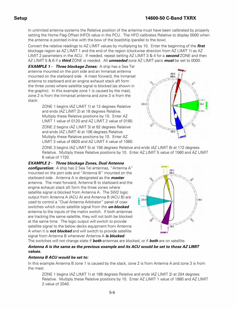
Setup 14600-50 C-Band TXRX
5-6
In unlimited antenna systems the Relative position of the antenna must have been calibrated by properly setting the Home Flag Offset (HFO) value in the PCU. The HFO calibrates Relative to display 0000 when the antenna is pointed in-line with the bow of the boat/ship (parallel to the bow).
Convert the relative readings to AZ LIMIT values by multiplying by 10. Enter the beginning of the first blockage region as AZ LIMIT 1 and the end of the region (clockwise direction from AZ LIMIT 1) as AZ LIMIT 2 parameters in the ACU. If needed, repeat setting AZ LIMIT 3 & 4 for a second ZONE and then AZ LIMIT 5 & 6 if a third ZONE is needed. All unneeded zone AZ LIMIT pairs must be set to 0000.
EXAMPLE 1 - Three blockage Zones: A ship has a Sea Tel antenna mounted on the port side and an Inmarsat antenna mounted on the starboard side. A mast forward, the Inmarsat antenna to starboard and an engine exhaust stack aft form the three zones where satellite signal is blocked (as shown in the graphic). In this example zone 1 is caused by the mast, zone 2 is from the Inmarsat antenna and zone 3 is from the stack:
ZONE 1 begins (AZ LIMIT 1) at 12 degrees Relative and ends (AZ LIMIT 2) at 18 degrees Relative. Multiply these Relative positions by 10. Enter AZ LIMIT 1 value of 0120 and AZ LIMIT 2 value of 0180.
ZONE 2 begins (AZ LIMIT 3) at 82 degrees Relative and ends (AZ LIMIT 4) at 106 degrees Relative. Multiply these Relative positions by 10. Enter AZ LIMIT 3 value of 0820 and AZ LIMIT 4 value of 1060.
ZONE 3 begins (AZ LIMIT 5) at 156 degrees Relative and ends (AZ LIMIT 6) at 172 degrees Relative. Multiply these Relative positions by 10. Enter AZ LIMIT 5 value of 1560 and AZ LIMIT 6 value of 1720.
EXAMPLE 2 - Three blockage Zones, Dual Antenna configuration: A ship has 2 Sea Tel antennas, “Antenna A” mounted on the port side and “Antenna B” mounted on the starboard side. Antenna A is designated as the master antenna. The mast forward, Antenna B to starboard and the engine exhaust stack aft form the three zones where satellite signal is blocked from Antenna A. The SW2 logic output from Antenna A (ACU A) and Antenna B (ACU B) are used to control a “Dual Antenna Arbitrator” panel of coax switches which route satellite signal from the un-blocked antenna to the inputs of the matrix switch. If both antennas are tracking the same satellite, they will not both be blocked at the same time. The logic output will switch to provide satellite signal to the below decks equipment from Antenna A when it is not blocked and will switch to provide satellite signal from Antenna B whenever Antenna A is blocked. The switches will not change state if both antennas are blocked, or if both are on satellite.
Antenna A is the same as the previous example and its ACU would be set to those AZ LIMIT values.
Antenna B ACU would be set to:
In this example Antenna B zone 1 is caused by the stack, zone 2 is from Antenna A and zone 3 is from the mast.
ZONE 1 begins (AZ LIMIT 1) at 188 degrees Relative and ends (AZ LIMIT 2) at 204 degrees Relative. Multiply these Relative positions by 10. Enter AZ LIMIT 1 value of 1880 and AZ LIMIT 2 value of 2040.

14600-50 C-Band TXRX Setup
5-7
ZONE 2 begins (AZ LIMIT 3) at 254 degrees Relative and ends (AZ LIMIT 4) at 278 degrees Relative. Multiply these Relative positions by 10. Enter AZ LIMIT 3 value of 2540 and AZ LIMIT 4 value of 2780.
ZONE 3 begins (AZ LIMIT 5) at 342 degrees Relative and ends (AZ LIMIT 6) at 348 degrees Relative. Multiply these Relative positions by 10. Enter AZ LIMIT 5 value of 3420 and AZ LIMIT 6 value of 3480.
EXAMPLE 3 - One blockage Zone: A ship has a Sea Tel antenna mounted on the center line of the ship. A mast is forward and an engine exhaust stack is aft. In this example the Stack does NOT block the satellite, only the mast forward does. In this example zone 1 is caused by the mast, zone 2 and zone 3 are not needed:
ZONE 1 begins (AZ LIMIT 1) at 352 degrees Relative and ends (AZ LIMIT 2) at 8 degrees Relative. Multiply these Relative positions by 10. Enter AZ LIMIT 1 value of 3520 and AZ LIMIT 2 value of 0080.
ZONE 2 is not needed. Enter AZ LIMIT 3 value of 0000 and AZ LIMIT 4 value of 0000.
ZONE 3 is not needed. Enter AZ LIMIT 5 value of 0000 and AZ LIMIT 6 value of 0000.
5.5. TX Polarity Setup To prevent inadvertent switching of the transmit polarity, the user can lock out NS/EW toggle feature and force the transmit polarity to be fixed horizontal or vertical with the TX POLARITY parameter.
With the feed in the center of its polarization adjustment range, observe the transmit port polarity (vector across the short dimension of the transmit wave-guide).
If the transmit polarity in the center of the travel range is vertical, use the following entries:
2 Vertical Transmit Polarity
4 Horizontal Transmit Polarity
If the Transmit polarity in the center of the travel range is horizontal, use the following entries:
2 Horizontal Transmit Polarity
4 Vertical Transmit Polarity

Setup 14600-50 C-Band TXRX
5-8
5.6. ACU Factory Default Parameter Settings – 14600 Antennas The following table shows the factory default parameters for the ACU interfaced to a 14600 Antenna. You may need to optimize some of these parameters. Refer to the individual parameter setting information in the Setup section of your ACU manual.
PARAMETER C-Band
DishScan
My Parameters
EL TRIM 0
AZ TRIM 0
AUTO THRES 100
EL STEP SIZE 0
AZ STEP SIZE 0
STEP INTEGRAL 0
SEARCH INC 10
SEARCH LIMIT 200
SEARCH DELAY 30
SWEEP INC 0040
SYSTEM TYPE TXRX=5
GYRO TYPE 2
POL TYPE 72
POL OFFSET 30
POL SCALE 90
AZ LIMIT 1 0
AZ LIMIT 2 0
AZ LIMIT 3 0
AZ LIMIT 4 0
AZ LIMIT 5 0
AZ LIMIT 6 0
5V OFFSET 0
5V SCALE 0
TX POLARITY 2 or 4
* Modem Lock input & Modem TX Mute functions are NOT set, refer to SYSTEM TYPE parameter information.
14600-50 C-Band TXRX Functional Testing
6-1
6. Functional Testing If not already ON, Turn ON the Power switch on the front panel of the ACU.
6.1. ACU / Antenna System Check 1. Turn ACU power ON. Turn antenna Pedestal/RF Equipment power ON
2. Press RESET on the ACU front panel of the ACU. Verify the display shows "SEA TEL INC - MASTER" and the ACU software version number. Wait 10 seconds for the display to change to "SEA TEL INC - REMOTE" and the PCU software version number. If the display shows "REMOTE INITIALIZING” wait for approximately 2 minutes for the antenna to complete initialization and report the Antenna Model and PCU software version.
3. Press the Ship, Satellite, Antenna and Status keys repeatedly to display their respective menus. This verifies that the displays change in the correct response to the keys.
If “REMOTE NOT RESPONDING" is displayed, or the displays do not change when the main menu keys are pressed, refer to the Troubleshooting Section of your ACU manual. Return to normal operation OR Continue with the next functional test.
6.2. Latitude/Longitude Auto-Update check This verifies that the GPS antenna input to the system is automatically updating the position information.
1. Press SHIP twice to select the Latitude entry menu. Press the 0 (zero) key on the numeric keypad and then press ENTER. If automatic updating is working properly the Latitude value display will return to the current ships Latitude position within a few seconds.
2. Press SHIP again to select the Longitude entry menu. Press the 0 (zero) key on the numeric keypad and then press ENTER. If automatic updating is working properly the Longitude value display will return to the current ships Longitude position within a few seconds.
If the displays do not update, check your cable connections, assure that the SYSTEM TYPE parameter sum includes the 8 value and then refer to the Troubleshooting Section of this manual for AUX SERIAL PORT checks. Return to normal operation OR Continue with the next functional test.
6.3. Heading Following Verify that the heading display in the ACU is following the ships Gyro Compass.
1. Press SHIP repeatedly until the Heading display is selected. When Left and right values are displayed, left is the response from the pedestal and right in the local input from the gyrocompass.
2. Have another person call out the Gyro Compass heading to you while you observe the Heading display. The Heading display should consistently be exactly the same as the Gyro Compass value. If the heading display changes incorrectly or the red ERROR LED illuminates on the front panel, refer to the Troubleshooting section of the ACU manual.
3. Return to normal operation OR Continue with the next functional test.
If the antenna does not drive properly, refer to the Troubleshooting Section of your ACU manual. Return to normal operation OR Continue with the next functional test.
Functional Testing 14600-50 C-Band TXRX
6-2
6.4. Azimuth & Elevation Drive This verifies that the antenna moves in the correct response to the keys.
1. Press the Antenna key twice to display the Azimuth menu.
2. Press the AUX1 key to toggle Tracking OFF. Press the UP arrow key repeatedly and verify that the antenna moves up in Azimuth.
3. Press the DOWN arrow key repeatedly and verify that the antenna moves down in Azimuth.
4. Press the Antenna key once to display the Elevation menu.
5. Press the UP arrow key repeatedly and verify that the antenna moves up in elevation.
6. Press the DOWN arrow key repeatedly and verify that the antenna moves down in elevation.
6.5. Four Quadrant Test Tracking Four Quadrant Tracking Test is the best way to test tracking (regardless of which tracking mode is being used). This tests each of the 4 quadrants (UP, DOWN, LEFT & RIGHT of peak signal AZ/EL pointing) to assure that the tracking mode being used drives the dish back to peak satellite signal level. Note: Return to peak should take about the same amount of time from each of the four quadrants.
1. Press AUX1 to Turn Tracking OFF. Press ANTENNA twice to select Azimuth entry menu and note current AGC level. Press UP arrow key repeatedly until AGC falls about 100 counts, note current AZ position (You should have moved the antenna 1/3 to ¾ of a degree depending on antenna size and frequency band). Observe the DishScan signaling in the lower left of the display, if the system is operating in DishScan tracking mode the signaling should be 4’s. Press AUX1 to turn tracking ON and verify that the antenna does return to the previous AZ position and the peak AGC level.
2. Press AUX1 to Turn Tracking OFF. Press DOWN arrow key repeatedly until AGC falls about 100 counts, note current AZ position (You should have moved the antenna 1/3 to ¾ of a degree depending on antenna size and frequency band). Observe the DishScan signaling in the lower left of the display, if the system is operating in DishScan tracking mode the signaling should be 6’s. Press AUX1 to turn tracking ON and verify that the antenna does return to the previous AZ position and the peak AGC level.
3. Press AUX1 to Turn Tracking OFF. Press ANTENNA to select Elevation entry menu and note current AGC level. Press UP arrow key repeatedly until AGC falls about 100 counts, note current EL position (You should have moved the antenna 1/3 to ¾ of a degree depending on antenna size and frequency band). Observe the DishScan signaling in the lower left of the display, if the system is operating in DishScan tracking mode the signaling should be 2’s. Press AUX1 to turn tracking ON and verify that the antenna does return to the previous EL position and the peak AGC level.
4. Press AUX1 to Turn Tracking OFF. Press ANTENNA to select Elevation entry menu and note current AGC level. Press DOWN arrow key repeatedly until AGC falls about 100 counts, note current EL position (You should have moved the antenna 1/3 to ¾ of a degree depending on antenna size and frequency band). Observe the DishScan signaling in the lower left of the display, if the system is operating in DishScan tracking mode the signaling should be 8’s. Press AUX1 to turn tracking ON and verify that the antenna does return to the previous EL position and the peak AGC level.
If the antenna does not drive properly or if Tracking does not return the signal to “peak” refer to the Troubleshooting Section of this manual.

14600-50 C-Band TXRX Maintenance and Troubleshooting
7-1
7. Maintenance and Troubleshooting This section describes the theory of operation to aid in troubleshooting and adjustments of the antenna system. Also refer to the Troubleshooting section of your ACU manual for additional troubleshooting details.
WARNING: Electrical Hazard – Dangerous AC Voltages exist inside the Antenna Pedestal Breaker Box. Observe proper safety precautions when working inside the Antenna Pedestal Breaker Box.
WARNING: Electrical Hazard – Dangerous AC Voltages exists on the side of the Antenna Pedestal Power Supply. Observe proper safety precautions when working inside the Antenna Power Supply.
WARNING: RF Radiation Hazard - This stabilized antenna system is designed to be used with transmit/receive equipment manufactured by others. Refer to the documentation supplied by the manufacturer which will describe potential hazards, including exposure to RF radiation, associated with the improper use of the transmit/receive equipment. Note that the transmit/receive equipment will operate independently of the stabilized antenna system.
The ultimate responsibility for safety rests with the facility operator and the individuals who work on the system.
WARNING: RF Radiation Hazard - Prior to working on the stabilized antenna system, the power to the transmit/receive equipment must be locked out and tagged. Turning OFF power to the Antenna Control Unit does NOT turn Transmit power output OFF.
The ultimate responsibility for safety rests with the facility operator and the individuals who work on the system.
WARNING: RF Radiation Hazard - When the transmit/receive system is in operation, no one should be allowed anywhere within the radiated beam being emitted from the reflector.
The ultimate responsibility for safety rests with the facility operator and the individuals who work on the system.
7.1. Warranty Information Sea Tel Inc. supports its Series 96, 97 and 00 systems with a ONE YEAR warranty on parts and labor.
What’s Covered by the Limited Warranty?
The Sea Tel Limited Warranty is applicable for parts and labor coverage to the complete antenna system, including all above-decks equipment (radome, pedestal, antenna, motors, electronics, wiring, etc.) and the Antenna Control Unit (ACU).
What’s NOT Covered by the Limited Warranty?
It does not include Transmit & Receive RF Equipment, Modems, Multiplexers or other distribution equipment, whether or not supplied by Sea Tel commonly used in Satellite Communications (TXRX) Systems. These equipments are covered by the applicable warranties of the respective manufacturers.
Factory refurbished components used to replace systems parts under this warranty are covered by this same warranty as the original equipment for the balance of the original warranty term, or ninety (90) days from the date of replacement, whichever occurs last. Original Installation of the Series 97 system must

Maintenance and Troubleshooting 14600-50 C-Band TXRX
7-2
be accomplished by or under the supervision of an authorized Sea Tel dealer for the Sea Tel Limited Warranty to be valid and in force.
Should technical assistance be required to repair your system, the first contact should be to the agent/dealer you purchased the equipment from.
Please refer to the complete warranty information included with your system.
7.2. Recommended Preventive Maintenance Ensure that all of the normal operating settings (LAT, LON, HDG, SAT and al of the Tracking Receiver settings) are set correctly. Refer to the Functional Testing section to test the system.
7.2.1. Check ACU Parameters Assure that the parameters are set correctly (you may wish to record them in the Factory Default Settings, in section 5 of this manual).
7.2.2. Latitude/Longitude Auto-Update check Refer to the Latitude & Longitude Update check procedure in the Functional Testing section of this manual.
7.2.3. Heading Following Refer to the Heading Following verification procedure in the Functional Testing section of this manual.
7.2.4. Azimuth & Elevation Drive Refer to the Azimuth & Elevation Drive check procedure in the Functional Testing section of this manual.
7.2.5. Test Tracking Refer to the four quadrant Tracking check procedure in the Functional Testing section of this manual.
7.2.6. Visual Inspection - Radome & Pedestal Conduct a good, thorough, visual inspection of the radome and antenna pedestal. Visually inspect the inside surface of the radome top and of the antenna pedestal. Look for water or condensation, rust or corrosion, white fiberglass powder residue, loose wiring connections, loose hardware, loose or broken belts or any other signs of wear or damage.
1. Radome Inspection - All the radome flanges are properly sealed to prevent wind, saltwater spray and rain from being able to enter the radome. Re-seal any open (“leaky”) areas with marine approved silicone sealant. If heavy condensation, or standing water, is found inside the radome, isolate and seal the leak, and then dry out the radome. Small (1/8 inch) holes may be drilled in the base pan of the radome to allow standing water to “weep” out.
2. Antenna Pedestal Inspection - The shock/vibration springs and/or wire rope Isolators should not be frayed, completely compressed, or otherwise damaged. The plated and painted parts should not be rusted or corroded. The harnesses should not be frayed and all the connectors should be properly fastened and tightened. All hardware should be tight (no loose assemblies or counter-weights). Replace, re-coat, repair and/or tighten as necessary.

14600-50 C-Band TXRX Maintenance and Troubleshooting
7-3
7.2.7. Mechanical Checks Turn the pedestal power supply OFF
1. Inspect inside of radome for signs that the dish or feed have been rubbing against the inside of the fiberglass radome.
2. Rotate the pedestal through its full range of azimuth motion. The antenna should rotate freely and easily with light finger pressure.
3. Rotate the pedestal through full range of elevation rotation. The antenna should rotate freely and easily with light finger pressure.
4. Rotate the pedestal through full range of cross-level rotation. The antenna should rotate freely and easily with light finger pressure.
5. Rotate the level cage through the full 90 degrees of rotation from CCW stop to CW stop. The level cage antenna should rotate freely and easily with light finger pressure. Attached cables should not cause the cage to spring back more that a few degrees from either stop when released.
6. Inspect all drive belts for wear (black dust on/under the area of the belt).
7. Inspect AZ Drive chain. IF chain is beginning to show signs of rust or corrosion, apply a light coat of light duty oil to the chain. Wipe excess oil off to leave a light coating on the chain. DO NOT over-lubricate.
7.2.8. Check Balance Check the balance of the antenna, re-balance as needed (refer to the Balancing the Antenna procedure below).
7.2.9. Observe Antenna Initialization Observe the Antenna Initialization as described in the Troubleshooting section below.
7.3. Troubleshooting Below are theory and diagnostic tests to assist you with troubleshooting the antenna. Refer to the previous section to check settings and do some initial functional testing prior to beginning troubleshooting.
7.3.1. Theory Of Stabilization Operation The antenna system is mounted on a three axis stabilization assembly that provides free motion with 3 degrees of freedom. This assembly allows the inertia of the antenna system to hold the antenna pointed motionless in inertial space while the ship rolls, pitches and yaws beneath the assembly. Three low friction torque motors attached to each of the three free axes of the assembly provide the required force to overcome the disturbing torque imposed on the antenna system by cable restraints, bearing friction and small air currents within the radome. These motors are also used to re-position the antenna in azimuth and elevation.
The Pedestal Control Unit (PCU) uses inputs from the level cage sensors to calculate the amount of torque required in each axis to keep the antenna pointed within +/-0.2 degrees. The basic control loops for Cross Level, Level and Azimuth are shown in the Control Loop Diagram, drawing 116287. The primary sensor input for each loop is the rate sensor mounted in the Level Cage Assembly. This sensor reports all motion of the antenna to the PCU. The PCU immediately responds by applying a torque in the opposite direction to the disturbance to bring the antenna back to its desired position. Both the instantaneous output of the rate sensor

Maintenance and Troubleshooting 14600-50 C-Band TXRX
7-4
(Velocity Error) and the integrated output of the rate sensor (Position Error) are used to achieve the high pointing accuracy specification.
The calculated torque commands are converted to a 5 volt differential analog signal by a Digital to Analog converter (D/A) and sent to each of three Brush-Less Servo Amplifiers. These amplifiers provide the proper drive polarities and commutation required to operate the Brush-Less DC Servo Motors in torque mode. The Torque acting on the mass of the antenna cause it to move, restoring the rate sensors to their original position, and closing the control loop.
Since the rate sensors only monitor motion and not absolute position, a second input is required in each axis as a long term reference to keep the antenna from slowly drifting in position. The Level and Cross Level reference is provided by a two axis tilt sensor in the level cage assembly. The Azimuth reference is provided by combining the ships gyro compass input and the antenna relative position.
7.3.2. Antenna Initialization (Series 97A & Series 00 ) Turn the pedestal power supply ON. The PCU will initialize the stabilized portion of the mass to be level with the horizon and at a prescribed Azimuth and Elevation angles. The antenna will go through the specific sequence of steps (listed below) to initialize the level cage, elevation, cross-level and azimuth to predetermined starting positions.
Initialization is completed in the following phases, each phase must complete properly for the antenna to operate properly (post-initialization). Observe the Initialization of the antenna pedestal.
Step 1. The level platform motor drives the Level Cage CW, issuing extra steps to assure that the cage is all the way to the mechanical stop. Then the Level Cage will be driven exactly 45.0 degrees CCW.
Step 2. Elevation axis then activates - Input from the LV axis of the tilt sensor is used to drive the Elevation of the equipment frame to bring the tilt sensor LV axis to level. This step takes approximately 10 seconds and will result in the dish being at 45.0 degrees in elevation. The level cage may still be tilted left or right at this time.
Step 3. Cross-Level axis activates - Input from the CL axis of the tilt sensor is used to drive Cross-Level of the equipment frame to bring the cross-level axis of the tilt sensor to level (this results in the tilt of the Cross-Level Beam being level). This step takes approximately 10 seconds.
Step 4. Azimuth axis activates - Antenna drives CW in azimuth until the “Home Flag” signal is produced. This signal is produced by a Home Switch hitting a cam (or by a Hall Effect sensor in close proximity to a Magnet). After another 10 second wait, the antenna will report its version number at the Antenna Control Unit (ACU).
This completes the phases of initialization. At this time the antenna elevation should 45.0 degrees and Relative azimuth should be at home flag (home switch engaged on the home flag cam).
If any of these steps fail, or the ACU reports model "xx97", re-configure the PCU as described in the Setup section of this manual. If initialization still fails, this indicates a drive or sensor problem, refer to the Troubleshooting section.
7.3.3. Antenna Position Error Monitoring The ACU provides a means for monitoring the position error of the antenna for diagnostic purposes. If this error is excessive, it indicates external forces are acting on the antenna. These forces may be the result of static imbalance, excessive bearing friction, cable binding, or wind loading.
To view the position error, select the REMOTE COMMAND window on the ACU:

14600-50 C-Band TXRX Maintenance and Troubleshooting
7-5
1. Key in ".120 ENTER" (note the decimal point). "x0000" should appear in the command window.
2. Press the MODE key once more to display the REMOTE MONITOR window. The lower display will show "iv" and three 4 digit hex numbers (iv FFFF 0001 FFFD).
The numbers indicate Cross Level, Level and Azimuth errors at a resolution of 1 part in 65536 or 0.0055 degrees. For example a display like "iv FFFF 0001 FFFD" indicates the Cross Level error is -0.005 degrees, the Level error is + 0.005 degrees and the Azimuth error is -0.016 degrees. The normal range of these numbers is FFF0 to 000F and they typically will bounce around randomly within this range.
7.3.4. Open Loop Rate Sensor Test The ACU provides a means for monitoring the output of the 3 solid state rate sensors and the 3 reference sensors for diagnostic purposes. The rate sensors and reference sensors are the primary inputs to the PCU for stabilization.
To monitor the rate sensors, select the REMOTE COMMAND window on the ACU:
1. Key in ".119 ENTER" (note the decimal point). "w0000" should appear in the command window.
2. Press the MODE key once more to display the REMOTE MONITOR window. The lower display will show "w" and three 4 digit decimal numbers (w 1111 2222 3333) .
The numbers represent the Cross Level, Level and Azimuth rate sensor outputs respectively each having a nominal display of 2048. The display values will change during movement and return to nominal when movement stops.
The Cross Level display should decrease when the antenna is tilted to the left and increase when tilted to the right.
The Level display should decrease when the antenna is tilted forward and increase when tilted back.
The Azimuth display should decrease when rotated CCW and increase when rotated CW.
7.3.5. Open Loop Rate Sensor Test The ACU provides a means for monitoring the output of the 3 solid state rate sensors and the 3 reference sensors for diagnostic purposes. The rate sensors and reference sensors are the primary inputs to the PCU for stabilization.
To monitor the rate sensors, select the REMOTE COMMAND window on the ACU:
1. Key in ".119 ENTER" (note the decimal point). "w0000" should appear in the command window.
2. Press the MODE key once more to display the REMOTE MONITOR window. The lower display will show "w" and three 4 digit decimal numbers (w 1111 2222 3333) .
The numbers represent the Cross Level, Level and Azimuth rate sensor outputs respectively each having a nominal display of 2048. The display values will change during movement and return to nominal when movement stops.
The Cross Level display should decrease when the antenna is tilted to the left and increase when tilted to the right.
The Level display should decrease when the antenna is tilted forward and increase when tilted back.
The Azimuth display should decrease when rotated CCW and increase when rotated CW.

Maintenance and Troubleshooting 14600-50 C-Band TXRX
7-6
7.3.6. Open Loop Motor Test The ACU provides a means for driving each individual torque motor to test that motors functionality. By driving each axis and observing the resulting motion of the antenna, a coarse operational status of the motor and motor driver can be established.
To manually drive the motors, select the REMOTE COMMAND window on the ACU:
1. Key in ".94 ENTER" (note the decimal point). "^0000" should appear in the command window.
2. To drive the Cross Level motor, key in 1064, 1128 or 1192 to drive the Cross Level axis LEFT, OFF or RIGHT respectively.
3. To drive the Level motor, key in 2064, 2128 or 2192 to drive the level axis FORWARD, OFF or BACKWARD respectively.
4. To drive the Azimuth motor, key in 3064, 3128 or 3192 to drive the azimuth axis CW, OFF or CCW.
7.3.7. To Disable/Enable DishScan To toggle the ON/OFF state of DishScan, select the remote parameter DISHSCAN. This remote parameter allows you to view, or change, the DishScan ON/OFF status.
1. Press UP arrow and ENTER to turn DishScan ON.
2. Press DOWN arrow and ENTER to turn DishScan OFF.
3. If you change this remote parameter, you must save the change using REMOTE PARAMETERS.
If DishScan is OFF and the Step Integral parameter is set to 0000, you will get a constant ERROR 0016 (DishScan error) and you will see zeros flashing in the lower left of the Azimuth and Elevation ENTRY menu displays. This is a visual indication that DishScan is turned OFF.
7.3.8. Satellite Reference Mode The ships gyro compass input to the ACU may be accurate and stable in static conditions and yet may NOT be accurate or stable enough in some underway dynamic conditions. If there is no gyro compass or if the input is corrupt, not stable or not consistently accurate the tracking errors will become large enough to cause the antenna to be mis-pointed off satellite.
Satellite Reference Mode will uncouple the gyro reference from the azimuth rate sensor control loop. When operating in Satellite Reference Mode changes in ships gyro reading will not directly affect the azimuth control loop. The Pedestal Control Unit will stabilize the antenna based entirely on the azimuth rate sensor loop and the tracking information from DishScan. This will keep the azimuth rate sensor position from eventually drifting away at a rate faster than the tracking loop can correct by using the tracking errors to regulate the rate sensor bias.
Satellite Reference Mode can be used as a diagnostic mode to determine if tracking errors are caused by faulty gyro inputs.
Satellite Reference Mode MUST be used when:
• No Gyro Compass is available
• Frequent or constant ACU Error Code 0001 (Gyro Compass has failed)
• Gyro Compass output is NMEA heading
• Flux Gate Compass is being used
• GPS Satellite Compass is being used
To view, or change, the Satellite Reference Mode status, select the SAT REF remote parameter:
4. Press UP arrow and then the ENTER key to turn Satellite Reference Mode ON.
5. Press DOWN arrow and then the ENTER key to turn Satellite Reference Mode OFF.

14600-50 C-Band TXRX Maintenance and Troubleshooting
7-7
If you change this remote parameter, you must save the change using REMOTE PARAMETERS.
7.3.9. To Read/Decode an ACU Error Code 0008 (Pedestal Error): Select the REMOTE COMMAND window on the ACU and;
1. Key in .83 and then hit the ENTER key (note the decimal point). "S0000" should appear in the command window.
2. Press MODE, or ENTER, to go to REMOTE MONITOR window. SABC@ will be displayed (S followed by 3 letters and a symbol (checksum). The fourth letter (C above) is the pedestal error letter. Ref is an AZ Reference, encoder or Home Flag error. AZ is Azimuth, LV is Level (Elevation) and CL is Cross-Level. Decode the letter code using the chart below:
Letter REF AZ LV CL Description of Pedestal Error
@ 0 0 0 0 None
A 0 0 0 1 CL
B 0 0 1 0 LV
C 0 0 1 1 CL + LV
D 0 1 0 0 AZ
E 0 1 0 1 AZ + CL
F 0 1 1 0 AZ + LV
G 0 1 1 1 AZ + LV + CL
H 1 0 0 0 Ref
I 1 0 0 1 Ref + CL
J 1 0 1 0 Ref + LV
K 1 0 1 1 Ref + LV + CL
L 1 1 0 0 Ref + AZ
M 1 1 0 1 Ref + AZ + CL
N 1 1 1 0 Ref + AZ + LV
O 1 1 1 1 Ref + AZ + LV + CL
P 0 0 0 0 Stab Limit
Q 0 0 0 1 Stab Limit + CL
R 0 0 1 0 Stab Limit + LV
S 0 0 1 1 Stab Limit + CL + LV
T 0 1 0 0 Stab Limit + AZ
U 0 1 0 1 Stab Limit + AZ + CL
V 0 1 1 0 Stab Limit + AZ + LV
W 0 1 1 1 Stab Limit + AZ + LV + CL
X 1 0 0 0 Stab Limit + Ref
Y 1 0 0 1 Stab Limit + Ref + CL
Z 1 0 1 0 Stab Limit + Ref + LV
[ 1 0 1 1 Stab Limit + Ref + LV + CL

Maintenance and Troubleshooting 14600-50 C-Band TXRX
7-8
\ 1 1 0 0 Stab Limit + Ref + AZ
] 1 1 0 1 Stab Limit + Ref + AZ + CL
^ 1 1 1 0 Stab Limit + Ref + AZ + LV
_ 1 1 1 1 Stab Limit + Ref + AZ + LV + CL
7.3.10. Get Remote GPS LAT/LON Position: The remote command in the DAC-03 to get the position from the GPS antenna mounted on the antenna pedestal:
1. Select the REMOTE COMMAND window on the ACU and;
2. Key in ".64 ENTER" (note the decimal point). "@0000" should appear in the command window.
3. Press the MODE key once more to display the REMOTE MONITOR window. The lower display will show "@" and the Latitude and Longitude string, such as @3800,N,12202,W,A^ for the location of the Sea Tel factory.
The Latitude & Longitude position of the GPS will be displayed in the following format:
@ LAT,N,LON,E,A & where LAT and LON are in degrees and minutes, LAT will be followed by N or S (North or South), LON will be followed by E or W (East or West), then a status character and finally a checksum character. Furuno default value is in Japan at 34.4N 135.2E (@3444,N,13521,E,,_). After acquiring a good fix at Sea Tel the string is @3800,N,12202,W,A^ for our 38N 122W Latitude and Longitude position.
The status character tells you the status of the GPS.
• Comma = GPS has NOT acquired a fix, OR
• N = GPS fix is NOT valid OR
• A = GPS has acquired a valid fix.
As a test, if a valid fix is being viewed in the Remote Monitor window and the GPS antenna cable is unplugged from the PCU, the status character which was an A should become an N within 5 seconds.
7.4. Maintenance
7.4.1. Balancing the Antenna The antenna and equipment frame are balanced at the factory however, after disassembly for shipping or maintenance, balance adjustment may be necessary. Balancing must be done with the power supply turned OFF. No belt removal is required to balance the antenna pedestal. Balancing is accomplished by adding or removing balance trim weights at strategic locations to keep the antenna from falling forward/backward or side to side. The antenna system is not pendulous so 'balanced' is defined as the antenna remaining at rest when left in any position. The antenna should be balanced within one or two ounces at the typical trim weight location of 2 feet from the axis of rotation.
The recommend balancing order is Elevation Axis with the antenna pointed at the horizon (referred to as front to back balance). Elevation Axis with the antenna pointed at zenith (referred to as top to bottom balance). Then Cross Level axis at any elevation position (referred to as side to side balance). The balance about azimuth axis is accomplished by accurately positioning the cross level beam in the azimuth stabilization assembly. This adjustment is done at the factory using special alignment tools. Do NOT attempt to adjust the cross level beam position in the field without the proper test fixtures.

14600-50 C-Band TXRX Maintenance and Troubleshooting
7-9
7.4.2. To Adjust Tilt: Select the REMOTE TILT window on the ACU and;
1. While at the Remote Tilt window, press the UP arrow.
2. Set a bubble (or bulls-eye) level on top of the Level Cage assembly.
3. Press the number 5 to zero the tilt sensor bias. NOTE: If the level cage is not within 4 degrees of level fore/aft or left/right, replace the Level Cage assembly.
4. If the level cage is within 4 degrees, use the 2 and 8 key to adjust LV (fore/aft) until the level cage is level in this axis.
5. If the level cage is within 4 degrees, use the 4 and 6 key to adjust CL (left/right) until the level cage is level in this axis.
6. Once the level cage is level in both axes, wait for 30 seconds then press the DOWN arrow key and then press the ENTER key.
7. Press MODE (or ENTER) to step the menu to REMOTE PARAMETERS.
8. Press the UP arrow key and then press the ENTER key to save the settings in the PCU.
This save the new tilt bias settings in the PCU. Reset or re-initialize the antenna to verify that the Level cage is properly level with the new settings.
7.4.3. To Reset/Reinitialize the Antenna: Select the REMOTE COMMAND window on the ACU and;
1. Key in .94 and then hit the ENTER key (note the decimal point) to access the utility commands. "^0000" should appear in the command window.
2. Key in 90 and then hit the ENTER key.
This resets the PCU on the antenna. The antenna will reinitialize with this command (Performs a similar function as a power reset of the antenna).
7.5. Pedestal Control Unit Configuration (xx97A & xx00) The PCU is designed to be used with a variety of antenna pedestal configurations. The configuration information that is unique to each pedestal type is stored in a Non Volatile Random Access Memory (NVRAM) in the PCU enclosure. If the PCU is replaced or the NVRAM in the PCU should become corrupt, the PCU must be re-configured to operate with the pedestal it is installed on. The default configuration for the PCU is model xx97A. In this configuration the PCU will not drive any of the three torque motors (AZ, EL & CL) to prevent damage to the unknown pedestal.
Visually confirm the PCU software version to identify the correct system configuration number to use for your antenna. Press the RESET button on your ACU to display the Antenna Control Unit software version and then, about 10 seconds later, the PCU model and software version will be displayed.
To configure the PCU, select the REMOTE COMMAND window on the DAC-97/DAC-03 by pressing the MODE key until this window appears (if the DAC-97/DAC-03 will not advance beyond the REMOTE AUX window, enter 7979 and press ENTER).
EXAMPLE: For an 9797A Model Antenna with PCU software version 2.00:
5. In the REMOTE COMMAND window, key in ". 7 8 ENTER". An "N" should now appear in the command window.
6. Refer to the tables below to find the appropriate value for your PCU software and your model antenna. In this case, refer to the software version 2.xx list below to find 9797A is configuration number "0211"
7. Key in "0211" to select system type 211. The REMOTE COMMAND display should now show "N0211".

Maintenance and Troubleshooting 14600-50 C-Band TXRX
7-10
8. Press ENTER to send this system type command to the PCU.
9. Press ENTER several times to select REMOTE PARAMETERS. Press UP arrow and then ENTER to save the system type in the PCU.
10. Press ANTENNA, MODE, N/S to display the Remote Version Number. It should now display "9797A VER 2.nn".
7.5.1. If your PCU software version is 1.5x: Your model configuration numbers are:
MODEL Configuration Number
xx97 N 0000 Turns off all drive motors
9797A N 0208
8797A N 0209
9997A N 0210
8897A N 0211
12097A N 0212
14497A N 0213
14600 N 0214
9497A N 0215
9697A N 0216
14400 N 0217
7.5.2. If your PCU software version is 2.xx: Your model configuration numbers are:
MODEL Configuration Number
xx97 N 0000 Turns off all drive motors
8897A N 0205
9497A N 0206
12097A N 0207
14400 N 0208
8797A N 0209
9697A N 0210
9797A N 0211
14600 N 0212

14600-50 C-Band TXRX Maintenance and Troubleshooting
7-11
7.6. Antenna Stowing Procedure
WARNING: Antenna Pedestal must be properly restrained (stowed) to prevent damage to wire rope isolators, isolator springs and/or antenna pedestal mechanism during underway conditions when power is removed from the antenna assembly.
The normal operating condition for the Sea Tel Antenna system is to remain powered up at all times. This ensures that the antenna remains actively stabilized to prevent physical damage to the antenna pedestal and reduce condensation and moisture in the radome to prevent corrosion. If, for some reason, the antenna must be powered down during underway transits, it should be secured with nylon straps regardless of sea conditions to prevent damage to the antenna system. Refer to the procedure below to secure the antenna pedestal.
Equipment & Hardware needed:
• Two (2) ½-13 x 2-inch Stainless Steel bolts.
• Two (2) Nylon straps with ratchet mechanism. Nylon straps must be rated to 300 lbs. Working load capacity and 900 lbs. Max rated capacity.
Stowing procedure:
1. Point the antenna to Zenith, (90 degree elevation angle), straight up.
2. Install one (1) ½-13 x 2-inch bolt into the inside of each elevation beam as shown in Figure 1.

Maintenance and Troubleshooting 14600-50 C-Band TXRX
7-12
3. Hook one end hook of the nylon strap to bolt in elevation beam as shown in Figure 2.
4. Hook the other end hook of the nylon strap to the pedestal-mounting frame as shown in Figure 3.
5. Use the ratchet of the strap to tighten nylon straps.
As the straps are tightened, observe the vertical isolation canister assembly as shown in Figure 4.
6. Tighten straps until the canister has been pulled down approx. ¼ to ½ inch. Do not over-tighten. You must leave approximately 1/8 inch clearance between the rubber stops and the azimuth driven sprocket to allow the vertical vibration isolation to function properly.
NOTE: Remove both the straps and the bolts before applying power and returning the antenna to normal operating condition.

14600-50 C-Band TXRX Maintenance and Troubleshooting
7-13
7.7. Switching Active/Standby RF Equipment
Warning: For Safety reasons, the maximum current drawn through the AC Power Ring must not exceed 15 Amps. Do NOT allow both amplifiers to be left in the online state. The power ring assembly will be damaged over time. Limit the amount of time that both amplifiers are in the online state to periods of less than 5 minutes.
Warning: The output of the SECONDARY RF equipment is routed into a 50 ohm waveguide terminator. This device is not a “dummy load” that is able to dissipate sustained RF power. If both amplifiers are left in the online state, the 50 ohm terminator will be damaged.
7.7.1. Simplified Block Diagrams: Refer to the Block diagrams below for the Below Decks Equipment (BDE) and the Above Decks Equipment (ADE).
RADIO M&C
DAC-03 ANTENACONTROL UNIT
SERIAL RS-232REMOTE
SATELLITEMODEM
Tx IF
Rx IF
BNCCFE
DC AND RS-422
AUX M&CPC TERMINAL9-PIN
D-SUBCOM PORT
RS-232
D-SUB9-PIN
COM PORT
SHIPSCOMPASS
REFERENCE
ACU M&C
DC AND RS-232
L BAND RX/IF
70 / 140 MHz RX/IF
70 / 140 MHz TX/IF
GPS DATA
RF M&CCOM PORT
9-PIND-SUB
AUX M&C RS-232
J1PEDESTALM&C
ASPAJ11
F
RECEIVER
L BAND
NMEAGPS/HDT
J13
SBS/SYNCHRO
J2
GYROSPLIT FSK
SMA BASE
MODEM
1 MHz
SMA
MUX -2
FSKSPLIT
SMA BASEMUX -2
MODEM
1 MHz
9-PIND-SUB
D-SUB9-PIN
SMA
N
SMA
N
DC
SMAF
F
SPLIT FSK
SMA BASE
MODEM
1 MHz
SMA
MUX -4
9-PIND-SUB
BNC
F
FF TO SPECTRUM
ANALYZER
SPLI
TTER
F
FF
BNC
BNC
BNC
BNC
BNC
BNC
BNC
BNC
TO SPECTRUM ANALYZER
TO SPECTRUM ANALYZER
SWIT
CH
Figure 7-1 BDE Block Diagram

Maintenance and Troubleshooting 14600-50 C-Band TXRX
7-14
Figure 7-2 ADE Block Diagram
7.7.2. Transmit Signal Path The transmit intermediate frequency signal (TXIF), 70MHz ±18Mhz or 140MHz ±36Mhz, comes out of the satellite modem switch and is fed into the DC to 200 port on the 4 channel FSK base modem and is combined with the Codan Monitor and Control (M&C) signals at 1.5 & 1.1 MHz. The output is connected to the DC to 200 input port of the 3 channel FSK base modem where it is combined with the Paradise Datacom M&C signals at 700 KHz & 1.9 MHz. The combined

14600-50 C-Band TXRX Maintenance and Troubleshooting
7-15
output from these base modems is sent to the ADE via the antenna TXIF coax cable to the above deck equipment.
The TXIF cable enters the radome through strain relief grommets at the base of the radome and then connects to a connector bracket at the base of the pedestal. The TXIF signal passes trough the center channel of the dual channel coaxial rotary joint, through the 3 channel FSK pedestal modem, through the 4 channel FSK pedestal modem, through a high pass filter (to block signals below 50 MHz) to a splitter that feeds signal into the TX Input of both Codan Converters.
The online Codan transceiver up-converts to the TXIF signal to the transmit RF output frequency and feeds it to the RF Input of the online Paradise Datacom HPA for amplification (Codan Converter 1 is connected directly to Paradise Datacom HPA 1 and Codan Converter 2 is connected directly to Paradise Datacom HPA 2). The HPA1’s waveguide output is connected to the left input port of the waveguide Baseball switch and HPA2’s waveguide output is connected to the right input port. The waveguide Baseball switch output (top) port is connected to the antenna feed assembly and its’ bottom port has a 120 Watt dummy load attached to it. The RF Equipment and the waveguide baseball switch are controlled from the BDE Computer using the Alphawave and Newpoint software.
7.7.3. Receive Signal Path The waveguide RX output from the feed is routed by a baseball waveguide switch to the desired LNA (controlled from the ACU Tracking – RX/TX routing selection). The receive signal from the LNA is directed in to a splitter network that feeds the RXRF Input of both Codan converters and a C-Band LNB.
Each Codan converter down-converts the RXRF to the Receive Intermediate Frequency (RXIF is at 70 or 140 MHz). The RXIF outputs of the Codan converters are connected to a coax switch used to select which converters’ receive output is routed to the DC to 200 port on the 4 channel FSK pedestal modem in the Receive path. The LNB output is connected directly to the L-Band port on the 4 channel FSK pedestal modem. The 4 channel FSK pedestal modem multiplexes the selected RXIF (70 or 140 MHz), the receive L-Band (950-1450 MHz) and the Pedestal M&C (antenna control) together.
The combined output is connected through the outer channel of the dual channel coax rotary joint to the Receive base 4 channel FSK modem via the Receive coax cable. The combined signals are separated by the 4 channel FSK base modem. The RXIF (70 or 140 MHz) output is routed through a splitter to the RX Input on both Satellite Modems, a spectrum analyzer and possibly the Tracking Receiver in the Antenna Control Unit IF the ACU has a 70, or 140, MHz receiver installed inside it. If the Antenna Control Unit has an L-Band Tracking Receiver installed inside it the L-Band signal from the 4 channel FSK base modems must be connected to a coax switch which is wire to the terminal mounting strip. This coax switch is also controlled by the ACU when you change your receive signal path and selects which of the two receive inputs gets routed to the ACU tracking RF Input. The Pedestal M&C signal is connected to J1 on the rear panel of the ACU.
7.7.4. Codan Converter Monitor and Control (M&C) Signal Paths The packet mode RS-232 Codan M&C signals pass from the BDE computer through the data port of the 4 channel FSK base modem and are modulated at 1.5 MHz (Base TX) and demodulated at 1.1 MHz (Pedestal TX). The M&C signals are combined with the TXIF signal (70 or 140 MHz) and pass though the 3 channel FSK base modem where the Paradise Datacom M&C signals are added to form the complete set of signals that pass up the TXIF coax cable, through the center channel of the dual channel rotary joint to the pedestal MUXs. At the 4 channel FSK pedestal modem the Codan M&C signals are demodulated at 1.5 MHz and modulated at 1.1 MHz and are the RS-485 communications from the modem data port is connected to both Codan Converters via a RS-485 bus assembly.

Maintenance and Troubleshooting 14600-50 C-Band TXRX
7-16
7.7.5. Paradise Datacom HPA Monitor and Control (M&C) Signal Paths The addressed RS-232 Paradise Datacom M&C signals pass from the BDE computer through the data port of the 3 channel FSK base modem and are modulated at 700 KHz and demodulated at 1.9 MHz. The Paradise Datacom M&C signals are combined with the Codan M&C signals and the TXIF signal (70 or 140 MHz) and pass up the TXIF coax cable, through the center channel of the dual channel rotary joint to the pedestal MUXs. At the 3 channel FSK pedestal modem the Paradise Datacom M&C signals are demodulated at 700 KHz and modulated at 1.9 MHz and are the RS-485 communications from the modem data port is connected to both Paradise Datacom HPAs via a RS-485 bus assembly.
7.7.6. RF Equipment Physical Configuration
The RF Equipment that is on the left side of the pedestal is assigned as Side One/Primary.
The RF Equipment that is on the right side of the pedestal is assigned as Side Two/Secondary.
The RF Equipment will be set-up and configured per this physical assignment.
7.7.7. Codan Equipment Set-up Refer to section 6 of the Codan Manual.
Codan LNA Power - Codan Converter 1 must have LNA DC power disabled while Codan Converter 2 must have LNA DC power enabled. The LNA Alarm on both Converters must be disabled to prevent false alarms.
Both units must be set to RS-422 packet mode. The Codan Com Port settings are 9600, 8 and none. Set Converter 1 address to ONE and Converter 2 address to TWO.
Both Codan converters need the FAN Alarm and the SSPA Alarm muted. The temperature settings need to be set to Codan stand alone default.
Set the dip switches on the Codan Converters per the below diagrams. Further configuration will be done through software once communication has been established.
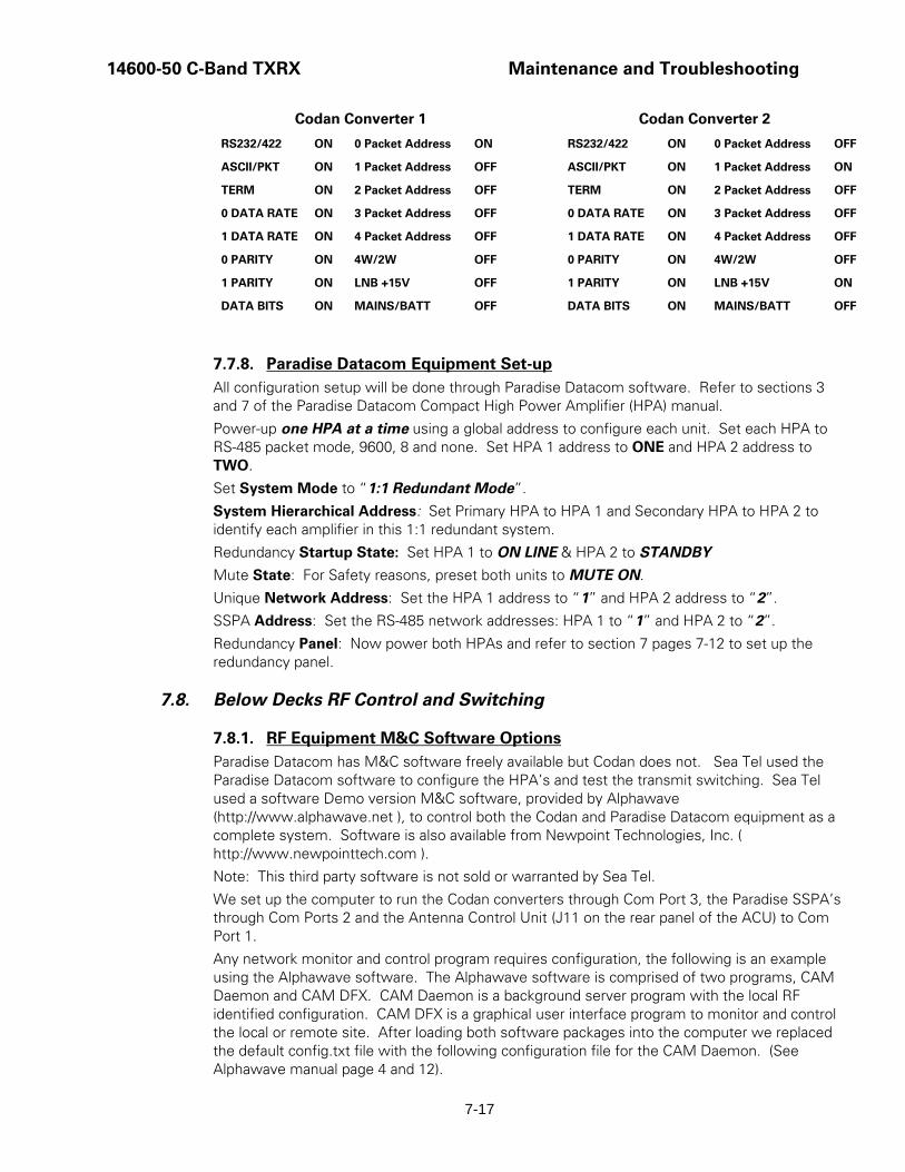
14600-50 C-Band TXRX Maintenance and Troubleshooting
7-17
Codan Converter 1 Codan Converter 2
RS232/422 ON 0 Packet Address ON RS232/422 ON 0 Packet Address OFF
ASCII/PKT ON 1 Packet Address OFF ASCII/PKT ON 1 Packet Address ON
TERM ON 2 Packet Address OFF TERM ON 2 Packet Address OFF
0 DATA RATE ON 3 Packet Address OFF 0 DATA RATE ON 3 Packet Address OFF
1 DATA RATE ON 4 Packet Address OFF 1 DATA RATE ON 4 Packet Address OFF
0 PARITY ON 4W/2W OFF 0 PARITY ON 4W/2W OFF
1 PARITY ON LNB +15V OFF 1 PARITY ON LNB +15V ON
DATA BITS ON MAINS/BATT OFF DATA BITS ON MAINS/BATT OFF
7.7.8. Paradise Datacom Equipment Set-up All configuration setup will be done through Paradise Datacom software. Refer to sections 3 and 7 of the Paradise Datacom Compact High Power Amplifier (HPA) manual.
Power-up one HPA at a time using a global address to configure each unit. Set each HPA to RS-485 packet mode, 9600, 8 and none. Set HPA 1 address to ONE and HPA 2 address to TWO.
Set System Mode to “1:1 Redundant Mode”.
System Hierarchical Address: Set Primary HPA to HPA 1 and Secondary HPA to HPA 2 to identify each amplifier in this 1:1 redundant system.
Redundancy Startup State: Set HPA 1 to ON LINE & HPA 2 to STANDBY
Mute State: For Safety reasons, preset both units to MUTE ON.
Unique Network Address: Set the HPA 1 address to “1” and HPA 2 address to “2”.
SSPA Address: Set the RS-485 network addresses: HPA 1 to “1” and HPA 2 to “2”.
Redundancy Panel: Now power both HPAs and refer to section 7 pages 7-12 to set up the redundancy panel.
7.8. Below Decks RF Control and Switching
7.8.1. RF Equipment M&C Software Options Paradise Datacom has M&C software freely available but Codan does not. Sea Tel used the Paradise Datacom software to configure the HPA’s and test the transmit switching. Sea Tel used a software Demo version M&C software, provided by Alphawave (http://www.alphawave.net ), to control both the Codan and Paradise Datacom equipment as a complete system. Software is also available from Newpoint Technologies, Inc. ( http://www.newpointtech.com ).
Note: This third party software is not sold or warranted by Sea Tel.
We set up the computer to run the Codan converters through Com Port 3, the Paradise SSPA’s through Com Ports 2 and the Antenna Control Unit (J11 on the rear panel of the ACU) to Com Port 1.
Any network monitor and control program requires configuration, the following is an example using the Alphawave software. The Alphawave software is comprised of two programs, CAM Daemon and CAM DFX. CAM Daemon is a background server program with the local RF identified configuration. CAM DFX is a graphical user interface program to monitor and control the local or remote site. After loading both software packages into the computer we replaced the default config.txt file with the following configuration file for the CAM Daemon. (See Alphawave manual page 4 and 12).

Maintenance and Troubleshooting 14600-50 C-Band TXRX
7-18
Config file; =========== define Codan 5000 full_device_type Codan 5700/5900 series Transceiver full_name TRANSCEIVER 1 name CODAN 1 port_flowcontrol NRd port_format 8N1 port_name COM3 port_number 2 port_speed 9600 ; ---------------------------------------- define Codan 5000 full_device_type Codan 5700/5900 series Transceiver full_name TRANSCEIVER 2 name CODAN 2 port_flowcontrol NRd port_format 8N1 port_name COM3 port_number 2 port_speed 9600 ; ---------------------------------------- define CSSPA full_device_type Paradise CSSPA name HPA 1 full_name PARADISE 1 ;-------------------------------- port_name COM2 port_number 2 port_speed 9600 port_format 8N1 port_flowcontrol ND ;-------------------------------- define CSSPA full_device_type Paradise CSSPA name HPA 2 full_name PARADISE 2 ;-------------------------------- port_name COM2 port_number 2 port_speed 9600 port_format 8N1 port_flowcontrol ND ;-------------------------------- define Site full_name CAM Default site location 1 name CAM network 1 ;---------------------------------------------------------------------- ; End of config file ;----------------------------------------------------------------------

14600-50 C-Band TXRX Maintenance and Troubleshooting
7-19
Start CAM Daemon. Logging on to CAM-GFX (see Alphawave manual page 5 and 6.)
Once CAM Daemon has started you will need to logon. The Initial settings are: Username: guest Password: password. These allow read-only access only (you won't be able to change anything).
For read write access use the username admin and password admin123.
Note: If logging onto a remote CAM Daemon (i.e. running on another computer connected to you via a network) you must specify the IP number of the hosting machine. Pull down the slider at the right to reveal the server field.
You now need to configure this software to the correct address for each of the RF equipment components. (see Alphawave manual page 7 and 9.)

Maintenance and Troubleshooting 14600-50 C-Band TXRX
7-20
Double click the CAM.Codan 5000.CODAN 1 directory
Double click the CAM directory to open the file tab to the CAM Control options.
Double Click CAM Control option to open CAM CODAN Control window.
Double click the lock Icon (upper left hand corner) to unlock the settings.
Select the Bus address and change CAM CODAN 1 to “1”.
Repeat process for Codan 5000.CODAN 2 to “2”.
Click the CAM CODAN 5000 Main - Faults window and disable the SSPA, the LNA and the Fan alarms on Codan transceivers 1.
Repeat process for Codan 5000.CODAN 2 to “2”.

14600-50 C-Band TXRX Maintenance and Troubleshooting
7-21
In the CAM CODAN 1 Main -Transmit window you can set the Transmit frequency and the Tx attenuation as required.
In the CAM CODAN 1 Main Receive window you can set the Receive frequency and the RX attenuation as required.
Repeat process for Codan 5000.CODAN 2 to “2”.
In the CAM CODAN 1 Alarm - Alarms window verify that the Mute is set to off.
Repeat process for Codan 5000.CODAN 2 to “2”.

Maintenance and Troubleshooting 14600-50 C-Band TXRX
7-22
In the CSSPA 1 directory drill down to the CAM SSPA 1 CAM Control and verify that the bus address is set to 1.
Now do the same for CAM SSPA 2 Control and verify it is set to address 2.
Now view the CAM SSPA 1 & 2 Main window.
Verify Operation mode is set to 1:1, System address is set to HPA1 for SSPA 1 and HPA2 for SSPA2.
Set one of the HPAs to ONLINE state (remove the mute), click the cover over the green button on the desired CAM SSPA # Main window, then click the green button.
In normal operation, to switch amplifiers, press the red button on the “ONLINE” HPA. (This mutes that HPA and un-mutes the standby making it the “ONLINE” HPA).

14600-50 C-Band TXRX Maintenance and Troubleshooting
7-23
This is an example of a page of information selected by clicking on choices in the dropdown list under CAM>Codan.5000.1 menu tree.
This is another example of a page of information selected by clicking on choices in the dropdown list under CAM.CSSPA.SSPA1 menu tree.
7.8.2. Transmit Switching The transmit signal path switching is controlled by the Monitor and Control (M&C) software through the Paradise Datacom HPA’s. The primary side HPA1 is ON LINE and MUTED CLEAR state, while the secondary side HPA2 MUST be in a STAND BY and MUTE ON state (known as Cold Standby), to reduce the overall system current draw below 10 amps.

Maintenance and Troubleshooting 14600-50 C-Band TXRX
7-24
Warning: For Safety reasons, the maximum current drawn through the AC Power Ring must not exceed 15 Amps. Do NOT allow both amplifiers to be left in the online state. The power ring assembly will be damaged over time. Limit the amount of time that both amplifiers are in the online state to periods of less than 5 minutes.
Warning: The output of the SECONDARY RF equipment is routed into a 50 ohm waveguide terminator. This device is not a “dummy load” that is able to dissipate sustained RF power. If both amplifiers are left in the online state, the 50 ohm terminator will be damaged.
To manually switch from the primary side HPA1 to the secondary side HPA2, first you MUTE the primary HPA1 then switch the secondary HPA2 to ON LINE. The secondary should automatically go from the MUTE ON, to the MUTE CLEAR.
7.8.3. Receive Path Switching The receive path switching is controlled through the Antenna Control Unit. Press the MODE key on the front panel of the ACU to access the TRACKING window. Select the appropriate receive signal path by pressing the DOWN arrow as needed (refer to the Operation chapter of the ACU manual MODE – TRACKING – RECEIVE PATH SELECTION). The 9797-50 has only one LNA which supplies both converters. The TRACKING display selections are:
CNV1A Codan Converter 1 & LNA A
CNV1B Codan Converter 1 & LNA B
CNV2A Codan Converter 2 & LNA A
CNV2B Codan Converter 2 & LNA B
This selection remotely controls the Shielded Polang Relay Assembly to actuate an RF Switch to select which converter receive output passes through the dual channel rotary joint to the below decks equipment.

14600-50 C-Band TXRX 14600-50 Technical Specifications
8-1
8. 14600-50 Technical Specifications The technical specifications for your 14600 Above Decks Equipment subsystems are listed below: Refer to your ACU manual for its’ Specifications.
8.1. 14600 C-Band Antenna Reflector Type: Suman 3.7 meter Cassegrain with vertex mounted feed
assembly.
Diameter (D): 3.7 M (146 in.)
TX Frequency range: 5.850 – 6.725 GHz
RX Frequency range: 3.4 – 4.2 GHz
TX Gain at Mid Band: 45.5 dB
RX Gain at Mid Band: 41.7 dB
Typical G/T (at 20 degree Elevation,
clear horizon, 4 GHz with 35K LNA) 22.2dB/Deg K in the Radome
8.2. Feed Assemblies
8.2.1. C-Band Circular TXRX Feed Assembly Type Prime focus, vertex mounted
Transmit frequency 5.85-6.725 GHz C Band
Receive frequency 3.4-4.2 GHz C Band
Polarization Circular
Cross Pol Isolation: RX 35dB TX 35dB on axis
Axial Ratio RX 1.3 TX 1.09
LNA 35K
Block Down Converters:
8.3. 14600-50 RF Equipment Redundant C-Band:
Power Supply Unit (2ea) Codan 5582 Power Supply
C-Band Transceiver (2ea) Codan/Comtech 5700 C-Band Transceiver
C-Band HPA (2ea) Paradise Datacom 200Watt SSPA
8.4. Pedestal Control Unit (PCU) The PCU Assembly contains 1 Printed Circuit Board (PCB). It is the main control board.
Connectors
Antenna Pedestal 44 Pin D-Sub connector
M&C Interface 15 Pin D-Sub connector
GPS Input BNC connector
Controls None
M&C Interface 9600 Baud RS-422

14600-50 Technical Specifications 14600-50 C-Band TXRX
8-2
8.5. Stabilized Antenna Pedestal Assembly Type: Three-axis (Level, Cross Level and Azimuth)
Stabilization: Torque Mode Servo
Stab Accuracy: 0.2 degrees MAX, 0.1 degrees RMS in presence of specified ship motions (see below).
LV, CL, AZ motors: Size 34 Brushless DC Servo.
Inertial Reference: Solid State Rate Sensors
Gravity Reference: Two Axis Fluid Tilt Sensor
AZ transducer: 256 line optical encoder / home switch
Range of Motion:
Elevation 0 to +105 degrees
Cross Level +/- 25 degrees
Azimuth Unlimited
Elevation Pointing: +15 to +90 degrees (with 15 degree Roll)
+20 to +85 degrees (with 20 degree Roll)
+25 to +80 degrees (with 25 degree Roll)
Relative Azimuth Pointing Unlimited
Specified Ship Motions (for stabilization accuracy tests):
Roll: +/-15 degrees at 8-12 sec periods
Pitch: +/-10 degrees at 6-12 sec periods
Yaw: +/-8 degrees at 15 to 20 sec periods
Turning rate: Up to 12 deg/sec and 15 deg/sec/sec
Headway: Up to 50 knots
Mounting height: Up to 150 feet.
Heave 0.5G
Surge 0.2G
Sway 0.2G
Maximum ship motion:
Roll +/- 25 degrees (Roll only)
+/- 20 degrees (combined with Pitch)
Pitch +/- 15 degrees
Yaw Rate 12 deg/sec, 15 deg/sec/sec
8.6. Unlimited Azimuth Modems(4 Channel) Combined Signals 70 MHz TX IF, 70 MHz RX IF, 1.1/1.5 MHz FSK Pedestal
M&C, 1.1/1.5 MHz FSK Radio M&C and L-band LNB output with TVRO option
Connectors:
TX / RX IF SMA Connector
Rotary Joint SMA Connector
TVRO option/L-Band Type F
DC / Ped M&C 9 pin D-Sub Connector

14600-50 C-Band TXRX 14600-50 Technical Specifications
8-3
8.7. 192” Radome Assembly Type Rigid dome
Material Composite foam/fiberglass
Size 192" Diameter x 194" High
Side Door 31” wide x 34” high (oval)
Number of panels 11 Pentagon panels
15 Hexagon panels
5 Base panels
Installed height: 194 if flush mounted
206 if mounted using 21" legs
Installed weight MAX 3500 LBS (including Antenna Pedestal Assembly)
RF attenuation 1.5 dB @ 5 GHz, dry
Wind: Withstand relative average winds up to 100 MPH from any direction.
Ingress Protection Rating All Sea Tel radomes have an IP rating of 56
8.8. Environmental Conditions (ADE) Temperature: -20 degrees C to 55 degrees C.
Humidity: Up to l00% @ 40 degrees C, Non-condensing.
Spray: Resistant to water penetration sprayed from any direction.
Icing: Survive ice loads of 4.5 pounds per square foot. Degraded RF performance will occur under icing conditions.
Rain: Up to 4 inches per hour. Degraded RF performance may occur when the radome surface is wet.
Wind: Withstand relative average winds up to 100 MPH from any direction.
Vibration: Withstand externally imposed vibrations in all 3 axes, having displacement amplitudes as follows:
Frequency Range, Hz Peak Single Amplitude
4 - 10 0.100 inches (0.1G to 1.0G)
10 - 15 0.030 inches (0.3G to 0.7G)
15 - 25 0.016 inches (0.4G to 1.0G)
25 - 33 0.009 inches (0.6G to 1.0G)
Corrosion Parts are corrosion resistant or are treated to endure effects of salt air and salt spray. The equipment is specifically designed and manufactured for marine use.

14600-50 Technical Specifications 14600-50 C-Band TXRX
8-4
8.9. TXRX System Cables
8.9.1. Antenna Control Cable (Provided from ACU-MUX) RS-422 Pedestal Interface
Type Shielded Twisted Pairs
Number of wires
Wire Gauge 24 AWG or larger
Communications Parameters: 9600 Baud, 8 bits, No parity
Interface Protocol: RS-422
Interface Connector: DE-9P
8.9.2. Antenna Transmit & Receive IF Coax Cables (Customer Furnished) Due to the dB losses across the length of the RF coaxes at 70-140 MHz, Sea Tel recommends the following 50 ohm coax cable types (and their equivalent conductor size) for our standard pedestal installations:
Run Length Coax Type Conductor Size
up to 150 ft RG-213, RG-214 or LMR-400 14 AWG
up to 200 ft LDF4-50 Heliax or LMR-500 10 AWG
Up to 300 ft LMR-600 6 AWG
8.9.3. AC Power Cable (Pedestal & Rf Equipment) Voltage: 220 volts AC
Pedestal Power: 290 VA MAX
RF Equipment Power: 2500 VA (when one set of RF is online and the other set of RF is in standby)
4000 VA (when both sets of RF are online) WILL DAMAGE THE POWER RING
Warning: For Safety reasons, the maximum current drawn through the AC Power Ring must not exceed 15 Amps. Do NOT allow both amplifiers to be left in the online state. The power ring assembly will be damaged over time. Limit the amount of time that both amplifiers are in the online state to periods of less than 5 minutes.
Warning: The output of the SECONDARY RF equipment is routed into a 50 ohm waveguide terminator. This device is not a “dummy load” that is able to dissipate sustained RF power. If both amplifiers are left in the online state, the 50 ohm terminator will be damaged.

14600-50 C-Band TXRX DRAWINGS
9-1
9. DRAWINGS
The drawings listed below are provided as a part of this manual for use as a diagnostic reference.
9.1. 14600-50 Model Specific Drawings Drawing Title
124670-2_A System, Model 14600-50 9-3 124673-2_B2 System Block Diagram – Model 14600-50 9-5 124935-1_A1 General Assembly – Model 14600-50 9-10 124674_A2 Antenna System Schematic – Model 14600-50 9-13 124936-1_A1 Antenna Assembly, Circular, 3.7 Meter 9-14 117197-12S_D1 Codan 5700 C-Band Transciever 9-16 117199-2_C1 Codan Power Supply Unit 9-17 121626_B Paradise Datacom 200Watt SSPA 9-18 114273-1_C LNA, C-Band, 3.625 to 4.200 GHz 9-25 124954-1_A Radome Assembly, 16 ft 9-26 115912-1_D2 Base Frame Assembly, 9-28 123381_A1 Installation Arrangement 9-30 124782-1 Air Conditioner Kit, 14600 9-32 123496_C1 Air Cooled Environmental Unit 9-33
9.2. Series 00 General Drawings Drawing Title
123428-3_A Standard Spare Parts Kit 9-34 123429-2_A Premium Spare Parts Kit 9-35 123430-3_A Master Spare Parts Kit 9-36 115921_F Pedestal Harness Schematic Model xx96, xx97 9-37 116676_A3 Terminal Mounting Strip 9-38 116881-5_lL Base MUX Rack Panel Assembly 9-40

DRAWINGS 14600-50 C-Band TXRX
9-2
This Page Intentionally Left Blank

FIND QTY PART NO DESCRIPTION REFERENCE DESIGNATOR
SINGLE LEVEL MFG BILL OF MATERIAL
REV
1 1 124935-1 GENERAL ASS'Y, 14600-50, CIRCULAR, 16 EA A1
2 1 124954-1 RADOME ASS'Y, 16 FTEA A
3 1 115912-1 BASE FRAME ASS'Y, 168 IN RADOME, W/PEA D2
4 0 124782-1 AIR CONDITIONER KIT, 14600 SEE SALE ORDEREA
5 0 117197-12S CONVERTER MODULE, CODAN 5700, SIN SEE SALE ORDEREA D1
7 0 117199-2 POWER SUPPLY, CODAN 5582 SEE SALE ORDEREA C
9 0 121626 (REF ONLY)SSPA, C-BAND, PARADISE DA SEE SALE ORDEREA A
11 0 114723-1 LNA, C-BAND, 3.625 TO 4.200 GHz SEE SALE ORDEREA C
15 1 123138-23913 DAC-03 ASS'Y, W/GP32/REDUNDANT RF (NOT SHOWN)EA F
16 1 122384-3 BELOW DECK KIT, 70/140 MHZ IF, AMP M& (NOT SHOWN)EA C
17 1 121934 WARRANTY PACKET, XX96/XX97 (NOT SHOWN)EA B
18 2 125942 MANUAL CD, 14600-50EA A1
21 4 114239 SIGN, WARNING MICROWAVE (NOT SHOWN)EA A
26 1 122539-1 SHIP STOWAGE KIT, XX97 (NOT SHOWN)EA B
27 1 114569 BALANCE WEIGHT KIT (NOT SHOWN)EA D
28 1 124877-1 DECAL KIT, XX97, SEATEL (126 IN/144 IN REA A
00 TX/RX 124670-2
SYSTEM, 14600-50, CIRCULAR, 16 FT RADOME
X6REVDRAWING NUMBERPROD FAMILY
19-Dec-07EFF. DATE SHT 1 OF 1


FIND QTY PART NO DESCRIPTION REFERENCE DESIGNATOR
SINGLE LEVEL MFG BILL OF MATERIAL
REV
1 1 124935-1 GENERAL ASS'Y, 14600-50, CIRCULAR, 16 ALT P/N: 125502EA A1
2 1 122837-1 RADOME FAB ASS'Y, 16FT, WHITE ALT P/N: 120992 (18 FT)EA X1
4 1 124936-1 ANTENNA ASS'Y, CIRCULAR, 3.7 METER, 1EA A1
5 2 117197 (REF. ONLY) CODAN 5700, C, CONVERTEREA
6 2 117199-2 POWER SUPPLY, CODAN 5582EA C
7 2 114723-1 LNA, C-BAND, 3.625 TO 4.200 GHzEA C
8 2 121626 (REF ONLY)SSPA, C-BAND, PARADISE DAEA A
9 2 114320-5 BLOCK DOWNCONVERTER, C-BAND, DC B (NOT SHOWN)EA C1
10 1 124778-1 SWITCHING ASS'Y, RF, TX/RX (NOT SHOWN)EA A1
11 2 124887-1 PLATE ASS'Y, DOWN CONVERTER MNT'G,EA A1
18 2 116782-1 MODEM ASS'Y, PEDESTAL, 4-CH. RFEA J
19 1 117611-3 MODEM ASS'Y, PEDESTAL, 3 CH. -200, 50 EA G
20 1 115708-X (REF ONLY) CIRCUIT BREAKER BOX ASS'EA
21 1 121009-2 POWER SUPPLY ASS'Y, HEAVY DUTYEA D
22 1 125160-3 PCU ENCLOSURE ASS'Y, TONE SWITCHINEA C
23 1 116024-3 SHIELDED POLANG RELAY ASS'YEA J2
24 3 116000-2 SERVO AMPLIFIER ASS'YEA J1
25 1 121966-2 GPS ANTENNA, RETERMINATED, 21.0 LEA D
26 1 123842-1 POWER SUPPLY ASS'Y, IDEC, PS5R-SE, 4EA A
27 2 124683-1 BREAKOUT BOX ASS'Y, RS-485EA A1
28 1 124744-2 RELAY ASS'Y, RX WAVEGUIDEEA A3
30 1 115938-6 HARNESS ASS'Y, INTERFACEEA K
31 1 115920-6 HARNESS ASS'Y, PEDESTALEA J1
32 1 123331-6 HARNESS ASS'Y, REFLECTOR, POL, AUX EA B3
33 1 123862-2 HARNESS ASS'Y, RS-485 ADAPTER ADD-OEA B1
34 1 123862-1 HARNESS ASS'Y, RS-485 ADAPTER ADD-OEA B1
35 2 124677-8 CABLE ASS'Y, CODAN RS-485, 4 WIRE, 8 FEA A
36 2 124678-8 CABLE ASS'Y, PARADISE RS-485, 4 WIRE, EA B
37 1 124676-1 CABLE ASS'Y, SWITCH CONTROL, PARADIEA B
LIT 124673-2
SYSTEM BLOCK DIAGRAM, 14600-50, TxSW, RxSW, CIRCULAR
B2REVDRAWING NUMBERPROD FAMILY
19-Dec-07EFF. DATE SHT 1 OF 4

FIND QTY PART NO DESCRIPTION REFERENCE DESIGNATOR
SINGLE LEVEL MFG BILL OF MATERIAL
REV
38 1 124675-1 CABLE ASS'Y, SSPA LINK, PARADISE DATEA A1
39 1 124944-1 CABLE ASS'Y, RX WAVEGUIDE SWITCHEA A1
40 1 124945-1 HARNESS ASS'Y, RX SWITCH ADDONEA A1
41 1 123504-2 SWITCH ASS'Y, RF AC POWER, 2-GANG, EA A
42 1 121008-12 CABLE ASS'Y, AC INPUT, 12 IN.EA D2
43 4 121008-72 CABLE ASS'Y, AC INPUT, 72 IN. (SPADE TEEA D2
44 1 124288-36 CABLE ASS'Y, AC POWER, 36 INEA D
45 2 118873 CABLE ASS'Y, DC PWR, CODAN EA A
46 2 124966-36 CABLE ASS'Y, LNA EXT POWEREA A
50 2 124841-46096 CABLE ASS'Y, SW150, N-N 90, 96 INEA
51 2 124841-44012 CABLE ASS'Y, SW150, N-N, 12 INEA
52 3 124841-44036 CABLE ASS'Y, SW150, N-N, 36 INEA
53 2 124841-44072 CABLE ASS'Y, SW150, N-N, 72 INEA
54 2 111079-8 CABLE ASS'Y, SMA(M)-N(M), 8 FT.EA G
55 1 114972-4 CABLE ASS'Y, SMA(M) - SMA(M), 30 INEA L
56 2 115208-4 CABLE ASS'Y, SUPERFLEX, N(M)-N(M), 4 FEA B
57 2 114973-72 CABLE ASS'Y, COAX, TYPE N, 72 IN.EA D
58 2 111115-3 CABLE ASS'Y, F(M)-F(M), 3 FT.EA B
59 1 111079-2 CABLE ASS'Y, SMA(M)-N(M), 2 FT.EA G
60 1 114972-9 CABLE ASS'Y, SMA(M) - SMA(M), 6 INEA L
61 2 113303-5 CABLE ASS'Y, SMA 90 - SMA (M), 84 INEA S
62 1 121281 CABLE ASS'Y, SMA(F)-SMA(M), 3 IN.EA A
63 2 114972-2 CABLE ASS'Y, SMA(M) - SMA(M), 72 INEA L
65 1 116466 ROTARY JOINT, 4.5 GHz, DUAL COAX.EA C1
66 1 119159-2 COAX FILTER, HIGHPASS, 50 MHZEA 0
67 2 116596-2 BIAS-T, DC BLOCK, 2.5-6GHZEA C
68 1 124741-1 SWITCH ASS'Y, COAX, 50 OHMEA A
69 1 116489 SWITCH, COAX, TYPE N, POSEA A
70 4 114321 POWER DIVIDER TYPE (N)EA A1
LIT 124673-2
SYSTEM BLOCK DIAGRAM, 14600-50, TxSW, RxSW, CIRCULAR
B2REVDRAWING NUMBERPROD FAMILY
19-Dec-07EFF. DATE SHT 2 OF 4

FIND QTY PART NO DESCRIPTION REFERENCE DESIGNATOR
SINGLE LEVEL MFG BILL OF MATERIAL
REV
75 1 117373-1 WAVEGUIDE FILTER, WR-229, TX REJECTEA B
76 1 116488-3 WAVEGUIDE, BASEBALL SWITCH, WR-229EA
77 2 110312 WAVEGUIDE, WR-229, 90 DEG E-BEND EA A
78 1 124774-0002 TERMINATION, WR-229, 2 WATTEA A
79 2 116208-10 CONN. CIRCULAR THREADED, MS3106E20EA B9
80 2 112991-2 WAVEGUIDE, WR-137, FLEXGUIDE, 24 IN EA E1
81 2 122975-2 WAVEGUIDE, WR-137, 90 DEG H-BEND, 20EA A1
82 4 112988-7 WAVEGUIDE, WR-137, 90 DEG E-BEND, 2 EA B2
83 1 116488-2 WAVEGUIDE, BASEBALL SWITCH, WR-137EA A
84 1 113007 WAVEGUIDE, WR-137, STEP TWISTEA A
85 3 112988-1 WAVEGUIDE, WR-137, 90 DEG E-BEND, 1.5EA B2
86 1 122958-0200 TERMINATION, WR-137, 200 WATTEA A1
97 2 115492-1 ADAPTER, N(F)-SMA(F), W/FLANGEEA C1
100 1 123138-23913 DAC-03 ASS'Y, W/GP32/REDUNDANT RF EA F
101 1 116881-5 BASE MUX RACK PANEL ASS'YEA L
102 1 116676 TERMINAL MOUNTING STRIP ASS'Y, ACUEA B1
103 2 116782-2 MODEM ASS'Y, BASE, 4-CH. RFEA J
104 1 117611-4 MODEM ASS'Y, BASE, 3 CH. -200, 50 OHMEA G
105 1 113885-2 RF SPLITTER, 70/140 MHZ, BNC (F)EA B
106 1 118042 SWITCH, SPDT COAXEA 0
107 1 125005-1 L-BAND COAX SWITCH ASS'YEA A
108 1 116670-1 HARNESS ASS'Y, RS-232EA G
109 1 116298-8 HARNESS ASS'Y, ACU TO MUX/2-TERM TOEA F4
110 2 124267-XCFE (REF) RF CABLE, LMR 600, N(M)-N(M)EA A1
111 1 113303-10 CABLE ASS'Y, SMA 90 - SMA (M), 8 INEA S
112 1 113303-9 CABLE ASS'Y, SMA 90 - SMA (M), 17 3/8 INEA S
113 1 114972-9 CABLE ASS'Y, SMA(M) - SMA(M), 6 INEA L
114 2 115384-3 CABLE ASS'Y, SMA(M)-BNC(M), 72 IN.EA E1
115 2 109464-6 CABLE ASS'Y, RG-59, BNC(M)-BNC(M), 6FTEA B1
LIT 124673-2
SYSTEM BLOCK DIAGRAM, 14600-50, TxSW, RxSW, CIRCULAR
B2REVDRAWING NUMBERPROD FAMILY
19-Dec-07EFF. DATE SHT 3 OF 4

FIND QTY PART NO DESCRIPTION REFERENCE DESIGNATOR
SINGLE LEVEL MFG BILL OF MATERIAL
REV
116 4 111115-6 CABLE ASS'Y, F(M)-F(M), 6 FT.EA B
120 2 115492-1 ADAPTER, N(F)-SMA(F), W/FLANGEEA C1
LIT 124673-2
SYSTEM BLOCK DIAGRAM, 14600-50, TxSW, RxSW, CIRCULAR
B2REVDRAWING NUMBERPROD FAMILY
19-Dec-07EFF. DATE SHT 4 OF 4


FIND QTY PART NO DESCRIPTION REFERENCE DESIGNATOR
SINGLE LEVEL MFG BILL OF MATERIAL
REV
1 1 122483 PEDESTAL ASS'Y, 3.7 M. ANTENNAEA B
2 1 121605-1 POWER ASS'Y, 220V, 34 IN. SHROUDEA F
3 1 124672-1 EQUIPMENT FRAME ASS'Y, 14600-50EA A1
4 1 124936-1 ANTENNA ASS'Y, CIRCULAR, 3.7 METER, 1EA A1
10 2 126879-1 WEIGHT KIT, EQUIP. FRAME, 14600-50EA A
13 1 121655-1 LABELS INSTALLATIONEA C1
15 4 121758 BRACKET, RIGID WAVEGUIDEEA A
16 4 115998-1 STRAP, RIGID WAVEGUIDE, WR-137EA J5
17 2 116596-2 BIAS-T, DC BLOCK, 2.5-6GHZEA C
18 1 119159-2 COAX FILTER, HIGHPASS, 50 MHZEA 0
23 10 117218-2 GASKET, WR-137, (CPRG FULL)EA
24 8 118294-3 HARDWARE KIT, WR-137 FLANGEEA A3
25 2 122975-2 WAVEGUIDE, WR-137, 90 DEG H-BEND, 20EA A1
28 2 112991-2 WAVEGUIDE, WR-137, FLEXGUIDE, 24 IN EA E1
29 2 112988-7 WAVEGUIDE, WR-137, 90 DEG E-BEND, 2 EA B2
34 2 115492-1 ADAPTER, N(F)-SMA(F), W/FLANGEEA C1
35 2 115208-4 CABLE ASS'Y, SUPERFLEX, N(M)-N(M), 4 F (NOT SHOWN)EA B
36 1 111079-2 CABLE ASS'Y, SMA(M)-N(M), 2 FT. (NOT SHOWN)EA G
37 1 114972-4 CABLE ASS'Y, SMA(M) - SMA(M), 30 IN (NOT SHOWN)EA L
38 2 114973-72 CABLE ASS'Y, COAX, TYPE N, 72 IN. (NOT SHOWN)EA D
39 2 111079-8 CABLE ASS'Y, SMA(M)-N(M), 8 FT. (NOT SHOWN)EA G
40 2 124841-46096 CABLE ASS'Y, SW150, N-N 90, 96 IN (NOT SHOWN)EA
41 2 124966-36 CABLE ASS'Y, LNA EXT POWER (NOT SHOWN)EA A
42 2 124678-8 CABLE ASS'Y, PARADISE RS-485, 4 WIRE, (NOT SHOWN)EA B
43 2 124677-8 CABLE ASS'Y, CODAN RS-485, 4 WIRE, 8 F (NOT SHOWN)EA A
44 4 121008-72 CABLE ASS'Y, AC INPUT, 72 IN. (SPADE TE (NOT SHOWN)EA D2
45 1 124675-1 CABLE ASS'Y, SSPA LINK, PARADISE DAT (NOT SHOWN)EA A1
46 1 124676-1 CABLE ASS'Y, SWITCH CONTROL, PARADIEA B
48 1 123331-6 HARNESS ASS'Y, REFLECTOR, POL, AUX EA B3
97 TX/RX 124935-1
GENERAL ASS'Y, 14600-50, CIRCULAR, 16 FT RADOME
A1REVDRAWING NUMBERPROD FAMILY
19-Dec-07EFF. DATE SHT 1 OF 2

FIND QTY PART NO DESCRIPTION REFERENCE DESIGNATOR
SINGLE LEVEL MFG BILL OF MATERIAL
REV
49 1 121008-12 CABLE ASS'Y, AC INPUT, 12 IN.EA D2
50 8 114586-626 SCREW, HEX HD, 3/8-16 x 1-1/2, S.S.EA
51 16 114580-031 WASHER, FLAT, 3/8, S.S.EA A
52 8 114583-031 NUT, HEX, 3/8-16, S.S.EA
54 6 114586-546 SCREW, HEX HD, 1/4-20 x 2-3/4, S.S.EA
55 12 114580-029 WASHER, FLAT, 1/4, S.S.EA
56 6 114583-029 NUT, HEX, 1/4-20, S.S.EA
57 4 114588-827 SCREW, PAN HD, PHIL, 10-32 x 3/8, S.S.EA
58 8 114580-011 WASHER, FLAT, #10, S.S.EA
59 4 114583-011 NUT, HEX, 10-32, S.S.EA A
60 2 114586-538 SCREW, HEX HD, 1/4-20 x 1, S.S.EA
97 TX/RX 124935-1
GENERAL ASS'Y, 14600-50, CIRCULAR, 16 FT RADOME
A1REVDRAWING NUMBERPROD FAMILY
19-Dec-07EFF. DATE SHT 2 OF 2


FIND QTY PART NO DESCRIPTION REFERENCE DESIGNATOR
SINGLE LEVEL MFG BILL OF MATERIAL
REV
1 1 122936-2 ANTENNA ASS'Y, CIRCULAR, 3.7 METER, 1EA
2 1 126564-1 CIRCULAR FEED ASS'Y, 14600, C-BANDEA A
16 1 122567 PLATE, MOUNTING, REFLECTOR SPACEREA X2
65 4 114586-680 SCREW, HEX HD, 1/2-13 x 3, S.S.EA
66 8 114580-033 WASHER, FLAT, 1/2, S.S.EA
67 4 114583-033 NUT, HEX, 1/2-13, S.S.EA
97 TX/RX 124936-1
ANTENNA ASS'Y, CIRCULAR, 3.7 METER, 14600-50
A1REVDRAWING NUMBERPROD FAMILY
19-Dec-07EFF. DATE SHT 1 OF 1

V.S.RELEASED TO PRODUCTION, WS REV X112/1/055077A
NOTES: UNLESS OTHERWISE SPECIFIED1. APPLY ADHESIVE PER SEATEL SPEC. 121730.
2. TORQUE THREADED FASTENERS PERSEATEL SPEC. 122305. LAEASS'Y HARDWARE REVISED TO MATCH BUILD SEQUENCE6/17/07-A1
1
4X
B
2
REFLECTOR REMOVED FOR CLARITY
66 6567
SCALE 1 : 10DETAIL B
66
16
CIRCULAR, 3.7 METER
D
C
B
AA
B
C
D
12345678
8 7 6 5 4 3 2 1
BYDESCRIPTION
Tel. 925-798-7979 Fax. 925-798-7986
TelSeaCONCORD, CA 94520
PROJECTION
FINISH:
MATERIAL:
3rd ANGLE
DIMENSIONS ARE IN INCHES.DRAWN BY:
APPROVED BY: TITLE:
FIRST USED:
SIZE SCALE:
SHEET NUMBER
DRAWING NUMBER REV
B
LAE
7/16/07
1:30 124936 A114600
N/A
N/A
1 OF 1
DRAWN DATE:
APPROVED DATE:
UNLESS OTHERWISE SPECIFIED
4030 NELSON AVENUE
DATEECO#
ANTENNA ASS'Y,
REVREVISION HISTORY
X.X = .050X.XX = .020
X.XXX = .005ANGLES: .5
INTERPRET TOLERANCING PER ASME Y14.5M - 1994

MABMFMABAEFMFMSF
CODAN 5700 CONVERTER MODULE
117197 D1


C/Ku-BandCompact Outdoor (-CO)Solid State Power Amplifiers
HPA-2000-CO series SSPAs
OPTIONS • Antenna Mounting Kit • Built-in 1:1 Redundancy Control • DC Operation (48VDC) • Remote Control Panel • S Band & X Band available • Extended C , Ku - Band Operation • L-Band Input • FSK monitor & control via IFL
Paradise Datacom LLC Phone: (814) 466-6275 1012 East Boal Avenue Fax: (814) 466-3341 Boalsburg, PA 16827 Email: [email protected]
DESCRIPTION Paradise Datacom’s Compact Outdoor (-CO) series SSPAs finally bring high power solid state transmit amplifiers right to the antenna’s feed. Designed for antenna-mount applications the –CO series SSPAs deliver the highest uplink powers available per unit volume and weight offered anywhere in solid state technology. Packaged for outdoor use, these amplifiers are entirely self-contained with on board power supply, cooling and monitor and control systems. Designed for convenient integration and long-term, reliable, uninterrupted service, these units are loaded with innovative engineering. From unique RF power combining techniques and a novel approach for thermal management to a proven robust power supply and comprehensive M&C, the Compact Outdoor SSPA offers new utility in the world of transmit amplifiers. Weighing in at just 36 lbs. (16.4 kg), and only slightly larger than a shoe box, the -CO series of SSPAs is available in power levels ranging from 10 through 125 watts at Ku-band frequencies and 30 through 250 watts at C-band. Extended frequency band operation and L-band input are supported as well.
FEATURES • Compact size and weight • CE Compliant Design • Adjustable RF Gain, 55dB to 75dB • Accurate RF Power Monitoring • RF Output Sample Port • Maintenance Free Operation • Universal, Power Factor Corrected Power Supply
April 7, 2006 Page 2 of 7 Document No. 121626-B

C/Ku-BandCompact Outdoor (-CO)Solid State Power Amplifiers
Specifications; HPAC-2000-CO, C-Band SSPAPARAMETER NOTES LIMITS UNITS
Electrical Frequency Range (see options for extended band) 5.850 to 6.425 GHz
Output Power @: Saturation/P1dB (Typical/Guaranteed minimum)
HPAC-2030A-CO HPAC-2040A-CO HPAC-2050A-CO HPAC-2075A-CO HPAC-2100A-CO HPAC-2140A-CO HPAC-2200A-CO HPAC-2250A-CO
Psat / P1dB 45.0/44.8 (32/30) 46.0/45.8 (40/38) 47.0/46.8 (50/48) 48.8/48.5 (76/70)
50.0/49.5 (100/89) 51.5/51.2 (141/132) 53.0/52.3 (200/170) 53.9/53.0 (250/200)
dBm (W) dBm (W) dBm (W) dBm (W) dBm (W) dBm (W) dBm (W) dBm (W)
Gain Gain Flatness
Gain Slope Gain Variation vs. Temperature
Gain Adjustment
range full band
per 40 MHz -40oC TO +55oC
0.1 dB resolution adjustable by either serial or analog
voltage input: 0.5 to 2.5 VDC
55-75 ±1.0 +0.3 ±1.0 20
dB dB
dB/40 MHz dB dB
Intermodulation Distortion 3dB back off relative to P1dB -25 dBc
AM/PM Conversion (@ rated P1dB) 3.5 o/dB
Spurious Harmonics
(@ rated P1dB) (@ rated P1dB-3dB)
-60 -50
dBc dBc
Input/Output VSWR 1.3:1 Noise Figure at maximum gain 10 dB
Power Requirements Line Voltage Line Frequency Line Power
power factor corrected
HPAC-2030A-CO HPAC-2040A-CO HPAC-2050A-CO HPAC-2075A-CO HPAC-2100A-CO HPAC-2140A-CO HPAC-2200A-CO HPAC-2250A-CO
90 to 265 47 to 63
250 300 400 450 700
850 (180-265 VAC only) 1200 (180-265 VAC only)
1500 (180 - 265 VAC only)
VAC Hz W W W W W W W W
Monitor & Control User Interface
Interface includes: Summary alarm (out) Auxiliary alarm (out) Summary alarm (out) Auxiliary alarm (out) Voltage alarm (out) Current alarm (out)
Temperature alarm (out) Remote mute (in)
Auxiliary alarm (in) RF power monitor (out) Analog gain adjustment
BUC alarm (option) M&C Host PC Link
Form C relay Form C relay
Open collector output Open collector output Open collector output Open collector output Open collector output
Closure to ground Closure to ground
+ 4vdc @ Psat
0.5 to 2.5 VDC Open collector output
RS232 – RS485
April 7, 2006 Page 3 of 7 Document No. 121626-B

C/Ku-BandCompact Outdoor (-CO)Solid State Power Amplifiers
Specifications; HPAK-2000-CO, Ku-Band SSPAPARAMETER NOTES LIMITS UNITS
Electrical Frequency Range (see options for extended band) 14.00 to 14.50 GHz
Output Power @: Saturation/P1dB
(Typical/Guaranteed minimum)
HPAK-2010A-CO HPAK-2020A-CO HPAK-2025A-CO HPAK-2035A-CO HPAK-2040A-CO HPAK-2050A-CO HPAK-2070A-CO HPAK-2100A-CO HPAK-2125A-CO
Psat / P1dB 40.0/39.0 (10/8)
43.0/42.0 (20/16) 44.0/43.0 (25/20) 45.5/44.5 (35/28) 46.0/45.0 (40/31) 47.0/46.0 (50/40) 48.5/47.5 (70/56) 50.0/49.0 (100/80)
51.0/50.0 (125/100)
dBm (W) dBm (W) dBm (W) dBm (W) dBm (W) dBm (W) dBm (W) dBm (W) dBm (W)
Gain Gain Flatness
Gain Slope Gain Variation vs. Temperature
Gain Adjustment
range full band
per 40 MHz -40oC TO +55oC
0.1 dB resolution adjustable by either serial or analog voltage
input: 0.5 to 2.5 VDC
55-75 ±1.0 +0.3 ±1.0 20
dB dB
dB/40 MHz dB dB
Intermodulation Distortion 3dB back off relative to P1dB -25 dBc
AM/PM Conversion (@ rated P1dB) 3.5 o/dB Spurious
Harmonics (@ rated P1dB)
(@ rated P1dB-3dB) -60 -50
dBc dBc
Input/Output VSWR 1.3:1 Noise Figure at maximum gain 10 dB
Power Requirements Line Voltage Line Frequency Line Power
power factor Line voltage
Line frequency HPAK-2010A-CO HPAK-2020A-CO HPAK-2025A-CO HPAK-2035A-CO HPAK-2040A-CO HPAK-2050A-CO HPAK-2070A-CO HPAK-2100A-CO HPAK-2125A-CO
.98 90 to 265 47 to 63
220 250 320 350 550 600 650
1000 (180-265 VAC only) 1100 (180-265 VAC only)
VAC Hz W W W W W W W W W
Monitor & Control User Interface
Interface includes: Summary alarm (out) Auxiliary alarm (out) Summary alarm (out) Auxiliary alarm (out) Voltage alarm (out) Current alarm (out)
Temperature alarm (out) Remote mute (in)
Auxiliary Alarm Input (in) RF power monitor (out) Analog gain adjustment
BUC alarm (option) M&C Host PC Link
Form C relay Form C relay
Open collector output Open collector output Open collector output Open collector output Open collector output
Closure to ground Closure to ground
+ 4vdc @ Psat
0.5 to 2.5 VDC Open collector output
RS232 or RS485
April 7, 2006 Page 4 of 7 Document No. 121626-B

C/Ku-BandCompact Outdoor (-CO)Solid State Power Amplifiers
Size width X length X height 10.0 X 19.5 X 6.50 254 X 495 X 165
inches mm
Weight C-Band to 200W / Ku-Band to 70W 250W C-Band / 100, 125 W Ku-Band
36 (16.4) 44 (20)
lbs.(kg) lbs.(kg)
Finish Paint White; powder coat
Connectors RF Input RF Output
HPAK-2XXX-CO HPAC-2XXX-CO
RF Output Sample Line Power
Monitor and Control Link Port
Redundancy Switch
Type N
WR75 Waveguide WR137 Waveguide
Type N 3-pin MS-type
32-pin MS-type 6-pin MS type 6-pin MS-type
Female
Grooved flange CPR137G flange
Female Plug
Socket Socket Socket
Environmental Operating Temperature Ambient -40 to +55 oC
Relative Humidity Condensing 100 %
Cooling System Integrated Forced air Options
Extended Frequency Band 13.75 to 14.50 GHz 5.850 to 6.725 GHz 5.750 to 6.670 GHz
Option –1
Option –1
Option – 3
De-rate power by 1.0dB linearly
from 14.00 to 13.75 GHz De-rate power by 1.0dB linearly
from 6.425 to 6.725 GHz De-rate power by 1.0 dB linearly from 6.425 to 6.670 GHz and by 0.5 dB from 5.850 to 5.750 GHz
Model: HPAK2XXXBCXXXXX
Model: HPAC2XXXBCXXXXX
Model: HPAC2XXXCCXXXXX
48 VDC operation Option -2 42-60 VDC
Mechanical Specifications; HPAC/K-2000-CO, Compact Outdoor
Specifications are subject to change.
April 7, 2006 Page 5 of 7 Document No. 121626-B

C/Ku-BandCompact Outdoor (-CO)Solid State Power Amplifiers
Offset Phase Noise Units
10 Hz -45 dBc/Hz
100 Hz -70 dBc/Hz
1 KHz -82 dBc/Hz
10 KHz -88 dBc/Hz
100 KHz -94 dBc/Hz
1 MHz -110 dBc/Hz
Operation with optional Block Upconverter An L-band block upconverter can be integrated into the Compact Outdoor SSPA assembly to permit operation directly from a modem. Both C & Ku Band SSPAs may be fitted with an appropriate converter module. The block upconverter adds no additional gain to the Compact Outdoor SSPA’s nominal gain setting. The only specification deviation is the obvious input frequency band and the full-band gain flatness, which becomes +1.5 dB. The reference input is diplexed onto the L-Band input. The block upconverter’s local oscillator is phase locked to the 10 MHz or 50 MHz reference signal. The SSPB local oscillator’s phase noise is Intelsat/ Eutelsat compliant when locked to an appropriate reference signal. The local oscillator phase noise and required reference signal phase noise is given in Tables 2 and 3.
BUC Option Input Frequency Output Frequency LO Frequency Ref. Frequency
Freq. Plan 1 950 to 1525 MHz 5.850 to 6.425 GHz 4.90 GHz 10 MHz
Freq. Plan 2 950 to 1525 MHz 5.850 to 6.425 GHz 4.90 GHz 50 MHz
Freq. Plan 5 950 to 1450 MHz 14.00 to 14.50 GHz 13.05 GHz 10 MHz
Freq. Plan 6 950 to 1450 MHz 14.00 to 14.50 GHz 13.05 GHz 50 MHz
Freq. Plan 7 950 to 1700 MHz 13.75 to 14.50 GHz 12.80 GHz 10 MHz
Freq. Plan 8 950 to 1700 MHz 13.75 to 14.50 GHz 12.80 GHz 50 MHz
Freq. Plan 9 950 to 1825 MHz 5.850 to 6.725 GHz 4.9 GHz 10 MHz
Freq. Plan 10 950 to 1825 MHz 5.850 to 6.725 GHz 4.9 GHz 50 MHz
Table 1. Standard SSPB Frequency Plan Options to the Compact Outdoor SSPA
Parameter Specification Units
Frequency 50 10 MHz
Power 0 dBm +/- 5.0 dB
Output Impedance 50 Ohms
10 Hz -110 -124 dBc/Hz
100 Hz -131 -145 dBc/Hz
1 KHz -146 -160 dBc/Hz
10 KHz -151 -165 dBc/Hz
100 KHz -151 -165 dBc/Hz
Phase Noise
Table 2. Reference Oscillator Requirements Table 3. Local Oscillator Phase Noise
April 7, 2006 Page 6 of 7 Document No. 121626-B
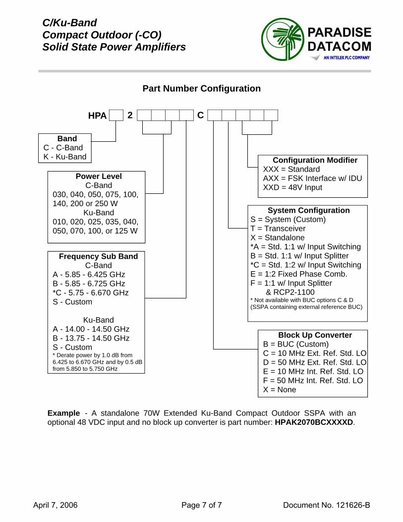
C/Ku-BandCompact Outdoor (-CO)Solid State Power Amplifiers
Part Number Configuration
2 C HPA
Band C - C-Band K - Ku-Band
Power Level C-Band
030, 040, 050, 075, 100, 140, 200 or 250 W
Ku-Band 010, 020, 025, 035, 040, 050, 070, 100, or 125 W
Example - A standalone 70W Extended Ku-Band Compact Outdoor SSPA with an optional 48 VDC input and no block up converter is part number: HPAK2070BCXXXXD.
Frequency Sub Band C-Band
A - 5.85 - 6.425 GHz B - 5.85 - 6.725 GHz *C - 5.75 - 6.670 GHz S - Custom
Ku-Band A - 14.00 - 14.50 GHz B - 13.75 - 14.50 GHz S - Custom * Derate power by 1.0 dB from 6.425 to 6.670 GHz and by 0.5 dB from 5.850 to 5.750 GHz
Block Up Converter B = BUC (Custom) C = 10 MHz Ext. Ref. Std. LO D = 50 MHz Ext. Ref. Std. LO E = 10 MHz Int. Ref. Std. LO F = 50 MHz Int. Ref. Std. LO X = None
System Configuration S = System (Custom) T = Transceiver X = Standalone *A = Std. 1:1 w/ Input Switching B = Std. 1:1 w/ Input Splitter *C = Std. 1:2 w/ Input Switching E = 1:2 Fixed Phase Comb. F = 1:1 w/ Input Splitter & RCP2-1100 * Not available with BUC options C & D (SSPA containing external reference BUC)
Configuration Modifier XXX = Standard AXX = FSK Interface w/ IDU XXD = 48V Input
April 7, 2006 Page 7 of 7 Document No. 121626-B


FIND QTY PART NO DESCRIPTION REFERENCE DESIGNATOR
SINGLE LEVEL MFG BILL OF MATERIAL
REV
1 1 122837-1 RADOME FAB ASS'Y, 16FT, WHITEEA X1
2 1 126851-1 RADOME RISER KIT, 110 IN X 15 INEA
3 1 115912-1 BASE FRAME ASS'Y, 168 IN RADOME, W/PEA D2
4 48 117762-1 SILICONE ADHESIVE, WHT RTV 122, 10.1 EA B
5 1 124955 HARDWARE KIT, 16 FT RADOMEEA
6 3 124903-1 STRAIN RELIEF ASS'YEA B1
7 1 117319-11 LOCTITE, 271 THREADLOCKER, 10MLEA C2
COMMON 124954-1
RADOME ASS'Y, 16 FT
AREVDRAWING NUMBERPROD FAMILY
19-Dec-07EFF. DATE SHT 1 OF 1

NOTES: UNLESS OTHERWISE SPECIFIED1. APPLY ADHESIVE PER SEATEL SPEC. 121730.
2. TORQUE THREADED FASTENERS PERSEATEL SPEC. 122305.
3 DASH 1ONLY.
POSITION RISER PANELS AS SHOWN. RISERSEAMS TO BE OFFSET FROM RADOME PANEL SEAMS.
4
ARELEASE TO PRODUCTION, WS REV X16/10/07N/AA
192
194
BASE FRAME
MATCH BASE FRAMEHOLE PATTERN
BASE PLATE &
1/4-20 HARDWARE
SCALE 1 : 12
PART OF ITEM 5
DETAIL A
MATCH DRILL RISERAND BASE PAN TO
MATCH DRILL DOMESEGMENTS TO RISER
3
DASH DESCRIPTION1 WHITE2 WHITE, W/O BASE FRAME
B
A
2 RISER
3
5X
1
BASE FRAME4
BY
6/5/07
D
C
B
AA
B
C
D
12345678
8 7 6 5 4 3 2
DESCRIPTIONDATE
4030 NELSON AVENUE
Tel. 925-798-7979 Fax. 925-798-7986
TelUNLESS OTHERWISE SPECIFIED
CONCORD, CA 94520
PROJECTION
FINISH:
Sea
3rd ANGLE
DIMENSIONS ARE IN INCHES.DRAWN BY:
APPROVED BY: TITLE:
FIRST USED:
SIZE SCALE:
SHEET NUMBER
DRAWING NUMBER REV
B
LAE
N/A 1:96 124954 A14600-50
N/A
INTERPRET TOLERANCING PER ASME Y14.5M - 1994
1 OF 1
MATERIAL:
1
DRAWN DATE:
ECO#REV
APPROVED DATE:
REVISION HISTORY
RADOME ASS'Y
X.X = .050X.XX = .020
X.XXX = .005ANGLES: .5
W/ RISER, 16 FT
SCALE 1 : 3DETAIL B
1/4-20 HARDWAREPART OF ITEM 5

FIND QTY PART NO DESCRIPTION REFERENCE DESIGNATOR
SINGLE LEVEL MFG BILL OF MATERIAL
REV
1 1 111811-2 BASE FRAME WELDMENT, STEELEA L
2 2 111812-1 PLATE, SPLICE, STEELEA B
3 8 111814-1 BASE FRAME FOOT, 6-INCH, STEELEA C
7 1 111787-2 RADOME BASE PAN FAB, 168 INCH, W/DOEA H
9 1 120191-2 RADOME PAN ACCESS ASS'Y, WHITEEA C2
10 1 124822-3 HARDWARE KIT, BASE FRAME ASS'Y, 110 EA A
COMMON 115912-1
BASE FRAME ASS'Y, 168 IN RADOME, W/PAN ACCESS, STEEL
D2REVDRAWING NUMBERPROD FAMILY
19-Dec-07EFF. DATE SHT 1 OF 1

D1 N/A 01-31-06ADDED -3 NOTE TO DASH TABLE
K.D.H.
D 4995 12-5-05LAST REV. WAS REV. C; REDRAWN IN SWX; DEL MACH. INFO., MNTG HOLE PATTERN, &SHT. 2; DEL ITEMS 5, 6, 8 &STAND WASHERS; ADDED ITEM 10 JP
D2 N/A 7/10/07 MODIFED DASH NUMBER BLOCK, REMOVED STL, 6 IN FT FROM ALL DESCRIPTIONS LAE
168 IN. RADOME
D
C
B
AA
B
C
D
12345678
8 7 6 5 4 3 2 1
BYDESCRIPTION
Tel. 925-798-7979 Fax. 925-798-7986
TelSeaCONCORD, CA 94520
PROJECTION
FINISH:
MATERIAL:
3rd ANGLE
DIMENSIONS ARE IN INCHES.DRAWN BY:
APPROVED BY: TITLE:
FIRST USED:
SIZE SCALE:
SHEET NUMBER
DRAWING NUMBER REV
B
MAB
6/27/2000
1:16 115912 D21 OF 1
DRAWN DATE:
APPROVED DATE:
UNLESS OTHERWISE SPECIFIED
4030 NELSON AVENUE
DATEECO#
BASE FRAME ASS'Y,
REV
REVISION HISTORY
X.X = .050X.XX = .020
X.XXX = .005ANGLES: .5
INTERPRET TOLERANCING PER ASME Y14.5M - 1994
52
8X
9
50 2X
12X50
2X
4X
CAULK
8X
2X
1
5216X 5150
51 51 52
5251
7
51
5150
2
51
5655 5756
54
3
51
DASH DESCRIPTION-1 W/ PAN ACCESS-2 W/O PAN ACCESS-3 W/O BASE PAN
HARDWARE KIT, ITEM 10, LIST OF MATERIALSITEM QTY DESCRIPTION
50 32 SCREW, HEX HD, 1/2-13 X 1-1/2, S.S.51 72 WASHER, FLAT, 1/2, S.S.52 36 NUT, HEX, 1/2-13, S.S.53 4 SCREW, HEX HD, 1/2-13 X 1-3/4, S.S.
FOR GA INSTALL (NOT SHOWN)54 8 WASHER, STAND, OFFSET55 4 SCREW, HEX HD, 1/4-20 X 1-1/4, S.S.56 8 WASHER, FLAT, 1/4, S.S.57 4 NUT, HEX, 1/4-20, S.S.

INSTALLATION ARRANGEMENT
123381 A1

INSTALLATION ARRANGEMENT
123381 A1

FIND QTY PART NO DESCRIPTION REFERENCE DESIGNATOR
SINGLE LEVEL MFG BILL OF MATERIAL
REV
1 3 123494-X (REF ONLY) AIR CONDITIONER, R417AEA
2 3 115708-1 CIRCUIT BREAKER BOX ASS'Y, 220VEA L
3 600 115554-3 CORD, AC POWER, SHIELDED - BELDEN #IN B1
4 50 124830-06 DUCTING, T-7 NW, 6 INFT X1
5 18 111398-1 TERMINAL, SPADE, RED (22-16), #6EA A1
COMMON 124782-1
AIR CONDITIONER KIT, 14600
REVDRAWING NUMBERPROD FAMILY19-Dec-07EFF. DATE SHT 1 OF 1

Dash
Rated Cooling Capacity
(BTU)Voltage
(VAC)Rated
CurrentFrequency
(Hz) RefrigerantSystem
Controller ManufacturerManufacturers Part Number Manufacturers Description
-1 16,000 110 20A 60 R417A Digital Dometic 202000307 HSA16KC/2 417A RADOME 115V-2 16,000 220 12A 50/60 R417A Digital Dometic 202000304 HSA16KCZ/2 417A RADOME 230/1-3 16,000 230 12A 60 R417A Digital Dometic TBD TBD-4 16,000 230 12A 50 R417A Digital Dometic 202000354 HSA16KCZ50 417A 220V/50/1
3.4
INLET
18 MAX
AIR FLOWOUT
CONTROL PANEL
.56
17.85
2.53
12.80
31.8833.00
4X .28
D
C
B
AA
B
C
D
12345678
8 7 6 5 4 3 2 1
4030 NELSON AVENUECONCORD, CA 94520
Tel. 925-798-7979 Fax. 925-798-7986
TelSea
3rd ANGLEPROJECTION
FINISH:
MATERIAL:
UNLESS OTHERWISE SPECIFIEDDIMENSIONS ARE IN INCHES.
DRAWN BY:
APPROVED BY: TITLE:
FIRST USED:
SIZE SCALE:
SHEET NUMBER
DRAWING NUMBER REV
B
RJW
1/8/2007
1:8 123496 C1
N/A
N/A
1 OF 1
DRAWN DATE:X.X = .050X.XX = .020
X.XXX = .005ANGLES: .5
APPROVED DATE:
AIR CONDITIONER,
REVISION HISTORYREV ECO# DATE DESCRIPTION BY
INTERNALINTERPRET TOLERANCING PER ASME Y14.5M - 1994
C1 N/A 1-9-07 CREATED CAD OUTLINE DRAWING RJW
A 4609 10-05-04 RELEASED TO PRODUCTION AMN
C N/A 3-2-06 CHANGED TO TABLE FORMAT V.S.
B 4858 5-5-05 ADD REFERENCE 121113 LR
IN
VIEW A-A
BOTTOM VIEW
15.9
2.23.9
5.46.9
1.0
OUTLET
CLOSED CELL FOAM
1/2" NPT DRAIN
A A
1.50
MAX.15.25
30.00
1.25
.80
2X
.80
Dash
Rated Cooling Capacity
(BTU)Voltage
(VAC)Rated
CurrentFrequency
(Hz) RefrigerantSystem
Controller ManufacturerManufacturers Part Number Manufacturers Description
-1 16,000 110 20A 60 R417A Digital Dometic 202000307 HSA16KC/2 417A RADOME 115V-2 16,000 220 12A 50/60 R417A Digital Dometic 202000304 HSA16KCZ/2 417A RADOME 230/1-3 16,000 230 12A 60 R417A Digital Dometic TBD TBD-4 16,000 230 12A 50 R417A Digital Dometic 202000354 HSA16KCZ50 417A 220V/50/1

FIND QTY PART NO DESCRIPTION REFERENCE DESIGNATOR
SINGLE LEVEL MFG BILL OF MATERIAL
REV
1 1 125160-3 PCU ENCLOSURE ASS'Y, TONE SWITCHINEA C
2 1 116034 HOME SWITCH ASS'Y, SHIELDEDEA F
3 1 116000-2 SERVO AMPLIFIER ASS'YEA J1
4 1 116024-3 SHIELDED POLANG RELAY ASS'YEA J2
5 1 122208-1 LEVEL CAGE ASS'Y, 90 DEG EL RANGE, INEA H
6 1 116047-1 MOTOR, SIZE 34, BLDC, 15 PIN (CL, EL, AZ)EA H1
7 1 116311 SPROCKET, 12T (AZ ONLY)EA B
8 1 116325 PULLEY, 1/5P 15T (AZ ONLY)EA D
9 1 114590-143 SCREW, SOCKET SET-CUP, 6-32 x 3/16, S. (AZ ONLY)EA
10 2 116577 PULLEY, 1/5P 15T (CL, EL)EA A
11 3 115352-472 DOWEL PIN, 1/8 x 5/8 IN, S.S. (CL, EL, AZ)EA
12 1 117319-10 LOCTITE, 271 THREADLOCKER, 0.5MLEA C2
13 1 122977-3 BELT KIT, 14600 PEDESTAL, DISHSCANEA A
14 1 121966-2 GPS ANTENNA, RETERMINATED, 21.0 LEA D
COMMON 123428-3
SPARE PARTS KIT, 14600 DISHSCAN, STANDARD
BREVDRAWING NUMBERPROD FAMILY
07-Dec-07EFF. DATE SHT 1 OF 1

FIND QTY PART NO DESCRIPTION REFERENCE DESIGNATOR
SINGLE LEVEL MFG BILL OF MATERIAL
REV
1 1 122532-1 SHIELDED LEVEL CAGE MOTOR ASS'Y, .0EA D1
2 1 116053 ENCODER ASS'YEA D
3 1 114106-12 PULLEY, 1/5P 25T, 2FLG (ENCODER)EA 0
4 2 114590-190 SCREW, SOCKET SET-CUP, 8-32 x 1/4, S.S. (ENCODER)EA
5 1 116782-1 MODEM ASS'Y, PEDESTAL, 4-CH. RFEA J
6 1 116782-2 MODEM ASS'Y, BASE, 4-CH. RFEA J
7 1 117611-3 MODEM ASS'Y, PEDESTAL, 3 CH. -200, 50 EA G
8 1 117611-4 MODEM ASS'Y, BASE, 3 CH. -200, 50 OHMEA G
9 3 114789-810 TRANSPORT CONTAINEREA
COMMON 123429-2
SPARE PARTS KIT, 14600-50 DISHSCAN, PREMIUM
AREVDRAWING NUMBERPROD FAMILY
07-Dec-07EFF. DATE SHT 1 OF 1

FIND QTY PART NO DESCRIPTION REFERENCE DESIGNATOR
SINGLE LEVEL MFG BILL OF MATERIAL
REV
1 1 119876 GPS, GARMINEA A
2 1 116466 ROTARY JOINT, 4.5 GHz, DUAL COAX.EA C1
3 1 121009-2 POWER SUPPLY ASS'Y, HEAVY DUTYEA D
4 1 123842-1 POWER SUPPLY ASS'Y, IDEC, PS5R-SE, 4EA A
5 1 124744-1 RELAY ASS'Y, TX WAVEGUIDEEA A3
6 1 124741-1 SWITCH ASS'Y, COAX, 50 OHMEA A
7 1 114320-5 BLOCK DOWNCONVERTER, C-BAND, DC BEA C1
8 1 121250-2 POWER RING ASS'Y (96 IN. CONTACT WIREA C3
9 1 124744-2 RELAY ASS'Y, RX WAVEGUIDEEA A3
10 1 116596-2 BIAS-T, DC BLOCK, 2.5-6GHZEA C
COMMON 123430-3
SPARE PARTS KIT, 14600-50 DISHSCAN, TXRX, MASTER
BREVDRAWING NUMBERPROD FAMILY
07-Dec-07EFF. DATE SHT 1 OF 1
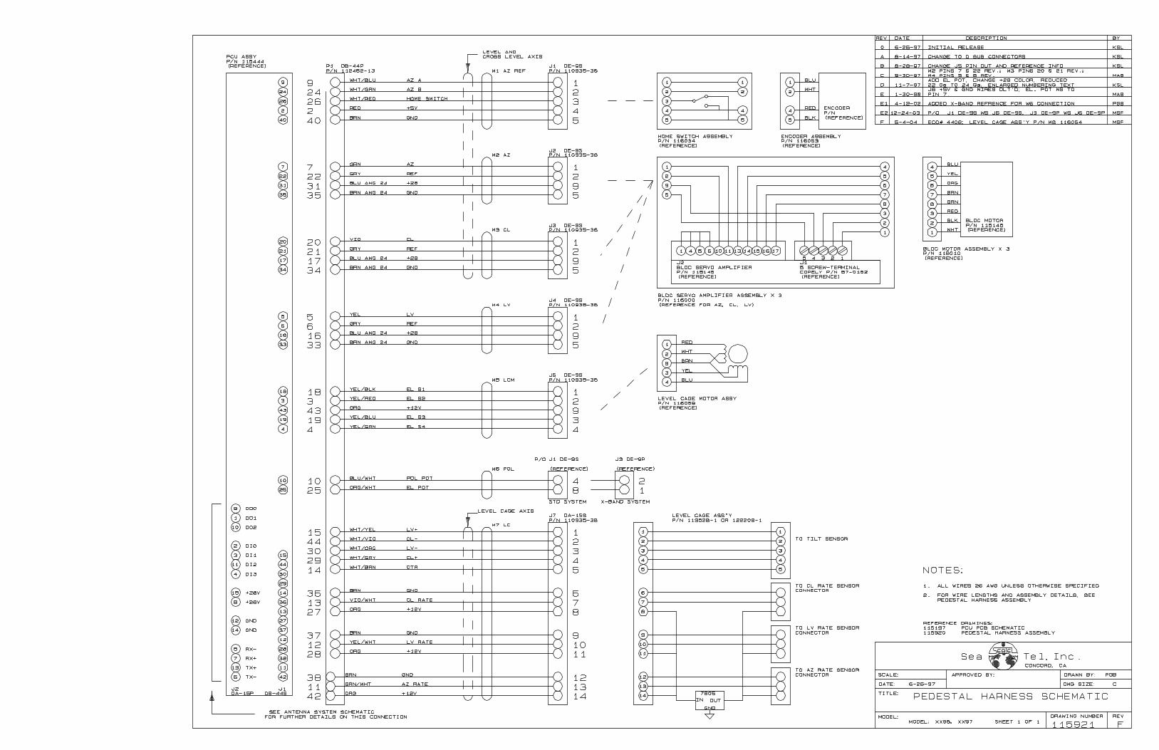

FIND QTY PART NO DESCRIPTION REFERENCE DESIGNATOR
SINGLE LEVEL MFG BILL OF MATERIAL
REV
1 1 112657 MACHINING, TERMINAL MOUNTING STRIPEA D
2 1 116529 PCB ASS'Y, TERMINAL MOUNTING, 25 PINEA C
3 1 112936 CABLE ASS'Y, D-SUB, 25 PINEA D
4 1 116527 PCB ASS'Y, TERMINAL MOUNTING, 9 PINEA A
5 1 116669-36 CABLE ASS'Y, D-SUB, 9-PIN, 36 IN.EA B
7 4 121228-3072 STANDOFF, HEX, F/F, 6-32 X .25 OD X .50, EA
9 4 114588-146 SCREW, PAN HD, PHIL, 6-32 x 3/8, S.S.EA
10 4 114588-144 SCREW, PAN HD, PHIL, 6-32 x 1/4, S.S.EA
11 8 114588-107 SCREW, PAN HD, PHIL, 4-40 x 5/16, S.S.EA
ELEC 116676
TERMINAL MOUNTING STRIP ASS'Y, ACU
A3REVDRAWING NUMBERPROD FAMILY
19-Mar-07EFF. DATE SHT 1 OF 1

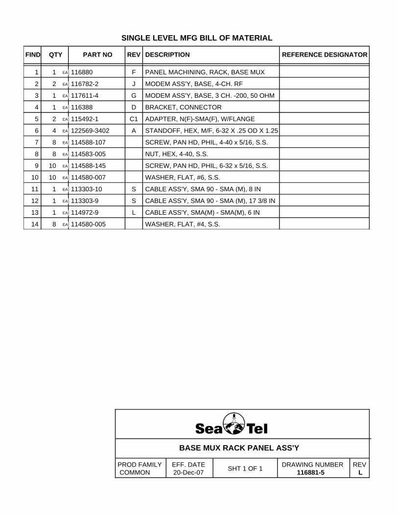
FIND QTY PART NO DESCRIPTION REFERENCE DESIGNATOR
SINGLE LEVEL MFG BILL OF MATERIAL
REV
1 1 116880 PANEL MACHINING, RACK, BASE MUXEA F
2 2 116782-2 MODEM ASS'Y, BASE, 4-CH. RFEA J
3 1 117611-4 MODEM ASS'Y, BASE, 3 CH. -200, 50 OHMEA G
4 1 116388 BRACKET, CONNECTOREA D
5 2 115492-1 ADAPTER, N(F)-SMA(F), W/FLANGEEA C1
6 4 122569-3402 STANDOFF, HEX, M/F, 6-32 X .25 OD X 1.25EA A
7 8 114588-107 SCREW, PAN HD, PHIL, 4-40 x 5/16, S.S.EA
8 8 114583-005 NUT, HEX, 4-40, S.S.EA
9 10 114588-145 SCREW, PAN HD, PHIL, 6-32 x 5/16, S.S.EA
10 10 114580-007 WASHER, FLAT, #6, S.S.EA
11 1 113303-10 CABLE ASS'Y, SMA 90 - SMA (M), 8 INEA S
12 1 113303-9 CABLE ASS'Y, SMA 90 - SMA (M), 17 3/8 INEA S
13 1 114972-9 CABLE ASS'Y, SMA(M) - SMA(M), 6 INEA L
14 8 114580-005 WASHER, FLAT, #4, S.S.EA
COMMON 116881-5
BASE MUX RACK PANEL ASS'Y
LREVDRAWING NUMBERPROD FAMILY
20-Dec-07EFF. DATE SHT 1 OF 1
