installation and operators manual - pigtek® fill system supplying two hi-speed multiflo®...
TRANSCRIPT

Ja
MULTIFLO®
Installation and Operators Manual
MA580Nnuary 2007

Chore-Time Warranty MULTIFLO®
Chore-Time Poultry Production Systems, a division of CTB, Inc., (“Chore-Time”), warrants each new CHORE-TIME® product manufactured by it to be free from defects in material or workmanship for one-year from and after the date of initial installation by or for the original purchaser. If such a defect is found by Chore-Time to exist within the one-year period, Chore-Time will, at its option, (a) repair or replace such product free of charge, F.O.B. the factory of manufacture, or (b) refund to the original purchaser the original purchase price, in lieu of such repair or replacement. Labor costs associated with the replacement or repair of the product are not covered by the Manufacturer.
Additional extended warranties for the equipment and/or systems listed below are provided to the original purchaser as follows (for all other CHORE-TIME® products purchased, the one-year warranty period shall apply):
1. TURBO® and RLX™ fans, less motors - 3 years
2. TURBO® fan fiberglass housings, polyethylene cones, and cast aluminum blades - for the life of the product
3. TURBO® fan motors and bearings - 2 years
4. TURBO® fan components (including plastic shutters) - 3 years
5. Poultry feeder pans that become unusable within five years from the date of installation - Warranty prorated after three years usage
6. Rotating centerless augers, excluding applications involving high moisture feed stuffs (exceeding 18%), for ten years from the date of installation. Note: MULTIFLO® and applications involving high moisture feed stuffs are subject to a one-year warranty
7. Chore-Time manufactured roll-formed steel auger tubes for ten years from the date of installation
8. ULTRAFLO® Breeder Feeding System auger and feed trough are warranted for a period of five years from the date of original installation against repeated breakage of the auger or wear-through of the feed trough caused solely by the auger
9. ULTRAPAN® Feeding System augers are warranted for a period of five years from the date of installation
Chore-Time Warranty
2
MA580N
MULTIFLO® Chore-Time Warranty
CONDITIONS AND LIMITATIONS1. The product must be installed by and operated in accordance with the instructions published by the
Manufacturer or Warranty will be void.
2. Warranty is void if all components of the system are not original equipment supplied by the Manufacturer.
3. This product must be purchased from and installed by an authorized distributor or certified representative thereof or the Warranty will be void.
4. Malfunctions or failure resulting from misuse, abuse, negligence, alteration, accident, or lack of proper maintenance shall not be considered defects under the Warranty.
5. This Warranty applies only to systems for the care of poultry and livestock. Other applications in industry or commerce are not covered by this Warranty.
Chore-Time shall not be liable for any consequential or special damage which any purchaser may suffer or claim to suffer as a result of any defect in the product. “Consequential” or special damages” as used herein include, but are not limited to, lost or damaged products or goods, costs of transportation, lost sales, lost orders, lost income, increased overhead, labor and incidental costs and operational inefficiencies.
THIS WARRANTY CONSTITUTES THE MANUFACTURER’S ENTIRE AND SOLE WARRANTY AND THIS MANUFACTURER DISCLAIMS ANY AND ALL OTHER WARRANTIES, INCLUDING, BUT NOT LIMITED TO, EXPRESS AND IMPLIED WARRANTIES AS TO MERCHANTABILITY, FITNESS FOR PARTICULAR PURPOSES SOLD AND DESCRIPTION OR QUALITY OF THE PRODUCT FURNISHED HEREUNDER.
Chore-Time Distributors are not authorized to modify or extend the terms and conditions of this Warranty in any manner or to offer or grant any other warranties for Chore-Time products in addition to those terms expressly stated above.
An officer of CTB, Inc. must authorize any exceptions to this Warranty in writing. Chore-Time reserves the right to change models and specifications at any time without notice or obligation to improve previous models.
Effective: July 2004
Chore-Time Poultry Production SystemsA division of CTB, Inc.
410 N. Higbee Street • Milford, Indiana 46542 • U.S.A.Phone (574) 658-4101 • Fax (877) 730-8825
E-mail: [email protected] • Internet: www.ctbinc.comThank YouThe employees of Chore-Time would like to thank your for your recent Chore-Time purchase. If a problem should arise, your Chore-Time distributor can supply the necessary information to help you.
*Chore-Time Poultry Feeder Pan Pro Rata Schedule
Year from date of installation during which pan becomes unusable
Charge to be paid by the purchaser for replacement.
0 - 1 years NO CHARGE1 - 2 years NO CHARGE2 - 3 years NO CHARGE3 - 4 years 4/10 of then current list price4 - 5 years 5/10 of then current list price
M
A580N 3
Contents
Topic Page
4
Chore-Time Warranty . . . . . . . . . . . . . . . . . . . . . . . . . . . . . . . . . . . . . . . . . . . . . . . . . . . . . . . . . . . . 2CONDITIONS AND LIMITATIONS . . . . . . . . . . . . . . . . . . . . . . . . . . . . . . . . . . . . . . . . . . . . . . . . . . . . . 3
About This Manual. . . . . . . . . . . . . . . . . . . . . . . . . . . . . . . . . . . . . . . . . . . . . . . . . . . . . . . . . . . . . . . 6
Safety Information . . . . . . . . . . . . . . . . . . . . . . . . . . . . . . . . . . . . . . . . . . . . . . . . . . . . . . . . . . . . . . . 6
Safety Instructions . . . . . . . . . . . . . . . . . . . . . . . . . . . . . . . . . . . . . . . . . . . . . . . . . . . . . . . . . . . . . . . 7Follow Safety Instructions . . . . . . . . . . . . . . . . . . . . . . . . . . . . . . . . . . . . . . . . . . . . . . . . . . . . . . . . . . . . . . 7Decal Descriptions . . . . . . . . . . . . . . . . . . . . . . . . . . . . . . . . . . . . . . . . . . . . . . . . . . . . . . . . . . . . . . . . . . . . 7
DANGER: Moving Auger. . . . . . . . . . . . . . . . . . . . . . . . . . . . . . . . . . . . . . . . . . . . . . . . . . . . . . . . . . . 7DANGER: Electrical Hazard . . . . . . . . . . . . . . . . . . . . . . . . . . . . . . . . . . . . . . . . . . . . . . . . . . . . . . . . 7CAUTION: . . . . . . . . . . . . . . . . . . . . . . . . . . . . . . . . . . . . . . . . . . . . . . . . . . . . . . . . . . . . . . . . . . . . . . 7
General. . . . . . . . . . . . . . . . . . . . . . . . . . . . . . . . . . . . . . . . . . . . . . . . . . . . . . . . . . . . . . . . . . . . . . . . . 7Support Information . . . . . . . . . . . . . . . . . . . . . . . . . . . . . . . . . . . . . . . . . . . . . . . . . . . . . . . . . . . . . . . . . . . 7
MULTIFLO® SPECIFICATIONS. . . . . . . . . . . . . . . . . . . . . . . . . . . . . . . . . . . . . . . . . . . . . . . . . . 8Auger Information . . . . . . . . . . . . . . . . . . . . . . . . . . . . . . . . . . . . . . . . . . . . . . . . . . . . . . . . . . . . . . . . . . . . 8
Auger Specifications . . . . . . . . . . . . . . . . . . . . . . . . . . . . . . . . . . . . . . . . . . . . . . . . . . . . . . . . . . . . . . . 8MULTIFLO® Effective Length Calculation . . . . . . . . . . . . . . . . . . . . . . . . . . . . . . . . . . . . . . . . . . . . . . . . 9
Example with 90° Elbow: . . . . . . . . . . . . . . . . . . . . . . . . . . . . . . . . . . . . . . . . . . . . . . . . . . . . . . . . . . . 9Example with 180° Elbow: . . . . . . . . . . . . . . . . . . . . . . . . . . . . . . . . . . . . . . . . . . . . . . . . . . . . . . . . . . 9
MULTIFLO® Components . . . . . . . . . . . . . . . . . . . . . . . . . . . . . . . . . . . . . . . . . . . . . . . . . . . . . . . 10Tubes, Elbows. . . . . . . . . . . . . . . . . . . . . . . . . . . . . . . . . . . . . . . . . . . . . . . . . . . . . . . . . . . . . . . . . . . . . . . .10Welding Bridge. . . . . . . . . . . . . . . . . . . . . . . . . . . . . . . . . . . . . . . . . . . . . . . . . . . . . . . . . . . . . . . . . . . . . . .10Service Section . . . . . . . . . . . . . . . . . . . . . . . . . . . . . . . . . . . . . . . . . . . . . . . . . . . . . . . . . . . . . . . . . . . . . . .10Side Draw Boots . . . . . . . . . . . . . . . . . . . . . . . . . . . . . . . . . . . . . . . . . . . . . . . . . . . . . . . . . . . . . . . . . . . . . .10Driver Assembly/Power Unit . . . . . . . . . . . . . . . . . . . . . . . . . . . . . . . . . . . . . . . . . . . . . . . . . . . . . . . . . . . .11Sleeve Switch Control . . . . . . . . . . . . . . . . . . . . . . . . . . . . . . . . . . . . . . . . . . . . . . . . . . . . . . . . . . . . . . . . .11Auger . . . . . . . . . . . . . . . . . . . . . . . . . . . . . . . . . . . . . . . . . . . . . . . . . . . . . . . . . . . . . . . . . . . . . . . . . . . . . .11
Planning the MULTIFLO® System . . . . . . . . . . . . . . . . . . . . . . . . . . . . . . . . . . . . . . . . . . . . . . . . 12MULTIFLO® Boot Placement. . . . . . . . . . . . . . . . . . . . . . . . . . . . . . . . . . . . . . . . . . . . . . . . . . . . . . . . . . .12Determine Where to Install Power Units . . . . . . . . . . . . . . . . . . . . . . . . . . . . . . . . . . . . . . . . . . . . . . . . . . .12Outlet Drop Size and Placement . . . . . . . . . . . . . . . . . . . . . . . . . . . . . . . . . . . . . . . . . . . . . . . . . . . . . . . . . .12Examples of MULTIFLO® System Layout . . . . . . . . . . . . . . . . . . . . . . . . . . . . . . . . . . . . . . . . . . . . . . . . .13
MULTIFLO® Installation . . . . . . . . . . . . . . . . . . . . . . . . . . . . . . . . . . . . . . . . . . . . . . . . . . . . . . . . 15Adapter Plate and MULTIFLO® Boot. . . . . . . . . . . . . . . . . . . . . . . . . . . . . . . . . . . . . . . . . . . . . . . . . . . . .15Auger Tubes and Nylon Elbows. . . . . . . . . . . . . . . . . . . . . . . . . . . . . . . . . . . . . . . . . . . . . . . . . . . . . . . . . .16Cementing the Auger Tubes . . . . . . . . . . . . . . . . . . . . . . . . . . . . . . . . . . . . . . . . . . . . . . . . . . . . . . . . . . . . .16Power Unit and Driver Assembly Installation . . . . . . . . . . . . . . . . . . . . . . . . . . . . . . . . . . . . . . . . . . . . . . .17Install the Welding Bridge . . . . . . . . . . . . . . . . . . . . . . . . . . . . . . . . . . . . . . . . . . . . . . . . . . . . . . . . . . . . . .17Install Hand Crank Assembly . . . . . . . . . . . . . . . . . . . . . . . . . . . . . . . . . . . . . . . . . . . . . . . . . . . . . . . . . . . .18Installing the Auger . . . . . . . . . . . . . . . . . . . . . . . . . . . . . . . . . . . . . . . . . . . . . . . . . . . . . . . . . . . . . . . . . . .19Auger Connector Installation . . . . . . . . . . . . . . . . . . . . . . . . . . . . . . . . . . . . . . . . . . . . . . . . . . . . . . . . . . . .20Brazing the Auger . . . . . . . . . . . . . . . . . . . . . . . . . . . . . . . . . . . . . . . . . . . . . . . . . . . . . . . . . . . . . . . . . . . . .22Install the Service Section Cover . . . . . . . . . . . . . . . . . . . . . . . . . . . . . . . . . . . . . . . . . . . . . . . . . . . . . . . . .22Install the Hand Crank Closure. . . . . . . . . . . . . . . . . . . . . . . . . . . . . . . . . . . . . . . . . . . . . . . . . . . . . . . . . . .23Install the Boot Clean-Out Cover . . . . . . . . . . . . . . . . . . . . . . . . . . . . . . . . . . . . . . . . . . . . . . . . . . . . . . . . .23Install the Gear Drive and Hub . . . . . . . . . . . . . . . . . . . . . . . . . . . . . . . . . . . . . . . . . . . . . . . . . . . . . . . . . . .24
Wiring the System. . . . . . . . . . . . . . . . . . . . . . . . . . . . . . . . . . . . . . . . . . . . . . . . . . . . . . . . . . . . . . . 25Notes for Wiring Diagrams. . . . . . . . . . . . . . . . . . . . . . . . . . . . . . . . . . . . . . . . . . . . . . . . . . . . . . . . . . . . . .25MULTIFLO Motor Wiring (Motor Part No. 14750) GE 1/2 hp . . . . . . . . . . . . . . . . . . . . . . . . . . . . . . . . .25
MA580N

Contents - continued
Topic Page
Hi-Speed MULTIFLO Motor Wiring (Motor Part No. 5051) GE 3/4 hp . . . . . . . . . . . . . . . . . . . . . . . . . .25FLEX-AUGER® Fill System Supplying a single MULTIFLO® loop . . . . . . . . . . . . . . . . . . . . . . . . . . . .26FLEX-AUGER® Fill System Supplying a single Hi-Speed MULTIFLO® loop . . . . . . . . . . . . . . . . . . . .27FLEX-AUGER® Fill System Supplying two MULTIFLO® loops w/boot switch . . . . . . . . . . . . . . . . . . .28FLEX-AUGER® Fill System Supplying two Hi-Speed MULTIFLO® loops w/boot switch . . . . . . . . . . .29FLEX-AUGER® Fill System Supplying three MULTIFLO® loops w/boot switch . . . . . . . . . . . . . . . . . .30Parts Listing . . . . . . . . . . . . . . . . . . . . . . . . . . . . . . . . . . . . . . . . . . . . . . . . . . . . . . . . . . . . . . . . . . . 31Power Unit and Driver Assembly . . . . . . . . . . . . . . . . . . . . . . . . . . . . . . . . . . . . . . . . . . . . . . . . . . . . . . . . .31
Complete Power Unit and Driver Assemblies. . . . . . . . . . . . . . . . . . . . . . . . . . . . . . . . . . . . . . . . . . . .31Control And Intermediate Boot Assemblies . . . . . . . . . . . . . . . . . . . . . . . . . . . . . . . . . . . . . . . . . . . . . . . . .32Proximity Sleeve Switch Part No. 40508 . . . . . . . . . . . . . . . . . . . . . . . . . . . . . . . . . . . . . . . . . . . . . . . . . . .33Installation Tools . . . . . . . . . . . . . . . . . . . . . . . . . . . . . . . . . . . . . . . . . . . . . . . . . . . . . . . . . . . . . . . . . . . . .34Service Section Part No. 8710 . . . . . . . . . . . . . . . . . . . . . . . . . . . . . . . . . . . . . . . . . . . . . . . . . . . . . . . . . . .34Line Components . . . . . . . . . . . . . . . . . . . . . . . . . . . . . . . . . . . . . . . . . . . . . . . . . . . . . . . . . . . . . . . . . . . . .35
Trouble Shooting Guide . . . . . . . . . . . . . . . . . . . . . . . . . . . . . . . . . . . . . . . . . . . . . . . . . . . . . . . . . . 36
MA580N 5
About This Manual MULTIFLO®
The intent of this manual is to help you in two ways. One is to follow step-by-step in the order of assembly of your product. The other way is for easy reference if you have questions in a particular area.
Important: Read ALL instructions carefully before starting construction. Important: Pay particular attention to all SAFETY information.• Metric measurements are shown in millimeters and in brackets, unless otherwise specified. “ " ” equals inches
and “ ' ” equals feet in English measurements.Examples: 1" [25.4]4' [1 219]
• Optional equipment contains necessary instructions for assembly or operation.
• Very small numbers near an illustration (i.e., 1257-48) are identification of the graphic, not a part number.
Note: The original, authoritative version of this manual is the English version produced by CTB, Inc. or any of its subsidiaries or divisions, (hereafter collectively referred to as "CTB"). Subsequent changes to any manual made by any third party have not been reviewed nor authenticated by CTB. Such changes may include, but are not limited to, translation into languages other than English, and additions to or deletions from the original content. CTB disclaims responsibility for any and all damages, injuries, warranty claims and/or any other claims associated with such changes, inasmuch as such changes result in content that is different from the authoritative CTB-published English version of the manual. For current product installation and operation information, please contact the customer service and/or technical service departments of the appropriate CTB subsidiary or division. Should you observe any questionable content in any manual, please notify CTB immediately in writing to: CTB Legal Department, P.O. Box 2000, Milford, IN 46542-2000 USA.
Caution, Warning and Danger Decals have been placed on the equipment to warn of potentially dangerous situations. Care should be taken to keep this information intact and easy to read at all times. Replace missing or damaged safety decals immediately.Using the equipment for purposes other than specified in this manual may cause personal injury and/or damage to the equipment.
Safety–Alert SymbolThis is a safety–alert symbol. When you see this symbol on your equipment, be alert to the potential for personal injury. This equipment is designed to be installed and operated as safely as possible...however, hazards do exist.
Understanding Signal WordsSignal words are used in conjunction with the safety–alert symbol to identify the severity of the warning.
DANGER indicates an imminently hazardous situation which, if not avoided, WILL result in death or serious injury.WARNING indicates a potentially hazardous situation which, if not avoided, COULD result in death or serious injury.CAUTION indicates a hazardous situation which, if not avoided, MAY result in minor or moderate injury.
About This Manual
Safety Information
6
MA580N
MULTIFLO® Safety Instructions
Follow Safety InstructionsCarefully read all safety messages in this manual and on your equipment safety signs. Follow recommended precautions and safe operating practices.Keep safety signs in good condition. Replace missing or damaged safety signs.
Decal DescriptionsDANGER: Moving AugerThis decal is placed on the Panel Weldment.
Severe personal injury will result, if the electrical power is not disconnected, prior to servicing the equipment.
DANGER: Electrical HazardDisconnect electrical power before inspecting or servicing equipment
unless maintenance instructions specifically state otherwise.
Ground all electrical equipment for safety.
All electrical wiring must be done by a qualified electrician in accordance with local and national electric codes.
Ground all non-current carrying metal parts to guard against electrical shock.
With the exception of motor overload protection, electrical disconnects and over current protection are not supplied with the equipment.
CAUTION:Use caution when working with the Auger—springing Auger may cause
personal injury.
Support InformationUsing this equipment for any other purpose or in a way not within the operating recommendations specified in this manual will void the warranty and may cause personal injury.This manual is designed to provide comprehensive planning and installation information. The Table of Contents provides a convenient overview of the information in this manual.
Safety Instructions
GeneralManboot 3/98
M
A580N 7
MULTIFLO® SPECIFICATIONS MULTIFLO®
The MULTIFLO® Feed Delivery System is a closed “loop” system which pulls the auger through the tube. The system is used primarily in nurseries, gestation, and dairy houses. It is recommended for systems with running times of less than 2 hours per day and no high moisture corn.
Read all instructions carefully and familiarize yourself with the components before beginning to install the MULTIFLO® system. Determine approximate layout of the system where each component will be placed, how much space it will require, how it will be suspended, and so forth. be careful to plan the system so it does not interfere with ventilation, watering systems, or other equipment in the building. “Examples of MULTIFLO® System Layout” on page 13 shows some possible MULTIFLO® “layouts”. These are to be used as examples only.
Auger Information7961MF Auger is specifically designed for use in MULTIFLO® Systems. It differs from standard 7961 Auger
used with Model 55 Feeding Systems, the 7961MF Auger contains no factory brazes. MULTIFLO® Auger should be connected using an Auger Connector when it is necessary to join sections of the 7961MF Auger. However, the welding or brazing technique is acceptable. Remember, brazing MULTIFLO® auger is considerable different than for other Chore-Time auger systems (see page 9).
Auger SpecificationsAuger Tube: 55 mm PVC TubeElbows: 90 degree, 2" (51 mm) I.D. two piece nylon elbow w/24" (610 mm) center line radius. The
maximum number of 90 degree elbows allowed for each MULTIFLO® loop is 4.180 degree, 2.12" (54 mm) O.D. x 2" I.D. Hardened Steel Elbow w/39" (990 mm) center to center turn. The maximum number of 180 degree elbows allowed for each MULTIFLO® loop is 2.
Auger: 7961MF for systems 400’ (122 m) of shorter, auger should be one piece. Maximum length auger for shipment is 400’ (122 m). It is important to specify length of the system when ordering auger. Auger for longer systems will be sent in most desirable section lengths. Example: for a 450’ (137 m) MULTIFLO® System, it would be better to use two 225’ (69 m) sections of auger than one 400’ (122 m) section and one 50’ (15 m) section. Specify system length and Chore-Time will supply the best available combination of auger. Handle auger carefully. Store flat if it is to be stored for a period of time prior to installation.
Auger Drive: Helical Gear.Power Unit: Standard 1/2 HP, 62 RPM Direct Drive, 230 V, 60 Hz; 220 V, 50 Hz, Single Phase; 380 V, 50
Hz, 3 PhaseHi-Speed 3/4 HP, 95 RPM Direct Drive, 230 V, 60 Hz, Single Phase
Power Unit Capacity: 400’ (122 m) Effective Length. Effective Length is based on feed with 40 lb/cu.ft (64 kg/cu. meter) density.
System Capacity: 1200’ (366 m) Effective Length (with three Power Units-maximum)Delivery Capacity:
Standard: 15 lb/min (6.8 kg/min) with Model 55 FLEX AUGER® Fill SystemStandard: 18 lb/min (8.1 kg/min) with Model 75 or HMC FLEX AUGER® Fill System @ 129 RPMHi-Speed: 50 lb/min (22.6 kg/min) with Model 75 or HMC FLEX AUGER® Fill System @ 348 RPM
Feed Types: Ground feeds, crumbles, and pellets up to/including 3/16" dia. x 1/2" long (4.7 x 12.7 mm), not to exceed 18% moisture. The MULTIFLO® system is not recommended for high moisture feed.
MULTIFLO® SPECIFICATIONS
8
MA580N
MULTIFLO® MULTIFLO® SPECIFICATIONS
MULTIFLO® Effective Length CalculationThe Effective Length if a MULTIFLO System is calculated an shown. Before beginning to install the system,
determine the Effective Length of the system.
Important: You must know the Effective Length before placing the power units, service section area, and other system components.
Effective Length = Total Feet (meters) of Straight LengthsPLUS
Number of 90° Elbows x 30’ (9.1 m)or
Number of 180° Elbows x 60’ 18.2 m)
Example with 90° Elbow:
60’ x 2 = 120’, 20’ x 2 = 40’: given straight line length of 160’4 (90 degree elbows) x 30’ = 120’: given elbow length of 120
Straight line length (160’) + elbow length (120’) = Effective Length (280’)
Example with 180° Elbow:
80’ x 2 = 160’: given straight line length of 160’2 (180 degree elbows) x 60’ = 120’: given elbow length of 120’
Straight line length (160’) + elbow length (120’) = Effective Length (280’)
60’
20’
80’
39"
M
A580N 9
MULTIFLO® Components MULTIFLO®
Tubes, ElbowsPVC Tubes are used to form the main portion of the
delivery system. Tube is supplied in 10’ (3 m) sections with an expanded end designed to fit over the end of the next tube for easy installation. PVC couplers are available for fitting tubes together without an expanded end. Nylon Elbows are 90 degree units with a compact, 24" (610 mm) Center-line radius or 180 degree with 39" (990 mm) center to center turn and have special PVC adapter to cement to tubes and clamp to elbows. Installation combinations for layout of the system are infinite, the layout charts “Examples of MULTIFLO® System Layout” on page 13 give examples of possible MULTIFLO® system designs. These are examples only. Many other component combinations are possible.
Welding BridgeThe Welding Bridge is used to hold the tubes in place when
the Service Section is removed for auger brazing or servicing. It is recommended that the auger Welding Bridge be left in place after installation.
Service SectionTo allow access to the auger, a 17" (432 mm) section of auger
tube should be removed and replace with a clear plastic service access cover. During installation, this 17" (432 mm) opening is used to install the auger, in conjunction with a welding bridge and welding clamp both of which are MULTIFLO® installation tools. After installation is completed, this service section will allow maintenance and repair to the auger. Additionally, the service sections can be used as a visual aid to the system’s operation.
Side Draw BootsThe Side Draw Boots fit beneath the FLEX-AUGER® Control
Unit to receive the feed from the FLEX-AUGER® Feed Delivery System. The Side Draw feature controls the amount of feed entering the system supplying a smooth, steady feed supply to the MULTIFLO® line. The Side Draw Boots are single directional and should be installed according to the direction of auger travel.
For standard speed systems, use the standard Side Draw Boot. For hi-speed systems use the Hi-Speed Side Draw Boot.
MULTIFLO® Components
90° Elbow
180° Elbow
10
MA580N
MULTIFLO® MULTIFLO® Components
Driver Assembly/Power UnitThe MULTIFLO® Power Units are available in three voltages;
230V-60Hz-1PH, 220V-50Hz-1PH, and 220/380V-50Hz-3PH as direct drive power units. They are rated at 1/2 HP, 62 RPM and 3/4 HP, 95 RPM (Hi-Speed). They drive the helical gear driver assembly which powers the auger. Each power unit has a maximum capacity of 400’ (122 m) effective length See “MULTIFLO® Effective Length Calculation” on page 9. with the MULTIFLO® system.
Sleeve Switch ControlThe Sleeve feature of this switch allows the proximity switch to
be located at the source of the feed. It will sense the level of feed passing in the auger. The Sleeve Switch is supplied with an override timer to allow start-up and purging of the MULTIFLO® System.
AugerMULTIFLO® Auger circulates around the system delivering
feed. Unlike other Chore-Time augers it is not turned by the power unit but is driven with a helical gear. Therefore, it has some different capabilities and requirements. It is recommended the auger be connected using an Auger Connector, See the Auger Connector installation section in this manual. An alternate way of connecting the auger is brazing. See the Auger Brazing section in this manual.
MULTIFLO® Auger is shipped in lengths up to 400’ (122 m). Specify length of the system when ordering auger. The MULTIFLO Auger has no brazes as shipped from the factory. Therefore, for systems shorter than 400’ (122 m) the auger can be one-piece with only a connector or braze where the ends are joined following installations. For longer systems it will be necessary to join sections of auger together but these should be kept to a minimum and it is very important to follow the connecting recommendations in this manual!
M
A580N 11
Planning the MULTIFLO® System MULTIFLO®
Planning for the MULTIFLO® installation should be coordinated with planning for the FLEX-AUGER® feed delivery system installation so the advantages of each system can be used effectively. The diagram in Example 4 on page 13 shows how a FLEX-AUGER and MULTIFLO loop can work together to fill three rows of feeders. See the FLEX-AUGER operator’s manual for information regarding the FLEX-AUGER feed delivery system.
Chains, “S” Hooks, and screw hooks are provided to suspend the system at least every 5’ (1.5 m). The elbows should be supported in at least 2 places.
Important: Keep the system as straight and level as possible.
MULTIFLO® Boot PlacementThe MULTIFLO Side Draw Boot placement is determined by were the FLEX-AUGER feed delivery system is
terminated. Installation of the FLEX-AUGER feed delivery system should be planned with this in mind. The MULTIFLO Side Draw Boot is directional.
Important: It is not recommended to place the MULTIFLO Boot directly adjoining an elbow. Try to locate the boot a few feet prior to ar after an elbow in the system.
Determine Where to Install Power UnitsNote placement of the power units See “Examples of MULTIFLO® System Layout” on page 13..
See “MULTIFLO® Effective Length Calculation” on page 9. to determine the Effective Length of the system.
The “Effective Length” between Power Units must not exceed 400’ (122 m) regardless of the number or position of elbows
Power Units should be placed evenly around the system keeping:
• Single Power Units opposite the boot• Boot approximately centered between two power units in multiple power unit systems (See “Examples
of MULTIFLO® System Layout” on page 13. Examples 2-4)• The “Effective Length” per power unit should be kept as equal (even) as possible.
If possible, install the Power Units in a straight section of tube and not adjacent to an elbow. See Example 1 on page 13.
Outlet Drop Size and PlacementA 1-1/2” (38 mm) hole is required at each outlet drop or drop feeder location. The last drop feeder before the
control unit should not be more than 3’ (1 m) from the control unit.
DO NOT install outlet drops on elbows, feed is required to cushion the auger here. The maximum angle of the outlet drop is 30 degrees.
Planning the MULTIFLO® System
12
MA580N
MULTIFLO® Planning the MULTIFLO® System
Examples of MULTIFLO® System LayoutExample 1 shows a typical MULTIFLO® installation. Feed is bought into the building with a FLEX-AUGER®
Delivery System to the MULTIFLO boot. Notice how the motor is spaced opposite the boot around the MULTIFLO system.
Example 2 shows a FLEX-AUGER system suppling four different MULTIFLO loops. This system could be used to feed rooms in a sow farrowing operation. Notice the use of 180 degree elbows to accommodate the narrow isles in a farrowing room. Also notice the Intermediate Boots are located under the Outlet Assemblies in the first three rooms.
Example 3 shows a FLEX-AUGER Feed Delivery System with a twin boot supplying two similar sized MULTIFLO loops. As with all FLEX-AUGER to MULTIFLO systems adapter plates were installed on the FLEX-AUGER control units to attach the control units to the MULTIFLO boots. The Adapter Plates are supplied with the MULTIFLO boots.
Example 4 shows a FLEX-AUGER Feed Delivery System filling multiple MULTIFLO loops. This configuration requires outlet assemblies on the fill system to fill loops 1 and 2 and the fill system control unit would be over loop 3.
Example 1 Example 2
Example 3 Example 4
MA580-16 6/05
1
3
2
Bin
3
2
1
1
Bin
2
3
Item Description1 Power Unit2 Level Switch3 MULTIFLO Boot
M
A580N 13
Planning the MULTIFLO® System MULTIFLO®
Diagrams below show possible power unit locations in relation to the FLEX-AUGER fill system.
Example 5 One Motor System Example 6 Two Motor System
Example 7 Three Motor System
Remember, these are examples only. The MULTIFLO System’s versatility will provide almost unlimited combinations of delivery system designs. Follow these guidelines for placement of components.
MA580-50 2/98
MULTIFLOLOOP
21
Bin 3Item Description
1 Power Unit2 Level Switch3 MULTIFLO Boot
14
MA580N
MULTIFLO® MULTIFLO® Installation
Adapter Plate and MULTIFLO® Boot1.Discard the plastic funnel packed with the FLEX-AUGER® Control Unit.2.Attach the Adapter Plate to the bottom of the control unit. See Figure 1 & 2.
The Adapter Plate can be installed so the MULTIFLO® auger tubes can run either in line, or at right angles with the FLEX-AUGER auger tubes.
3.Attach the MULTIFLO boot to the adapter plate with (4) 1/4-20 bolts and nuts.Note: The arrows on the boot point in the direction the auger must travel so the notch in the feed adjustment
gate will be at the outgoing end of the boot. The auger should travel left to right, when viewing through the Clean-Out Cover hole.
Figure 1. Auger Tubes run at a right angle.
Figure 2. Auger Tubes run in-line
MULTIFLO® Installation
M
A580N 15
MULTIFLO® Installation MULTIFLO®
For FLEX-AUGER Feed Delivery System InstallationRefer to Chore-Time Instruction: MA1702 Model 55, 75, 90 & HMC FLEX-AUGER Feed Delivery Operators Manual.
Auger Tubes and Nylon ElbowsBeginning at the MULTIFLO boot, layout the auger tubes and elbows in the approximate location of the system.
The elbows should be assembled with adapters inserted and adjustable hose clamps tightened.Important: The tubes belled end should be the inlet end for the auger travel.Cut the outlet holes prior to installation of the tubes. Dry-fit all tubes and elbows before cementing them together
to set up the system.1.Assemble all elbows with molded adapters inserted into the tracks. The tracks are located on the inside sur-
face of the elbows at both ends. Use (12) bolts and nuts provided to assemble the elbow halves. Use the adjustable hose clamps to secure the adapters at both ends of the elbows.
2.Use chain, “S” hooks, and screw hooks supplied to suspend the system. Support the auger tubes a minimum of every 5’ (1.5 m). Elbows should be supported at least 2 places. Keep the lines as level and straight as possible.
3.Cement the auger tubes using PVC cement. Follow directions on the container for safe handling of cement.4.Cement elbow adapters to PVC tube. If an elbow must be placed near the MULTIFLO boot, cut a short
section of auger tube to fit over the boot outlet tube and the elbow.
Figure 3. Elbow connected to auger tube
Cementing the Auger Tubes1.Be sure the tube is cut squarely. Remove all burrs from the outside and inside edges of the tubes.2.During dry-fitting, the tube must enter the expanded end of the next tube when light pressure is applied. DO
NOT FORCE THE TUBES.3.Surfaces to be joined must be clean and free of dirt and grease.4.Apply cement generously to both the inside of the expanded end of one tube and the outside end of the other
tube to be joined. Be sure the cement covers all of the joined areas so there are no bare spots.5.Quickly join the tubes giving them a twist to bring them into alignment as they are joined. Pay special
attention to align the outlet holes. Keep the tubes level.6.Keep pressure on the joint until the cement sets.7.All joints which are not cemented and are exposed to moisture and weather should be calked and sealed.
Figure 4. Elbow and Adapters
16
MA580N
MULTIFLO® MULTIFLO® Installation
Power Unit and Driver Assembly InstallationSee “Examples of MULTIFLO® System Layout” on page 13. of this manual for information on placement of
the power unit/driver assembly in the MULTIFLO® system.All Power Unit/Driver Assemblies are factory wired to run clockwise when facing the Drive Sprocket with cover
removed. This places the motor on the inside of the MULTIFLO® loop-as pictured in prior examples. The Motor/Sprocket rotation is reversible (if desired) to accommodate special installation needs. See motor nameplate for proper wiring to reverse rotation. Note pipe may need to be reversed if rotation of the motor is changed. The tubes belled end should be the inlet end for the auger.1.Suspend the Power Unit/Driver Assembly/ Support the unit with chain and “S” hooks/2.Measure and cut the tube at the required location of the power unit/driver assembly. Insert the tube as far as
possible into the driver assembly housing to provide a sturdy, well-sealed fit. Tighten the screws to hold the tube in place. THESE SCREWS MUST BE TIGHT! See Figure 5.
3.Wire the power unit according to wiring connection diagrams in this manual. All electrical wiring should be done by a qualified electrician and must meet local and national electrical codes.
4.Remove the Driver Assembly cover, Gear, and Hub Assembly. Be careful not to lose the Dowel Pin or Socket Head Screws. These will be used to reinstall the Gear and Hub assembly AFTER the auger installation is complete.
Figure 5. Power Unit and Driver Assembly
Install the Welding BridgeCut a 17" (432 mm) section of the tube and install the Welding Bridge at the location where the auger will be
pushed into the tube.Select a point in the system where this will be convenient. It is recommended this be;
• in a straight run.• in a place where it will be convenient to position the auger on the floor about six feet (1.8 m) from the
welding bridge so it can be fed into the tube easily. (An aisle, or area away from the livestock is ideal if it is available.)
• in a visually convenient location to observe system operation once clear service section is installed.• (if the system permits) just ahead of the sleeve switch and boot, and just after the last feeder or drop to
aid in knowing when the system is full or satisfied. Figure 6 shows a possible placement of the Welding Bridge in a typical installation. The Welding Bridge attaches to the PVC Tubes with the over-center clamps. IT MUST BE SECURELY ATTACHED BEFORE THE AUGER IS INSTALLED!
Figure 7 shows the Welding Bridge attached to a tube.
M
A580N 17
MULTIFLO® Installation MULTIFLO®
Figure 6. Placement of the Welding Bridge
Figure 7. Welding Bridge attached to Tube
Install Hand Crank AssemblyIt is possible to push the auger into the tube for short distances and short runs. For longer systems one or more
hand cranks should be installed to crank the auger around the length of the MULTIFLO® system. A hand crank will put about 250 feet or 76 meters (Effective Length) of auger into the system. For systems over 250 feet (76m), it may be necessary to use an additional hand crank. Figure 8 shows proposed installation of the hand crank(s) in relation to the welding bridge installation.
Important: You must calculate the Effective length between the Crank and the Welding Bridge as shown in Figure 8 with points A-D. If this total Effective Length exceeds 250’ an additional Hank Crank may be needed.
Effective length of a system is determined by the formula on page 9.Use a sabre saw or hand-held grinder to cut a 1/2” x 5" (13 mm x 125 mm) opening in the middle of the top of the
tube where the hand crank will be placed, see figure 9. The gear wheel should be installed in the opening and two over-center clamps on the bracket hold the crank in place. See Figure 9. The gear wheel should be installed in the opening and the two over-center clamps on the bracket hold the crank in place.
MA580-22 6/2005
Bin
MULTIFLOLOOP
Power Unit/DriverAssembly
Level Switch
Welding Bridge/AcessSection
Boot
18
MA580N
MULTIFLO® MULTIFLO® Installation
Figure 8. Hand crank installation.
Figure 9.Cut a opening for the hand crank
Installing the AugerNote: Use extreme caution when working with the auger. The auger is under tension and
may spring causing personal injury. Wear protective clothing, gloves, and safety glasses when working with the auger.
BE CAREFUL WHEN WORKING WITH AUGER!Handle the Auger carefully. Store the auger flat if it is to set for a period of time prior to installation. Do not
install an auger that has a kink in it. A kink will cause tube wear and may cause problems at the driver assembly.1.Prior to installation, position the coil of auger about 6 feet (1.8 m) from the Welding Bridge in the feed line.
This will allow adequate room for someone to uncoil and “feed” the auger into the tube.2.Remove all tags and wires from the coil of auger.3.It is not necessary, but it may be desirable to cut approximately a 15 degree elbow and clamp it to the end of
the tube where the auger is to be installed.4.Use a hammer to pound and flatten the end of the auger prior to installation. The auger should be reshaped so
MA580-23 6/2005
Bin
MULTIFLOLOOP D
A
B
C
Welding Bridge/Access Section
Hand Crank
MA580-24 12/97
5" (122 mm)
1/2" (13 mm)
KEEP HANDS AWAY FROM PINCH POINTS WHEN INSTALLING
AUGER.
CAUTION
M
A580N 19
MULTIFLO® Installation MULTIFLO®
it will ride down the middle of the tube, with no sharp edges exposed to catch on outlet holes, elbows, or joints in the system. See Figure 10.
5.Push the auger into the tube using short strokes to prevent distortion of the auger. If the welding bridge is installed at the beginning of a long, straight run it should be possible to push this portion of the auger into the system. See Figure 11.
6.Use the hand crank as soon as the auger has been pushed to its installed location in the system. Crank the auger through the remainder of the system.
Figure 10. Shape the Auger
Figure 11. Auger InstallationIt may be desirable to have assistance during installation of the auger to follow the progress of the auger around
the system. Even with the end of the auger bent to ride through the center of the tubes, the auger may catch at tube openings such as the driver assembly, boot and outlet holes. With the covers off, it is possible to guide the auger through the boot and driver assemblies.
If it is necessary to lengthen the auger, join sections of auger during installation. This can be done easily. With the first section of auger nearly completely installed in the tube, position the next coil of auger, cut tags and prepare to connect the auger with an auger connector of braze/weld the auger as shown in “Brazing the Auger” on page 22 of this manual. If there is any noticeable layover in auger flighting, match ends of auger so they lay flat against each other. Allow the joint to cool and continue installation until the auger makes a complete circuit and the “leading” end if back at the Service Area/Welding Bridge site.7.When the auger has been installed throughout the system, use bolt cutters to cut off any excess auger at the
inlet opening. Also, the END OF THE AUGER WHICH WAS POUNDED AND SHAPED PRIOR TO INSTALLATION MUST BE REMOVED! Cut any damaged auger at this end, leaving a good representative end of auger for brazing or welding.
8.Stretch the auger 2" per 50’ (50 mm per 15.2 m). For example: if the system has an ACTUAL length of 300’ (91.4 m) of auger, stretch the auger approximately 1’ (305 mm) and cut at that point.
9.Position the auger as shown in “Brazing the Auger” on page 22 and join the ends of the auger together.
Auger Connector InstallationThe Auger Connector is designed to fasten the ends of the auger together without welding.Note: The Auger Connector is not to be used with rotating auger.MULTIFLO® and ULTRAFLO® (cage) Auger connectors may be ordered in lots of (2) under part no. 24961-2.
Figure 12. Auger Connector.
MA580-26 12/97
Welding Bridge
20
MA580N
MULTIFLO® MULTIFLO® Installation
1.Before stretching, allow the auger to relax to its free length. This can be achieved by pulling each end of the auger out of the auger tube 1’ or 2’ (300 to 600 mm), then allowing it to gradually pull back into the tube without springing.
2.Determine the amount of stretch required and subtract 2" (50 mm).The amount of stretch required is 2" per 50’ (50 mm per 15.2 m) of actual auger length.The Auger Connector requires 2-14” (57 mm) of auger overlap.This overlap is used as auger stretch and
MUST BE SUBTRACTED BEFORE CUTTING THE AUGER. For Example:If the system has an ACTUAL length of 300’ (91.4 m) of auger, the required auger stretch is 12" (305 mm).
Subtract 2-1/4” (57 mm) due to the overlap of the auger. Therefore the auger must be cut with a 9-3/4” (247 mm) gap between the ends with the auger is relaxed. See Figure 13.
Figure 13. Shape the Auger3.Cut the auger. File the end of the auger smooth so there are no sharp edges.4.Screw the Auger Connector into one end of the auger. Remember: If there is any noticeable layover in the
auger flighting, match the ends of the auger so they lay flat against each other.5.Untwist the end of the other auger 1-1/2 turns so when it is threaded onto the auger connector it will return to
it’s relaxed position. The auger ends must be overlapped--NOT butted, when threaded onto the track of the Auger Connector.
6. The end of each auger should be even with one end of the Auger Connector (center the Auger Connector in the joint), as shown.
7.Tighten each set screw until it touches the auger, then tighten an additional 3/4 turn MAXIMUM.BE CAREFUL NOT TO OVER TIGHTEN THE SETSCREWS AND DEFORM THE AUGER. OVER
TIGHTENING THE SETSCREWS MAY CAUSE THE AUGER TO JAM UP IN THE POWER UNITS.8.File both ends of the auger so they are the same diameter as the rest of the auger. See Figure 14.
Figure 14. File the ends of the Auger.
Auger Connector Length
Auger Ends to be even with Ends of Auger Connector
MA706-3 5/2006
Set ScrewFile Auger EndsSmooth
M
A580N 21
MULTIFLO® Installation MULTIFLO®
Brazing the Auger
Caution: Do Not Braze Auger Without Eye Protection.
Important: CHORE-TIME recommends using an Auger Connector, but brazing is also acceptable.
The braze is critical to the MULTIFLO system, since this portion of the auger must pass through the helical gear and move freely thought the tubes and elbows. FOLLOW THE INSTRUCTIONS CAREFULLY!1.Thread the ends of the augers to be joined approximately 3/4 turn, or 270 degrees overlap. Make sure the
auger flighting, from the two augers, are leaning in the same direction.Important: Auger ends must be overlapped--NOT butted, when threaded together.
2.Install the Brazing Clamp at the spot to be joined. See Figure 15.
Figure 15. Clamping Auger in place using a Brazing Clamp.3.Braze the inside of the joint, joining the surfaces to within 1/8” to 1/4” (3 mm to 6 mm) of each end. THIS IS
CRITICAL! See Figure 16.
Figure 16. Auger Brazing information.4.Allow the joint to air cool. Then rotate the clamp to expose the outside of the augers.5.Join the outside surface. Again, leaving 1/8” to 1/4” (3 mm to 6 mm) at each end of the auger joint.6.After cooling, file the outside of the joint down to match the outside diameter of the auger. The joined section
MUST NOT BE ANY BIGGER IN DIAMETER THAN THE AUGER ITSELF! Remove all slag or sharp spots on the joint.
7.File the ends of the auger smooth so they will not gouge the tube. Radius the outside corner of each end to allow the auger to move around elbows without snagging.
Install the Service Section CoverAllow the joint to cool. Remove the brazing clamp and install the Service Section Cover over the opening. See
Figure 17.After the cover kit is installed and the clamps are tightened, remove the welding bridge. However, CHORE-TIME
MA580-30 12/97
3/4 Turn
1/4-3/8” (6-9 mm) Unbrazed
270°
Brazed areaOverlap area
22
MA580N
MULTIFLO® MULTIFLO® Installation
recommends the Welding Bridge to be left in place for convenience in servicing the auger.
Figure 17. Service Section Cover.
Install the Hand Crank ClosureRemove the Hand Crank Assembly (remove all of them if more than one was used) and install the Cover Closure
over the tube opening. Note: The Closure and two Clamps are packed with the Hand Crank Assembly. See Figure 18.
Figure 18. Closure Installed on Tube.
Install the Boot Clean-Out CoverAfter the auger has been installed, place the cannonball in the boot. The cannonball must rest in the notch in the
Feed Adjustment Gate.Set the Adjustment Slide Gate all the way up and tighten wing nuts to secure it in place.Install the clean-out cover to as shown in Figure 19 to the lower boot.
1.Loosen the wing nuts to the ends of studs.2.Start the lower side of clean-out cover over bottom of opening.3.Slide cover upward as far as possible.4.Hold cover in this position (be sure cover is flat against the outside of the boot) and tighten wing nuts finger
tight.
Figure 19. Clean-Out Cover Installation.
MA580-33 12/97
Closure Tube Clamps
MA580-31 12/97
Clean-OutCover
M
A580N 23
MULTIFLO® Installation MULTIFLO®
Install the Gear Drive and HubAt the driver assembly, install the hub and pin on the shaft. It is preferable to have the pin in a horizontal position
(otherwise it will fall out on the floor and you will have to start over.) Bolt the sprocket in place over the pin. The socket head screws must be tight. See Figure 20. Install the cover over the driver assembly unit. Repeat the procedure for the second power unit if more than one is used.
Figure 20. Clean-Out Cover Installation.
MA580-32 12/97
Pin
Hub
Socket HeadScrews
24
MA580N
MULTIFLO® Wiring the System
Notes for Wiring Diagrams1.Ground all electrical equipment for safety.2.All wiring should be done by a qualified electrician in accordance with
local and national electrical codes.3.Wire color coding is shown for pre-wired equipment.
B-Black; W-White; R-Red.4.To prevent electrical feedback; use contactor(s) or relay(s) - not supplied:
•for twin or quad boot installations when FLEX-AUGER is used with MULTIFLO system.
•contactor is required for 1-1/2 hp Power Unit.Important: More than one source of electrical power enters the
MULTIFLO systems shown in the manual. Disconnect all power before servicing any part of the system.
MULTIFLO Motor Wiring (Motor Part No. 14750) GE 1/2 hp
Note: To reverse rotation, refer to motor plate.
Hi-Speed MULTIFLO Motor Wiring (Motor Part No. 5051) GE 3/4 hp
Wiring the System
M
T5 or Black
T1 or Blue
P1 or Purple
T4 or Yellow
J10 or Red
230 Volt SupplyMA580-34 12/97
M
P2 or Brown
T2 or White
T3 or Orange
J10 or Black
P1 or Purple
T4 or Yellow
T8 or Red
Insulate this lead
230 Volt Supply
M
A580N 25
Wiring the System MULTIFLO®
FLEX
-AU
GER
® F
ill S
yste
m S
uppl
ying
a s
ingl
e M
ULT
IFLO
® lo
opU
se th
is d
iagr
am if
the
com
bine
d ho
rsep
ower
rat
ings
of a
ll th
e m
otor
s in
the
syst
em is
1 h
p or
less
.
Not
es:
1.D
o no
t cro
ss p
hase
. If y
oudo
, the
re w
ill b
e a
shor
t circ
uit
whe
n th
e tim
e cl
ock
turn
s on
.2.
Set
app
ropr
iate
tim
e to
allo
wM
ULT
IFLO
® L
OO
P to
pur
ge b
efor
e re
fillin
g.3.
Dis
conn
ect a
ll so
urce
s of
ele
ctric
al p
ower
supp
lyin
g th
e sy
stem
bef
ore
open
ing
any
elec
trica
l enc
losu
re o
r ser
vici
ng a
ny e
quip
men
t.
26
MA580N
MULTIFLO® Wiring the System
FLEX
-AU
GER
® F
ill S
yste
m S
uppl
ying
a s
ingl
e H
i-Spe
ed M
ULT
IFLO
® lo
opA
dd c
onta
ctor
(s) i
f the
com
bine
d ho
rsep
ower
rat
ings
of a
ll th
e m
otor
s in
the
syst
em e
xcee
d 3
hp.
Not
es:
1.D
o no
t cro
ss p
hase
. If y
oudo
, the
re w
ill b
e a
shor
t circ
uit
whe
n th
e tim
e cl
ock
turn
s on
.2.
Set
app
ropr
iate
tim
e to
allo
wM
ULT
IFLO
LO
OP
to p
urge
bef
ore
refil
ling.
3.D
isco
nnec
t all
sour
ces
of e
lect
rical
pow
ersu
pply
ing
the
syst
em b
efor
e op
enin
g an
yel
ectri
cal e
nclo
sure
or s
ervi
cing
any
equ
ipm
ent.
MA580N
2 7
Wiring the System MULTIFLO®
FLEX
-AU
GER
® F
ill S
yste
m S
uppl
ying
two
MU
LTIF
LO®
loop
s w
/boo
t sw
itch
Add
con
tact
or(s
) if t
he c
ombi
ned
hors
epow
er r
atin
gs o
f all
the
mot
ors i
n th
e sy
stem
exc
eed
3 hp
.
Not
es:
1.D
o no
t cro
ss p
hase
. If y
ou d
o, th
ere
will
be
ash
ort c
ircui
t whe
n th
e tim
e cl
ock
turn
s on
.2.
Set a
ppro
pria
te ti
me
to a
llow
MU
LTIF
LO L
OO
P to
pur
geto
pur
ge b
efor
e re
fillin
g.3.
Dis
conn
ect a
ll so
urce
s of
ele
ctric
al p
ower
supp
lyin
g th
e sy
stem
bef
ore
open
ing
any
elec
tric
al e
nclo
sure
or s
ervi
cing
any
equ
ipm
ent.
28
MA580N
MULTIFLO® Wiring the System
FLEX
-AU
GER
® F
ill S
yste
m S
uppl
ying
two
Hi-S
peed
MU
LTIF
LO®
loop
s w
/boo
t sw
itch
Add
con
tact
or(s
) if t
he c
ombi
ned
hors
epow
er r
atin
gs o
f all
the
mot
ors i
n th
e sy
stem
exc
eed
3 hp
.
Not
es:
1.D
o no
t cro
ss p
hase
. If y
ou d
o, th
ere
will
be
ash
ort c
ircui
t whe
n th
e tim
e cl
ock
turn
s on
.2.
Set a
ppro
pria
te ti
me
to a
llow
MU
LTIF
LO L
OO
P to
pur
gebe
fore
refil
ling.
3. D
isco
nnec
t all
sour
ces
of e
lect
rical
pow
er s
uppl
ying
the
syst
em b
efor
eop
enin
g an
y el
ectr
ical
enc
losu
re o
r ser
vici
ng a
ny e
quip
men
t.
MA580N
2 9
Wiring the System MULTIFLO®
FLEX
-AU
GER
® F
ill S
yste
m S
uppl
ying
thre
e M
ULT
IFLO
® lo
ops
w/b
oot s
witc
hA
dd c
onta
ctor
(s) i
f the
com
bine
d ho
rsep
ower
rat
ings
of a
ll th
e m
otor
s in
the
syst
em e
xcee
d 3
hp.
(SEE
NO
TE 1
)M
UST
BE
CO
NN
ECTE
D T
O T
1
(3)
BLA
CK
(4)
BLA
CK
1/2
HP
MA
X. 2
30 V
MU
LTIF
LO M
OTO
R(S
)
FULL
CC
W -
15 S
ECTI
ME
DEL
AY
AD
J
BLA
CK
BR
OW
N
BR
OW
N
PRO
XIM
ITY
SWIT
CH
PAR
T N
O. 4
0511
PRO
XIM
ITY
SWIT
CH
PAR
T N
O. 4
0511
open
ing
any
elec
tric
al e
nclo
sure
or s
ervi
cing
any
equ
ipm
ent.
3. D
isco
nnec
t all
sour
ces
of e
lect
rical
pow
er s
uppl
ying
the
syst
em b
efor
e2.
Set
app
ropr
iate
tim
e to
allo
w M
ULT
IFLO
Loo
p to
pur
ge b
efor
e re
fillin
g.
1. D
o no
t cro
ss p
hase
. If y
ou d
o, th
ere
will
be
a sh
ort c
ircui
t whe
n th
e
(SEE
NO
TE 1
) M
UST
BE
CO
NN
ECTE
D T
O L
1
time
cloc
k tu
rns
on.
Not
es:
T2T1
T3
TIM
E C
LOC
K C
ON
TRO
LPA
RT
NO
. 262
30
SUPP
LY L2L1
L3
230
VAC
(LO
OP
#1)
(NO
T SU
PPLI
ED)
M(N
OT
SUPP
LIED
)D
ISC
ON
NEC
T
MU
LTIF
LO M
OTO
R(S
)
PRO
XIM
ITY
SWIT
CH
BLA
CK
(3)
(LO
OP
#1)
SLEE
VE S
WIT
CH
MU
LTIF
LO P
RO
XIM
ITY
PAR
T N
O. 4
0508
DIS
CO
NN
ECT
BR
OW
N
OR
AN
GE
WH
ITE RED
1/2
HP
MA
X. 2
30 V
BLA
CK
BLA
CK(4)
(1)
BLU
E
(LO
OP
#1)
OVE
RR
IDE
TIM
ER
230
V SU
PPLY
CO
NST
AN
T
RED O
RA
NG
E
RED
WH
ITE O
RA
NG
E
(SEE
NO
TE 1
) M
UST
BE
CO
NN
ECTE
D T
O L
1
OVE
RR
IDE
TIM
ER(L
OO
P #2
)
BLA
CK
YELL
OW
YELL
OW
(SEE
NO
TE 1
)M
UST
BE
CO
NN
ECTE
D T
O T
1
BLA
CKR
ED
MU
ST B
E C
ON
NEC
TED
TO
T1
(SEE
NO
TE 1
)
FULL
CW
- 5
MIN
FULL
CC
W -
15 S
ECTI
ME
DEL
AY
AD
J
BLA
CK
RED
(SEE
NO
TE 2
)
BLA
CK
YELL
OW
YELL
OW
BLA
CKRED
RED
(SEE
NO
TE 2
)FU
LL C
W -
5 M
IN
PAR
T N
O. 4
0508
(LO
OP
#3)
1/2
HP
MA
X. 2
30 V
MU
LTIF
LO M
OTO
R(S
)
IN T
HE
FIEL
DM
UST
BE
AD
DED
THIS
JU
MPE
R
PRO
XIM
ITY
SWIT
CH
(LO
OP
#2)
1/2
HP
MA
X. 2
30 V
FILL
MO
TOR
4860
0 C
ON
TRO
L U
NIT
580-
53 1
/200
7
NO
TE:
42
13
65
MU
LTIF
LO P
RO
XIM
ITY
(4)
(LO
OP
#2)
(LO
OP
#2)
SWIT
CH
PRO
XIM
ITY
BO
OT
PAR
T N
O. 3
7553
PRO
XIM
ITY
SWIT
CH
PRO
XIM
ITY
SWIT
CH
BLU
E (1)
BLA
CK
(3)
BLA
CK
(1)
BLA
CK
SLEE
VE S
WIT
CH
MU
LTIF
LO P
RO
XIM
ITY
PAR
T N
O. 4
0508
BLA
CK
BLU
E230
V SU
PPLY
CO
NST
AN
T
OR
AN
GE
(LO
OP
#3)
SWIT
CH
PRO
XIM
ITY
BO
OT
PAR
T N
O. 3
7553 (N
OT
SUPP
LIED
)D
ISC
ON
NEC
T
MU
ST B
E C
ON
NEC
TED
TO
T1
(4)
BLA
CK
BR
OW
NW
HIT
E RED
(SEE
NO
TE 1
)
(LO
OP
#3)
SLEE
VE S
WIT
CH
BLA
CK
BLA
CK
(1)
BLU
E (3)
PRO
XIM
ITY
SWIT
CH
(SEE
NO
TE 2
)FU
LL C
W -
5 M
INFU
LL C
CW
- 15
SEC
TIM
E D
ELA
Y A
DJ
(LO
OP
#3)
OVE
RR
IDE
TIM
ERPR
OXI
MIT
Y SW
ITC
HPA
RT
NO
. 405
11
RED
WH
ITE
YELL
OW
MU
ST B
E C
ON
NEC
TED
TO
T1
(SEE
NO
TE 1
)BLA
CK
YELL
OW
BLA
CK
RED
BLA
CK
(3)
BLA
CK
BR
OW
N
OR
AN
GE
RED
(1)
BLA
CK
BLU
E
(4)
BLA
CK
RA
TED
3 H
P M
AXI
MU
M
MM
MW
HIT
E
30
MA580N
MULTIFLO® Parts Listing
Power Unit and Driver Assembly
Complete Power Unit and Driver Assemblies
Parts Listing
Item Description Part No Part No Part No Part No-- Complete Power Unit and Driver Assembly 41013 46311 41014 288301 Pinion Assembly 3249 25836 25836 258362 1/4-28 Setscrew 5929 5362 5362 53623 “O” Ring 3209 3209 3209 32094 Pinion 3245 25835 25835 258355 Gearhead Assembly 3261-9 3261-14 3261-12 3261-126 Pipe Plug 3516 3516 3516 35167 10-24 Lock Nut 1560 1560 1560 15608 Auger Brace 24674 24674 24674 246749 #10 x 1/2” Self Drilling Screw 3037 3037 3037 3037
10 Drive Unit Cover 8208 8208 8208 820811 10-24 x 1/2” Hex Head Screw 4416-3 4416-3 4416-3 4416-312 5/16-18 x 7/8” Socket Head Cap Screw 6850-1 6850-1 6850-1 6850-113 Drive Gear 8463 8463 8463 846314 Drive Gear Hub 8213 8213 8213 821315 5/16 -18 x 3/4” Hex Head Fastener 2046 2046 2046 2046
5/16 Lock Washer 547 547 547 54716 Base Connector 8249 8249 8249 824917 1/4-20 Lock Nut 1269 1269 1269 126918 Wear Shoe 8210 8210 8210 821019 Dowel Pin 8699 8699 8699 869920 1/4-20 x 1/2” Hex Head Fastener 1487 1487 1487 148721 End Connector 8211 8211 8211 821122 Motor 14750 5051 14750 28031EUR23 Chain 1302 1302 1302 130224 “S” Hook 723 723 723 72325 Drive Unit Base 8207 8207 8207 8207
Complete Power Unit and Diver Assembly Part No
Power Unit Assembly
Gearhead and Driver Assembly
hp rpm Phase Hz Voltage
41013 3259-141 40256 1/2 62 1 60 23046311 3259-146 45606 3/4 95 1 60 23041014 3259-113 40260 .4 62 1 50 22028830 3259-111 40260 1/2 62 3 50 220/380
1
2 3 4
56
7 8
9
10
11
1413
12
15
2120
1918
1617
23
24
22
MA580-39 1/98
25
M
A580N 31
Parts Listing MULTIFLO®
Control And Intermediate Boot AssembliesItem Description Control
BootPart No
IntermediateBoot
Part No
Hi-SpeedControl
BootPart No
Hi-SpeedIntermediate
BootPart No
1 5/16 Wing Nut 2146 2146 2146 21462 5/16-18 Cupped Washer 6192 6192 6192 61923 5/16-18 Rubber Washer 6152 6152 6152 61524 Handle-Included w/ 6301 --- --- --- ---5 Clean-Out Cover 6301 6301 6301 63016 Back Plate 6298 6298 6298 62987 Tube Clamp 29515-1 29515-1 29515-1 29515-18 Boot Body Weldment 8220 8220 8220 82209 Adapter Plate 45970 --- 45970 ---10 5/16-18 Sealing Washer 39-20155 39-20155 39-20155 39-2015511 5/16-18 Wing Nut 2146 2146 2146 214612 Feed Adjustment Gate 8302 8302 46317 4631713 Cannonball 3621 3621 3621 362114 Transfer Cover --- 29872 --- 29872-- Complete Boot Assembly 14411 --- 46325 ----- Complete Intermediate Boot Assembly --- 47581 --- 47582
MA580-38 04-02
9
14
11
10
12 13
8
76
5
1234
32
MA580N
MULTIFLO® Parts Listing
Proximity Sleeve Switch Part No. 40508Item Description Part No
1 On Delay Timer 242092 Relay 347023 DPST Relay 346544 Proximity Switch 368675 1-7/8” Clamp 35276 Relay Mount Plate 287017 2-3/4” Clamp 86438 Proximity Sleeve Switch 391579 Cover 6776
10 Danger Decal 2529-61211 Danger Decal 2526-61112 Switch Box Gasket 677713 Switch Box 784114 Box Plate 24321
M
A580N 33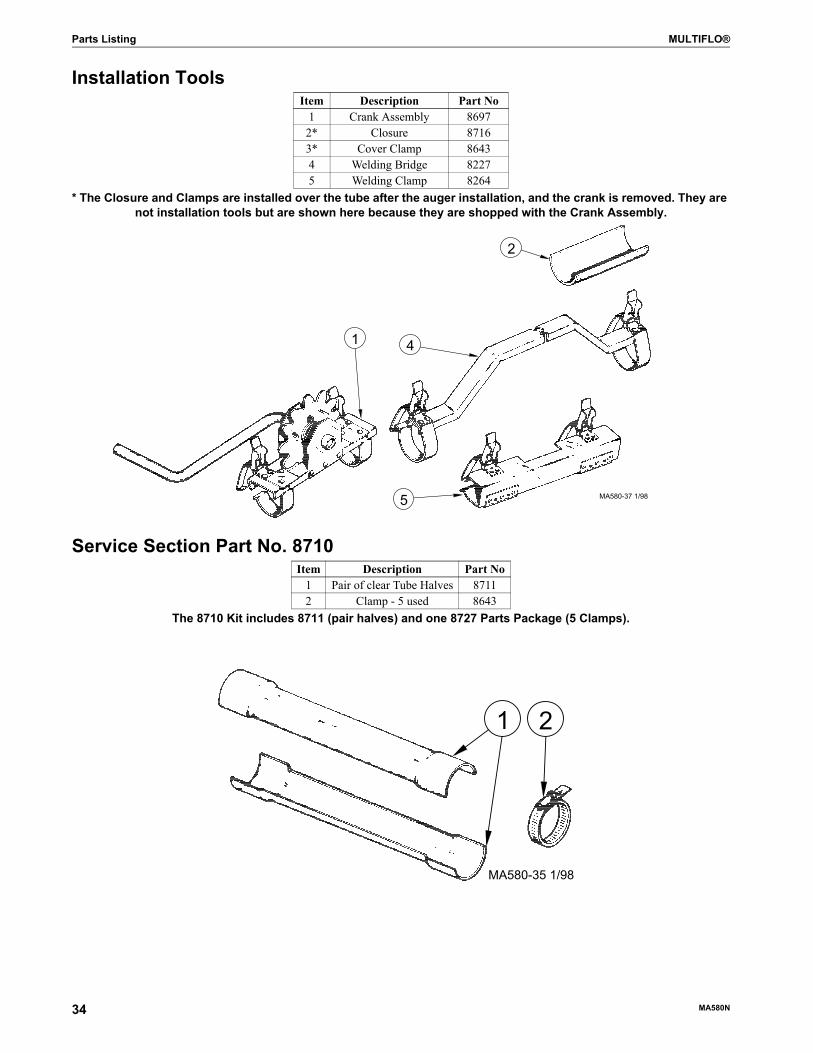
Parts Listing MULTIFLO®
Installation Tools
* The Closure and Clamps are installed over the tube after the auger installation, and the crank is removed. They are not installation tools but are shown here because they are shopped with the Crank Assembly.
Service Section Part No. 8710
The 8710 Kit includes 8711 (pair halves) and one 8727 Parts Package (5 Clamps).
Item Description Part No1 Crank Assembly 86972* Closure 87163* Cover Clamp 86434 Welding Bridge 82275 Welding Clamp 8264
Item Description Part No1 Pair of clear Tube Halves 87112 Clamp - 5 used 8643
1 4
2
5 MA580-37 1/98
MA580-35 1/98
1 2
34
MA580N
MULTIFLO® Parts Listing
Line Components
*Components of 6372 Suspension Kit. Part No. 2128-0 can be ordered in lengths of 100’ (2128-100) or 250’ (2128-250)**(2) Auger Connectors and (4) Setscrews may be ordered under Part No 24961-2.
Item Description Part No Item Description Part No*1 Screw Hook 1214 **11 5/16-18 x 5/8” Set Screw (2 used) 24979*2 Chain *2128-0 12 180° Hardened Steel Elbow with
Clamp and Coupler46720
*3 “S” Hook 7234 Auger 7961MF 13 180° Hardened Steel Elbow 467195 Tube Clamp 7976 14 Adjustable Clamp 86436 10' PVC Tube 7955 15 90° Nylon Elbow Kit 479507 Boot Outlet Coupler 8555 16 Nylon Elbow Half 467798 Tube Connector 8029 17 Elbow Adapter 467789 PVC Elbow Coupler 39200
**10 Auger Connector 24724
MA580-36 5/2006
1416
1
2
3
4
5
6
7
8
91110
12
13
14
17
15
M
A580N 35
Trouble Shooting Guide MULTIFLO®
Trouble Shooting Guide
Problem Possible Cause Corrective ActionSystem will not run No power to the system Check circuits, fuses, and on-off switches on
equipment.Motor overloaded and
stoppedCheck for foreign material in line, push reset
button.System not calling for feed. Examine Control Unit Switch and Hopper Level
Control.Remove feed if plugged.
Defective motor Replace MotorMotor overloads after
running brieflyMotor too small Use recommended size motor for line length.
Low voltage (motor runs slow and overheats)
Check line voltage at motor, use adequate size wire in circuits.
Foreign object in auger (motor runs, stalls, no feed
conveyed)
Check auger line, pull auger to remove object
System overcharged, plugged Clean-out systemWet feed being conveyed or
allowed to stand in tubesClean auger and tube, avoid conveying wet feed or
empty line after each feeding.Motor defective (overheats
without load)Replace motor.
Motor runs, but auger does not run
Sheared pin in sprocket Replace damaged or lost pin.Broken power unit pinion Examine pinion on motor shaft.
Replace BOTH gearhead and pinion of pinion is damaged.
Auger wears holes in straight tubes
Auger kinked or poorly brazed
See Auger Brazing section.
Excessive operating time empty
Do not allow system to operate empty.
Elbows wear out Auger is over stretched Lengthen auger.Auger ran dry Do not allow system to operate empty.Line not level Level lines.
Auger runs erratically
Auger to lone Shorten auger.Auger kinked or poorly
brazedSee Auger Brazing section.
Equipment not installed within the capabilities of
system
Refer to this manual fro approved system installations.
Excessive Auger vibration and noise
System operated too often without feed (auger tubes
have been scored by auger)
Do not allow the system to run empty.Replace tubes.
Be sure auger is correct length.Tube inadequately supported Support Tubes every 5’ (1.5 m) or closer.
Fill system short cycles
Check for correct rpm of gearhead on fill system
Install correct rpm of gearhead.
Switch failure causing system to circulate
repair or replace malfunctioning switch.
Motor Stalls or oscillates
System overcharged, plugged Clean-out system.
36
MA580N
MULTIFLO® Trouble Shooting Guide
Page left blank for notes.
M
A580N 37
MADE TO WORK.
BUILT TO LAST.®
Contact your nearby Chore-Time distributor or representative for additional parts and information.
CTB Inc.P.O. Box 2000 • Milford, Indiana 46542-2000 • U.S.A.
Phone (574) 658-4101 • Fax (877) 730-8825E-mail: [email protected] • Internet: http//www.choretime.com
Printed in the U.S.A.