installation and parts replacement manual for dodge
TRANSCRIPT
1
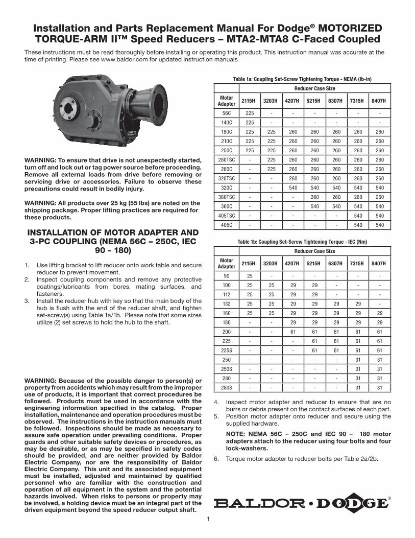
WARNING: To ensure that drive is not unexpectedly started, turn off and lock out or tag power source before proceeding. Remove all external loads from drive before removing or servicing drive or accessories. Failure to observe these precautions could result in bodily injury.
WARNING: All products over 25 kg (55 lbs) are noted on the shipping package. Proper lifting practices are required for these products.
INSTALLATION OF MOTOR ADAPTER AND 3-PC COUPLING (NEMA 56C – 250C, IEC
90 - 180)
1. Use lifting bracket to lift reducer onto work table and secure reducer to prevent movement.
2. Inspect coupling components and remove any protective coatings/lubricants from bores, mating surfaces, and fasteners.
3. Install the reducer hub with key so that the main body of the hub is flush with the end of the reducer shaft, and tighten set-screw(s) using Table 1a/1b. Please note that some sizes utilize (2) set screws to hold the hub to the shaft.
WARNING: Because of the possible danger to person(s) or property from accidents which may result from the improper use of products, it is important that correct procedures be followed. Products must be used in accordance with the engineering information specified in the catalog. Proper installation, maintenance and operation procedures must be observed. The instructions in the instruction manuals must be followed. Inspections should be made as necessary to assure safe operation under prevailing conditions. Proper guards and other suitable safety devices or procedures, as may be desirable, or as may be specified in safety codes should be provided, and are neither provided by Baldor Electric Company, nor are the responsibility of Baldor Electric Company. This unit and its associated equipment must be installed, adjusted and maintained by qualified personnel who are familiar with the construction and operation of all equipment in the system and the potential hazards involved. When risks to persons or property may be involved, a holding device must be an integral part of the driven equipment beyond the speed reducer output shaft.
Installation and Parts Replacement Manual For Dodge® MOTORIZED TORQUE-ARM II™ Speed Reducers – MTA2-MTA8 C-Faced Coupled
These instructions must be read thoroughly before installing or operating this product. This instruction manual was accurate at the time of printing. Please see www.baldor.com for updated instruction manuals.
Table 1a: Coupling Set-Screw Tightening Torque - NEMA (lb-in)
Reducer Case Size
Motor Adapter 2115H 3203H 4207H 5215H 6307H 7315H 8407H
56C 225 - - - - - -
140C 225 - - - - - -
180C 225 225 260 260 260 260 260
210C 225 225 260 260 260 260 260
250C 225 225 260 260 260 260 260
280TSC - 225 260 260 260 260 260
280C - 225 260 260 260 260 260
320TSC - - 260 260 260 260 260
320C - - 540 540 540 540 540
360TSC - - - 260 260 260 260
360C - - - 540 540 540 540
405TSC - - - - - 540 540
405C - - - - - 540 540
Table 1b: Coupling Set-Screw Tightening Torque - IEC (Nm)
Reducer Case Size
Motor Adapter 2115H 3203H 4207H 5215H 6307H 7315H 8407H
90 25 - - - - - -
100 25 25 29 29 - - -
112 25 25 29 29 - - -
132 25 25 29 29 29 29 -
160 25 25 29 29 29 29 29
180 - - 29 29 29 29 29
200 - - 61 61 61 61 61
225 - - - 61 61 61 61
225S - - - 61 61 61 61
250 - - - - - 31 31
250S - - - - - 31 31
280 - - - - - 31 31
280S - - - - - 31 31
4. Inspect motor adapter and reducer to ensure that are no burrs or debris present on the contact surfaces of each part.
5. Position motor adapter onto reducer and secure using the supplied hardware.
NOTE: NEMA 56C – 250C and IEC 90 – 180 motor adapters attach to the reducer using four bolts and four lock-washers.
6. Torque motor adapter to reducer bolts per Table 2a/2b.

2
Table 2a: Motor Adapter to Reducer Tightening Torque - NEMA
Motor Adapter Fastener Size Bolt Tightening Torque
56C 1/2-13 75 - 70 lb-ft (102 - 95 Nm)
140C 1/2-13 75 - 70 lb-ft (102 - 95 Nm)
180C 1/2-13 75 - 70 lb-ft (102 - 95 Nm)
210C 1/2-13 75 - 70 lb-ft (102 - 95 Nm)
250C 1/2-13 75 - 70 lb-ft (102 - 95 Nm)
280C / 280TSC 1/2-13 75 - 70 lb-ft (102 - 95 Nm)
320C / 320TSC 1/2-13 75 - 70 lb-ft (102 - 95 Nm)
360C / 360TSC 1/2-13 75 - 70 lb-ft (102 - 95 Nm)
405C / 405TSC 1/2-13 75 - 70 lb-ft (102 - 95 Nm)
Table 2b: Motor Adapter to Reducer Tightening Torque - IEC
Motor Adapter Fastener Size Bolt Tightening Torque
90 1/2-13 75 - 70 lb-ft (102 - 95 Nm)
100 1/2-13 75 - 70 lb-ft (102 - 95 Nm)
112 1/2-13 75 - 70 lb-ft (102 - 95 Nm)
132 1/2-13 75 - 70 lb-ft (102 - 95 Nm)
160 1/2-13 75 - 70 lb-ft (102 - 95 Nm)
180 1/2-13 75 - 70 lb-ft (102 - 95 Nm)
200 1/2-13 75 - 70 lb-ft (102 - 95 Nm)
225 1/2-13 75 - 70 lb-ft (102 - 95 Nm)
225S 1/2-13 75 - 70 lb-ft (102 - 95 Nm)
250 5/8-11 115 - 110 lb-ft (156 - 149 Nm)
250S 5/8-11 115 - 110 lb-ft (156 - 149 Nm)
280 5/8-11 115 - 110 lb-ft (156 - 149 Nm)
280S 5/8-11 115 - 110 lb-ft (156 - 149 Nm)
7. Install the motor hub with key so that the main body of the hub is flush with the end of the motor shaft. Do not tighten set-screw(s).
8. Insert elastomeric center element into the reducer coupling hub.
9. Lift the motor using lift-assist equipment, and align the jaws of both coupling hubs so that they will interlock when the motor is installed.
10. Install the motor by aligning motor tenon and reducer tenon and sliding the motor forward until it stops against the reducer flange.
11. Install and tighten the motor bolts. Torque motor bolts per Table 3a/3b.
Table 3a: Motor Bolt Tightening Torque - NEMA
NEMA Motor Frame Motor Bolt Bolt Tightening Torque
56C-140C 3/8-16 26 - 23 lb-ft (36 - 31 Nm)
180C 1/2-13 75 - 70 lb-ft (102 - 95 Nm)
210C 1/2-13 75 - 70 lb-ft (102 - 95 Nm)
250C 1/2-13 75 - 70 lb-ft (102 - 95 Nm)
280C / 280TSC 1/2-13 75 - 70 lb-ft (102 - 95 Nm)
320C / 320TSC 5/8-11 115 - 110 lb-ft (156 - 149 Nm)
360C / 360TSC 5/8-11 115 - 110 lb-ft (156 - 149 Nm)
405C / 405TSC 5/8-11 115 - 110 lb-ft (156 - 149 Nm)
Table 3b: Motor Bolt Tightening Torque - IEC
IEC Motor Frame Motor Bolt Bolt Tightening Torque
90 M10 39 - 36 lb-ft (53 - 50 Nm)
100 M12 68 - 65 lb-ft (92 - 90 Nm)
112 M12 68 - 65 lb-ft (92 - 90 Nm)
132 M12 68 - 65 lb-ft (92 - 90 Nm)
160 M16 158 - 155 lb-ft (214 - 210 Nm)
180 M16 158 - 155 lb-ft (214 - 210 Nm)
200 M16 158 - 155 lb-ft (214 - 210 Nm)
225 M16 158 - 155 lb-ft (214 - 210 Nm)
225S M16 158 - 155 lb-ft (214 - 210 Nm)
250 M16 158 - 155 lb-ft (214 - 210 Nm)
250S M16 158 - 155 lb-ft (214 - 210 Nm)
280 M16 158 - 155 lb-ft (214 - 210 Nm)
280S M16 158 - 155 lb-ft (214 - 210 Nm)
12. Look through the access hole on the motor adapter and verify that the coupling faces are in full contact with the elastomeric element – without any preload on the element.
13. Tighten the motor half set-screw. Torque set-screw(s) per Table 2a/2b.
14. Install the access hole plug(s) into motor adapter.
REDUCER HUB SET SCREW
REDUCER HUB
ELASTOMERIC ELEMENT
ACCESS HOLE PLUG
MOTOR ADAPTER
MOTOR HUB
MOTOR HUB SET SCREW
Figure 1 - Motor / Reducer Coupling Assembly
INSTALLATION OF MOTOR ADAPTER AND 3-PC COUPLING
(NEMA 280C – 405C, IEC 200 - 280)
1. Use lifting bracket to lift reducer onto work table and secure reducer to prevent movement.
2. Inspect motor adapter and reducer to ensure that are no burrs or debris present on the contact surfaces of each part.
3. Position motor adapter onto reducer and secure using the supplied hardware.
NOTE: The NEMA-280C motor adapter attaches to the reducer using four bolts and four lock-washers, and NEMA-320C-405C and IEC 200-280 motor adapters attach to the reducer using eight bolts and eight lockwashers.
4. Torque motor adapter to reducer bolts per Table 2a/2b. 5. Inspect coupling components and remove any protective
coatings/lubricants from bores, mating surfaces, and fasteners.
6. Install the reducer hub with key so that the main body of the hub is flush with the end of the reducer shaft, and tighten set-screw(s) using Table 1a/1b. Please note that some sizes utilize (2) set screws to hold the hub to the shaft.

3
7. Install the motor hub with key so that the main body of the hub is flush with the end of the motor shaft. Do not tighten set-screw(s).
8. Insert elastomeric center element into the reducer hub.9. Lift the motor using lift-assist equipment, and align the jaws
of both coupling hubs so that they will interlock when the motor is installed.
10. Install the motor by aligning motor tenon and reducer tenon and sliding the motor forward until it stops against the reducer flange.
11. Install and tighten the motor bolts. Torque motor bolts per Table 3a/3b.
12. Look through the access hole on the motor adapter and verify that the coupling faces are in full contact with the elastomeric element – without any preload on the element.
13. Tighten the motor half set-screw(s). Torque set-screw(s) per Table 1a/1b.
14. Install the access hole plug(s) into motor adapter.
INSTALLATION:
1. Use lifting bracket to lift reducer.2. Determine the running positions of the reducer. Although
the reducer may be operated in any position, the preferred mounting position is with the motor in the horizontal position (Position C) as shown in Figure 2. Position B is not recommended. Note that the reducer is supplied with seven plugs; four around the sides for horizontal installations, two plugs on the front face and one plug on the back face for vertical installations. These plugs must be arranged relative to the running positions as follows:
Horizontal Installations - Due to the many positions the MTA reducer may be oriented, the factory installed positions of the magnetic plug and breather may need to be relocated. The proper location for the magnetic plug is the hole closest to the bottom of the reducer. The filter breather is to be installed in the upper most hole. Of the two remaining plugs on the sides of the reducer, the highest plug is the minimum oil level plug as shown in Figure 2.
Vertical Installations - Install the filter breather plug in the hole provided in the upper face of the reducer housing. If space is restricted, the breather should be installed in the highest hole on the side of the reducer. Install a non-magnetic plug in the hole in the bottom face of the reducer. Do not install the magnetic plug in the bottom face. The magnetic plug should be located in the lowest level side hole. The highest level side plug is to be the minimum oil level plug.
HORIZONTAL MOUNTING
VERTICAL MOUNTING TYPICAL OIL HOLE LOCATIONS
POSITION F
POSITION DPOSITION CPOSITION A
POSITION E
OIL LEVEL (1)OIL LEVEL (2)
OIL LEVEL (4)
OIL LEVEL (6)
BREATHER
BREATHER
BREATHER
BREATHER
BREATHER
1
2
3
7 (BACK HOUSING FACE)
5 (BACK SIDE)
DRAIN
PLUG
OIL LEVEL (2)
6
DRAINDRAIN
PLUGPLUG
PLUG
PLUG
PLUG
DRAIN
DRAIN
4 (BACK SIDE)
Figure 2 - Mounting Positions, C-Face
The running position of the reducer in a horizontal application is not limited to the three positions shown in Figure 2. However, if running position is over 20° in position “D” or 5° in position “A” & “C”, either way from sketches, the oil level plug cannot be used safely to check the oil level, unless during the checking, the torque arm is disconnected and the reducer is swung to within 20° for position “D” or 5° for position “A” & “C” of the positions shown in Figure 2. Because of the many possible positions of the reducer, it may be necessary or desirable to make special adaptations using the lubrication filling holes furnished along with other standard pipe fittings, stand pipes and oil level gauges as required.
3. Mount reducer on driven shaft as follows:
For Taper Bushed Reducer: Mount reducer on driven shaft per instruction in bushing installation section of this manual.
Table 4 - Approximate Oil Volumes
CaseSize
Oil Volume in Quarts ①②③④⑤⑥ Oil Volume in Liters ①②③④⑤⑥
Horizontal Vertical Horizontal Vertical
A B C D E (Up) F (Down) A B C D E (Up) F (Down)
MTA2115H 4-1/4 ⑤ 3-5/8 7 5-3/8 5-5/8 3-3/4 ⑤ 3-1/2 6-5/8 5 5-3/8
MTA3203H 6-3/8 ⑤ 4-3/8 9-3/4 7-3/8 7-5/8 6 ⑤ 4-1/8 9-1/4 7 7-1/8
MTA4207H 8-1/4 ⑤ 6-3/4 13-1/8 9-1/4 9-5/8 7-7/8 ⑤ 6-3/8 12-3/8 8-7/8 9-1/8
MTA5215H 14 ⑤ 10-1/8 21 16 16-7/8 13-1/4 ⑤ 9-5/8 20 15-1/8 16
MTA6307H 18-3/8 ⑤ 15-3/8 30-1/8 23-1/2 24-7/8 17-3/8 ⑤ 14-1/2 28-1/2 22-1/4 23-1/2
MTA7315H 25 ⑤ 19-5/8 38-1/4 23-1/4 26-1/2 23-5/8 ⑤ 18-1/2 36-1/2 22 25-1/8
MTA8407H 29-1/8 ⑤ 22-5/8 52 31-3/4 31-3/4 27-5/8 ⑤ 21-3/8 49-1/4 30 30
① Refer to Figure 2 for mounting positions ② Oil quantity is approximate. Service with lubricant until oil runs out of oil level hole as indicated per drawings in Figure 2 ③ US measure: 1 quart = 32 fluid ounces =.94646 liters ④ Below 15 RPM output speed, oil level must be adjusted to reach the highest oil level plug. If reducer position is to vary from those shown in Figure 1, either more or less oil may
be required. Consult Dodge. ⑤ Position B not shown OR recommended, check with factory ⑥ For Position D - It is recommended to use “Position D Breather Kit” part number - 472300.

4
4. Reusing the existing reducer bolts, install the adapter plates in any suitable location on the flange of the reducer. Mount the rod assembly with the hardware included with the rod kit.
5. Install torque arm fulcrum on a flat and rigid support so that the torque arm will be approximately at right angles to the centerline through the driven shaft and the torque arm anchor screw, as shown in Figure 3.
90°
Tie Rod should be mounted at a 90° angle in relation to the center of the driven shaft.
Figure 3 - Tie Rod Mount
CAUTION: Unit is shipped without oil. Add proper amount of recommended lubricant before operating. Failure to observe this precaution could result in damage to or destruction of the equipment
6. Fill gear reducer with recommended lubricant. See Table 2.
MOTORIZED TORQUE-ARM II BUSHING INSTALLATION
The Dodge Motorized Torque-Arm II reducer is designed to fit both standard and short length driven shafts. The Standard Taper Bushings series is designed where shaft length is not a concern. The Short Shaft Bushing series is to be used where the driven shaft does not extend through the reducer. The Motorized Torque-Arm II reducer is designed to accept the standard Torque-Arm II bushing series.
Standard Taper Bushings:
1. One bushing assembly is required to mount the reducer on the driven shaft. An assembly consists of two tapered bushings, bushing screws and washers, two bushing backup plates and retaining rings, and necessary shaft key or keys. The driven shaft must extend through the full length of the reducer. If the driven shaft does not extend through the reducer do not use the standard tapered bushings; instead use the short shaft bushings as described in the Short Shaft Bushings section that follows. The minimum shaft length, as measured from the end of the shaft to the outer edge of the bushing flange (see Figure 4), is given in Table 6.
Table 5 – Oil Recommendations
Output RPMTorque-Arm II Reducer Size
MTA2115H MTA3203H MTA4207H MTA5215H MTA6307H MTA7315H MTA8407H
151 – 200 320 220 220 220 220 220 220
126 – 150 320 220 220 220 220 220 220
101 – 125 320 320 220 220 220 220 220
81 – 100 320 320 320 220 220 220 220
41 – 80 320 320 320 220 220 220 220
11 – 40 320 320 320 320 320 320 320
1 – 10 320 320 320 320 320 320 320
ISO Grades For Ambient Temperatures of 15˚F to 60˚F (-9ºC to 16ºC)
Output RPMTorque-Arm II Reducer Size
MTA2115H MTA3203H MTA4207H MTA5215H MTA6307H MTA7315H MTA8407H
151 – 200 220 150 150 150 150 150 150
126 – 150 220 150 150 150 150 150 150
101 – 125 220 220 150 150 150 150 150
81 – 100 220 220 220 150 150 150 150
41 – 80 220 220 220 150 150 150 150
11 – 40 220 220 220 220 220 220 220
1 – 10 220 220 220 220 220 220 220
Notes:1. Assumes auxiliary cooling where recommended in the catalog.2. Pour point of lubricant selected should be at least 10°F (6°C) lower than expected minimum ambient starting temperature.3. Extreme pressure (EP) lubricants are not necessary for average operating conditions. When properly selected for specific applications, TORQUE-ARM II backstops are
suitable for use with EP lubricants.4. Special lubricants may be required for food and drug industry applications where contact with the product being manufactured may occur. Consult a lubrication manufacturer’s
representative for his recommendations.5. For reducers operating in ambient temperatures between -22°F (-30°C) and 20°F (–6.6°C) use a synthetic hydrocarbon lubricant, 100 ISO grade or AGMA 3 grade (for
example, Mobil SHC 627). Above 125°F (51°C), consult DODGE Gear Application Engineering (864) 288-9050 for lubrication recommendation.6. Mobil SHC 630 Series oil is recommended for high ambient temperatures.

5
2. Install one bushing backup plate on the end of the hub and secure with the supplied retaining ring. Repeat procedure for other side.
3. Place one bushing, flange end first, onto the driven shaft and position per dimension “A”, as shown in Table 6. This will allow the bolts to be threaded into the bushing for future bushing and reducer removal.
4. Insert the output key in the shaft and bushing. For easy of installation, rotate the driven shaft so that the shaft keyseat is at the top position.
5. Mount the reducer on the driven shaft and align the shaft key with the reducer hub keyway. Maintain the recommended minimum distance “A” from the shaft bearing.
6. Insert the screws, with washers installed, in the unthreaded holes in the bushing flange and align with the threaded holes in the bushing backup plate. If necessary, rotate the bushing backup plate to align with the bushing screws. Tighten the screws lightly. If the reducer must be positioned closer than dimension “A”, place the screws with washers installed, in the unthreaded holes in the bushing before positioning reducer making sure to maintain at least 1/8” between the screw heads and the bearing.
7. Place the second tapered bushing in position on the shaft and align the bushing keyway with the shaft key. Align the unthreaded holes in the bushing with the threaded holes in the bushing backup plate. If necessary, rotate the bushing backup plate to align with the bushing holes. Insert bushing screws, with washers installed in the unthreaded holes in the bushing. Tighten screws lightly.
8. Alternately and evenly tighten the screws in the bushing nearest the equipment to the recommended torque given in Table 1. Repeat procedure on outer bushing.
Short Shaft Bushings:
1. One bushing assembly is required to mount the reducer on the driven shaft. An assembly consists of one long tapered bushing, one short tapered bushing, one tapered bushing wedge, bushing screws and washers, two bushing backup plates and two retaining rings, and necessary shaft key or keys. The driven shaft does not need to extend through the reducer for the short shaft bushing to operate properly. The minimum shaft length, as measured from the end of the shaft to the outer edge of the bushing flange (see Figure 3), is given in Table 1.
A
MINIMUM SHAFT LENGTH
A
MINIMUM SHAFT LENGTH
Figure 4 - Minimum Recommended Dimensions
Table 6 - Minimum Mounting Dimensions and Bolt Torques
Reducer Size Standard Taper BushingInch (mm)
Short Shaft Bushing Inch (mm)
MTA2115H 7.80 (198) 4.80 (122)
MTA3203H 8.55 (218) 5.46 (139)
MTA4207H 8.94 (227) 5.66 (144)
MTA5215H 10.33 (263) 6.35 (162)
MTA6307H 10.82 (275) 6.72 (171)
MTA7315H 11.87 (302) 7.62 (194)
MTA8407H 12.82 (325) 8.10 (206)
Bushing Screw Information and Minimum Clearance for Removal
Reducer Size Fastener Size Inch (mm)
Torque in Ft.-Lbs. (N-m) A Inch (mm)
MTA2115H 3/8 - 16 (M10 x 1.5) 26 – 23 (27 - 23) 1.20 (36)
MTA3203H 3/8 - 16 (M10 x 1.5) 26 – 23 (27 - 23) 1.20 (36)
MTA4207H 3/8 - 16 (M10 x 1.5) 26 – 23 (27 - 23) 1.48 (38)
MTA5215H 1/2 - 13 (M12 x 1.75) 75 - 67 (105 - 90) 1.81 (48)
MTA6307H 1/2 - 13 (M12 x 1.75) 75 - 67 (105 - 90) 1.81 (48)
MTA7315H 1/2 - 13 (M12 x 1.75) 75 - 67 (105 - 90) 2.06 (53)
MTA8407H 1/2 - 13 (M12 x 1.75) 75 - 67 (105 - 90) 2.06 (53)
2. The long bushing is designed to be installed from the side of the reducer opposite the driven equipment as shown in Figure 4. The long bushing when properly installed is designed to capture the end of the customer shaft that does not extend through the reducer. Normally the reducer would be mounted such that the input shaft extends from the side of the reducer opposite the driven equipment however the reducer design allows installation of the reducer to be mounted in the opposite direction.
3. Install the tapered bushing wedge into the hollow bore of the reducer from the same side as the long bushing will be installed. When installing the tapered bushing wedge into the reducer hub, install the flange end first so that the thin taper is pointing outwards towards the long bushing as shown in Figure 4. The wedge is properly installed when it snaps into place in the reducer hub.
Figure 5 - Short Shaft Bushing andOutput Hub Assembly
4. Align the tapered bushing wedge keyway with the reducer hub keyway. The keyway in the wedge is slightly wider than the keyway in the reducer hub allowing for easier installation.
5. Install one bushing backup plate on the end of the hub and secure with the supplied retaining ring. Repeat procedure for other side.

6
6. Install the short bushing; flange first, on the driven shaft and position per dimension “A”, as shown in Table 1. This will allow the bolts to be threaded into the bushing for future bushing and reducer removal.
7. Insert the output key in the shaft and bushing. For easy of installation, rotate the driven shaft so that the shaft keyseat is at the top position.
8. Mount the reducer on the driven shaft and align the shaft key with the reducer hub keyway. Maintain the recommended minimum distance “A” from the shaft bearing.
9. Insert the screws, with washers installed, in the unthreaded holes in the bushing flange and align with the threaded holes in the bushing backup plate. If necessary, rotate the bushing backup plate to align with the bushing screws. Tighten the screws lightly. If the reducer must be positioned closer than dimension “A”, place the screws with washers installed, in the unthreaded holes in the bushing before positioning reducer making sure to maintain at least 1/8” (3mm) between the screw heads and the bearing.
10. Place the long bushing in position on the shaft and align the bushing keyway with the shaft key. Use care to locate the long bushing with the tapered bushing wedge installed earlier. Align the unthreaded holes in the bushing with the threaded holes in the bushing backup plate. If necessary, rotate the bushing backup plate to align with the bushing holes. Insert bushing screws, with washers installed in the unthreaded holes in the bushing. Tighten screws lightly.
11. Alternately and evenly tighten the screws in the bushing nearest the equipment to the recommended torque given in Table 1. Repeat procedure on outer bushing.
Bushing Removal for Standard Taper or Short Shaft Bushings:1. Remove bushing screws.2. Place the screws in the threaded holes provided in the
bushing flanges. Tighten the screws alternately and evenly until the bushings are free on the shaft. For ease of tightening screws make sure screw threads and threaded holes in the bushing flanges are clean. If the reducer was positioned closer than the recommended minimum distance “A” as shown in Table 1, loosen the inboard bushing screws until they are clear of the bushing flange by 1/8” (3mm). Locate two (2) wedges at 180 degrees between the bushing flange and the bushing backup plate. Drive the wedges alternately and evenly until the bushing is free on the shaft.
3. Remove the outside bushing, the reducer, and then the inboard bushing.
LUBRICATIONNOTE: Because reducer is shipped without oil, it is necessary to add the proper amount of oil before operating reducer. Use a high-grade petroleum base rust and oxidation inhibited (R&O) gear oil - see tables. Follow instructions on reducer warning tags, and in the installation manual.
Under average industrial operating conditions, the lubricant should be changed every 2500 hours of operation or every 6 months, whichever occurs first. Drain reducer and flush with kerosene, clean magnetic drain plug and refill to proper level with new lubricant.
CAUTION: Too much oil will cause overheating and too little will result in gear failure. Check oil level regularly. Failure to observe this precaution could result in damage to the reducer.
Under extreme operating conditions, such as rapid rise and fall of temperature, dust, dirt, chemical particles, chemical fumes, or oil sump temperatures above 200°F (90ºC), the oil should be changed every 1 to 3 months, depending on severity of conditions.
GUIDELINES FOR MOTORIZED TORQUE-ARM II REDUCER LONG-TERM STORAGEDuring periods of long storage, or when waiting for delivery or installation of other equipment, special care should be taken to protect a gear reducer to have it ready to be in the best condition when placed into service.
By taking special precautions, problems such as seal leakage and reducer failure due to lack of lubrication, improper lubrication quantity, or contamination can be avoided. The following precautions will protect gear reducers during periods of extended storage:
Preparation:
1. Drain oil from the unit. Add a vapor phase corrosion inhibiting oil (VCI-105 oil by Daubert Chemical Co.) in accordance with Table 4.
2. Seal the unit airtight. Replace the vent plug with a standard pipe plug and wire the vent to the unit.
3. Cover all unpainted exterior parts with a waxy rust preventative compound that will keep oxygen away from the bare metal. (Non-Rust X-110 by Daubert Chemical Co. or equivalent)
4. The instruction manuals and lubrication tags are paper and must be kept dry. Either remove these documents and store them inside, or cover the unit with a durable waterproof cover which can keep moisture away.
5. Protect reducer from dust, moisture, and other contaminants by storing the unit in a dry area.
6. In damp environments, the reducer should be packed inside a moisture-proof container or an envelope of polyethylene containing a desiccant material. If the reducer is to be stored outdoors, cover the entire exterior with a rust preventative.
When placing the reducer into service:
1. Fill the unit to the proper oil level using a recommended lubricant. The VCI oil will not affect the new lubricant.
2. Clean the shaft extensions with petroleum solvents.3. Assemble the vent plug into the proper hole.4. Follow the installation instructions provided in this manual.
Table 7 - Quantities of VCI #105 Oil
Reducer Size Quantity (Ounces / Milliliter
MTA2115H 1 / 30
MTA3203H 1 / 30
MTA4207H 1 / 30
MTA5215H 2 / 59
MTA6307H 2 / 59
MTA7315H 3 / 89
MTA8407H 3 / 89
VCI #105 and #10 are interchangeable.VCI #105 is more readily available.

7
OIL VISCOSITY EQUIVALENCY CHART
2000
1000
800
600
500
400
300
200
100
80
60
50
40
30
20
10
8
6
5
4
3
2
70
60
50
40
30
20
10
8
5
4
9
7
6
1500
1000
680
460
320
220
150
100
68
8A
8
7
6
5
4
3
2
85W
250
140
90
80W
46
32
22
15
10
7
5
175W
3
2
300
200
150
100
80
70
60
50
40
35
32
400
500
600
800
1000
1500
2000
3000
4000
50006000
8000
10,000
cSt/40°C 100°C
cSt/ ISOVG
AGMAGRADES
GRADESGEAR OILS
SUS/100°F
SUS/210°F
SAE
KINEMATICVISCOSITIES
SAYBOLTVISCOSITIES
200
300
100
90
80
70
60
55
50
45
40VISCOSITIES CAN BERELATED HORIZONTALLYONLY.VISCOSITIES BASED ON96 VI SINGLE GRADEOILS.ISO ARE SPECIFIED AT40°C.AGMA ARE SPECIFIED AT40°C.SAE 75W, 80W, AND 85WSPECIFIED AT LOWTEMPERATURE. EQUIVALENTVISCOSITIES FOR 100°FAND 200°F ARE SHOWN.SAE 90 TO 250 SPECIFIEDAT 100°C.

8
BACKSTOPS
1. Remove backstop shaft cover and gasket, shown in Figure 5. These parts will not be reused. This cover is directly opposite the extended end of the input shaft.
2. Clean the face of the gearbox to remove any gasket material or contamination from the cover mounting surface. It is important that contamination not get into the gearbox or the backstop during the backstop installation/servicing process.
3. Face reducer looking at the side from which the cover was removed. Determine carefully the desired direction of free rotation. It is important that the direction be correctly determined because to reverse the direction after the backstop is installed, it is necessary to remove the backstop, turn it end-for-end and then reinstall it.
4. Match the arrow on the backstop inner race to the direction of free rotation for the desired shaft. Note that reversing the backstop end-for end changes the direction of the arrow. The shaft will rotate in the same direction as the arrow on the backstop.
5. If the backstop kit has a spacer ring included, install it onto the shaft first, adjacent to the bearing inner ring.
6. Install the backstop inner race and sprag cage assembly onto the shaft. DO NOT remove the cage from the inner race or the shipping strap from the sprag set at this time. Insert the key into the inner race and mating shaft keyway. These parts should slip onto the shaft easily, a light coating of oil may assist in assembly. Do not use a hammer to force the installation, damage can occur to the shaft and/or the backstop. Slide the race against the spacer or the shaft shoulder and install the retaining ring into the groove in the shaft. Only use the supplied key, as it is specifically designed for each backstop.
7. Apply a thin coating of RTV silicone onto the gearbox mating surface for the outer race (same as the cover area). It is important to apply the sealant around the fastener holes to prevent leakage. Do not allow excessive amounts of silicone to enter the gearbox or to be applied to other parts.
8. Install the outer race by gently rotating it opposite the shaft rotation while pressing lightly inwards. Do not force the outer race into position as backstop damage may occur. Once the outer race is well piloted onto the sprag set, remove the shipping strap from the sprag set by cutting it, being careful not to let the outer race back off the sprags. The outer race should slide easily into position with a slight turning motion. A light coating of oil on the race inner diameter may ease installation.
9. Align the fastener holes in the outer race with the mating holes in the gearbox. Use the supplied grade 5 fasteners and lock washers only. Torque the fasteners in an alternating pattern per Table 5.
Table 8 - Backstop Fastener Torque Values
Reducer Size Fastener Size Torque in Ft.-Lbs.(N-m)
MTA2115H 1/4-20 8 – 7 (12 - 9)
MTA3203H 1/4-20 8 – 7 (12 - 9)
MTA4207H 5/16-18 17 - 15 (23 - 20)
MTA5215H 5/16-18 17 - 15 (23 - 20)
MTA6307H 3/8-16 30 - 27 (41 - 36)
MTA7315H 3/8-16 30 - 27 (41 - 36)
MTA8407H 3/8-16 30 - 27 (41 - 36)
ARROW ON HUB OF INSTALLEDBACKSTOP MUST MATCHDIRECTION OF DESIRED
SHAFT ROTATION
BACKSTOP SHAFTCOVER GASKET
BACKSTOPSHAFT COVER
SPACER (IF APPLICABLE)
OUTER RACE
INNER RACE
RETAININGRING
BACKSTOPFASTENERS
BACKSTOPKEY
REDUCER WITHBACKSTOP INSTALLED
REDUCER WITHOUTBACKSTOP INSTALLED
Figure 6 - Backstop Assembly
9
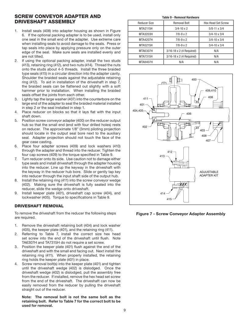
SCREW CONVEYOR ADAPTER AND DRIVESHAFT ASSEMBLY
1. Install seals (408) into adapter housing as shown in Figure 6. If the optional packing adapter is to be used, install only one seal in the small end of the adapter. Use extreme care when installing seals to avoid damage to the seals. Press or tap seals into place by applying pressure only on the outer edge of the seal. Make sure seals are installed evenly and are not tilted.
2. If using the optional packing adapter, install the two studs (413), retaining ring (412), and two nuts (414). Thread the nuts onto the studs about 4-5 threads. Install the three braided type seals (415) in a circular direction into the adapter cavity. Shoulder the braided seals against the adjustable retaining ring (412). To aid in installation of the driveshaft in step 7, the braided seals can be flattened out slightly with a soft hammer prior to installation. When installing the braided seals offset the joints from each other.
3. Lightly tap the large washer (407) into the counterbore on the large end of the adapter to seal the braided material installed in step 2 or the seal installed in step 1.
4. Place reducer on blocks so that it lays flat with the input shaft down.
5. Position screw conveyor adapter (400) on the reducer output hub so that the small end (end with four drilled holes) rests on reducer. The approximate 1/8” (3mm) piloting projection should locate in the output seal bore next to the auxiliary seal. Adapter projection should not touch the face of the gear case casting.
6. Place four adapter screws (409) and lock washers (410) through the adapter and thread into the reducer. Tighten the four cap screws (409) to the torque specified in Table 9.
7. Turn reducer onto its side. Use caution not to damage either type seals and install driveshaft through the adapter housing into the reducer. Line up the keyway in the driveshaft with the keyway in the reducer hub bore. Slide or gently tap key into reducer through the input shaft side of the output hub.
8. Install the retaining ring (411) into the screw conveyor wedge (402). Making sure the driveshaft is fully seated into the reducer, slide the wedge onto driveshaft.
9. Install keeper plate (401), driveshaft cap screw (404), and lockwasher (405). Torque to specifications in Table 9.
DRIVESHAFT REMOVAL
To remove the driveshaft from the reducer the following steps are required.
1. Remove the driveshaft retaining bolt (404) and lock washer (405), the keeper plate (401), and the retaining ring (411).
2. Referring to Table 7, install the correct size hex head set screw into the end of the driveshaft until flush. Note TA6307H and TA7315H do not require a set screw.
3. Position the keeper plate (401) flush against the end of the driveshaft and with the small end facing out. Next install the retaining ring (411). When properly installed, the retaining ring holds the keeper plate (401) in place.
4. Screw removal bolt(s) into the keeper plate (401) and tighten until the driveshaft wedge (402) is dislodged. Once the driveshaft wedge (402) is dislodged, pull the assembly free from the reducer. If installed, remove the hex head set screw from the end of the driveshaft. The driveshaft can now be easily removed from the reducer by pulling the driveshaft straight out of the reducer.
Note: The removal bolt is not the same bolt as the retaining bolt. Refer to Table 7 for the correct bolt to be used for removal.
Table 9 - Removal Hardware
Reducer Size Removal Bolt Hex Head Set Screw
MTA2115H 3/4-10 x 2 5/8-11 x 3/4
MTA3203H 7/8-9 x 2 3/4-10 x 3/4
MTA4207H 7/8-9 x 2 3/4-10 x 3/4
MTA5215H 7/8-9 x 2 3/4-10 x 3/4
MTA6307H 3/16-18 x 2 (4 Required) N/A
MTA7315H 3/16-18 x 2 (4 Required) N/A
MTA8407H N/A N/A
ADJUSTABLEADAPTER KIT
400
404,405
401
411
402
409,410
408
407
408
403
406
412413
415
414
Figure 7 - Screw Conveyor Adapter Assembly

10
REPLACEMENT OF PARTS
NOTE: Using tools normally found in a maintenance department, a Dodge Motorized Torque-Arm II speed reducer can be disassembled and reassembled by careful attention to the following instructions.
Cleanliness is very important to prevent the introduction of dirt into the bearings and other parts of the reducer. A tank of clean solvent, an arbor press, and equipment for heating bearings and gears (for shrinking these parts on shafts) should be available.
Our factory is prepared to repair reducers for customers who do not have proper facilities or who, for any reason, desire factory service.
The oil seals are contact lip seals. Considerable care should be used during disassembly and reassembly to avoid damage to the surface on which the seals rub.
Any sharp edges on the output hub should be covered with tape or paper before disassembly or reassembly. Also, be careful to remove any burrs or nicks on surfaces of the input shaft or output hub before disassembly or reassembly.
Ordering Parts: When ordering parts for reducer, specify reducer size number, reducer model number, part name, part number, and quantity.
It is strongly recommended that, when a pinion or gear is replaced, the mating pinion or gear is replaced also. If the large gear on the output hub must be replaced, it is recommended that an output hub assembly consisting of a gear assembled on a hub be ordered to ensure undamaged surfaces on the output hub where the output seals rub. However, if it is desired to use the old output hub, press the gear and bearing off and examine the rubbing surface under the oil seal carefully for possible scratching or other damage resulting from the pressing operation. To prevent oil leakage at the shaft oil seals, the smooth surface of the output hub must not be damaged.
If any parts must be pressed from a shaft or from the output hub, this should be done before ordering parts to make sure that none of the bearings or other parts are damaged in removal. Do not press against rollers or cage of any bearing.
Because old shaft oil seals may be damaged in disassembly, it is advisable to order replacements for these parts.
REMOVING REDUCER FROM SHAFT:
Removal of Tapered Bushings and Reducer:
1. Disconnect and remove torque arm rod from reducer adapter.
2. Remove bushing screws from bushings.3. Place the screws in the threaded holes provided in the
bushing flanges. Tighten the screws alternately and evenly until the bushings are free on the shaft. For ease of tightening screws, make sure screw threads and threaded holes in bushing flanges are clean. A tap can be used to clean out the threads. Use caution to use the proper size tap to prevent damage to the threads.
4. Remove the outside bushing, the reducer, and then the inboard bushing.
Disassembly:
1. Drain all oil from the reducer.2. Position the reducer on its side and remove the motor
assembly, front cover, and all housing bolts. Drive dowel pins from housing. Using the three pry slots around the periphery of the flange, gently separate the housing halves. Open housing evenly to prevent damage to the parts inside.
3. Lift input shaft, all gear assemblies, and bearing assemblies from housing. Remove all bolts retaining the bevel cartridge assembly and remove from housing.
4. Remove input gear from bevel pinion cartridge assembly.5. Disassemble bevel pinion cartridge.6. Remove all seals from housing. 7. Remove all bearings from shafts, hubs, and bevel pinion.
Be careful not to scratch or damage any assembly or seal area during bearing removal. The hub assembly can be disassembled for gear replacement but if scratching or grooving occurs on the hub, seal leakage will occur and the hub will need to be replaced.
Reassembly:
1. Output Hub Assembly: Heat gear to 325°F to 350°F (162ºC to 176ºC) to shrink onto hub. Heat bearings to 270°F to 290°F (132ºC to 143ºC) to shrink onto hub. Any damage to the hub surfaces where the oil seals rub will cause leakage, making it necessary to use a new hub.
2. Countershaft and Bevel Gear Assembly: Countershaft and pinion are integral. Press bevel gear and bearings on shaft. Press against inner race (not cage or rollers) of bearings.
3. Input Shaft Assembly: Shaft and pinion are integral. Press bearings on shaft. Press against inner race (not cage or rollers) of bearings.
4. Bevel Bearing Cartridge Assembly: Install the bearing cups into cartridge housing making sure bearing cups are fully seated against the bearing shoulders.4.1 Heat bearing cone to 270°F to 290°F (132ºC to 143ºC) to
shrink onto the bevel pinion shaft adjacent to the bevel pinion teeth. The bevel shaft and pinion are integral. If pressing is required, press against inner race (not cage or rollers) of bearing.
4.2 Slide the bevel pinion and bearing cone assembly into the bearing cartridge and set the cartridge assembly into a press with the pinion teeth facing down.
4.3 Using press, install outer bearing cone onto bevel pinion shaft using pressure per Table 8. The pressure listed is required to set correct preload. Do not press against the bevel pinion teeth as damage may occur. Press against flat surface on end of pinion only. The bevel pinion assembly should now have a slight preload.
4.4 Remove from press and install snap ring. At this time bevel assembly should be tight with no bearing end play.
4.5 Measure gap between snap ring and bearing.4.6 Remove snap ring and add shim equal to the measured
gap minus 0.0015” (.04mm) and reinstall snap ring.4.7 Using a rubber hammer, slightly tap the end of the pinion.
The bearings will slightly loosen. Verify the bearing end play setting per Table 8.
5. Place reducer housing with bevel cartridge provision on blocks to allow for protruding end of output hub during reassembly.
6. Drive the two dowel pins into place in the housing.7. Install bearing cup for bevel gear countershaft assembly into
the housing bore and install bevel gear assembly. Install the bevel pinion cartridge assembly into housing.

11
8. Lifting vertically upward on the bevel gear countershaft assembly, measure the movement of the countershaft assembly until the bevel gear locates tightly against the bevel pinion. Remove the bevel pinion cartridge from the housing and add shim under the bevel gear countershaft assembly per Table 8. This is the backlash setting for the bevel pinion and gear.
9. Reinstall bevel pinion cartridge assembly. Install first reduction gear and snap ring.
10. Install bearing cup on upper side of bevel gear countershaft assembly and set upper reducer housing in place. Measure and shim end play per Table 8.
11. Remove upper reducer housing and lightly coat the bevel pinion with red lead or suitable coating to check contact pattern on bevel gear.
12. Reinstall upper reducer housing and rotate input pinion 20-30 revolutions. This will transfer the red lead from the pinion to the gear teeth. Remove upper reducer housing and check tooth contact. If contact pattern is not correct, shim the bevel pinion cartridge until an acceptable pattern is achieved. This process may need to be repeated several times until correct pattern is obtained.
13. Install input shaft assembly in the housing and set input cover in place. Shim input assembly per Table 8.
14. Install remaining bearing cups into housing.15. Install and mesh output hub gear and bevel gear countershaft
assembly together and set in place in housing. Make sure bearing rollers (cones) are properly seated in their cups. Set bearing cups for opposite side housing in place on their rollers.
16. Making sure both reducer housings are clean, set opposite side housing into position onto the dowel pins and tap with a soft hammer (rawhide, not lead hammer) until housing bolts can be used to draw housing together. Make sure reducer shafts do not bind while tightening housing bolts.
17. Rotate the input pinion shaft and seat all remaining bearings with a soft hammer. Using a magnetic base and indicator, measure and record the end play of the output hub assembly. Remove upper housing and shim behind the bearing cup as required to achieve the correct bearing end play or preload per Table 8. Repeat this process and check end play until proper endplay is obtained. Note that the output shaft is preloaded. After endplay is determined, add the correct shim thickness to the end play reading to obtain the correct preload.
18. Remove upper reducer housing. Clean the flange surfaces on both housings, making sure not to nick or scratch flange face. Place a 1/8” (3mm) bead of Dow RTV732 sealant or equivalent on flange face (make sure RTV is placed around bolt holes and inside of flange face). Place opposite side housing into position onto the dowel pins and tap with a soft hammer (rawhide, not lead hammer) until housing bolts can be used to draw both housings together. Torque housing bolts per torque values listed in Table 9.
19. Install input, output, and auxiliary seals. Extreme care should be used when installing seals to avoid damage due to contact with sharp edges on the output hub. The possibility of damage and consequent oil leakage can be decreased by covering all sharp edges with tape prior to seal installation. Lightly coat the seal lips with Mobilith AW2 All-Purpose grease or equivalent. Seals should be pressed or tapped with a soft hammer evenly into place in the reducer housing, applying pressure only on the outer edge of the seals. A slight oil leakage at the seals may be evident during initial running, but should disappear unless seals have been damaged.
20. Install bushing backup plates and snap rings on taper bushed reducers.
Table 10 - Bearing Adjustment Tolerance & Backlash Setting
Reducer Size
Bearing Endplay ValuesInch (mm)
Input Countershaft Output Bevel
MTA2115H0.001-0.003
(0.025 - 0.076) Loose
0.0005-0.002.5(0.013 - 0.064)
Loose
0.002-0.004 (0.050 - 0.101)
Preload
0.0005-0.0015 (0.013 - 0.038)
Loose
MTA3203H0.001-0.003
(0.025 - 0.076) Loose
0.0005-0.002.5 (0.013 - 0.064)
Loose
0.002-0.004 (0.050 - 0.101)
Preload
0.0005-0.0015 (0.013 - 0.038)
Loose
MTA4207H0.001-0.003
(0.025 - 0.076) Loose
0.0005-0.002.5 (0.013 - 0.064)
Loose
0.002-0.004 (0.050 - 0.101)
Preload
0.0005-0.0015 (0.013 - 0.038)
Loose
MTA5215H0.001-0.003
(0.025 - 0.076) Loose
0.0005-0.002.5 (0.013 - 0.064)
Loose
0.002-0.004 (0.050 - 0.101)
Preload
0.0005-0.0015 (0.013 - 0.038)
Loose
MTA6307H0.001-0.003
(0.025 - 0.076) Loose
0.0005-0.002.5 (0.013 - 0.064)
Loose
0.002-0.004 (0.050 - 0.101)
Preload
0.0005-0.0015 (0.013 - 0.038)
Loose
MTA7315H0.001-0.003
(0.025 - 0.076) Loose
0.0005-0.002.5 (0.013 - 0.064)
Loose
0.002-0.004 (0.050 - 0.101)
Preload
0.0005-0.0015 (0.013 - 0.038)
Loose
MTA8407H0.001-0.003
(0.025 - 0.076) Loose
0.0005-0.002.5 (0.013 - 0.064)
Loose
0.002-0.004 (0.050 - 0.101)
Preload
0.0005-0.0015 (0.013 - 0.038)
Loose

12
Table 11 - Recommended Bolt Torque Values
Housing Bolt Recommended Torque Values
Reducer Size Fastener Size Torque in Ft.-Lbs. (N-m)
MTA2115H 3/8-16 30 – 27 (41 - 37)
MTA3203H 3/8-16 30 – 27 (41 - 37)
MTA4207H 1-2/13 75 - 70 (102 - 95)
MTA5215H 1-2/13 75 - 70 (102 - 95)
MTA6307H 1/2-13 75 - 70 (102 - 95)
MTA7315H 5/8-11 115 - 110 (156 - 149)
MTA8407H 5/8-11 115 - 110 (156 - 149)
Backstop Cover Bolt Recommended Torque Values
Reducer Size Fastener Size Torque in Ft.-Lbs. (N-m)
MTA2115H 1/4-20 8 – 7 (11 - 10)
MTA3203H 1/4-20 8 – 7 (11 - 10)
MTA4207H 5/16-18 17 - 15 (23 - 20)
MTA5215H 5/16-18 17 - 15 (23 - 20)
MTA6307H 3/8-16 30 - 27 (41 - 37)
MTA7315H 3/8-16 30 - 27 (41 - 37)
MTA8407H 3/8-16 30 - 27 (41 - 37)
Screw Conveyor Adapter Bolt Recommended Torque Values
Reducer Size Fastener Size Torque in Ft.-Lbs. (N-m)
MTA2115H 7/16-14 50 – 45 (68 - 61)
MTA3203H 1/2-13 75 - 70 (102 - 95)
MTA4207H 1/2-13 75 - 70 (102 - 95)
MTA5215H 5/8-11 115 - 110 (156 - 149)
MTA6307H 3/4-10 205 - 200 (278 - 271)
MTA7315H 3/4-10 205 - 200 (278 - 271)
MTA8407H N/A N/A
Screw Conveyor Drive Shaft Retainer Bolt Recommended Torque Values
Reducer Size Fastener Size Torque in Ft.-Lbs. (N-m)
MTA2115H 5/8-11 115 - 110 (156 - 149)
MTA3203H 3/4-10 205 - 200 (278 - 271)
MTA4207H 3/4-10 205 - 200 (278 - 271)
MTA5215H 3/4-10 205 - 200 (278 - 271)
MTA6307H 1”-8 215 - 210 (292 - 285)
MTA7315H 1”-8 215 - 210 (292 - 285)
MTA8407H N/A N/A
REPLACEMENT BEARING NUMBERS
Table 12–Dodge and Manufacturer Part Numbers for Replacement Bearings
ReducerSize
Output Hub Bearing – LH and RH Sides
Dodge Part Number Mfg. Part Number
MTA2115H 403003/402003 JLM714110/JLM714149
MTA3203H 903252/402268 493/498
MTA4207H 403016/402193 42584/42381
MTA5215H 403140/402050 JM822010/JM822049
MTA6307H 906250/906251 68712/68462
MTA7315H 403105/402147 36620/36690
MTA8407H 403105/402147 36620/36690
ReducerSize
Countershaft Bearing – LH and RH Side
Dodge Part Number Mfg. Part Number
MTA2115H 403000/402000 M86610/M86649
MTA3203H 472041/472040 HM89410/HM89449
MTA4207H 403005/304717 3820/3880
MTA5215H LH 403159/907260 HM807010/HM807046
MTA5215H RH 304841/304750 532X/539
MTA6307RH 451644/451643 612/623
MTA6307LH 411626-06-BE/411626-05BM 65500/65237
MTA7315H LH 411626-06-BE/411626-05-BM 65500/65237
MTA7315H RH 304802/402041 HM212011/HM212049
MTA8407H 403080/402114 742/745A
ReducerSize
Bevel Pinion Bearing
Dodge Part Number Mfg. Part Number
MTA2115H 403094/402283 15245/15117
MTA3203H INNER 304809/304710 25821/25877
MTA3203H OUTER 403000/402000 M86610/M86649
MTA4207H 454444/454445 24720/24780
MTA5215H INNER 402297 33209ASSY
MTA5215H OUTER 403005/304717 3820/3880
MTA6307H 402296/402297 33210ASSY/33209ASSY
MTA7315H 472168/472165 33212ASSY/33211ASSY
MTA8407H INNER 304802/402041 HM212011/HM212049
MTA8407H OUTER 472260/472259 JM511910/JM511946
ReducerSize
Input Shaft Bearing – LH and RH Sides
Dodge Part Number Mfg. Part Number
MTA2115H 304836/304743 M12610/M12648
MTA3203H 304836/304743 M12610/M12648
MTA4207H 403000/402000 M86610/M86649
MTA5215H 403000/402000 M86610/M86649
MTA6307H 402292/402293 HM88610/HM88649
MTA7315H 472041/472040 HM89410/HM89449
MTA8407H 403005/304717 3820/3880
NOTE: Bearing part numbers refer to Tapered Roller Bearing Cup/Cone combinations and apply to all ratios unless otherwise specified. For actual reducer ratios, refer to Table 12.

13
Parts for MTA2115H through MTA8407H Taper Bushed C-Face Reducers
4,5,6,7
232
24,25
200
201
1
21
14
44
203
9
34,36
204,205
39
11,12
59,60
6227
26
29
41
31,32
31,32
13
34,36
7065
64
5840
56,57
38
53
51
50
54
2855
10
22
19
100106,108
101
104
103
105
109,110
102
111,112107
409,410
403402
404,405
401
411 408
406
400
SCREW CONVEYORADAPTER ASSEMBLY
TORQUE ARMASSEMBLY
413
412
414415
408
407
OPTIONAL BACKSTOPASSEMBLY
600
ADJUSTABLEADAPTER KIT
63
69
67
66
68
61
Parts for MTA2115H through MTA8407H Taper Bushed C-Face ReducersRef. Description Qty. MTA2115H MTA3203H MTA4207H MTA5215H MTA6307H MTA7315H MTA8407H
1 Housing-LH 1 454262 472012 454388 454671 454514 472116 472213
2 Housing-RH 1 454266 472016 454392 454674 454518 472113 472216① RTV Sealant, Tube 1 415112-80-H 415112-80-H 415112-80-H 415112-80-H 415112-80-H 415112-80-H 415112-80-H
4 Housing Bolt 14 411412 411412 411460 411460 411460 411488 411488
5 Flat Washer 28 902241 902241 904241 904241 904241 907241 907241
6 Nut 14 407087 407087 407091 407091 407091 407093 407093
7 Lock-Washer 14 419011 419011 419013 419013 419013 419014 419014
8 ① Dowel Pin 2 304624 472048 304624 304624 304624 420145 420145
9 Backstop Shaft Cover 1 903279 904279 905279 906279 907279 910279 912279
10 Backstop Cover Gasket 1 903280 904280 905280 906280 907280 910280 912280
11 Backstop Cover Screw 6 417038 (6) 417038 (6) 417074 (8) 417074 (8) 417074 (8) 907281 (12) 907281 (12)
12 Lock-Washer 6 419045 (6) 419045 (6) 419046 (8) 419046 (8) 419046 (8) 419047 (12) 419047 (12)
13 Input Oil Seal 334271 334271 334273 334273 A73106 334274 334275
14 Output Oil Seal 2 902286 A73109 904286 905286 906286 907286 907286
15 ① Air Vent 1 900287 900287 904287 904287 904287 904287 904287
16 ① Bushing 1 N/A N/A 430079 430079 430079 N/A N/A
17 ① Oil Plug 2 430031 430031 430035 430035 430035 430035 430035
18 ① Magnetic Oil Plug 1 430060 430060 430064 430064 430064 430064 430064
19 Bearing Spacer 1 902594 903594 904594 905594 906594 907594 907594
21 Output Bearing Shim-As Required
.015” Shim 2 902263 903263 904263 905271 906263 907263 907263
.007” Shim 2 902265 903265 904265 905273 906265 907265 907265
.005” Shim 2 902264 903264 904264 905272 906264 907264 907264
22 Input Bearing Shim-As Required
.015” Shim 2 901271 901271 N/A N/A 454582 907271 907271
.010” Shim 2 N/A N/A 334327 334327 N/A N/A N/A
.007” Shim 2 901273 901273 N/A N/A 454581 907273 907273
.006” Shim 2 N/A N/A 334326 334326 N/A N/A N/A
.005” Shim 2 901272 901272 N/A N/A 454580 907272 907272
.003” Shim 2 N/A N/A 334325 334325 N/A N/A N/A

14
Parts for MTA2115H through MTA8407H Taper Bushed C-Face ReducersRef. Description Qty. MTA2115H MTA3203H MTA4207H MTA5215H MTA6307H MTA7315H MTA8407H23 Output Gear 1 902208 903208 904208 905208 906208 472133 472233
24 Output Bearing Cup 2 403003 903252 403016 403140 906250 403105 403105
25 Output Bearing Cone 2 402003 402268 402193 402050 906251 402147 402147
26 Output Hub 1 902230 903230 904230 905230 906230 907230 908230
27 Output Gear Key 1 901275 903275 904275 905275 906275 907275 908275
28 Input Pinion Key 443007 443007 443409 443409 443013 443182 338828
29 Input Pinion ⑤
17:1 Ratio 1 N/A 454290 N/A N/A N/A N/A 472238
18:1 Ratio 1 454290 N/A 454415 454415 N/A N/A N/A
19:1 Ratio 1 N/A N/A N/A N/A 454542 472138 N/A
21:1 Ratio 1 454291 454291 N/A 454416 N/A N/A N/A
22:1 Ratio 1 N/A N/A 454416 N/A 454543 472139 N/A
23:1 Ratio 1 N/A N/A N/A N/A N/A N/A 472239
24:1 Ratio 1 N/A N/A N/A N/A 454544 N/A N/A
25:1 Ratio 1 454292 454292 N/A 454417 N/A N/A N/A
26:1 Ratio 1 N/A N/A 454417 N/A N/A 472140 N/A
27:1 Ratio 1 N/A N/A N/A N/A N/A N/A 472240
29:1 Ratio 1 N/A 454293 N/A 454418 454545 472141 N/A
30:1 Ratio 1 454293 N/A 454418 N/A N/A N/A N/A
31:1 Ratio 1 N/A N/A N/A N/A N/A N/A 472241
32:1 Ratio 1 454294 454294 N/A N/A N/A N/A N/A
33:1 Ratio 1 N/A N/A N/A N/A N/A 472142 N/A
34:1 Ratio 1 N/A N/A 454419 454419 454546 N/A 472242
35:1 Ratio 1 N/A 454295 N/A N/A N/A N/A N/A
36:1 Ratio 1 454295 N/A N/A N/A N/A N/A N/A
38:1 Ratio 1 N/A 454296 N/A N/A N/A 472143 N/A
39:1 Ratio 1 454296 N/A N/A N/A 454547 N/A N/A
40:1 Ratio 1 N/A N/A N/A 454420 N/A N/A 472243
41:1 Ratio 1 N/A N/A 454420 N/A N/A N/A N/A
43:1 Ratio 1 N/A N/A N/A 454421 N/A N/A N/A
44:1 Ratio 1 454297 454297 454421 N/A N/A 472144 N/A
45:1 Ratio 1 N/A N/A N/A N/A 454548 N/A N/A
46:1 Ratio 1 N/A N/A N/A N/A N/A N/A 472244
47:1 Ratio 1 454298 454298 N/A N/A N/A N/A N/A
48:1 Ratio 1 N/A N/A N/A 454422 N/A N/A N/A
49:1 Ratio 1 N/A N/A 454422 N/A N/A N/A N/A
50:1 Ratio 1 N/A N/A N/A N/A 454546 472142 N/A
51:1 Ratio 1 454299 454299 N/A 454419 N/A 472146 472242
52:1 Ratio 1 N/A N/A 454419 N/A 454549 N/A N/A
29 53:1 Ratio 1 N/A N/A N/A N/A N/A N/A 472245
58:1 Ratio 1 454296 454296 N/A N/A N/A 472143 N/A
59:1 Ratio 1 N/A N/A N/A N/A 454547 N/A N/A
60:1 Ratio 1 N/A N/A N/A 454420 N/A N/A 472243
61:1 Ratio 1 N/A N/A 454420 N/A N/A N/A N/A
65:1 Ratio 1 N/A 454297 N/A 454421 N/A N/A N/A
66:1 Ratio 1 454297 N/A 454421 N/A N/A N/A N/A
67:1 Ratio 1 N/A N/A N/A N/A 454548 472145 N/A
69:1 Ratio 1 N/A N/A N/A N/A N/A N/A 472244
70:1 Ratio 1 N/A 454298 N/A N/A N/A N/A N/A
71:1 Ratio 1 454298 N/A N/A N/A N/A N/A N/A
72:1 Ratio 1 N/A N/A N/A 454422 N/A N/A N/A
74:1 Ratio 1 N/A N/A 454422 N/A N/A N/A N/A
76:1 Ratio 1 N/A 454299 N/A N/A N/A 472146 N/A
77:1 Ratio 1 454299 N/A N/A N/A N/A N/A N/A
79:1 Ratio 1 N/A N/A N/A N/A 454549 N/A 472245
31 Input Bearing Cup 2 304836 304836 403000 403000 402292 472041 403005
32 Input Bearing Cone 2 304743 304743 402000 402000 402293 472040 304717
34 Counter-Shaft Bearing Cup (LH) 1 403000 472041 403005 403159 411626-06-BE 411626-06-BE 403080
Counter-Shaft Bearing Cup (RH) 1 403000 472041 403005 304750 451644 304802 403080
36 Counter-Shaft Bearing Cone (LH) 1 402000 472040 304717 907260 411626-05-BM 411626-05-BM 402114
Counter-Shaft Bearing Cone (RH) 1 402000 472040 304717 304841 451643 402041 401114
38 First Stage Gear ④
17:1 Ratio 1 N/A 083538 N/A N/A N/A N/A 081761
18:1 Ratio 1 083538 N/A 083489 083489 N/A N/A N/A
19:1 Ratio 1 N/A N/A N/A N/A 083498 083491 N/A
21:1 Ratio 1 083510 083510 N/A 083452 N/A N/A N/A
22:1 Ratio 1 N/A N/A 083452 N/A 083494 081756 N/A
23:1 Ratio 1 N/A N/A N/A N/A N/A N/A 081750
24:1 Ratio 1 N/A N/A N/A N/A 081746 N/A N/A

15
Parts for MTA2115H through MTA8407H Taper Bushed C-Face ReducersRef. Description Qty. MTA2115H MTA3203H MTA4207H MTA5215H MTA6307H MTA7315H MTA8407H
25:1 Ratio 1 083480 083480 N/A 083439 N/A N/A N/A
26:1 Ratio 1 N/A N/A 083539 N/A N/A 081753 N/A
27:1 Ratio 1 N/A N/A N/A N/A N/A N/A 081757
29:1 Ratio 1 N/A 083475 N/A 083509 081722 081747 N/A
30:1 Ratio 1 083475 N/A 083509 N/A N/A N/A N/A
31:1 Ratio 1 N/A N/A N/A N/A N/A N/A 081754
32:1 Ratio 1 083434 083434 N/A N/A N/A N/A N/A
33:1 Ratio 1 N/A N/A N/A N/A N/A 081723 N/A
34:1 Ratio 1 N/A N/A 083481 083481 081718 N/A 081748
35:1 Ratio 1 N/A 083427 N/A N/A N/A N/A N/A
36:1 Ratio 1 083427 N/A N/A N/A N/A N/A N/A
38:1 Ratio 1 N/A 083420 N/A N/A N/A 081719 N/A
39:1 Ratio 1 083420 N/A N/A N/A 081743 N/A N/A
40:1 Ratio 1 N/A N/A N/A 083476 N/A N/A 081724
41:1 Ratio 1 N/A N/A 083476 N/A N/A N/A N/A
43:1 Ratio 1 N/A N/A N/A 083435 N/A N/A N/A
44:1 Ratio 1 083387 083387 083435 N/A N/A 081715 N/A
45:1 Ratio 1 N/A N/A N/A N/A 081740 N/A N/A
46:1 Ratio 1 N/A N/A N/A N/A N/A N/A 081720
47:1 Ratio 1 083413 083413 N/A N/A N/A N/A N/A
48:1 Ratio N/A N/A N/A 083428 N/A N/A N/A
49:1 Ratio 1 N/A N/A 083428 N/A N/A N/A N/A
50:1 Ratio 1 N/A N/A N/A N/A 081718 081737 N/A
51:1 Ratio 1 N/A 083382 N/A 083481 N/A 081741 081748
52:1 Ratio 1 N/A N/A 083481 N/A 081737 N/A 081716
53:1 Ratio 1 N/A N/A N/A N/A N/A N/A N/A
58:1 Ratio 1 083420 083420 N/A N/A N/A 081743 N/A
59:1 Ratio 1 N/A N/A N/A N/A 081743 N/A N/A
60:1 Ratio 1 N/A N/A N/A 083476 N/A N/A 081724
61:1 Ratio 1 N/A N/A 083476 N/A N/A N/A N/A
65:1 Ratio 1 N/A 083387 N/A 083435 N/A N/A N/A
66:1 Ratio 1 083387 N/A 083435 N/A N/A N/A N/A
67:1 Ratio 1 N/A N/A N/A N/A 081740 081740 N/A
69:1 Ratio 1 N/A N/A N/A N/A N/A N/A 081720
70:1 Ratio 1 N/A 083413 N/A N/A N/A N/A N/A
71:1 Ratio 1 083413 N/A N/A N/A N/A N/A N/A
72:1 Ratio 1 N/A N/A N/A 083428 N/A N/A N/A
74:1 Ratio 1 N/A N/A 083428 N/A N/A N/A N/A
76:1 Ratio 1 N/A 083382 N/A N/A N/A 081737 N/A
77:1 Ratio 1 083382 N/A N/A N/A N/A N/A N/A
79:1 Ratio 1 N/A N/A N/A N/A 081737 N/A 081716
39 Counter-Shaft Pinion 1 454303 472033 454429 454683 454555 472131 472231
40 First Stage Gear Key 1 094732 094732 102044 102044 690880 087699 087712
41 Counter-Shaft Bearing Shim-As Required
.015” Shim 2 454307 903267 905271 906271 907271 907271 904263
.007” Shim 2 454306 903269 905273 906273 907273 907273 904265
.005” Shim 2 454305 903268 905272 906272 907272 907272 904264
44 Auxiliary Output Seal 2 902236 903236 904236 905236 906236 907236 907236
50 Adapter Plate - NEMA
180TC 1 N/A N/A N/A N/A N/A N/A N/A
210TC 1 334571 334571 334571 334571 334571 334571 334571
250TC 1 334570 334570 334570 334570 334570 334570 334570
280TC 1 N/A N/A N/A N/A N/A N/A N/A
320TC 1 N/A N/A N/A N/A N/A N/A N/A
360TC 1 N/A N/A N/A 454450 454450 454450 454450
405TC 1 N/A N/A N/A N/A N/A 472171 472171
50 Adapter Plate - IEC 1
IEC 90 1 N/A N/A N/A N/A N/A N/A N/A
IEC 100 1 N/A N/A N/A N/A N/A N/A N/A
IEC 112 1 N/A N/A N/A N/A N/A N/A N/A
IEC 132 1 454602 454602 454602 454602 454602 N/A N/A
IEC 160 1 N/A N/A N/A N/A N/A N/A N/A
IEC 180 1 N/A N/A N/A N/A N/A N/A N/A
IEC 200 1 N/A N/A N/A N/A N/A N/A N/A
IEC 225 1 N/A N/A N/A 454595 454595 454595 454595
IEC 250 1 N/A N/A N/A N/A N/A N/A N/A
IEC 280 1 N/A N/A N/A N/A N/A N/A N/A

16
Parts for MTA2115H through MTA8407H Taper Bushed C-Face ReducersRef. Description Qty. MTA2115H MTA3203H MTA4207H MTA5215H MTA6307H MTA7315H MTA8407H51 Motor Adapter - NEMA
180TC 1 454401 454401 454401 454401 454401 454401 454401
210TC 1 454401 454401 454401 454401 454401 454401 454401
250TC 1 454401 454401 454401 454401 454401 454401 454401
280TC 1 N/A N/A 454404 454404 454404 454404 454404
320TC 1 N/A N/A 454409 454409 454409 454409 454409
360TC 1 N/A N/A N/A 454409 454409 454409 454409
405TC 1 N/A N/A N/A N/A N/A 454409 454409
51 Motor Adapter - IEC 1
IEC 90 1 454600 N/A N/A N/A N/A N/A N/A
IEC 100 1 454601 454601 N/A N/A N/A N/A N/A
IEC 112 1 454601 454601 454601 454601 N/A N/A N/A
IEC 132 1 454601 454601 454601 454601 454601 N/A N/A
IEC 160 1 454604 454604 454604 454604 454604 454604 N/A
IEC 180 1 N/A N/A 454604 454604 454604 454604 454604
IEC 200 1 N/A N/A 454606 454606 454606 454606 454606
IEC 225 1 N/A N/A N/A 454594 454594 454594 454594
IEC 225S N/A N/A N/A 454594 454594 454594 454594
IEC 250 1 N/A N/A N/A N/A N/A 472183 472183
IEC250S N/A N/A N/A N/A N/A 472183 472183
IEC 280 1 N/A N/A N/A N/A N/A 472183 472183
IEC 280S N/A N/A N/A N/A N/A 472183 472183
53 Motor Coupling - NEMA
180TC 1 454316 454316 454426 454426 454426 454426 454426
210TC 1 334286 334286 454427 454427 454427 454427 454427
250TC 1 334288 334288 454428 454428 454428 454428 454428
280TC 1 N/A N/A 454431 454431 454431 454431 454431
320TC 1 N/A N/A 454432 454432 454432 454432 454432
360TC 1 N/A N/A N/A 454566 454566 454566 454566
405TC 1 N/A N/A N/A N/A N/A 472172 472172
53 Motor Coupling - IEC 1
IEC 90 1 454610 N/A N/A N/A N/A N/A N/A
IEC 100 1 454611 454611 454614 N/A N/A N/A N/A
IEC 112 1 454611 454611 454614 454614 N/A N/A N/A
IEC 132 1 454612 454612 454615 454615 454615 454615 N/A
IEC 160 1 454613 454613 454616 454616 454616 454616 454616
IEC 180 1 N/A N/A 454617 454617 454617 454617 454617
IEC 200 1 N/A N/A 454618 454618 454618 454618 454618
IEC 225 1 N/A N/A N/A 454619 454619 454619 454619
IEC 225S 1 N/A N/A N/A 454618 454618 454618 454618
IEC 250 1 N/A N/A N/A N/A N/A 472186 472186
IEC 250S 1 N/A N/A N/A N/A N/A 472189 472189
IEC 280 1 N/A N/A N/A N/A N/A 472184 472184
IEC 280S N/A N/A N/A N/A N/A 472186 472186
54 Reducer Coupling - NEMA
180TC 1 454315 454315 454425 454425 454563 454563 454563
210TC 1 454315 454315 454425 454425 454563 454563 454563
250TC 1 454315 454315 454425 454425 454563 454563 454563
280TC 1 N/A N/A 454425 454425 454563 454563 454563
320TC 1 N/A N/A 454433 454433 454564 454564 454564
360TC 1 N/A N/A N/A 454433 454564 454564 454564
405TC 1 N/A N/A N/A N/A N/A 472173 472263
54 Reducer Coupling - IEC 1
IEC 90 1 454315 N/A N/A N/A N/A N/A N/A
IEC 100 1 454315 454315 454425 N/A N/A N/A N/A
IEC 112 1 454315 454315 454425 454425 N/A N/A N/A
IEC 132 1 454315 454315 454425 454425 454563 454427 N/A
IEC 160 1 454315 454315 454425 454425 454563 454427 454568
IEC 180 1 N/A N/A 454425 454425 454563 454427 454568
IEC 200 1 N/A N/A 454433 454433 454564 472191 454567
IEC 225 1 N/A N/A N/A 454433 454564 472191 454567
IEC 225S 1 N/A N/A N/A 454433 454564 472191 454567
IEC 250 1 N/A N/A N/A N/A N/A 472173 472263
IEC 250S 1 N/A N/A N/A N/A N/A 472173 472263
IEC 280 1 N/A N/A N/A N/A N/A 472173 472263
IEC 280S 1 N/A N/A N/A N/A N/A 472173 472263
17
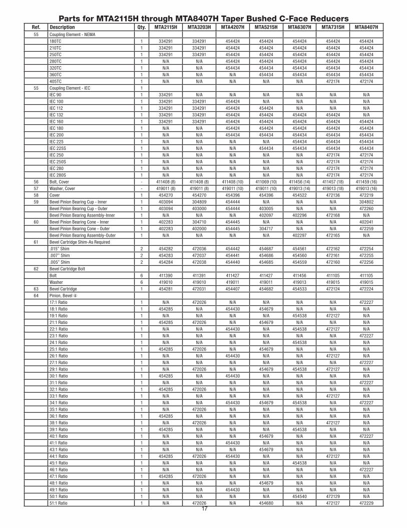
Parts for MTA2115H through MTA8407H Taper Bushed C-Face ReducersRef. Description Qty. MTA2115H MTA3203H MTA4207H MTA5215H MTA6307H MTA7315H MTA8407H55 Coupling Element - NEMA
180TC 1 334291 334291 454424 454424 454424 454424 454424
210TC 1 334291 334291 454424 454424 454424 454424 454424
250TC 1 334291 334291 454424 454424 454424 454424 454424
280TC 1 N/A N/A 454424 454424 454424 454424 454424
320TC 1 N/A N/A 454434 454434 454434 454434 454434
360TC 1 N/A N/A N/A 454434 454434 454434 454434
405TC 1 N/A N/A N/A N/A N/A 472174 472174
55 Coupling Element - IEC 1
IEC 90 1 334291 N/A N/A N/A N/A N/A N/A
IEC 100 1 334291 334291 454424 N/A N/A N/A N/A
IEC 112 1 334291 334291 454424 454424 N/A N/A N/A
IEC 132 1 334291 334291 454424 454424 454424 454424 N/A
IEC 160 1 334291 334291 454424 454424 454424 454424 454424
IEC 180 1 N/A N/A 454424 454424 454424 454424 454424
IEC 200 1 N/A N/A 454434 454434 454434 454434 454434
IEC 225 1 N/A N/A N/A N/A 454434 454434 454434
IEC 225S 1 N/A N/A N/A 454434 454434 454434 454434
IEC 250 1 N/A N/A N/A N/A N/A 472174 472174
IEC 250S 1 N/A N/A N/A N/A N/A 472174 472174
IEC 280 1 N/A N/A N/A N/A N/A 472174 472174
IEC 280S 1 N/A N/A N/A N/A N/A 472174 472174
56 Bolt, Cover - 411408 (8) 411408 (8) 411408 (10) 411069 (10) 411456 (14) 411457 (18) 411459 (16)
57 Washer, Cover - 419011 (8) 419011 (8) 419011 (10) 419011 (10) 419013 (14) 419013 (18) 419013 (16)
58 Cover 1 454270 454270 454396 454396 454522 472136 472219
59 Bevel Pinion Bearing Cup - Inner 1 403094 304809 454444 N/A N/A N/A 304802
Bevel Pinion Bearing Cup - Outer 1 403094 403000 454444 403005 N/A N/A 472260
Bevel Pinion Bearing Assembly-Inner 1 N/A N/A N/A 402097 402296 472168 N/A
60 Bevel Pinion Bearing Cone - Inner 1 402283 304710 454445 N/A N/A N/A 402041
Bevel Pinion Bearing Cone - Outer 1 402283 402000 454445 304717 N/A N/A 472259
Bevel Pinion Bearing Assembly-Outer 1 N/A N/A N/A N/A 402297 472165 N/A
61 Bevel Cartridge Shim-As Required
.015” Shim 2 454282 472036 454442 454687 454561 472162 472254
.007” Shim 2 454283 472037 454441 454686 454560 472161 472255
.005” Shim 2 454284 472038 454440 454685 454559 472160 472256
62 Bevel Cartridge Bolt
Bolt 6 411390 411391 411427 411427 411456 411105 411105
Washer 6 419010 419010 419011 419011 419013 419015 419015
63 Bevel Cartridge 1 454281 472031 454407 454682 454533 472124 472224
64 Pinion, Bevel ④
17:1 Ratio 1 N/A 472026 N/A N/A N/A N/A 472227
18:1 Ratio 1 454285 N/A 454430 454679 N/A N/A N/A
19:1 Ratio 1 N/A N/A N/A N/A 454538 472127 N/A
21:1 Ratio 1 454285 472026 N/A 454679 N/A N/A N/A
22:1 Ratio 1 N/A N/A 454430 N/A 454538 472127 N/A
23:1 Ratio 1 N/A N/A N/A N/A N/A N/A 472227
24:1 Ratio 1 N/A N/A N/A N/A 454538 N/A N/A
25:1 Ratio 1 454285 472026 N/A 454679 N/A N/A N/A
26:1 Ratio 1 N/A N/A 454430 N/A N/A 472127 N/A
27:1 Ratio 1 N/A N/A N/A N/A N/A N/A 472227
29:1 Ratio 1 N/A 472026 N/A 454679 454538 472127 N/A
30:1 Ratio 1 454285 N/A 454430 N/A N/A N/A N/A
31:1 Ratio 1 N/A N/A N/A N/A N/A N/A 472227
32:1 Ratio 1 454285 472026 N/A N/A N/A N/A N/A
33:1 Ratio 1 N/A N/A N/A N/A N/A 472127 N/A
34:1 Ratio 1 N/A N/A 454430 454679 454538 N/A 472227
35:1 Ratio 1 N/A 472026 N/A N/A N/A N/A N/A
36:1 Ratio 1 454285 N/A N/A N/A N/A N/A N/A
38:1 Ratio 1 N/A 472026 N/A N/A N/A 472127 N/A
39:1 Ratio 1 454285 N/A N/A N/A 454538 N/A N/A
40:1 Ratio 1 N/A N/A N/A 454679 N/A N/A 472227
41:1 Ratio 1 N/A N/A 454430 N/A N/A N/A N/A
43:1 Ratio 1 N/A N/A N/A 454679 N/A N/A N/A
44:1 Ratio 1 454285 472026 454430 N/A N/A 472127 N/A
45:1 Ratio 1 N/A N/A N/A N/A 454538 N/A N/A
46:1 Ratio 1 N/A N/A N/A N/A N/A N/A 472227
47:1 Ratio 1 454285 472026 N/A N/A N/A N/A N/A
48:1 Ratio 1 N/A N/A N/A 454679 N/A N/A N/A
49:1 Ratio 1 N/A N/A 454430 N/A N/A N/A N/A
50:1 Ratio 1 N/A N/A N/A N/A 454540 472129 N/A
51:1 Ratio 1 N/A 472026 N/A 454680 N/A 472127 472229

18
Parts for MTA2115H through MTA8407H Taper Bushed C-Face ReducersRef. Description Qty. MTA2115H MTA3203H MTA4207H MTA5215H MTA6307H MTA7315H MTA8407H65 Gear, Bevel ④
17:1 Ratio 1 N/A 472025 N/A N/A N/A N/A 472226
18:1 Ratio 1 454286 N/A 454411 454677 N/A N/A N/A
19:1 Ratio 1 N/A N/A N/A N/A 454537 472126 N/A
21:1 Ratio 1 454286 472025 N/A 454677 N/A N/A N/A
22:1 Ratio 1 N/A N/A 454411 N/A 454537 472126 N/A
23:1 Ratio 1 N/A N/A N/A N/A N/A N/A 472226
24:1 Ratio 1 N/A N/A N/A N/A 454537 N/A N/A
25:1 Ratio 1 454286 472025 N/A 454677 N/A N/A N/A
26:1 Ratio 1 N/A N/A 454411 N/A N/A 472126 N/A
27:1 Ratio 1 N/A N/A N/A N/A N/A N/A 472226
29:1 Ratio 1 454286 472025 N/A 454677 454537 472126 N/A
30:1 Ratio 1 N/A N/A 454411 N/A N/A N/A N/A
31:1 Ratio 1 N/A N/A N/A N/A N/A N/A 472226
32:1 Ratio 1 454286 472025 N/A N/A N/A N/A N/A
33:1 Ratio 1 N/A N/A N/A N/A N/A 472126 N/A
34:1 Ratio 1 N/A N/A 454411 454677 454537 N/A 472226
35:1 Ratio 1 N/A 472025 N/A N/A N/A N/A N/A
36:1 Ratio 1 454286 N/A N/A N/A N/A N/A N/A
38:1 Ratio 1 N/A 472025 N/A N/A N/A 472126 N/A
39:1 Ratio 1 454286 N/A N/A N/A 454537 N/A N/A
40:1 Ratio 1 N/A N/A N/A 454677 N/A N/A 472226
41:1 Ratio 1 N/A N/A 454411 N/A N/A N/A N/A
43:1 Ratio 1 N/A N/A N/A 454677 N/A N/A N/A
44:1 Ratio 1 454286 472025 454411 N/A N/A 472126 N/A
45:1 Ratio 1 N/A N/A N/A N/A 454537 N/A N/A
46:1 Ratio 1 N/A N/A N/A N/A N/A N/A 472226
47:1 Ratio 1 454286 472025 N/A N/A N/A N/A N/A
48:1 Ratio 1 N/A N/A N/A 454677 N/A N/A N/A
49:1 Ratio 1 N/A N/A 454411 N/A N/A N/A N/A
50:1 Ratio 1 N/A N/A N/A N/A 454539 472128 N/A
51:1 Ratio 1 N/A 472025 N/A 454678 N/A 472126 472228
52:1 Ratio 1 N/A N/A 454413 N/A 454537 N/A N/A
53:1 Ratio 1 N/A N/A N/A N/A N/A N/A 472226
58:1 Ratio 1 454288 472027 N/A N/A N/A 472128 N/A
59:1 Ratio 1 N/A N/A N/A N/A 454539 N/A N/A
60:1 Ratio 1 N/A N/A N/A 454678 N/A N/A 472228
61:1 Ratio 1 N/A N/A 454413 N/A N/A N/A N/A
65:1 Ratio 1 N/A 472027 N/A 454678 N/A N/A N/A
66:1 Ratio 1 454288 N/A 454413 N/A N/A N/A N/A
67:1 Ratio 1 N/A N/A N/A N/A 454539 472128 N/A
69:1 Ratio 1 N/A N/A N/A N/A N/A N/A 472228
70:1 Ratio 1 N/A 472027 N/A N/A N/A N/A N/A
71:1 Ratio 1 454288 N/A N/A N/A N/A N/A N/A
72:1 Ratio 1 N/A N/A N/A 454678 N/A N/A N/A
74:1 Ratio 1 N/A N/A 454413 N/A N/A N/A N/A
76:1 Ratio 1 N/A 472027 N/A N/A N/A 472128 N/A
77:1 Ratio 1 454288 N/A N/A N/A N/A N/A N/A
79:1 Ratio 1 N/A N/A N/A N/A 454539 N/A 472228
66 Bevel Pinion Shim-As Required
.15mm Shim 2 N/A N/A 728403 728403 697044 797103 085034
.30mm Shim 2 094903 094903 N/A N/A N/A N/A N/A
.10mm Shim 2 094805 094805 728411 728411 306851 094794 725447
67 Washer, Bevel Pinion 1 093780 093780 053483 053483 190020 040141 654019
68 Retaining Ring 1 982956 982956 084851 084851 084667 N/A 084511
69 Retaining Ring 1 278712 278712 278716 278716 051296 084445 084445
70 Bevel Gear Key 1 443433 454275 454443 454684 454536 472176 472247
600 Backstop Assembly 1 903102 904102 905102 906102 907102 910102 912102
100 Torque-Arm Adapter Bracket 2 902500 902500 904500 905500 906500 909500 909500
Torque-Arm Rod Kit ② 1 242244 242244 244245 244245 247238 N/A N/A
101 ③ Torque-Arm Rod End 1 243245 243245 245245 245245 247239 272050 272050
102 ③ Torque-Arm Extension 1 243247 243247 245247 245247 247240 272052 272052
103 ③ Torque-Arm Turnbuckle 1 243246 243246 245246 245246 247246 272051 272051
104 ③ RH Nut 1 407095 407095 407097 407097 407099 407108 407108
105 ③ LH Nut 1 407244 407244 407246 407246 407248 407251 407251
106 Torque-Arm Bushing 1 243243 243243 245243 245243 247244 272046 272046
107 Torque-Arm Fulcrum 1 243249 243249 246249 246249 247248 272054 272054
108 Torque-Arm Bolt 1 411437 411437 411460 411460 411489 411520 411520
109 Torque-Arm Lock-Washer 1 419012 419012 419013 419013 419014 418024 419024

19
Parts for MTA2115H through MTA8407H Taper Bushed C-Face ReducersRef. Description Qty. MTA2115H MTA3203H MTA4207H MTA5215H MTA6307H MTA7315H MTA8407H110 Torque-Arm Nut 1 407089 407089 407091 407091 407093 407104 407104
111 Torque-Arm Bolt 1 411484 411484 411484 411484 411489 411524 411524
112 Torque-Arm Nut 1 407093 407093 407093 407093 407093 407104 407104
113 Lock-washer (Not Shown) 1 N/A N/A N/A N/A 419014 419024 419024
200 Back-Up Plate (Included In Bushing Kit) 2 243308 903301 904301 905301 906301 272037 908301
201 Bushing Kit Assembly - Standard Shaft
4-7/16” Bore N/A N/A N/A N/A N/A 907019 908020
4-3/16” Bore N/A N/A N/A N/A N/A 907021 908021
3-15/16” Bore N/A N/A N/A N/A N/A 907022 908022
3-7/16” Bore N/A N/A N/A N/A 906020 907023 908023
3-3/16” Bore N/A N/A N/A 905020 906021 907024 908024
3-0” Bore N/A N/A N/A 905021 906022 907025 908025
2-15/16” Bore N/A N/A N/A 905022 906023 907026 908026
2-7/8” Bore N/A N/A N/A 905023 906024 907027 N/A
2-11/16” Bore N/A N/A 904020 905024 906025 907028 N/A
2-1/2” Bore N/A N/A 904021 905025 906026 907029 N/A
2-7/16” Bore N/A N/A 904022 905026 906027 907030 N/A
2-3/8” Bore N/A 903020 904023 905027 906028 N/A N/A
2-1/4” Bore N/A 903021 904024 905028 906029 N/A N/A
2-3/16” Bore 902020 903022 904025 905029 906030 N/A N/A
2-1/8” Bore N/A 903023 904026 905030 N/A N/A N/A
2-0” Bore 902022 903024 904027 905031 N/A N/A N/A
1-15/16” Bore 902023 903025 904028 905032 N/A N/A N/A
1-7/8” Bore 902004 903026 904029 N/A N/A N/A N/A
1-3/4” Bore 902025 903027 904030 N/A N/A N/A N/A
1-11/16” Bore 902026 903028 904031 N/A N/A N/A N/A
1-5/8” Bore 902027 903029 N/A N/A N/A N/A N/A
1-1/2” Bore 902028 903060 N/A N/A N/A N/A N/A
1-7/16” Bore 902029 903061 N/A N/A N/A N/A N/A
1-3/8” Bore 902060 N/A N/A N/A N/A N/A N/A
1-15/16” Bore 902061 N/A N/A N/A N/A N/A N/A
203 Retaining Ring-Included In Bushing Kit 2 421109 903304 421107 421055 906304 421098 908304
204 Cap Screw-Included In Bushing Kit 6 902306 411408 411408 411456 411456 411457 411457
205 Lock-Washer-Included In Bushing Kit 6 419011 419011 419011 419013 419013 419013 419013
400 Screw Conveyor Adapter 1 902401 903401 904401 905401 906401 907401 N/A
401 Screw Conveyor Keeper Plate 1 902402 903402 904402 905402 906402 907402 N/A
402 Screw Conveyor Wedge 1 902403 903403 904403 905403 906403 907403 N/A
403 Screw Conveyor Drive Shaft
1-1/2” Shaft 1 902072 903072 N/A N/A N/A N/A N/A
1-1/2” Shaft, Stainless Steel 1 902080 903080 N/A N/A N/A N/A N/A
2” Shaft 1 902073 903073 904073 905073 N/A N/A N/A
2” Shaft, Stainless Steel 1 902081 903081 904081 905081 N/A N/A N/A
2-7/16” Shaft 1 902074 903074 904074 905074 906074 907074 N/A
2-7/16” Shaft, Stainless Steel 1 902082 903082 904082 905082 906082 907082 N/A
3” Shaft 1 902075 903075 904075 905075 906075 907075 N/A
3” Shaft, Stainless Steel 1 902083 903083 904083 905083 906083 907083 N/A
3-7/16” Shaft 1 N/A 903076 904076 905076 906076 907076 N/A
3-7/16” Shaft, Stainless Steel 1 N/A 903084 904084 905084 906084 907084 N/A
404 Retaining Bolt 1 411549 411551 411551 411551 411552 411552 N/A
405 Lock-Washer 1 419014 419016 419016 419016 419020 419020 N/A
406 Drive Shaft Key 1 902405 903405 904405 905405 906405 907405 N/A
407 Drive Shaft Washer 1 902404 903404 904404 905404 906404 907404 N/A
408 Seal 2 902411 903411 904411 905411 906411 907411 N/A
409 Bolt 4 411435 411456 411456 411483 411983 411493 N/A
410 Lock-Washer 4 419012 419013 419013 419014 419016 419016 N/A
411 Retaining Ring 1 902406 903406 904406 905406 906406 907406 N/A
412 Adjustable Packing Retainer 1 902413 903413 904413 905413 906413 907413 N/A
413 Adjustable Packing Gland Stud 2 400404 400404 400404 400404 400404 400404 N/A
414 Adjustable Packing Gland Nut 2 407202 407202 407202 407202 407202 407202 N/A
415 Sealing Rings 3 902416 903416 904416 905416 906416 907416 N/A
① Not shown on drawing.② Includes parts listed immediately below marked “③”.③ Makes up assembly under which it is listed.④ See Table 12 for actual ratio.

20
Table 12 - Actual Ratios
Reducer Size Actual Ratio Output Speed @ 1750
M2H77T 76.96 22.74
M2H71T 71.18 24.59
M2H66T 66.07 26.49
M2H58T 58.29 30.02
M2H51T 51.31 34.11
M2H47T 47.45 36.88
M2H44T 44.05 39.73
M2H39T 38.86 45.03
M2H36T 35.88 48.77
M2H32T 32.15 54.43
M2H30T 29.64 59.04
M2H25T 24.87 70.37
M2H21T 21.22 82.47
M2H18T 17.68 98.98
M3H76T 76.96 22.74
M3H70T 71.18 24.59
M3H65T 66.07 26.49
M3H58T 58.29 30.02
M3H51T 51.31 34.11
M3H47T 47.45 36.88
M3H44T 44.05 39.73
M3H38T 38.86 45.03
M3H35T 35.88 48.77
M3H32T 32.15 54.43
M3H29T 29.64 59.04
M3H25T 24.87 70.37
M3H21T 21.22 82.47
M3H17T 17.68 98.98
M4H74T 73.57 23.79
M4H66T 66.17 26.45
M4H61T 61.04 28.67
M4H52T 51.72 33.84
M4H49T 49.04 35.68
M4H44T 44.11 39.67
M4H41T 40.70 43.00
M4H34T 34.48 50.75
M4H30T 30.05 58.24
M4H26T 25.57 68.44
M4H22T 21.82 80.20
M4H18T 17.89 97.82
M5H72T 71.98 24.31
M5H65T 64.74 27.03
M5H60T 59.73 29.30
M5H51T 50.61 34.58

21
Table 12 - Actual Ratios
Reducer Size Actual Ratio Output Speed @ 1750
M5H48T 47.99 36.47
M5H43T 43.16 40.55
M5H40T 39.82 43.95
M5H34T 33.74 51.87
M5H29T 29.41 59.50
M5H25T 25.02 69.94
M5H21T 21.35 81.97
M5H18T 17.50 100.00
M6H79T 78.53 22.28
M6H67T 66.92 26.15
M6H59T 59.05 29.64
M6H52T 52.35 33.43
M6H50T 50.26 34.82
M6H45T 44.61 39.23
M6H39T 39.37 44.45
M6H34T 33.51 52.22
M6H29T 29.03 60.28
M6H24T 24.43 71.63
M6H22T 22.04 79.40
M6H19T 18.95 92.35
M7H76T 76.46 22.89
M7H67T 66.57 26.29
M7H58T 57.58 30.39
M7H51T 50.97 34.33
M7H50T 50.22 34.85
M7H44T 44.38 39.43
M7H38T 38.39 45.58
M7H33T 33.48 52.27
M7H29T 28.65 61.08
M7H26T 25.66 68.20
M7H22T 21.74 80.50
M7H19T 18.77 93.23
M8H79T 78.80 22.21
M8H69T 68.53 25.54
M8H60T 60.13 29.10
M8H53T 52.53 33.31
M8H51T 50.85 34.41
M8H46T 45.69 38.30
M8H40T 40.09 43.65
M4H34T 33.90 51.62
M4H31T 30.76 56.89
M4H27T 26.82 65.25
M4H23T 22.77 76.86
M8H17T 17.43 100.40

22
Supplemental InstructionsFor the Installation, Operation
And Maintenance of
ATEX ApprovedMotorized Torque-Arm II Shaft Mount Reducers (Zone 1)
Sizes MTA2115 – MTA8407
PREFACE
The products described in this manual are manufactured by Baldor Electric Company A Member of ABB Group, Greenville, SC 29615 USA.
This manual (combined with MN1695) is intended to provide basic information on the safe operation and maintenance of ATEX approved Motorized Torque-Arm II shaft mount reducers. These instructions do not cover all details or variations in equipment nor provide every possible contingency or hazard to be met in connection with installation, operation, and maintenance. Should further information be desired or should particular problems arise which are not covered in the manual, the matter should be referred to your local Baldor Electric Company A Member of ABB Group representative.
The reducer was manufactured under the guidelines of the ATEX directive 94/9/EC.
Torque-Arm II reducers are suitable for ATEX Category 2 and M2, Group II and I, for gas and dust environments and are also suitable for ATEX Category 3 for all gas or dust environments with ignition temperatures higher than T4 = 135°C (275°F).
Typical reducer marking is contained on a certification plate similar to the following:
ATTENTION
The reducer is designed to operate with a surface temperature at or below 93°C (200°F). Failure to operate the reducer properly can cause this maximum surface temperature to be exceeded. If applied in a Division 1 or Zone 1 environment this excessive temperature may cause ignition of hazardous materials.
The use of supplemental cooling devices such as a shaft-mounted cooling fan or heat exchanger may be required to ensure operating temperature below 93°C (200°F) if indicated by catalog selection tables or if the reducer is operated at ambient temperatures above 27°C (80°F). Proper use of supplemental cooling, if provided, and avoidance of undesirable operating conditions is required.
ABNORMAL CONDITIONS
Operating the reducer under any of the following conditions can cause higher than normal operating temperatures:
1. reducer load exceeding nameplate ratings2. ambient temperatures above nameplate rating3. inadequate cooling4. operation above maximum nameplate speed5. insufficient amount or improper type of lubricant
For instructions on receiving and handling, installation, operation, maintenance and repair, and service refer to manual MN1695.
MOTORIZED TORQUE-ARM II SPEED REDUCER
PARTNUMBER
RATIO
HP AT MAX INPUT RPM
OIL QTY
QTS
SERVICE PER INSTRUCTION MANUAL
RATINGCLASS I
Tamb -30°C to +50°C1 M2/SIRA 12 ATEX 6164
R
ME MB E R OF
000001S
WEIGHT
POS. BU.S.
REFILL EVERY 6 MONTHS, INSPECT OIL OFTENDRAIN, FLUSH, CLEAN MAGNETIC PLUG AND
U.S.PATENT 5951198PATENTED PROJECTED
OTHER PATENTS PENDING
II 2 GD ck T4WARNING: an explosive atmospheremay be present
Do not open when
MFG. BY BALDOR ELEC CO/FT SMITH, AR 72901 USA
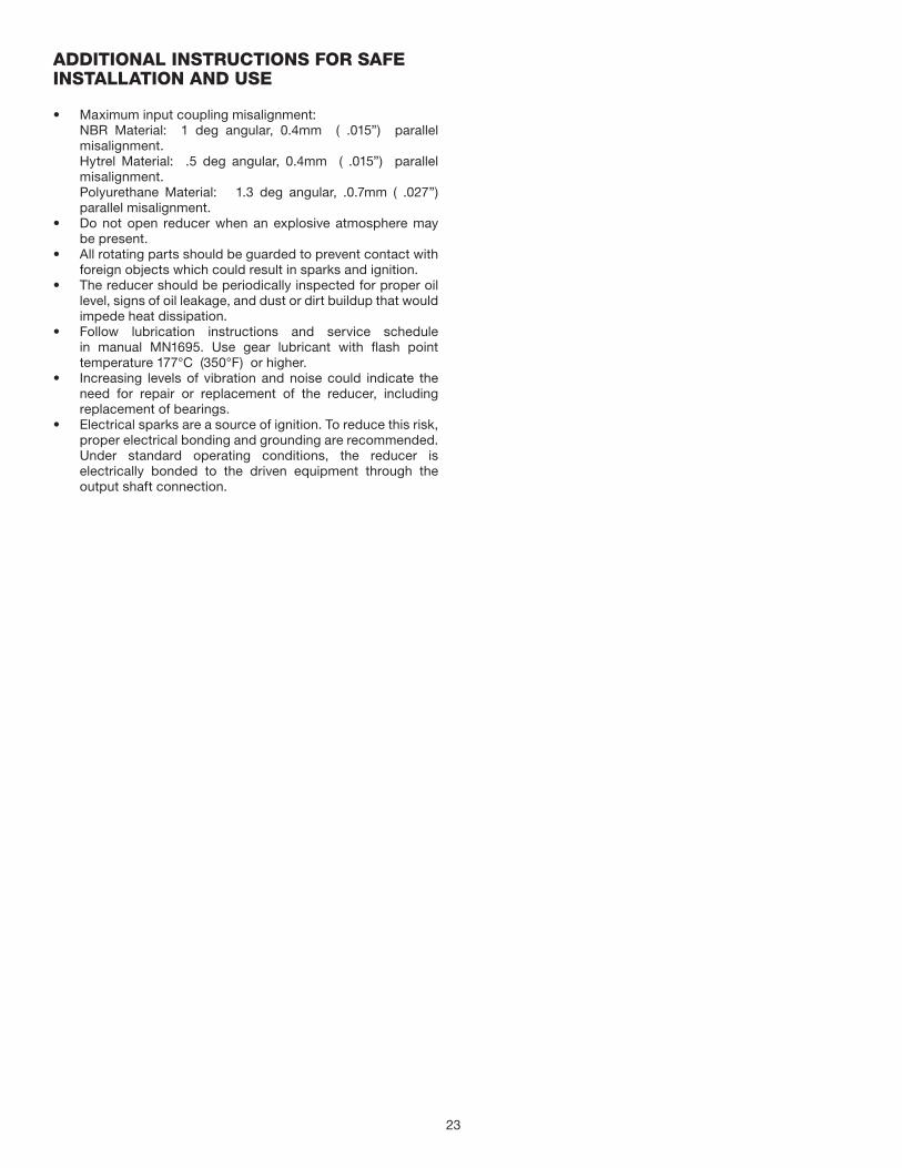
23
ADDITIONAL INSTRUCTIONS FOR SAFE INSTALLATION AND USE
• Maximum input coupling misalignment:NBR Material: 1 deg angular, 0.4mm ( .015”) parallel misalignment.Hytrel Material: .5 deg angular, 0.4mm ( .015”) parallel misalignment.Polyurethane Material: 1.3 deg angular, .0.7mm ( .027”) parallel misalignment.
• Do not open reducer when an explosive atmosphere may be present.
• All rotating parts should be guarded to prevent contact with foreign objects which could result in sparks and ignition.
• The reducer should be periodically inspected for proper oil level, signs of oil leakage, and dust or dirt buildup that would impede heat dissipation.
• Follow lubrication instructions and service schedule in manual MN1695. Use gear lubricant with flash point temperature 177°C (350°F) or higher.
• Increasing levels of vibration and noise could indicate the need for repair or replacement of the reducer, including replacement of bearings.
• Electrical sparks are a source of ignition. To reduce this risk, proper electrical bonding and grounding are recommended. Under standard operating conditions, the reducer is electrically bonded to the driven equipment through the output shaft connection.

P.O. Box 2400, Fort Smith, AR 72902-2400 U.S.A., Ph: (1) 479.646.4711, Fax (1) 479.648.5792, International Fax (1) 479.648.5895
Dodge Product Support
6040 Ponders Court, Greenville, SC 29615-4617 U.S.A., Ph: (1) 864.297.4800, Fax: (1) 864.281.2433
www.baldor.com
© Baldor Electric CompanyMN1695
All Rights Reserved. Printed in USA.0715 Printshop 500*1695-0715*
Document Control Number: DOC-BEZ-DG-M12-B-EN.DOC 1 / 1
EC Declaration of ConformityThe undersigned, representing the following supplier-
Baldor Electric Company 5711 R. S. Boreham, Jr. Street Fort Smith, Arkansas 72901 USAherewith declare that the Products
MTA Range of Reduction Gearboxes Product identification (brand and catalogue number/part number):
Sizes MTA2115H,MTA3203H,MTA4207H,MTA5215H,MTA6307H,MTA7315H, MTA8407H I M2 c k II 2GD c k T4 Tamb –30°C to +50°C (c-face clamp collar and c-face 3 piece coupling inputs) Tamb –30°C to +45°C (separate input) Sizes 38 and 48 II 2GD c k T4 Tamb –30°C to +50°C (c-face clamp collar and D-face 3 piece coupling inputs) Tamb -30°C to +45°C (separate input) Sira 12ATEX6164
are in conformity with the provisions of the following EC Directive(s) when installed in accordance with the installation instructions contained in the product documentation:94/9/EC ATEX
and that the standards and/or technical specifications referenced below have been applied:EN 13463-1:2009 Non - Electrical Equipment For Potentially Explosive Atmospheres -Method And
Requirements EN13463-5:2011 Non-Electrical Equipment Intended For Use In Potentially Explosive
Atmospheres - Part 5: Protection by constructional Safety ‘c’ EN13463-8:2008 Non-Electrical Equipment Intended For Use In Potentially Explosive
Atmospheres - Part 8: Protection by liquid immersion ‘k’ Supplier:Signature
Name: L. Evans Massey Position: Manager Standards and Certification :Date: 13 November-2013