installation and programming manual - scale service lake/m_88537-0802.pdf · and information...
TRANSCRIPT

EtherNet/IP™
Interface for 520, 820i ® and 920i ® Indicators
Installation andProgramming Manual
88537

Contents
About This Manual ................................................................................................................................... 11.0 Introduction.................................................................................................................................. 12.0 Installation ................................................................................................................................... 2
2.1 Installing the EtherNet/IP Interface . . . . . . . . . . . . . . . . . . . . . . . . . . . . . . . . . . . . . . . . . . . . . . . . . . . 22.1.1 Installing EtherNet/IP Option in the 820i/920i . . . . . . . . . . . . . . . . . . . . . . . . . . . . . . . . . . . . . . . . . . . . 22.1.2 Installing EtherNet/IP Option in the 520. . . . . . . . . . . . . . . . . . . . . . . . . . . . . . . . . . . . . . . . . . . . . . . . . 3
2.2 EtherNet/IP Network Connections . . . . . . . . . . . . . . . . . . . . . . . . . . . . . . . . . . . . . . . . . . . . . . . . . . . 42.3 LED Status Indicators . . . . . . . . . . . . . . . . . . . . . . . . . . . . . . . . . . . . . . . . . . . . . . . . . . . . . . . . . . . . 4
3.0 Commands ................................................................................................................................... 63.1 Output Command Format . . . . . . . . . . . . . . . . . . . . . . . . . . . . . . . . . . . . . . . . . . . . . . . . . . . . . . . . . 63.2 Input Command Format . . . . . . . . . . . . . . . . . . . . . . . . . . . . . . . . . . . . . . . . . . . . . . . . . . . . . . . . . . 73.3 Command Descriptions . . . . . . . . . . . . . . . . . . . . . . . . . . . . . . . . . . . . . . . . . . . . . . . . . . . . . . . . . . . 8
4.0 Appendix .................................................................................................................................... 124.1 Configuration Procedure for 820i/920i and PLC. . . . . . . . . . . . . . . . . . . . . . . . . . . . . . . . . . . . . . . . 124.2 EDS File. . . . . . . . . . . . . . . . . . . . . . . . . . . . . . . . . . . . . . . . . . . . . . . . . . . . . . . . . . . . . . . . . . . . . . 154.3 EtherNet/IP Interface Specifications . . . . . . . . . . . . . . . . . . . . . . . . . . . . . . . . . . . . . . . . . . . . . . . . . 16
EtherNet/IP Interface Limited Warranty ................................................................................................ 17
Technical training seminars are available through Rice Lake Weighing Systems. Course descriptions and dates can be viewed at www.ricelake.com or obtained
by calling 715-234-9171 and asking for the training department
© 2008 Rice Lake Weighing Systems. All rights reserved. Printed in the United States of America. Specifications subject to change without notice.
February 2008

ii 520/820i/920i EtherNet/IP Installation and Programming Manual
Introduction 1
About This ManualThis manual provides information needed to install a n d u s e t h e R i c e L a k e We i g h i n g S y s t e m s EtherNet/IP™1 Interface. The EtherNet/IP Interface a l lows 5 2 0 , 8 2 0 i ® , and 9 2 0 i® indicators to communicate with an EtherNet/IP network. See the 520, 820i, or 920i Installation Manual for additional installation information and detailed descriptions of indicator functions.
The EtherNet/IP Interface is installed inside the indicator enclosure. Installation in NEMA 4X stainless steel enclosures permits use in washdown environments.
Some procedures described in this manual require work inside the indicator enclosure. These procedures are to be performed by qualified service personnel only.
Authorized distributors and their employees can view or download this manual from the Rice Lake Weighing S y s t e ms d i s t r i b u t o r s i t e a t www.ricelake.com.
1.0 IntroductionEtherNet/IP (“Ethernet industrial protocol”) is an open industrial networking standard that allows control applications to make use of widely-available Ethernet communications components and physical media. EtherNet/IP is based on the IEEE 802.3 Ethernet standard, the TCP/IP protocol suite, and CIP™ (Common Industrial Protocol), the real-time I/O and information protocol used by both DeviceNet™2
and ControlNet™3 networks.
The EtherNet/IP Interface returns weight and status information from a 520 or 920i indicator to the network and provides limited control of indicator functions to the programmer. Indicator configuration and calibration cannot be performed through the EtherNet/IP Interface.
1. EtherNet/IP™ is a trademark of ControlNet International, Ltd. under license by Open DeviceNet Vendor Association, Inc.
2. CIP™ and DeviceNet™ are trademarks of the Open DeviceNet Vendor Association.3. ControlNet™ is a trademark of ControlNet International, Ltd.

2.0 InstallationThe EtherNet/IP Interface hardware consists of a dual-board option card. EtherNet/IP-specific functions are provided by a EtherNet/IP module, which is factory-installed onto a bus adapter card. The bus adapter card plugs into an open option card slot on the 520, 820i, or 920i CPU board (or expansion board) and provides power and access from the indicator bus to the EtherNet/IP module.This section describes the procedures used to install the EtherNet/IP Interface into the 520 and 920iindicators.
2.1 Installing the EtherNet/IP InterfaceUse the following procedure to install the EtherNet/IP Interface into 520, 820i, and 920i indicators.
2.1.1 Installing EtherNet/IP Option in the 820i/920iUse the following procedure to install the EtherNet/IP Interface in the 820i or 920i indicator:
1. Disconnect indicator from power source.Disconnect power before removing indicator backplate.
The 820i and 920i have no on/off switch. Before opening the unit, ensure the power cord is disconnected from the power outlet.
2. Open indicator enclosure. For indicator models with backplates, place indicator face-down on an antistatic work mat. Remove screws that hold the backplate to the enclosure body.
Use a wrist strap to ground yourself and protect components from electrostatic discharge (ESD) when working inside the indicator enclosure.
3. Carefully align the large connector (J1) on the bus adapter card with connector J6 on the 820i, or J5 or J6 on the 920i CPU board. Press down to seat the bus adapter card in the CPU board connector.
4. Use the screws and lockwashers provided in the option kit to secure the other end of the option card to the threaded standoffs on the CPU board.
5. Wire the card to the network as described in Section 2.2 on page 4.
6. Use cable ties to secure loose cables inside the enclosure.
Figure 2-1. Option Installed on 820i CPU Board
Figure 2-2. Option Installed on 920i CPU Board
7. For indicator models that include a backplate, position the backplate over the enclosure and reinstall the backplate screws. For the 820iand 920i desktop and universal models, use the torque pattern shown in Figure 2-3 to prevent distorting the backplate gasket. Torque screws to 15 in-lb (1.7 N-m)
2 520/820i/920i EtherNet/IP Installation and Programming Manual

.
Figure 2-3. 920i Enclosure Backplate
8. Ensure no excess cable is left inside the enclosure and tighten cord grips.
9. Reconnect power to the indicator. The indicator automatically recognizes all installed option cards when the unit is p o w e r e d o n . N o h a r d w a r e - s p e c i f i c configuration is required to identify the newly-installed EtherNet/IP Interface to the system.
Figure 2-4. Bus Adapter Card and EtherNet/IP Module
2.1.2 Installing EtherNet/IP Option in the 520Use the following procedure to install the EtherNet/IP Interface in the 520 indicator:
1. Disconnect indicator from power source.Disconnect power before removing indicator enclosure cover.
The 520 has no on/off switch. Before opening the unit, ensure the power cord is disconnected from the power outlet.
2. Place indicator on an antistatic work mat. Remove screws that hold the enclosure cover to the enclosure body.
Use a wrist strap to ground yourself and protect components from electrostatic discharge (ESD) when working inside the indicator enclosure.
3. Carefully align the large option card connector with connector J2 on the CPU board (see Figure 2-5). Press down to seat the option card in the CPU board connector.
4. Use screws provided in the option kit to secure the other end of the option card to the threaded standoffs on the CPU board.
5. Install terminal block end of cable assembly to EtherNet/IP option card.
Figure 2-5. Option Installed 520 CPU Board
6. Remove existing cover plate.7. Re-use kep nuts to secure EtherNet/IP cover
plate to standoffs located on inside of enclosure backplate (see Figure 2-6).
8. Once cabling is complete, position the cover over the enclosure and reinstall the screws.
9. Reconnect power to the indicator
1
3
5
14
17
16 12
9
8
7
10
11
18
15
4
2
6
13
Torque backplate screwsto 15 in- lb (1.7 N-m)
J2
TEST3.3V
GND
J1
EtherNet/IPModule
LED Array
DIP Switch
RJ-45 Connector
Installation 3

.
Figure 2-6. EtherNet/IP 520 Backplate Cable Assembly
10. The indicator automatically recognizes all installed option cards when the unit is p o w e r e d o n . N o h a r d w a r e - s p e c i f i c configuration is required to identify the newly-installed EtherNet/IP interface to the system.
2.2 EtherNet/IP Network ConnectionsFeed the EtherNet/IP network cable through the indicator cord grip. Allow enough cable for routing along inside of enclosure to connector on the EtherNet/IP module. Connect network cables to connector on the EtherNet/IP module (see Figure 2-4), then use cable ties to secure network cables to the cable tie mounts.
2.3 LED Status IndicatorsAn LED array on the EtherNet/IP module provides s ta tus informat ion for t roubleshoot ing (see Figure 2-7):
• LED 1 provides status about the link• LED 2 provides status information about the
EtherNet/IP module• LED 3 provides network status• LED 4 can be configured to indicate whenever a
packet is sent or received
The LED array can be configured using the Anybus IPConfig software (LED configuration 1, 2, or 3) to provide different status information, as described below.
Figure 2-7. EtherNet/IP Status LED Module
LED 1: Link Status
LED 1 Color State Description
Green On Module has a link
Off Link not sensed
Table 2-1. LED 1 states, using LED Configuration 1
LED 1 Color State Description
Green On Module has a link
Off Link not sensed
Flashing Module receiving/transmitting
Table 2-2. LED 1 states, using LED Configuration 2
12
34
Activity
Module status
Link status
Network status
4 520/820i/920i EtherNet/IP Installation and Programming Manual

LED 2: Module StatusLED 2 can be set to any of four configuration states, 1–4, as described in the following tables. LED configuration 4 deactivates LED 2.
LED 3: Network StatusLED 3 can be set to configuration states 1–3. In LED con f igura t ion 1 , LED 3 f lashes the number of es tabl i shed connect ions to the module ; LED configuration 2 deactivates LED 3.
LED 4: ActivityLED 4 can be set to configuration state 1 or 2. In LED configuration 1, LED 4 flashes green each time a packet is transmitted or received. LED conf igurat ion 2deactivates LED 4 and provides transmit/receive indication on LED 1.
Watchdog LEDA single bi-color LED on the surface of the EtherNet/IP module provides diagnostic information for debugging the module itself. Table 2-7 lists the indications provided by the debugging LED.
LED 2 Color State Description
Green Flashing at 1 Hz
IP address not set using configuration switch
Red Flashing at 1 Hz
MAC address not valid
Flashing at 2 Hz
Failed to load Ethernet configuration from FLASH
Flashing at 4 Hz
Internal error
On Duplicate IP address detected
Table 2-3. LED 2 states, using LED Configuration 1
LED 2 Color State Description
Green On Operating at 100 Mbps
Off Operating at 10 Mbps
Red 2 flashes on, long off
MAC address not valid
3 flashes on, long off
Failed to load Ethernet configuration from FLASH
4 flashes on, long off
Internal error
5 flashes on, long off
Duplicate IP address detected
Table 2-4. LED 2 states, using LED Configuration 2
LED 2 Color/State Description
Steady off No power to module
Steady green Module operating correctly
Flashing green Module not configured
Flashing red Recoverable fault detected
Steady red Internal error detected
Flashing red/green Performing power-on self-test
Table 2-5. LED 2 states, using LED Configuration 3
LED 3 Color/State Description
Steady off No power to module or no IP address assigned
Steady green At least one EtherNet/IP connection established
Flashing green No EtherNet/IP connections
Flashing red Connection time-out
Steady red Duplicate IP address detected
Flashing red/green Performing power-on self-test
Table 2-6. LED 3 states, using LED Configuration 3
Status Description
Off No power
Red, 4Hz DPRAM check fault
Red, 2Hz ASIC and FLASH ROM check fault
Red, 1Hz RAM check fault
Green, 2Hz Module not initialized
Green, 1Hz Module initialized and running
Table 2-7. Debugging LED Indications
Installation 5

3.0 CommandsCommands are used by the EtherNet/IP master device to send and receive data from the EtherNet/IP Interface as integer or floating-point data. The master sends eight bytes in the output format (used to write commands to the indicator) and reads eight bytes in the input format (used to read data from the indicator). Decimal Point HandlingInteger commands return no decimal point information to the master. For example, a value of 750.1 displayed on the indicator is returned to the master as 7501. Floating point commands support decimal point information with no special handling.
3.1 Output Command FormatTo perform a command, the master uses the output command format to send four 16-bit words to the EtherNet/IP Interface. These four words contain the command and any parameters necessary to execute it. The output command format is shown in Table 3-1.
The contents of each output command format word are described below:Command numberThe number representing the indicator command is sent in the first word. Table 3-2 lists the commands that can be specified for 520, 820i, and 920i indicators.NOTE: A lockout feature that looks for any change in the output format data is incorporated into the indicator receive mechanism to prevent inundation by the same command. Repeated commands must be separated by any other valid command/parameter/value combination.
Word Description
Word 1 Command number
Word 2 Parameter
Word 3 Value (MSW)
Word 4 Value (LSW)
Table 3-1. Output Command Format
Decimal Hex Command
0 0x000 Return Status and Weight (integer)
1 0x001 Display Channel
2 0x002 Display Gross Weight
3 0x003 Display Net Weight
4 0x004 Display Count
9 0x009 Gross/Net key press (toggle)
10 0x00A Zero
11 0x00B Display Tare
Table 3-2. Remote Commands
12 0x00C Enter Tare
13 0x00D Acquire Tare
14 0x00E Clear Tare
16 0x010 Primary Units
17 0x011 Secondary Units
18 0x012 Tertiary Units
19 0x013 Units key press (toggle units)
20 0x014 Print Request
21 0x015 Display Accumulator
22 0x016 Clear Accumulator
23 0x017 Push Weight to Accumulator
32 0x020 Return Gross (integer)
33 0x021 Return Net (integer)
34 0x022 Return Tare (integer)
35 0x023 Return Count
37 0x025 Return Current Display (integer)
38 0x026 Return Accumulator (integer)
39 0x027 Return Rate of Change (integer)
40 0x028 Return Peak (integer)
95 0x05F Set Batching State
96 0x060 Batch Start
97 0x061 Batch Pause
98 0x062 Batch Reset
99 0x063 Batch Status
112 0x070 Lock Indicator Front Panel
113 0x071 Unlock Indicator Front Panel
114 0x072 Set Digital Input ON
115 0x073 Set Digital Input OFF
116 0x074 Read Digital Input Status
253 0x0FD No operation
254 0x0FE Reset Indicator
256 0x100 Return Status as Weight (float)
268 0x10C Set Tare (float)
288 0x120 Read Gross (float)
289 0x121 Read Net (float)
290 0x122 Read Tare (float)
291 0x123 Read Piece Count (float)
293 0x125 Read Current Display (float)
294 0x126 Read Accumulator (float)
295 0x127 Read Rate of Change (float)
Decimal Hex Command
Table 3-2. Remote Commands (Continued)
6 520/820i/920i EtherNet/IP Installation and Programming Manual

Parameter valueTo allow communication with a multi-scale indicator, the scale number is sent in the second word of the output command format. Zero (0) represents the current scale. Certain commands require a parameter other than a scale number, such as a slot number, setpoint number, or other selection parameter. See the command descriptions in Section 3.3 on page 8 for specific command requirements.ValueThe third and fourth words of the output format are used to pass value data on certain commands. Values entered in these words are treated as unsigned long integers or floating-point values, depending on the command.
3.2 Input Command FormatIn response to a command, the EtherNet/IP Interface returns data and status information to the master as four 16-bit words. This information is returned in the input command format shown in Table 3-3.The value type can be set for those commands that do not specify integer or floating point data by sending a command 0x000 to specify integer data or command 0x100 for floating-point data. The value type is returned in the status word (bit 14) of the input format.
Command numberThe first word echoes the command number. If the command fails or is not recognized, the negative of the command number is returned to signal the error.
Status DataIndicator status data is returned in the second word (see Table 3-4). Batch commands return batch status in place of the low byte (see Table 3-5). Setpoint commands return batch status in the low byte of the status word and the setpoint number in the high byte.
ValueWeight data is returned to the master in the third and fourth words of the input command format, depending on the command and the value type. The weight data returned is the displayed weight after the command is executed, unless the command specifies otherwise.
296 0x128 Read Peak (float)
304 0x130 Set Setpoint Value (float)
305 0x131 Set Setpoint Hysteresis (float)
306 0x132 Set Setpoint Bandwidth (float)
307 0x133 Set Setpoint Preact (float)
320 0x140 Read Setpoint Value (float)
321 0x141 Read Setpoint Hysteresis (float)
322 0x142 Read Setpoint Bandwidth (float)
323 0x143 Read Setpoint Preact (float)
Word Description
Word 1 Command number
Word 2 Status
Word 3 Value (MSW)
Word 4 Value (LSW)
Table 3-3. Input Command Format
Decimal Hex Command
Table 3-2. Remote Commands (Continued)
Word 2 Bit
Indicator Status Data
Value=0 Value=1
00 Error No error
01 Tare not entered Tare entered
02 Not zero Center of zero
03 Weight invalid Weight OK
04 Standstill In motion
05 Primary units Other units
06 Tare not acquired Tare acquired
07 Gross weight Net weight
08 Channel number(NOTE: Value 0 represents scale #32)09
10
11
12
13 Not used
14 Integer data Floating point data
15 Positive weight Negative weight
Table 3-4. Indicator Status Data Format
Word 2Bit
Batch Function Status Data
Value=0 Value=1
00 Digital input 4 OFF(520) Error
Digital input 4 ON(520) No error
01 Digital input 3 OFF Digital input 3 ON
02 Digital input 2 OFF Digital input 2 ON
03 Digital input 1 OFF Digital input 1 ON
04 Batch not paused Batch paused
05 Batch not running Batch running
06 Batch not stopped Batch stopped
07 Alarm OFF Alarm ON
Table 3-5. Batch Function Status Data Format
Commands 7
3.3 Command DescriptionsNOTE: For all commands that require a scale number, a value of 0 indicates the current scale. Unless otherwise specified, the indicator returns weight and status data for the specified scale.
Return Status and Current Weight as IntegerCommand: 0, 0x000Parameter: Scale number
Command 0 returns the status and weight of the specified scale in integer format, without changing the d i s p l a y. T h i s c o m m a n d a l s o c au s e s t h e format-independent commands to return a value in the integer format.
Display ChannelCommand: 1, 0x001Parameter: Scale number
Command 1 causes the weight of the specified scale to be displayed and returned in its current mode and format. This command is valid for the 920i only.
Display Gross WeightCommand: 2, 0x002Parameter: Scale number
Command 2 causes the gross weight of the specified scale to be displayed and returned.
Display Net WeightCommand: 3, 0x003Parameter: Scale number
Command 3 causes the net weight of the specified scale to be displayed and returned.
Display Piece CountCommand: 4, 0x004Parameter: Scale number
Command 4 causes the piece count on the specified scale to be displayed and returned. This command is valid only for the 520 indicator, and only if count mode is enabled.
Gross/Net Key Press (toggle mode)Command: 9, 0x009Parameter: Scale number
Command 9 toggles between gross and net mode (and count mode, if enabled). If a scale number other than 0 is specified, the action may not be evident until the specified scale is displayed.
ZeroCommand: 10, 0x00A
Command 10 performs a zero operation on the current scale.
Display TareCommand: 11, 0x00BParameter: Scale number
Command 11 causes the tare weight on the specified scale to be displayed. If a scale number other than 0 is specified, the indicator first causes the specified scale to be displayed. The tare data continues being returned even if the display times out and returns to another mode.
Enter Tare (integer)Command: 12, 0x00CParameter: Scale numberValue: Tare weight
Command 12 enters a tare for the scale selected. Tare data must be in integer format. The indicator continues to return weight data in the current mode for the specified scale.
Acquire Tare (simulate TARE key press)Command: 13, 0x00DParameter: Scale number
Command 13 acquires a tare based on the weight currently on the specified scale. The indicator continues to return weight data in the current mode for the specified scale.
Clear TareCommand: 14, 0x00EParameter: Scale number
Command 14 clears the tare for the specified scale. The indicator continues to return weight data in the current mode for the specified scale.
Primary UnitsCommand: 16, 0x010Parameter: Scale number
Command 16 switches the current format of the specified scale to the primary units configured for that scale.
Secondary UnitsCommand: 17, 0x011Parameter: Scale number
Command 17 switches the current format of the specified scale to the secondary units configured for that scale.
Tertiary UnitsCommand: 18, 0x012Parameter: Scale number
Command 18 switches the current format of the specified scale to the tertiary units configured for that scale, if available. This command is valid for the 920ionly.
Units Key Press (toggle units)Command: 19, 0x013Parameter: Scale number
Command 19 toggles the current format of the specified scale to the next units configured for that scale, as available.
8 520/820i/920i EtherNet/IP Installation and Programming Manual

Print RequestCommand: 20, 0x014Parameter: Scale number
Command 20 causes the indicator to execute a print command for the current scale.
Display AccumulatorCommand: 21, 0x015Parameter: Scale number
Command 21 causes the value of the accumulator for the specified scale to be displayed and returned. This command is only valid if the accumulator for the specified scale is enabled.
Clear AccumulatorCommand: 22, 0x016Parameter: Scale number
Command 22 clears the value of the accumulator for the specified scale. This command is only valid if the accumulator for the specified scale is enabled.
Push Weight to AccumulatorCommand: 23, 0x017Parameter: Scale number
Command 23 adds the net weight on the specified scale to the value of the accumulator for the specified scale. The scale must return to net zero between accumulations. The indicator returns the accumulated weight data for the specified scale. This command is only valid if the accumulator for the specified scale is enabled.
Return Gross as IntegerCommand: 32, 0x020Parameter: Scale number
Command 32 returns the gross weight value for the specified scale as an integer.
Return Net as IntegerCommand: 33, 0x021Parameter: Scale number
Command 33 returns the net weight value for the specified scale as an integer.
Return Tare as IntegerCommand: 34, 0x022Parameter: Scale number
Command 34 returns the tare weight value for the specified scale as an integer.
Return Piece CountCommand: 35, 0x023Parameter: Scale number
Command 35 returns the piece count value for the specified scale. This command is valid only for the 520 indicator, and only if count mode is enabled.
Return Current Display as IntegerCommand: 37, 0x025Parameter: Scale number
Command 37 returns the weight value for the specified scale as currently displayed. This may include gross, net, tare, piece count, or accumulator values, as enabled. On the 920i, the weight value is returned in the mode used to display a scale widget.
Return Accumulator as IntegerCommand: 38, 0x026Parameter: Scale number
Command 38 returns the accumulator value for the specified scale. This command is only valid if the accumulator for the specified scale is enabled.
Return Rate of Change as IntegerCommand: 39, 0x027Parameter: Scale number
Command 39 returns the current rate of change value for the specified scale. This command is valid only for the 920i.
Return Peak as IntegerCommand: 40, 0x028Parameter: Scale number
Command 40 returns the net peak value for the specified scale. This command is valid only for the 520 indicator, and only if the peak hold function is enabled.
Set Batching StateCommand: 95, 0x05FParameter: State (0 = off; 1 = auto; 2 = manual)
Command 95 sets the batching (BATCHNG) parameter. Indicator status is returned with the current weight for the last scale specified.
Batch StartCommand: 96, 0x060Parameter: Scale number
Command 96 starts a batch program from the current step after a stop, pause, or reset. Batch status is returned with the current weight for the specified scale.
Batch PauseCommand: 97, 0x061Parameter: Scale number
Command 97 pauses a batch program at the current step. Batch status is returned with the current weight for the specified scale.
Batch ResetCommand: 98, 0x062Parameter: Scale number
Command 98 stops a batch program and resets it to the first batch step. Batch status is returned with the current weight for the specified scale.
Commands 9

Batch StatusCommand: 99, 0x063Parameter: Scale number
Command 99 returns the status of a batch. Batch status is returned with the current weight for the specified scale.
Lock Front Panel of IndicatorCommand: 112, 0x070Parameter: Scale number
Command 112 disables all the keys on the front panel of the indicator. Indicator status is returned with the current weight for the specified scale.
Unlock Front Panel of IndicatorCommand: 113, 0x071Parameter: Scale number
Command 113 re-enables all the keys on the front panel of the indicator. Indicator status is returned with the current weight for the specified scale.
Set Digital Output ONCommand: 114, 0x072Parameter: Slot numberValue: Bit number
Command 114 sets the specified digital output ON (active). Use slot number 0 for onboard digital outputs. Indicator status is returned with the current weight for the last scale specified.
Set Digital Output OFFCommand: 115, 0x073Parameter: Slot numberValue: Bit number
Command 115 sets the specified digital output OFF (inactive). Use slot number 0 for onboard digital outputs. Indicator status is returned with the current weight for the last scale specified.
Read Digital I/OCommand: 116, 0x074Parameter: Slot number
Command 116 returns the status for all digital I/O in the specified slot in words 3and 4 (On the 520, status is returned only for the digital inputs.) Use slot number 0 for onboard digital I/O. Indicator status is returned in the status area for the last scale specified.
No OperationCommand: 253, 0x0FDParameter: Scale number
Command 253 provides a command to use between operations, as necessary, without causing the indicator to perform any action. Indicator status and weight for the specified scale is returned.
Reset IndicatorCommand: 254, 0x0FEParameter: None
Command 254 provides a command to remotely reset the indicator. No data is returned.
Return Status and Current Weight as FloatCommand: 256, 0x100Parameter: Scale number
Command 256 returns the status and weight of the specified scale in floating-point format, without changing the display. This command also causes the format-independent commands to return a value in the floating-point format.
Set Tare as FloatCommand: 268, 0x10CParameter: Scale numberValue: Tare weight
Command 268 enters a tare for the scale selected in floating-point format. The indicator returns the tare weight as taken, or 0 for no tare.
Read Gross Weight as FloatCommand: 288, 0x120Parameter: Scale number
Command 288 returns the gross weight value for the specified scale in floating-point format.
Read Net Weight as FloatCommand: 289, 0x121Parameter: Scale number
Command 289 returns the net weight value for the specified scale in floating-point format.
Read Tare as FloatCommand: 290, 0x122Parameter: Scale number
Command 290 returns the tare weight value for the specified scale in floating-point format.
Read Piece Count as FloatCommand: 291, 0x123Parameter: Scale number
Command 291 returns the piece count value for the specified scale in floating-point format. This command is only valid for the 520, and only if count mode is enabled.
Read Current Display as FloatCommand: 293, 0x125Parameter: Scale number
Command 293 returns the weight value for the specified scale as currently displayed in floating-point format. This may include gross, net, tare, piece count, rate-of-change, or accumulator values, as enabled. On the 820i/920i, the weight value is returned in the mode used to display a scale widget.
10 520/820i/920i EtherNet/IP Installation and Programming Manual

Read Accumulator as FloatCommand: 294, 0x126Parameter: Scale number
Command 294 returns the accumulator value for the specified scale in floating-point format. This command is only valid if the accumulator for the specified scale is enabled.
Read Rate of Change as FloatCommand: 295, 0x127Parameter: Scale number
Command 295 returns the current rate of change value for the specified scale in floating-point format. This command is only valid for the 820i and 920i.
Read Peak Value as FloatCommand: 296, 0x128Parameter: Scale number
Command 296 returns the net peak value for the specified scale in floating-point format. This command is only valid for the 520, and only if the peak hold function is enabled.
Set Setpoint Value as FloatCommand: 304, 0x130Parameter: Setpoint numberValue: Target value
Command 304 sets the target value for the specified setpoint in floating-point format. This command is only valid if the setpoint is enabled and requires a target value.
Set Setpoint Hysteresis as FloatCommand: 305, 0x131Parameter: Setpoint numberValue: Hysteresis value
Command 305 sets the hysteresis value for the specified setpoint in floating-point format. This command is only valid if the setpoint is enabled and requires a hysteresis value.
Set Setpoint Bandwidth as FloatCommand: 306, 0x132Parameter: Setpoint numberValue: Bandwidth value
Command 306 sets the bandwidth value for the specified setpoint in floating-point format. This command is only valid if the setpoint is enabled and requires a bandwidth value.
Set Setpoint Preact as FloatCommand: 307, 0x133Parameter: Setpoint numberValue: Preact value
Command 307 sets the preact value for the specified setpoint in floating-point format. This command is only valid if the setpoint is enabled and requires a preact value.
Read Setpoint Value as FloatCommand: 320, 0x140Parameter: Setpoint number
Command 320 returns the target value for the specified setpoint in floating-point format. This command is only valid if the setpoint is enabled and requires a target value.
Read Setpoint Hysteresis as FloatCommand: 321, 0x141Parameter: Setpoint number
Command 321 returns the hysteresis value for the specified setpoint in floating-point format. This command is only valid if the setpoint is enabled and requires a hysteresis value.
Read Setpoint Bandwidth as FloatCommand: 322, 0x142Parameter: Setpoint number
Command 322 returns the bandwidth value for the specified setpoint in floating-point format. This command is only valid if the setpoint is enabled and requires a bandwidth value.
Read Setpoint Preact as FloatCommand: 323, 0x143Parameter: Setpoint number
Command 323 returns the preact value for the specified setpoint in floating-point format. This command is only valid if the setpoint is enabled and requires a preact value.
Commands 11
4.0 Appendix
4.1 Configuration Procedure for 820i/920i and PLCThe following steps describe a typical procedure used to configure EtherNet/IP for an 820i or 920i indicator and a PLC. This example uses the CompactLogix L32E controller with RSLogix™ 5000 software, both from Rockwell Automation®.1
1. Use iRev (920i) or Revolution III (820i) to configure the scales and scale capacities for the indicator.2. Calibrate each scale and load any custom program required.3. Power down the indicator. Install the EtherNet/IP option card (PN 87803). Write down the MAC address
shown on the back of the card.4. Connect the EtherNet/IP option card to the network.5. Use the MAC address on the back of the Anybus card to assign an IP address for the EtherNet/IP card.
The IP address can be assigned using the ARP function in DOS.6. Use DOS to PING the EtherNet/IP card. 7. If the PING is successful, begin configuring the PLC.8. Load RSLogix 5000 onto the same PC running iRev or Revolution III.9. Load RSLinx and configure and DH+™ driver.10. Use the RS-232 connector to connect the PC to the PLC.11. Configure the I/O Configuration outlined in the RSLogix manual (1769-UM011E-EN-P, available on the
Rockwell Automation website, www.rockwellautomation.com).12. Use the Generic Ethernet Module to add the indicator with EtherNet/IP to the I/O configuration; assign a
name as shown in Figure 4-1 on page 13.13. The module connection parameters are:
Input assembly inst. = 100 Size =4 Output assembly inst. = 150 Size =4 Configuration assembly inst. = 1 Size =0 Data type is int.
14. Using RSLinx®, configure an Ethernet driver.15. Attempt a connection to the PLC using RSLogix 5000. (See the manual, ENET-UM001D-EN-P,
available on the Rockwell Automation website, for instructions.)16. Without a program loaded on the PLC, turn the key to run. Click on the RLWS EtherNet/IP module in
the I/O Config window. Another window will open that shows module properties.17. Click on Module Info and verify that Anybus-S EtherNet/IP is shown as the Product Name. If so, the PLC
is communicating with the EtherNet/IP card.18. Close the Module Info window, then open Controller Tags and verify the three tags assigned for this
module. For example, if the name assigned to the module was RLWS_EthernetIP, listed tags should include RLWS_EthernetIP:I (input buffer), RLWS_EthernetIP:O (output buffer), and RLWS_EthernetIP:C (control buffer).
19. Data should begin filling the input buffer from the indicator. Initial data received will not make sense, but data in Word 4 should change with changes in the weight applied to the scale.
20. Write the ladder or structured language code for the PLC. When data is acquired from the indicator, a SWPB (swap bits) instruction is required to swap the upper and lower bytes for all four outbound words. Data received must also use the SWPB instruction to swap inbound words. By using the SWPB instruction, words can be MOVEd to a destination tag then treated as real values elsewhere in the PLC program. See Figure 4-2 on page 14.
1. Rockwell Automation®, RSLogix™ 5000, RSLinx®, and DH+™ are all trademarks of Rockwell Automation, Inc.
12 520/820i/920i EtherNet/IP Installation and Programming Manual
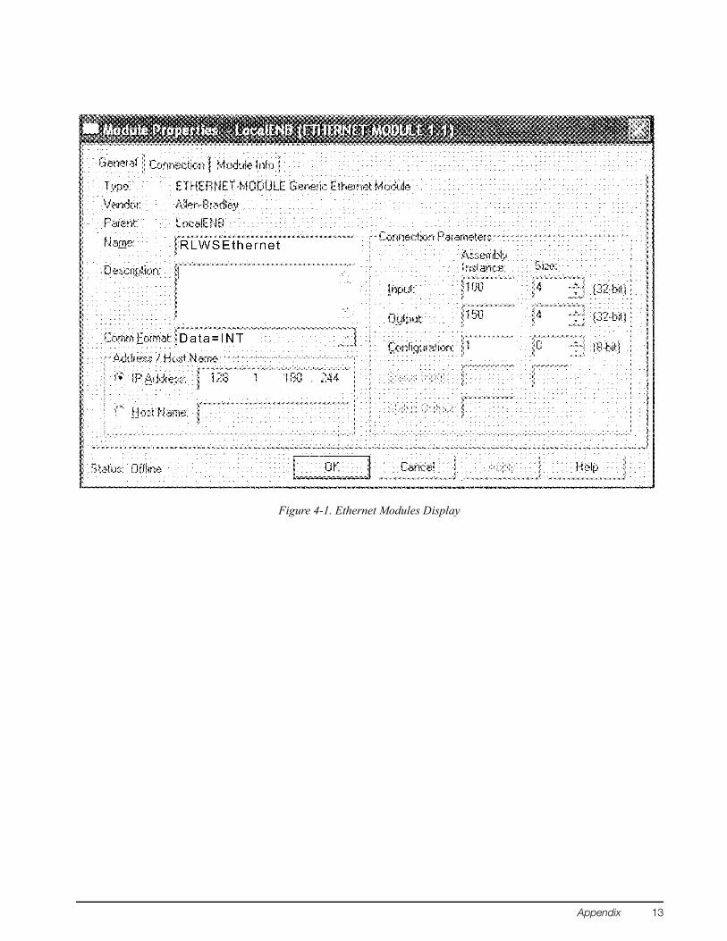
Figure 4-1. Ethernet Modules Display
Appendix 13
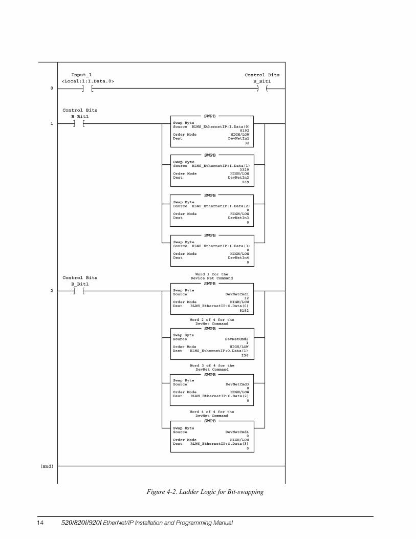
Figure 4-2. Ladder Logic for Bit-swapping
<Local:1:I.Data.0>
0
1
2
(End)
Input_1
[] ) (B_Bit1
Control Bits
[]B_Bit1
Control Bits
Swap ByteSource RLWS_EthernetIP:I.Data(0) 8192Order Mode HIGH/LOWDest DevNetIn1 32
SWPB
Swap ByteSource RLWS_EthernetIP:I.Data(1) 3329Order Mode HIGH/LOWDest DevNetIn2 269
SWPB
Swap ByteSource RLWS_EthernetIP:I.Data(2) 0Order Mode HIGH/LOWDest DevNetIn3 0
SWPB
Swap ByteSource RLWS_EthernetIP:I.Data(3) 0Order Mode HIGH/LOWDest DevNetIn4 0
SWPB
[]B_Bit1
Control Bits
Swap ByteSource DevNetCmd1 32Order Mode HIGH/LOW Dest RLWS_EthernetIP:O.Data(0) 8192
SWPB
SWPB
SWPB
SWPB
Swap ByteSource DevNetCmd2 1Order Mode HIGH/LOW Dest RLWS_EthernetIP:O.Data(1) 256
Swap ByteSource DevNetCmd3 0Order Mode HIGH/LOW Dest RLWS_EthernetIP:O.Data(2) 0
Swap ByteSource DevNetCmd4 0Order Mode HIGH/LOW Dest RLWS_EthernetIP:O.Data(3) 0
Word 1 for theDevice Net Command
Word 2 of 4 for theDevNet Command
Word 3 of 4 for theDevNet Command
Word 4 of 4 for theDevNet Command
14 520/820i/920i EtherNet/IP Installation and Programming Manual

4.2 EDS FileThe EDS file for the EtherNet/IP adapter, shown below, is included on the CD that comes with the option. The EDS file must be installed in the host device to enable communication with the indicator.
[File] DescText = "HMS AnyBus-Communicator EtherNet/IP"; CreateDate = 04-02-2003; CreateTime = 14:40:00; ModDate = 07-22-2003; ModTime = 10:45:00; Revision = 1.2;
[Device] VendCode = 90; VendName = "HMS Networks"; ProdType = 12; ProdTypeStr = "Communication Adapter"; ProdCode = 1; MajRev = 1; MinRev = 17; ProdName = "Anybus-C EtherNet/IP"; Catalog = "Anybus-C EtherNet/IP";
[Device Classification] Class1 = EtherNetIP;
[Params] Param1 = 0, $ first field shall equal 0 ,, $ path size,path 0x0000, $ descriptor 0xC7, $ data type : 16-bit Unsigned Integer 2, $ data size in bytes "Output Size", $ name "", $ units "", $ help string 0, 504, 16, $ min, max, default data values 0, 0, 0, 0, $ mult, dev, base, offset scaling not used 0, 0, 0, 0, $ mult, dev, base, offset link not used 0; $ decimal places not used
Param2 = 0, $ first field shall equal 0 ,, $ path size,path 0x0000, $ descriptor 0xC7, $ data type : 16-bit Unsigned Integer 2, $ data size in bytes "Input Size", $ name "", $ units "", $ help string 0, 504, 16, $ min, max, default data values 0, 0, 0, 0, $ mult, dev, base, offset scaling not used 0, 0, 0, 0, $ mult, dev, base, offset link not used 0; $ decimal places not used
[Connection Manager] Connection1 = 0x04010002, $ trigger & transport $ 0-15 = supported transport classes (class 1) $ 16 = cyclic (1 = supported)
Appendix 15

$ 17 = change of state (0 = not supported) $ 18 = on demand (0 = not supported) $ 19-23 = reserved (must be zero) $ 24-27 = exclusive owner $ 28-30 = reserved (must be zero) $ 31 = client 0 (don't care for classes 0 and 1) 0x44240405, $ point/multicast & priority & realtime format $ 0 = O=>T fixed (1 = supported) $ 1 = O=>T variable (0 = not supported) $ 2 = T=>O fixed (1 = supported) $ 3 = T=>O variable (0 = not supported) $ 4-7 = reserved (must be zero) $ 8-10 = O=>T header (4 byte run/idle) $ 11 = reserved (must be zero) $ 12-14 = T=>O header $ 15 = reserved (must be zero) $ 16-19 = O=>T point-to-point $ 20-23 = T=>O multicast $ 24-27 = O=>T scheduled $ 28-31 = T=>O scheduled ,Param1,, $ O=>T RPI,Size,Format ,Param2,, $ T=>O RPI,Size,Format ,, $ config part 1 (dynamic assemblies) ,, $ config part 2 (module configuration) "ABC-EIP IO Connection", $ connection name "", $ Help string "20 04 24 01 2C 96 2C 64"; $ exclusive output path
4.3 EtherNet/IP Interface SpecificationsPower RequirementsBus Adapter Card with EtherNet/IP Module, DC Power:
Supply voltage: 6 VDC, supplied by 520/920i busTypical current draw: 270 mAPower consumption: 1.62 W
Indicators, Typical AC Load:520 Power (TRMS): 3.51 W
Current (TRMS): 33.7 mA
820i Power (TRMS): 2.18 WCurrent (TRMS): 28.9 mA
920i Power (TRMS): 2.18 WCurrent (TRMS): 28.9 mA
Communications SpecificationsEtherNet/IP Network Communications:
Twisted-pair cabling at 10 or 100Mbps
Environmental SpecificationsTemperature: –10° to +40° C (14° to 104° F)
Conformance
The Anybus-S EtherNet/IP Interface has been tested by ODVA’s independent test lab and found to comply with the ODVA composite conformance test, revision 3.
The EtherNet/IP Interface has been found in accordance with EMC directive 89/336/EEC for European standards EN 50081-2 and EN 61000-6-2.
16 520/820i/920i EtherNet/IP Installation and Programming Manual

EtherNet/IP Interface Limited WarrantyRice Lake Weighing Systems (RLWS) warrants that all RLWS equipment and systems properly installed by a Distributor or Original Equipment Manufacturer (OEM) will operate per written specifications as confirmed by the Distributor/OEM and accepted by RLWS. All systems and components are warranted against defects in materials and workmanship for one year. RLWS warrants that the equipment sold hereunder will conform to the current written specifications authorized by RLWS. RLWS warrants the equipment against faulty workmanship and defective materials. If any equipment fails to conform to these warranties, RLWS will, at its option, repair or replace such goods returned within the warranty period subject to the following conditions:
• Upon discovery by Buyer of such nonconformity, RLWS will be given prompt written notice with a detailed explanation of the alleged deficiencies.
• Individual electronic components returned to RLWS for warranty purposes must be packaged to prevent electrostatic discharge (ESD) damage in shipment. Packaging requirements are listed in a publication, “Protecting Your Components From Static Damage in Shipment,” available from RLWS Equipment Return Department.
• Examination of such equipment by RLWS confirms that the nonconformity actually exists, and was not caused by accident, misuse, neglect, alteration, improper installation, improper repair or improper testing; RLWS shall be the sole judge of all alleged non-conformities.
• Such equipment has not been modified, altered, or changed by any person other than RLWS or its duly authorized repair agents.
• RLWS will have a reasonable time to repair or replace the defective equipment. Buyer is responsible for shipping charges both ways.
• In no event will RLWS be responsible for travel time or on-location repairs, including assembly or disassembly of equipment, nor will RLWS be liable for the cost of any repairs made by others.
THESE WARRANTIES EXCLUDE ALL OTHER WARRANTIES, EXPRESSED OR IMPLIED, INCLUDING WITHOUT LIMITATION WARRANTIES OF MERCHANTABILITY OR FITNESS FOR A PARTICULAR PURPOSE. NEITHER RLWS NOR DISTRIBUTOR WILL, IN ANY EVENT, BE LIABLE FOR INCIDENTAL OR CONSEQUENTIAL DAMAGES. RLWS AND BUYER AGREE THAT RLWS’S SOLE AND EXCLUSIVE LIABILITY HEREUNDER IS LIMITED TO REPAIR OR REPLACEMENT OF SUCH GOODS. IN ACCEPTING THIS WARRANTY, THE BUYER WAIVES ANY AND ALL OTHER CLAIMS TO WARRANTY.SHOULD THE SELLER BE OTHER THAN RLWS, THE BUYER AGREES TO LOOK ONLY TO THE SELLER FOR WARRANTY CLAIMS.NO TERMS, CONDITIONS, UNDERSTANDING, OR AGREEMENTS PURPORTING TO MODIFY THE TERMS OF THIS WARRANTY SHALL HAVE ANY LEGAL EFFECT UNLESS MADE IN WRITING AND SIGNED BY A CORPORATE OFFICER OF RLWS AND THE BUYER.
© 2008 Rice Lake Weighing Systems, Inc. Rice Lake, WI USA. All Rights Reserved.
RICE LAKE WEIGHING SYSTEMS • 230 WEST COLEMAN STREET • RICE LAKE, WISCONSIN 54868 • USA
Appendix 17