installation and servicing instructions - heating spares ltd · supplied by spares.co tel. 0161 620...
TRANSCRIPT

Supplied By www.heating spares.co Tel. 0161 620 6677
220676A.05.95COSHH
Installation and Servicing InstructionsTo b e l e f t w i t h t h e u s e r
30GC No. 41 319 14
Hepworth Heating Ltd.,Nottingham Road, Belper, Derbyshire. DE56 1JT
General/Sales enquiries:Tel: (01773) 824141 Fax: (01773) 820569One Contact Total Service
Customer Services:
Tel: (01773) 828100
Fax: (01773) 828070
4746
Fanned Flue Sealed System Boi ler
This is a Cat I2H
Appliance BS 6332BS 5258
Reference in these instructions to British Standards andStatutory Regulations/Requirements apply only to the UnitedKingdom.
For Ireland the rules in force must be used.

Supplied By www.heating spares.co Tel. 0161 620 6677
2220676A
1 General
OVERALL DIMENSIONS Diagram 1.1
The instructions consist of two parts, Installation andServicing and Instructions for Use. They are theproperty of the user and must be handed to them oncompletion of the installation.
1.1 Important Notices
This boiler is for use on natural gas (G20) as distributedin the United Kingdom and Ireland and cannot be usedon any other gas.
Wherever possible, all materials, appliances andcomponents to be used shall comply with therequirements of applicable British Standards.
Where no British Standard exists, materials andequipment should be fit for their purpose and of suitablequality and workmanship.
This boiler is not suitable for use out of doors.
THIS BOILER IS FOR USE ONLY IN A SEALEDWATER SYSTEM.
1.2 Sheet Metal Parts
WARNING. When installing or servicing the boiler careshould be taken when handling sheet metal parts to avoidany possibility of personal injury.
1.3 Statutory Requirements
The installation of the boiler MUST be carried out by acompetent person in accordance with the relevantrequirements of the current issue of:
The manufacturer’s instructions supplied.
The Gas Safety (Installation and Use) Regulations, TheBuilding Regulations, The Building Standards (Scotland)Regulations (applicable in Scotland) Local WaterCompany Bye-laws, The Health and Safety at Work Act,The Electricity at Work Regulations, Control ofSubstances Hazardous to Health, The Electricity at WorkRegulations and any applicable local regulations.
Detailed recommendations are contained in the currentissue of the following British Standards and Codes ofPractice,
BS4814, BS5440 Part 1 and 2, BS5449, BS5546,BS6700, BS6798, BS6891, BS7074 Part 1 and 2,BS7478, BS7593, BS7671.
Manufacturer’s instructions must not be taken asoverriding statutory requirements.
1.4 BSI Certification
The boiler is certificated to the current issue of BS6332Part 1, invoking the current issue of BS5258 Part 1 forperformance and safety. It is, therefore, important thatno alteration is made to the boiler, without permission, inwriting, from Hepworth Heating Ltd.
3130
108
450
161
783
*
174
321
101
783
346
66
2.5
25
SAFETYVALVEDISCHARGE
All dimensions in millimetres
KEY:22mm COMPRESSIONCENTRAL HEATING
Rc1/2(1/2 in. BSPT)GAS CONNECTION
STD FLUE TERMINAL = 63LONG FLUE TERMINAL = 61*
*

Supplied By www.heating spares.co Tel. 0161 620 6677
3 220676A
1 General
30
DATA TABLE 1
29.86kg
(65.83lb)
LIFTING
WEIGHT
Rc 1/2 (1/
2 in. BSPT)
GASCONNECTION
WATERCONNECTION
22mm copper,
return at right, flow at left
135W, internal fuse F1A.ELECTRICITYRATING
0.62 litre
(0.136 gal)WATERCONTENT
TOTAL
WEIGHT
240V~50Hz fused 3AELECTRICITYSUPPLY
DATA LABEL On the inner case front
44.36kg
(97.80lb)
Any alteration that is not approved by Hepworth HeatingLtd., could invalidate the BSI Certification of the boiler,the warranty and could also infringe the current issue ofthe Statutory Requirements.
CE Mark
The CE mark on this appliance shows compliance withDirective 90/396/EEC on the approximation of the Lawsof the Member States relating to appliances burninggaseous fuels.
The CE mark on this appliance shows compliance withDirective 73/23/EEC on the harmonization of the Lawsof the Member States relating to electrical equipmentdesigned for use within certain voltage limits.
1.5 Range Rating
The boiler is range rated and is factory preset tomaximum, but may be adjusted to suit individual systemrequirements, refer to Range Rating, Table 2.
1.6 Equipment
The boiler is supplied with an integral expansion vessel,circulating pump, safety valve, pressure gauge, lowwater pressure warning light, automatic bypass valve,gas cock and valved water connections (with drainpoints).
Data Label
The data label is positioned on the inner case cover.
Appliance Data refer to Table 1
Range Rating - Table 2.
1.7 Gas Supply
The gas installation must be in accordance with thecurrent issue of BS6891.
The supply from the governed meter must be of adequatesize to provide a steady inlet working pressure of20mbar (8in wg) at the boiler.
On completion, test the gas installation for soundnessusing the pressure drop method and leak detection fluid.Purge in accordance with the current issue of BS6891.
1.8 Electrical Supply
WARNING. This boiler must be earthed.
All system components and wiring shall be of theapproved type and comply with and be connected inaccordance with the requirements of current issue ofBS7671 and any applicable local regulations.
Connection of the boiler and system controls to themains supply must be through a common isolator andmust be fused 3A maximum.
INJECTORSIZE
2.8mm
RANGE RATINGNOMINAL Btu/hHEATINPUT kW
NOMINAL Btu/hHEATOUTPUT kW
BURNER m barSETTINGPRESSURE in.w.g
APPROX m3hGASRATE ft3h
min mid max
25,300 31,250 37,080
7.5 9.2 10.8
5.3 8.9 12.4
2.1 3.6 5.0
0.7 0.9 1.0
25.1 30.9 36.6
20,000 25,000 30,000
5.9 7.3 8.8
TABLE 2. 30
The method of connection should be, preferably, by afused double pole isolating switch, provided it has aminimum contact separation of 3mm on both poles.This switch should be readily accessible and preferablyadjacent to the appliance. It should supply the applianceonly and be easily identifiable as so doing.
Alternatively an unswitched shuttered socket outlet and3A fused 3 pin plug both to the current issue of BS1363may be used provided that they are not used in a roomcontaining a bath or shower.
Wiring to the boiler must be to the current to the ofBS6500 Table 16.

Supplied By www.heating spares.co Tel. 0161 620 6677
4220676A
2 Water System
Diagram 2.2WATER SYSTEMDIAGRAMATIC LAYOUT
2.1 General Notes
The installation of the boiler must comply with therequirements of the current issue of BS6798.
2.2 Safety Valve
The safety valve, preset at 3bar, is an integral part of theboiler and cannot be adjusted.
2.3 Pressure gauge
A pressure gauge is incorporated into the boiler toindicate the system pressure.
2.4 Circulating Pump
The circulating pump is integral with the boiler.
The remaining conveying capacity of the pump is shownin diagram 2.1.
2.5 Expansion Vessel
The boiler has an integral expansion vessel with acapacity of 5Litres (1.10 gallons), with a charge pressureof 0.75bar.
The maximum heating system water content using thefitted expansion vessel ranges from 73litres with a coldfill pressure of 0.7bar, to 60litres with a cold fill pressureof 1.05bar. If, due to a high static head, the cold fillpressure is higher, then the expansion vessel pre-fillpressure must be increased, and the maximum systemvolume decreased, see the current issue of BS7074Part 1.
Further information can be obtained from the British GasPublication “British Gas Specification for Domestic WetCentral Heating Systems” and the current issue ofBS4814, BS5449 and BS7074 Part 1 and 2.
2.6 Flow Rate
A valve must be incorporated in the main flow or returnof the system, valve “A” shown in the flow diagram 2.2.This valve must be lockable and be positioned so thatinadvertent closure or unauthorised interference is notpossible. The design differential is 11oC (20oF) with theboiler thermostat set at “MAX” which is about 82oC(180oF). The pump adjuster should always be left atmaximum (3).
2.7 Bypass
An automatic bypass valve is incorporated in the boilerpipework it is preset and must not be adjusted.
Diagram 2.1
WATER FLOW RATEAt 110C (200F) differential
UNIT
litre/min. 11.5
gal/min. 2.5
MODEL 30
REMAINING CONVEYINGCAPACITY OF PUMP
3131
3 LITRES MAKE-UP BOTTLE(if required)
NON-RETURNVALVE
AUTOAIRVENT
'A'
ADDITIONALEXPANSIONVESSEL(if required)
DRAINCOCK
BOILER
RETURN
FLOW CONTROLVALVE
FILLINGPOINT
HE
AT
ING
CIR
CU
IT
12
10
8
6
4
2
0
3.0
2.4
1.8
1.2
00 5 10 15 20 25 30
Flow rate (litres/minute)
Ava
ilabl
e pu
mp
head
(F
t)0.6
3.60 1.1 2.2 3.3 4.4 5.5 6.6
Flow rate (gallons/minute)
Ava
ilabl
e pu
mp
head
(m
)
Nominal flow rate for 110C differential
3131
/A

Supplied By www.heating spares.co Tel. 0161 620 6677
5 220676A
2 Water Systems
Diagram 2.3FILLING SEALEDWATER SYSTEMS
2.8 Water Make Up
Provision should be made for replacing water lost fromthe system using a make up bottle mounted in a positionhigher than the top point of the system, connectedthrough a non-return valve to the return side of theheating circuit, see diagram 2.2.
Alternatively, provision for make up can be made usinga filling loop.
2.9 Filling Sealed Water Systems
Provision for filling the system at a low level must bemade.
Three methods of filling are shown in diagram 2.3.There must be no permanent connection to the mainswater supply, even through a non-return valve.
2.10 Corrosion Inhibitor
Attention is drawn to the current issue of BS5449 andBS7593 on the use of inhibitors in central heatingsystems.
If an inhibitor is to be used in the system, contact amanufacturer for their recommendations.
2.11 Existing Systems
When fitting the boiler into an existing system, specialcare should be taken to drain the entire system, includingradiators, then thoroughly cleaning out before fitting theboiler whether or not adding an inhibitor.
2.12 Draining Tap
A draining tap must be provided at the lowest points ofthe system, which will allow the entire system to bedrained. An additional draining tap MUST be fittedclose to the boiler.
Draining taps must be to the current issue of BS2879.
The flow and return isolating valves on the boiler arefitted with drain points for heat exchanger draining.
2.13 Domestic Hot Water System
General
The domestic hot water service must be in accordancewith the current issue of BS5546, refer also to thecurrent issue of BS6700.
2.14 Domestic Hot Water Cylinder
SINGLE FEED INDIRECT CYLINDERS ARE NOTSUITABLE AND SHOULD NOT BE USED.
The domestic hot water cylinder must be of the indirectcoil type. It must be suitable for a working at a gaugepressure of 0.35bar above the safety valve setting.
2.15 Domestic Hot Water System -Unvented
Where a storage system will not have a vent toatmosphere the installation must comply with BuildingRegulations and local Water Company bye-laws, seealso the current issue of BS6700.
If fitting into an existing system the local authority mustbe informed.
2819
METHOD 1
METHOD 2
METHOD 3
SUPPLY STOPVALVESUPPLY
PIPE
HOSEUNIONS
SERVICINGVALVE
TEMPORARYHOSE
HEATINGSYSTEM
HEATINGSYSTEMTEMPORARY
HOSE
HOSEUNIONS
SERVICINGVALVE
SUPPLYPIPE
SUPPLY STOPVALVE
DOUBLE CHECKVALVE ASSEMBLY
HEATINGSYSTEMSERVICING
VALVE
SUPPLYSTOP VALVE
SUPPLYPIPE
HOSEUNIONS DOUBLE CHECK
VALVE ASSEMBLY
OVERFLOWCISTERN
COMBINEDCHECK VALVEAND VACUUMBREAKER
PRESSUREREDUCINGVALVE

Supplied By www.heating spares.co Tel. 0161 620 6677
6220676A
3 Boiler Location
TABLE 3. COMPARTMENT AIR VENTS
VENTILATIONREQUIREMENTS
HIGH LEVEL LOW LEVEL
VENT AREA VENT AREA
cm2 in2 cm2 in2
VENTILATIONFROMROOMOR SPACE
MODEL
30
VENTILATIONFROMOUTSIDE
98 14 98 14
49 7 49 730
3.1 General
The boiler may be installed in any room althoughparticular attention is drawn to the requirements of thecurrent issue of BS7671 with respect to the installationof a boiler in a room containing a bath or shower.
Any electrical switch or boiler control using mainselectricity should be so situated that it cannot be touchedby a person using the bath or shower.
The electrical provisions of the Building Standards(Scotland) Regulations are applicable to suchinstallations in Scotland.
The boiler must be mounted on a flat wall which issufficiently robust to take its complete weight, seeAppliance Data, Table 1.
The boiler may be fitted to a wall made of combustiblematerial. See diagram 3.1.
3.2 Boiler Clearances
The boiler should be positioned so that at least theminimum operational and servicing clearances areprovided, see diagram 3.1.
3.3 Timber Frame Buildings
If the boiler is to be installed in a timber frame building,it should be fitted in accordance with the British GasPublication “Guide for Gas Installation in TimberFramed Housing” reference DM2. If in doubt, seekadvice from the local gas undertaking or HepworthHeating Ltd.
3.4 Room Vent
The boiler is room sealed, so when installed in a room orspace, a permanent air vent is not required.
3.5 Cupboard or Compartment Vent
Where the boiler is fitted in a cupboard or compartment,permanent high and low level ventilation must beprovided.
The vent areas required are given in Table 3.
Where the installation of the boiler will be in an unusuallocation, special procedures are necessary, refer to thecurrent issue of BS6798 for guidance.
Make sure that the cupboard or compartment air ventsare positioned to be clear of obstructions at all times.
A compartment used to enclose the boiler must bedesigned and constructed specifically for this purpose.
An existing cupboard or compartment modified for thepurpose may be used, refer to the current issue ofBS6798 for guidance.
The doorway opening should be of sufficient size toallow easy removal of the boiler.
❋ WHERE EXTERNAL ACCESS TO
THE FLUE IS NOT PRACTICAL THENCLEARANCE MUST BE ADEQUATE TOPERMIT INSTALLATION OF THE FLUE
MINIMUM CLEARANCES FROM WALLS,CEILING, FLOOR, CUPBOARD, WORK TOPSAND INFLAMMABLE MATERIALS Diagram 3.1
3133
5
5
5
5
186
*800
150
*5
*5
Supplied By www.heating spares.co Tel. 0161 620 6677
7 220676A
4 Flue
SIDE FLUE Diagram 4.2
REAR FLUE Diagram 4.1
STANDARD FLUE TERMINAL ILLUSTRATED
STANDARD FLUE TERMINAL ILLUSTRATED
3134
3135
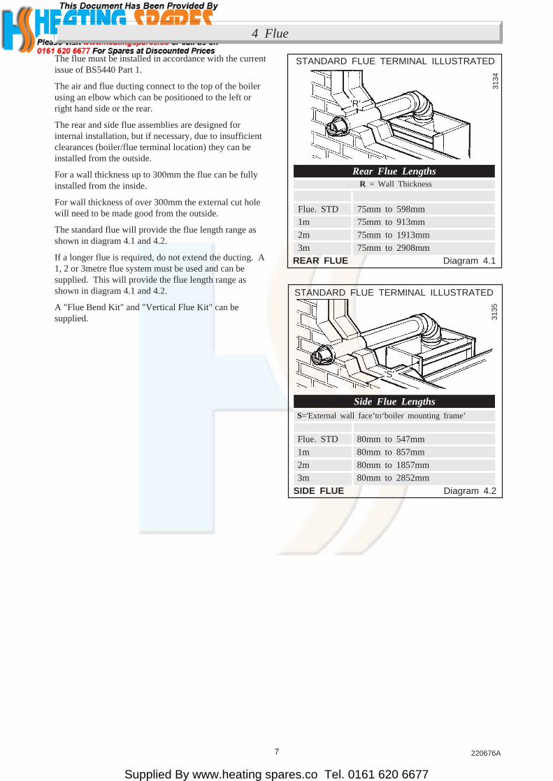
The flue must be installed in accordance with the currentissue of BS5440 Part 1.
The air and flue ducting connect to the top of the boilerusing an elbow which can be positioned to the left orright hand side or the rear.
The rear and side flue assemblies are designed forinternal installation, but if necessary, due to insufficientclearances (boiler/flue terminal location) they can beinstalled from the outside.
For a wall thickness up to 300mm the flue can be fullyinstalled from the inside.
For wall thickness of over 300mm the external cut holewill need to be made good from the outside.
The standard flue will provide the flue length range asshown in diagram 4.1 and 4.2.
If a longer flue is required, do not extend the ducting. A1, 2 or 3metre flue system must be used and can besupplied. This will provide the flue length range asshown in diagram 4.1 and 4.2.
A "Flue Bend Kit" and "Vertical Flue Kit" can besupplied.
Rear Flue Lengths
S='External wall face’to‘boiler mounting frame’
Side Flue Lengths
Flue. STD 80mm to 547mm1m 80mm to 857mm2m 80mm to 1857mm3m 80mm to 2852mm
Flue. STD 75mm to 598mm1m 75mm to 913mm2m 75mm to 1913mm3m 75mm to 2908mm
R = Wall Thickness
'S'
'R'
Supplied By www.heating spares.co Tel. 0161 620 6677
8220676A
A
A
FG E
A
G
G
G
B,C B,C
F FK
K
K
C
G
L L
UNDER CAR PORT etc.
H,I
JD
FK
4 Flue
4.1 Terminal Position
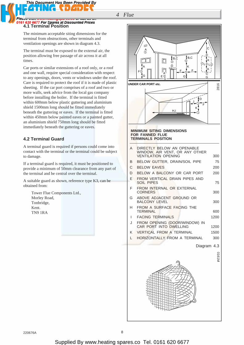
The minimum acceptable siting dimensions for theterminal from obstructions, other terminals andventilation openings are shown in diagram 4.3.
The terminal must be exposed to the external air, theposition allowing free passage of air across it at alltimes.
Car ports or similar extensions of a roof only, or a roofand one wall, require special consideration with respectto any openings, doors, vents or windows under the roof.Care is required to protect the roof if it is made of plasticsheeting. If the car port comprises of a roof and two ormore walls, seek advice from the local gas companybefore installing the boiler. If the terminal is fittedwithin 600mm below plastic guttering and aluminiumshield 1500mm long should be fitted immediatelybeneath the guttering or eaves. If the terminal is fittedwithin 450mm below painted eaves or a painted gutter,an aluminium shield 750mm long should be fittedimmediately beneath the guttering or eaves.
4.2 Terminal Guard
A terminal guard is required if persons could come intocontact with the terminal or the terminal could be subjectto damage.
If a terminal guard is required, it must be positioned toprovide a minimum of 50mm clearance from any part ofthe terminal and be central over the terminal.
A suitable guard as shown, reference type K3, can beobtained from:
Tower Flue Components Ltd.,Morley Road,Tonbridge,Kent.TN9 1RA
2816
A DIRECTLY BELOW AN OPENABLEWINDOW, AIR VENT, OR ANY OTHERVENTILATION OPENING 300
B BELOW GUTTER, DRAIN/SOIL PIPE 75
C BELOW EAVES 200
D BELOW A BALCONY OR CAR PORT 200
E FROM VERTICAL DRAIN PIPES ANDSOIL PIPES 75
F FROM INTERNAL OR EXTERNALCORNERS 300
G ABOVE ADJACENT GROUND ORBALCONY LEVEL 300
H FROM A SURFACE FACING THETERMINAL 600
I FACING TERMINALS 1200
J FROM OPENING (DOOR/WINDOW) INCAR PORT INTO DWELLING 1200
K VERTICAL FROM A TERMINAL 1500
L HORIZONTALLY FROM A TERMINAL 300
MINIMUM SITING DIMENSIONS FOR FANNED FLUE TERMINALS POSITION
Diagram 4.3
0161M

Supplied By www.heating spares.co Tel. 0161 620 6677
9 220676A
5 Preparation
OUTER CASE Diagram 5.1
Diagram 5.3GAS SERVICE COCK / WATER ISOLATING VALVES
INNER CASE COVER Diagram 5.2
5.1 Unpacking
Remove the top carton from the boiler.
To remove the outer case, slide the information plate upto access and remove the single securing screw, seediagram 5.1, unhook the case at the top and lift it off.
Remove the cover of the inner case, secured with fourscrews, see diagram 5.2.
Disconnect the gas service cock union and the frontunions of the isolation valves, see diagram 5.3.
Slacken but do not remove the retaining strap screws ofthe gas service cock and the isolating valves.
3137
3138
3139
OUTER CASE SECURING SCREW
INFORMATIONPLATE
INNER CASECOVER
SECURINGSCREW (4)
RETAININGSTRAP
GAS SERVICECOCK UNION
FLOWWATERISOLATINGVALVE UNION
RETAININGSTRAP
RETAININGSTRAP
RETURNWATERISOLATINGVALVEUNION

Supplied By www.heating spares.co Tel. 0161 620 6677
10220676A
SIDE FLUE Diagram 6.2BOILER FIXING POINTS Diagram 6.1
Remove the two boiler securing screws, see diagram 5.4then separate the boiler from the mounting frame, bypulling the location studs/clips apart then unhook it atthe top.
6.2 Marking
The boiler mounting frame is the same width as theboiler but the flue connection protrudes above. Place theboiler mounting frame on the wall in the requiredposition, maintaining minimum clearances,see diagram 3.1.
3140
BOILERSECURING SCREW (2)
LOCATIONSTUD(S) and CLIP(S)
FLUETEMPLATE
BOILERMOUNTING FRAME
FIXING POINTS480
629
149
78 FLUECENTRE LINE
115 Diameter
Top ofBoiler
MINIMUMCLEARANCE
300
173 173
115 Dia.FLUECENTRELINES
CORNER(LEFT FLUE)
CORNER(RIGHT FLUE)
3142
3143
BOILERMOUNTING FRAME
5 Preparation
6.1
With due regard to boiler location, clearances andhaving determined the flue application, length andterminal position carry on as follows:
BOILERMOUNTING FRAME Diagram 5.4
6 Installing the Flue

Supplied By www.heating spares.co Tel. 0161 620 6677
11 220676A
6 Installing the Flue
WALL SLEEVE Diagram 6.3
Diagram 6.4BOILERMOUNTING FRAME
Make sure that the isolation valves are at the bottomfacing forward and that the frame top is horizontal, thenmark the four fixing points through the holes in the twohorizontal straps, do not drill the holes, see diagram 6.4.
Position the flue template on the wall, the arrow pointson the centres of the two upper fixing points previouslymarked, see diagram 6.1 which also gives dimensions.
For a rear flue, mark the rear flue position as required,centre or diameter.
For a side flue, mark the horizontal flue centre line at thesides of the template. Extend the flue centre linehorizontally left or right to the internal corner where theflue is required to exit to the outside. Mark the positionof the circular hole, on the flue exit wall, using thedimensions given in diagram 6.2.
From the flue position marks, check that the flueterminal will be in a suitable position, see diagram 4.3.
6.3 Flue Hole Cutting
Cut a horizontal hole in the wall, ensuring that there isno downward slope toward the boiler position, using,preferably, a core drill, to the diameter shown in diagram6.1 and 6.2.
6.4 Wall Sleeve
Take the wall sleeve from the pack. If the wall thickness“Q” is less than 300mm, cut the wall sleeve to therequired length, see diagram 6.3. If the wall thickness“Q” is greater than 300mm the sleeve must be fittedflush with the outside wall face.
Place the sleeve into the hole.
Make good around the wall sleeve at both internal andexternal wall faces, through the wall sleeve if internalaccess only is available.
For a wall thickness of over 300mm the external wallface will need to be made good from the outside.
6.5 Boiler Mounting Frame - Fixing
Position the flue template over the flue hole and checkthe position of the wall fixing points. Mark the positionof the fixing holes again, if required, see diagram 6.1.
Drill the four holes and insert wall plugs to suitNo10x50mm screws.
Secure the boiler mounting frame to the wall usingNo10x50mm screws, see diagram 6.4.
Note: Remove the clear plastic protective film from thesides of the boiler mounting frame.
3145
FIXINGPOINTS
BOILER MOUNTINGFRAME
Q300mmMAX. LENGTH
WALLSLEEVE
3144
Q

Supplied By www.heating spares.co Tel. 0161 620 6677
12220676A
6 Installing the Flue
6.6 Flue Preparation
Rear Flue
Mark and cut the air duct terminal assembly, see diagram6.5 and the flue duct, see diagram 6.6 to the lengthsrequired, cutting square and removing any burrs.
Refer to diagram 6.9, mark through the holes in the flueelbow assembly and drill the flue duct as shown.
Side Flue
Mark and cut the air duct terminal assembly, see diagram6.7 and the flue duct, see diagram 6.8 to the lengthsrequired, cutting square and removing any burrs.
Refer to diagram 6.9, mark through the holes in the flueelbow assembly and drill the flue duct as shown.
6.6 Flue Assembly
Note. At this point if side or front access is restricted,continue at “External Flue Assembly”.
Internal Flue Assembly
Locate the flue duct into the flue elbow assembly andsecure with the screws provided, see diagram 6.9.
Fully locate the flue elbow and flue duct assembly intothe air duct/terminal assembly as shown, ensuringcorrect terminal alignment of the “TOP”, see diagram6.10.
Mark the position of the air duct terminal assemblysecuring holes and drill two 3mm diameter holes throughthe air duct/terminal assembly.
Secure the air duct/terminal assembly to the flue elbowand flue duct assembly with the two self tapping screwssupplied in the loose items pack and then seal with thetape provided.
Diagram 6.7
SIDE FLUE - FLUE DUCT Diagram 6.8
SIDE FLUE - AIR DUCT /TERMINAL ASSEMBLY
Diagram 6.5REAR FLUE - AIR DUCT /TERMINAL ASSEMBLY
REAR FLUE - FLUE DUCT Diagram 6.6
3147
3146
STANDARD FLUE TERMINAL ILLUSTRATED
FLUEDUCT
'R' + 107
'R'
3148
STANDARDFLUETERMINAL
AIR DUCT/TERMINALASSEMBLY
'S' + 148
'S'
STANDARD FLUE TERMINAL ILLUSTRATED
3149
'S' + 163
FLUEDUCT
'S'
'R' + 92
STANDARDFLUETERMINAL
'R'
AIR DUCT/TERMINALASSEMBLY
1m,2m,3m LONG FLUE TERMINAL
1m,2m,3m LONG FLUE TERMINAL

Supplied By www.heating spares.co Tel. 0161 620 6677
13 220676A
6 Installing the Flue
Diagram 6.10FLUE ASSEMBLY
Diagram 6.9FLUE ELBOW /DUCT ASSEMBLY
Fix the self adhesive seal to the air duct,see diagram 6.11.
Place the flue assembly into the flue hole. Make surethat the flue terminal is correctly positioned andprojecting the correct distance from the outside wallface, see diagram 6.11.
Note: The foam seal is a tight fit in the wall sleeve, soeither the wall sleeve will need to be rigidly fixed in thewall, that is, the cement has fully set or it can be heldfrom the other side whilst inserting the flue assembly.
External Flue Installation
Locate the air duct/terminal assembly into the flue elbowassembly as shown in diagram 6.10, ensuring correctterminal alignment of the “TOP”.
Mark the position of the air duct terminal assemblysecuring holes and drill two 3mm diameter holes throughthe air duct/terminal.
Fix the self adhesive seal to the air duct,see diagram 6.11.
From outside, place the air duct/terminal assembly andflue duct into the flue hole. Make sure that the flueterminal is correctly positioned and projecting the correctdistance from the outside wall face, see diagram 6.11.
3151
3150
FLUE DUCT
SECURINGSCREW (2)FLUE ELBOW
ASSEMBLY
AIR DUCT/TERMINAL& FLUE DUCTASSEMBLY
FLUEELBOWASSEMBLY
Note: The foam seal is a tight fit in the wall sleeve, soeither the wall sleeve will need to be rigidly fixed in thewall, that is, the cement has fully set or it can be heldfrom the other side whilst inserting the flue assembly.
SCREW (2)3mm
DRILL SIZE

Supplied By www.heating spares.co Tel. 0161 620 6677
14220676A
6 Installing the flue
Locate the flue duct into the flue elbow assembly andsecure with the screws provided.
Secure the air duct terminal to the flue elbow with thetwo self tapping screws supplied in the loose items pack,making sure that the flue duct is correctly located intothe terminal, see diagram 6.11, then seal with the tapeprovided.
FLUE TERMINAL Diagram 6.11
7 Gas, Water and Electrical Connections
3153
7.1 Gas Connection
The gas supply can be connected from below or throughthe wall at the rear of the boiler, see diagram 7.1 forposition.
Refer also to Section 1.7.
Make the gas connection to the gas service cock.
Slacken or remove the securing strap, whilst making theconnection. Do not subject the gas service cock to heat.
7.2 Water Connections
Provision is made for the flow and return pipes to beconnected from above, if required, passing down eitherside of the boiler, see diagram 7.2 for clearances.
Note: Take care that any pipework connected fromabove within the boiler mounting frame will clear theexpansion vessel.
Clean out the heating system before connecting theboiler.
Make the connections to the heating system by way ofthe isolating valves, see diagram 7.1.
Slacken or remove the securing straps whilst making theconnections. Do not subject the valves to heat.
Make sure that the drain points on the valves arepositioned toward the front of the boiler, also that thedrain and operating screw heads are accessible.
7.3 Safety Valve Discharge
WARNING. It must not discharge above an entrance orwindow or any type of public access area.
A discharge pipe is supplied loose with the boiler, whichwhen fitted to the safety valve, will terminate below theboiler at the notch, see diagram 7.1.
WALL SLEEVESTD FLUE TERMINAL = 63LONG FLUE TERMINAL = 61
**
FLUETERMINAL
FLUEDUCT
Outside Wall Face
3152
'NOTCH' MARKING POSITION OFSAFETY VALVE DISCHARGE
30
66
272723
33346
GASCONNECTION
WATERCONNECTION
SLOT (CLOSED) DRAINPOINT
SLOT(CLOSED)
GAS SERIVCE COCK WATER ISOLATIONVALVES
BOILER CONNECTIONS Diagram 7.1
SECURING STRAPS
SEAL

Supplied By www.heating spares.co Tel. 0161 620 6677
15 220676A
7 Gas, Water and Electrical Connections
Diagram 7.2
ELECTRICAL PLUG Diagram 7.3
UPWARD ROUTINGOF PIPEWORK
This must be extended, using not less than 15mm odpipe, to discharge, in a visible position, outside thebuilding, facing downward, preferably over a drain.The pipe must have a continuous fall and be routed to aposition such that any discharge of water, possiblyboiling water, or steam cannot create a hazard to personsor damage to property or external electrical componentsor wiring.
Note. To make future servicing easier it is advisable touse a compression type fitting when extending thedischarge pipe.
7.4 Electrical Connections
WARNING. The boiler must be earthed.
Take the electrical connector from the loose items packand remove the two screws and cover, see diagram 7.3.
Using cable to the current issue of BS6500 Table 16 of asuitable length connect the mains supply cable to theappropriate terminals of the connector, see diagram 7.3.
Standard colours are, Brown - Live (L); Blue -Neutral (N); Green/Yellow - Earth (E) or ( ).
The mains cable outer insulation must not be cut backexternal to the connector, see diagram 7.3.
Make the earth conductor of a greater length than thecurrent carrying conductors so that if the cable is strainedthe earth conductor would be the last to becomedisconnected.
It is essential that the polarity is correct.
After completing the connections secure the cable withthe connector’s cover using the two screws previouslyremoved, make sure that no basic insulated wire isaccessible outside of the connector, see diagram 7.3.
Clip the electrical connector into position on the boilermounting frame and secure the mains cable with thecable clamp immediately behind the connector.
If necessary also secure the cables to the wall usingsuitable cable clips.
Keep cables away from hot surfaces.
Carry out preliminary electrical system checks, using asuitable Multimeter, that is, earth continuity, polarity,short circuit and resistance to earth.
7.5 Heating System Controls
It is recommended that the system is controlled by a timeswitch and room thermostat, proprietary control systemor by thermostatic radiator valves, refer to diagram 12.5.Refer to the current issue of BS7478 for guidance on theuse of thermostatic radiator valves.
GAS CONNECTIONWATER CONNECTION
Note: Keep any pipeworkclear of shaded area.
3154
3156
COVER
CABLE CLAMP
MAINSCABLE
CONNECTOR
N
L
E
EXPANSIONVESSELPOSITION
52
320
4620
Supplied By www.heating spares.co Tel. 0161 620 6677
16220676A
8 Boiler and Flue Fixing
FASCIA / SAFETY VALVE Diagram 8.2
8.1 Mounting the Boiler
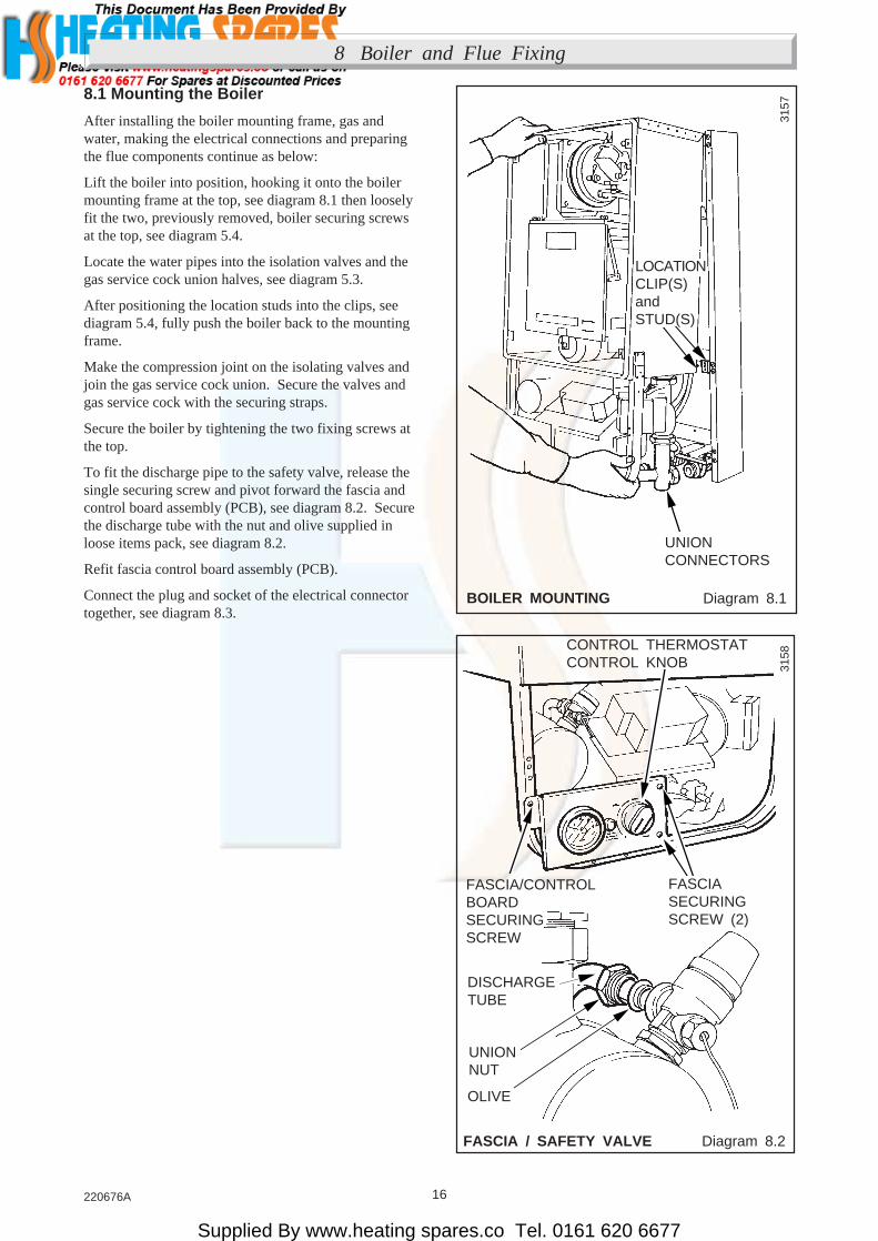
After installing the boiler mounting frame, gas andwater, making the electrical connections and preparingthe flue components continue as below:
Lift the boiler into position, hooking it onto the boilermounting frame at the top, see diagram 8.1 then looselyfit the two, previously removed, boiler securing screwsat the top, see diagram 5.4.
Locate the water pipes into the isolation valves and thegas service cock union halves, see diagram 5.3.
After positioning the location studs into the clips, seediagram 5.4, fully push the boiler back to the mountingframe.
Make the compression joint on the isolating valves andjoin the gas service cock union. Secure the valves andgas service cock with the securing straps.
Secure the boiler by tightening the two fixing screws atthe top.
To fit the discharge pipe to the safety valve, release thesingle securing screw and pivot forward the fascia andcontrol board assembly (PCB), see diagram 8.2. Securethe discharge tube with the nut and olive supplied inloose items pack, see diagram 8.2.
Refit fascia control board assembly (PCB).
Connect the plug and socket of the electrical connectortogether, see diagram 8.3.
3157
3158
UNIONCONNECTORS
LOCATIONCLIP(S)andSTUD(S)
CONTROL THERMOSTATCONTROL KNOB
FASCIASECURINGSCREW (2)
FASCIA/CONTROLBOARDSECURINGSCREW
DISCHARGETUBE
OLIVE
UNIONNUT
BOILER MOUNTING Diagram 8.1

Supplied By www.heating spares.co Tel. 0161 620 6677
17 220676A
8 Boiler and Flue Fixing
8.2 Flue Assembly to Boiler - Connection
NOTE. The fan could be fitted with transit clips, seediagram 8.6, which will need removing.
Slacken but do not remove the fan securing screws andflue hood wing nuts, see diagram 8.4.
Secure the flue assembly to the spigot on top of theboiler, see diagram 8.5.
Tighten the fan securing screws and flue hood wing nutspreviously slackened, see diagram 8.4.
Diagram 8.3
FLUEHOOD / FAN Diagram 8.4
ELECTRICALCONNECTOR
3159
3160
CABLECLAMP
ELECTRICALCONNECTOR
MAINS CABLE
FLUEHOODSECURINGANGLE WING NUT
FANSECURINGSCREW (2)
Diagram 8.5FLUE ASSEMBLYCONNECTION
3161
SECURINGSCREW (2)
FLUE DUCT ASSEMBLYand FLUE ELBOWFLUE
SPIGOT
TRANSIT CLIPS Diagram 8.6
REARFRONT
4856

Supplied By www.heating spares.co Tel. 0161 620 6677
18220676A
9 Completion and Commissioning
9.1 System Commissioning
Commissioning must only be carried out by a competentperson in accordance with the current issue of BS6798.
Check that the boiler is isolated from the electricalsupply at the external isolator.
Open the two water isolating valves, slots in line withthe length of the valves, see diagram 9.1.
Note: In addition to the automatic air vent, to speed thefilling of the system, at any time, the air vent on the heatexchanger should be opened, see diagram 9.1.
Once the system is filled this vent should be closed,making sure that a watertight seal is made.
Flush out the whole system.
Refill the system, check the operation of the safetyvalve, by allowing the water pressure to rise until thevalve operates. The valve should open within +/-0.3bar(+/-4.3lbf/in2) of the 3bar, preset, pressure. Where this isnot possible carry out a manual check and test.
Clear any air locks and check for water soundness.
Release cold water to initial system design pressure.
Gas Soundness Test - Pilot
Temporarily disconnect the black cable from the mainburner multifunctional control solenoid and insulate theconnector with insulation tape to prevent the main burnerfrom lighting.
Turn the gas service cock “On”, the slot in line with thelength of the cock, see diagram 9.3.
WARNING: The multifunctional control and fanoperate on mains voltage, the terminals will become“Live”.
With the control thermostat control knob in the “O”“Off” position switch on the electrical supply to thesystem.
Turn the control thermostat control knob fully clockwiseto “MAX”, the fan will start, sparks will be generatedand the pilot burner will light.
Check around pilot connections for gas soundness with asuitable leak detection fluid.
Turn the control thermostat control knob fully anti-clockwise to “O” and isolate the boiler from theelectrical supply.
Remove the insulation tape and refit the black cable tothe pilot solenoid valve.
FILLING / VENTING Diagram 9.1
IMPORTANTTHE CAP ON THISAIR VENT SHOULDNOT BE REMOVED
OR REPLACED
BLEEDSCREW
SLOTOPEN
DRAINPOINT
WATERISOLATINGVALVE
3162

Supplied By www.heating spares.co Tel. 0161 620 6677
19 220676A
9 Completion and Commissioning
BOILER CONTROLS Diagram 9.2
9.2 Initial Lighting and Testing andAdjustment
The set pointer on the pressure gauge should be set tocoincide with the cold fill pressure.
Refit the inner case, securing it with the four screwspreviously removed.
Make sure that the case is correctly fitted and sealed.
Identify the controls by reference to diagram 9.2.
Check that the boiler is isolated from the electricalsupply.
Make sure that the control thermostat control knob isturned to “O” the “off” position.
The pilot gas rate is preset. If the pilot flame length isnot as shown in diagram 11.1 it may be adjusted, usingthe pilot adjustemnt screw, see diagram 9.2.
For future reference stick the self adhesive arrowindicator, from the loose items pack, to the data labelagainst the rating that the boiler is going to be set to.
Remove the main burner pressure test point screwlocated on the underside of the gas manifold and fit asuitable pressure gauge, see diagram 9.2.
Make sure that any remote controls are calling for heat.
WARNING. The multifunctional control and fanoperate on MAINS voltage, terminals will become“LIVE”.
Switch on or connect the electrical supply to the boilerand heating system, neon 1 will light.
GAS SERVICE COCK Diagram 9.3
BURNER PRESSUREADJUSTMENT SCREW 31
92
PILOTADJUSTMENTSCREW
PRESSURETESTPOINT
CONTROLTHERMOSTATCONTROLNEON
WARNINGLIGHT
PRESSUREGAUGE
GAS SERVICE COCK
'SLOT' shown on31
64

Supplied By www.heating spares.co Tel. 0161 620 6677
20220676A
9 Commissioning and Completion
CASE SECURING Diagram 9.4
9.4 Testing - Gas
Test for gas soundness around the boiler gascomponents, using a suitable leak detection fluid.
Check the main burner gas pressure at least 10 minutesafter the burner has lit, refer to Data label or ApplianceData, Table 2.
If necessary, adjust the burner pressure to obtain therequired setting, see diagram 9.2 (turn adjustment screwclockwise to decrease).
Should any doubt exist about the gas rate, check it usingthe gas meter test dial and a stop watch, at least 10minutes after the burner has lit, make sure that all othergas burning appliances and pilot lights are off.
The rates are as shown in Table 4.
Turn the control thermostat knob to “O” “Off”. Removethe pressure gauge from the test point and refit the screw,making sure that a gas tight seal is made.
When the control thermostat is turned to “O” “Off”position, by hand, wait at least 30 seconds before turning“On” again.
There may be an initial smell given off from the boilerwhen new, this is quite normal and will disappear after ashort period of time.
3165
OUTERCASESECURINGSCREW
OUTER CASE
} neon 3 will light
9.3 Testing - Electrical
Checks to ensure electrical safety should be carried outby a competent person.
In the event of an electrical fault after installation of thesystem. preliminary electrical system checks as belowshould be carried out.
1. Test insulation resistance to earth of mains cable.
2. Test the earth continuity and short circuit of allcables.
3. Switch on the electrical supply to the boiler. Testthe polarity of the mains supply, neon 1 will light.
Turn the control thermostat control knob fully clockwiseto the maximum setting, which is about 82oC (180oF),neon 2 will light.
Note: The burner will not light between “O” and “MIN”.
The lighting sequence is automatic, as follows:
The fan operates.
The spark ignition operates.
The pilot solenoid opens.
The pilot burner lights.
The ignition spark stops.
The main solenoid opens
and after a short period of time the main burner willlight, check this by looking through the viewing window.
The main burner will remain alight until switched off,either by the boiler thermostat or a remote systemcontrol.
To make sure that the flame supervision device isworking correctly the following should be done.
1. With the main burner alight, turn the gas servicecock “Off”, see diagram 7.1.
After a short period the main burner and pilot willgo out.
2. The correct working of the flame supervision deviceis shown by neon 4 going out within 10 seconds andthe ignition spark starting up.
Neons 1, 2 and 3 should stay alight.
3. If the above does not happen refer to fault finding,Section 12.
4. To carry on turn the gas service cock “On”,see diagram 9.3.
When the boiler switches “Off”, both the pilot and mainburner go out and the fan stops. The automatic lightingsequence will operate again when heat is required.
The indicator lights on the control board (PCB) are anaid to fault finding, for details, refer to Section 12.
} neon 4 will light

Supplied By www.heating spares.co Tel. 0161 620 6677
21 220676A
9 Commissioning and Completion
TABLE 4
APPROX.GAS RATE min med max
MODEL 30 m3/h 0.7 0.9 1.0ft3/h 25.0 30.8 36.6
9.5 Heating System
Check that all remote controls are calling for heat.
Allow the system to reach maximum workingtemperature and examine for water leaks. The boilershould then be turned off and the system drained asrapidly as possible whilst still hot.
Refill the system, vent and again check for watersoundness.
Adjust the system to initial design pressure. The setpointer on the pressure gauge should be set to coincidewith the indicating pointer.
9.6 Operational Checks
Adjust the control thermostat and any system controls totheir required settings.
Do not attempt to adjust the thermostat calibrationscrew.
Operate the boiler again on full service and check thatthe balancing of the heating circuits and radiators issatisfactory, make adjustments as necessary.
Refit the outer case, see diagram 9.4, slide theinformation plate forward and secure the case with thescrew previously removed.
10 Instructions to the User
10 User Information
Hand the Instructions for Use to the user for theirretention.
Instruct and demonstrate the efficient and safe operationof the boiler, heating system and if fitted, the domestichot water system.
Show the user the position of “Lighting Instructions” byreference to diagram 9.5.
Advise the user of the precautions necessary to preventdamage to the system and building in the event of theheating system being out of use during frost and freezingconditions.
Advise the user, that to ensure the continued efficientand safe operation of the boiler it is recommended that itis checked and serviced at regular intervals.The frequency of servicing will depend upon theparticular installation conditions and usage, but ingeneral once a year should be enough.
Draw attention, if applicable, to the current issue of theGas Safety (Installation and Use) Regulations, Section35, which imposes a duty of care on all persons who letout any property containing a gas appliance.
It is the Law that servicing is carried out by a competentperson.
Reminder, leave these instructions with the user.
INFORMATIONPLATE
3211
/A
INFORMATION PLATE Diagram 9.5
Supplied By www.heating spares.co Tel. 0161 620 6677
22220676A
11 Servicing
Diagram 11.1
COMBUSTION CHAMBER Diagram 11.2
PILOT FLAME ANDSPARK GAP DIMENSION
11.1 Notes
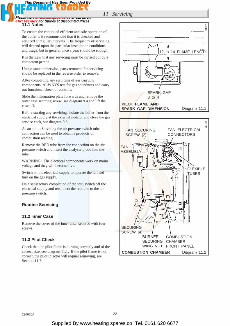
To ensure the continued efficient and safe operation ofthe boiler it is recommended that it is checked andserviced at regular intervals. The frequency of servicingwill depend upon the particular installation conditionsand usage, but in general once a year should be enough.
It is the Law that any servicing must be carried out by acompetent person.
Unless stated otherwise, parts removed for servicingshould be replaced in the reverse order to removal.
After completing any servicing of gas carryingcomponents, ALWAYS test for gas soundness and carryout functional check of controls.
Slide the information plate forwards and remove theouter case securing screw, see diagram 9.4 and lift thecase off.
Before starting any servicing, isolate the boiler from theelectrical supply at the external isolator and close the gasservice cock, see diagram 9.3.
As an aid to Servicing the air pressure switch tubeconnection can be used to obtain a products ofcombustion reading.
Remove the RED tube from the connection on the airpressure switch and insert the analyser probe into thetube.
WARNING: The electrical components work on mainsvoltage and they will become live.
Switch on the electrical supply to operate the fan andturn on the gas supply.
On a satisfactory completion of the test, switch off theelectrical supply and reconnect the red tube to the airpressure switch.
Routine Servicing
11.2 Inner Case
Remove the cover of the inner case, secured with fourscrews.
11.3 Pilot Check
Check that the pilot flame is burning correctly and of thecorrect size, see diagram 11.1. If the pilot flame is notcorrect, the pilot injector will require removing, seeSection 11.7.
3167
12 to 14 FLAME LENGTH
SPARK GAP3 to 4
3168
FAN SECURINGSCREW (2)
FAN ELECTRICALCONNECTORS
SECURINGSCREW (4)
BURNERSECURINGWING NUT
COMBUSTIONCHAMBERFRONT PANEL
FANASSEMBLY
FLEXIBLETUBES

Supplied By www.heating spares.co Tel. 0161 620 6677
23 220676A
11 Servicing
Diagram 11.3
BURNER REMOVAL Diagram 11.4
FLUEHOOD Diagram 11.5
PILOT BURNERELECTRODE ASSEMBLY
11.4 Main Burner
Slacken the flue hood securing angle wing nuts, seediagram 11.2.
Remove the combustion chamber front panel, securedwith four screws and a wing nut, see diagram 11.2.
Disconnect the pilot pipe union connector and ignitionlead, see diagram 11.3.
Separate the pilot assembly from the main burner,secured with two screws, remove by lifting upward,see diagram 11.3.
Remove the main burner from the main injector at therear. Raise the burner up and forward, easing the pilotpipe down, to clear, take care not to damage thecombustion chamber insulation or the pilot burnerassembly.
Use a vacuum cleaner or suitable stiff brush to clean theburner thoroughly, making sure that all the burner portsare clear and unobstructed.
Do not use a brush with metallic bristles.
Note: On refitting and after cleaning the heat exchangermake sure the main burner is fitted correctly, that is,located on the main injector and horizontal,see diagram 11.4.
11.5 Main Injector
With the main burner removed the maininjector can beinspected and cleaned as necessary.
If removing for cleaning do not use a wire or sharpinstrument on the hole.
Use new seal when refitting to ensure a gas tight seal ismade.
PILOT BURNERASSEMBLYSECURINGSCREW (2)
PILOTTUBING NUT
IGNITIONLEAD
PILOTINJECTOR
ELECTRODESECURINGSCREW
3169
SEALINGANGLE
ELECTRODE
3194
BURNERINJECTOR
3171FLUEHOOD FAN
RETAININGBRACKET

Supplied By www.heating spares.co Tel. 0161 620 6677
24220676A
11 Servicing
12 Fault Finding
11.6 Cleaning Heat Exchanger.
Disconnect the two electrical connections at the fan, seediagram 11.2. It is not necessary to disconnect the greenand yellow earth cable.
Disconnect the two flexible tubes from the fan, seediagram 11.2.
Remove the fan by releasing the securing screws, seediagram 11.2.
Remove the flue hood securing bracket, secured withtwo wing nuts and hook bolts, see diagram 11.2.
Remove the flue hood, see diagram 11.5.
Remove the burner as Section 11.4.
Cover the pilot assembly and main injector and place asheet of paper in the combustion chamber to catch anydebris.
Brush the heat exchanger with a suitable brush.
Do not use a brush with metallic bristles.
Remove the paper and cover from the pilot assembly andmain injector together with any debris.
When replacing, please note:
(a) Locate the fan mounting plate assembly behind theretaining bracket at the same time easing the fanoutlet into the flue elbow, see diagram 11.5.
(b) Make sure the coloured flexible tube connects to theupper connection on the fan.
(c) The polarity of the two fan electrical connections isnot important.
12.1 Electrical
Important. On completion of the Service/Fault Findingtask which has required the breaking and remaking of theelectrical connections the earth continuity, polarity, shortcircuit and resistance to earth checks must be repeatedusing a suitable multimeter.
Refer to: Neon Indicators - Aid to Fault Finding,diagram 12.1, Fault Finding, diagram 12.2 Wiring,diagram 12.5 and Functional Flow diagram 12.3.
12.2 Electrical Supply Failure
Failure of the electrical supply will cause the burner togo out. Operation will normally resume on restoration ofthe electrical supply. If the boiler does not relight afteran electrical supply failure the overheat cutoff devicemay need resetting.
To reset, pull the information panel forward on theunderside of the boiler and press the reset button, seediagram 12.4.
If the cutoff operates at any other time press the resetbutton and the burner should relight. If the fault persistsrefer to Fault Finding, diagram 12.2.
11.7 Pilot Injector
If the pilot flame is not burning correctly, it may benecessary to remove the pilot injector.
Unscrew the pilot injector from the pilot assembly.
Inspect the injector and if necessary clean only byblowing clear.
Do not use wire or sharp instrument.
When relighting check that the flame length is as shownin diagram 11.1.
11.8 Operational Checks
Check the safety valve manually by turning the knob inthe direction of the arrow.
Light the boiler, carry out operational checks and anynecessary adjustments as described in theCommissioning Section 9 of these instructions.

Supplied By www.heating spares.co Tel. 0161 620 6677
25 220676A
12 Fault Finding
NEON INDICATORS Diagram 12.1
Is neon 1 lit?
YES
YES
Is neon 2 lit?
Ignition, pilot or flame proving fault -see detailed fault finding chart.
Multi-functional control/harness problem -see detailed working? Fault finding chart.
YES
YES
Is neon 4 lit?
Is main burneroperating?
YES
Overheat cut off device tripped.Thermostat, Overheat cut off device,Water differential pressure switch,or faulty Pump. - see detailed faultfinding chart.
Is neon 3 lit?Air flow proving fault - that is fan or airpressure switch - see detailed faultfinding chart.
Fault with mains supply, PCB fuse orlow water pressure switch.
NO
NO
NO
NO
NO
NEON INDICATORS 3172
Neon Indicators - An Aid to Fault Finding
THE NEON INDICATORS ARE AN AID TO FAULT FINDING ONLY.FAILURE OF ANY OF THE NEON INDICATORS DOES NOT WARRANT THE
REPLACEMENT OF AN OTHERWISE SATISFACTORY PRINTED CIRCUIT BOARD (PCB).IF RED NEON ON FASCIA IS ILLUMINATED FILL CENTRAL HEATING SYSTEM, PRESSURE 0.7bar MIN.
System satisfactory

Supplied By www.heating spares.co Tel. 0161 620 6677
26220676A
12 Fault Finding
Before detailed checking of electrical components ensure that remote controls are calling for heat.Checking that the gas supply is free of obstructions and purged of air. Isolate the electrical supply, check allcables, connections and the printed circuit board (PCB) fuse. Check the air tubes to the air pressure switchfor kinks and splits. Switch on the electrical supply and check for correct polarity. If the red neon on the
fascia is illuminated isolate the elctrical supply. Turn the control thermostat its maximum setting.
Is neon 1 lit ?Is there 240V~between3 and 2 ?
Correct power supplyproblem
Fill Central heating systemto 0.7bar min.Does the red neon go off?
Faulty NeonIs there 240V~between N/con Low water pressureswitch and 2 ?
Is there 240V~between N/oon Low water pressureswitch and 2 ?
Is there 240V~between yellow connection on overheat device and 2 ?
Is there 240V~ betweenwhite connection on waterdifferential pressure switchand 2 ?
Does the pump run?
Is the tube to Waterdifferential pressure switchkinked or damaged.
Faulty Water differentialpressure switch. Replace.
Rectify tube or replace.
Faulty pump. Replace.
Isolate electrical supply.Check continuity of pumpcable.
Is there 240V~ betweenL and N at pump?
Check overheat reset.If satisfactory replaceoverheat device.
Faulty Low water pressureswitch. Replace.
Isolate electrical supply.Check continuity ofpurple cable.
Is there 240V~between5 and 2 ?
Is neon 2 lit ?
Is there 240V~between Con Low water pressureswitch and 2 ?
Is Red neon on fasciailluminated ?
A B
NO
NO
NO
YES
NO
YES
NO
YES
NO
YES
NO
YES
NO
NO
YES
NO
NO
YES
NO
YESNO
YES
YES
YES NO
YES
MAIN TERMINAL STRIP
Diagram 12.2
4761
/A
Supplied By www.heating spares.co Tel. 0161 620 6677
27 220676A
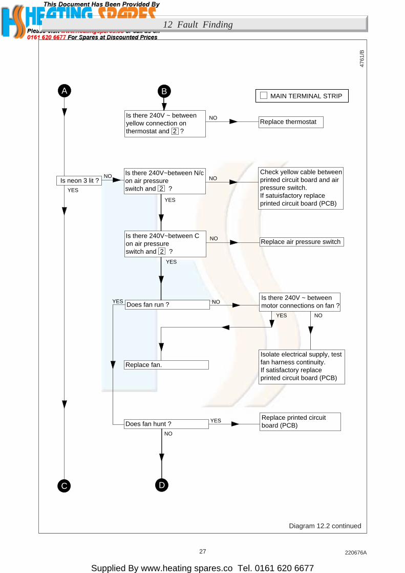
12 Fault Finding
Is neon 3 lit ?
Is there 240V ~ betweenyellow connection onthermostat and 2 ?
Replace air pressure switch
Is there 240V~between N/con air pressureswitch and 2 ?
Isolate electrical supply, testfan harness continuity.If satisfactory replaceprinted circuit board (PCB)
Is there 240V ~ betweenmotor connections on fan ?
C D
NO
NO
YES
NO
NO
YES
NO
YES
A BMAIN TERMINAL STRIP
Replace thermostat
Check yellow cable betweenprinted circuit board and airpressure switch.If satuisfactory replaceprinted circuit board (PCB)
Is there 240V~between Con air pressureswitch and 2 ?
Does fan run ?
Replace fan.
Does fan hunt ?Replace printed circuitboard (PCB)
NO
NOYES
YES
YES
NO
Diagram 12.2 continued
4761
/B
Supplied By www.heating spares.co Tel. 0161 620 6677
28220676A
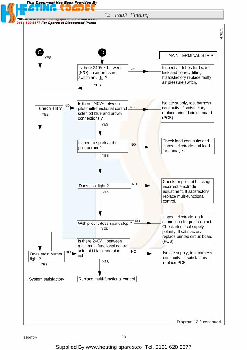
12 Fault Finding
Diagram 12.2 continued
4761
/C
Is neon 4 lit ?
Is there 240V ~ between(N/O) on air pressureswitch and N ?
Is there 240V~between pilot multi-functional controlsoleniod blue and brownconnections ?
Inspect electrode lead/connection for poor contact.Check electrical supplypolarity. If satisfactoryreplace printed circuit board(PCB)
Check for pilot jet blockage,incorrect electrode adjustment. If satisfactoryreplace multi-functionalcontrol.
NO
NO
YES
NO
NO
YES
NO
YES
C DMAIN TERMINAL STRIP
Isolate supply, test harnesscontinuity. If satisfactoryreplace printed circuit board(PCB)
Is there a spark at thepilot burner ?
Does pilot light ?
With pilot lit does spark stop ?
Isolate supply, test harnesscontinuity. If satisfactoryreplace PCB
NO
NO
YES
YES
Inspect air tubes for leakskink and correct fitting.If satisfactory replace faultyair pressure switch.
YES
YES
Replace multi-functional control
Does main burnerlight ?
System satisfactory
Is there 240V ~ betweenmain multi-functional controlsolenoid black and bluecable.
Check lead continuity andinspect electrode and leadfor damage.
NO
YES
NO
YES

Supplied By www.heating spares.co Tel. 0161 620 6677
29 220676A
12 Fault Finding
FUNCTIONAL FLOW Diagram 12.3 RESET BUTTON Diagram 12.4
3173
PUMP
LOW WATERPRESSURESWITCH
C
N/O
R N/CP
LBR
23
BLK
3 POLECONNECTOR
SPARKELECTRODE
BRBL
BL
4BR
BR
W Y
OVERHEATCUT-OFF
2
2FAN
FUSETYPEF1A
CONTROLTHERMOSTATR BL
RAIR PRESSURESWITCH
BLK
Y
BR
PILOTSOLENOID
BLK
2
2 (N)
(N)
BL
BL
(N)
BL
(N)
BL
NEONINDICATOR
BLK
WATERDIFFERENTIALPRESSURESWITCH
BL
5
N/O
N/C
C
BL
BL
MAIN SOLENOID
MAIN TERMINAL STRIP CONNECTIONS
CONTROL THERMOSTAT CONNECTIONS
CONTROL BOARD CONNECTIONS
NOTE: LOW WATER PRESSURE SWITCH
SHOWN IN UNPRESSURISED STATE
KEY
BLK BLACK
BR BROWN
BL BLUE
W WHITE
R RED
Y YELLOW
Y
W
BL
RESET BUTTON
INFORMATIONPLATE 31
74
Supplied By www.heating spares.co Tel. 0161 620 6677
30220676A
12 Fault Finding
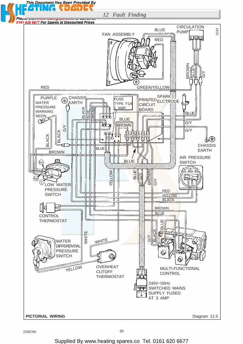
Diagram 12.5PICTORIAL WIRING
3193
CIRCULATIONPUMP
RED
BLUEFAN ASSEMBLY
GREEN/YELLOW
G/Y
BLU
E
BR
OW
N
G/Y
G/Y
CHASSISEARTH
SPARKELCTRODEPRINTED
CIRCUITBOARD
FUSETYPE F1A1 AMP
BLUEBLUE
BROWN
BLU
E
BR
OW
N
BLA
CK
PURPLE
RED
CHASSISEARTH
G/Y
BLA
CK
BLA
CK 12345
BLUE
BLU
EG
/Y
BR
OW
N
G/Y
BLACKYELLOWRED
AIR PRESSURESWITCH
NCC NC
YE
LLO
W
BROWN
WATERPRESSUREWARNINGNEON
Nc
NoC
LOW WATERPRESSURESWITCH
CONTROLTHERMOSTAT
BLUEBROWN
G/Y
BLA
CK B
LUE
OVERHEATCUTOFFTHERMOSTAT
WHITE
YELLOW
WATERDIFFERENTIALPRESSURESWITCH
240V~50HzSWITCHED MAINSSUPPLY FUSEDAT 3 AMP
MULTI-FUNCTIONALCONTROL
EL N
N E L
BLUE
WH
ITE
Supplied By www.heating spares.co Tel. 0161 620 6677
31 220676A
13 Replacement of Parts
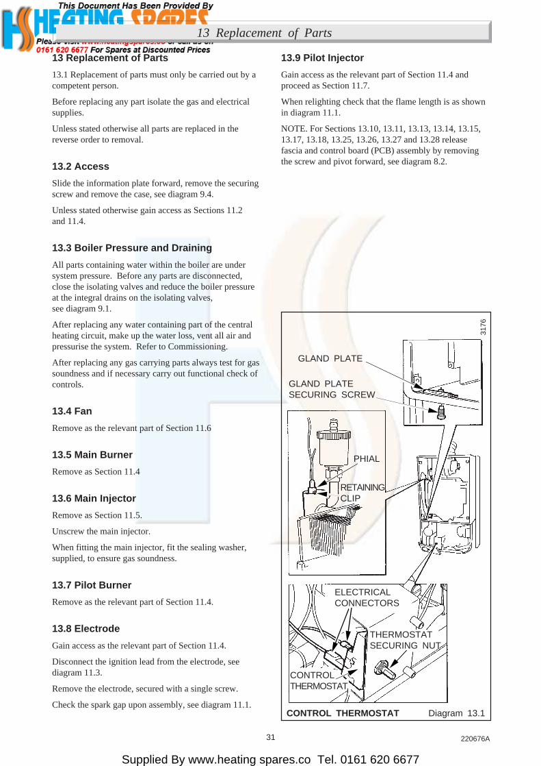
13.9 Pilot Injector
Gain access as the relevant part of Section 11.4 andproceed as Section 11.7.
When relighting check that the flame length is as shownin diagram 11.1.
NOTE. For Sections 13.10, 13.11, 13.13, 13.14, 13.15,13.17, 13.18, 13.25, 13.26, 13.27 and 13.28 releasefascia and control board (PCB) assembly by removingthe screw and pivot forward, see diagram 8.2.
CONTROL THERMOSTAT Diagram 13.1
3176
PHIAL
RETAININGCLIP
ELECTRICALCONNECTORS
THERMOSTATSECURING NUT
CONTROLTHERMOSTAT
GLAND PLATESECURING SCREW
GLAND PLATE
13 Replacement of Parts
13.1 Replacement of parts must only be carried out by acompetent person.
Before replacing any part isolate the gas and electricalsupplies.
Unless stated otherwise all parts are replaced in thereverse order to removal.
13.2 Access
Slide the information plate forward, remove the securingscrew and remove the case, see diagram 9.4.
Unless stated otherwise gain access as Sections 11.2and 11.4.
13.3 Boiler Pressure and Draining
All parts containing water within the boiler are undersystem pressure. Before any parts are disconnected,close the isolating valves and reduce the boiler pressureat the integral drains on the isolating valves,see diagram 9.1.
After replacing any water containing part of the centralheating circuit, make up the water loss, vent all air andpressurise the system. Refer to Commissioning.
After replacing any gas carrying parts always test for gassoundness and if necessary carry out functional check ofcontrols.
13.4 Fan
Remove as the relevant part of Section 11.6
13.5 Main Burner
Remove as Section 11.4
13.6 Main Injector
Remove as Section 11.5.
Unscrew the main injector.
When fitting the main injector, fit the sealing washer,supplied, to ensure gas soundness.
13.7 Pilot Burner
Remove as the relevant part of Section 11.4.
13.8 Electrode
Gain access as the relevant part of Section 11.4.
Disconnect the ignition lead from the electrode, seediagram 11.3.
Remove the electrode, secured with a single screw.
Check the spark gap upon assembly, see diagram 11.1.

Supplied By www.heating spares.co Tel. 0161 620 6677
32220676A
OVERHEAT CUT-OFF Diagram 13.2
Diagram 13.3SAFETY VALVE /PRESSURE GAUGE
13.10 Control Thermostat
Gain access as Section 13.2
Remove the control knob and fascia by removing thescrews, see diagram 8.2.
Remove the thermostat securing nut, see diagram 13.1.
Remove the electrical connections from the thermostatbody.
Slacken but do not remove the gland plate.
Now remove the phial retaining clip and then thethermostat phial from the pocket, see diagram 13.1.
When refitting, make sure that the thermostat capillary iscorrectly routed and the phial covered with heat sinkcompound, before it is secured in the pocket, by the phialretaining clip.
Reconnect the electrical connections, see diagram 12.5.
13.11 Overheat Cutoff: diagram 13.2
Remove the electrical connections from the cutoff body.
Remove the capillary securing clamp.
Remove the locknut securing the overheat cutoff to thebracket and withdraw the assembly.
13.12 Ignition Lead: diagram 11.3
Slacken but do not remove the sealing angle securingscrew.
Disconnect the ignition lead at both ends and withdraw.
When refitting push the lead through the seal from thetop and make sure that the clear end is fitted to the sparkelectrode and that the lead follows the same route, beingsecured in the same manner, as the original.
Take care not to damage the seal of the sealing angle.
13.13 Pressure Gauge: diagram 13.3
Release the water pressure and drain the boiler, refer toSection 13.3.
Disconnect the pressure gauge connection from thesafety valve, discard the washer.
Remove the pressure gauge secured with the retainingspring tabs from the bracket.
Fit the supplied washer under the pressure gaugeconnection when refitting to the safety valve.
3177
PLASTICRETAININGCLIP
CAPILLARYSECURINGCLAMPSCREW
VIEWED FROM REAR
ELECTRICALCONNECTIONS
OVERHEATCUT-OFFLOCKNUT
UNION NUTCONNECTION
PRESSUREGUAGECONNECTION
SAFETYVALVE
FIBREWASHER
PRESSUREGUAGE
SECURINGSPRING TAB (2)
13 Replacement of Parts
3178

Supplied By www.heating spares.co Tel. 0161 620 6677
33 220676A
Diagram 13.4 Diagram 13.6WATER DIFFERENTIALPRESSURE SWITCH CONTROL BOARD (P.C.B)
13.14 Safety Valve: diagram 13.3
Release the water pressure and drain the boiler, refer toSection 13.3.
Remove the pressure gauge connection as Section 13.3.
Disconnect the union nut to release the discharge pipe.
Place a spanner on the hexagon on the volume vessel andbreak the union nut connection to release and thenunscrew the safety valve.
When refitting use a proprietary sealant to seal the joint.
When fitting use a new washer for the pressure gaugeconnection.
13.15 Water Differential Pressure Switch:diagram 13.4
Release water pressure as Section 13.3.
Remove the two electrical connections and release theunion connections, and remove the pressure switch,complete with the flexible tubing.
Fit the flexible tubing to the new pressure switch.
Refer to diagram 12.5 when remaking the electricalconnections.
13.16 Low Water Pressure Switch:diagram 13.5
Release the water pressure and drain the boiler, refer toSection 13.3.
Disconnect the electrical connectors at the micro-switch.
Remove the pressure switch.
Diagram 13.5LOW C.H. WATERPRESSURE SWITCH
Use a proprietary sealant to seal the connection.
Make sure that the switch is positioned as shown.
Refer to wiring diagram 12.5 when making the electricalconnections.
13 Replacement of Parts
WATER DIFFERENTIALPRESSURE SWITCH
UNION
UNION
HOSEASSEMBLY
ELECTRICALCONNECTORS
UNIONCONNECTOR
3179
3181SUPPORT
POST (4)
PLASTICRETAININGCLIP
TERMINALCONNECTIONS
TERMINALBLOCKSECURINGSCREW (2)
CHASSIS EARTHCONNECTION
CABLECONNECTION
CABLETIE
CONTROL BOARD P.C.B.
MULTI PINCONNECTORS
3180LOW C.H.
WATRE PRESSURESWITCH
ELECTRICALCONNECTORS

Supplied By www.heating spares.co Tel. 0161 620 6677
34220676A
Diagram 13.8PUMP
13.17 Control Board (PCB): diagram 13.6
Disconnect all multi-pin connectors.
Remove the blue and brown cables from terminals 4 and5 also disconnect the yellow cable from the controlthermostat and the white cable from the overheat cutoffand the chassis earth cable.
Remove the terminal block and cables complete.
Remove the ignition lead.
Remove the printed circuit board from the support posts,noting their correct positions. Great care must be takenwhen handling the board.
To connect the multi-pin connectors, cables and terminalblock correctly, refer to diagram 12.5
Diagram 13.7
13.18 Multifunctional Control and PilotSolenoid: diagram 13.7
Disconnect all electrical connections at themultifunctional control.
Remove the four securing screws from the left hand sideof the multifunctional control and pilot pipe, take care asthere is a restrictor in this pipe.
Support the multifunctional control, disconnect the unionnut of the gas service cock and remove themultifunctional control complete with inlet pipe.
Separate the multifunctional control from the pipe, fourscrews, noting the fitted position.
Discard the “O” rings and fit the new ones supplied.
To reconnect the connections refer to diagram 12.5
Light and adjust the boiler as necessary, refer toSection 9.
Pilot Solenoid
Disconnect the electrical connections at the solenoid,remove the retaining clip and solenoid.
When reconnecting refer to diagram 12.5.
3195
SOLENOIDRETAININGCLIP
SOLENOID
ELECTRICALCONNECTORS
PILOTSOLENOID
GAS SUPPLYPIPE UNION
ELECTRICALCONNECTORS
SECURINGSCREWS (8)
PILOTPIPEUNIONCONNECTOR
MULTI-FUNCTIONAL CONTROL
3183
UNIONCONNECTOR
IN-LINEELECTRICALCONNECTORS
UNIONCONNECTOR
ENDSCREW
13 Replacement of Parts
Supplied By www.heating spares.co Tel. 0161 620 6677
35 220676A
Diagram 13.9HEAT EXCHANGER
13.19 Pump: diagram 13.8
Release the water pressure and drain, refer toSection 13.3.
Disconnect the “in-line” connections at the pump.
Disconnect the pump at the union connections.
Discard the sealing washers and fit the new onessupplied.
When fitting the replacement make sure that the flowdirection arrow is pointing upward.
Set the flow adjuster to position 3, see Section 2.6.
Note: Should the pump fail to operate, and all is in orderbut the pump still does not operate, remove the endscrew, turn the pump spindle to release any temporaryseizure. DO NOT HIT THE SPINDLE.
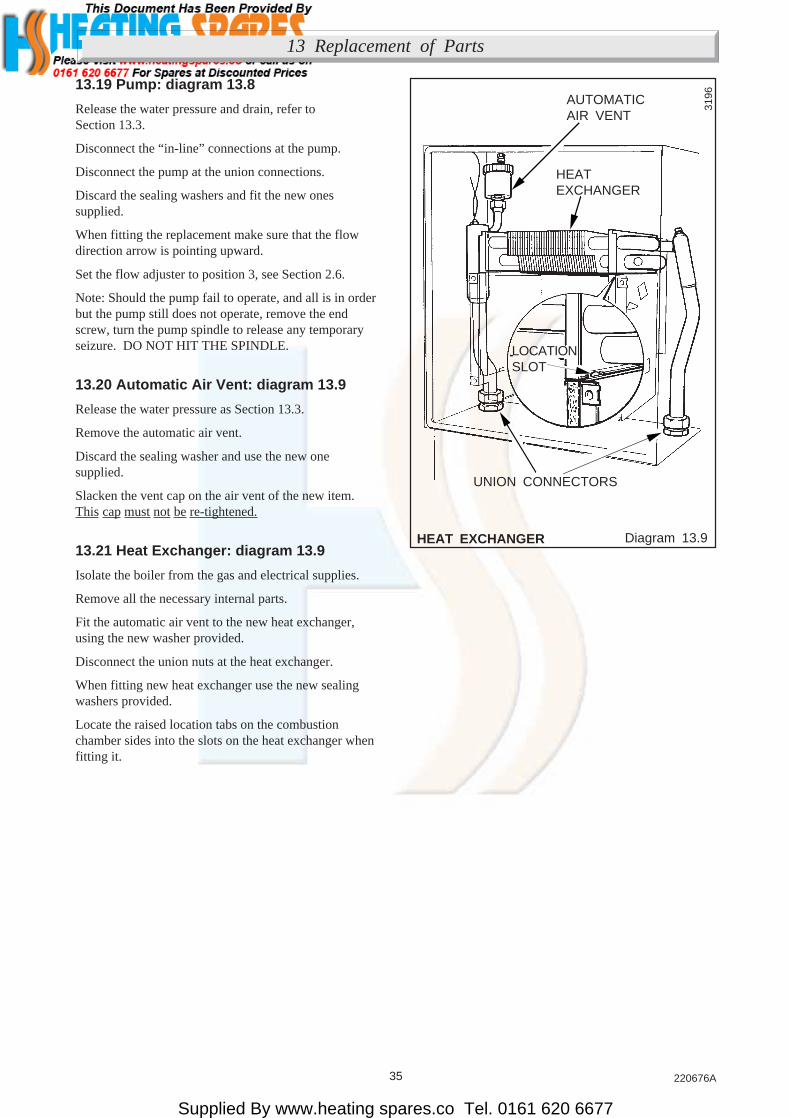
13.20 Automatic Air Vent: diagram 13.9
Release the water pressure as Section 13.3.
Remove the automatic air vent.
Discard the sealing washer and use the new onesupplied.
Slacken the vent cap on the air vent of the new item.This cap must not be re-tightened.
13.21 Heat Exchanger: diagram 13.9
Isolate the boiler from the gas and electrical supplies.
Remove all the necessary internal parts.
Fit the automatic air vent to the new heat exchanger,using the new washer provided.
Disconnect the union nuts at the heat exchanger.
When fitting new heat exchanger use the new sealingwashers provided.
Locate the raised location tabs on the combustionchamber sides into the slots on the heat exchanger whenfitting it.
3196
LOCATIONSLOT
AUTOMATICAIR VENT
HEATEXCHANGER
UNION CONNECTORS
13 Replacement of Parts

Supplied By www.heating spares.co Tel. 0161 620 6677
36220676A
13 Replacement of Parts
Diagram 13.10COMBUSTIONCHAMBER INSULATION
13.22 Combustion Chamber Insulation:diagram 13.10
Remove the securing clip and insulation panel.
Take care when sliding the replacement insulation intoposition securing it with the original clip.
The rear insulation cannot be removed until the heaterexchanger is removed, see Section 13.21, then slide theinsulation from behind the heat exchanger.
3186
INSULATION PANEL
INSULATIONRETAININGCLIP
COMBUSTION CHAMBER FRONT PANEL
COMBUSTIONCHAMBER FRONTPANEL
3197
SIDE INSULATIONPANEL(S)
REAR INSULATIONPANEL(S)

Supplied By www.heating spares.co Tel. 0161 620 6677
37 220676A
13 Replacement of Parts
Diagram 13.11EXPANSION VESSEL
13.23 Expansion Vessel: diagram 13.11
Renewal of the expansion vessel requires the removal ofthe boiler from the wall. As an alternative, in certaincircumstances, a separate expansion vessel of the samespecification may be connected as close as possible tothe boiler, leaving the original in position.
Isolate the boiler from the gas and electrical supplies.
Release the water pressure and drain, as Section 13.3.
Remove the fan from the flue hood, see Section 11.6.
Disconnect the flue elbow, by reversing the instructionin Section 8.2.
Disconnect the boiler water connections union nuts,see diagram 5.3.
Disconnect the gas service cock, see diagram 5.3.
Disconnect the electrical plug, see diagram 8.3.
Remove the boiler from the mounting frame securedwith two screws at the top, see diagram 5.4. Pull theboiler from the isolating valves and clips at the bottom.Unhook the boiler at the top and withdraw it forward.
Carefully lay the boiler down on its side to gain access tothe expansion vessel.
Disconnect the union nut connection.
Remove the expansion vessel, secured with threeclamps.
Discard the sealing washers and use the new onessupplied.
Connect the union nut, when fitting the expansion vessel,before clamping it.
3187UNION NUT
CONNECTION ANDSEALING WASHER
EXPANSION VESSEL
CLAMPINGSCREW (3)

Supplied By www.heating spares.co Tel. 0161 620 6677
38220676A
13.24 Pilot Viewing Window: diagram 13.12
Remove the two screws and then the window.
When replacing take care not to damage the gasket.
13.25 Inner Case Seal: diagram 13.12
Gain access as Section 13.2.
When removing seal make sure that all the old adhesiveis removed.
When fitting the new seal make sure that it fits correctlyand has not buckled.
13 Replacement of Parts
Diagram 13.12PILOT VIEWINGWINDOW / INNER CASE
3188
FRAME
INNERCASE
INNERCASESEAL
PILOTVIEWINGWINDOW
SECURINGSCREW (2) GLASS GASKET
Supplied By www.heating spares.co Tel. 0161 620 6677
39 220676A
13 Replacement of Parts
Diagram 13.14
Diagram 13.13
BYPASS VALVE
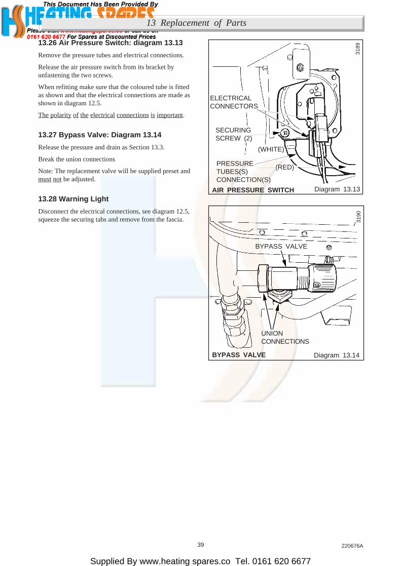
13.26 Air Pressure Switch: diagram 13.13
Remove the pressure tubes and electrical connections.
Release the air pressure switch from its bracket byunfastening the two screws.
When refitting make sure that the coloured tube is fittedas shown and that the electrical connections are made asshown in diagram 12.5.
The polarity of the electrical connections is important.
13.27 Bypass Valve: Diagram 13.14
Release the pressure and drain as Section 13.3.
Break the union connections
Note: The replacement valve will be supplied preset andmust not be adjusted.
13.28 Warning Light
Disconnect the electrical connections, see diagram 12.5,squeeze the securing tabs and remove from the fascia.
3189
(RED)
ELECTRICALCONNECTORS
SECURINGSCREW (2)
(WHITE)
PRESSURETUBES(S)CONNECTION(S)
AIR PRESSURE SWITCH
3190
BYPASS VALVE
UNIONCONNECTIONS

Supplied By www.heating spares.co Tel. 0161 620 6677
40220676A
14 Spare Parts
14.1 Part Identification
The key number in diagram 14.1 and the first column ofthe list will help to identify the spare part.
14.2 Ordering
When ordering any spare part, please quote the partnumber and the description from the list together withthe model name and serial number information from thedata label. The data label is positioned at the top right ofthe inner case.
If ordering from the local gas company also quote theGC number of the appliance from the data label and theGC number of the spare part, from the list.
Key No Part No Description GC No
1 800628 Fan assembly 278 259
2 800241 Main injector - 30 313 568
3 230385 Pilot burner 387 159
4 203517 Pilot injector 376 968
5 800211 Hose Assembly 313 482
6 800205 Thermostat - control 397 982
7 800206 Thermostat knob 313 484
8 230212 Thermostat - cutoff 397 981
9 WW4614 Ignition lead 136 399
10 800134 Pressure gauge assembly 313 294
11 800207 Control board (PCB) 313 475
12 800240 Multifunctional control 313 567
13 202015 Fuse 334 750
14 208302 Sight glass 312 419
15 900834 Air pressure switch 385 860
16 800153 Automatic air vent 313 285
17 800149 Safety valve 397 677
18 800209 Bypass valve 313 451
19 800210 Water differential pressure switch 313 452
20 441581 Low central heating water pressure neon indicator 313 589
21 800150 Low central heating water pressure switch 319 862

Supplied By www.heating spares.co Tel. 0161 620 6677
41 220676A
14 Spare Parts
Diagram 14.1
3198
19
3
4
17
2
14
18
16
19
19
5
13
11
1521
10
20
7
8
1212
6
18

Supplied By www.heating spares.co Tel. 0161 620 6677
42220676A
Supplied By www.heating spares.co Tel. 0161 620 6677
43 220676A
Control of Substances Hazardous to Health.
Information for the Installer and Service Engineer.Under Section 6 of The Health and Safety at Work Act 1974, we are required to provide informationon substances hazardous to health.The adhesives and sealants used in this appliance are cured and give no known hazard in this state.
INSULATION PADS/CERAMIC FIBRE, GLASSYARN, MINERAL WOOLThese can cause irritation to skin, eyes and the respiratory tract.If you have a history of skin complaint you may be susceptible to irritation. High dust levels areusual only if the material is broken.Normal handling should not cause discomfort, but follow normal good hygiene and wash yourhands before eating, drinking or going to the lavatory.If you do suffer irritation to the eyes or severe irritation to the skin seek medical attention.
THERMOSTATSThese contain very small amounts of dichlorotrifluoroethane in the sealed phial and capillary.If broken, under normal circumstances the fluid does not cause a problem.If there is irritation to the eyes or skin then seek medical attention.
CUT-OFF DEVICESThese contain a very small amount of ethylene glycol and methanol in the capillary.If broken, under normal circumstances the fluid does not cause a problem, but in cases of skin oreye contact, wash with cold water.If swallowed drink plenty of water and seek medical attention.

Supplied By www.heating spares.co Tel. 0161 620 6677
44220676A
Because of our constant endeavour for improvement details may vary slightly from those in the instructions