installation and servicing instructions - keston boilers · the keston condensing boiler is unique...
TRANSCRIPT

Fan Powered High Efficiency Condensing Gas Boiler
Installation And Servicing Instructions
Keston 50 - GC No 41 930 01Keston 60 - GC No 41 930 02Keston 80 - GC No 41 930 03
PI No. : 87AQ306These instructions must be left either with the user or next to
the household gas meter.
34 West Common RoadHayes, Bromley, Kent BR2 7BX
Tel. (44)0208 462 0262 Fax. (44)0208 462 4459
WD50/2/1997 The Keston 50, 60 & 80 Condensing Boilers
0087

CONTENTS
Section Description
1 GENERAL INSTRUCTION1.1 Description1.2 Boiler Schematic1.3 Related Documents1.4 Performance Data1.5 General Data
2 BOILER LOCATION2.1 Dimensions & Minimum Clearances2.2 Service Connections2.3 Position2.4 Electrical2.5 Boiler Size Selection2.6 Gas Supply2.7 Water Systems2.8 Flue System2.9 Air Supply2.10 Compartment Installation2.11 Condensate Drainage2.12 Radiant Floor Heating2.13 Low Water Volume Boiler vs. Cast Iron Boiler2.14 Determine Radiation Needed Room-By-Room
3 INSTALLATION OF THE BOILER3.1 Wall Mounting Bracket3.2 Mounting The Boiler3.3 Assembly Practice3.4 Installing Flue And Air Pipes3.5 Condensate Drainage3.6 Water System3.7 Gas Supply3.8 Electrical Supply3.9 Exchanging A Boiler
4 COMMISSIONING OF THE BOILER4.1 Initial Flushing4.2 Gas Supply4.3 Electrical Installation4.4 LP Gas Conversion4.5 Initial Firing4.6 Hot Flushing4.7 Checking The Gas Pressure
WD50/2/1997 The Keston 50, 60 & 80 Condensing Boilers
Page : i

4.8 Timing The Gas Meter4.9 Handing Over To The User
5 FAULT FINDING5.1 Electrical Control Sequence5.2 Fault Finding Flow Chart5.3 Continuity Checking5.4 Functional Flow Wiring Diagram5.5 Electrical Wiring Diagram5.6 Illustrated Wiring Diagram5.7 Exploded Assembly Diagrams
6 SERVICING6.1 Pre Service Checks6.2 Recommended Routine Service
7 REPLACEMENT OF PARTS7.1 General7.2 Precautions7.3 Access7.4 Electrical7.5 Gas Orifice7.6 Spark Ignition/Flame Detection Electrode7.7 Burner Head & Burner7.8 Heat Exchanger7.9 Air Filter7.10 Condensate Trap7.11 Pressure Gauge7.12 Sight Glass7.13 HT Ignition Lead7.14 Air Vent7.15 Air Orifice
8 SPARE PARTS LISTINGS
WD50/2/1997 The Keston 50, 60 & 80 Condensing Boilers
Page : ii

1. GENERAL INSTRUCTION
1.1 DESCRIPTION
The Keston Condensing Boiler is unique in its concept and design. While the applicationfor which the boiler was designed is the same as those which other boilers are used theKeston boiler has the added advantage of very high efficiency, and small diameter plasticflue which can be extended to 10 metres horizontally or vertically.
The Keston uses a high power combustion blower to deliver a pre-mix of gas and air to adownward firing burner in a high efficiency, single pass heat exchanger.
Normally the combustion temperature of the air gas mixture is around 1800oC but theKeston achieves combustion at an amazing 1000oC thereby reducing the NOx emissionsdown to an incredible less than 5 p.p.m.
The flue system is room sealed and fan powered. The ignition is direct spark and fullyautomatic. The boiler housing is not waterproof. The boiler should be installed in aposition where it will always be dry. A small air intake point is incorporated within theappliance cabinet to ensure that the interior of the cabinet is maintained under a slightnegative pressure. This is a safety feature to ensure no products may leak out of thecabinet into the installation space.
The boiler is suitable for connection to open vented or sealed systems. The system mustbe pumped central heating or pumped central heating with combined indirect domestic hotwater. Gravity circuits must not be used.
The boiler has a primary heat exchanger which, through its combustion chamber andcorrugated coil, transfers the heat produced in the hot gases of combustion process intothe circulating water. Head characteristics of the boiler coil must be taken intoconsideration when calculating the pump size.
The Keston boiler is not a high water content boiler and does not contain the metal mass,or water volume, of a cast iron or steel boiler. This boiler is of low mass and low watercontent and therefore responds faster when there is a call for heat. This feature requires ahigher water pumping rate through the boiler otherwise localised boiling will occur withinthe boiler.
Allow a pressure drop through the boiler of 3.2 ft head and a water flow of 4.2 gallons (19litres) per minute for the Keston 50, 4.3 ft head and 5 gallons (23 litres) per minute for theKeston 60 and 9 ft head and 6.7 gallons (30.5 litres) per minute for the Keston 80.
The boiler selected must be sized relative to the total calculated heat loss of the building.The boiler rated output should not be greater than the total required to make up thecalculated heat loss plus the heat required to provide domestic hot water. If there arespecial conditions such as excessive domestic hot water usage consult the manufacturer.
1.2 BOILER SCHEMATIC
Air is drawn into the boiler through a 40mm (BS5255) muPVC pipe. The air flow is provedby a differential pressure across the air control orifice.
Gas is mixed with combustion air at the inlet to the fan. The gas flow is regulated by anorifice located in the housing downstream of the gas valve.
WD50/2/1997 Chapter 1 : General Instruction The Keston 50, 60 & 80 Condensing Boilers
Installation & Servicing InstructionsPage : 1

WD50/2/1997 Chapter 1 : General Instruction The Keston 50, 60 & 80 Condensing Boilers
Installation & Servicing InstructionsPage : 2
Figure 1.2 Boiler Schematic
LEGEND
1 Heating Return
2 Water Return Thermostat
3 Downstream Pressture Test Nipple
4 Flame Ignition/Sensing Probe
5 Burner
6 Automatic Air Vent
7 High Limit Thermostat
8 Heating Flow
9 Flue Exhaust
10 Air/Gas Flexible Connector
11 Air Filter
12 Air Inlet Flexible Connector
13 Ignition Control Box
14 Gas Low Pressure Switch
15 Gas Multifunctional Control
16 Gas Inlet Flexible Connector
17 Air Pressure Switch
18 Combustion Blower
19 Condensate Trtap
20 Flue Overheat Thermostat
21 Heat Exchanger
22 Flow Overheat Thermostat
23 Water Low Pressure Switch
24 Combustion Test Point

The gas and air are thoroughly mixed in the blower and fed into the burner located at thetop end of the heat exchanger module. The gas and air mixture is ignited by a direct sparkignition control system and burns with a blue flame just off the surface of the burner. Asthe hot products of combustion pass downwards, they are cooled, exchanging heat withthe circulating water which enters the heat exchanger coil at the bottom of the heatexchanger.
When the return water temperature is below 54oC, part of the water vapour in thecombustion products will condense inside the heat exchanger, thus increasing the boilerefficiency. This condensate falls to the bottom of the heat exchanger where it is separatedfrom the flue gases and exits from the boiler through the condensate drain. Anycondensate formed in the flue runs back down the flueway and is drained at the base ofthe flue connection to the heat exchanger.
The condensate is very slightly acidic (about the same acidity as vinegar) and should bepiped in a plastic pipe. It is not harmful to the waste disposal system and may be disposedof as normal waste water.
The flue gases are piped in a 40mm muPVC pipe to the outside. The temperature of theflue gases are usually less than 10oC above the temperature of the return water. The fluepipe should be terminated outside the building from where they cannot re-enter thebuilding or any other adjacent building or cause a nuisance by pluming.
The heating level may be controlled by room thermostats, hot water cylinder thermostatsand programmer time clocks.
1.3 RELATED DOCUMENTS
The Keston Condensing Boiler must be installed in accordance with the current issue ofthe Gas Safety (Installation and Use) Regulations, current IEE Wiring Regulations, Safetydocument no. 635 - The Electricity At Work Regulations 1989, Building Regulations,Building Standards (Scotland) Consolidation, and the Bye Laws of the local WaterUndertaking.
In addition, due account must be taken to the following Codes Of Practice:
BS 6891 : Gas SuppliesBS 6798 : Installation Central Heating BoilersBS 5449 : Installation Pumped Central HeatingBS 5546 : Installation Domestic Hot WaterBS 5440.1 : FluesBS 5440.2 : Air SupplyBS 5482.1 : Domestic Propane & Butane Burning InstallationsBS 7074.1 : Expansion VesselsBS 7593 : Treatment of Water in Hot Water Central Heating
SystemsBS 7671 : Requirements for Electrical Installations. IEE Wiring
Regulations 16th Edition.
For Timber Framed Buildings, British Gas Publications DM2. Also British GasPublications 'Guidance Notes For The Installation Of Domestic Gas CondensingBoilers' and 'Specification For Domestic Wet Central Heating Systems'.
WD50/2/1997 Chapter 1 : General Instruction The Keston 50, 60 & 80 Condensing Boilers
Installation & Servicing InstructionsPage : 3
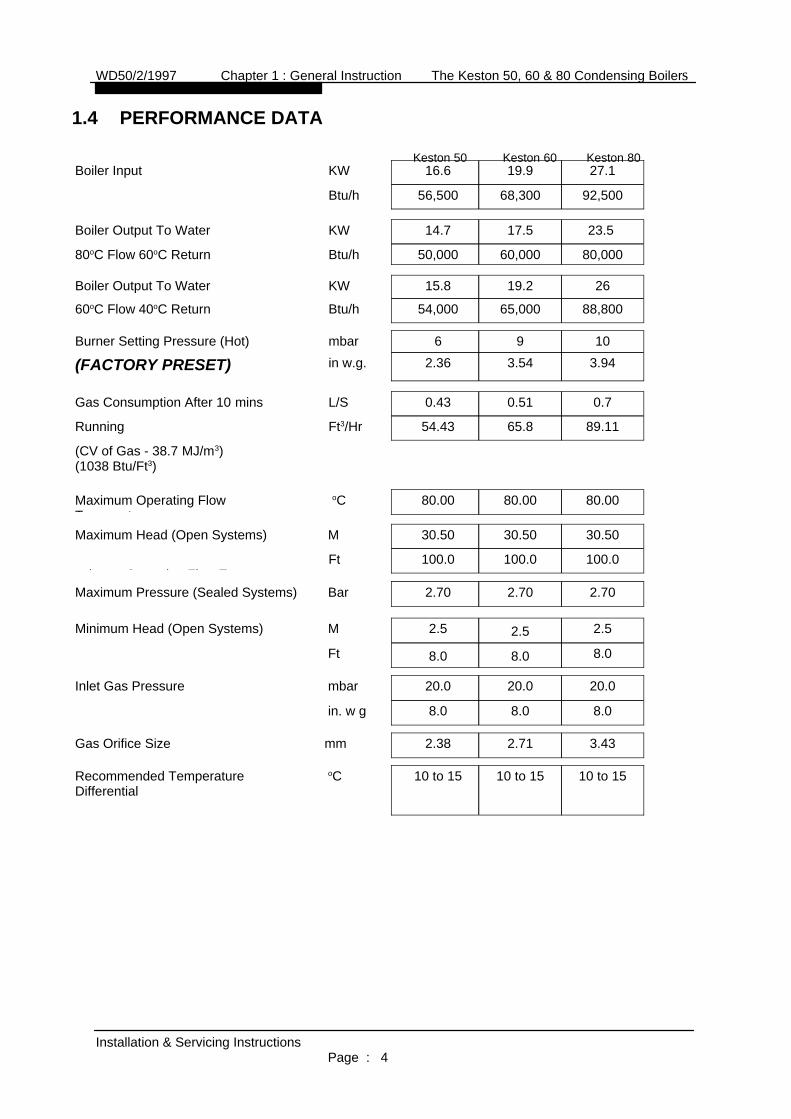
1.4 PERFORMANCE DATA
Keston 50 Keston 60 Keston 80
10 to 1510 to 1510 to 15oCRecommended TemperatureDifferential
3.432.712.38mmGas Orifice Size
8.08.08.0in. w g
20.020.020.0mbarInlet Gas Pressure
8.08.08.0Ft
2.52.52.5MMinimum Head (Open Systems)
2.702.702.70BarMaximum Pressure (Sealed Systems)
100.0100.0100.0Fti O ti Fl T t
30.5030.5030.50MMaximum Head (Open Systems)
80.0080.0080.00 oCMaximum Operating FlowT t
(CV of Gas - 38.7 MJ/m3) (1038 Btu/Ft3)
89.1165.854.43Ft3/HrRunning
0.70.510.43L/SGas Consumption After 10 mins
3.943.542.36in w.g.(FACTORY PRESET)1096mbarBurner Setting Pressure (Hot)
88,80065,00054,000Btu/h60oC Flow 40oC Return
2619.215.8KWBoiler Output To Water
80,00060,00050,000Btu/h80oC Flow 60oC Return
23.5 17.514.7KWBoiler Output To Water
92,50068,30056,500Btu/h
27.119.916.6KWBoiler Input
WD50/2/1997 Chapter 1 : General Instruction The Keston 50, 60 & 80 Condensing Boilers
Installation & Servicing InstructionsPage : 4

1.5 GENERAL DATA
Keston 50 Keston 60 Keston 80
3.30 litres2.35 litres2.35 litresWater Content
Rear panel inside caseRear panel inside caseRear panel inside caseData Badge Posn
50 kg (110 lbs)44 kg (97 lbs)44 kg (97 lbs)Weight - Empty
52 kg (114 lbs)46 kg (101 lbs)46 kg (101 lbs)Weight - Full
5 Amps5 Amps5 AmpsExt. Fuse Rating
175 W140 W140 WPwr Consumption
230V 50Hz230V 50 Hz230V 50 Hz Power Supply
28 mm Copper28 mm Copper28 mm CopperReturn Connection
28 mm Copper28 mm Copper28 mm CopperFlow Connection
0.5 inch BSPT Male(15mm to gas cock)
0.5 inch BSPT Male(15mm to gas cock)
0.5 inch BSPT Male(15mm to gas cock)
Gas SupplyConnection
Keston FilterKeston Filter Keston FilterFilter
Tridelta FS 6717 - 1428Tridelta FS 6717 - 1428Tridelta FS 6717 - 1428Air Pressure Switch
Full Sequence ControlFull Sequence ControlFull Sequence ControlIgnition
RAM ElectronicsRAM ElectronicsRAM ElectronicsDirect Spark
0.18 KW 2900 RPM0.18 KW 2900 RPM0.18 KW 2900 RPM
Type LPB 102 220/240Type LPB 102 220/240Type LPB 102 220/240
KestonKestonKestonCombustion Fan
36E Series36E Series36E Series
White RogersWhite RogersWhite Rogers Gas Control
Keston PremixKeston PremixKeston PremixMain Burner
WD50/2/1997 Chapter 1 : General Instruction The Keston 50, 60 & 80 Condensing Boilers
Installation & Servicing InstructionsPage : 5

2. BOILER LOCATION
2.1 DIMENSIONS AND MINIMUMCLEARANCES
The boiler must be installed inminimum clearances shown to allowsubsequent servicing, and safeoperation.
2.2 SERVICE CONNECTIONS
Gas, water, air and flue pipe,condensation, and electricalconnections are as shown. Gas : 0.5inch BSP male. Flow/Return : 28 mmcopper.
2.3 POSITION
The Keston is not suitable for externalinstallation. The boilermay be installed in anyroom or internal space,although particularattention is drawn to therequirements of thecurrent IEE WiringRegulations and, inScotland, the electricalprovisions of the BuildingRegulations applicable inScotland, with respect tothe installation of theboiler in a room orinternal space containinga bath or shower.
Where a room-sealedappliance is installed in a
WD50/2/1997 Chapter 2 - Boiler Connections The Keston 50, 60 & 80 Condensing Boilers
Installation & Servicing InstructionsPage : 6
All dimensions in mm.
254
305
127
Figure 2.1.1
Minimum Clearances
11
All dimensions in mm.
500
300Figure 2.1.2
Dimensions
712 (K
esto
n 50
& 60
)
Air Intake
Flue
Return Flow
890
(Kes
ton 8
0)
2747
Top View
68
3037
97
Base View
Service Connection Locations
All dimensions are in mm.
60
405
237
181

room containing a bath or shower, any electrical switch or appliance control, utilisingmains electricity, should be so situated that it cannot be touched by a person using thebath or shower.
Compartment installation is permitted - such compartments must be constructed inaccordance with BS 6798.
The wall on which the boiler is mounted must be of suitable load bearing capacity andmust be non-combustible.
Important : It is not recommended to install the boiler on a studded wall or similar - it ispossible that the vibration from the fan would be amplified and transmitted to other partsof the house.
Chimneys not used forventing any otherappliance may be used.
Figure 2.3
Condensate drain
Secure air & flue pipes atchimney outlet.
[NB: Refer to Section 2.8.3]
The Keston can be located virtually anywhere desired provided that all regulations aremet. Because of the boiler's compact size and venting flexibility, the installation is notlimited to a boiler room setting. Before locating the boiler near a living space considerwhether the sounds generated by the boiler will be objectionable. Sound levels from theboiler are no greater than from any other type of high-efficiency boiler but even minimallevels may be objectionable if located near a bedroom or in a living area.
2.4 ELECTRICAL
2.4.1 Electrical Connections
The boiler must be connected to a 230V ~ 50Hz supply, fused at 5A. All external controls and wiring must be suitable for mains voltage . Wiring external tothe boiler must be in accordance with current I.E.E wiring regulationsand local regulations.
WD50/2/1997 Chapter 2 - Boiler Connections The Keston 50, 60 & 80 Condensing Boilers
Installation & Servicing InstructionsPage : 7

The method of connection to the mains electricity supply must facilitate complete electrical isolation of the boiler complying with the requirements of BS1363.
The appliance must be connected to the supply via a fused double-pole switch,having at least 3mm (1/8 inch) contact separation in both poles, serving only theboiler and the system controls.
The connection point to the mains supply should be readily accessible andadjacent to the boiler, except for rooms containing a bath or a shower. Refer tosection 2.3 Position.
2.4.2 External Wiring & Controls
1. The boiler is deisgned so that all control wiring is external to the boiler.Hence, any programmers or room thermostats etc must act by switchingthe 230V supply to the boiler.
2. System designs which allow the boiler to fire when there is no pumpedcirculation must NOT be used.
3. A programmer may be used with zone valves to give independentcontrol of central heating and hot water.
2.5 BOILER SIZE SELECTION
The size of the boiler to be used is determined by the total calculated heat loss of thebuilding. Match the calculated heat loss with the boilers rated output. If a boiler is installed with an output rating greatly exceeding the total capacity of the distributionsystem the efficiency of the boiler will be reduced. If the boiler is to be used to heatdomestic hot water no additional capacity is normally needed for the average residentialinstallation since there is usually some excess capacity in the boiler as water heating isan intermittent load.
2.6 GAS SUPPLY
A gas meter should be connected to the service pipe by the local gas supplier or theircontractor. An existing meter should be checked preferably by the gas region to ensurethat the meter is adequate to deal with the rate of gas supply required. Installation pipesshould be fitted in accordance with BS 6891.
Minimum/Maximum Natural Gas Pressure:Natural gas pressure before the gas valve must be maintained at 20 mbar (8 in w.g)while the boiler is running.Gas pressures above or below this level will lead to problems associated with the gasvalve's internal pressure regulator.
Minimum/Maximum L P Gas Pressure:LPG pressure must be maintained between 31.5 mbar (12.4 in w.g) and 37.6 mbar (14.8in w.g) while the boiler is running.Gas pressures above or below these levels will lead to problems associated with the gasvalve's internal pressure regulator.
Supply pipes to the boiler must not be sized less than the boiler inlet connection (15 mm)Due consideration must be given to the supply pressure to other gas appliances in thepremises.
WD50/2/1997 Chapter 2 - Boiler Connections The Keston 50, 60 & 80 Condensing Boilers
Installation & Servicing InstructionsPage : 8

A gas cock is supplied loose with the boiler. This cock should be fitted in the gas line tothe boiler as close to the boiler as possible so that it is easily identified as the cock toisolate the boiler.
2.7 WATER SYSTEMS
All piping must be installed in accordance with all applicable local and Water SupplyBylaws for forced hot water heating systems.Consideration must be given to pipe capabilities and pressure drop through the piping.Water treatment must be carried out to BS 7593 : Treament of Water in Hot WaterCentral Heating Systems.Pump isolating valves must be positioned as close to the pump as possible.
a The Keston is suitable for use on open, vented water systems with combined feedand vent.
b It is preferable for use on sealed water systems, provided the appropriatecomponents required (see Section 2.7.2 Sealed Systems) are included in thesystem.
c Any system must be thoroughly flushed clean of grease, dirt and debris, prior toconnection with the boiler. A trap may be installed in the flow line to collect anysolder, or other debris, from the installation.
d All water systems must be constructed to comply with requirements of the LocalWater Authority.
e Only fully pumped systems can be used - gravity systems are strictly not suitable.
f Always use a system complying with the requirements of BS 5449 and BS 6798.g The system must be so arranged that there shall always be a minimum flow of 4.2
gpm (19 litres/min) [Keston 50], 5 gpm (23 litres/min) [Keston 60] or 6.7 gpm(30.5 litres/min) [Keston 80] when the boiler is firing. This can be via a speciallyinstalled by-pass arrangement.
h Copper tubing to BS 2871 Part 1 is recommended.i Jointing should be either with capillary or compression fittings. Pipes should have
a gradient to ensure air is passed easily to vent points and water flows readily todrain points.
j Draining taps must be located in accessible positions which permit the draining ofthe boiler and hot water storage vessel. Draining taps should be at least 15mm in nominal size and be in accordance with BS 2879.AIR VENT POINTS
k These must be fitted at all high points where air may collect.
2.7.1 Open Vented Systems
A typical system is shown in Figure 2.7.1 which includes a combined feed andvent. Note there must be no valve between the boiler flow and the open vent.Note that the minimum static head required is 8 ft at the boiler flow pipe. If thecold feed/vent is not brought to the flow pipe as shown, then the pressure lossacross the heat exchanger may have to be taken into account when estimatingthe static pressure.
Although suitable for open vented systems with combined feed and ventarrangements, the Keston is a low water content boiler. As such, any airentrainement within the system water will produce boiler "kettling". It istherefore recommended, if in any doubt, to consider the use of sealedsystems where possible.
WD50/2/1997 Chapter 2 - Boiler Connections The Keston 50, 60 & 80 Condensing Boilers
Installation & Servicing InstructionsPage : 9

2.7.2 Sealed Systems
Sealed systems must be designed in accordance with BS 5449 and BS 7074 Pt1.A typical sealed system is shown in Figure 2.7.2. It must include :
(i) A safety valve fitted on the flow, adjacent to the boiler. It must be nonadjustable and preset to 3 bar. A drain pipe must be attached, at least asbig as the valve connection, and routed to drain in any area nothazardous nor where it may be subject to freezing.
(ii) An expansion vessel complying with BS 4814 and sized in accordancewith the requirements of BS 5449 and BS 7074 Pt 1. The vessel must bepositioned on the inlet to the pump.
(iii) A filling point, in accordance with local water authority requirements.(iv) A method of system make-up (automatic or manual), in accordance with
local water authority requirements.(v) There must be no permanent connection of mains water to the boiler
system.(vi) The installation must be designed to work with flow temperatures of up to
110 oC.
All components of the system including the heat exchanger of the indirect cylinder must be suitable for a working pressure of 3 bar and a temperature of110 oC. Care should be taken in making all connections that the risk of leakage isminimised.
WD50/2/1997 Chapter 2 - Boiler Connections The Keston 50, 60 & 80 Condensing Boilers
Installation & Servicing InstructionsPage : 10
Boiler
Rad. 2 Rad. 1
Pump
ExpansionPipe
ExpansionTank
Minimum8ft Height
Cylinder
Figure2.7.1 : Open Vented System Diagram
Keston 3 WayValve
Strainer
By-passBal.Valve
L/S
22mm pipe(minimum)
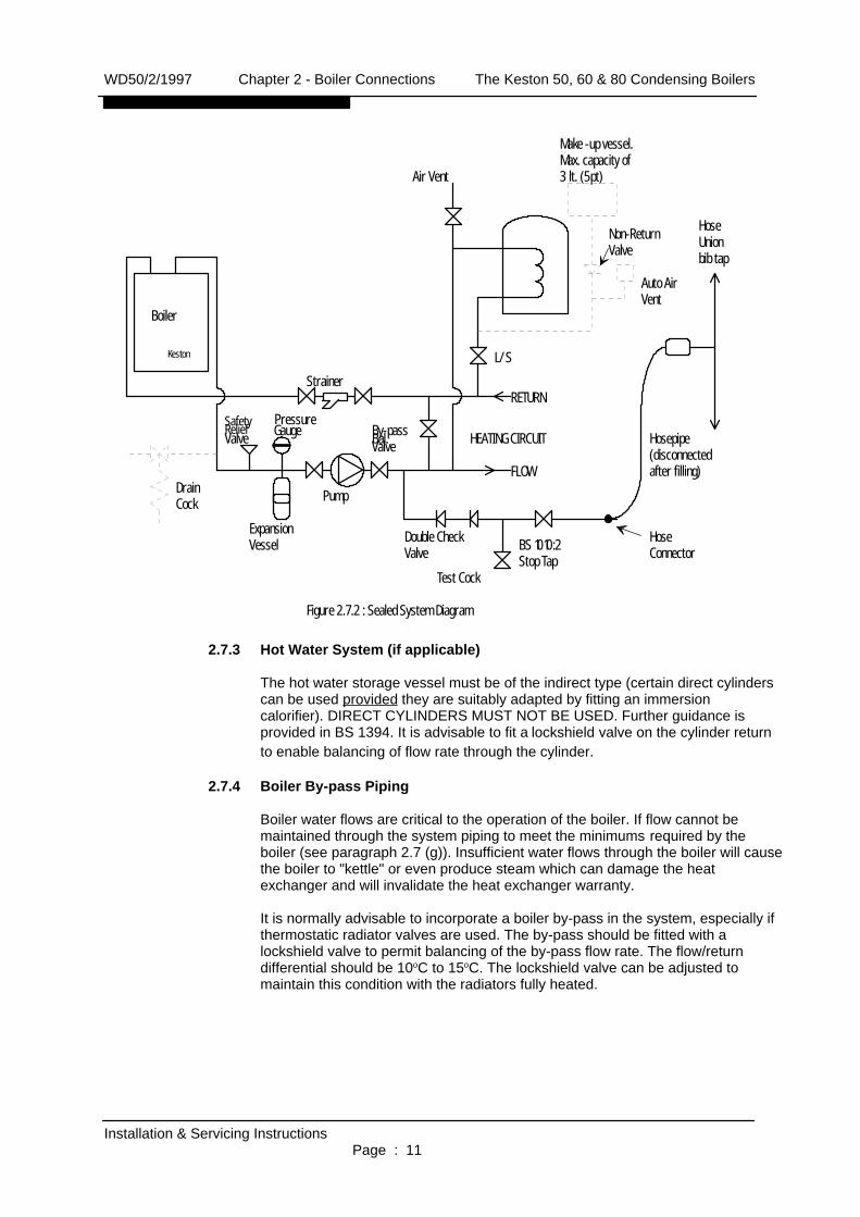
2.7.3 Hot Water System (if applicable)
The hot water storage vessel must be of the indirect type (certain direct cylinderscan be used provided they are suitably adapted by fitting an immersion calorifier). DIRECT CYLINDERS MUST NOT BE USED. Further guidance isprovided in BS 1394. It is advisable to fit a lockshield valve on the cylinder returnto enable balancing of flow rate through the cylinder.
2.7.4 Boiler By-pass Piping
Boiler water flows are critical to the operation of the boiler. If flow cannot bemaintained through the system piping to meet the minimums required by theboiler (see paragraph 2.7 (g)). Insufficient water flows through the boiler will causethe boiler to "kettle" or even produce steam which can damage the heatexchanger and will invalidate the heat exchanger warranty.
It is normally advisable to incorporate a boiler by-pass in the system, especially ifthermostatic radiator valves are used. The by-pass should be fitted with alockshield valve to permit balancing of the by-pass flow rate. The flow/returndifferential should be 10oC to 15oC. The lockshield valve can be adjusted tomaintain this condition with the radiators fully heated.
WD50/2/1997 Chapter 2 - Boiler Connections The Keston 50, 60 & 80 Condensing Boilers
Installation & Servicing InstructionsPage : 11
Valve
Boiler
Figure 2.7.2 : Sealed System Diagram
Keston
PressureGauge
ExpansionVessel Double Check
Valve
Pump
Air Vent
Make -up vessel.Max. capacity of3 lt. (5pt)
Non-ReturnValve
Auto AirVent
HoseUnionbib tap
Hosepipe(disconnectedafter filling)
HoseConnectorBS 1010:2
Stop TapTest Cock
DrainCock
HEATING CIRCUIT
RETURN
FLOW
Strainer
SafetyRelief By-passBal.Valve
L/S

2.7.5 Air Elimination
In the initial charge of water to the boiler system and in all subsequent additionsof water to the system some air will be dissolved in the water. As the water isheated the air is driven out of the solution and will collect in high spots in thesystem. These air bubbles can interfere with pumping and heat transfer andmust be eliminated.Installation of air bleed valves at the high spot(s) in the system will allow for airelimination when filling the system and will allow re-venting in a day or so after allair has been driven out of solution.Installation of an automatic air vent will ensure that any air, even minute amounts, which subsequently enters the system will be automatically removed.
2.7.6 Strainers
Debris in the heating systemcan cause noise if it enters theheat exchanger. Fitting of aY-strainer ahead of thecirculating pump will trap anydebris left in the system and will protect the pump fromdamage.
2.7.7 Pump Selection
The Keston boilers have lowwater content heat exchangerswith a high resistance to flow,when compared with cast ironheat exchanger boilers. As aresult selection of the correctpump is essential in order toavoid localised boiling withinthe heat exchanger. Theselected pump must becapable of maintaining therequired flow rate for the boileragainst the pressure lossescontributed by the boiler andthe rest of the system.
Refer to the pressure loss/flowrate Table 2.7.7 to determinethe pressure loss from theboilers. Add this to thepressure loss caused by therest of the system and select apump capable of meeting theflow rate required at the totalpressure loss generated by theboiler and the rest of thesystem. The selected pumpmust comply with BS 1394.
WD50/2/1997 Chapter 2 - Boiler Connections The Keston 50, 60 & 80 Condensing Boilers
Installation & Servicing InstructionsPage : 12
Y-Strainer willcollect any loosedebris in the piping.
Figure 2.7.6 Strainers
Figure 2.7.7 : Pressure Loss Graph
5 10 15 20 25 30
0.5
1.0
1.5
2.0
2.5
3.0
Water Flow - L/min
Pres
sure
Loss
- m
3.5
4.0
4.5
35
Keston 50Keston 60
Keston 80
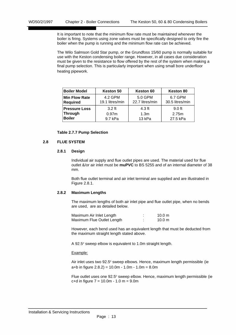
It is important to note that the minimum flow rate must be maintained whenever the boiler is firing. Systems using zone valves must be specifically designed to only fire theboiler when the pump is running and the minimum flow rate can be achieved.
The Wilo Salmson Gold Star pump, or the Grundfoss 15/60 pump is normally suitable foruse with the Keston condensing boiler range. However, in all cases due considerationmust be given to the resistance to flow offered by the rest of the system when making afinal pump selection. This is particularly important when using small bore underfloorheating pipework.
Table 2.7.7 Pump Selection
2.8 FLUE SYSTEM
2.8.1 Design
Individual air supply and flue outlet pipes are used. The material used for flueoutlet &/or air inlet must be muPVC to BS 5255 and of an internal diameter of 38mm.
Both flue outlet terminal and air inlet terminal are supplied and are illustrated inFigure 2.8.1.
2.8.2 Maximum Lengths
The maximum lengths of both air inlet pipe and flue outlet pipe, when no bendsare used, are as detailed below.
Maximum Air Inlet Length : 10.0 mMaximum Flue Outlet Length : 10.0 m
However, each bend used has an equivalent length that must be deducted fromthe maximum straight length stated above.
A 92.5o sweep elbow is equivalent to 1.0m straight length.
Example:
Air inlet uses two 92.5o sweep elbows. Hence, maximum length permissible (iea+b in figure 2.8.2) = 10.0m - 1.0m - 1.0m = 8.0m
Flue outlet uses one 92.5o sweep elbow. Hence, maximum length permissible (iec+d in figure 7 = 10.0m - 1.0 m = 9.0m
WD50/2/1997 Chapter 2 - Boiler Connections The Keston 50, 60 & 80 Condensing Boilers
Installation & Servicing InstructionsPage : 13
9.0 ft2.75m
27.5 kPa
4.3 ft1.3m
13 kPa
3.2 ft0.97m
9.7 kPa
Pressure LossThroughBoiler
6.7 GPM30.5 litres/min
5.0 GPM22.7 litres/min
4.2 GPM19.1 litres/min
Min Flow RateRequired
Keston 80Keston 60Keston 50Boiler Model

2.8.3 Slope
'Horizontal' flue outlet pipeworkMUST slope at least 2.5degrees (45 mm per metrerun) downwards towards theboiler. Pipework can bevertical. Only swept elbows canbe used.Air inlet pipework can be trulyhorizontal or vertical, or sloping in a downward directiontowards the boiler but in thiscase rain, etc, must beprevented from entering thepipe. There must be notroughs in any of thepipework, whether it be airinlet or flue outlet. If a 45 mm per meter slope is notpossible, contact Keston Boilers Technical Department for further guidance.
Due the low temperature ofthe flue gases further condensatewill form within the flue system. Drainpoints, with suitable traps, musttherefore be incorporated within theflue system at the base of verticalflue sections in excess of 2m. Theseadditional condensate drains mustbe run to discharge as detailed insection 2.11. Such drain points canbe formed using standard muPVCfittings. Refer to the example inFigure 2.8.3.
2.8.4 Terminations
It is not advisable to terminate airintake or flue within a car port area.
Air inlet terminals must be facing upwards and positioned to ensure only fresh airis drawn into the boiler directly from outside the property.The flue outlet terminal is designed to face outwards but can, if desired, beadapted to face in any direction BUT must not be directed in the region of the airinlet.The two terminals are subject to the requirements of BS 5440 Pt 1 for clearancesfrom features of the building although some can be decreased to the valuesindicated. If either the air inlet or the flue outlet terminate at a height of less than2m (6ft) above ground level the termination must be protected by a suitableguard. The K4 terminal guard, manufactured by Tower Flue Components Ltd, issuitable for this purpose and can be obtained from Keston Boilers.The Keston Condensing Boiler, as with any condensing boiler, will generate acondensate "plume" from the flue terminal in all weather conditions.
Consideration must therefore be given to the effect of this "plume" when selecting a location for the flue terminal.
WD50/2/1997 Chapter 2 - Boiler Connections The Keston 50, 60 & 80 Condensing Boilers
Installation & Servicing InstructionsPage : 14
FLUEAIR
cd
ab
Figure 2.8.2 : Flue & Air Maximum Length Example
Keston
6 in min.
Figure 2.8.3 :Flue Condensate DrainPoint Example
40mm Tee FittingTo Boiler
To Te
rmina
l

It is advisable for horizontal flue terminals to place a 45o elbow at the end of theflue to direct the condensate plume up and away from the property.
Table 2.8.4 Minimum Flue Terminations & Air Inlet Dimensions
2.8.5 Clearances From Wall
Flue outlet and air inlet termination must be at least 60 mm and 95 mmrespectively from the wall face.
2.8.6 Distance Between Flue Outlet & Air Inlet
There is no maximum - the terminations can be on opposite sides of the dwellingif desired.
WD50/2/1997 Chapter 2 - Boiler Connections The Keston 50, 60 & 80 Condensing Boilers
Installation & Servicing InstructionsPage : 15
300300L Horizontally from terminal on same wall.1.51.5K Vertically from terminal on same wall.1001.2J From opening in a car port.1.21.2I From terminal facing a terminal.100600H From surface facing a terminal100300G Above ground or balcony or roof.50600F From internal or external corner.5075E From vertical drain or soil pipes.50200D Below balconies.50300C Below eaves.7575B Below gutters, soil pipes, drain pipes.50300A Below openable window, air brick, etc.
AirInlet
FlueTerminal
Dimensions (mm)
Flue Outlet Terminal
Air Intake TerminalFigure 2.8.1 : Terminals
O43
65
3670
170
O43
O67

A minimum clearance of at least 350 mm must be left between the terminations.2.8.7 General Installations
All parts of the system must be constructed in accordance with BS 5440 Part 1,except where specifically mentioned in these instructions.All pipework must be adequately supported.All joints other than push-on or plastic compression connectors must be madeand sealed with solvent cement suitable for muPVC pipes and conforming to BS6209: 1982.External wall faces and any internal faces of cavity walls must be made good.
2.9 AIR SUPPLY
The Keston is a room sealed appliance and therefore does not require purpose providedventilation for combustion air.
2.10 COMPARTMENT INSTALLATION
Where the appliance is installed in a cupboard or compartment, no air vents are required. The boiler will run sufficiently cool without ventilation.
2.11 CONDENSATE DRAINAGE
Being a condensing boiler, the Keston is fitted with a condensate trap at the base of theheat exchanger and flue assembly, with facility to connect to a drain point underneath theappliance.
Use only plastic piping and do not reduce below 22mm internal diameter within thedwelling. Condensate should preferably be drained into the house sanitary waste systemor, alternatively, the rainwater system. Termination of the pipe must be either at a branchor stack internal to the house, or externally at an open gully. Alternatively, discharge into a purpose made condensate soakaway can be considered. Existing or purpose builtdrains must use suitable corrosion resistant material as condensate is mildly acidic.
A minimum slope downwards towards the drain of 2.5o (45mm fall in 1m) is essential.Freezing of the termination and pipework must be prevented. Any drainage pipes outsidethe house must be at least 32 mm inside diameter.
Further guidance is given in the British Gas Publication 'Guidance Notes for theInstallation of Domestic Gas Condensing Boilers'.
2.12 RADIANT FLOOR HEATING
This type of heat distribution creates an exceptionally evenly heated environment andsince it is hidden beneath the finished flooring does not interfere with furniture placement. The homeowner has complete freedom to decorate without having to contend with any heating equipment visible in the homes interior. The low operatingtemperatures of this type of system lead to very good operating efficiencies. In fact, under floor heating can produce in excess of 95% operating efficiency from a Keston condensing boiler. Water temperatures in radiant floor heating systems must be keptrelatively low, generally under 48oC, so that surfaces do not become uncomfortably warmto the touch. If radiant heating is only one application for a multi-zone system which alsorequires higher delivery water temperatures for other zones (i.e. water heating, skirtingheaters etc.) then the radiant floor zone temperature will need to be controlled separatelyfrom the boiler.
If radiant floor heating is the only application of the boiler, the boilers temperature limitscan be lowered accordingly by introducing an external thermostat control mounted on thereturn pipework into the boiler. This thermostat can then be used to interrupt power
WD50/2/1997 Chapter 2 - Boiler Connections The Keston 50, 60 & 80 Condensing Boilers
Installation & Servicing InstructionsPage : 16

supply to the boiler when the required temperature is reached. Mixing valves are alsoavailable which will mix return water from the system with boiler output water to dilute thetemperature of water transmitted to the distribution system. Mixing valves may createproblems with low flow and high temperatures through the boiler unless care is taken todesign a system which will provide proper flows and will fully load the boiler. Keeping theboiler's temperature high will prevent the boiler from operating at peak efficiencies.Systems which maintain boiler temperatures in this way should be avoided.
If only a portion of the boiler's available output is to be used for radiant floor heating athermal storage tank will improve the boiler's operation and give adequate control oftemperature for the distribution system. By heating water to be distributed to the radiantfloor zone to the proper temperature in an indirect-fired water heater, full load conditionswill be available to the boiler because the heat exchanger in the tank can be sized tomatch the boiler's output. The tank's thermostat can be set at the optimum operatingtemperature needed by the distribution system and short-cycling of the boiler will beprevented. In such insulations it is advisable to calibrate the thermal store's operatingthermostat to become the controlling thermostat of the boiler, ie the thermal storeoperating thermostat is always activated to shut off the boiler before the boilers ownthermostat is activated. An insulated thermal storage tank without the heat exchanger mayalso be used.
2.13 LOW WATER VOLUME BOILER VS. CAST IRON BOILER
Because of their high water content and mass of metal, cast iron and steel boilers are lessresponsive but somewhat more forgiving of design errors. Short-cycling of the burner on the temperature limit control is less pronounced, though no less detrimental tooperation, because the boiler itself will absorb and radiate a significant amount of heat.Low water volume boilers respond more quickly to a call for heat, can be made morecompact and lightweight, but must have adequate heat delivery systems to avoidshort-cycling of the burner on the temperature limit control. The heat delivery system'soutput must be equal to or greater than the boiler's output to fully load the boiler orshort-cycling will occur.
Likewise, pumping rates of water through low water volume boilers must be maintained sothat water is moved through the boiler fast enough so as not to reach boilingtemperatures. The slower the water moves through the boiler the more heat it will absorband the higher the temperatures will rise. Consequently, the pump selected must beadequate to maintain that critical flow of water.
2.14 DETERMINE RADIATION NEEDED ROOM-BY-ROOM
A radiator or convector's ability to deliver heat is related to the water temperature and therate of delivery to the unit. Most systems in the past have been rated at about 80oC.Higher efficiencies can be gained from a condensing boiler if ratings published at lowertemperatures are used. However, this is not imperative. With normal 80oC ratings used acondensing boiler will still deliver significantly higher efficencies than a non-condensingboiler. Lower water temperatures in the system tend to increase the efficiency of the boiler and will help assure that the boiler is subjected to a sufficient load to avoidshort-cycling.
The Keston boilers are capable of temperatures of up to 80oC but the higher thetemperature of the return water, the lower the efficiency of the system. This is true of allboilers, though all non-condensing boiler must be kept at higher temperatures to avoidcondensation in the boiler which destroys such boilers quickly. Materials used in theKeston are made to withstand the condensates corrosive nature.
WD50/2/1997 Chapter 2 - Boiler Connections The Keston 50, 60 & 80 Condensing Boilers
Installation & Servicing InstructionsPage : 17

3. INSTALLATION OF THE BOILER
Read Chapter 2 - Boiler Location and decide upon the position of the boiler.
Installation of the boiler is straightforward but consideration must be given to access to allow flueand air pipes to be pushed through walls and ceilings. The order in which the components areinstalled will depend upon particular site conditions, but in general it will be easiest and mostaccurate to install the boiler and then build up the flue outlet and air inlet pipes to the terminal - this is the sequence described.
3.1 WALL MOUNTING BRACKET
a Place the bracket on the wallhorizontally with the pre-drilledholes at the bottom.
b Drill through the centre hole of the bracket, plug the hole and fix in position.
c Using a spirit level make surethe bracket is completely leveland mark the position of theother screw holes.
d Remove the bracket and drill theholes in the positions marked.Plug these holes.
e Screw the bracket to the wallusing screws of an appropriatesize for the wall type (No. 12 x 2inch wood screws normallysuffice).
f Mark the bottom fixing hole anddrill for a No 8 x 1 inch woodscrew. Insert plug.
3.2 MOUNTING THE BOILER
a Lift and locate the upper rear lip on the boiler to the boiler wall bracket.
b Move the boiler sideways to centralise the boiler on the bracket.
c Screw in the lower fixing screw.
3.3 ASSEMBLY PRACTICE
Remove all plastic debris and burrs when installing air intake piping. Plastic filings caused by cutting muPVC pipe must not be allowed to be drawn into the filter orcombustion air blower. Prevent dust entering the air intake when cutting on building sites.Blower failure which is determined to be caused by plastic filings or other debris will not be covered by guarantee.
WD50/2/1997 Chapter 3 : Installation The Keston 50, 60 & 80 Condensing Boilers
Installation & Servicing InstructionsPage : 18
All dimensions in mm.
Figure 3.1 Wall Mounting Fixing Locations
110
285
250

Combustion air filters are fitted to the Keston condensing boilers as standard. Thisfilter must be examined at least once every year, and more often in particularlydusty and dirty areas.
The combustion air filter will prevent plugging of the burner caused by dirt being trapped in the burner's outer mesh. The filter element supplied with the boiler is obtainable fromKeston Boilers or its distributors.
3.4 INSTALLING FLUE AND AIR PIPES
Remember the flue pipe must slope downwards back towards the boiler and this is bestachieved using 92.5o bends.
a From the two connections on the boiler, mark the positions of the two holes forthe flue and air pipes on the wall(s) or ceiling. To allow access to drill the holes itmay be necessary to temporarily remove the boiler. If the boiler stays put then it is imperative that the front panel and top access plate are replaced and the twoplastic pipes capped off whilst drilling. Under no circumstances must debris fromthe wall or cut pipes be allowed to enter the appliance or the plastic pipework.
b Drill the two holes in the wall/ceiling, preferably using a core drill.
3.4.1 Diameter of holes.
i) Allowance must be made forsocketed lengths if these areto be passed through theholes :
du = unsocketteddiameter
= 43 mmds = socketed
diameter= 50 mm
ii) For 'horizontal' runs of fluepipe the holes must either beoversized or cut at a 5o slope(the latter may be difficult onlong holes).
3.4.2 Oversizing
For every 1m length of run, L, the minimum diameter of the horizontal hole, D, must be du + 10 mm or ds + 10 mm respectively, assuming the pipe touches thewall at points T otherwise D will have to be increased by clearance from T. SeeSection 3.4.3 - Examples.
3.4.3 Examples
a. Wall Depth L = 750 mmUnsocketted pipe du = 43 mmDiameter hole D = 43+{(750/1000)X10}
= 43+7.5= 50.5 mm
WD50/2/1997 Chapter 3 : Installation The Keston 50, 60 & 80 Condensing Boilers
Installation & Servicing InstructionsPage : 19
D
L
duT
dsFlue Pipe
T

b. Wall depth L = 2.3 mSocketed Pipe ds = 50 mmDiameter Hole D = 50+{2.3x10}
= 50+23= 73 mm
c. Measure, cut and check the air and flue pipes to pass to the exit from thewall(s) or ceiling.
Always thoroughly deburr all pipes and, most important, remove shavings fromwithin the pipe.
d. Assemble, using adhesive, the pipework from the boiler connections tothe exit from the first wall/ceiling (remount the boiler if removed). Whenpushing pipe through walls, ensure grit and dust is not allowed to enterthe pipe.Ensure pipes are fully engaged intosockets.Connect the condensate drainagesystem and fill the condensate trap bypouring water down the boiler fluespigot ( See Section 3.5 CondensateDrainage).Make the final connection of flue and air pipe to the boiler using pushon, or plastic compressioncouplings. Ensure that the connectorsare set vertically otherwise leakage ofcondensate may occur which will corrode the casing. Do not useadhesive on the 'push on' end of the connecting couplings.
e. Using the same methods drill any further holes (always covering existingpipework), cut and assemble the pipework.
f. From outside, complete the two terminations - See Section 2.8 FlueSystem and make good all holes.
g. Support any pipes whose route could be displaced either of its ownaccord or by accident. Any horizontal run over 1m or vertical runs of anylength must always be supported.
h. Check all connections for security and re-seal any joints using soventcement where soundness may be in doubt.Note: It is equally important to seal the air inlet with solvent cement as
the flue outlet pipe joints.
3.5 CONDENSATE DRAINAGE
Connect the condensate drainage system to the boiler. It is advisable to use a detachable fitting at connection to the boiler to enable easy removal for servicing.
Fill the condensate trap by pouring water into the boiler flue spigot until water is seen toflow freely from the condensate drainage system. Make the final connection of flue pipe tothe boiler.
Details are provided in Chapter 2 - Section 2.11 Condensate DrainageConnection : 22 mm plastic pipe.
WD50/2/1997 Chapter 3 : Installation The Keston 50, 60 & 80 Condensing Boilers
Installation & Servicing InstructionsPage : 20
F A
Fully Engaged
Adhesive

3.6 WATER SYSTEM
Connect the flow and return pipework to the boiler. Ensure a detachable coupling is usedat connection to the boiler (ie compression fitting) to enable heat exchanger removal ifrequired. Details of system requirements are given in Chapter 2 - Section 2.7 WaterSystems.
Connections : 28mm copper
3.7 GAS SUPPLY
Connect the gas supply to the appliance. Details of gas supply requirements are given inChapter 2 - Section 2.6 Gas Supply.
Connections : 0.5 inch BSP male. (15mm connection to gas cock).
3.8 ELECTRICAL SUPPLY
The entry point for the electrical supply cable is in the base of the appliance (see Section2.2 Service Connections fig. 2.1.2) via a cordgrip bush. Feed the cable through this bushand route inside the cabinet to the connection strip located to the front bottom right of thecabinet.
1. The electrical supply must be as specified in Chapter 2 - Section 2.4 ElectricalSupply.
WARNING : THIS APPLIANCE MUST BE EARTHED.
2. All external controls and wiring must be suitable for mains voltage. Wiring shouldbe in 3 core PVC insulated cable not less than 24/0.2 mm (0.75mm) to BS 6500Table 16.
3. The supply connection must be via a 5 amp fused double pole switch, servingonly the boiler and system controls. (Refer to Chapter 2 - Section 2.4 ElectricalSupply).
4. Securely tighten the terminal screws and route the cable through the re-openablecable clips. Ensure all cables are secured and that the cord grip bush is tightenedto securely grip the main cable at entry to the cabinet.
The mains cable must be connected to the terminals as follows:-
N - Blue wire (Neutral)L - Brown wire (Live)
- Yellow/Green Wire (Earth)
Ensure connection is made such that if the cable slips in its anchorage the currentcarrying conductors become taut before the earthing conductor.
3.9 EXCHANGING A BOILER
Before removing an existing boiler add Fernox Supafloc , or equivalent cleaning agent, in accordance with the manufacturers instructions. Open all radiator valves and fire theboiler. When the system is fully heated, shut off the gas supply and drain down the centralheating system.
WD50/2/1997 Chapter 3 : Installation The Keston 50, 60 & 80 Condensing Boilers
Installation & Servicing InstructionsPage : 21

ImportantThe Keston condensing boiler contains components which could be damaged orblocked by grease, dirt or solder etc. It is essential that sludge or scale is removedfrom an existing system.
Connect the new boiler as instructed in this manual and fit in accordance with Sections3.1 to 3.8
For sealed systems, fill to a pressure of about 2.7 bar. Check the complete system forwater soundness. If leaks need to be rectified using flux or solder the system must beflushed cold again before proceeding.
Reduce the pressure to the Initial System Design Pressure for sealed systems, ifapplicable. Vent the system.
Gas SupplyThe complete gas installation up to the boiler service cock must be checked forsoundness. BS 6891.
Electrical InstallationCarry out preliminary electrical safety checks, i.e. Earth continuity, Polarity, Resistance to Earth, Short Circuit using a suitable test meter.
Initial FiringChecking The Gas Pressure At The Burner Pressure Test NippleThe gas burner pressure must be checked at the burner pressure test nipple (Figure 5.7.3item 54). Full details of this procedureare given in Section 4.7 Checking TheGas Pressure.
The gas pressure setting is factoryadjusted to within the required rangeand should not normally needre-adjustment. If the reading is incorrectthen check such factors as soundness ofthe air and flue pipe joints, pressuresensible joints and the gas inlet pressure(20 mbar required). If all joints are soundand the gas inlet pressure is satisfactoryset the gas pressure to the requiredpressure.
WD50/2/1997 Chapter 3 : Installation The Keston 50, 60 & 80 Condensing Boilers
Installation & Servicing InstructionsPage : 22
Burner pressureAdjustment
Burner pressuretest nipple.
GAS VALVE

4. COMMISSIONING OF THE BOILER
Important:This condensing boiler contains components which could be damaged or blocked by grease, dirt,solder etc., from the water system. The following commissioning procedures must be followedprecisely.
4.1 INITIAL FLUSHING
All waterways within the Keston are either copper or high alloy stainless steel. As a resultstandard water treatment chemicals for conventional central heating boilers are suitable.In any event reference must be made to BS 7593 : Treatment Of Water In Hot WaterCentral Heating Systems.
a. Disconnect the boiler from the system at the flow and return connections andtemporarily link the flow and return pipes on the system.
b. Flush the entire system until clean water is discharged, free from dirt, flux, solderetc. The use of a flushing chemical is recommended, e.g. Fernox Supafloc.
Sludge and scale must be removed from an existing system.
c. Connect the system to the boiler and fill in accordance with Section 2.7 - WaterSystems. At this stage, for sealed systems, fill to a pressure of about 2.7 bar.
d. Check the complete system for water soundness. If leaks need to be rectifiedusing flux and solder, the system must be flushed cold again before proceeding.
e. Reduce the pressure to the Initial System Design Pressure for sealed systems, ifapplicable. Vent the system
4.2 GAS SUPPLY
The complete gas installation up to the boiler service cock must be checked forsoundness. BS 6891.
4.3 ELECTRICAL INSTALLATION
Carry out preliminary electrical safety checks, i.e. Earth continuity, Polarity, Resistance toEarth, Short Circuit using a suitable test meter.
4.4 LP GAS CONVERSION
All Keston condensing boilers are built and shipped as natural gas fired units. Fieldconversion kits are available to convert Keston condensing boilers to use LPG. Suitableinstructions are supplied with the LPG field conversion kits.
4.5 INITIAL FIRING
ImportantChecking the gas pressure to the pre-mix burner requires a special procedure, outlinedbelow, which must be carried out.
a. Purge the gas supply in accordance with BS 6891.
b. Turn the gas service cock OFF.
c. Loosen the screw in the burner pressure test point (Figure 5.7.3 item 106A) onthe gas valve and attach a suitable gauge.
WD50/0/1996 Chapter 4 : Commissioning The Keston 50, 60 & 80 Condensing Boilers
Installation & Servicing InstructionsPage : 23

d. Turn on the electrical supply, setting any external controls to call for heat.
e. ON/OFF switch - select 'ON'. The amber 'run' light will illuminate on the ON/OFFswitch, the red 'lockout' light will illuminate, the blower and pump will start and,after about 15 seconds, a spark will attempt to light gas at the burner. With thegas service cock off, the boiler will go to lockout - red light illuminated, but theblower and pump will continue to run. At intervals of approximately 1 minute theboiler will make two further attempts to fire. After the final attempt the blower willrun for a further 20 seconds before shutting down.
f. Vent the water system.Important:The Keston heat exchanger consists of a single coil which can trap an air pocket.Great care must be taken to ensure that water flow has been established throughthe heat exchanger and thus ensuring no air pockets remain in the heatexchanger and pipe work. Firing the boiler while an air pocket exists in the heatexchanger could damage it.
g. Note the reading on the pressure gauge caused by the suction of the blower. Thisshould be approximately minus 12 mbar for the Keston 80, minus 26 mbar for theKeston 60 and minus 32mbar for the Keston 50. If it is not, check the system asfollows:
If the negative pressure exceeds the required figure, then it suggeststhat there is a possible restriction in the air inlet pipework.
If the negative pressure is less than required figure, then it suggeststhat there is a possible restriction in the flue outlet pipework. Note theexact reading.
h. Turn the gas service cock to ON.
i. Turn off the electricity supply, wait 10 seconds and turn back on. The boiler willagain go through its ignition sequence but this time the main burner will light,provided all air has been purged from the gas supply to the boiler. When theburner is lit and the boiler is operating normally the the green (run) lamp, theupper lamp adjacent to the flame symbol, will also be illuminated indicatingsuccessful ignition.(If it does not, air is indicated - turn off and repeat theprocedure).
If this does not occur, the green (run) lamp, the upper lamp adjacent to the flamesymbol, will be extinguished and, at approximately 1 minute intervals, theelectronic ignition system will make two further attempts to light the burner.
If the ignition is successful and the boiler is operating normally, the green (run)lamp, the upper lamp adjacent to the flame symbol, and the red (lockout) lamp willbe illuminated simultaneously.
If, after three automatic attempts, the boiler still fails to ignite, the green (run)lamp, the upper lamp adjacent to the flame symbol, will be extinguished and thered (lockout) lamp will remain illuminated.
If, after five manual attempts (to allow for purging of any air in the gas line), theboiler still fails to ignite (indicated by the red (lockout) lamp) refer to Section 5.2 -Fault Finding Flow Chart.
j. Check for gas soundness between the gas service cock and connection to theburner manifold.
WD50/0/1996 Chapter 4 : Commissioning The Keston 50, 60 & 80 Condensing Boilers
Installation & Servicing InstructionsPage : 24

4.6 HOT FLUSHING
a. Allow the system to heat up,checking for water soundness.
b. Follow instructions provided withthe cleaning agent, ie FernoxSupafloc. Turn off the boiler andflush the water system while stillhot. Thoroughly flush the systemwith clear water.
c. Refill the system using a quality water treatment such as Fernox MB1 or FernoxSuper Concentrate. If aluminium radiators are used then Fernox Copal should beused. For sealed systems, fill to the required Initial Design Pressure.
4.7 CHECKING THE GAS PRESSURE
With the boiler running measure the burner pressure at the burner pressure test nipple.
The gas setting is factory adjusted to within the required range and should not normallyneed re-adjustment unless the unit has also been converted to LPG as part of theinstallation. If the reading is incorrect then check such factors as soundness of the air andflue pipe joints and the gas inlet pressure (20 mbar required). If all joints are sound andthe gas inlet pressure is satisfactory remove the brass dust cap covering the burnerpressure adjustment screw on the gas valve (See fig. 4.7). Set the gas pressure to therequired value as stated in table 1.4 by turning the exposed burner pressure adjustmentscrew (clockwise will increase burner pressure, anti-clockwise will decrease burnerpressure). Replace the brass dust cap to cover the burner pressure adjustment screw.
4.8 TIMING THE GAS METER - NATURAL GAS
Table 4.8 Meter Timings
After the boiler has been started, and with no other appliances using gas, time the gasmeter to be certain that the unit is running at the proper gas input. Determine the cubicfeet of gas passing through the meter and determine the input in Btu per hour. Input mustbe within plus or minus 5% of the rated input.
Time, in seconds, the time taken to pass 2 cubic feet of gas through the meter (ie onerevolution of a 2 cu ft dial) or 0.1 cubic metres if the meter is of the new metric digital type.Refer to table 4.8 to determine the input to the boiler and the time required for 2 ft3 (or
WD50/0/1996 Chapter 4 : Commissioning The Keston 50, 60 & 80 Condensing Boilers
Installation & Servicing InstructionsPage : 25
Burner pressureAdjustment
Burner pressuretest nipple.
GAS VALVEFig 4.7
1011 btu/h per ft3NB: 152.3686.384,300Keston 80203.9115.563,018Keston 60236.2133.854,400Keston 50
Seconds For 0.1 m3
Of Natural GasSeconds For 2 ft3
Of Natural GasBtu/h Input RequiredModel

0.1m3) of natural gas. Adjust the gas valve screw clockwise to increase the input (speedup the meter) or anticlockwise to decrease the input(slow down the meter) accordingly.
4.9 HANDING OVER TO THE USER
It is important to fully explain the following :a. Procedure to light and turn off the boiler, including isolation of the electrical supply
if necessary.b. The function of the lockout feature must be explained :
If the red light only is illuminated for more than four minutes, this means that theboiler has failed to light. Turn off the electrical supply and wait 20 seconds. TurnON again and wait.i) If lockout recurs immediately then the gas supply should be checked as
ON, otherwise consult a Service Engineer.ii) If it is not possible to relight, the boiler must be isolated and a Service
Engineer called in to rectify the fault.c. Advise that a reduction in the water pressure reading on the gauge for sealed
systems indicates a leak which should be rectified before further use.d. Advise that the appliance should be serviced by a competent person at least once
a year.e. Advise on frost precautions.f. Hand over User Instructions.
WD50/0/1996 Chapter 4 : Commissioning The Keston 50, 60 & 80 Condensing Boilers
Installation & Servicing InstructionsPage : 26

5. FAULT FINDING
5.1 ELECTRICAL CONTROL SEQUENCE
When the external controls are calling for heat, power will be fed to the boiler connectionstrip at terminals L (Live) and N (Neutral). If the ON/OFF switch is also in the ON positionthe boiler ON lamp (amber) will be illuminated. Provided all temperature thermostats andpressure switches are closed, power will be fed to pin 2 on the control box, initiating thefollowing sequence.
(1) The boiler lockout lamp (red) will be illuminated
(2) The fan will start.
(3) When the fan reaches running speed, the Air Pressure switch, normally open, willclose which will start the ignition sequence.
(4) After a pre-purge period of about 15 seconds, the gas valve will open to allow gasto mix with the air at the suction side of the fan and the ignition spark will occur atthe main burner.
(5) When the burner ignites, the flame is detected by the control box through thecombined flame sensor/ignitor and the ignition spark is stopped. Both the lockoutlamp (red) and the boiler run lamp (green), the upper lamp adjacent to the flamesymbol, will be illuminated. The boiler is now in its normal run condition.
(6) The burner will continue to operate until the gas valve interrupts the gas supply.The gas valve will be closed by the control box if power is interrupted to the boilerby any external control or the boiler thermostat. If an interruption to the gas supplycauses loss of the flame the control box with pause for approximately 10 secondsand then attempt to re-ignite the unit. If this attempt fails, ie due to lack of gassupply, the boiler will make two further attempts to ignite at intervals ofapproximately 1 minute and will then go into a lockout state (red lamp illuminatedonly). Once gas supply has been resumed the boiler can be reset by turning theboiler off and then on again via the on/off switch on the boiler control panel.
(7) The boiler can also be shut down by any of the flow limit, flow overheat and theflue overheat thermostats, gas low pressure switch and by the low water pressureswitch.
In such an event the green (run) lamp, the upper lamp adjacent to the flamesymbol, will be extinguished and only the red (lockout) lamp will be illuminated.
Any failure of the boiler to sequence in the above manner should be investigated using thefollowing trouble shooting flow diagram.
Before attempting any electrical fault finding, always carry out preliminary electrical systemchecks. On completion of any service/fault finding task which has required the breakingand remaking of electrical connections, the checks, earth continuity, polarity, short circuit,resistance to earth must be repeated.
WD50/2/1997 Chapter 5 : Fault Finding The Keston 50, 60 & 80 Condensing Boilers
Installation & Servicing InstructionsPage : 27
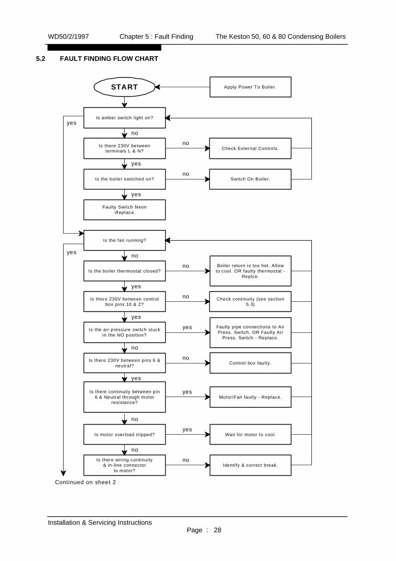
5.2 FAULT FINDING FLOW CHART
WD50/2/1997 Chapter 5 : Fault Finding The Keston 50, 60 & 80 Condensing Boilers
Installation & Servicing InstructionsPage : 28
yes
no
yes
yes
no
no
no
yes
yes
no
yes
no
no
yes
Continued on sheet 2
no
yes
yes
no
yes
no
no
START
Is amber switch light on?
Is there 230V betweenterminals L & N?
Is the boi ler switched on?
Faulty Switch Neon-Replace.
Switch On Boiler.
Check External Controls.
Apply Power To Boi ler.
Is the boi ler thermostat closed?
Is there 230V between controlbox pins 10 & 2?
Is the air pressure switch stuckin the NO position?
Is there 230V between pins 6 &neutral?
Is there continuity between pin6 & Neutral through motor
resistance?
Is the fan running?
Is motor overload tr ipped?
Is there wiring continuity& in-line connector
to motor?
Boiler return is too hot. Allowto cool. OR faulty thermostat -
Replce.
Check continuity (see section5.3)
Faulty pipe connections to AirPress. Switch. OR Faulty Air
Press. Switch - Replace.
Control box faulty.
Motor/Fan faulty - Replace.
Wait for motor to cool.
Identi fy & correct break.

WD50/2/1997 Chapter 5 : Fault Finding The Keston 50, 60 & 80 Condensing Boilers
Installation & Servicing InstructionsPage : 29
From sheet 3
yes
yes
no
Continued on sheet 3
no
yes
no
yes
yes
yes
yes
no
yes
no
no
no
no
yes
no
yes
no
Continued from sheet 1
yesDoes ignition sequence start?
Is lockout light on?
Has the Air Press. Switchchanged over?
Are tubes and connections tothe Air Press. Switch sound?
Is the air press. across the AirPress. Switch more than 4 in
water?
Is the air fi lter dirty or the airinlet, exhaust or condensate
pipe blocked?
Is the Burner blocked
Fan faulty - change
Is the gas flow rate to the boiler correctfor the gas type in use (ie LPG or Nat.
Gas)?
Is gas supply pressure at gasvalve correct?
Is gas burner pressure perspecification (Section 4.7)?
Is gas valve openeing?
Check gas supply or turn ongas cock.
Replace gas ori fice.
Faulty gas valve - replace.
Switch off & if problem persistsreplace control box.
Blocked air fil ter - replaceOR
Faulty control box - replace
Correct tube connection
Faulty pressure switch -replace
Replace air fi lterOR
clear blockage
Clear blockage

WD50/2/1997 Chapter 5 : Fault Finding The Keston 50, 60 & 80 Condensing Boilers
Installation & Servicing InstructionsPage : 30
Continued on sheet 2
yes
no
no
no
yes
yes
yes
yes
no
yes
yes
no
yes
yes
no
no
no
Continued from Sheet 2
Is there 230V at valve
Is there 230V at Gas LowPress. Switch
Faulty Control Box - Replace.
Faulty Gas Valve - Replace.
Faulty Gas Low PressureSwitch - Replace
Is there a spark present?
Is the HT voltage present attop of ignito electrode?
Is the spark gap 4 mm?
Faulty Conrtrol Box - Replace.
Replace/Adjust Spark Plug.
Does the burner ignite?
Electrode Faulty - Replace.
Recheck gas output pressure.Check HT lead is securely
fixed. Clean or replace burner.
Does flame stop after 5 - 10seconds?
Is boi ler earthed correctly?
Are live and neutral supplylines crossed at terminals L &
N?
Faulty Control Box - Replace.
Earth Boiler.
Correct Wiring.

5.3 CONTINUITY CHECKING
WD50/2/1997 Chapter 5 : Fault Finding The Keston 50, 60 & 80 Condensing Boilers
Installation & Servicing InstructionsPage : 31
START
Is there 2 30 V a t te rm ina l L?
Is th ere 23 0V at the O N/O FFswit ch (bo th term in als )?
Is there 2 30 V at the bo ile rtherm os ta t (both term in als )?
Is there 2 30 V a t the f lowov erh eat the rmos tat (bo th
term in als )?
Is there 23 0V a t th e th erm alfus e l in k (b oth term ina ls )?
Is there 2 30 V a t th e f low h ighlim it the rmos tat (both
term in als )?
Is there 2 30 V at the waterpre ss . sw itch (b oth term ina ls )?
Is there 2 30 V at the f lu epro tec t io n the rmo sta t (b oth
term in als )?
Che ck ex te rna l cont ro ls .
Fau lty sw i tch - Re place.
Therm os ta t tri pp ed - reset ORfau l ty th erm os ta t - Rep la ce .
H ig h ca bin et tem pe ratu re -ch ec k a ll jo in ts for pro du cts
le akag e - R epl ac e therm a l fu se
H igh water te mpe ratu re O Rfau l ty th erm os ta t - Rep la ce .
Ch eck wate r le ve l h ead ertank /sys tem pressu re O R fau lty
sw i tch - Re pla ce
Therm os ta t tri pp ed - reset ORfau l ty th erm os ta t - Rep la ce .
yes
yes
yes
yes
yes
yes
yes
no
no
no
no
no
no
no
no
Is there 2 30 V a t the g as lo wpress . sw i tch (b oth term inals)?
Ch eck g as sup ply to bo ile r O Rfau l ty sw itch - R eplace.
no
yes
To check con t inu ity connec t one probe to a ne u tra land use the o th er probe to c heck fo r 230V .
B oiler is u p to te m pera tu re.Allow to cool O R p um p not
ru nn in g O R fa ul ty thermo stat -R eplace

5.4 FUNCTIONAL FLOW WIRING DIAGRAM
WD50/2/1997 Chapter 5 : Fault Finding The Keston 50, 60 & 80 Condensing Boilers
Installation & Servicing InstructionsPage : 32
ON/OFF Switch
Boiler
Flow Overheat
Thermal Fuse
Flow High Limit
Low Water
Flue Overheat
RAM-2EMC22
IGNITION CONTROL
Thermostat
Thermostat
Thermostat
Thermostat
Pressure Switch
5 21
4610
Lockout (Red)
Run(Green)Indicator
Gas Valve
Gas LowPressure
ON/OFF Switch
Blower
N
L
AirPressureSwitch
EMC Filter
EMC Filter
8
230V 50HzFuse 5A
Link
Switch
Indicator
HT

5.5 ELECTRICAL WIRING DIAGRAM
WD50/2/1997 Chapter 5 : Fault Finding The Keston 50, 60 & 80 Condensing Boilers
Installation & Servicing InstructionsPage : 33
IGNITION CONTROLRAM-2EMC22
13 12 11 10 9 8 7 6 5 4 3 2 1
1
2
4
3
5
7
6
8
10
9
11
12
N
LFILTER ON/OFF
SWITCH
GREENLAMP
FLUE OVERHEATTHERMOSTAT
WATER PRESSURESWITCH
FLOW HIGH LIMITTHERMOSTAT
FLOW OVERHEATTHERMOSTAT
BLOWER
A.P.S.
GAS SWITCH
GAS VALVE
M P
5R
BR
B
B
BR
6W
5BR
4B
91/OR
10/BK
9G
HV
92/OR
59PK
51/O
R52BK
53W
54G
55BR
90 R
Y/G
W 12V
11W
93OR
7W
LEGENDB -BLUEBK -BLACKOR -ORANGER -REDPK -PINKW -WHITEG -GREENBR -BROWNV -VIOLETY/G-YELLOW-GREEN
APS-AIR PRESSURESWITCH
L -INCOMING LIVE
N -INCOMING NEUTRAL
-INCOMING EARTH
12B
6BR 95
G
93R
REDLAMP
BOILERTHERMOSTAT
THERMAL FUSE
56R

5.6 ILLUSTRATED WIRING DIAGRAM
WD50/2/1997 Chapter 5 : Fault Finding The Keston 50, 60 & 80 Condensing Boilers
Installation & Servicing InstructionsPage : 34
ILLUSTRATED WIRING DIAGRAMRAMControl
Overheat Stat
Flow HighLimit Stat
Boiler Stat
Air Pressure SwitchGas Valve
Flue Overheat Stat
Ignition Electrode
Low Water Pressure Switch Gas Low Pressure Switch
Blower
5R
51OR
52BK
93OR 92OR
11W
55BR10BK
Y-G
7W
6WW5BR4B
NLE
53W
54G 91OR
95G
93R
5R 12V
90OR
ON/OFFSWITCH
9G
LockoutLamp
RunLamp
FILTER
1234567
910
8
59PK
B
BR
90R
c123456789101112
Thermal Fuse
56R
d
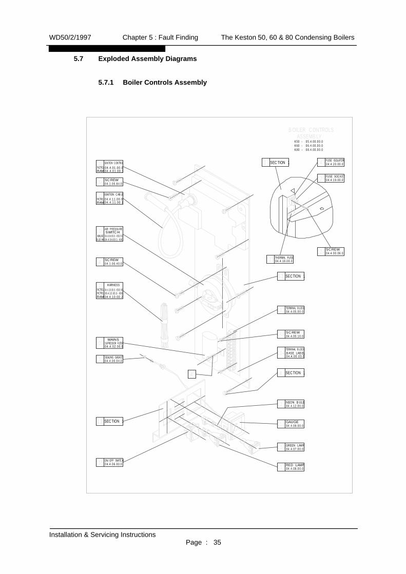
5.7 Exploded Assembly Diagrams
5.7.1 Boiler Controls Assembly
WD50/2/1997 Chapter 5 : Fault Finding The Keston 50, 60 & 80 Condensing Boilers
Installation & Servicing InstructionsPage : 35
K50 - 05.4.00.00.0K60 - 06.4.00.00.0K80 - 08.4.00.00.0
BOILER CONTROLS
barO
I
111 04.4.00.04.0SEALING GASKET
13 SECTION 1
115 04.4.06.00.0ON/OFF SWITCH
04.1.00.84.0SCREW
RED LAMP04.4.08.00.0117
GREEN LAMP04.4.07.00.0116
GAUGE04.4.09.00.0118
NEON BULB04.4.12.00.0121
SCREW04.4.00.10.0
TERMINAL BLOCK04.4.05.00.0113
04.4.04.00.1-K8004.4.04.00.0-K50/60
110 SWITCHAIR PRESSURE
MAUVEBLUE/WH.
04.4.10.00.2
04.4.10.00.0-K50/60119 HARNESSPACTROL
RAM
109 SUPRESSOR FILTERMAINS
04.4.02.00.0
SECTION 14
114 BASE LABELTERMINAL BLOCK
04.4.00.03.0
63 SECTION 1
123 04.4.18.00.0THERMAL FUSE
124 04.4.00.06.0SCREW
125 04.4.19.00.0FUSE SOCKET
SECTION 11
ASSEMBLY
04.4.20.00.0FUSE ISOLATOR143
04.1.00.40.0SCREW4
154
4
158
04.4.11.00.004.4.11.00.1
120PACTROLRAM
04.4.01.00.004.4.01.00.1
108PACTROLRAM
IGNITION CONTROL
IGNITION CABLE
PACTROL 08.4.10.00.0-K80

5.7.2 Waterway, Condensate & Flue Assembly
WD50/2/1997 Chapter 5 : Fault Finding The Keston 50, 60 & 80 Condensing Boilers
Installation & Servicing InstructionsPage : 36
K50 - 05.2.00.00.0K60 - 06.2.00.00.0K80 - 08.2.00.00.0
75 THERMOSTATWATER FLOW OUT
04.2.21.00.0
WATER WAY, CONDENSATE & FLUE ASSEMBLY
04.1.00.80.1SCREW52
51 04.2.13.00.1IGNITER
50 04.2.00.28.2IGNITER GASKET
54 04.2.28.00.0PRESS. TEST FITT.
53 04.2.00.29.1SCREW
48 04.2.00.25.0MANIFOLD
49 04.2.12.00.1SIGHT GLASS
04.2.00.43.1WATER INLET62
47 04.2.00.24.1GASKET
SEEGER RING04.2.00.53.0126
04.2.16.00.0
04.1.00.41.07 SCREW
DRAIN VALVE
04.2.00.54.0GASKET
61
122
4608.2.11.00.0-K8006.2.11.00.0-K6005.2.11.00.0-K50BURNER
LABEL04.2.00.58.0
HIGH VOLTAGE45
04.2.10.00.0-K50/604408.2.10.00.0-K80
HEAT EXCHANGERINSULATION
08.2.01.00.1-K8004.2.01.00.1-K50/60HEAT EXCHANGER
43
04.2.17.00.0THERMOSTATWATER RETURN
64
TRAP HOSECONDENSATE
04.2.00.34.158
04.2.00.57.0HOSE CLAMP67
CONDENSATE HOSE04.2.00.48.171
CONDENSATE TRAP04.2.14.00.159
28 BEND04.2.00.76.0156
PIPE04.2.00.60.0
28 WATER RETURN76
04.2.00.65.0-K50/60
28 WATER RETURN
60 PIPE
08.2.00.65.0-K80
14904.1.00.78.0SCREW
55 04.2.00.32.2
WATER OUT
7
THERMOSTAT04.2.22.00.0
FLOW HIGH LIMIT78
MANIFOLD
79 SWITCHWATER PRESSURE
04.2.23.00.0
04.2.20.00.1AUTO AIR VENT72 04.2.00.66.0
28 WATER FLOW74 PIPE
04.2.00.67.0
28 WATER FLOW83 PIPE
04.2.00.61.077 28 ELBOW
04.2.00.33.256 GASKET04.1.00.79.1150SCREW
EXHAUST PIPE68
73 TEST PLUGCOMBUSTION
04.2.00.49.1
70 THERMOSTATFLUE OVERHEAT
04.2.19.00.0
04.1.00.41.369 SCREW
SECTION 397
04.2.18.00.0-K50/6008.2.18.00.0-K80

5.7.3 Air - Gas Assembly
WD50/2/1997 Chapter 5 : Fault Finding The Keston 50, 60 & 80 Condensing Boilers
Installation & Servicing InstructionsPage : 37
K50 - 05.3.00.00.0K60 - 06.3.00.00.0K80 - 08.3.00.00.0
AIR-GAS ASSEMBLYPRESS. TEST FITT.04.2.28.00.054 SCREW
04.3.00.28.0
104 GAS TEE04.3.00.34.1
PRESSURE SWITCHLOW GAS
04.3.09.00.0
04.3.07.00.0REGULATOR GAS VALVE95
92 RUBBER PLUG04.3.00.18.0
04.3.00.39.0AIR ORIFFICE SCREW88
GASKET94 04.3.00.20.0 54
04.3.00.19.0
AIR/GAS MANIFOLD PLUG93
05.3.00.17.0-K50NG
91
GAS ORIFICE
05.3.00.17.1-K50LPG06.3.00.17.0-K60NG06.3.00.17.1-K60LPG08.3.00.17.0-K80NG08.3.00.17.1-K80LPG
84 FLEXIBLE TUBEAIR/GAS
04.3.05.00.1-K50/K60
103 AIR ADJ. SCREW04.3.10.00.0
08.3.05.00.1-K80
SCREW04.1.00.81.0
04.1.00.38.0SEALING GASKET
GASKET107 04.2.00.33.0
04.3.03.00.081 CAPACITOR
BLOWER80 04.3.01.00.0
82 04.3.04.00.0
BLOWERRUBBER ISOLATOR
17 SECTION 1
AIR HOSE CLAMP04.3.00.21.096
08.3.00.15.0-K8004.3.00.15.0-K50/K60
AIR INLETFLEX. CONNECTOR89
97 04.3.08.00.3
GAS INLETFLEXIBLE TUBE
08.3.00.13.1-K80LPG08.3.00.13.0-K80NG06.3.00.13.1-K60LPG06.3.00.13.0-K60NG05.3.00.13.1-K50LPG
AIR ORIFICE
8705.3.00.13.0-K50NG
GAS INLET GASKET04.3.00.29.099
NUT04.3.00.30.0100
102 04.3.00.32.0HIGH PRESS. TUBE
LOW PRESS. TUBE04.3.00.31.0101
86MANIFOLD AIR/GAS
04.3.06.00.0
90 04.3.00.16.0GAS VALVE SCREW
107
94
98
105
MAIN SOLENOID04.3.07.01.0144
CONNECTOR BLOCK04.3.07.02.0145
151
04.3.07.03.0SECONDARY SOLENOID155
04.1.00.82.0SCREW152
21 04.1.00.76.0SCREW
15
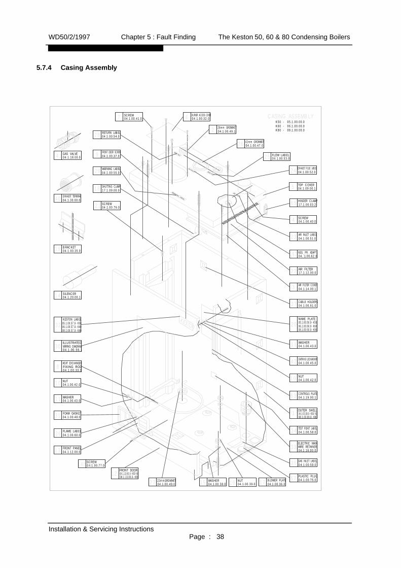
5.7.4 Casing Assembly
WD50/2/1997 Chapter 5 : Fault Finding The Keston 50, 60 & 80 Condensing Boilers
Installation & Servicing InstructionsPage : 38
WARNING LABEL
WATER INLET
EXHAUST WATER OUTLET
AIR INLET
KESTON
CASING ASSEMBLYK50 - 05.1.00.00.0K60 - 06.1.00.00.0K80 - 08.1.00.00.0
SCREW04.1.00.41.07 BURNER ACCESS COVER
04.1.00.32.0628mm GROMMET04.1.00.49.12
42mm GROMMET04.1.00.47.026
FLOW LABEL04.1.00.53.025
24 04.1.00.52.0EXHAUST FLUE LABEL
TOP COVER04.1.09.00.15
HINDER CLAMP17.1.00.03.265
SCREW04.1.00.40.04
AIR INLET LABEL04.1.00.51.023
NEG. PR. ADAPT.04.`1.00.62.0157
04.1.14.00.1AIR FILTER COVER3
AIR FILTER17.1.12.00.022
37 04.1.00.61.0CABLE HOLDERS
NAME PLATE05.1.00.50.0-K5020 06.1.00.50.0-K6008.1.00.50.0-K80
CONTROLS PLATE04.1.19.00.163
11 04.1.00.43.0WASHER
EARTHING LOCKWASHER04.1.00.45.042
NUT04.1.00.42.010
1 04.1.03.00.0-K50/60OUTER SHELL
08.1.03.00.0-K80
34 04.1.00.58.0TEST POINT LABEL
WIRE RETAINER04.1.16.00.0
ELECTRIC MAIN33
GAS INLET LABEL04.1.00.59.035
57 04.1.00.75.0PLASTIC PLUG
16 04.1.00.39.0NUT15 04.1.00.38.0
WASHER22mmGROMMET04.1.00.49.027
08.1.13.00.0-K80
FRONT DOOR04.1.13.00.0-K50/6012
14804.1.00.77.0SCREW
13 04.1.12.00.0FRONT PANEL
36 04.1.00.60.0FLAME LABEL
FOAM GASKET04.1.00.48.031
WASHER04.1.00.43.011
10 04.1.00.42.0NUT
8 FIXING RODHEAT EXCHANGER
04.1.00.33.0
04.1.00.56.1
ILLUSTRATEDWIRING DIAGRAM30
32 05.1.00.57.0-K50KESTON LABEL
SILENCER04.1.20.00.114
19 04.1.00.35.0BRACKET
40 04.1.30.00.0EXHAUST TERMINAL
4104.1.18.00.0GAS VALVE
21 04.1.00.76.0SCREW
18 17.1.09.00.0SHUTTING CLAMP
WARNING LABEL04.1.00.55.029
FRONT DOOR SCREW04.1.00.37.09
RETURN LABEL04.1.00.54.028
BLOWER PLATE04.1.00.36.017
06.1.00.57.0-K6008.1.00.57.0-K80

5.7.5 Exploded Diagrams Parts Reference List
Boiler Controls Assembly (Fig. 5.7.1)GC Number Code DescriptionE01 074 108 Ignition Control Box 170084 110A Air Pressure Switch (Keston 80)379 744 110B Air Pressure Switch (Keston 50 & 60)114 076 113 Electrical Terminal Block114 077 115 On/Off Switch114 078 116 Green (Run) Lamp114 079 117 Red (Lockout) Lamp114 080 119 Pressure Gauge
Waterway, Condensate & Flue Assembly (Fig. 5.7.2)GC Number Code Description114 022 43A Heat Exchanger (Keston 50 & 60)114 023 43B Heat Exchanger (Keston 80)375 523 46A Burner (Keston 50)375 524 46B Burner (Keston 60)375 525 46C Burner (Keston 80)375 526 47 Burner Head Gasket114 028 49 Sight Glass375 527 50 Ignitor Gasket114 120 51 Spark Ignition Electrode114 029 54 Pressure Test Nipple114 032 59 Condensate Trap114 035 61 Return Drain Valve375 530 64 Boiler Thermostat375 532 70 Flue Overheat Thermostat114 043 73 Combustion Test Plug114 042 72 Automatic Air Vent375 533 75 Flow Overheat Thermostat375 534 78 Flow High Limit Thermostat114 045 79 Water Pressure Switch
Air - Gas Assembly (Fig. 5.7.3)GC Number Code Description114 046 80 Combustion Blower114 051/052/053 87A/B/C Air Orifice (Keston 50/60/80 Nat Gas)114 089/090/091 87D/E/F Air Orifice (Keston 50/60/80 LPG)375 536 95 Gas Valve114 029 54 Pressure Test Nipple114 073 105 Low Gas Pressure Switch114 056/057/058 91A/B/C Gas Injector (Keston 50/60/80 Nat Gas)114 061/062/063 91D/E/F Gas Injector (Keston 50/60/80 LPG)
Casing Assembly (Fig. 5.7.4)GC Number Code Description375 541 1A Cabinet Outer Shell (Keston 50 & 60)375 542 1B Cabinet Outer Shell (Keston 80)114 002 20A/B/C Data Badge (Keston 50/60/80)375 543 3 Air Filter Cover114 105 22 Air Filter375 545 5 Cabinet Top Cover375 546 6 Burner Access Cover Plate114 010 30 Illustrated Wiring Diagram375 548 12A Front Door (Keston 50 & 60)375 549 12B Front Door (Keston 80)
WD50/2/1997 Chapter 5 : Fault Finding The Keston 50, 60 & 80 Condensing Boilers
Installation & Servicing InstructionsPage : 39

6. ROUTINE (ANNUAL) SERVICING
To ensure the continued safe and efficient operation of the boiler it is necessary to carry outroutine servicing at regular intervals. The frequency of the servicing will depend upon the particularoperating conditions, but it is recommended that an annual service should be carried out by acompetent engineer.
The appliance has an integral air filter, mounted at the top right hand side of the boiler, to whichthe air intake pipe is connected. This filter should be examined every time the boiler is serviced. Itmay need more frequent inspection according to the condition of the atmosphere in which the airintake terminates.
Note: The air filter can be easily blocked if the boiler is running on or near a building site havingan excess of airborne dust. It is essential, with a premix gas burner, that the air is cleanand free of dust.
It is the law that any service work must be carried out by competent qualified persons.
6.1 Pre-Service Checks
It is recommended that an inspection should be carried out prior to shutting down the unitfor servicing. Remove the front cover by releasing the 2 slotted screws on the top andlifting the cover from the base (Front cover located by two pegs). The following itemsshould be observed:
a. Smooth starting and running of the blower.b. Smooth lighting of the burner.c. Check for leakage of gas, gas/air or combustion products.d. Check for condensate leaks.e. Check the colour and appearance of the flame. A sky blue flame slightly off the
burner gauze is normal. The burner itself should appear dark. Any glow on theburner indicates gauze blockage requiring cleaning, an incorrect gas flow or an airintake blockage.
f. Check that the temperature differential between the flow and return pipes is lessthan 15oC. The temperature difference should be between 10oC and 15oC.
g. Check for water soundness.h. Inspect the flue vent and air intake pipework. Joints must be sound and all
pipework well bracketed.i. Check that there is a steady fall back to the boiler from the flue pipe to allow
condensate to run back into the boiler (See Section 2.8.3 Slope).j. With the boiler operating at a low return temperature (i.e. less than 50oC) check
that the condensate flows freely from the condensate line.
6.1.1 Burner & Heat Exchanger Blockage Checks
i) Turn off the boiler & shut off the gas supply to the boiler.
ii) Remove the pressure point screws from points A & B. Attach a differentialgauge.
iii) Turn on the boiler and wait for the fan to reach full speed. Obviously theburner will not light.
iv) The pressure difference should be lower than : 8 mbar on the Keston 50,8.4 mbar on the Keston 60 and 11.2 mbar on the Keston 80. If not, cleanthe burner.
WD50/2/1997 Chapter 6 : Servicing The Keston 50, 60 & 80 Condensing Boilers
Installation & Servicing InstructionsPage : 40

v) Turn off the electrical supply to the boiler.
vi) Remove the pressure point screw from point C and transfer the tube frompoint A to C, replacing the screw on point A.
vii) Turn on the electrical supply to the boiler (gas still off), wait for the fan toreach full speed.
viii) The pressure difference should be below 11 mbar. If not, clean heatexchanger.
ix) Disconnect the gauge from point B. Refit the screw.
x) Read pressure of point C.
xi) The maximum pressure should be 3 mbar. If the pressure is greater thanthis, check the flue for blockage.
xii) Turn off the electrical supply to the boiler.
xiii) Remove the pressure gauge tube and refit the screw.
xiv) Open the gas service cock.
6.2 Recommended Routine Service
a. Inspect the air filter located at the top right hand side of the boiler. Release theprojecting leaf on the filter box and slide out the filter.
If the filter looks dirty remove the dirt with a vacuum cleaner or by other means. Ifin any doubt renew the filter element.
b. Remove the burner head (Section 7.7) and inspect the burner appearance. Blackmarkings or other discolourations on the gauze indicate too much gas or a lack ofair possibly due to a blocked air filter. Any breakages or damage to the burnermesh indicate the burner must be replaced.
WD50/2/1997 Chapter 6 : Servicing The Keston 50, 60 & 80 Condensing Boilers
Installation & Servicing InstructionsPage : 41
Pressure TestPoint B
Pressure TestPoint A
Burner Heat (From Above)Pressure TestPoint C
CombustionTest Point
Flue OverheatThermostat
HeatExchangerShell
Flue
Fig 6.1.1 Pressure Test Point Locations
&
c. If necessary, either due to discolouration or a high pressure differential betweenpoints A & B in the pre-service checks, clean the burner with a mild householddetergent and rinse under a hot running tap.
d. If necessary, either from visual inspection or a high pressure differential betweenpoints B & C in the pre-service checks, clean the heat exchanger using a suitablestiff plastic bristle brush, vacuum out any large particles and flush the heatexchanger with fresh water until the water flowing from the condensate drain isclear. When brushing the heat exchanger take care not to damage thecondensing plug in the lower half of the heat exchanger.
e. Remove the condensate trap (Section 7.10) and unscrew the cap. Clean byflushing through with clean running water. Reassemble in reverse order.
f. Check the electrodes mounted on the burner head. If the points are damaged orburnt replace them.Check that the spark gap measures 4 mm.
g. Replace the burner head, renewing any gasket as necessary, and reconnect thegas/air supply and the ignition lead. Ensure the flanged gas/air supply joint is airtight.
h. Turn on the electrical supply to the boiler and allow the boiler to reach operatingtemperature levels.
i. Check for gas leakage around the burner head, air/gas flexible hose to the burnerhead and ignitor plug if they have been removed.
j. Visually inspect the burner through the glass spy hole at the burner head (a smallmirror will prove useful).
k. Recheck the burner pressure by following the procedure detailed in Section 4.7
WD50/2/1997 Chapter 6 : Servicing The Keston 50, 60 & 80 Condensing Boilers
Installation & Servicing InstructionsPage : 42

7. REPLACEMENT OF PARTS
INDEX
7.0 GENERAL
7.1 PRECAUTIONS
7.2 ACCESS
7.3 PROCEDURES - GENERAL
7.4 ELECTRICAL
7.4.1 ON/OFF SWITCH
7.4.2 BOILER THERMOSTAT
7.4.3 NEONS
7.4.4 FLOW OVERHEAT, FLOW HIGH LIMIT & FLUE PROTECTION
THERMOMSTATS
7.4.5 WATER PRESSURE SWITCH
7.4.6 IGNITION CONTROL BOX
7.4.7 AIR PRESSURE SWITCH
7.4.8 COMBUSTION BLOWER
7.4.9 GAS CONTROL VALVE
7.4.10 GAS LOW PRESSURE SWITCH
7.5 GAS ORIFICE
7.6 SPARK IGNITION/FLAME DETECTION ELECTRODE
7.7 BURNER HEAD & BURNER
7.8 HEAT EXCHANGER
7.9 AIR FILTER
7.10 CONDENSATE TRAP
7.11 PRESSURE GAUGE
7.12 SIGHT GLASS
7.13 HT IGNITION LEAD
7.14 AIR VENT
7.15 AIR ORIFICE
WD50/2/1997 Chapter 7 : Replacement Of Parts The Keston 50, 60 & 80 Condensing Boilers
Installation & Servicing InstructionsPage : 43

7.0 GENERAL
The following must always be carried out by a competent/qualified person.
7.1 PRECAUTIONS
i) Always switch off the mains electricity supply and disconnect the plug at theisolating switch and socket. (If a switch only is used then remove the fuse.)
ii) Gain access to the appliance (Section 7.2) and turn off the gas supply at theappliance service cock.
7.2 ACCESS
i) Remove the front door by releasing the two slotted screws to the front of the toppanel. The front panel may then be removed by tilting forward and lifting verticallyto disengage the two locating studs in the base of the front panel.
ii) Access to the burner head can be gained by removing the access plate in the toppanel of the appliance.
7.3 REPLACEMENT PROCEDURES
i) Always replace in the reverse order unless otherwise stated.
ii) Electrical connections must be remade in accordance with the Wiring Diagram(Section 5.5).
iii) Test the soundness of any gas carrying or water carrying joint broken during theservice procedures.
7.4 ELECTRICAL COMPONENTS
7.4.1 On/Off Switch (Fig. 5.7.1 item 115)
i) Isolate the appliance (Section 7.1)ii) Gain access (Section 7.2)iii) Remove the push on connectors from the switch taking note of the
correct positions.iv) Press in the catches and push the switch forwards through the control
panel.v) Reassemble (Section 7.3)vi) Check for correct operation of the switch.
7.4.2 Boiler Thermostat (Fig. 5.7.2 item 64)
i) Isolate the appliance (Section 7.1)ii) Gain access (Section 7.2)iii) Remove the push on connectors from the thermostat taking note of the
correct positions.iv) Unscrew the two retaining screws and remove the thermostat.v) Reassemble (Section 7.3)
NB: When fitting the new thermostat it is a requirement to smear athin film of heat sink compound between the thermostat andplate. This, combined with fitting the new thermostat tightly to theplate, ensures a good contact.
WD50/2/1997 Chapter 7 : Replacement Of Parts The Keston 50, 60 & 80 Condensing Boilers
Installation & Servicing InstructionsPage : 44

7.4.3 Neons (Fig. 5.7.1 items 116 & 117)
i) Isolate the appliance (Section 7.1)ii) Gain access (Section 7.2)iii) Remove the push on connectors from the neon taking note of the correct
positions.iv) Press in the catches and push the neon forward through the control
panel.v) Pull the centre core of the neon from its housing to expose the bayonet
fitting bulb.vi) Reassemble (Section 7.3)vii) Check for correct operation of the neons.
7.4.4 Flow Overheat (Fig. 5.7.2 item 75) , Flow High Limit (Fig. 5.7.2 item 78) & FlueProtection Thermostats (Fig. 5.7.2 item 70)
i) Isolate the appliance (Section 7.1)ii) Gain access (Section 7.2)iii) Remove the push on connectors from the thermostat taking note of the
correct positions.iv) Unscrew the two retaining screws and remove the thermostat.v) Flue protection thermostat only
The thermostat seal is maintained via a small 'O' ring between thermostatand flue pipe. If this is damaged on removal it must be replaced.
vi) Reassemble (Section 7.3)NB: When fitting the new thermostat it is a requirement to smear a
thin film of heat sink compound between the thermostat andplate. This, combined with fitting the new thermostat tightly to theplate, ensures a good contact.
7.4.5 Water Pressure Switch (Fig. 5.7.2 item 79)
i) Isolate the appliance (Section 7.1)ii) Shut off the water supply to the appliance.iii) Gain access (Section 7.2)iv) Drain the system to below the level of the appliance using the drain off
tap at the base of the heat exchanger.v) Remove the push on connectors from the water pressure switch taking
note of the correct positions.vi) Unscrew the pressure switch.vii) Reassemble (Section 7.3).
NB: Use a little jointing compound or PTFE tape on the thread.viii) Refill the system (See Section 4 - Commissioning).
7.4.6 Ignition Control Box (Fig. 5.7.1 item 108)
i) Isolate the appliance (Section 7.1)ii) Gain access (Section 7.2)iii) Remove the HT ignition lead.iv) Pull off the multi-pin connector away from the box.v) Unscrew the two screws securing the control box to the casing and
remove the box.vi) Reassemble (Section 7.3)
WD50/2/1997 Chapter 7 : Replacement Of Parts The Keston 50, 60 & 80 Condensing Boilers
Installation & Servicing InstructionsPage : 45

7.4.7 Air Pressure Switch (Fig. 5.7.1 item 110)
i) Isolate the appliance (Section 7.1)ii) Gain access (Section 7.2)iii) Remove the push on connectors from the air pressure switch taking note
of the correct positions.iv) Disconnect the union to one plastic tube connection and pull off the
second plastic tube from the air pressure switch.v) Unscrew the two screws mounting the air pressure switch body to the
boiler casing.vi) Reassemble (Section 7.3)
NB: Ensure the yellow/green earth connection tag is securely fixedbehind the lower mounting screw.
7.4.8 Combustion Blower (Fig. 5.7.3 item 80)
i) Isolate the appliance (Section 7.1)ii) Gain access (Section 7.2)iii) Remove the cover plate to the electrical connections on the blower motor
by removing the four retaining screws.iv) Disconnect the wires to the combustion blower taking note of the correct
positions.v) Remove the allen screws fixing the air intake pipe flange and the gas/air
mixture pipe flange to the blower.vi) Undo the two nuts securing the combustion blower base plate to the
cabinet base and lift out the combustion blower.vii) Unscrew the three bolts fixing the base plate and anti-vibration mounts to
the combustion blower.viii) Reassemble (Section 7.3)
NB: When reassembling inspect any gaskets for damage and replaceif necessary.
ix) Reset the gas rate (See Section 4 - Commissioning)
7.4.9 Gas Control Valve (Fig. 5.7.3 item 95)
i) Isolate the appliance (Section 7.1)ii) Gain access (Section 7.2)iii) Remove the cover concealing the electrical connections on the front of
the gas valve.iv) Remove the push on connectors exposed taking note of the correct
positions.v) Remove the push on connectors to the gas low pressure switch taking
note of the correct positions.vi) Remove the earth connection to the side of the gas valve.vii) Remove the four allen bolts securing the gas inlet flanged connections to
the gas control valve.viii) Undo the four bolts fixing the base of the gas control valve to the gas
outlet block.ix) Remove the gas valve.x) Unscrew the gas low pressure switch at its connection to the gas control
valve body.xi) Reassemble (Section 7.3)xii) Reset the gas rate (See Section 4 - Commissioning)
WD50/2/1997 Chapter 7 : Replacement Of Parts The Keston 50, 60 & 80 Condensing Boilers
Installation & Servicing InstructionsPage : 46

7.4.10 Gas Low Pressure Switch (Fig. 5.7.3 item 105)
i) Isolate the appliance (Section 7.1)ii) Gain access (Section 7.2)iii) Remove the push on connectors to the gas low pressure switch taking
note of the correct positions.iv) Unscrew the gas low pressure switch from the brass holder.v) Reassemble (Section 7.3)
7.5 GAS ORIFICE (Fig 5.7.3 item 91)
i) Isolate the appliance (Section 7.1)ii) Gain access (Section 7.2)iii) Unscrew and remove the brass plug from the gas outlet block.iv) Remove the rubber seal from the injector housing.v) Insert a flat blade screwdriver into the exposed hole and unscrew the gas injector.vi) Check the injector is the correct size for the boiler size and fuel type.vii) Reassemble (Section 7.3)
NB : When fitting the new gas injector ensure that the injector is screwed fully home past the gas port into the chamber from the gas valve. viii) Reset the gas pressure (See Section 4 - Commissioning)
7.6 SPARK IGNITION/FLAME DETECTION ELECTRODE (Fig. 5.7.2 item 51)
i) Isolate the appliance (Section 7.1)ii) Gain access (Section 7.2)iii) Remove the pull off HT lead to the spark ignition electrode.iv) Remove the burner head (Section 7.7 steps iv) to vii).v) Undo the screws to the spark ignition electrode flange located on the burner
head and withdraw the spark ignition electrode.vi) Reassemble (Section 7.3)
NB: When reassembling inspect the gasket for damage and replace ifnecessary. With the new spark ignition electrode in place it is essential toensure the gap between the tip of the electrode and the burner surface is4 mm. Distance above or below 4 mm will affect the ignition performance.If necessary gently bend the electrode taking care not to damage theceramic insulator.
7.7 BURNER HEAD & BURNER (Fig. 5.7.2 items 46 & 48)
i) Isolate the appliance (Section 7.1)ii) Gain access (Section 7.2)iii) Remove the pull off HT lead to the spark ignition/flame detection electrode head.iv) Remove the four screws retaining the access panel (Fig. 5.7.4 item 6) and
remove the access panel from the top of the cabinet.v) Remove the two allen screws fixing the flange gas/air mixture pipe connection to
the burner head.vi) Remove the four allen screws fixing the burner head to the top of the heat
exchanger.vii) Withdraw the burner & burner head from the top of the heat exchanger through
the access panel opening in the top of the cabinet.viii) Unscrew the burner from the burner head taking care not to damage the burner
mesh.ix) Reassemble (Section 7.3)
NB: When reassembling inspect any gaskets for damage and replace ifnecessary. Set the spark gas as detailed in Section 7.6.
x) Reset the gas rate (see Section 4 - Commissioning)
WD50/2/1997 Chapter 7 : Replacement Of Parts The Keston 50, 60 & 80 Condensing Boilers
Installation & Servicing InstructionsPage : 47

7.8 HEAT EXCHANGER (Fig. 5.7.2 item 43)
i) Isolate the appliance (Section 7.1)ii) Gain access (Section 7.2)iii) Shut of the water supply to the appliance.iv) Remove the burner head (Section 7.7)v) Drain the system to below the level of the appliance using the drain off tap at the
base of the heat exchanger.vi) Remove the boiler thermostat (Section 7.4.2)vii) Remove the push on connectors to the water pressure switch, flow overheat
thermostat, flow high limit thermostat and flue protection thermostat taking note ofthe correct positions.
viii) Remove the condensate trap (Section 7.10)ix) Remove the pressure gauge phial located next to the drain off tap.x) Disconnect the flow and return compression couplings to the flow and return
pipes exiting the top of the boiler.xi) Remove the push on flue connection to the flue pipe exiting the top of the boiler.xii) Remove the complete air filter assembly and flexible air pipe.xiii) Remove the nut fixing the strap retaining the base of the heat exchanger and pull
out the strap by unhooking it from its fixing behind the heat exchanger.xiv) Remove the allen screw securing the top of the heat exchanger to its mounting
bracket.xv) Remove the five screws fixing the top of the cabinet.xvi) Remove the heat exchanger, with pipework attached, & the top of the cabinet.xvii) Separate the top of the cabinet from the combined assembly.xviii) Remove the flow and flue pipework from the heat exchanger (Replacement heat
exchangers are supplied with return pipework attached).xix) Reassemble (Section 7.3)xx) Recommission (Section 4 - Commissioning)
7.9 AIR FILTER (Fig. 5.7.4 item 22)
i) Isolate the appliance (Section 7.1)ii) Gain access (Section 7.2)iii) Drop the lower section of the air filter housing by pulling forward the securing flap.iv) Open the lower section as far as possible and pull out the combined paper filter
element with rubber seal.v) Reassemble (Section 7.3)
NB: When fitting the new air filter take care to ensure that the new filter is placed to cover completely the air intake entry into the boiler cabinet.
7.10 CONDENSATE TRAP (Fig. 5.7.2 item 59)
i) Isolate the appliance (Section 7.1)ii) Gain access (Section 7.2)iii) Disconnect the condensate line from the base of the heat exchanger.iv) Disconnect the condensate line from the base of the flue assembly.v) Disconnect the condense lines from the projection of the condensate trap from
the base of the cabinet.vi) Withdraw the condensate trap.vii) Mop up any spilled condensate.viii) Reassemble (Section 7.3)
NB: When re-fitting condensate trap pour water into the condensate hosefrom the base of the heat exchanger until nearly full. Then reconnect thecondensate hose to the base of the heat exchanger.
WD50/2/1997 Chapter 7 : Replacement Of Parts The Keston 50, 60 & 80 Condensing Boilers
Installation & Servicing InstructionsPage : 48

7.11 PRESSURE GAUGE (Fig. 5.7.1 item 119)
i) Isolate the appliance (Section 7.1) and shut off the boiler from the water circuit.ii) Gain access (Section 7.2)iii) Shut off the pressure measurement point at the return drain valve located at the
base of the heat exchanger.iv) Remove the phial from its mounting at the return pipe entry to the base of the heat
exchanger.v) Press in the catches and push the pressure gauge forward through the control
panel.vi) Reassemble (Section 7.3)vii) Refill the system (See Section 4 - Commissioning)
7.12 SIGHT GLASS (Fig. 5.7.2 item 49)
i) Isolate the appliance (Section 7.1)ii) Gain access (Section 7.2)iii) Unscrew the sight glass fitting from the burner head.iv) Reassemble (Section 7.3)
7.13 HT IGNITION LEAD (Fig 5.7.1 item 120)
i) Isolate the appliance (Section 7.1)ii) Gain access (Section 7.2)iii) Remove the lead from the electrode and the ignition control box.iv) Reassemble (Section 7.3)
7.14 AIR VENT (Fig. 5.7.2 item 72)
i) Isolate the appliance (Section 7.1)ii) Gain access (Section 7.2)iii) Shut off the water supply to the appliance.iv) Gain access (Section 7.2)v) Drain the system to below the level of the appliance using the drain off tap at the
base of the heat exchanger.vi) Unscrew the air vent.vii) Reassemble (Section 7.3)viii) Refill the system (See Section 4 - Commissioning)
7.15 Air Orifice (Fig. 5.7.3 item 87)
i) Isolate the appliance (Section 7.1)ii) Gain access (Section 7.2)iii) Disconnect the flexible air intake hose from the air inlet manifold (Fig 5.7.3 item
102)iv) Unscrew the air orifice grub screw (Fig 5.7.3 item 83) to release the air orifice.v) Lift the air orifice from its seat in the air inlet manifold.vi) Reassemble (Section 7.3)NB: When replacing the air orifice ensure that the new orifice is seated with the
chamfer facing upwards.
WD50/2/1997 Chapter 7 : Replacement Of Parts The Keston 50, 60 & 80 Condensing Boilers
Installation & Servicing InstructionsPage : 49
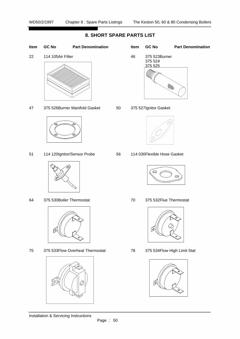
8. SHORT SPARE PARTS LIST
Item GC No Part Denomination Item GC No Part Denomination
22 114 105Air Filter 46 375 523Burner375 524375 525
47 375 526Burner Manifold Gasket 50 375 527Ignitor Gasket
51 114 120Ignitor/Sensor Probe 56 114 030Flexible Hose Gasket
64 375 530Boiler Thermostat 70 375 532Flue Thermostat
75 375 533Flow Overheat Thermostat 78 375 534Flow High Limit Stat
WD50/2/1997 Chapter 8 : Spare Parts Listings The Keston 50, 60 & 80 Condensing Boilers
Installation & Servicing InstructionsPage : 50

Item GC No Part Denomination Item GC No Part Denomination
94 375 535Gas Valve Outlet Gasket 107 375 529Flexible Hose Gasket95 375 536Gas Valve99 375 537Gas Inlet Gasket
108 E01 074 Ignition Control Box 110 170 084Air Pressure Switch379 744
120 E01 075 HT Ignition Cable
WD50/2/1997 Chapter 8 : Spare Parts Listings The Keston 50, 60 & 80 Condensing Boilers
Installation & Servicing InstructionsPage : 51
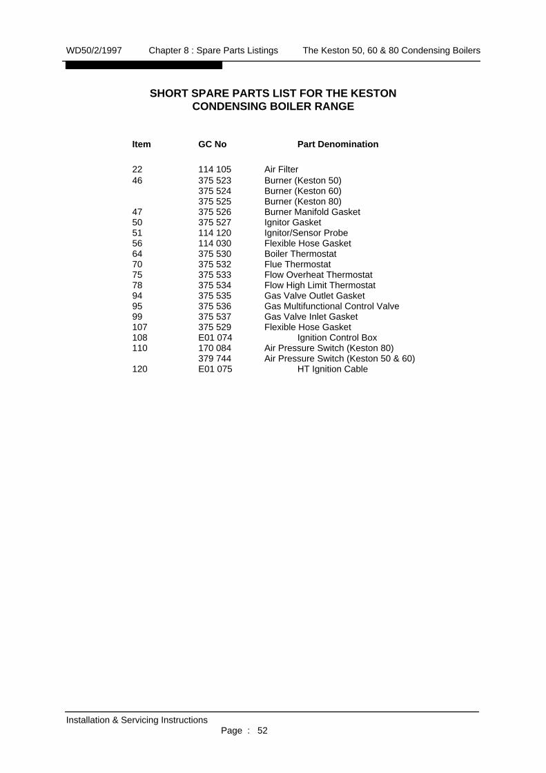
SHORT SPARE PARTS LIST FOR THE KESTONCONDENSING BOILER RANGE
Item GC No Part Denomination
22 114 105 Air Filter46 375 523 Burner (Keston 50)
375 524 Burner (Keston 60)375 525 Burner (Keston 80)
47 375 526 Burner Manifold Gasket50 375 527 Ignitor Gasket51 114 120 Ignitor/Sensor Probe56 114 030 Flexible Hose Gasket64 375 530 Boiler Thermostat70 375 532 Flue Thermostat75 375 533 Flow Overheat Thermostat78 375 534 Flow High Limit Thermostat94 375 535 Gas Valve Outlet Gasket95 375 536 Gas Multifunctional Control Valve99 375 537 Gas Valve Inlet Gasket107 375 529 Flexible Hose Gasket108 E01 074 Ignition Control Box110 170 084 Air Pressure Switch (Keston 80)
379 744 Air Pressure Switch (Keston 50 & 60)120 E01 075 HT Ignition Cable
WD50/2/1997 Chapter 8 : Spare Parts Listings The Keston 50, 60 & 80 Condensing Boilers
Installation & Servicing InstructionsPage : 52

† Read Installation Manual Carefully† For open systems ensure that there is at least 8 feet head of
water pressure at the top of the boiler.† DO NOT remove the dust caps from the air and exhaust pipes
until ready to connect.† Ensure that ALL dust particles, filings , plastic chips etc. are
removed from the inlet pipe.† If the installation is a replacement the system must be flushed
clean. System should be drained hot, then refilled, then drainedagain until the water is clean.
† Ensure that there is a proper electrical supply ie 230V fused at5A.
† Take great care with pipe connections to ensure that nodamage is done to the internal pipework.
† Ensure that the 22mm condensate pipe is not exposed tofreezing conditions.
† Make sure that the exhaust pipe terminates away from windowsor vents and is out of reach.
† Make sure that the air inlet and exhaust pipe outlets are at least350mm apart.
† Check tightness of all connections in the boiler before firing.† Ensure that the terminals supplied are fitted to both the exhaust
and air inlet pipes.† Ensure that the air inlet terminal is facing upwards to prevent
entry of rain.† The system must be free from air before firing.† The pump must always run when the boiler is firing.† Gravity circuits are not allowed.† If TRV's are installed on radiators ensure that a bypass is
installed to maintain required flow.
WD 92/0/1997
KESTON CONDENSING BOILERS
IMPORTANT KESTON 50, 60 & 80
INSTALLATION KEY POINTS