installation and support guide - kev009.comps-2.kev009.com/pccbbs/pc_servers_pdf/gc26749001.pdf ·...
TRANSCRIPT

IBM TotalStorage FAStT Storage Manager Version8.21 forUNIX and AIX Environments
Installation and Support Guide
GC26-7490-01
Read Before UsingThe IBM Agreement for Licensed Internal Code is included in this book. Carefully read the agreement. By using thisMachine or feature/MES you agree to abide by the terms of this agreement and applicable copyright laws.
���


IBM TotalStorage FAStT Storage Manager Version8.21 forUNIX and AIX Environments
Installation and Support Guide
GC26-7490-01
���

Note:Before using this information and the product it supports, read the information in “Notices” on page 135.
Second Edition (November 2002)
This edition replaces GC26–7490–00
© Copyright International Business Machines Corporation 2002. All rights reserved.US Government Users Restricted Rights – Use, duplication or disclosure restricted by GSA ADP Schedule Contractwith IBM Corp.

Contents
Figures . . . . . . . . . . . . . . . . . . . . . . . . . . . vii
Tables . . . . . . . . . . . . . . . . . . . . . . . . . . . . ix
About this document . . . . . . . . . . . . . . . . . . . . . . xiWho should read this document . . . . . . . . . . . . . . . . . . . xiHow this document is organized . . . . . . . . . . . . . . . . . . . xiRelated publications . . . . . . . . . . . . . . . . . . . . . . . xii
Documents . . . . . . . . . . . . . . . . . . . . . . . . . xiiAdditional reference . . . . . . . . . . . . . . . . . . . . . . xiiiOnline help . . . . . . . . . . . . . . . . . . . . . . . . . xiiiWeb sites . . . . . . . . . . . . . . . . . . . . . . . . . . xiii
How to send your comments. . . . . . . . . . . . . . . . . . . . xiv
Chapter 1. Introduction . . . . . . . . . . . . . . . . . . . . . . 1Storage Manager 8.21 features . . . . . . . . . . . . . . . . . . . 2Storage Manager 8 software packages . . . . . . . . . . . . . . . . 3
Storage Manager 8 client software package. . . . . . . . . . . . . . 4Storage Manager 8 agent software package . . . . . . . . . . . . . 5Storage Manager 8 utility software package. . . . . . . . . . . . . . 5RDAC . . . . . . . . . . . . . . . . . . . . . . . . . . . 5
Storage subsystem management methods . . . . . . . . . . . . . . . 5Host-agent (in-band) management method . . . . . . . . . . . . . . 6Direct (out-of-band) management method . . . . . . . . . . . . . . 7
Operating system requirements . . . . . . . . . . . . . . . . . . . 9Setting up IP addresses for FAStT storage controllers . . . . . . . . . . . 9
Chapter 2. Installing storage management station software on AIX systems 11Hardware and firmware requirements. . . . . . . . . . . . . . . . . 11
Creating a direct-attached configuration . . . . . . . . . . . . . . . 12Creating a SAN-attached configuration . . . . . . . . . . . . . . . 12
AIX restrictions . . . . . . . . . . . . . . . . . . . . . . . . . 13Installing the host software on AIX hosts . . . . . . . . . . . . . . . 13
Prerequisites. . . . . . . . . . . . . . . . . . . . . . . . . 13Installing SMruntime on AIX hosts . . . . . . . . . . . . . . . . . 13
Installing SMclient on AIX hosts. . . . . . . . . . . . . . . . . . . 14Installing host RDAC software on AIX hosts . . . . . . . . . . . . . . 14
Prerequisites. . . . . . . . . . . . . . . . . . . . . . . . . 14Installing RDAC on AIX hosts . . . . . . . . . . . . . . . . . . 15
Performing the initial configuration of storage subsystems on AIX hosts . . . . 15Updating FAStT firmware and NVSRAM . . . . . . . . . . . . . . 16Setting up an AIX host group. . . . . . . . . . . . . . . . . . . 17
AIX configuration information. . . . . . . . . . . . . . . . . . . . 17Viewing and setting attributes of the RDAC driver for AIX . . . . . . . . 17Viewing ODM attributes in AIX . . . . . . . . . . . . . . . . . . 22Changing ODM attribute settings in AIX . . . . . . . . . . . . . . . 23Verifying the installation and configuration of AIX hosts . . . . . . . . . 24Identifying the controller ID numbers . . . . . . . . . . . . . . . . 25Identifying device names and bus numbers . . . . . . . . . . . . . 26Identifying logical drives by operating system device names . . . . . . . 29
Disk array errors . . . . . . . . . . . . . . . . . . . . . . . . 31Redistributing volumes in case of failure . . . . . . . . . . . . . . 32
© Copyright IBM Corp. 2002 iii

Chapter 3. Installing storage management station software on HP-UXsystems . . . . . . . . . . . . . . . . . . . . . . . . . . 35
Hardware and firmware requirements . . . . . . . . . . . . . . . . 35Installing the host software on HP-UX hosts . . . . . . . . . . . . . . 36
Prerequisites. . . . . . . . . . . . . . . . . . . . . . . . . 36Installing SMruntime on HP-UX hosts . . . . . . . . . . . . . . . 36Installing the SMclient on HP-UX hosts . . . . . . . . . . . . . . . 37Installing the client software on HP-UX hosts . . . . . . . . . . . . . 38Installing the SMagent on HP-UX hosts . . . . . . . . . . . . . . . 38Installing SMutil on HP-UX hosts . . . . . . . . . . . . . . . . . 38Configuring storage and partitioning for heterogeneous environments . . . . 39
Enabling multipath I/O with PV-links . . . . . . . . . . . . . . . . . 41Identifying the controller ID numbers . . . . . . . . . . . . . . . . . 44Identifying device names and bus numbers . . . . . . . . . . . . . . 44
Chapter 4. Installing storage management station software on Solarissystems . . . . . . . . . . . . . . . . . . . . . . . . . . 47
Hardware and firmware requirements . . . . . . . . . . . . . . . . 47Installing the runtime software on Solaris hosts . . . . . . . . . . . . . 48
Prerequisites. . . . . . . . . . . . . . . . . . . . . . . . . 48Procedure. . . . . . . . . . . . . . . . . . . . . . . . . . 48
Installing the client software on Solaris hosts . . . . . . . . . . . . . . 49Prerequisites. . . . . . . . . . . . . . . . . . . . . . . . . 49Installing SMclient on Solaris hosts . . . . . . . . . . . . . . . . 49
Installing host software on Solaris hosts. . . . . . . . . . . . . . . . 50Prerequisites. . . . . . . . . . . . . . . . . . . . . . . . . 51Installing RDAC on Solaris hosts . . . . . . . . . . . . . . . . . 51Installing SMagent on Solaris hosts . . . . . . . . . . . . . . . . 52Installing SMutil on Solaris Host . . . . . . . . . . . . . . . . . 53
Performing the initial configuration of storage subsystems on Solaris hosts . . . 54Uninstalling Storage Manager 8.21 software . . . . . . . . . . . . . . 55Default partitioning for Solaris devices . . . . . . . . . . . . . . . . 55Configuring JNI host bus adapter cards . . . . . . . . . . . . . . . . 56Variable settings for JNI adapter cards . . . . . . . . . . . . . . . . 56Setting the Solaris system host type . . . . . . . . . . . . . . . . . 57
Chapter 5. Completing the software installation. . . . . . . . . . . . 59Failover protection . . . . . . . . . . . . . . . . . . . . . . . 59Changing the host type . . . . . . . . . . . . . . . . . . . . . . 59Heterogeneous hosts overview . . . . . . . . . . . . . . . . . . . 60Configuring storage subsystems . . . . . . . . . . . . . . . . . . 60
Starting the Enterprise Management window . . . . . . . . . . . . . 60Configuring alert notifications. . . . . . . . . . . . . . . . . . . . 62Starting the Subsystem Management window . . . . . . . . . . . . . 63
Renaming storage subsystems . . . . . . . . . . . . . . . . . . 64Performing optional storage subsystem management tasks . . . . . . . 64
Chapter 6. Storage Manager 8.21 with high-availability cluster services 67General information . . . . . . . . . . . . . . . . . . . . . . . 67Prerequisites for HP-UX . . . . . . . . . . . . . . . . . . . . . 67Prerequisites for Solaris and Veritas Cluster Server . . . . . . . . . . . 67
General hardware requirements. . . . . . . . . . . . . . . . . . 67System dependencies . . . . . . . . . . . . . . . . . . . . . 67
Storage Manager 8.21 with General Parallel File System (GPFS) . . . . . . 68Minimum AIX, PSSP, HACMP, and GPFS software requirements . . . . . 68FAStT software and firmware requirements . . . . . . . . . . . . . 69
iv IBM TotalStorage FAStT Storage Manager Version 8.21 for UNIX and AIX Environments: Installation and Support Guide
Configuration limitations . . . . . . . . . . . . . . . . . . . . 69Other usage notes specific to PSSP/GPFS environments . . . . . . . . 69GPFS/PSSP logical configuration diagrams . . . . . . . . . . . . . 69
Chapter 7. FlashCopy and the FAStT Storage Server. . . . . . . . . . 77Overview of FlashCopy . . . . . . . . . . . . . . . . . . . . . . 77Enabling FlashCopy . . . . . . . . . . . . . . . . . . . . . . . 78
Obtaining the feature enable identifier . . . . . . . . . . . . . . . 78Generating the feature key file . . . . . . . . . . . . . . . . . . 78Using the feature key file to enable FlashCopy . . . . . . . . . . . . 79
FlashCopy parameters . . . . . . . . . . . . . . . . . . . . . . 79FlashCopy logical drives . . . . . . . . . . . . . . . . . . . . 80Viewing FlashCopy logical drive failure settings . . . . . . . . . . . . 80Estimating FlashCopy repository logical drive capacity . . . . . . . . . 83Estimating FlashCopy repository life . . . . . . . . . . . . . . . . 84
Using FlashCopy . . . . . . . . . . . . . . . . . . . . . . . . 85Checking the status of the FlashCopy premium feature . . . . . . . . . 86Creating a FlashCopy logical drive. . . . . . . . . . . . . . . . . 87Mapping a FlashCopy drive to a host. . . . . . . . . . . . . . . . 98Viewing the FlashCopy logical drive status . . . . . . . . . . . . . 101Disabling a FlashCopy logical drive . . . . . . . . . . . . . . . . 106Recreating a FlashCopy logical drive . . . . . . . . . . . . . . . 108Resizing a FlashCopy repository drive . . . . . . . . . . . . . . . 109Deleting a FlashCopy drive . . . . . . . . . . . . . . . . . . . 111
Using FlashCopy with UNIX regular disks. . . . . . . . . . . . . . . 113Instructions for Solaris . . . . . . . . . . . . . . . . . . . . . 113Instructions for HP-UX: Logical Drive Manager . . . . . . . . . . . . 116
Script editor and command-line interface . . . . . . . . . . . . . . . 120Missing logical drives . . . . . . . . . . . . . . . . . . . . . . 120
Appendix A. AIX system requirements . . . . . . . . . . . . . . . 123Hardware requirements . . . . . . . . . . . . . . . . . . . . . 123Software requirements . . . . . . . . . . . . . . . . . . . . . 123RDAC installation requirements . . . . . . . . . . . . . . . . . . 123
Appendix B. HP-UX system requirements . . . . . . . . . . . . . 125
Appendix C. Solaris system requirements . . . . . . . . . . . . . 127
Appendix D. MC Service Guard configuration details . . . . . . . . . 129
Appendix E. JNI Host Bus Adapter settings . . . . . . . . . . . . . 131
Notices . . . . . . . . . . . . . . . . . . . . . . . . . . . 135Trademarks. . . . . . . . . . . . . . . . . . . . . . . . . . 135IBM agreement for licensed internal code. . . . . . . . . . . . . . . 136
Actions you must not take . . . . . . . . . . . . . . . . . . . 137
Glossary . . . . . . . . . . . . . . . . . . . . . . . . . . 139
Index . . . . . . . . . . . . . . . . . . . . . . . . . . . . 141
Contents v

vi IBM TotalStorage FAStT Storage Manager Version 8.21 for UNIX and AIX Environments: Installation and Support Guide

Figures
1. Host-agent (in-band) managed storage subsystems . . . . . . . . . . . . . . . . . . 62. Direct (out-of-band) managed storage subsystems . . . . . . . . . . . . . . . . . . . 83. Controller Properties window . . . . . . . . . . . . . . . . . . . . . . . . . . 264. Use of commands applied to validating system configuration. . . . . . . . . . . . . . . 275. Change Mappings window . . . . . . . . . . . . . . . . . . . . . . . . . . . 306. Volume Properties window . . . . . . . . . . . . . . . . . . . . . . . . . . . 317. Device names . . . . . . . . . . . . . . . . . . . . . . . . . . . . . . . . 428. Controller Properties window . . . . . . . . . . . . . . . . . . . . . . . . . . 449. Device identification information . . . . . . . . . . . . . . . . . . . . . . . . . 45
10. Mappings window . . . . . . . . . . . . . . . . . . . . . . . . . . . . . . 4611. Initial Automatic Discovery window . . . . . . . . . . . . . . . . . . . . . . . . 6112. Enterprise Management window . . . . . . . . . . . . . . . . . . . . . . . . . 6213. Subsystem Management window . . . . . . . . . . . . . . . . . . . . . . . . . 6414. RVSD Cluster Configuration example with single FAStT500/700 - Storage Manager v7.10 or
v8.21, shown with 2 partitions (4 maximum) per FAStT . . . . . . . . . . . . . . . . . 7015. RVSD Cluster Configuration example with multiple FAStT500/700 - Storage Manager v7.10 or
v8.21, shown with 2 partitions per FAStT . . . . . . . . . . . . . . . . . . . . . . 7116. RVSD Cluster Configuration example with multiple FAStT500/700 - Storage Manager v7.10 or
v8.21, shown with 1 partition per FAStT . . . . . . . . . . . . . . . . . . . . . . 7217. Typical RVSD Cluster Configuration example with multiple FAStT500/700 - Storage Manager
v7.10 or v8.21, shown with 1 partition per FAStT . . . . . . . . . . . . . . . . . . . 7318. HACMP/GPFS Cluster Configuration example with single FAStT500/700, shown with one partition
per FAStT . . . . . . . . . . . . . . . . . . . . . . . . . . . . . . . . . 7419. HACMP/GPFS Cluster Configuration example with multiple FAStT500/700, shown with two
partitions per FAStT. . . . . . . . . . . . . . . . . . . . . . . . . . . . . . 7520. FlashCopy reposity logical drive properties . . . . . . . . . . . . . . . . . . . . . 8121. Repository capacity settings. . . . . . . . . . . . . . . . . . . . . . . . . . . 8222. Listing premium features . . . . . . . . . . . . . . . . . . . . . . . . . . . . 8623. Features list showing FlashCopy enabled . . . . . . . . . . . . . . . . . . . . . . 8624. Feature list showing FlashCopy not enabled . . . . . . . . . . . . . . . . . . . . . 8725. FlashCopy feature icon . . . . . . . . . . . . . . . . . . . . . . . . . . . . 8726. FlashCopy feature icon disabled . . . . . . . . . . . . . . . . . . . . . . . . . 8727. Create FlashCopy menu options . . . . . . . . . . . . . . . . . . . . . . . . . 8828. Create a FlashCopy Logical Drive Wizard startup . . . . . . . . . . . . . . . . . . . 8929. Wizard Introduction window . . . . . . . . . . . . . . . . . . . . . . . . . . . 9030. Allocate Capacity window. . . . . . . . . . . . . . . . . . . . . . . . . . . . 9131. Specify Logical Drive Parameters . . . . . . . . . . . . . . . . . . . . . . . . . 9232. Preview window . . . . . . . . . . . . . . . . . . . . . . . . . . . . . . . 9333. Specify Array Parameters window . . . . . . . . . . . . . . . . . . . . . . . . 9434. Specify Names window . . . . . . . . . . . . . . . . . . . . . . . . . . . . 9535. Specify Repository Drive Capacity . . . . . . . . . . . . . . . . . . . . . . . . 9636. Preview window . . . . . . . . . . . . . . . . . . . . . . . . . . . . . . . 9737. FlashCopy volumes . . . . . . . . . . . . . . . . . . . . . . . . . . . . . . 9838. Undefined FlashCopy disk . . . . . . . . . . . . . . . . . . . . . . . . . . . 9939. Define Additional Mapping . . . . . . . . . . . . . . . . . . . . . . . . . . . 9940. Define Additional Mapping window . . . . . . . . . . . . . . . . . . . . . . . . 10041. Mapped FlashCopy logical disk . . . . . . . . . . . . . . . . . . . . . . . . . 10142. FlashCopy icon states . . . . . . . . . . . . . . . . . . . . . . . . . . . . 10243. Repository Logical Drive Properties . . . . . . . . . . . . . . . . . . . . . . . 10344. Base Repository Logical Drive Properties . . . . . . . . . . . . . . . . . . . . . 10445. Repository drive warning threshold . . . . . . . . . . . . . . . . . . . . . . . . 10546. Choosing to disable the FlashCopy drive . . . . . . . . . . . . . . . . . . . . . 10747. Disable FlashCopy confirmation window . . . . . . . . . . . . . . . . . . . . . . 107
© Copyright IBM Corp. 2002 vii

48. Icon showing the disabled FlashCopy logical drive . . . . . . . . . . . . . . . . . . 10849. Recreating a FlashCopy. . . . . . . . . . . . . . . . . . . . . . . . . . . . 10950. Deleting the FlashCopy logical drive . . . . . . . . . . . . . . . . . . . . . . . 11251. Delete FlashCopy Logical Drive Dialog window . . . . . . . . . . . . . . . . . . . 112
viii IBM TotalStorage FAStT Storage Manager Version 8.21 for UNIX and AIX Environments: Installation and Support Guide

Tables
1. Installation sequences of Storage Manager 8.21 software packages by host type . . . . . . . 42. Supported versions of hardware for AIX systems . . . . . . . . . . . . . . . . . . . 113. Attributes for dar devices . . . . . . . . . . . . . . . . . . . . . . . . . . . . 184. Attributes for dac devices. . . . . . . . . . . . . . . . . . . . . . . . . . . . 205. Attributes for hdisk devices . . . . . . . . . . . . . . . . . . . . . . . . . . . 206. Supported versions of hardware for HP-UX systems . . . . . . . . . . . . . . . . . . 357. Primary and secondary path matrix information. . . . . . . . . . . . . . . . . . . . 438. Supported versions of hardware for Solaris systems . . . . . . . . . . . . . . . . . . 479. JNI adapter configuration files . . . . . . . . . . . . . . . . . . . . . . . . . . 56
10. Filesets required for AIX 4.3.3 RDAC . . . . . . . . . . . . . . . . . . . . . . . 12311. Filesets required for AIX 5.1 RDAC . . . . . . . . . . . . . . . . . . . . . . . 12312. HP-UX kernel parameter configuration requirements . . . . . . . . . . . . . . . . . 12513. Configuration file name: /kernel/drv/fca-pci.conf . . . . . . . . . . . . . . . . . . . 13114. Configuration file name: /kernel/drv/jnic146x.conf . . . . . . . . . . . . . . . . . . 13115. Configuration file name: /kernel/drv/jnic.conf . . . . . . . . . . . . . . . . . . . . 13216. Configuration file name: /kernel/drv/fcaw.conf . . . . . . . . . . . . . . . . . . . . 132
© Copyright IBM Corp. 2002 ix

x IBM TotalStorage FAStT Storage Manager Version 8.21 for UNIX and AIX Environments: Installation and Support Guide

About this document
This document provides information about setting up, installing, configuring, andworking with the IBM TotalStorage Fibre Array Storage Technology (FAStT) StorageManager Version 8.21 in UNIX® and AIX™ environments.
Throughout this document, the terms storage management software and StorageManager 8.21 refer to the IBM TotalStorage FAStT Storage Manager Version 8.21.Individual components of the storage management software are identified by name.
Use this document to:
v Determine the hardware and software that is required to install the managementsoftware into your subsystem network
v Integrate the necessary hardware components
v Install the management software
v Upgrade controller NVSRAM and firmware
v Identify management features that are unique to your specific installation
Who should read this documentThis document is intended for system administrators and storage administratorswho are responsible for installing software. Readers should have knowledge ofRAID, SCSI, and fibre-channel technology, and should also have workingknowledge of the applicable operating systems that are used with the managementsoftware.
How this document is organizedChapter 1, “Introduction” on page 1 provides an introduction to the Storage Manager8.21 product, including information about product resources in addition to thisdocument.
Chapter 2, “Installing storage management station software on AIX systems” onpage 11 provides information about installing and using Storage Manager 8.21 withan AIX operating system, step-by-step instructions for installing the AIX software ona management station, and step-by-step instructions for installing the AIXmanagement software on a host.
Chapter 3, “Installing storage management station software on HP-UX systems” onpage 35 provides information about installing and using Storage Manager 8.21 withthe HP-UX operating system, step-by-step instructions for installing the HP-UXsoftware on a management station, and step-by-step instructions for installing theHP-UX management software on a host.
Chapter 4, “Installing storage management station software on Solaris systems” onpage 47 provides information about installing and using Storage Manager 8.21 withthe Solaris operating system, step-by-step instructions for installing the Solarissoftware on a management station, and step-by-step instructions for installing theSolaris management software on a host.
Chapter 5, “Completing the software installation” on page 59 provides step-by-stepinstructions for performing post-installation tasks.
© Copyright IBM Corp. 2002 xi
Chapter 6, “Storage Manager 8.21 with high-availability cluster services” on page 67provides information about the high-availability clustering system options.
Appendix A, “AIX system requirements” on page 123, Appendix B, “HP-UX systemrequirements” on page 125, and Appendix C, “Solaris system requirements” onpage 127 list the minimum hardware and software requirements that AIX, HP-UX,and Solaris systems, respectively, must meet to be used in a storage system withStorage Manager 8.21.
Appendix D, “MC Service Guard configuration details” on page 129 provides theprocedure for correcting the primary and alternate paths of the imported volumegroups that are changed after using vgimport -m -s with LVM commands.
Chapter 7, “FlashCopy and the FAStT Storage Server” on page 77 introducesFlashCopy, which is a premium feature of the IBM TotalStorage FAStT StorageManager 8.21. It describes the various components of FlashCopy, followed by astep-by-step guide to using the features.
Appendix E, “JNI Host Bus Adapter settings” on page 131 contains JNI host busadapter (HBA) settings.
Related publicationsThis section lists documents, online help systems, and Web sites. These resourcesprovide related information that might be of interest to you.
DocumentsThe following documents are available in Adobe Acrobat PDF on the StorageManager 8.21 installation CD and at the following Web site:
www.ibm.com/pc/support/
v IBM TotalStorage FAStT Storage Manager Version 8.21 for UNIX and AIXEnvironments, Installation and Support Guide (this document)
v IBM FAStT Storage Manager Version 8.21 Installation and Support Guide forWindows NT® and Windows® 2000
v IBM FAStT Storage Manager Version 8.21 Installation and Support Guide forNovell NetWare
v IBM FAStT Storage Manager Version 8.21 Installation and Support Guide forLinux
v IBM TotalStorage FAStT700 Fibre Channel Storage Server Installation Guide
v IBM TotalStorage™ FAStT700 Fibre Channel Storage Server User’s Guide
v IBM FAStT700 Fibre Channel Cabling Instructions
v IBM FAStT500 RAID Controller Enclosure Unit Installation Guide
v IBM FAStT500 RAID Controller Enclosure Unit User’s Reference
v IBM Netfinity® Fibre Channel Cabling Instruction
v IBM FAStT200 and FAStT200 HA Storage Servers Installation and User’s Guide
v IBM FAStT200 Fibre Channel Cabling Instructions
v IBM TotalStorage FAStT EXP700 Storage Expansion Unit Installation and User’sGuide
v IBM FAStT EXP500 Installation and User’s Guide
v IBM TotalStorage FAStT C2 - 133 Host Bus Adapter Installation and User’s Guide
xii IBM TotalStorage FAStT Storage Manager Version 8.21 for UNIX and AIX Environments: Installation and Support Guide

v IBM FAStT FC - 2 Host Bus Adapter Installation and User’s Guide
v IBM FAStT Host Adapter Installation and User’s Guide
v IBM FAStT Remote Mirror Option Installation and User’s Guide
v IBM Fibre Channel Basic SAN Configuration Setup Guide
v IBM FAStT MSJ User’s Guide
v IBM Fibre Channel Problem Determination Guide
v IBM Fibre Channel Hardware Maintenence Manual
v IBM FAStT Storage Manager Script Commands
You can also order publications through the IBM Publications Ordering System atthe following Web site:
www.elink.ibmlink.ibm.com/public/applications/publications/cgibin/pbi.cgi/
Additional referenceThe following document is available in Adobe Acrobat PDF at the following Website:
www.ibm.com/redbooks
IBM TotalStorage FAStT700 and Copy Services Redbook
Online helpStorage Manager 8.21 provides online help for the Enterprise Management andSubsystem Management windows. These help systems contain information aboutworking with the management domain and about managing storage subsystems.
You can access the help systems from the Enterprise Management and SubsystemManagement windows in Storage Manager 8.21. Click Help on the toolbar or pressF1.
The help systems contain operating information that is common to all operatingenvironments. For operating-system-specific information, see the following chaptersand appendices of this document.
v For AIX, see Chapter 2, “Installing storage management station software on AIXsystems” on page 11 and Appendix A, “AIX system requirements” on page 123.
v For HP-UX, see Chapter 3, “Installing storage management station software onHP-UX systems” on page 35 and Appendix B, “HP-UX system requirements” onpage 125.
v For Solaris, see Chapter 4, “Installing storage management station software onSolaris systems” on page 47 and Appendix C, “Solaris system requirements” onpage 127.
Web sitesFor the most up-to-date information about IBM FAStT storage servers, go to thefollowing Web site:
www.storage.ibm.com/hardsoft/disk/fastt/
For information about all IBM storage products, go to the following Web site:
www.ibm.com/storage/
About this document xiii

How to send your commentsYour feedback is important to help us provide the highest quality information. If youhave any comments about this document, you can submit them in one of thefollowing ways:
v E-mail
Submit your comments electronically to:
Be sure to include the name and order number of the document and, ifapplicable, the specific location of the text you are commenting on, such as apage number or table number.
v Mail or fax
Fill out the Readers’ Comments form (RCF) at the back of this document andreturn it by mail or fax (1-800-426-6209) or give it to an IBM representative. If theRCF has been removed, you can address your comments to:
International Business Machines CorporationRCF Processing DepartmentDept. M86/Bldg. 050-35600 Cottle RoadSan Jose, CA 95193-0001U.S.A.
xiv IBM TotalStorage FAStT Storage Manager Version 8.21 for UNIX and AIX Environments: Installation and Support Guide

Chapter 1. Introduction
The IBM TotalStorage FAStT Storage Manager Version 8.21 for UNIX and AIXenvironments, known as Storage Manager 8.21, is a set of client and host tools thatallow you to manage IBM FAStT200, FAStT500, and FAStT700 storage subsystemsfrom a storage management station.
You can install Storage Manager 8.21 on a storage management station, which isthe system that is responsible for managing all, or a portion of, a storage network.The storage management station communicates with the network managementagents that reside in the managed nodes using a network management protocol,such as Simple Network Management Protocol (SNMP). Storage managementcommands are sent to the storage subsystem controllers, where the controllerfirmware validates and runs the commands, and then returns status andconfiguration information to the client software.
Typically, a storage management station is a remote system, connected to anEthernet network, that is used to manage one or more storage subsystems. Astorage management station can also be a host that is connected to the storagesubsystem with a fibre-channel I/O path; you use this same path to manage theattached storage subsystems. Even though you can install the storage managementsoftware on a host, the host still uses the Transmission Control Protocol/InternetProtocol (TCP/IP) to communicate with the host-agent. The agent communicateswith the controllers over the fibre-channel connection through the access volume.
This document provides system administrators with information about installing,configuring, and working with Storage Manager 8.21 in UNIX and AIX environments.Before installing Storage Manager 8.21, consult the following documentation:
readme.txt filesRead these first. Text files containing the latest installation and userinformation about the storage management software and hardwarecomponents are located in each operating system subdirectory on theinstallation CD. The most recent copies are maintained on the followingWeb site::
http://www.pc.ibm.com/qtechinfo/MIGR-43793.html
Once there, follow the link to v8.21 information.
IBM FAStT Storage Manager Concepts GuideUse this reference document to become familiar with the terminology andthe features of the Storage Manager 8.21 software. This document isavailable on the installation CD and maintained at the following Web site:
http://www.storage.ibm.com/hardsoft/disk/fastt/
For information about installing Storage Manager 8.21 software on AIX, HP-UX, orSolaris systems, refer to this document. When you have completed the entireinstallation process, refer to the following online help systems, which containinformation that is common to all operating system environments. You can accessthe help systems from the Enterprise Management and Subsystem Managementwindows in Storage Manager 8.21 by clicking Help on the toolbar or pressing F1.
Enterprise Management Help windowUse this online help system to learn more about working with the entiremanagement domain.
© Copyright IBM Corp. 2002 1

Subsystem Management Help windowUse this online help system to learn more about managing individualstorage subsystems.
Storage Manager 8.21 featuresStorage Manager 8.21 supports FAStT200, FAStT500, and FAStT700 storageservers, and provides the features that are described in this section.
Event monitoringEvent monitoring allows you to monitor storage subsystems, even when theEnterprise Management window is not open. A toolbar button and an option,Tools —> Update monitor, allow updates to the monitor if changes haveoccurred to your storage subsystem configuration.
Heterogeneous environmentIBM TotalStorage FAStT Storage Manager Version 8.21 for UNIX and AIXenvironments now provides heterogeneous host support. Storagepartitioning allows you a high degree of flexibility when attaching multiplehosts running different operating systems to the same storage server.Support is achieved through the use of independent and dedicated storagepartitions. Heterogeneous support has the limitation of one operatingsystem per dedicated storage partition and the constraint of 64 partitionsper FAStT 700 storage server. Separate dedicated storage partitions arerequired because a partition will have unlimited access to all logical drivesin a particular storage partition. For more detailed information about how tocreate and setup storage partitions please see either:
v Chapter 2, “Installing storage management station software on AIXsystems” on page 11
v Chapter 3, “Installing storage management station software on HP-UXsystems” on page 35
v Chapter 4, “Installing storage management station software on Solarissystems” on page 47
Configuration replicationConfiguration replication allows you to save the logical configuration of astorage subsystem, and then load it on an identical storage subsystem.This feature can be used to replicate a logical configuration from onestorage subsystem to another, or to save a storage subsystem configurationfor backup.
Auto Volume Transfer/Auto Disk Transfer (AVT/ADT)Auto Volume Transfer (AVT), also known as Auto Disk Transfer (ADT) andreferred to in this document as AVT/ADT, is a failover method. By thismethod, the storage subsystem initiates the transfer of a volume, orvolumes, when it detects a controller or path failure. If the host detects thefailure, it automatically sends I/O to the remaining functional path,simultaneously initiating an AVT/ADT event. The alternative to this approachis the Redundant Dual Active Controller (RDAC) model. By this model, thehost initiates an explicit failover for all path failure events, except acontroller failure.
Command-line interfaceThe command-line interface is based on the script-engine commands foundin the script editor and allows you to issue commands to the storagesubsystems. See the SMcli.txt file on the installation CD or the commandline interface (CLI) online help topic for usage information.
2 IBM TotalStorage FAStT Storage Manager Version 8.21 for UNIX and AIX Environments: Installation and Support Guide

Controller diagnosticsYou can access the controller diagnostics from the Controller —> RunDiagnostics menu in the storage management software. These diagnosticsallow you to test the host-side and drive-side fibre-channel loops.
Access volume mappingAccess volume mapping allows you to assign and change the LUNassignment for the access volume. An access volume is required forcommunicating in a host-agent-managed environment using thefibre-channel input/output (I/O) path, but is not required for adirectly-managed storage subsystem that is connected through the Ethernetcable connection.
High-availability cluster servicesA high-availability clustering system allows application services to continuewhen a hardware or software failure occurs. This system protects you fromsoftware failures as well as from the failure of a CPU, disk, or local areanetwork (LAN) component. If a component fails, the redundant componenttakes over cluster services and coordinates the transfer betweencomponents.
Redundant Dual Active Controller (RDAC)The Redundant Dual Active Controller (RDAC) package, also known as theRedundant Disk Array Controller (RDAC) package, is a multipath devicedriver that provides controller failover support when a failure occursanywhere along the fibre-channel I/O path.
Direct-attached configurationStorage Manager 8.21 supports FAStT200, FAStT500, and FAStT700storage servers in direct-attached homogenous environments.
FlashCopyStorage Manager 8.21 supports FAStT200, FAStT500, and FAStT700storage server use of the FlashCopy option, a premium feature of theFAStT Storage Manager 8.21. A FlashCopy logical drive is a point-in-time(PIT) image of a logical drive. It is the logical equivalent of a completephysical copy, created much more quickly than a physical copy, andrequiring less disk space.
Storage Manager 8 software packagesStorage Manager 8.21 contains the following software packages:
v Storage Manager 8 client software:
– SMruntime
– Storage Manager 8 client package (SMclient)
v Storage Manager 8 host software:
– Storage Manager 8 agent package (SMagent)
– Storage Manager 8 utility package (SMutil)
– Storage Manager 8 multipath device drivers (RDAC)
Install the software packages in the sequences shown in Table 1 on page 4. Forinstallation instructions, see the referenced sections. For an overview of eachpackage, see the subsections that follow the table.
Chapter 1. Introduction 3
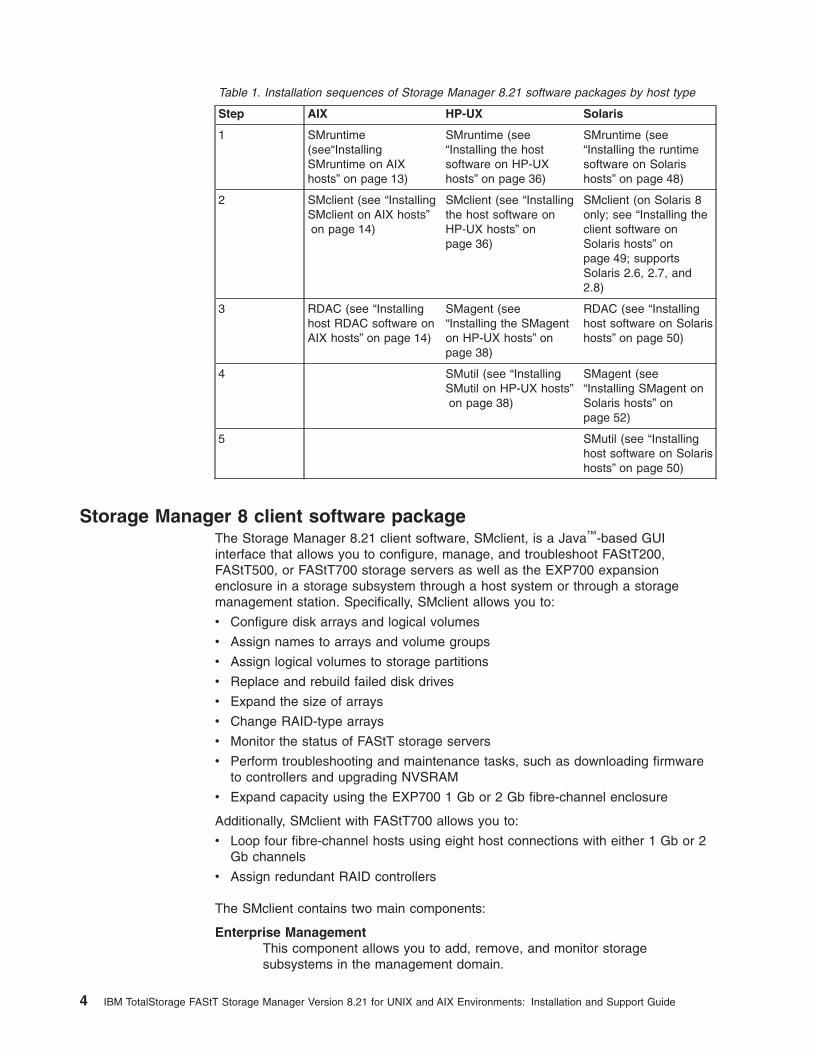
Table 1. Installation sequences of Storage Manager 8.21 software packages by host type
Step AIX HP-UX Solaris
1 SMruntime(see“InstallingSMruntime on AIXhosts” on page 13)
SMruntime (see“Installing the hostsoftware on HP-UXhosts” on page 36)
SMruntime (see“Installing the runtimesoftware on Solarishosts” on page 48)
2 SMclient (see “InstallingSMclient on AIX hosts”on page 14)
SMclient (see “Installingthe host software onHP-UX hosts” onpage 36)
SMclient (on Solaris 8only; see “Installing theclient software onSolaris hosts” onpage 49; supportsSolaris 2.6, 2.7, and2.8)
3 RDAC (see “Installinghost RDAC software onAIX hosts” on page 14)
SMagent (see“Installing the SMagenton HP-UX hosts” onpage 38)
RDAC (see “Installinghost software on Solarishosts” on page 50)
4 SMutil (see “InstallingSMutil on HP-UX hosts”on page 38)
SMagent (see“Installing SMagent onSolaris hosts” onpage 52)
5 SMutil (see “Installinghost software on Solarishosts” on page 50)
Storage Manager 8 client software packageThe Storage Manager 8.21 client software, SMclient, is a Java™-based GUIinterface that allows you to configure, manage, and troubleshoot FAStT200,FAStT500, or FAStT700 storage servers as well as the EXP700 expansionenclosure in a storage subsystem through a host system or through a storagemanagement station. Specifically, SMclient allows you to:
v Configure disk arrays and logical volumes
v Assign names to arrays and volume groups
v Assign logical volumes to storage partitions
v Replace and rebuild failed disk drives
v Expand the size of arrays
v Change RAID-type arrays
v Monitor the status of FAStT storage servers
v Perform troubleshooting and maintenance tasks, such as downloading firmwareto controllers and upgrading NVSRAM
v Expand capacity using the EXP700 1 Gb or 2 Gb fibre-channel enclosure
Additionally, SMclient with FAStT700 allows you to:
v Loop four fibre-channel hosts using eight host connections with either 1 Gb or 2Gb channels
v Assign redundant RAID controllers
The SMclient contains two main components:
Enterprise ManagementThis component allows you to add, remove, and monitor storagesubsystems in the management domain.
4 IBM TotalStorage FAStT Storage Manager Version 8.21 for UNIX and AIX Environments: Installation and Support Guide

Subsystem ManagementThis component allows you to manage the components of an individualstorage subsystem.
For more information about this software, see either Chapter 2, “Installing storagemanagement station software on AIX systems” on page 11, Chapter 3, “Installingstorage management station software on HP-UX systems” on page 35, orChapter 4, “Installing storage management station software on Solaris systems” onpage 47 and the IBM FAStT Storage Manager Concepts Guide.
Storage Manager 8 agent software packageThe Storage Manager 8.21 agent (SMagent) package contains the host-agentsoftware, which you can use on HP-UX host systems to manage storagesubsystems through the host fibre-channel connection. The host-agent softwaretakes requests from a storage management station that is connected to the hostthrough a network connection and passes the requests to the storage subsystemcontrollers through the fibre-channel I/O path.
For more information about managing storage subsystems through the host agent,see “Host-agent (in-band) management method” on page 6.
Storage Manager 8 utility software packageUse the Storage Manager 8.21 utility (SMutil) package to register and map newlogical drives to the operating system. Install SMutil on all HP-UX and Solaris hostsystems attached to a storage subsystem. The host computers are attached to thestorage subsystem through the fibre channel.
RDACAIX and Solaris host systems require an RDAC driver for fibre-channel pathredundancy. If a FAStT storage server has two controllers, and the operatingsystem does not support multipath I/O, then you can use the RDAC. The RDACmonitors I/O paths; if a component failure occurs in one of the fibre-channel paths,the RDAC reroutes all I/O to another path.
Note: The AIX RDAC driver files are not included on the Storage Manager 8.21installation CD; you must follow the instructions in “Installing host RDACsoftware on AIX hosts” on page 14 to download them from the appropriateWeb site.
Storage subsystem management methodsThe storage management software provides two methods for managing storagesubsystems:
v The host-agent (in-band) management method. In this method, you manage thestorage subsystems through the fibre-channel I/O path to the host.
Note: You cannot use this management method on AIX systems.
v The direct (out-of-band) management method. In this method, you manage thestorage subsystems directly over the network through the Ethernet connection toeach controller.
Chapter 1. Introduction 5

Host-agent (in-band) management methodWhen you use the host-agent (in-band) management method, you manage thestorage subsystems through the fibre-channel I/O path to the host. Themanagement information can be processed by the host or passed to the storagemanagement station through the network connection. Figure 1 shows the host-agent(in-band) management method.
Note: You cannot use the host-agent (in-band) management method on AIXsystems.
Managing storage subsystems using the host-agent (in-band) management methodhas the following advantages:
v You do not need to run Ethernet cables to the controllers.
v You do not need a Dynamic Host Configuration Protocol (DHCP) bootstrapprotocol (BOOTP) server to connect the storage subsystems to the network.
v You do not need to configure the controller network (described in Chapter 2,“Installing storage management station software on AIX systems” on page 11,Chapter 3, “Installing storage management station software on HP-UX systems”on page 35, or Chapter 4, “Installing storage management station software onSolaris systems” on page 47).
Network
Host computer
Controller
Controller
Controller
Controller
Fibre ChannelI/O path
Management station(one or more)
Running thehost-agent software
Storage subsystems
Note: The host can also act as amanagement station.
Storage subsystems
SJ000707
Figure 1. Host-agent (in-band) managed storage subsystems
6 IBM TotalStorage FAStT Storage Manager Version 8.21 for UNIX and AIX Environments: Installation and Support Guide

v When adding devices, you need to specify a host name or Internet Protocol (IP)address for the host only, not for the individual controllers in a storagesubsystem. Storage subsystems that are attached to the host are automaticallydiscovered.
Managing storage subsystems using the host-agent (in-band) management methodhas the following disadvantages:
v You are limited to configuring one less LUN than the maximum number allowedby the operating system and host adapter that you are using.
v The host-agent requires a special logical drive, called an access volume, tocommunicate with the controllers in the storage subsystem.
v If you are upgrading controllers from firmware version 3.x to version 4.x and yourhost system has already configured its maximum number of LUNs, you must giveup a LUN to be used as an access volume.
Important: The access volume uses one of the LUNs. If your host already has themaximum number of LUNs configured, either use the direct-management method orgive up a LUN for use as the access volume. For information about your specificconfiguration, see the appropriate chapter in this document for your operatingsystem environment.
Direct (out-of-band) management methodWhen you use the direct (out-of-band) management method, you manage storagesubsystems directly over the network through the Ethernet connection to eachcontroller. To manage the storage subsystem through the Ethernet connections, youmust define the IP address and host name for each controller and attach a cable tothe Ethernet ports on each of the storage subsystem controllers. Figure 2 on page 8shows the direct (out-of-band) management method.
Chapter 1. Introduction 7
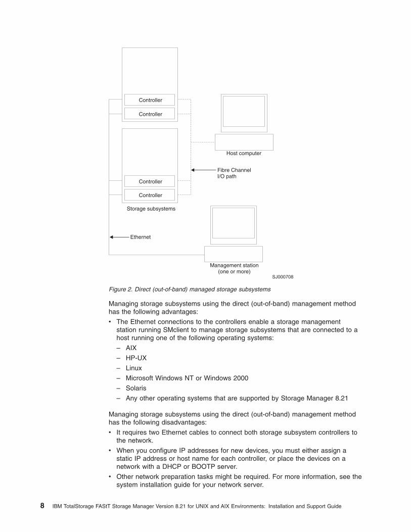
Managing storage subsystems using the direct (out-of-band) management methodhas the following advantages:
v The Ethernet connections to the controllers enable a storage managementstation running SMclient to manage storage subsystems that are connected to ahost running one of the following operating systems:
– AIX
– HP-UX
– Linux
– Microsoft Windows NT or Windows 2000
– Solaris
– Any other operating systems that are supported by Storage Manager 8.21
Managing storage subsystems using the direct (out-of-band) management methodhas the following disadvantages:
v It requires two Ethernet cables to connect both storage subsystem controllers tothe network.
v When you configure IP addresses for new devices, you must either assign astatic IP address or host name for each controller, or place the devices on anetwork with a DHCP or BOOTP server.
v Other network preparation tasks might be required. For more information, see thesystem installation guide for your network server.
Ethernet
Host computer
Fibre ChannelI/O path
Management station(one or more)
Controller
Controller
Controller
Controller
Storage subsystems
SJ000708
Figure 2. Direct (out-of-band) managed storage subsystems
8 IBM TotalStorage FAStT Storage Manager Version 8.21 for UNIX and AIX Environments: Installation and Support Guide
Operating system requirementsStorage Manager 8.21 supports the FAStT200, FAStT500, and FAStT700 storageservers in the following environments:
v IBM AIX 4.3.3 or 5.1 (see Appendix A, “AIX system requirements” on page 123)
v HP-UX 11.0 (32 bit or 64 bit), HP-UX 11.11, or HP-UX 11i (see Appendix B,“HP-UX system requirements” on page 125)
v Sun Solaris 2.6, 2.7, or 2.8 (see Appendix C, “Solaris system requirements” onpage 127)
Setting up IP addresses for FAStT storage controllersContact your network administrator to obtain the IP address and associated hostname for each controller in every storage subsystem on the network, and make anote of those values for reference.
To use the out-of-band management method without setting up a DHCP BOOTPserver, you must assign IP addresses to the FAStT controllers using CLI commandsthrough serial cables that are connected to a terminal emulator.
Complete the following steps to set up the FAStT controller IP addresses usingserial ports:
1. Stop all I/O to the FAStT controllers.
2. Connect a null modem serial cable from one of the controllers to a system witha terminal emulator available.
Note: Use HyperTerminal Private Edition Version 6.3 or later. Download thelatest version from the following web site:
www.hilgraeve.com
3. Open the HyperTerminal and from the menu bar click File —> Properties —>Configure. Choose the following settings:
v 115200 Baud
v 8 Data Bits
v 1 Stop Bit
v No parity
v XON/XOFF Flow Control
4. Connect to the FAStT storage server and send a break signal (Ctrl+Break formost emulators).
5. Repeat this step until the following message is displayed:
Press the space bar for baud rate within 5 seconds.
6. Press the space bar to ensure the correct baud rate setting.
7. Send another break signal; the following message is displayed:
Press within 5 seconds: ESC for SHELL, BREAK for baud rate.
8. Press Escape to access the shell of the controller.
9. Type the password: infiniti
10. Type netCfgShow to show the current network configuration.
Chapter 1. Introduction 9
Note: The default IP address settings when released from manufacture are asfollow:
v Controller A’s IP address = 192.168.10.101
v Controller B’s IP address = 192.168.10.102
v IP address mask = 255.255.255.0
11. Type netCfgSet to change the network configuration information.
Note: Press Enter to advance to the next field. Type the new IP address in theMy IP Address field.
12. Assign an IP address to the controller.
13. Disconnect from the first controller and connect to the second controller.
14. Repeat steps 1 on page 9 - 13 to assign the second IP address to the secondcontroller.
15. Restart the FAStT storage server by turning the controller unit off and on.
10 IBM TotalStorage FAStT Storage Manager Version 8.21 for UNIX and AIX Environments: Installation and Support Guide

Chapter 2. Installing storage management station software onAIX systems
This chapter provides the following specific information for AIX operating systems:
v Hardware and firmware requirements
– Creating a direct-attached configuration
– Creating a SAN-attached configuration
v AIX restrictions
v Client software installation
v Host software installation
v AIX configuration information
Hardware and firmware requirementsTable 2 lists the supported versions of hardware to use with Storage Manager 8.21.
Table 2. Supported versions of hardware for AIX systems
Product Name Model Product release and firmwareversion
IBM TotalStorage FAStT700 RAIDController Enclosure Unit
1742-1RU Appware 05.21.05.09,NVSRAM CNV1742R821NT012
IBM TotalStorage FAStT700EXP700 Storage Expansion Unit
1740-1RU ESM 9319
IBM FAStT500 RAID ControllerEnclosure Unit
3552-1RU Appware 05.21.05.09,NVSRAM CNV3552R821NT012
IBM FAStT500 EXP500 StorageExpansion Unit
3560-1RU ESM 9163
IBM FAStT200 RAID ControllerEnclosure Unit
3542-1RU andFC 2101
Snapware 05.20.12.09,NVSRAM CNV3542R821NT030
IBM FAStT200 RAID and StorageUnit, Double Controller
3542-2RU Snapware 05.20.12.09,NVSRAM CNV3542R821NT030
IBM HA Emulex LP7000 FC 6227 3.22A1
IBM HA Emulex LP9000 FC 6228 3.82A1
Brocade switch 2109-S082109-S16
2.6.0.e
Brocade switch 2109-F16 3.0.2f
Brocade switch 2109-M12 4.0.2
Brocade switch 3534-F08 3.0.2h
McData switch 2032-0642031-216,2031-2322032-140
4.01.00
INRANGE switch 2042-0012042-128
3.2.1
Read the README file that is shipped with the product and go to one of thefollowing Web sites to ensure that you have the latest versions of the firmware,NVSRAM, disk drive firmware, and host adapter device drivers:
© Copyright IBM Corp. 2002 11
www.pc.ibm.com/qtechinfo/MIGR-43793.html
Once there, follow the link to v8.21 information.
Creating a direct-attached configurationStorage Manager 8.21 supports FAStT200, FAStT500, and FAStT700 storageservers in direct-attached AIX (4.3.3 or 5.1) configurations.
To create a direct-attached configuration, you must ensure that:
v One or two AIX servers can be connected to the FAStT storage server.
– FAStT200 can support one AIX server.
– FAStT500 can support two AIX servers.
– FAStT700 can support two AIX servers.
v Two server FAStT500 or FAStT700 configurations require four host-sidemini-hubs, each with exactly one FC connection from each HBA to a mini-hub.
v There are two or four HBAs (FC 6227 or FC 6228) per FAStT storage server.Each pair must be configured to one FAStT partition.
v No external hubs are being used.
To set up a direct-attached configuration, follow these steps:
1. Connect the HBAs to each controller or mini-hub port of the FAStT storageserver.
2. Start the system.
3. Configure and verify the configuration as shown in the next sections.
Creating a SAN-attached configurationStorage Manager 8.21 supports FAStT200, FAStT500, and FAStT700 storageservers in a SAN environment through Fibre Channel switches in AIXconfigurations. To create a SAN-attached configuration, you must ensure that:
v Multiple Fibre Channel HBAs within the same server cannot “see” the sameFAStT controller port.
v The IBM Fibre Channel HBAs areisolated from each other if connected to thesame switch that is connected to the same FAStT controller port.
v If connecting through a single Fibre Channel switch, such as a IBM 2109-F16,each Fibre Channel HBA and controller port must be in it’s own fabric zone.
Consult the documentation provided by the switch manufacture for informationabout zoning for more information. Multiple FAStT devices can be configured tothe same set of Fibre Channel HBAs through a FC switch.
To set up a SAN-attached configuration, follow these steps:
1. Set the required zones on the Fibre Channel switch, if applicable.
2. Connect the HBAs to the switch or switches.
3. Connect the FAStT storage subsystems to the switch or switches.
4. Start the system.
5. Configure and verify the configuration as shown in the next sections.
12 IBM TotalStorage FAStT Storage Manager Version 8.21 for UNIX and AIX Environments: Installation and Support Guide
AIX restrictionsThe following restrictions apply to FAStT200, FAStT500, and FAStT700 storageservers:
v F-RAID Manager is not supported.
v The maximum number of partitions per AIX host, per FAStT storage server, istwo.
v Each AIX host can support two or four host bus adapters (FC 6227 or 6228) andup to two FAStT storage partitions, each requiring two host bus adapterconnections.
v Direct-attach configurations are restricted to single-initiator configurations only.Only one connection to each FAStT mini-hub is allowed.
v Single HBA configurations are not allowed. Each connection to a partition musthave two HBAs configured.
v Single-switch configurations are allowed, but each HBA and FAStT controllercombination must be in a separate SAN zone.
v All volumes that are configured for AIX must be mapped to an AIX host group.Connecting and configuring to volumes in the default host group is not allowed.See “Performing the initial configuration of storage subsystems on AIX hosts” onpage 15.
v Other storage devices, such as tape devices or other disk storage, must beconnected through separate HBAs and SAN zones.
Installing the host software on AIX hostsUse the following procedure to install the host software on an AIX storagemanagement station. Install the software in the following order:
1. SMruntime
2. SMclient
3. Update RDAC device driver
The FAStT client is dependent on SMruntime, which is a Java compiler for theSMclient and must be installed first.
PrerequisitesBefore installing the host software, ensure that the following conditions are met:
v The AIX host on which you are installing the SMruntime software meets theminimum hardware and software requirements described in “Hardware andfirmware requirements” on page 11 and “Software requirements” on page 123.
v The correct filesets are present on the system.
Note: If the filesets are not present, follow the instructions in “Installing hostRDAC software on AIX hosts” on page 14 to download them from theappropriate Web site.
– For a list of AIX 4.3.3 filesets, see Table 10 on page 123.
– For a list of AIX 5.1 filesets, see Table 11 on page 123.
Installing SMruntime on AIX hostsAdjust these instructions as required for your specific installation. No restart isrequired during the installation process.
Chapter 2. Installing storage management station software on AIX systems 13
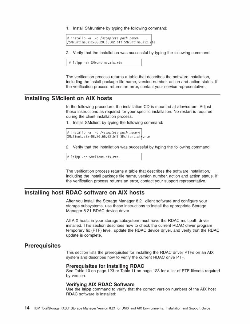
1. Install SMruntime by typing the following command:
# installp -a -d /<complete path name>/SMruntime.aix-08.20.65.02.bff SMruntime.aix.rte
2. Verify that the installation was successful by typing the following command:
# lslpp -ah SMruntime.aix.rte
The verification process returns a table that describes the software installation,including the install package file name, version number, action and action status. Ifthe verification process returns an error, contact your service representative.
Installing SMclient on AIX hostsIn the following procedure, the installation CD is mounted at /dev/cdrom. Adjustthese instructions as required for your specific installation. No restart is requiredduring the client installation process.
1. Install SMclient by typing the following command:
# installp -a -d /<complete path name>/SMclient.aix-08.20.65.02.bff SMclient.aix.rte
2. Verify that the installation was successful by typing the following command:
# lslpp -ah SMclient.aix.rte
The verification process returns a table that describes the software installation,including the install package file name, version number, action and action status. Ifthe verification process returns an error, contact your support representative.
Installing host RDAC software on AIX hostsAfter you install the Storage Manager 8.21 client software and configure yourstorage subsystems, use these instructions to install the appropriate StorageManager 8.21 RDAC device driver.
All AIX hosts in your storage subsystem must have the RDAC multipath driverinstalled. This section describes how to check the current RDAC driver programtemporary fix (PTF) level, update the RDAC device driver, and verify that the RDACupdate is complete.
PrerequisitesThis section lists the prerequisites for installing the RDAC driver PTFs on an AIXsystem and describes how to verify the current RDAC drive PTF.
Prerequisites for installing RDACSee Table 10 on page 123 or Table 11 on page 123 for a list of PTF filesets requiredby version.
Verifying AIX RDAC SoftwareUse the lslpp command to verify that the correct version numbers of the AIX hostRDAC software is installed:
14 IBM TotalStorage FAStT Storage Manager Version 8.21 for UNIX and AIX Environments: Installation and Support Guide

# lslpp -ah filename
Where filename is one of the required filesets listed in Table 10 on page 123 orTable 11 on page 123.
For example:
# lslpp -ah devices.fcp.disk.array.rte
Installing RDAC on AIX hostsComplete the following procedure to update the RDAC driver PTF(devices.fcp.disk.array.rte) on an AIX system. Repeat this procedure for all AIXsystems that are connected to the storage subsystem. You need not perform thisinstallation if you have verified that the version RDAC level is correct.
1. Go to one of the following Web sites:
ssddom02.storage.ibm.com/techsup/webnav.nsf/support/fastt200ssddom02.storage.ibm.com/techsup/webnav.nsf/support/fastt500ssddom02.storage.ibm.com/techsup/webnav.nsf/support/fastt700
2. Click Downloads in the downloads section of the Web page.
3. Scroll to the operating system-specific updates section of the Web page.
4. Follow the link to the appropriate sets of files for your operating system andfollow the installation instructions.
5. Verify that the correct version of the software was successfully installed bytyping the following command:
# lslpp -ah devices.fcp.disk.array.rte
The verification process returns a table that describes the software installation,including the installation package fileset name, version number, action, andaction status. If the verification process returns an error, contact your customerservice representative. If it does not return an error, then you are finishedinstalling the updated RDAC driver on this AIX system.
6. Configure the devices for the software changes to take effect by typing thefollowing command:
# cfgmgr -v
Performing the initial configuration of storage subsystems on AIXhosts
Complete the following procedure to configure Storage Manager 8.21 for an AIXsystem, which can be performed from Storage Manager client runing on an AIX ornon-AIX system.
1. To set up the storage subsystem for AIX and the AIX SMclient, the subsystemmust be physically configured for direct management through the Ethernetconnections on each controller. Install SMclient before configuring thesubsystem.
Note: See “Setting up IP addresses for FAStT storage controllers” on page 9 forinformation about assigning IP addresses to the controllers.
Chapter 2. Installing storage management station software on AIX systems 15

2. After the disk subsystem is configured on the network, start the SMclientsoftware on the host server by typing the following command:
# /usr/SMclient/SMclient
3. Complete the following steps to specify the IP addresses of the controllers.
a. In the Enterprise Management window, click Edit —> Add Device.
b. In the Add Device window, type the IP address of the first controller in thestorage subsystem and click Add.
c. Type the IP address of the second controller and click Add, and then clickClose.
The storage subsystem is shown as a direct network attachment. Double-clickStorage Subsystem to open the Subsystem Management window.
Updating FAStT firmware and NVSRAM1. In the Subsystem Management window, click View—> Storage Subsystem
Profile and review the summary portion of the output. Verify that the controllerfirmware and NVSRAM are at the correct versions. If they are not the correctversions, complete an upgrade, first the firmware, then NVSRAM.
Note: Even though concurrent firmware upgrades are supported, it isrecommend that I/O is quiesed before upgrading firmware. Concurrentupgrades of NVSRAM, however, are not supported.
2. Complete the following steps to upgrade the NVSRAM.
a. Mount and locate the NVSRAM file on the installation CD(/cdrom/NVSRAM/3542, /cdrom/NVSRAM/3552, or /cdrom/NVSRAM/1742), ordownload the correct version from the Web site. Place the file in adesignated directory on the host system.
b. In the Subsystem Management window, click Storage Subsystem —>Download —> NVSRAM.
c. Type or select the full pathname of the NVSRAM directory.
d. Double-click the NVSRAM filename or click OK to select the correct file.
e. Click Yes to start the download.
f. Verify that the NVSRAM was successfully installed.
3. After you ensure that all I/O to the controllers is stopped, complete the followingsteps to upgrade the controller firmware.
a. Mount and locate the firmware file on the installation CD(/cdrom/Firmware/3542, /cdrom/Firmware/3552 or /cdrom/Firmware/1742), ordownload the correct version from the Web site. Place the file in adesignated directory on the host system.
b. In the Subsystem Management window, click Storage Subsystem —>Download —> Firmware.
c. Type or select the full pathname of the firmware file.
d. Click OK to update both controllers.
e. Click Yes to start the download. A new window opens.
f. Close the Subsystem Management window and then reopen it to completethe firmware update.
g. Verify that the firmware was successfully installed.
16 IBM TotalStorage FAStT Storage Manager Version 8.21 for UNIX and AIX Environments: Installation and Support Guide

Setting up an AIX host group1. Click the Mappings View tab on the Subsystem Management window.
2. In the Mappings window, create a new host group by clicking Mappings —>Define —> Host Group.
3. Type the name of the new host group (for example, AIX). Click Add, and thenclick Close.
4. Highlight the new host group and click Mappings —> Define —> Host.
5. Define the new host. Type the name of the AIX host to which the storagesubsystem is attached.
a. Click Add, and then click Close.
b. Highlight the host that you just added and right-click Define New Host Port.
c. Select the desired host port for the first HBA, and then change the host typeto AIX and click Add.
Note: To verify that the host port matches the AIX host, run the lsdev -Ccadapter | grep fcs command. Identify the fcs by associating thenumber of host bus adapters (HBAs), then run the lscfg -vl fcs#|grep Network command. Verify that the number that displays underNetwork Address matches the host port number in the GUI. Repeatthis procedure for the second host port.
d. Choose the host port for the second HBA and click Add, and then clickClose.
AIX configuration informationThis section contains the following AIX configuration information:
v Viewing and setting attributes of the RDAC driver for AIX
v Identifying the controller ID numbers
v Identifying device names and bus numbers
v Identifying logical drives by operating system device names
v Redistributing volumes in case of failure
v Creating a direct-attached configuration
Viewing and setting attributes of the RDAC driver for AIXThe RDAC driver must be installed on all AIX hosts that will be attached to a FAStTstorage subsystem. The RDAC driver creates the following devices that representthe FAStT storage subsystem configuration:
dar The disk array router represents the entire array, including current anddeferred paths to all LUNs (hdisks on AIX).
dac The disk array controller devices represents a controllers within the storagesubsystem. There are two dacs in the storage subsystem.
hdisk These devices represent individual LUNs on the array.
When these devices are configured, the Object Data Manager (ODM) is updatedwith default parameters. In most cases and for most configurations, the defaultparameters are satisfactory. However, there are some parameters that may bemodified for maximum performance and availability. See “Recommended attributesettings” on page 24. Use the lsattr -El command to view attribute settings on anAIX system, as shown in the following examples.
Chapter 2. Installing storage management station software on AIX systems 17
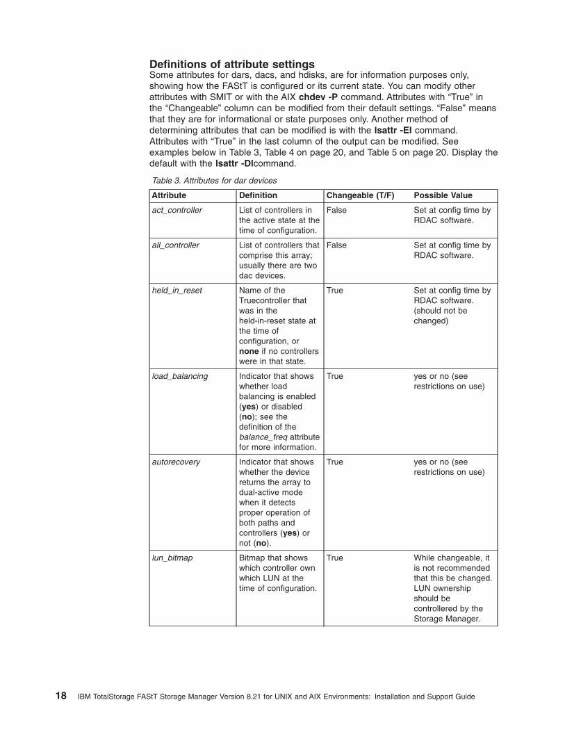
Definitions of attribute settingsSome attributes for dars, dacs, and hdisks, are for information purposes only,showing how the FAStT is configured or its current state. You can modify otherattributes with SMIT or with the AIX chdev -P command. Attributes with “True” inthe “Changeable” column can be modified from their default settings. “False” meansthat they are for informational or state purposes only. Another method ofdetermining attributes that can be modified is with the lsattr -El command.Attributes with “True” in the last column of the output can be modified. Seeexamples below in Table 3, Table 4 on page 20, and Table 5 on page 20. Display thedefault with the lsattr -Dlcommand.
Table 3. Attributes for dar devices
Attribute Definition Changeable (T/F) Possible Value
act_controller List of controllers inthe active state at thetime of configuration.
False Set at config time byRDAC software.
all_controller List of controllers thatcomprise this array;usually there are twodac devices.
False Set at config time byRDAC software.
held_in_reset Name of theTruecontroller thatwas in theheld-in-reset state atthe time ofconfiguration, ornone if no controllerswere in that state.
True Set at config time byRDAC software.(should not bechanged)
load_balancing Indicator that showswhether loadbalancing is enabled(yes) or disabled(no); see thedefinition of thebalance_freq attributefor more information.
True yes or no (seerestrictions on use)
autorecovery Indicator that showswhether the devicereturns the array todual-active modewhen it detectsproper operation ofboth paths andcontrollers (yes) ornot (no).
True yes or no (seerestrictions on use)
lun_bitmap Bitmap that showswhich controller ownwhich LUN at thetime of configuration.
True While changeable, itis not recommendedthat this be changed.LUN ownershipshould becontrollered by theStorage Manager.
18 IBM TotalStorage FAStT Storage Manager Version 8.21 for UNIX and AIX Environments: Installation and Support Guide
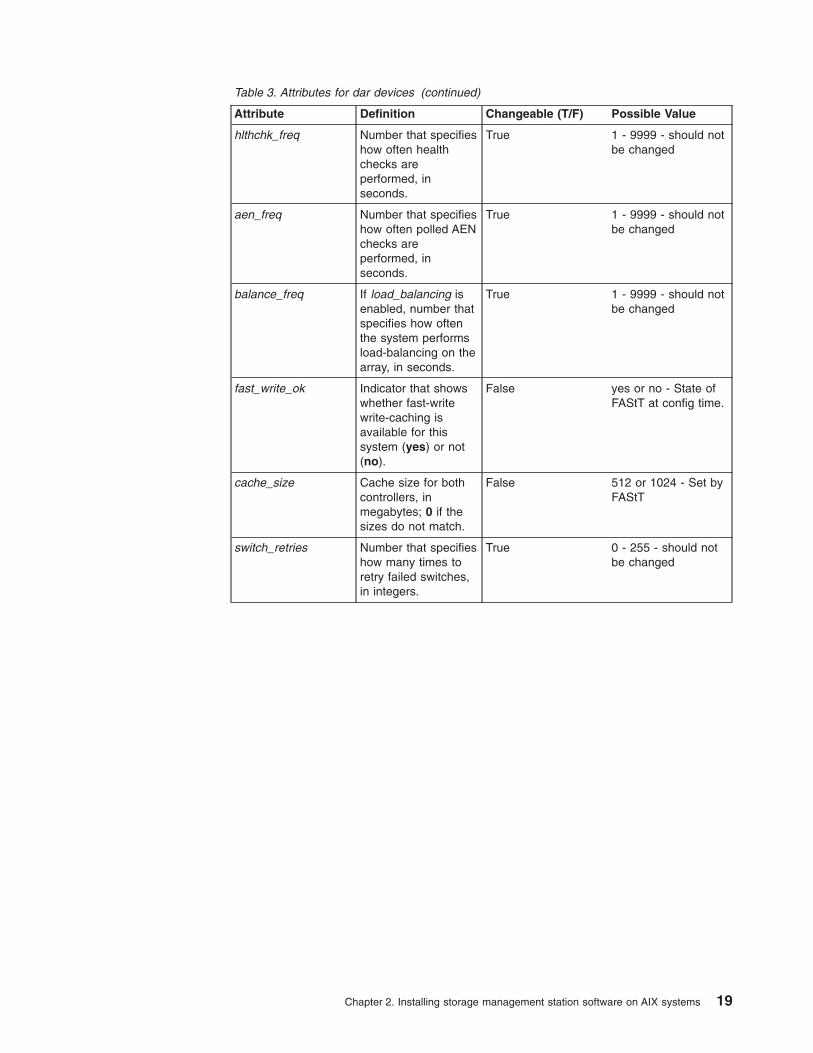
Table 3. Attributes for dar devices (continued)
Attribute Definition Changeable (T/F) Possible Value
hlthchk_freq Number that specifieshow often healthchecks areperformed, inseconds.
True 1 - 9999 - should notbe changed
aen_freq Number that specifieshow often polled AENchecks areperformed, inseconds.
True 1 - 9999 - should notbe changed
balance_freq If load_balancing isenabled, number thatspecifies how oftenthe system performsload-balancing on thearray, in seconds.
True 1 - 9999 - should notbe changed
fast_write_ok Indicator that showswhether fast-writewrite-caching isavailable for thissystem (yes) or not(no).
False yes or no - State ofFAStT at config time.
cache_size Cache size for bothcontrollers, inmegabytes; 0 if thesizes do not match.
False 512 or 1024 - Set byFAStT
switch_retries Number that specifieshow many times toretry failed switches,in integers.
True 0 - 255 - should notbe changed
Chapter 2. Installing storage management station software on AIX systems 19

Table 4. Attributes for dac devices
Attribute Definition Changeable (T/F) Possible Value
passive_control Indicator that showswhether thiscontroller was inpassive state at thetime of configuration(yes) or not (no).
False yes or no - State ofFAStT at config time.
alt_held_reset Indicator that showswhether the alternatecontroller was in theheld-in-reset state atthe time ofconfiguration (yes) ornot (no).
False yes or no - State ofFAStT at config time.
controller_SN Serial number of thiscontroller.
False Set by FAStT
ctrl_type Type of array thiscontroller belongs to;a value of 3542indicates FAStT200;a value of 3552indicates FAStT500;a value of 1742indicates FAStT700.
False 3542, 3552, 1742 -Set by FAStT
cache_size Cache size of thiscontroller, inmegabytes.
False 512, 1024 - Set byFAStT
scsi_id SCSI identifier of thiscontroller.
False Set by SAN, reportedby AIX.
lun_id Logical unit numberof this controller.
False Set by FAStT
utm_lun_id Logical unit numberof this controller, ornone if UTM (accessvolumes) is notenabled.
False 0 - 31. Set by FAStTStorage Manager.
location User-defined locationlabel for thiscontroller; the systemdoes not use thisvalue.
True Set by FAStT StorageManager
ww_name Fibre-channelworldwide name ofthis controller.
False Set by FAStT
GLM_type GLM type used forthis controller.
False high or low - Set byFAStT
Table 5. Attributes for hdisk devices
Attribute Definition Changeable (T/F) Possible Value
pvid AIX physical volumeidentifier, or none ifnot set.
False Set by AIX
20 IBM TotalStorage FAStT Storage Manager Version 8.21 for UNIX and AIX Environments: Installation and Support Guide

Table 5. Attributes for hdisk devices (continued)
Attribute Definition Changeable (T/F) Possible Value
q_type Queueing type forthis device; must beset to simple.
False Set by AIX, should be“simple”.
queue_depth Number that specifiesthe depth of thequeue based onsystem configuration;reduce this number ifthe array is returninga BUSY status on aconsistent basis.
True 1 - 64
reserve_lock Indicator that showswhether the fcparrayissues a SCSIRemove commandevery time a device isopened or when aTest Unit Readysequence is issuedby the driver (yes) ornot (no).
True yes or no
write_cache Indicator that showswhether write-cachingis enabled on thisdevice (yes) or not(no); see thedefinition of thecache_methodattribute for moreinformation.
True yes or no
size Size of this volume. False Set by FAStT
raid_level Number that specifiesthe RAID level of thisdevice.
False 0, 1, 3, 5 - Set byFAStT StorageManager
rw_timeout Number that specifiesthe read/write timeoutvalue for eachread/write commandto this array, inseconds; usually setto 30.
True 30 - 180 (should notbe changed fromdefault)
reassign_to Number that specifiesthe timeout value forFC reassignoperations, inseconds; usually setto 120.
True 0 - 1000 (should notbe changed fromdefault).
scsi_id SCSI identifier at thetime of configuration.
False Set by SAN, reportedby AIX.
lun_id Logical unit numberof this device.
False 0 - 31 - Set by FAStTStorage Manager
Chapter 2. Installing storage management station software on AIX systems 21

Table 5. Attributes for hdisk devices (continued)
Attribute Definition Changeable (T/F) Possible Value
cache_method If write_cache isenabled, thewrite-caching methodof this array; set toone of the following:
v default. Defaultmode; the word″default″ is notseen if write_cacheis set to yes.
v fast_write.Fast-write(battery-backed,mirroredwrite-cache) mode.
v fw_unavail.Fast-write modewas specified butcould not beenabled;write-caching is notin use.
v fast_load.Fast-load(non-battery-backed,non-mirroredwrite-cache) mode.
v fl_unavail.Fast-load modewas specified butcould not beenabled.
True default, fast_write,fast_load, fw_unavail,fl_unavail
prefetch_mult Number of blocks tobe prefetched intoread cache for eachblock read.
True 0 - 100
ieee_volname IEEE unique volumename identifier forthis volume.
False Set by FAStT
Viewing ODM attributes in AIXTo view the attributes for dars, dacs, and hdisks, use the AIX lsattr command. Thefollowing examples demonstrate using the lsattr -El command, which shows theattributes that are currently set on the system. To view the default settings, use the-Dl flag instead of -El. Then, I’d remove the subsection heading ″Using the lsattr-El command″.
This example shows the attribute settings for a disk array router (dar0):
22 IBM TotalStorage FAStT Storage Manager Version 8.21 for UNIX and AIX Environments: Installation and Support Guide
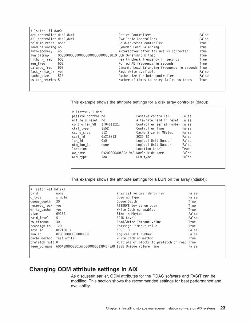
# lsattr -El dar0act_controller dac0,dac1 Active Controllers Falseall_controller dac0,dac1 Available Controllers Falseheld_in_reset none Held-in-reset controller Trueload_balancing no Dynamic Load Balancing Trueautorecovery no Autorecover after failure is corrected Truelun_bitmap 00000000000000000000000000001010 LUN Ownership bitmap Truehlthchk_freq 600 Health check frequency in seconds Trueaen_freq 600 Polled AE frequency in seconds Truebalance_freq 600 Dynamic Load Balancing frequency in seconds Truefast_write_ok yes Fast Write available Falsecache_size 512 Cache size for both controllers Falseswitch_retries 5 Number of times to retry failed switches True
This example shows the attribute settings for a disk array controller (dac0):
# lsattr -El dac0passive_control no Passive controller Falsealt_held_reset no Alternate held in reset Falsecontroller_SN 1T04611221 Controller serial number Falsectrl_type 3552 Controller Type Falsecache_size 512 Cache Size in MBytes Falsescsi_id 0x210013 SCSI ID Falselun_id 0x0 Logical Unit Number Falseutm_lun_id none Logical Unit Number Falselocation Location Label Trueww_name 0x200800a0b80c1948 World Wide Name FalseGLM_type low GLM type False
This example shows the attribute settings for a LUN on the array (hdisk4):
# lsattr -El hdisk4pvid none Physical volume identifier Falseq_type simple Queuing Type Falsequeue_depth 30 Queue Depth Truereserve_lock yes RESERVE device on open Truewrite_cache yes Write Caching enabled Truesize 69270 Size in Mbytes Falseraid_level 5 RAID Level Falserw_timeout 30 Read/Write Timeout value Truereassign_to 120 Reassign Timeout value Truescsi_id 0x210013 SCSI ID Falselun_id 0x0000000000000000 Logical Unit Number Falsecache_method fast_write Write Caching method Trueprefetch_mult 0 Multiple of blocks to prefetch on read Trueieee_volname 600A0B80000C1A70000000013B45FEA8 IEEE Unique volume name False
Changing ODM attribute settings in AIXAs discussed earlier, ODM attributes for the RDAC software and FAStT can bemodified. This section shows the recommended settings for best performance andavailability.
Chapter 2. Installing storage management station software on AIX systems 23

Recommended attribute settingsThis section lists the recommended attribute settings for hdisk devices and showshow to set them using the chdev -l command. To make the attribute changespermanent in the Customized Devices object class, use the -P option.
Some attributes can be changed from both the FAStT Storage Manager clientsoftware and through AIX. To make these changes permanent, the modificationsmust be made by changing the AIX ODM attribute. The specific attributes affectedare:
v hdisk:
– cache_write
– cache_method
– prefetch_mult
If the changes are made through the Storage Manager client software, they willoperate properly until you either reboot the host or restart cfgmgr. To make thechanges permanent, you must use SMIT or the chdev -P command.
Attention: Controller Cache mirroring should not be disabled while cache_write isenabled. If this condition exists, the RDAC Software will automatically re-enable itthe next time the system is reboot or when cfgmgr is run.
Restrictions for dar ODM attributes: The “autorecovery” attribute should only beset to yes in single initiator configurations. If other hosts are configured on thesame set of FC links, you should not enable this function.
The “load_balancing” attribute should only be set to yes in single-hostconfigurations.
Setting the Queue depth for hdisk devices: Setting the queue_depth attribute tothe appropriate value is important for system performance. For large FAStTconfigurations with many volumes and hosts attached, this is a critical setting forhigh availability. Improper setting of this attribute could result in the loss offilesystems and system panics.
Use the following formula to determine the maximum queue depth for your system:
512 / (number-of-hosts * LUNs-per-host )
For example, a system with four hosts, each with 32 LUNs (the maximum numberof LUNs per AIX host), would have a maximum queue depth of 4:
512 / ( 4 * 32 ) = 4
In this case, you would set the queue_depth attribute for hdiskX as follows:
# chdev -l hdiskX -a queue_depth=4 -P
Attention: If you do not set the queue depth to the proper level, you mightexperience loss of filesystems and system panics.
Verifying the installation and configuration of AIX hostsAfter you set the (Object Data Manager) ODM attributes, FAStT volumes andconfigurations, and before you mount your file systems and install your applications,
24 IBM TotalStorage FAStT Storage Manager Version 8.21 for UNIX and AIX Environments: Installation and Support Guide

use the following information to verify that all of your FAStT device names andpaths are correct and that AIX recognizes your dars, dacs, and hdisks.
Initial device identificationAfter the FAStT storage subsystem has been set up, volumes have been assignedto the host, and the RDAC driver has been installed, type the following command toprobe for the new devices:
# cfgmgr -v
Next, use the lsdev -Cc disk command to see if the RDAC software recognizeseach FAStT volume as a “3542 (200) Disk Array Device”, each FAStT500 volumeas a “3552 (500) Disk Array Device”, or each FAStT700 volume as a “1742 (700)Disk Array Device”. The following example shows the results of the command for aset of FAStT500 LUNs:
# lsdev -Cc diskhdisk0 Available 10-88-00-8,0 16 Bit LVD SCSI Disk Drivehdisk32 Available 31-08-01 3552 (500) Disk Array Devicehdisk33 Available 91-08-01 3552 (500) Disk Array Devicehdisk34 Available 31-08-01 3552 (500) Disk Array Devicehdisk35 Available 91-08-01 3552 (500) Disk Array Device
Identifying the controller ID numbersOne of the attributes listed by the lsattr -El command is the controller serial number(controller_SN) of that dac.
To display the FAStT Controller Properties window:
1. In the Physical view of the Subsystem Management window, select a controller.
2. Right-click Controller —> Properties.
Figure 3 on page 26 shows the Controller Properties window of the controller inslot A. This controller has a serial number of 1T04810361 and is represented bydac1.
# lsattr -El dac1passive_control no Passive controller Falsealt_held_reset no Alternate held in reset Falsecontroller_SN 1T14610048 Controller serial number Falsectrl_type 3552 Controller Type Falsecache_size 512 Cache Size in MBytes Falsescsi_id 0x210213 SCSI ID Falselun_id 0x0 Logical Unit Number Falseutm_lun_id none Logical Unit Number Falselocation Location Label Trueww_name 0x200600a0b80c213d World Wide Name FalseGLM_type low GLM type False
Chapter 2. Installing storage management station software on AIX systems 25

Identifying device names and bus numbersAfter the operating system device names are found, those names must becorrelated to the preferred and failover paths of the FAStT device, and then fromeach path to its associated logical drive. As mentioned earlier in this chapter, theRDAC software uses dars, dacs, and hdisks to represent the FAStT storagesubsystem. dars represent the “disk array routers”; dacs represent the “disk arraycontrollers”, and hdisks represent the “logical drives”, or FAStT “volumes”.
AIX provides the following commands to assist in determining the configuration ofthe FAStT storage subsystem:
lsdevDisplays devices and their characteristics. lsdev shows the state of the devicesat boot time, or the last time cfgmgr -v was run. -
lsattrDisplays device attributes and possible values. Attributes are only updated atboot time, or the last time cfgmgr -v was run.
fget_configDisplays controllers and hdisks associated with a specified FAStT (dar).fget_confg shows the current state and volume (hdisk) ownership.
SJ000709
Figure 3. Controller Properties window
26 IBM TotalStorage FAStT Storage Manager Version 8.21 for UNIX and AIX Environments: Installation and Support Guide

There are several ways to correlate a system’s configuration and monitor the stateof FAStT storage subsystems. The use of commands in validating configurations isillustrated in Figure 4.
lsdev commandThe following example uses the lsdev command to show the status of the dar,which represents a FAStT storage subsystem. This example shows dar as aMachine Type 3542, which is a FAStT200, and is in the “Available” state, which isthe state at the time when the device was last configured by AIX.
# lsdev -C |grep dar0dar0 Available 3542 (200) Disk Array Router
The following example uses the lsdev command to show the status of two dacs,which represent the FAStT storage subsystem controllers. As in the previousexample, this shows a FAStT200 in an “Available” state. The third column showsthe location code. In this example, each dac has its own location or ″path″, which isrepresented by the values 11-08-01 and 14-08-01. and . Each AIX system has itsown set of location codes that describe the internal path of that device, includingbus and host-adapter locations. See the service manual for your system type toidentify device locations.
# lsdev -C |grep dacdac0 Available 11-08-01 3542 (200) Disk Array Controllerdac1 Available 14-08-01 3542 (200) Disk Array Controller
The following example uses the lsdev command to show the status and locationcodes of eight FAStT200 hdisks. Notice that the location codes of the odd hdisks (1,3, 5, 7) correspond to the same location code of dac0 in the previous example, and
Switch 0
Switch 1
FC
SW
FC
SW
FAStT200(dar0)
CTLR A(dac0)
CTLR B(dac1)
SJ001037
Location: 11-08
Location: 14-08
AIX Serverfcs0
fcs1
LUNs
hdisk1
hdisk3
hdisk5
hdisk7
hdisk1
hdisk3
hdisk5
hdisk7
PreferredFailover
0
0
Figure 4. Use of commands applied to validating system configuration
Chapter 2. Installing storage management station software on AIX systems 27
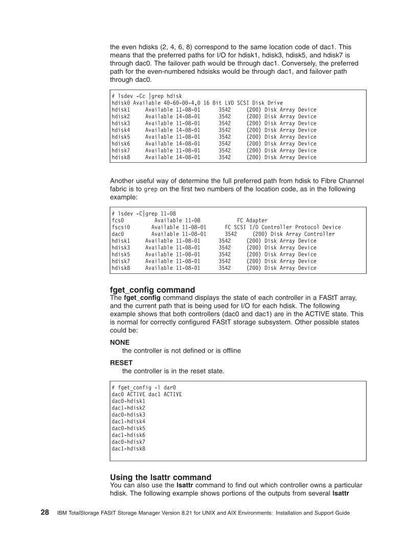
the even hdisks (2, 4, 6, 8) correspond to the same location code of dac1. Thismeans that the preferred paths for I/O for hdisk1, hdisk3, hdisk5, and hdisk7 isthrough dac0. The failover path would be through dac1. Conversely, the preferredpath for the even-numbered hdsisks would be through dac1, and failover paththrough dac0.
# lsdev -Cc |grep hdiskhdisk0 Available 40-60-00-4,0 16 Bit LVD SCSI Disk Drivehdisk1 Available 11-08-01 3542 (200) Disk Array Devicehdisk2 Available 14-08-01 3542 (200) Disk Array Devicehdisk3 Available 11-08-01 3542 (200) Disk Array Devicehdisk4 Available 14-08-01 3542 (200) Disk Array Devicehdisk5 Available 11-08-01 3542 (200) Disk Array Devicehdisk6 Available 14-08-01 3542 (200) Disk Array Devicehdisk7 Available 11-08-01 3542 (200) Disk Array Devicehdisk8 Available 14-08-01 3542 (200) Disk Array Device
Another useful way of determine the full preferred path from hdisk to Fibre Channelfabric is to grep on the first two numbers of the location code, as in the followingexample:
# lsdev -C|grep 11-08fcs0 Available 11-08 FC Adapterfscsi0 Available 11-08-01 FC SCSI I/O Controller Protocol Devicedac0 Available 11-08-01 3542 (200) Disk Array Controllerhdisk1 Available 11-08-01 3542 (200) Disk Array Devicehdisk3 Available 11-08-01 3542 (200) Disk Array Devicehdisk5 Available 11-08-01 3542 (200) Disk Array Devicehdisk7 Available 11-08-01 3542 (200) Disk Array Devicehdisk8 Available 11-08-01 3542 (200) Disk Array Device
fget_config commandThe fget_config command displays the state of each controller in a FAStT array,and the current path that is being used for I/O for each hdisk. The followingexample shows that both controllers (dac0 and dac1) are in the ACTIVE state. Thisis normal for correctly configured FAStT storage subsystem. Other possible statescould be:
NONEthe controller is not defined or is offline
RESETthe controller is in the reset state.
# fget_config -l dar0dac0 ACTIVE dac1 ACTIVEdac0-hdisk1dac1-hdisk2dac0-hdisk3dac1-hdisk4dac0-hdisk5dac1-hdisk6dac0-hdisk7dac1-hdisk8
Using the lsattr commandYou can also use the lsattr command to find out which controller owns a particularhdisk. The following example shows portions of the outputs from several lsattr
28 IBM TotalStorage FAStT Storage Manager Version 8.21 for UNIX and AIX Environments: Installation and Support Guide

commands.
# lsattr -El dac0passive_control no Passive controller Falsealt_held_reset no Alternate held in reset Falsecontroller_SN 1T01710113 Controller serial number Falsectrl_type 3552 Controller Type Falsecache_size 512 Cache Size in MBytes Falsescsi_id 0x11100 SCSI ID Falselun_id 0x0 Logical Unit Number False
# lsattr -El dac1passive_control no Passive controller Falsealt_held_reset no Alternate held in reset Falsecontroller_SN 1T03910039 Controller serial number Falsectrl_type 3552 Controller Type Falsecache_size 512 Cache Size in MBytes Falsescsi_id 0x11000 SCSI ID Falselun_id 0x0 Logical Unit Number False
# lsattr -El hdisk1----------- Parts removed:scsi_id 0x11100 SCSI ID Falselun_id 0x0000000000000000 Logical Unit Number Falsecache_method fast_write Write Caching method True
In the example, hdisk1 belongs to the controller represented by dac0. The hdisk hasthe same SCSI ID as the controller (dac) that owns it.
Identifying logical drives by operating system device namesThe lsattr command provides detailed information about a volume, includinginformation that allows you to map the system device name to the logical volume onthe FAStT storage subsystem.
For example, if you use the lsattr command on the LUN named hdisk4, it providesthe following information: it is a 6 GB LUN of type RAID, with a LUN ID of 2, and anIEEE volume name of 600A0B80000C1E6300000033BB39927 (see the followingexample). You can make a quick identification by locating the LUN ID on the farright side of the Mappings Viewtab.
# lsattr -El hdisk4pvid none Physical volume identifier Falseq_type simple Queuing Type Falsequeue_depth 30 Queue Depth Truereserve_lock yes RESERVE device on open Truewrite_cache yes Write Caching enabled Truesize 6062 Size in Mbytes Falseraid_level 0 RAID Level Falserw_timeout 30 Read/Write Timeout value Truereassign_to 120 Reassign Timeout value Truescsi_id 0x11000 SCSI ID Falselun_id 0x0002000000000000 Logical Unit Number Falsecache_method fast_write Write Caching method Trueprefetch_mult 0 Multiple of blocks to prefetch on read Trueieee_volname 600A0B80000C1E63000000033BB39927 IEEE Unique volume name False
Chapter 2. Installing storage management station software on AIX systems 29

You can make a more exact correlation using the distinctive ieee_volname attribute.The value of this attribute on the AIX host is the same as the Unique Logical DriveIdentifier on the FAStT storage subsystem. The ieee_volname and Unique LogicalDrive Identifier can be found in the Change Mappings window, which is shown inFigure 5. (Click the Mappings view tab. Select Logical Drive Name. Right clickand select Change Mappings.)
Another way to identify the system disk name based on the logical volume name isby using the Logical Drive Property window. Open this window by clicking theStorage Management window and right-clicking Logical Drive Name —>Properties. Look for the World-wide name, Capacity, and RAID level properties,as shown in Figure 6 on page 31.
The following example shows a portion of the output of the lsattr command forhdisk20. Notice that the ieee_volname and lun_id attributes have the same valuesas the World-wide name and Subsystem ID (SSID) properties shown in Figure 6on page 31, respectively.
# lsattr -El hdisk20write_cache yes Write Caching enabled Truesize 9216 Size in Mbytes Falseraid_level 5 RAID Level Falsescsi_id 0x210513 SCSI ID Falselun_id 0x0012000000000000 Logical Unit Number Falsecache_method fast_write Write Caching method Trueprefetch_mult 0 Multiple of blocks to prefetch on read Trueieee_volname 600A0B80000C1E63000000163BB39B7C IEEE Unique volume name False
SJ000712
Figure 5. Change Mappings window
30 IBM TotalStorage FAStT Storage Manager Version 8.21 for UNIX and AIX Environments: Installation and Support Guide

Disk array errorsThis section shows a list of possible Disk Array errors that could be reported in theAIX error log. Should an error occur, check your Storage Manager Major Event Log(MEL) to see if there is any correlation between the the host, SAN, and FAStTstorage subsystem. You may also need to validate your configuration or replacedefective hardware to correct the situation.
v FCP_ARRAY_ERR1 ARRAY OPERATION ERROR
– A permanent hardware error involving the disk array media.
v FCP_ARRAY_ERR2 ARRAY OPERATION ERROR
– A permanent hardware error.
v FCP_ARRAY_ERR3 ARRAY OPERATION ERROR
– A permanent error detected by the array adapter.
v FCP_ARRAY_ERR4 ARRAY OPERATION ERROR
– A temporary error within the array, communications, adapter, etc.
v FCP_ARRAY_ERR5 UNDETERMINED ERROR
v FCP_ARRAY_ERR6 SUBSYSTEM COMPONENT FAILURE
– A degradation condition has occurred other than a disk drive.
v FCP_ARRAY_ERR7 CONTROLLER HEALTH CHECK FAILURE
– A health check on the passive controller has failed.
v FCP_ARRAY_ERR8 ARRAY CONTROLLER SWITCH
– A condition has occurred which caused an array controller switch to occur.
SJ000713
Figure 6. Volume Properties window
Chapter 2. Installing storage management station software on AIX systems 31
v FCP_ARRAY_ERR9 ARRAY CONTROLLER SWITCH FAILURE
– An array controller switch has failed.
v FCP_ARRAY_ERR10 ARRAY CONFIGURATION CHANGED
– A logical unit has been moved from one controller to the other (most likely viathe action of an alternate host).
v FCP_ARRAY_ERR11 IMPROPER DRIVE TYPE FOR DUAL ACTIVE MODE
– This error should not be possible on the 2102 array, and exists for historicreasons only. FCP_ARRAY_ERR11 may be reused for a different error in thefuture.
v FCP_ARRAY_ERR12 POLLED AEN FAILURE
– An automatic error notification has failed.
v FCP_ARRAY_ERR13 ARRAY INTER-CONTROLLER COMMUNICATIONFAILURE
v FCP_ARRAY_ERR14 ARRAY DRIVE FAILURE
v FCP_ARRAY_ERR15 CACHE BATTERY LOW/DATA LOSS POSSIBLE
– Note if a controller card is replaced, it is likely that the cache batteries will beflat. It can take two days for the cache batteries to be fully recharged. Duringthis time errors will be logged in the errorlog. Do not replace the controller.
v FCP_ARRAY_ERR16 CACHE BATTERY CHARGE BELOW 87.5%
– Note if a controller card is replaced, it is likely that the cache batteries will beflat. It can take two days for the cache batteries to be fully recharged. Duringthis time errors will be logged in the errorlog. Do not replace the controller.
v FCP_ARRAY_ERR17 WORLD-WIDE NAME CHANGED
– A controller has changed world wide names (most likely either it was replacedwithout placing it in reset first, or cabling was changed so that a differentcontroller with the same SCSI id is on the loop).
v FCP_ARRAY_ERR18 RESERVATION CONFLICT
– An operation failed because the disk array volume (LUN) is reserved byanother host.
Redistributing volumes in case of failureIf a failure occurs that initiates a controller failover, follow this procedure toredistribute logical drives to their preferred paths.
1. Repair or replace any faulty components.
2. Complete these steps to mark the failed controller active.
a. Go to the Subsystem Management window.
b. Right-click controller A or controller B, and then click Change —> ModeActive.
3. Redistribute volumes to their preferred paths by clicking SubsystemManagement —> Storage Subsystem —> Redistribute Logical Drive.
4. Use the fget_config command to verify the active paths, as shown in thisexample:
32 IBM TotalStorage FAStT Storage Manager Version 8.21 for UNIX and AIX Environments: Installation and Support Guide

# fget_config -l dar0dac0 ACTIVE dac1 ACTIVEdac0-hdisk1dac0-hdisk2dac0-hdisk3dac1-hdisk4dac1-hdisk5dac1-hdisk6dac1-hdisk7dac0-hdisk8
Chapter 2. Installing storage management station software on AIX systems 33

34 IBM TotalStorage FAStT Storage Manager Version 8.21 for UNIX and AIX Environments: Installation and Support Guide
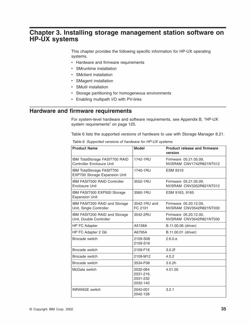
Chapter 3. Installing storage management station software onHP-UX systems
This chapter provides the following specific information for HP-UX operatingsystems.
v Hardware and firmware requirements
v SMruntime installation
v SMclient installation
v SMagent installation
v SMutil installation
v Storage partitioning for homogeneous environments
v Enabling multipath I/O with PV-links
Hardware and firmware requirementsFor system-level hardware and software requirements, see Appendix B, “HP-UXsystem requirements” on page 125.
Table 6 lists the supported versions of hardware to use with Storage Manager 8.21.
Table 6. Supported versions of hardware for HP-UX systems
Product Name Model Product release and firmwareversion
IBM TotalStorage FAStT700 RAIDController Enclosure Unit
1742-1RU Firmware 05.21.05.09,NVSRAM CNV1742R821NT012
IBM TotalStorage FAStT700EXP700 Storage Expansion Unit
1740-1RU ESM 9319
IBM FAStT500 RAID ControllerEnclosure Unit
3552-1RU Firmware 05.21.05.09,NVSRAM CNV3352R821NT012
IBM FAStT500 EXP500 StorageExpansion Unit
3560-1RU ESM 9163, 9165
IBM FAStT200 RAID and StorageUnit, Single Controller
3542-1RU andFC 2101
Firmware 05.20.12.09,NVSRAM CNV3542R821NT030
IBM FAStT200 RAID and StorageUnit, Double Controller
3542-2RU Firmware 05.20.12.00,NVSRAM CNV3542R821NT030
HP FC Adapter A5158A B.11.00.06 (driver)
HP FC Adapter 2 Gb A6795A B.11.00.01 (driver)
Brocade switch 2109-S082109-S16
2.6.0.e
Brocade switch 2109-F16 3.0.2f
Brocade switch 2109-M12 4.0.2
Brocade switch 3534-F08 3.0.2h
McData switch 2032-0642031-216,2031-2322032-140
4.01.00
INRANGE switch 2042-0012042-128
3.2.1
© Copyright IBM Corp. 2002 35
If the controllers are shipped with a firmware release prior to version 05.20.08.00and an NVSRAM release prior to version CNV3542R821NT016 (for FAStT200storage servers), or a firmware release prior to version 05.21.01.01 and anNVSRAM release prior to version CNV3552R821NT007 (for FAStT500 storageservers), or a firmware release prior to version 05.21.01.01 and an NVSRAMrelease prior to version CNV1742R821NT007 (for FAStT700 storage servers), theymust be upgraded. Read the readme file that is shipped with the product and go toone of the following Web sites to ensure that you have the latest versions of thefirmware, NVSRAM, disk drive firmware, and host adapter device drivers:
ssddom02.storage.ibm.com/techsup/webnav.nsf/support/fastt200ssddom02.storage.ibm.com/techsup/webnav.nsf/support/fastt500ssddom02.storage.ibm.com/techsup/webnav.nsf/support/fastt700
Installing the host software on HP-UX hostsThe host software for HP-UX consists of the following three packages:
1. FAStT client (SMclient)
2. FAStT host agent (SMagent)
3. FAStT utilities (SMutil)
All three packages are dependent on SMruntime, which is a Java compiler for theSMclient, SMagent, and SMutil. The host software is dependent on Java RuntimeEnvironment, if you do not install SMruntime you will receive errors during thesoftware install analysis phase.
Use the following procedure to install the host software on an HP-UX storagemanagement station or on an HP-UX host acting as a storage management station.Install the software in the following order:
1. SMruntime
2. SMclient
3. SMagent
4. SMutil
PrerequisitesBefore installing the host software, ensure that the following conditions are met:
v This is the HP 9000-series server that you identified as the storage managementstation.
v This machine meets the minimum hardware and software requirements describedin Appendix B, “HP-UX system requirements” on page 125.
v Neither the SMruntime, SMclient, SMagent, or SMutil is installed on the host andyou are ready to install it on this machine.
Installing SMruntime on HP-UX hostsIn the following procedure, the installation CD is mounted at /cdrom. Adjust theseinstructions as required for your specific installation. No restart is required duringthe SMruntime installation process.
1. Insert the HP-UX installation CD in the CD-ROM drive.
2. Start the installation process by typing the following command:
# mount -o cdcase -F cdfs /<put device pathname here> /cdrom# swinstall -s /cdrom/HP-UX/HPruntime_0804500
36 IBM TotalStorage FAStT Storage Manager Version 8.21 for UNIX and AIX Environments: Installation and Support Guide

The Software Selection window opens and displays this message:
SMruntime
3. Select SMruntime.
4. Select Actions—> Mark for installation.
5. Select Actions —> Install (Analysis).
6. Click OK when the analysis is finished.
7. In the confirmation window, click Yes to start the installation.
8. When the application is finished, click Done in the Installation window andclose the application.
Note: You must exit the sw install command before running the swverifycommand to verify the installation.
9. Verify that the installation was successful by typing the following command:
# swverify -v SMruntime
If no failure is reported, go to step 10. If a failure is reported, follow theinstructions in the /var/adm/sw/swagent.log file.
10. You have completed the SMruntime installation of this HP-UX storagemanagement station.
Installing the SMclient on HP-UX hostsIn the following procedure, the installation CD is mounted at /cdrom. Adjust theseinstructions as required for your specific installation. No restart is required duringthe SMclient installation process.
1. Start the installation process by typing the following command:
# swinstall -s /cdrom/HP-UX/SMclient-HP-081G500
The Software Selection window opens and displays the following message:
SMclient
2. Select SMclient.
3. Select Actions —> Mark for installation.
4. Select Actions —> Install (Analysis)
5. Click OK when the analysis is finished.
6. In the Confirmation window, click Yes to start the installation.
7. When the application is finished, click Done in the Installation window and closethe application.
Note: You must exit the sw install command before running the swverifycommand to verify installation.
8. Verify that the installation was successful by typing the following command:
# swverify -v SMclient
If no failures is reported, go to step 9 on page 38. If a failure is reported, followthe instructions in the /var/adm/sw/swutil.log file.
Chapter 3. Installing storage management station software on HP-UX systems 37
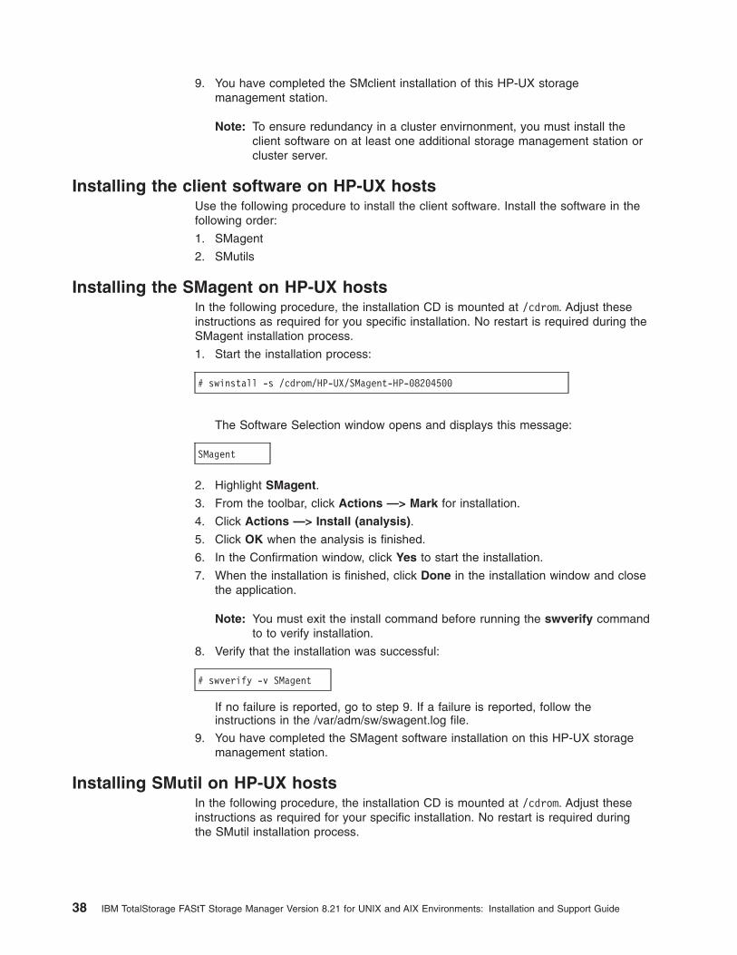
9. You have completed the SMclient installation of this HP-UX storagemanagement station.
Note: To ensure redundancy in a cluster envirnonment, you must install theclient software on at least one additional storage management station orcluster server.
Installing the client software on HP-UX hostsUse the following procedure to install the client software. Install the software in thefollowing order:
1. SMagent
2. SMutils
Installing the SMagent on HP-UX hostsIn the following procedure, the installation CD is mounted at /cdrom. Adjust theseinstructions as required for you specific installation. No restart is required during theSMagent installation process.
1. Start the installation process:
# swinstall -s /cdrom/HP-UX/SMagent-HP-08204500
The Software Selection window opens and displays this message:
SMagent
2. Highlight SMagent.
3. From the toolbar, click Actions —> Mark for installation.
4. Click Actions —> Install (analysis).
5. Click OK when the analysis is finished.
6. In the Confirmation window, click Yes to start the installation.
7. When the installation is finished, click Done in the installation window and closethe application.
Note: You must exit the install command before running the swverify commandto to verify installation.
8. Verify that the installation was successful:
# swverify -v SMagent
If no failure is reported, go to step 9. If a failure is reported, follow theinstructions in the /var/adm/sw/swagent.log file.
9. You have completed the SMagent software installation on this HP-UX storagemanagement station.
Installing SMutil on HP-UX hostsIn the following procedure, the installation CD is mounted at /cdrom. Adjust theseinstructions as required for your specific installation. No restart is required duringthe SMutil installation process.
38 IBM TotalStorage FAStT Storage Manager Version 8.21 for UNIX and AIX Environments: Installation and Support Guide
1. Start the installation process:
# swinstall -s /cdrom/HP-UX/SMutil_08204500
The Software Selection window opens and displays this message:
SMutil
2. Highlight SMutils.
3. Select Actions —> Mark for Installation.
4. Select Actions —> Install (Analysis).
5. Click OK when the analysis is finished.
6. In the conformation window, click Yes to start the installation.
7. When the application is finished, click Done in the installation window and closethe application.
Note: You must exit the install command before running the swverify commandto verify installation.
8. Verify that the installation was successful:
# swverify -v SMutil
If no failure is reported, go to step 9. If a failure is reported, follow theinstructions in the /var/adm/sw/swagent.log file.
9. You have completed the SMutil installation of this HP-UX storage managementstation.
Configuring storage and partitioning for heterogeneous environmentsAfter you install Storage Manager 8.21 software you need to configure thesubsystem. System configuration includes configuring logical drives through theSubsystem Management window of the SMclient application.
For more information about configuring storage see IBM TotalStorage FAStT700and Copy Services, an IBM Redbook publication.
See “Configuring storage subsystems” on page 60 for additional information aboutstorage configuration.
Read the following before continuing:
v All FAStT storage servers ship with NVSRAM configured for Windows NT hostsand have an access volume set to LUN 31.
v AVT/ADT is enabled by default; leave it in that state for HP-UX hosts.
v If the controllers are shipped with a firmware release prior to version 05.20.08.00and an NVSRAM release prior to version NV3542R810N016 (for FAStT200storage servers), or NV3552R821NT007 (for FAStT500 storage servers), or afirmware release prior to 05.21.01.01 and an NVSRAM release prior toCNV1742R821NT007 (for FAStT700 storage servers), they must be upgraded.Read the readme file that is shipped with the product and go to one of thefollowing Web sites to ensure that you have the latest versions of the firmwareand the NVSRAM:
Chapter 3. Installing storage management station software on HP-UX systems 39

www.storage.ibm.com/fast200/supserver.htmwww.storage.ibm.com/fast500/supserver.htmwww.storage.ibm.com/fast700/supserver.htm
Note: The versions of firmware and NVSRAM that ship with this product can belater releases than those described in this document.
Configuring storageComplete the following procedure to configure Storage Manager 8.21 for an HP-UXsystem.
1. To set up the storage subsystem for HP-UX, the subsystem must be physicallyconfigured, at least initially, for direct management through the Ethernetconnections on each controller as well as through the fibre-channel connection.Install the Storage Manager 8.21 software (SMruntime, SMclient, SMagent, andSMutil) before configuring the subsystem.
2. After the disk subsystem is configured on the network, type the followingcommand to run the SMclient software on either the host server, if it is on thesame network as the storage subsystem, or on another machine in the networkthat has the Storage Manager 8.21 software installed:
# SMclient
3. Complete the following steps to specify the IP addresses of the controllers.
a. In the Enterprise Management window, click Edit —> Add Device.
b. In the Add Device window, type the IP address of the first controller in thestorage subsystem and click Add.
c. Type the IP address of the second controller and click Add, and then clickClose.
4. In the Subsystem Management window, click Storage Subsystem —> Profileand review the summary portion of the output.
Read the readme file that is shipped with the product and go to one of thefollowing Web sites to ensure that you have the latest versions of the firmwareand the NVSRAM:
www.storage.ibm.com/fast200/supserver.htmwww.storage.ibm.com/fast500/supserver.htmwww.storage.ibm.com/fast700/supserver.htm
5. Complete the following steps to upgrade the NVSRAM.
a. Rescan the storage subsystem, and then click Manage the Device to returnto the Subsystem Management window.
b. Click Storage Subsystem —> Download —> NVSRAM.
c. In the NVSRAM window, go to the directory where the latest NVSRAM fileresides.
d. Type or select the full pathname of the NVSRAM file, and then click Update—> OK.
If required, the host restart process starts after the storage subsystem has beenturned off.
6. Complete the following steps to upgrade the firmware.
a. Click Storage Subsystem —> Download —> Firmware.
b. Go to the directory where the firmware resides.
40 IBM TotalStorage FAStT Storage Manager Version 8.21 for UNIX and AIX Environments: Installation and Support Guide

c. Type or select the full pathname of the firmware file, and then click Update—> OK.
The firmware is downloaded to the controllers. When the download is finished,the storage subsystem becomes unresponsive and you are returned to theEnterprise Management window.
7. Type the following command to restart the host:
# reboot
Partitioning storage
Note: Before you partition the storage, identify the worldwide port name for each ofyour HBAs. Look for the worldwide port name for the HBA and write downthe number for future reference. Use the following command to find yourHBAs listed in the dev directory as td0, td1, and so on, where X in thefollowing example represents the td number.
#cd /dev/td#tdutil /dev/td<X>
1. Click the Mappings View tab on the Subsystem Management window.
2. In the Mappings window, create a new host group by clicking Mappings —>Define —> Host Group.
3. Type the name of the new host group (for example, HP-UX). Click Add, and thenclick Close.
4. Select the new host group and click Mappings —> Define —> Host.
5. Define the new host. Type the name of the HP-UX host to which the storagesubsystem is attached.
a. Click Add, and then click Close.
b. Highlight the host that you just added and right-click Define New Host Port.
Note: You might be required to restart the host if you cannot see theWWPN for your HBAs. Restarting causes the system to log into theswitch.
c. Select the desired host port for the first HBA, and then change the host typeto HP-UX and click Add.
d. Choose the host port for the second HBA and click Add, and then clickClose.
Enabling multipath I/O with PV-linksIf the HP-UX system is attached with two host bus adapters to the FAStT storageserver, you can establish redundant access to storage by using physical volumelinks (PV-links), a feature of the HP-UX operating system. PV-links achieve accessredundancy by using devices with both primary and secondary paths to the samedevice. Use the following procedure to establish redundant access to storage byusing PV-links.
1. Run the hot_add command from HP-UX at the shell prompt. This commandupdates any new devices that are created or added. A dump is generated.When the hot_add utility runs, each new logical drive that is created in theSubsystem Management window represents a disk device to the operatingsystem.
Chapter 3. Installing storage management station software on HP-UX systems 41

#hot_add
2. Run the SMdevices command. The system provides a dump similar to theexample in Figure 7. Notice that every logical drive or device and accesslogical unit number (LUN) is listed twice, because you have two paths to eachlogical drive.
#SMdevices
3. Determine the primary and alternate path for each logical drive. A part of theWWN of each logical drive is unique for each controller in the FAStT storage
IBM FAStT Storage Manager Devices, Version 08.21.45.00Built Wed Mar 20 00:58:59 GMT+00:00 2002(C) Copyright International Business Machines Corporation, 2002Licensed Material - Program Property of IBM. All rights reserved.
/dev/rdsk/c28t0d2 [Storage Subsystem 700var201, Logical Drive hp_1, LUN 1,Logical Drive WWN <600a0b8000075a54000000803d2c6de6>, Preferred Path(Controller-A): In Use]
/dev/rdsk/c28t0d3 [Storage Subsystem 700var201, Logical Drive hp_2, LUN 2,Logical Drive WWN <600a0b8000075a540000006d3d2c6d9f>, Alternate Path(Controller-A): In Use]
/dev/rdsk/c28t0d4 [Storage Subsystem 700var201, Logical Drive hp_3, LUN 3,Logical Drive WWN <600a0b8000075a54000000813d2c6df4>, Preferred Path(Controller-A): In Use]
/dev/rdsk/cc28t0d5 [Storage Subsystem 700var201, Logical Drive hp_4, LUN 4,Logical Drive WWN <600a0b8000075a540000006e3d2c6da9>, Alternate Path(Controller-A): In Use]
/dev/rdsk/c28t3d7 [Storage Subsystem 700var201, Logical Drive Access, LUN 31,Logical Drive WWN <600a0b8000075a540000000200000000>]
/dev/rdsk/c30t0d2 [Storage Subsystem 700var201, Logical Drive hp_1, LUN 1,Logical Drive WWN <600a0b8000075e60000000803d2c6de6>, Preferred Path(Controller-A): In Use]
/dev/rdsk/c30t0d3 [Storage Subsystem 700var201, Logical Drive hp_2, LUN 2,Logical Drive WWN <600a0b8000075e600000006d3d2c6d9f>, Alternate Path(Controller-A): In Use]
/dev/rdsk/c30t0d4 [Storage Subsystem 700var201, Logical Drive hp_3, LUN 3,Logical Drive WWN <600a0b8000075e60000000813d2c6df4>, Preferred Path(Controller-A): In Use]
/dev/rdsk/c30t0d5 [Storage Subsystem 700var201, Logical Drive hp_4, LUN 4,Logical Drive WWN <600a0b8000075e600000006e3d2c6da9>, Aternate Path(Controller-A): In Use]
/dev/rdsk/c30t3d7 [Storage Subsystem 700var201, Logical Drive Access, LUN 31,Logical Drive WWN<600a0b8000075e600000000200000000>]
Figure 7. Device names
42 IBM TotalStorage FAStT Storage Manager Version 8.21 for UNIX and AIX Environments: Installation and Support Guide
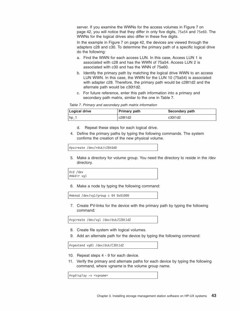
server. If you examine the WWNs for the access volumes in Figure 7 onpage 42, you will notice that they differ in only five digits, 75a54 and 75e60. TheWWNs for the logical drives also differ in these five digits.
In the example in Figure 7 on page 42, the devices are viewed through theadapters c28 and c30. To determine the primary path of a specific logical drivedo the following:
a. Find the WWN for each access LUN. In this case, Access LUN 1 isassociated with c28 and has the WWN of 75a54. Access LUN 2 isassociated with c30 and has the WNN of 75e60.
b. Identify the primary path by matching the logical drive WWN to an accessLUN WWN. In this case, the WWN for the LUN 10 (75a54) is associatedwith adapter c28. Therefore, the primary path would be c28t1d2 and thealternate path would be c30t1d2.
c. For future reference, enter this path information into a primary andsecondary path matrix, similar to the one in Table 7.
Table 7. Primary and secondary path matrix information
Logical drive Primary path Secondary path
hp_1 c28t1d2 c30t1d2
d. Repeat these steps for each logical drive.
4. Define the primary paths by typing the following commands. The systemconfirms the creation of the new physical volume.
#pvcreate /dev/rdsk/c28t0d0
5. Make a directory for volume group. You need the directory to reside in the /devdirectory.
#cd /dev#mkdir vg1
6. Make a node by typing the following command:
#mknod /dev/vg1/group c 64 0x01000
7. Create PV-links for the device with the primary path by typing the followingcommand:
#vgcreate /dev/vg1 /dev/dsk/C28t1d2
8. Create file system with logical volumes.
9. Add an alternate path for the device by typing the following command:
#vgextend vg01 /dev/dsk/C30t1d2
10. Repeat steps 4 - 9 for each device.
11. Verify the primary and alternate paths for each device by typing the followingcommand, where vgname is the volume group name.
#vgdisplay -v <vgname>
Chapter 3. Installing storage management station software on HP-UX systems 43
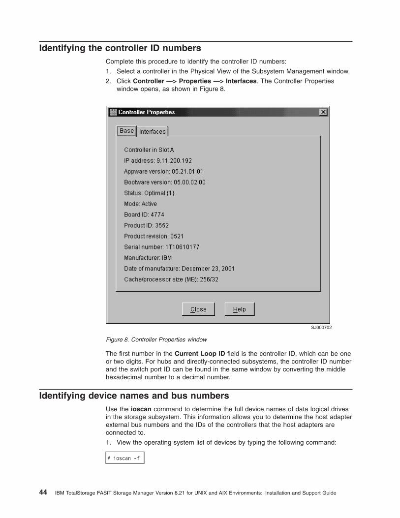
Identifying the controller ID numbersComplete this procedure to identify the controller ID numbers:
1. Select a controller in the Physical View of the Subsystem Management window.
2. Click Controller —> Properties —> Interfaces. The Controller Propertieswindow opens, as shown in Figure 8.
The first number in the Current Loop ID field is the controller ID, which can be oneor two digits. For hubs and directly-connected subsystems, the controller ID numberand the switch port ID can be found in the same window by converting the middlehexadecimal number to a decimal number.
Identifying device names and bus numbersUse the ioscan command to determine the full device names of data logical drivesin the storage subsystem. This information allows you to determine the host adapterexternal bus numbers and the IDs of the controllers that the host adapters areconnected to.
1. View the operating system list of devices by typing the following command:
# ioscan -f
SJ000702
Figure 8. Controller Properties window
44 IBM TotalStorage FAStT Storage Manager Version 8.21 for UNIX and AIX Environments: Installation and Support Guide

2. The identification information for every device is displayed. See Figure 9.
3. Examine the information. LUN numbers range from 0 - 7 and target addressesfrom 0 - 3.
Device names have the following format: c<x>t<y>d<z> where:
<x>Represents the controller ID number
<y>Represents the target address
<z>Represents the LUN number
For example, disk 130 in Figure 9 has a device name of c2t0d0.
4. Determine the entries for the logical drives using the controller ID and LUNnumbers. Find the ext_bus row above the logical drive listing and note the busnumber in the I column.
5. For each storage subsystem, use the Mappings window (see Figure 10 onpage 46). Click the Mappings View tab in Subsystem Management window.
v Select the storage subsystem node in the Topology View to see a list of alllogical drives in the Mappings View.
v Use the LUN numbers in the Mappings View to associate the logical driveswith their device names.
Class
bcbcfcStoragelanStorage Cntlfcp
disk
ext_bustargetdisk
targetdisk
===================================================================================I
010
0
35
239130
39131
H/W Path
88/12
8/12.8
8/12.8.0.2.0.0.7
8/12.8.0.2.0.08/12.8.0.2.0.08/12.8.0.2.0.0.0
8/12.8.0.2.0.18/12.8.0.2.0.1.0
Driver
rootcciofcT1
fcp
sdisk
fcpdevtgtsdisk
tgtsdisk
S/W State
CLAIMEDCLAIMEDCLAIMED
CLAIMED
CLAIMED
CLAIMEDCLAIMED
CLAIMEDCLAIMED
CLAIMEDCLAIMED
H/W Type
BUS_NEXUSBUS_NEXUSINTERFACE
INTERFACE
INTERFACE
DEVICE
INTERFACEDEVICEDEVICE
DEVICEDEVICE
Description
I/O AdapterHP Fibre Channel
HP Fibre Channel
FCP Protocol Adapter
IBM Universal Xport
FCP Device Interface
IBM INF-01-00
IBM INF-01-00
SJ000701
External bus number ofthe host adapter
Controller IDnumber
Target address
LUN number
Switch portID number
Figure 9. Device identification information
Chapter 3. Installing storage management station software on HP-UX systems 45

SJ000703
Figure 10. Mappings window
46 IBM TotalStorage FAStT Storage Manager Version 8.21 for UNIX and AIX Environments: Installation and Support Guide

Chapter 4. Installing storage management station software onSolaris systems
This chapter provides the following specific information for Solaris operatingsystems.
v Hardware and firmware requirements
v Runtime software installation
v Client software installation
v Host software installation
v Configuration information
Hardware and firmware requirementsTable 8 lists the supported versions of hardware to use with Storage Manager 8.21.
Table 8. Supported versions of hardware for Solaris systems
Product Name Model Product release and firmwareversion
IBM TotalStorage FAStT700 RAIDController Enclosure Unit
1742-1RU Firmware 05.21.05.09,NVSRAM CNV1742R821NT012
IBM TotalStorage FAStT700EXP700 Storage Expansion Unit
1740-1RU ESM 9319
IBM FAStT500 RAID ControllerEnclosure Unit
3552-1RU Firmware 05.21.05.09,NVSRAM CNV3352R821NT012
IBM FAStT500 EXP500 StorageExpansion Unit
3560-1RU ESM 9163, 9165
IBM FAStT200 RAID and StorageUnit, Single Controller
3542-1RU andFC 2101
Firmware 05.20.12.09,NVSRAM CNV3542R821NT030
IBM FAStT200 RAID and StorageUnit, Double Controller
3542-2RU Firmware 05.20.12.00,NVSRAM CNV3542R821NT030
JNI FC Adapter FC64-1063 fcaw2.5.18.pkg
JNI FC Adapter FCE-1063 S-bus64 bit
JNIC.pkg, version 4.1.1.1
JNI FC Adapter FCE-1473 S-bus64 bit
JNIC146x.pkg, version 5.1.2
JNI FC Adapter FCE-6410-N 33Mhz
JNIC.pkg, version 4.1.1.1
JNI FC Adapter FCE-6460-PCI 64bit
JNIC146x.pkg, version 5.1.2
JNI FC Adapter FCE2-1063S-bus 64 bit
JNIC.pkg, version 4.1.1.1
JNI FC Adapter FCE2-6412 66Mhz 64 bit
JNIC.pkg, version 4.1.1.1
JNI FC Adapter FCI-1063 fca-pci.2.5.18.pkg
Brocade switch 2109-S082109-S16
2.6.0.e
Brocade switch 2109-F16 3.0.2f
© Copyright IBM Corp. 2002 47

Table 8. Supported versions of hardware for Solaris systems (continued)
Product Name Model Product release and firmwareversion
Brocade switch 2109-M16 4.0.0.a
Brocade switch 3534-F08 3.0.2h
McData switch 2032-0642031-216,2031-2322032-140
4.01.00
INRANGE switch 2042-0012042-128
3.2.1
Read the readme that is shipped with the product and go to one of the followingWeb sites to ensure that you have the latest versions of the firmware, NVSRAM,disk drive firmware, and host adapter device drivers:
ssddom02.storage.ibm.com/techsup/webnav.nsf/support/fastt200ssddom02.storage.ibm.com/techsup/webnav.nsf/support/fastt500ssddom02.storage.ibm.com/techsup/webnav.nsf/support/fastt700
For system-level hardware and software requirements, see Appendix C, “Solarissystem requirements” on page 127.
Installing the runtime software on Solaris hostsUse the following procedure to install the runtime software (SMruntime) on a Solarisstorage management station.
PrerequisitesBefore installing the runtime software, ensure that the following conditions are met:
v This is the SUN SPARCstation workstation that you have identified as thestorage management station.
v This machine is running Solaris 2.6, 2.7, or 8 and meets the minimum hardwareand software requirements described in Appendix C, “Solaris systemrequirements” on page 127.
v SMruntime is not installed and you are ready to install it on this machine.
ProcedureIn the following procedure, the installation CD is mounted at /cdrom/sm821. Adjustthese instructions as required for your specific installation location. No restart isrequired during the client installation process.
1. Insert the Solaris installation CD in the CD-ROM drive.
2. Start the installation process by typing the following command:
pkgadd -d /cdrom/SM821/SUN_SParc/SM8runtime-Sparc<filename>.pkg
Information about packages that can be installed in the specified directory isdisplayed on the command line. The following is an example of what you mightsee displayed.
48 IBM TotalStorage FAStT Storage Manager Version 8.21 for UNIX and AIX Environments: Installation and Support Guide
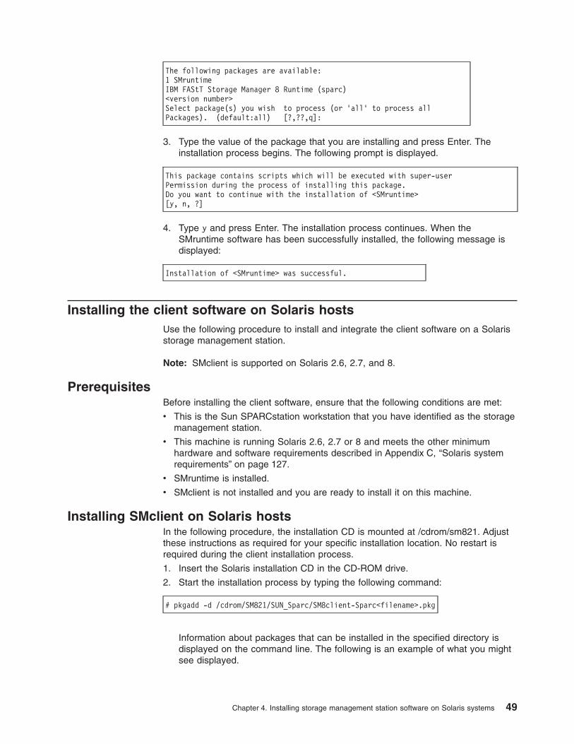
The following packages are available:1 SMruntimeIBM FAStT Storage Manager 8 Runtime (sparc)<version number>Select package(s) you wish to process (or ’all’ to process allPackages). (default:all) [?,??,q]:
3. Type the value of the package that you are installing and press Enter. Theinstallation process begins. The following prompt is displayed.
This package contains scripts which will be executed with super-userPermission during the process of installing this package.Do you want to continue with the installation of <SMruntime>[y, n, ?]
4. Type y and press Enter. The installation process continues. When theSMruntime software has been successfully installed, the following message isdisplayed:
Installation of <SMruntime> was successful.
Installing the client software on Solaris hostsUse the following procedure to install and integrate the client software on a Solarisstorage management station.
Note: SMclient is supported on Solaris 2.6, 2.7, and 8.
PrerequisitesBefore installing the client software, ensure that the following conditions are met:
v This is the Sun SPARCstation workstation that you have identified as the storagemanagement station.
v This machine is running Solaris 2.6, 2.7 or 8 and meets the other minimumhardware and software requirements described in Appendix C, “Solaris systemrequirements” on page 127.
v SMruntime is installed.
v SMclient is not installed and you are ready to install it on this machine.
Installing SMclient on Solaris hostsIn the following procedure, the installation CD is mounted at /cdrom/sm821. Adjustthese instructions as required for your specific installation location. No restart isrequired during the client installation process.
1. Insert the Solaris installation CD in the CD-ROM drive.
2. Start the installation process by typing the following command:
# pkgadd -d /cdrom/SM821/SUN_Sparc/SM8client-Sparc<filename>.pkg
Information about packages that can be installed in the specified directory isdisplayed on the command line. The following is an example of what you mightsee displayed.
Chapter 4. Installing storage management station software on Solaris systems 49
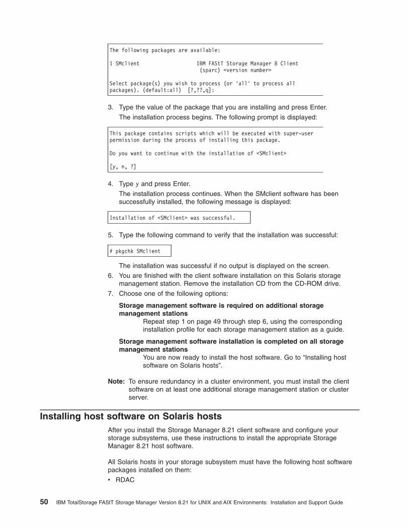
The following packages are available:
1 SMclient IBM FAStT Storage Manager 8 Client(sparc) <version number>
Select package(s) you wish to process (or ’all’ to process allpackages). (default:all) [?,??,q]:
3. Type the value of the package that you are installing and press Enter.
The installation process begins. The following prompt is displayed:
This package contains scripts which will be executed with super-userpermission during the process of installing this package.
Do you want to continue with the installation of <SMclient>
[y, n, ?]
4. Type y and press Enter.
The installation process continues. When the SMclient software has beensuccessfully installed, the following message is displayed:
Installation of <SMclient> was successful.
5. Type the following command to verify that the installation was successful:
# pkgchk SMclient
The installation was successful if no output is displayed on the screen.
6. You are finished with the client software installation on this Solaris storagemanagement station. Remove the installation CD from the CD-ROM drive.
7. Choose one of the following options:
Storage management software is required on additional storagemanagement stations
Repeat step 1 on page 49 through step 6, using the correspondinginstallation profile for each storage management station as a guide.
Storage management software installation is completed on all storagemanagement stations
You are now ready to install the host software. Go to “Installing hostsoftware on Solaris hosts”.
Note: To ensure redundancy in a cluster environment, you must install the clientsoftware on at least one additional storage management station or clusterserver.
Installing host software on Solaris hostsAfter you install the Storage Manager 8.21 client software and configure yourstorage subsystems, use these instructions to install the appropriate StorageManager 8.21 host software.
All Solaris hosts in your storage subsystem must have the following host softwarepackages installed on them:
v RDAC
50 IBM TotalStorage FAStT Storage Manager Version 8.21 for UNIX and AIX Environments: Installation and Support Guide

v SMagent
v SMutil
This section contains the procedure for installing the software.
PrerequisitesBefore installing the host software, ensure that the following conditions are met:
v This is the Sun SPARCstation workstation that you have identified as the storagemanagement station.
v This machine is running Solaris 2.6, 7, or 8, and meets the minimum hardwareand software requirements described in Appendix C, “Solaris systemrequirements” on page 127.
v The RDAC, SMagent, and SMutil software packages are not installed and youare ready to install them on this machine.
Note: If you plan to run Storage Manager 8.21 in an environment that includesstorage arrays that you are not upgrading to 8.21, you must upgrade yourexisting storage manager to at least version 6.22. The Storage Manager 8.21RDAC package replaces the version 6.22 RDAC files and is shared byversion 6.22 and version 8.21 of the storage management software.
See the Storage Manager 6.x installation instructions for information aboutuninstalling the software.
Installing RDAC on Solaris hostsIn the following procedure, the installation CD is mounted at /cdrom/SM821. Adjustthese instructions as required for your specific installation location.
1. Insert the Solaris installation CD in the CD-ROM drive.
2. Type the following command to start installing the RDAC package:
# pkgadd -d /cdrom/SM821/SUN_Sparc/SM8rdac-Sparc-<filename>.pkg
The installation process begins.
Information about packages that can be installed in the specified directory isdisplayed on the command line. The following is an example of what you mightsee displayed.
The following packages are available:
1 RDAC Redundant Disk Array Controller(sparc) <version number>
Select package(s) you wish to process (or ’all’ to process allpackages). (default:all) [?,??,q]:
3. Type the value of the package you are installing and press Enter.
The installation process begins.
4. The software automatically checks for package conflicts. If any conflicts aredetected, a message is displayed indicating that some files are already installedand are in use by another package.
Chapter 4. Installing storage management station software on Solaris systems 51

The following prompt is displayed:
Do you want to install these conflicting files [y, n, ?]
Type y and press Enter.
5. The following prompt is displayed:
This package contains scripts which will be executed with super-userpermission during the process of installing this package.
Do you want to continue with the installation of <RDAC>
[y, n, ?]
Type y and press Enter.
The installation process continues.
6. When the RDAC package has been successfully installed, the followingmessage is displayed:
Installation of <RDAC> was successful.
Note: Make sure that the variables in the configuration files for your JNIadapter cards have been set to the correct values. For information aboutthese configuration files and their variables, see “Variable settings for JNIadapter cards” on page 56.
Installing SMagent on Solaris hostsPerform the folowing procedure to install SMagent:
1. Type the following command to start installing the SMagent package.
pkgadd -d /cdrom/SM821/SUN_SParc/SM8agent-Sparc-<filename>.pkg
The installation process begins.
Information about packages that can be installed in the specified directory isdisplayed on the command line. The following is an example of what you mightsee displayed.
The following packages are available:
1 SMagent IBM FAStT Storage Manager 8 Agent(sparc) <version number>
Select package(s) you wish to process (or ’all’ to process allpackages). (default:all) [?,??,q]:
2. Type the value of the package that you are installing and press Enter.
The installation process begins. The following prompt is displayed.
This package contains scripts which will be executed with super-userPermission during the process of installing this package.Do you want to continue with the installation of <SMagent>[y n, ?]
52 IBM TotalStorage FAStT Storage Manager Version 8.21 for UNIX and AIX Environments: Installation and Support Guide
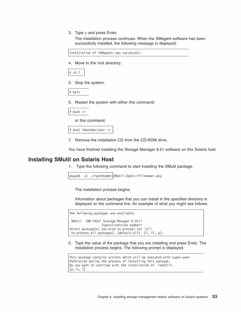
3. Type y and press Enter.
The installation process continues. When the SMagent software has beensuccessfully installed, the following message is displayed:
Installation of <SMagent> was successful.
4. Move to the root directory:
# cd /
5. Stop the system:
# halt
6. Restart the system with either this command:
# boot -r
or this command:
# boot <bootdevices> -r
7. Remove the installation CD from the CD-ROM drive.
You have finished installing the Storage Manager 8.21 software on this Solaris host.
Installing SMutil on Solaris Host1. Type the following command to start installing the SMutil package.
pkgadd -d ./<pathname>/SMutil-Sparc-<filename>.pkg
The installation process begins.
Information about packages that you can install in the specified directory isdisplayed on the command line. An example of what you might see follows.
The following packages are available:
SMutil IBM FAStT Storage Manager 8 Util(sparc)<version number>
Select package(s) you wish to process (or ’all’to process all packages). (default:all) [?, ??, q]:
2. Type the value of the package that you are installing and press Enter. Theinstallation process begins. The following prompt is displayed.
This package contains scripts which will be executed with super-userPermission during the process of installing this package.Do you want to continue with the installation of <smutil>[y, n, ?]
Chapter 4. Installing storage management station software on Solaris systems 53

3. Type y and press Enter.
Installation of <smutil> was successful.
Performing the initial configuration of storage subsystems on Solarishosts
Read the following before continuing:
v All FAStT storage servers ship with NVSRAM configured for Windows NT hostsand have an access volume set to LUN 31. This should not present anyproblems for Solaris in recognizing the storage subsystem.
v If the controllers are shipped with a firmware release prior to version 05.20.08.00and an NVSRAM release prior to version CNV3542R821NT016 (for FAStT200storage servers), or a firmware release prior to version 05.21.01.01 and anNVSRAM release prior to version CNV3552R821NT007 (for FAStT500 storageservers), or a firmware release prior to version 05.21.01.01 and an NVSRAMrelease prior to version CNV1742R821NT007 (for FAStT700 storage servers), theymust be upgraded.
Read the README file that is shipped with the product and go to one of thefollowing Web sites to ensure that you have the latest versions of the firmwareand the NVSRAM:
www.storage.ibm.com/fast200/supserver.htmwww.storage.ibm.com/fast500/supserver.htmwww.storage.ibm.com/fast700/supserver.htm
Note: Versions of firmware and NVSRAM that ship with this product can be laterreleases than those described in this document.
If you do not have the latest versions, download them and continue with step 1. Ifthe version numbers are current, then go to step 6.
Complete the following procedure to configure Storage Manager 8.21 for a Solarissystem:
1. Upgrade the NVSRAM and then upgrade the firmware. In the SubsystemManagement window, click Storage Subsystem —> Download —> NVSRAM.
2. In the NVSRAM window, go to the directory where the latest NVSRAM fileresides.
3. Type or select the full pathname of the NVSRAM file, and then click Update —>OK.
4. Click Storage Subsystem —> Download —> Firmware.
5. Type or select the full pathname of the firmware file, and then click Update —>OK.
The firmware is downloaded to the controllers. When the download is finished,the firmware becomes unresponsive and you are returned to the EnterpriseManagement window.
6. Rescan the storage subsystem, and then click Manage the Device to return tothe Subsystem Management window.
7. In the Subsystem Management window, click the Mappings View tab.
8. In the Mappings window, create a new host group by clicking Mappings —>Define —> Host Group.
54 IBM TotalStorage FAStT Storage Manager Version 8.21 for UNIX and AIX Environments: Installation and Support Guide

9. Type the name of the new host group (for example, Solaris). Click Add, andthen click Close.
10. Select the new host group and click Mappings —> Define —> Host.
11. Define the new host. Type the name of the Solaris host to which the storagesubsystem is attached.
a. Click Add, and then click Close.
b. Right-click the host that you just added and select Define New Host Port.
c. Select the desired host port for the first HBA, and then change the hosttype to Solaris and click Add.
d. Choose the host port for the second HBA and click Add, and then clickClose.
e. To view the added LUNs, click the host group, and then click Mappings—> Define —> Define Additional Mapping.
f. Type the following command to run the hot_add utility:
# /etc/raid/bin/hot_add
For information about the output of the utility, see “Default partitioning forSolaris devices”.
g. Click File —> Exit.
h. Obtain the device name for each volume (or LUN) by typing the followingcommand:
# format
The SMclient is now able to connect to the storage subsystem.
Uninstalling Storage Manager 8.21 softwareWhen you uninstall SMruntime, RDAC, SMclient, SMagent, or SMutil software, thedirectory /var/opt/SM8 might not be removed. Delete this directory to ensure a cleaninstallation of the new software.
Default partitioning for Solaris devicesAfter you install the Storage Manager 8.21 software and configure the subsystemsand logical drives through the Subsystem Management window of the SMclientapplication, run the /etc/raid/bin/hot_add utility from a shell prompt. (For additionalinformation about the hot_add utility see the applicable man page.)
When the hot_add utility is run, each logical drive that is created in the SubsystemManager presents a disk device to the operating system. The devices have thefollowing naming convention:
/dev/[r]dsk/c<X>t<X>d<X>s<X>| | | | || | | | s=slice| | | d=drive| | t=target| c=controllerdisk subdirectory
Chapter 4. Installing storage management station software on Solaris systems 55

where X represents a number. The number following the slice (s) represents thepartition on the disk and can be from 0 - 7.
You can overwrite disk information by using partitions or slices 0 - 2; this results inan inability to mount a disk. For this reason, do not use slices 0, 1, or 2. Usingthese slices may cause unpredictable results. Mount file systems only on slices 3,4, 5, 6, or 7 on the devices that are derived from the logical drives on the storagesubsystem.
Configuring JNI host bus adapter cardsThe RDAC software includes the following shell scripts that you can use toconfigure JNI cards for use with connections through fibre-channel switches:
v For FCI-1063 cards, /etc/raid/bin/genfcaconf
v For all jnic.conf and jnic.146x.conf cards, /etc/raid/bin/genjniconf
v For FC64-1063 and all other cards, /etc/raid/bin/genscsiconf, which calls otherscripts as appropriate
For additional information, see the man pages for each script.
Variable settings for JNI adapter cardsTable 9 lists the configuration file for each JNI adapter driver package.
Table 9. JNI adapter configuration files
JNI HBA model numbers JNI adapter driver package Configuration file
FC64-1063-N fcaw2.5.18.pkg /kernel/drv/fcaw.conf
FCI-1063-N fca-pci.2.5.18.pkg /kernel/drv/fca-pci.conf
FCE2-1063, FCE2-1063,FCE-6410, FCE2-6412
JNIC.pkg, version 4.1.1.1 /kernel/drv/jnic.conf
FCE-1473, FCE-6412 (2 Gb) JNIC146x.pkg, version 5.1.2 /kernel/drv/jnic146x.conf
Note: See information located in Appendix E, “JNI Host Bus Adapter settings” onpage 131 to verify your HBA settings.
Ensure that the configuration file for your adapter meets the following criteria:
v The FCLoopEnabled and FcFabricEnabled variables must be set appropriatelyfor your configuration; see the configuration file for details.
v If the fca_nport variable is in the file, set it to 1.
v If the ip-disable variable is in the file, set it to 1.
v In fca*.conf files, set BusyRetryDelay to 5000.
v In fca*.conf files, set scsi_probe_delay to 5000.
v In fca*.conf files, set link_recovery_delay to 1000.
v The lines that contain these variables must be uncommented and set to thespecified values:
– failover or FailoverDelay, set to 30
– JniCreationDelay, set to 10
– def_wwnn_binding, remove the dollar-sign character ($) from the line
– def_wwpn_binding
– def_hba_binding
56 IBM TotalStorage FAStT Storage Manager Version 8.21 for UNIX and AIX Environments: Installation and Support Guide

Note:
1. def_hba_binding is for fca.pci.conf and fcaw.conf
2. When the RDAC software is installed, the def_hba_binding variablein the fca-pci.conf and fcaw.conf files is set to nonjni. This is thecorrect behavior.
3. fcaw.conf should be changed back to original value-def_hba_binding=″fcaw*″.
In all configuration files, set the following variables to the specified values:
v target0_hba, set to jnic0 in the jnic.conf file, or to jnic146x0 in the jnic146x.conffile.
v target_wwpn, set to the wwpn of the first controller (see the /var/adm/messagesfile).
v target1_hba, set to jnic1 in the jnic.conf file, or to jnic146x1 in the jnic146x.conffile, fca-pci0 in the fca-pci.conf file and fcaw0 in the fcaw.conf file, fca-pci1 inthe fca-pci.conf file and fcaw1 in the fcaw.conf file.
v target1_wwpn, set to the wwpn of the second controller (see the/var/adm/messages file).
If you made any changes to the configuration file, type the following command tohalt the host system:
# halt
When the OK prompt displays, type the following command to restart the hostsystem:
# boot -r
Setting the Solaris system host typeAfter you install the Storage Manager 8.21 software, you must set the host type toSolaris for the operating system to work properly with the storage subsystem. Thisshould have been done automatically, but you should verify that it occurred.
Click on the Mappings View tab and select Mappings —> Show all Host PortInformation.
In the Mappings window:
1. Create a new host group.
2. Add the host to the newly created host group.
3. Add each port to the host and ensure that the host type is set to Solaris(Sparc).
Chapter 4. Installing storage management station software on Solaris systems 57

58 IBM TotalStorage FAStT Storage Manager Version 8.21 for UNIX and AIX Environments: Installation and Support Guide
Chapter 5. Completing the software installation
This chapter describes how to complete the installation of Storage Manager 8.21 byperforming these tasks:
v Failover protection
v Changing the host type
v Understanding the implications of using heterogeneous hosts in your storagesubsystem
v Configuring the storage subsystem
v Starting the Subsystem Management window
Failover protectionFailover protection is available by using multipath drivers. A multipath driver is anI/O path failover driver that is installed on host computers that access the storagesubsystem. AVT/ADT is a built-in feature of the controller firmware that allowslogical-drive-level failover rather than controller-level failover.
When AVT/ADT is enabled and used with a host multipath driver, it ensures that anI/O data path is available for the storage subsystem logical drives. The AVT/ADTfeature changes the ownership of the logical drive that is receiving the I/O to thealternate controller. After the I/O data path problem is corrected, the preferredcontroller reestablishes ownership of the logical drive as soon as the multipathdriver detects that the path is working again.
Changing the host typeThe host type defines how the controllers in the storage subsystem work with theoperating systems on the hosts that are connected to it.
When using the storage management software, you must set the correct host typeby clicking Mappings —> Change —> Host Type in the Subsystem Managementwindow.
If partitioning is enabled, click Mappings —> Change —> Host Type. Select thedesired host port in the left window and click Configure —> Topology —> ChangeHost Type.
For more information, see the topic on changing the host type of a storagesubsystem in the Subsystem Management window online help.
If the Storage Partitioning feature is enabled, you must change the host type that isassociated with each host port in the Mappings window. (For more information, seethe topic on changing the host type of an individual host port in the SubsystemManagement window online help.)
When you have selected the host type, continue with “Configuring storagesubsystems” on page 60.
© Copyright IBM Corp. 2002 59

Heterogeneous hosts overviewThe heterogeneous hosts feature enables hosts that are running different operatingsystems to access a single storage subsystem. In previous releases of StorageManager, only hosts running the same operating system could access a singlestorage subsystem. Storage Manager 8.21 supports up to 64 storage partitions,which enables a multiple host-type subsystem to share storage capacity,consolidate storage, and reduce storage management costs.
Host computers can be running completely different operating systems (forexample, AIX and Solaris) or variants of the same operating system (for example,Solaris running in a cluster environment). When a host type is specified in theDefine New Host Port window, the heterogeneous hosts feature enables thecontrollers in the storage subsystem to tailor their behavior (such as LUN reportingand error conditions) to the needs of the operating system or variant of the host thatis sending the information.
In a heterogeneous environment, you must set each host type to the appropriateoperating system during host-port definition so that the firmware on each controllercan respond correctly for the operating system for that host. Before you beginsetting up your heterogeneous host’s configuration, see the IBM FAStT StorageManager Concepts Guide available on your installation CD or at the following Website:
www.ibm.com/pc/support/
Configuring storage subsystemsUse the following procedures to start the client software from either the storagemanagement station or from a host that is acting as a storage management station(a host with the client software installed). Use the client software to configure eachattached storage subsystem.
Attention: For cluster configurations, complete all applicable configurationprocedures for each storage subsystem before installing the storage managementsoftware on a second host or cluster server.
Starting the Enterprise Management windowUse this procedure to start the Enterprise Management window from the storagemanagement station where you have installed the client software.
1. Start the client software:
v If you are using a Windows workstation, click Start —> Programs —> FAStTStorage Manager 8 Client.
v If you are using a UNIX-based system, type SMclient at a shell prompt.
A splash screen is displayed while the client software starts. When the clientsoftware has been loaded, the Enterprise Management window and the InitialAutomatic Discovery window opens (see Figure 11 on page 61).
Note: The Enterprise Management window can take several minutes to open.No wait cursor, such as an hourglass, is displayed.
60 IBM TotalStorage FAStT Storage Manager Version 8.21 for UNIX and AIX Environments: Installation and Support Guide

2. If you are running the client software from AIX, change to the /SMclient directoryand then type SMclient.
3. If you are running the client software from Solaris 8, type SMclient.
4. Click Yes to begin an initial automatic discovery of all attached hosts andstorage subsystems that are attached.
The software sends a broadcast message across the local subnetwork that isconnected to the storage management station. It discovers host-agent-managedstorage subsystems if the respective hosts respond to the broadcast. Thesoftware discovers directly managed storage subsystems if the controllers in theattached storage subsystems respond to the broadcast message.
It can take up to one minute for the Enterprise Management window to refreshafter an initial automatic discovery. If you need to stop the automatic discoveryoperation for any reason, close the Enterprise Management window.
When the initial automatic discovery is finished, all attached hosts and attachedstorage subsystems are displayed in the Enterprise Management window (seeFigure 12 on page 62).
SJ000704
Figure 11. Initial Automatic Discovery window
Chapter 5. Completing the software installation 61
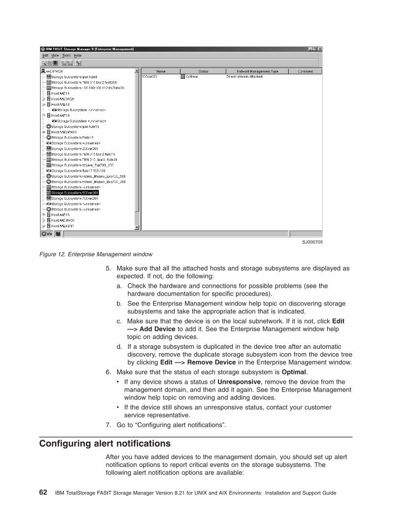
5. Make sure that all the attached hosts and storage subsystems are displayed asexpected. If not, do the following:
a. Check the hardware and connections for possible problems (see thehardware documentation for specific procedures).
b. See the Enterprise Management window help topic on discovering storagesubsystems and take the appropriate action that is indicated.
c. Make sure that the device is on the local subnetwork. If it is not, click Edit—> Add Device to add it. See the Enterprise Management window helptopic on adding devices.
d. If a storage subsystem is duplicated in the device tree after an automaticdiscovery, remove the duplicate storage subsystem icon from the device treeby clicking Edit —> Remove Device in the Enterprise Management window.
6. Make sure that the status of each storage subsystem is Optimal.
v If any device shows a status of Unresponsive, remove the device from themanagement domain, and then add it again. See the Enterprise Managementwindow help topic on removing and adding devices.
v If the device still shows an unresponsive status, contact your customerservice representative.
7. Go to “Configuring alert notifications”.
Configuring alert notificationsAfter you have added devices to the management domain, you should set up alertnotification options to report critical events on the storage subsystems. Thefollowing alert notification options are available:
SJ000705
Figure 12. Enterprise Management window
62 IBM TotalStorage FAStT Storage Manager Version 8.21 for UNIX and AIX Environments: Installation and Support Guide

v Alert notifications are sent to a designated network management station (NMS)using simple network management protocol (SNMP) traps.
v Alert notifications are sent to a designated e-mail address. See the EnterpriseManagement window help for specific procedures. To send e-mail to IBM, contactyour customer service representative.
v Alert notifications are sent to a designated alphanumeric pager when third-partysoftware is used to convert e-mail messages. See the Enterprise Managementwindow help for specific procedures.
For more information about notification options, see IBM FAStT Storage ManagerConcepts Guide, available on your installation CD or at the following Web site:
www.ibm.com/pc/support/
Use the following procedure to set up alert notifications using SNMP traps. Youneed to set up the designated management station only once.
1. Make sure that the installation CD is inserted in the CD-ROM drive on yourdesignated NMS.
2. From the installation CD, copy the SM8_21.MIB file from the SM8mib directoryto the NMS.
3. Follow the steps required by your NMS to compile the MIB. For details, contactyour network administrator or see the documentation for the storagemanagement product you are using.
4. Go to “Starting the Subsystem Management window”.
Starting the Subsystem Management windowIn the Enterprise Management window, select a storage subsystem in one of theseways:
v Click Tools —> Manage Device.
v Right-click the storage subsystem and click Manage Device.
v Double-click the storage subsystem.
The Subsystem Management window for the selected storage subsystem opens(see Figure 13 on page 64).
Note: You can manage one storage subsystem per Subsystem Managementwindow. Open multiple windows to manage other storage subsystems.
Chapter 5. Completing the software installation 63
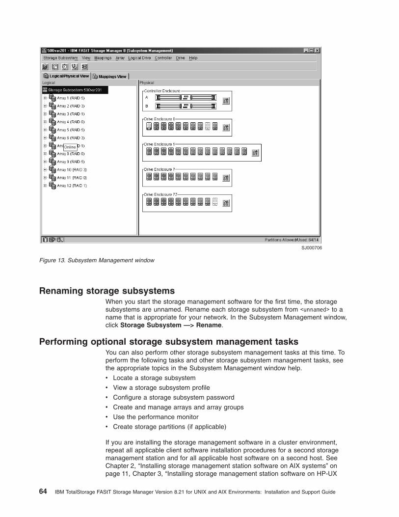
Renaming storage subsystemsWhen you start the storage management software for the first time, the storagesubsystems are unnamed. Rename each storage subsystem from <unnamed> to aname that is appropriate for your network. In the Subsystem Management window,click Storage Subsystem —> Rename.
Performing optional storage subsystem management tasksYou can also perform other storage subsystem management tasks at this time. Toperform the following tasks and other storage subsystem management tasks, seethe appropriate topics in the Subsystem Management window help.
v Locate a storage subsystem
v View a storage subsystem profile
v Configure a storage subsystem password
v Create and manage arrays and array groups
v Use the performance monitor
v Create storage partitions (if applicable)
If you are installing the storage management software in a cluster environment,repeat all applicable client software installation procedures for a second storagemanagement station and for all applicable host software on a second host. SeeChapter 2, “Installing storage management station software on AIX systems” onpage 11, Chapter 3, “Installing storage management station software on HP-UX
SJ000706
Figure 13. Subsystem Management window
64 IBM TotalStorage FAStT Storage Manager Version 8.21 for UNIX and AIX Environments: Installation and Support Guide

systems” on page 35, or Chapter 4, “Installing storage management station softwareon Solaris systems” on page 47 for installation instructions.
Chapter 5. Completing the software installation 65

66 IBM TotalStorage FAStT Storage Manager Version 8.21 for UNIX and AIX Environments: Installation and Support Guide
Chapter 6. Storage Manager 8.21 with high-availability clusterservices
The high-availability clustering services provided by Storage Manager 8.21 allowapplication services to continue when a hardware or software failure occurs. Thissystem protects you from software failures as well as from the failure of a CPU,disk, or LAN component. If a component fails, its redundant partner componenttakes over cluster services and coordinates the transfer between components.
General informationStorage Manager 8.21 is certified for use with the following cluster services:
v MC/Service Guard versions A.11.09 and A.11.13 on HP-UX systems
v Veritas Cluster Server 1.3 and 2.0 on Solaris systems
v Veritas Volume Manager 3.2 on Solaris systems
This document does not describe how to install or configure cluster services. Referto documentation provided with your cluster service products for this information.
Prerequisites for HP-UXYou can choose among many configurations when you set up clustering on anHP-UX system. A minimum configuration consists of two servers that are configuredwith both a primary and two standby LANs to establish a heartbeat LAN.
Provide fibre connections to the storage subsystem through two switches thatprovide the necessary redundant data path for the hosts. Ensure that each serverhas two HP Tachyon host bus adapters.
Prerequisites for Solaris and Veritas Cluster ServerThe following sections contain general hardware requirements and additionalinformation about the cluster services.
General hardware requirementsEach Solaris system in the cluster requires the following hardware:
v At least three Ethernet ports:
– Two for the private network connections
– At least one for the public network connection
v Two fibre host bus adapters for connection to the storage subsystem
v A SCSI connection for operating system disks
v Each Veritas Cluster Server system requires at least 128 MB of RAM and 35 MBof free disk space
System dependenciesThis section provides information about Veritas Volume Manager, RDAC IDs, andsingle points of failure.
© Copyright IBM Corp. 2002 67
Veritas Volume Manager and Data MultipathingIf you are using the Veritas Volume Manager, you must disable Data Multipathing(DMP) either for all devices, or for just FAStT storage servers, depending on yourversion of the Veritas Volume Manager.
For Veritas Volume Manager 3.1 or earlier, follow these steps to disable DMP for alldevices:
1. Open the /etc/system file in the vi text editor by typing the following command:
# vi /etc/system
2. Comment out the forceload: drv/vxdmp line.
3. Save and close the /etc/system file.
For Veritas Volume Manager 3.2 and later, you must disable DMP for FAStT storageservers only. Use option 17 and then option 5 of the submenu of the vxdiskadmutility to do so. Other devices can use DMP.
Note: If you are using the Veritas Cluster Server, you must change the stack sizeparameters. Open the /etc/system file in the vi test editor and make thefollowing updates:
v Change the default value for set lwp_default_stksize to 0x8000
v Change the default value for set rcpcmod:svc_default_stksize to 0x8000
RDAC IDsAdd up to eight additional IDs to the /etc/symsm/rmparams file. Complete thefollowing steps to add them:
1. Open the /etc/symsm/rmparams file in the vi text editor by typing the followingcommand:
# vi /etc/symsm/rmparams
2. Modify the Rdac_HotAddIDs line as follows:
Rdac_HotAddIDs:0:1:2:3:4:5:6:7:8
3. Save and close the /etc/symsm/rmparams file.
Single points of failureWhen setting up cluster services, it is important to eliminate single points of failurebecause a single point of failure makes a cluster only as strong as its weakestcomponent. Set up the storage subsystem for shared storage; for example, all thenodes in the cluster must recognize the same storage and the host types must beset correctly.
Storage Manager 8.21 with General Parallel File System (GPFS)The following section contains general software requirements for Parallel SystemSupport Programs (PSSP) and General Parallel File System (GPFS) support withStorage Manager.
Minimum AIX, PSSP, HACMP, and GPFS software requirementsv PSSP 3.4, APAR IY31786
v GPFS 1.5
68 IBM TotalStorage FAStT Storage Manager Version 8.21 for UNIX and AIX Environments: Installation and Support Guide

FAStT software and firmware requirementsv FAStT Storage Manager v7.10 or v8.21
Configuration limitationsv No direct connection allowed between the host node and a FAStT. Only switched
fabric connection is allowed.
v Each server must have two or four Fibre Channel connections to each attachedFAStT; one connection per FAStT controller host-side minihub; two connectionsper FAStT partition with each connection on different controllers. Theseconnections must be made using two or four Fibre Channel host adapters.Multiple FAStT storage servers can be attached utilizing these same hostadapters (fan out) or by adding additional HBA pairs for each partition.
v A maximum of 4 partitions are allowed per FAStT.
v RVSD Clusters can support a maximum of 2 IBM Virtual Shared Disk and RVSDservers per FAStT partition.
v HACMP/GPFS clusters can support 2 - 32 servers per FAStT partition. In thisenvironment be sure to read and understand the AIX device drivers queue depthsettings as described in Chapter 2, “Installing storage management stationsoftware on AIX systems” on page 11.
v For maximum availability, distribute the HBA and FAStT connections acrossseparate FC switches to minimize the effects of a SAN fabric failure.
v Single Node Quorum is not supported in a dual-node GPFS cluster with FAStTdisks in the configuration.
Other usage notes specific to PSSP/GPFS environmentsIn GPFS file systems the following FAStT cache settings are supported:
v Read cache enabled or disabled
v Write cache enabled or disabled
v Cache mirroring disabled
The performance benefits of read or write caching is application dependent.
GPFS/PSSP logical configuration diagramsThe diagrams that follow show both preferred and fail-over paths from an HBA pairto a given volume or set of volumes. A preferred path to a volume is determinedwhen the volume is created and distributed across a FAStT controller. The controllerto which it is assigned determines which path is “preferred” or active for I/O transfer.Volumes can, and in most cases should, be assigned to both controllers, balancingthe I/O load across HBAs and FAStT controllers.
Chapter 6. Storage Manager 8.21 with high-availability cluster services 69

FC fabric 5
Fabric zone 4
Fabric zone 1
FC fabric 8
FC
SW
FC
SW
RVSD ClusterFAStT500/700
PreferredFail-over
Partition 1
Partition 2
Partition 3
Partition 4
Serverpair
1
Serverpair
4
Port 0
Port 1
Port 0
CTLR A
CTLR B
Port 1
LUN 31LUN 0
LUN 31LUN 1
SJ000886
WWPN-1A
WWPN-7A
WWPN-7AWWPN-8AWWPN-7BWWPN-8B
WWPN-1AWWPN-2AWWPN-1BWWPN-2B
WWPN-2A
WWPN-8A
WWPN-2B
WWPN-8B
WWPN-1B
WWPN-7B
FCFCHA0
FCHA0
FCHA0
FCHA0
FCHA1
FCHA1
FCHA1
FCHA1
FC
VSD 1
FC
FC
VSD 7
FC
FC
VSD 2
FC
FC
VSD 8
Note:The preferred path to a volume is determined by controller assignment of Volume.Volumes can be spread across both controllers (A & B), allowing for static load-balancing.
Figure 14. RVSD Cluster Configuration example with single FAStT500/700 - StorageManager v7.10 or v8.21, shown with 2 partitions (4 maximum) per FAStT
70 IBM TotalStorage FAStT Storage Manager Version 8.21 for UNIX and AIX Environments: Installation and Support Guide

Fabric zone 3
Fabric zone 1
Fabric zone 2
Fabric zone 4
FC
SW
FC
SW
FAStT500/700 #1
FAStT500/700 #2
PreferredFail-over
SJ000887
WWPN-1AWWPN-2AWWPN-1CWWPN-2C
WWPN-2AWWPN-2B
WWPN-1AWWPN-1B
WWPN-2CWWPN-2D
WWPN-1CWWPN-1D
WWPN-1BWWPN-2BWWPN-1DWWPN-2D
WWPN-1AWWPN-2AWWPN-1CWWPN-2C
WWPN-1BWWPN-2BWWPN-1DWWPN-2D
FC
FC
FC
FC
FC
FC
FC
FC
VSD 1
VSD 2
RVSD Cluster
Note:The preferred path to a volume is determined by controller assignment of Volume.
Please note zoning requirements when connecting multiple HBAs to the same FAStT from the same server.Volumes can be spread across both controllers (A & B), allowing for static load-balancing.
Partition 1
Partition 2
Port 1
Port 1
Port 0
Port 0
CTLR A
CTLR B
LUN 31
LUN 31
LUN 0
LUN 0
Partition 1
Partition 2
Port 1
Port 1
Port 0
Port 0
CTLR A
CTLR B
LUN 31
LUN 31
LUN 0
LUN 0
Figure 15. RVSD Cluster Configuration example with multiple FAStT500/700 - StorageManager v7.10 or v8.21, shown with 2 partitions per FAStT
Chapter 6. Storage Manager 8.21 with high-availability cluster services 71

Fabric zone 2
Fabric zone 1
FC
SW
FC
SW
FAStT500/700 #1
FAStT500/700 #2
FAStT500/700 #3
PreferredFail-over
Partition 1
Partition 1
Partition 1
Port 1
Port 1
Port 1
Port 1
Port 1
Port 1
Port 0
Port 0
Port 0
Port 0
Port 0
Port 0
CTLR A
CTLR A
CTLR A
CTLR B
CTLR B
CTLR B
LUN 31
LUN 31
LUN 31
LUN 0
LUN 0
LUN 0
SJ000888
WWPN-1AWWPN-2AWWPN-1BWWPN-2B
WWPN-1A
WWPN-1B
WWPN-2A
WWPN-1B
WWPN-1AWWPN-2AWWPN-1BWWPN-2B
WWPN-1CWWPN-2CWWPN-1DWWPN-2D
FCFCHA0
FCHA0
FCHA1
FCHA1
FC
FC
FC
VSD 1
VSD 2
RVSD Cluster
Note:The preferred path to a volume is determined by controller assignment of Volume.Volumes can be spread across both controllers (A & B), allowing for static load-balancing.
Figure 16. RVSD Cluster Configuration example with multiple FAStT500/700 - StorageManager v7.10 or v8.21, shown with 1 partition per FAStT
72 IBM TotalStorage FAStT Storage Manager Version 8.21 for UNIX and AIX Environments: Installation and Support Guide

Fabric zone 2
Fabric zone 1
FC
SW
FC
SW
FAStT500/700 #1
FAStT500/700 #2
FAStT500/700 #3
FAStT500/700 #4
PreferredFail-over
Partition 1
Partition 1
Partition 1
Partition 1
Port 1
Port 1
Port 1
Port 1
Port 1
Port 1
Port 1
Port 1
Port 0
Port 0
Port 0
Port 0
Port 0
Port 0
Port 0
Port 0
CTLR A
CTLR A
CTLR A
CTLR A
CTLR B
CTLR B
CTLR B
CTLR B
LUN 31
LUN 31
LUN 31
LUN 31
LUN 0
LUN 0
LUN 0
LUN 0
SJ000889
WWPN-1AWWPN-2AWWPN-1BWWPN-2B
WWPN-1AWWPN-2AWWPN-1BWWPN-2B
WWPN-1CWWPN-2CWWPN-1DWWPN-2D
WWPN-1CWWPN-2CWWPN-1DWWPN-2D
FC
FC
FC
FC
FC
FC
FC
FC
VSD 1
VSD 2
RVSD Cluster
Note:The preferred path to a volume is determined by controller assignment of Volume.Volumes can be spread across both controllers (A & B), allowing for static load-balancing.
WWPN-1AWWPN-1B
WWPN-1AWWPN-1B
WWPN-1CWWPN-1D
WWPN-1CWWPN-1D
Figure 17. Typical RVSD Cluster Configuration example with multiple FAStT500/700 - StorageManager v7.10 or v8.21, shown with 1 partition per FAStT
Chapter 6. Storage Manager 8.21 with high-availability cluster services 73

Fabric zone 2
Fabric zone 1
FC
SW
FC
SW
FAStT500/700
HACMP/GPFS ClusterPreferredFailover
Partition 1
Port 1
CTLR A
CTLR B
LUN 31LUN 0
SJ001035
WWPN-1A
WWPN-3A
WWPN-1B
WWPN-3B
WWPN-2A
WWPN-4A
WWPN-32A
WWPN-2B
WWPN-4B
WWPN-32B
Primary:WWPN-1AWWPN-2AWWPN-1BWWPN-2B...WWPN-32A
Failover:WWPN-1AWWPN-2AWWPN-1BWWPN-2B...WWPN-32B
Svr 1
Svr 3
Svr 2
Svr 4
Svr 32
Figure 18. HACMP/GPFS Cluster Configuration example with single FAStT500/700, shownwith one partition per FAStT
74 IBM TotalStorage FAStT Storage Manager Version 8.21 for UNIX and AIX Environments: Installation and Support Guide
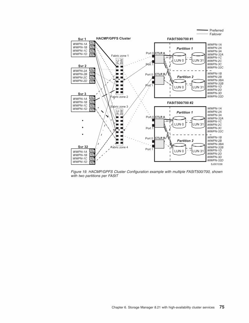
Fabric zone 2
Fabric zone 3
Fabric zone 4
Fabric zone 1
FC
SW
FC
SW
PreferredFailover
SJ001036
Svr 1
Svr 3
Svr 32
Svr 2
FAStT500/700 #1HACMP/GPFS Cluster
FAStT500/700 #2
WWPN-1AWWPN-2AWWPN-3AWWPN-32A
WWPN-1AWWPN-2AWWPN-3AWWPN-32A
WWPN-1BWWPN-2BWWPN-3BAWWPN-32B
WWPN-1BWWPN-2BWWPN-3BAWWPN-32B
WWPN-1CWWPN-2CWWPN-3CWWPN-32C
WWPN-1CWWPN-2CWWPN-3CWWPN-32C
WWPN-1DWWPN-2DWWPN-3DWWPN-32D
WWPN-1DWWPN-2DWWPN-3DWWPN-32D
WWPN-2AWWPN-2B
WWPN-1AWWPN-1B
WWPN-1AWWPN-1B
WWPN-1AWWPN-1B
WWPN-2CWWPN-2D
WWPN-1CWWPN-1D
WWPN-1CWWPN-1D
WWPN-1CWWPN-1D
FC
FC
FC
FC
FC
FC
FC
FC
FC
FC
FC
FC
FC
FC
FC
FC
Partition 1
Partition 1
Partition 2
Partition 2
Port 1
Port 1
Port 1
Port 1
Port 0
Port 0
Port 0
Port 0
CTLR A
CTLR A
CTLR B
CTLR B
LUN 31
LUN 31
LUN 31
LUN 31
LUN 0
LUN 0
LUN 0
LUN 0
Figure 19. HACMP/GPFS Cluster Configuration example with multiple FAStT500/700, shownwith two partitions per FAStT
Chapter 6. Storage Manager 8.21 with high-availability cluster services 75

76 IBM TotalStorage FAStT Storage Manager Version 8.21 for UNIX and AIX Environments: Installation and Support Guide

Chapter 7. FlashCopy and the FAStT Storage Server
This chapter introduces FlashCopy, a premium feature of the FAStT StorageManager 8.21 and describes its various components, what they do, and how to setthem up. This is followed by a step-by-step guide to using several FlashCopyfeatures. Refer to the IBM TotalStorage FAStT700 and Copy Services Redbook forinformation about using automated scripts, the command line interface, examplesand where they can be useful. You will find this redbook at:http://www.ibm.com/redbooks
The FlashCopy option is available for purchase separately from IBM or an IBMBusiness Partner. FlashCopy feature is available only with IBM FAStT StorageManager Version 8.21 and above.
Overview of FlashCopyA FlashCopy logical drive is a point-in-time (PIT) image of a logical drive. It is thelogical equivalent of a complete physical copy, but you create it much more quicklythan a physical copy; it also requires less disk space. In FAStT Storage Manager8.21, the logical drive from which you are basing the FlashCopy, called the baselogical drive, must be a standard logical drive in your storage subsystem.FlashCopy can enable an application, for example a backup application, to accessthe FlashCopy and read the data while its base logical drive remains online anduser-accessible. When the backup completes, the FlashCopy logical drive is nolonger needed.
It is also possible to create several flash copies of a base logical drive and writedata to the FlashCopy logical drives to perform testing and analysis. Beforeupgrading a database management system, for example, you might use FlashCopylogical drives to test different configurations. Then you can use the performancedata that is provided by the storage management software to help you decide howbest to configure your live database system.
When you make a FlashCopy, the controller suspends I/O to the base logical drivefor a few seconds. Meanwhile, it creates a physical logical drive called theFlashCopy repository logical drive to store FlashCopy meta data and copy-on-writedata. When the controller finishes creating the FlashCopy repository logical drive,I/O write requests to the base logical drive can continue. However, before a datablock on the base logical drive is modified, a copy-on-write occurs. This copies thecontents of blocks that are to be modified into the FlashCopy repository logical drivefor safekeeping. Because the FlashCopy repository logical drive stores copies of theoriginal data in those data blocks, further changes to those data blocks write directlyto the base logical drive without another copy-on-write. And, because the only datablocks that are physically stored in the FlashCopy repository logical drive are thosethat have changed since the time of the FlashCopy, the FlashCopy technology usesless disk space than a full physical copy.
When you create a FlashCopy logical drive, you specify where to create theFlashCopy repository logical drive, its capacity, and other parameters. You candisable the FlashCopy when you are finished with it, for example, after a backupcompletes. Then, you can recreate the FlashCopy the next time you do a backupand reuse the same FlashCopy repository logical drive. Using the DisableFlashCopy and Recreate FlashCopy menu options provides a shortcut to create anew FlashCopy logical drive of a particular base logical drive. You do not need to
© Copyright IBM Corp. 2002 77

create a new FlashCopy repository logical drive. You can also delete a FlashCopylogical drive, which also deletes an associated FlashCopy repository logical drive.
The storage management software provides a warning message when a FlashCopyrepository logical drive nears a user-specified threshold (a percentage of its fullcapacity, the default is 50%). When this threshold is met, storage managementsoftware allows you to expand the capacity of a FlashCopy repository logical driveusing free capacity on the array. If no free capacity is available on the array, youcan optionally add unconfigured capacity to the array with which to expand theFlashCopy repository logical drive.
Enabling FlashCopyYou enable the IBM FAStT Storage Manager Version 8.21 FlashCopy feature usingits accompanying Key CD. This CD contains a GenKey program that you must runto enable the FlashCopy feature.
Note: The GenKey program is licensed for use on only one storage subsystem.Purchase a FAStT FlashCopy Premium Feature Key CD for each storagesubsystem on which you want to enable the FAStT FlashCopy feature.
To enable FlashCopy you must perform the following tasks.
1. Obtain the feature enable identifier.
2. Generate the feature key file.
3. Use the feature key file to enable the premium feature.
Obtaining the feature enable identifierEach storage subsystem has its own unique feature enable identifier. This identifierensures that a particular feature key file is applicable only to that storagesubsystem. Complete the following steps to obtain the feature enable identifier.
1. Click Start —> Programs —> FAStT Storage Manager 8.21 Client. TheEnterprise Management window opens.
2. In the left-hand pane, double-click the storage subsystem for which you want toenable the FlashCopy feature. The Subsystem Management window opens forthe selected storage subsystem.
3. In the Subsystem Management window, click Storage Subsystem —>Premium Features —> List. The Premium Feature List window opens anddisplays the feature enable identifier.
4. Record the feature enable identifier.
5. Close the Premium Feature List window.
Generating the feature key fileComplete the following steps to generate the feature key file.
1. Insert the IBM FAStT Storage Manager Version 8.21 FlashCopy PremiumFeature Key CD into the CD-ROM drive.
2. From a command prompt, change to the root directory on the CD-ROM drive;then, type:
GenKey <full pathname and filename><feature enable identifier>
where:
78 IBM TotalStorage FAStT Storage Manager Version 8.21 for UNIX and AIX Environments: Installation and Support Guide

v full pathname is the location at which you want to create the feature key file
v filename is the feature key file name
v feature enable identifier is the feature enable identifier you recorded in“Obtaining the feature enable identifier” on page 78
For example, if you want to create a feature key file named “flashcopy.key” ondrive C, using the feature enable identifier“67890875432145678976543212345678”, type:
GenKey c:\flashcopy.key 67890875432145678976543212345678
Note: Always specify a feature key file name with the .key extension. Thepremium feature user interface uses this extension to filter the files in adirectory.
3. Press Enter. A feature key file is created in the location that you specified instep 2 on page 78.
Using the feature key file to enable FlashCopyComplete the following steps to enable FlashCopy.
1. From the Subsystem Management window, click Storage Subsystem —>Premium Features —> Enable. The Select Feature Key File window opens.
Note: The Select Feature Key File program filters files from the .key extension.
2. Select the folder in which you placed the generated key file.
3. Select the appropriate key file.
4. Click OK.
5. The Enable Feature window opens. Click Yes.
6. The FlashCopy Option is now enabled. The icon in the Premium Feature statusarea no longer displays a red slash. To further verify the status of the option,click Storage Subsystem —> Features —> List
You system is now prepared to schedule use of the FlashCopy feature.
FlashCopy parametersWhen you create a FlashCopy logical drive, you specify where to create theFlashCopy repository logical drive, its capacity, threshold level warning, and otherparameters. The FlashCopy repository logical drive capacity is created as apercentage of the base logical drive and contains the copy-on-write data. TheStorage Management software provides a warning message when your FlashCopyrepository logical drive exceeds the threshold level.
The FlashCopy repository logical drive’s failure policy determines what happenswhen the FlashCopy repository logical drive becomes full (that is, all of its capacityhas been used). The failure policy can be set to either fail the FlashCopy (defaultsetting) or fail incoming I/O to the FlashCopy’s base logical drive.
Do not ignore the FlashCopy repository logical drive ″threshold exceeded″notification. This is the last and only warning you will receive before the FlashCopyrepository logical drive actually becomes full. You have the options either toincrease the capacity of the FlashCopy repository logical drive or increase theFlashCopy repository logical drive threshold capacity warning level. By increasing
Chapter 7. FlashCopy and the FAStT Storage Server 79

the warning threshold, you reduce the amount of time you will have to respond inthe event of a reaching a threshold and receiving a ″threshold exceeded″notification.
If a FlashCopy logical drive or FlashCopy repository logical drive is displayed as amissing logical drive, the storage subsystem has either detected drives associatedwith the FlashCopy, or FlashCopy repository logical drives that are no longeraccessible. Missing logical drives, in most cases, are recoverable. See “Missinglogical drives” on page 120.
FlashCopy logical drivesThe default FlashCopy repository logical drive capacity is initially set to 20% of thebase logical drive, if enough free capacity exists to create a FlashCopy repositorylogical drive of this size. The default threshold level for the FlashCopy repositorylogical drive is initially set to 50%.
If you are not sure how large to make the FlashCopy repository logical drive or howhigh to set the FlashCopy repository logical drive full warning, accept the defaultsettings. You can estimate later how quickly the repository capacity is being used.For more information, see “Estimating FlashCopy repository life” on page 84.
Viewing FlashCopy logical drive failure settingsComplete the following steps to see the current FlashCopy logical drive failuresettings.
1. Select a FlashCopy repository logical drive in the Logical view of the SubsystemManagement window.
2. Click Logical Drive —> Properties, or right-click and select Properties. TheFlashCopy Repository Logical Drive - Properties window opens. See Figure 20on page 81..
80 IBM TotalStorage FAStT Storage Manager Version 8.21 for UNIX and AIX Environments: Installation and Support Guide

3. Click the Capacity tab to view the currently defined settings. See Figure 21 onpage 82.
SJ000825
Figure 20. FlashCopy reposity logical drive properties
Chapter 7. FlashCopy and the FAStT Storage Server 81

If the FlashCopy repository logical drive is set to fail, the data is not recoverablewhen the drive becomes full and FlashCopy cannot be accessed. The onlyavailable option (if this situation occurs) is to delete the FlashCopy logical drive orre-create the FlashCopy logical drive to create a new point-in-time image.
If the FlashCopy repository logical drive is set to fail when writing to the base logicaldrive, the data is recoverable. But, the FlashCopy repository logical drive capacitymust be increased before writes to the base logical drive are not rejected. See“Resizing a FlashCopy repository drive” on page 109.
Note the following points:
v Deleting a FlashCopy logical drive automatically deletes the associatedFlashCopy repository logical drive.
v Deleting a FlashCopy repository logical drive automatically deletes the associatedFlashCopy logical drive.
v Deleting a FlashCopy logical drive and then creating it again forces you to stopthe host application and unmount the base logical drive while the FlashCopy isbeing created again.
v Recreating a FlashCopy logical drive alleviates the need to create a FlashCopyrepository logical drive, as well as remap the assigned logical drive-to-LUNmappings between the FlashCopy logical drive and the host.
v After you recreate the FlashCopy logical drive, you can change parameters onthe FlashCopy repository logical drive through the appropriate menu options.
SJ000826
Figure 21. Repository capacity settings
82 IBM TotalStorage FAStT Storage Manager Version 8.21 for UNIX and AIX Environments: Installation and Support Guide
v To avoid another FlashCopy repository logical drive full failure, increase thecapacity of the FlashCopy repository logical drive. See “Resizing a FlashCopyrepository drive” on page 109.
Estimating FlashCopy repository logical drive capacityWhen a FlashCopy logical drive is created, a physical logical drive called theFlashCopy repository logical drive is also created to store FlashCopy data andcopy-on-write data. The default setting for the FlashCopy repository logical drivecapacity is 20% of the base logical drive’s capacity. In general, this capacity shouldbe sufficient. Use the following information to help determine the appropriatecapacity of the FlashCopy repository logical drive:
v A FlashCopy repository logical drive can be no smaller than 8 MB.
v The amount of write activity to the base logical drive after the FlashCopy logicaldrive has been created dictates the size of a FlashCopy repository logical drive.As the amount of write activity to the base logical drive increases, the number oforiginal data blocks that need to be copied from the base logical drive to theFlashCopy repository logical drive also increases.
v The estimated life expectancy of the FlashCopy logical drive contributes todetermining the capacity of the FlashCopy repository logical drive. The longer aFlashCopy logical drive remains enabled, the FlashCopy repository logical driveruns the increased risk of reaching its maximum capacity. For more information,see “Estimating FlashCopy repository life” on page 84.
v The amount of management overhead required on the FlashCopy repositorylogical drive to store FlashCopy logical drive data contributes to determining thecapacity of the FlashCopy repository logical drive. The amount of managementoverhead actually required is fairly small and can be calculated using the simpleformulas detailed in the following section.
v There is not necessarily a one-to-one correlation between the number of datablocks that change on the base logical drive and the amount of copy-on-writedata that is stored on the FlashCopy repository logical drive. Depending on thelocation of data blocks that need to be copied, for performance reasons, thecontroller might copy over a full set of 32 blocks, even if only one set of blockshas changed. Keep this in mind when determining the percentage of the capacityof the base logical drive that can be copied to the FlashCopy repository logicaldrive.
Calculating expected overheadUse the following formula to calculate the amount of management overhead that isrequired to store FlashCopy data on the FlashCopy repository logical drive. Thisformula should be used merely as a guide, and FlashCopy repository logical drivecapacity should be re-estimated periodically.
Note: Conversion from bytes to kilobytes, and then to megabytes, is required forthis formula.
The formula to calculate the amount of management overhead required is:
192 KB +(X /2000)
Where X is the capacity of the base logical drive in bytes.
ExampleFor a 5 GB base logical drive, where 30% of the data blocks are expected tochange on the base logical drive, the estimated FlashCopy repository logical drivecapacity can be calculated as follows:
Chapter 7. FlashCopy and the FAStT Storage Server 83
1. Convert the capacity of the base logical drive to bytes.
When converted, 5 GB equals 5 368 709 120 bytes.
2. Divide the capacity of the base logical drive (in bytes) by 2000.
When divided, the result is 2,684,354.56 bytes.
3. Convert the result from step 2 (in bytes) to kilobytes (KB).
When converted, the result is 2621.44 KB.
4. Add 192 KB to the results from step 3.
192 KB +2621.44 KB =2813.44 KB
5. Convert the result from step 4 to megabytes (MB).
When converted, the amount of management overhead required is 2.75 MB (or0.002686 GB).
6. In this example, 30% of the data blocks on the base logical drive are expectedto change. To accurately calculate the FlashCopy repository logical drivecapacity, sufficient space needs to be allocated for the copy-on-write data aswell as the management overhead (calculated in step 5).
To calculate the copy-on-write space required, calculate the percentage of thebase logical drive expected change:
30% of 5 GB =1.5 GB
The final estimated FlashCopy repository logical drive capacity for this exampleis:
1.5 GB +0.002686 GB =1.502686 GB
7. In the Create FlashCopy Logical Drive Wizard: Specify Repository Capacitywindow, use the percent (%) full box field to set the estimated FlashCopyrepository logical drive capacity. See Figure 21 on page 82.
Note: The percentage (%) full box sets the FlashCopy repository logical drivecapacity as a percentage of the base logical drive. Using the percent (%)full box field, increase or decrease the percentage until the FlashCopyRepository Logical Drive Capacity value matches the estimated capacitycalculated in step 6. (Some rounding up might be required.)
Estimating FlashCopy repository lifeWhen you create a FlashCopy logical drive, you are asked to define variousproperties for the FlashCopy repository logical drive, including the name of theFlashCopy repository logical drive, its capacity, a logical drive-to-LUN mapping, andthe repository full condition. When defining the properties of the FlashCopyrepository logical drive, keep in mind the kind of usage you have planned for theFlashCopy logical drive. Understanding how the FlashCopy logical drive will beused can help you to estimate the life expectancy of the FlashCopy repositorylogical drive.
If numerous I/O requests are written to the base logical drive, the FlashCopyrepository logical drive (containing the FlashCopy data and copy-on-write data)could eventually exceed the base logical drive capacity if all the original data blocksare changed. The default setting suggests 20% of the base logical drive capacity,but this is a setting that can be adjusted after some usage data becomes available.
The following procedure describes how to estimate the life expectancy of aFlashCopy repository logical drive. Use it merely as a guide. Note that the lifeexpectancy of a FlashCopy repository logical drive should be carefully re-estimatedperiodically.
84 IBM TotalStorage FAStT Storage Manager Version 8.21 for UNIX and AIX Environments: Installation and Support Guide

1. Select the FlashCopy repository logical drive in the Logical view. Click LogicalDrive —> Properties and click the Capacity tab. Alternately, you can right-clickthe FlashCopy repository logical drive, select Properties, and click theCapacity tab.
2. Select the FlashCopy repository logical drive in the Logical view. Click View—>GoTo—> FlashCopy Logical Drive. Alternately, right-click the FlashCopyrepository logical drive and select Go To FlashCopy Logical Drive.
3. Record the creation timestamp day and time.
4. Record the capacity used (GB) and the available capacity (GB).
5. Determine the elapsed time (t) by subtracting the creation time from the currenttime, expressing the elapsed time in either minutes, hours, or days.
6. The total time (Tr) that the repository is available for copy-on-write data can nowbe estimated (based on the current usage) by multiplying the elapsed time (t) bythe available capacity (Ct), and then dividing the resultant number by thecapacity used (Cu).
The formula you need to use is:
Tr =(t *Ct)/Cu
Where:
Tr Total time available
t Elapsed aime
Ct Available aapacity
Cu Capacity used
Note: The total time Available (Tr) indicates the total usage time for theFlashCopy repository logical drive.
Using the result of these calculations, you should now be able to make an informeddecision about whether you should increase the capacity of the FlashCopyrepository logical drive. If the repository capacity becomes 100% full during theexpected lifetime of the FlashCopy, then you should increase capacity of theFlashCopy repository logical drive. For more information, see “Resizing aFlashCopy repository drive” on page 109.
Using FlashCopyThis section presents an easy-to-follow, step-by-step procedural guide to commonadministration tasks for a FAStT FlashCopy solution. The tasks that are coveredinclude:
v Checking the status of the Flash Copy premium feature
v Creating a FlashCopy drive
v Mapping a FlashCopy drive to a host
v Viewing FlashCopy drive status
v Disabling a FlashCopy a drive
v Recreating a FlashCopy drive
v Resizing a FlashCopy repository drive
v Deleting a FlashCopy drive
Chapter 7. FlashCopy and the FAStT Storage Server 85
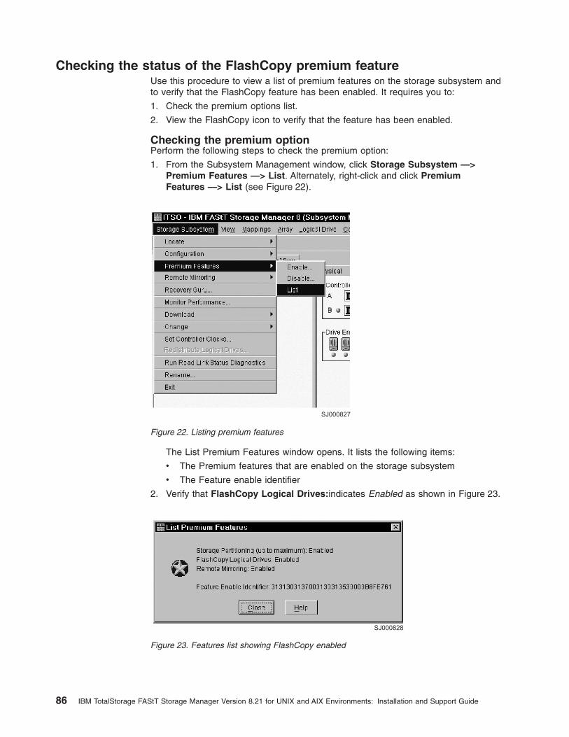
Checking the status of the FlashCopy premium featureUse this procedure to view a list of premium features on the storage subsystem andto verify that the FlashCopy feature has been enabled. It requires you to:
1. Check the premium options list.
2. View the FlashCopy icon to verify that the feature has been enabled.
Checking the premium optionPerform the following steps to check the premium option:
1. From the Subsystem Management window, click Storage Subsystem —>Premium Features —> List. Alternately, right-click and click PremiumFeatures —> List (see Figure 22).
The List Premium Features window opens. It lists the following items:
v The Premium features that are enabled on the storage subsystem
v The Feature enable identifier
2. Verify that FlashCopy Logical Drives:indicates Enabled as shown in Figure 23.
SJ000827
Figure 22. Listing premium features
SJ000828
Figure 23. Features list showing FlashCopy enabled
86 IBM TotalStorage FAStT Storage Manager Version 8.21 for UNIX and AIX Environments: Installation and Support Guide
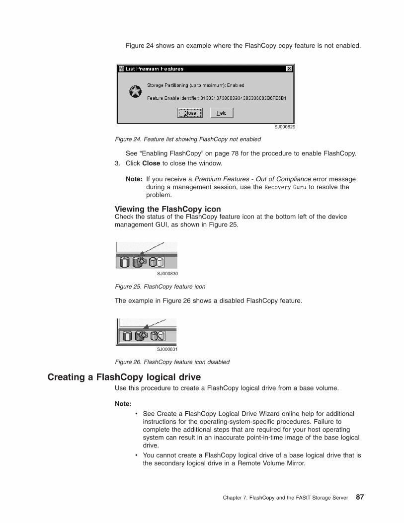
Figure 24 shows an example where the FlashCopy copy feature is not enabled.
See “Enabling FlashCopy” on page 78 for the procedure to enable FlashCopy.
3. Click Close to close the window.
Note: If you receive a Premium Features - Out of Compliance error messageduring a management session, use the Recovery Guru to resolve theproblem.
Viewing the FlashCopy iconCheck the status of the FlashCopy feature icon at the bottom left of the devicemanagement GUI, as shown in Figure 25.
The example in Figure 26 shows a disabled FlashCopy feature.
Creating a FlashCopy logical driveUse this procedure to create a FlashCopy logical drive from a base volume.
Note:
v See Create a FlashCopy Logical Drive Wizard online help for additionalinstructions for the operating-system-specific procedures. Failure tocomplete the additional steps that are required for your host operatingsystem can result in an inaccurate point-in-time image of the base logicaldrive.
v You cannot create a FlashCopy logical drive of a base logical drive that isthe secondary logical drive in a Remote Volume Mirror.
SJ000829
Figure 24. Feature list showing FlashCopy not enabled
SJ000830
Figure 25. FlashCopy feature icon
SJ000831
Figure 26. FlashCopy feature icon disabled
Chapter 7. FlashCopy and the FAStT Storage Server 87

Perform the following steps to create a FlashCopy logical drive:
1. Place the application into backup mode:
a. Stop the host application that is accessing the base logical drive, sync filesystem. Unmount the base logical drive if possible. This enables a validconsistent copy to be taken.
It might not be convenient to stop database applications. However, in thiscase, it is required to place the application into a backup mode or place it inan acquiesced state while you creation the FlashCopy.
b. It is important to back up application recovery files, such as role back andredo logs, because these files might be located in different physical diskstorage or on different logical drives.
2. Launch the Create a FlashCopy Logical Drive Wizard:
a. Select a base logical drive from the Logical view.
b. Click Logical Drive —> FlashCopy —>Create. Alternately, right-click andselect Create FlashCopy Logical Drive. See Figure 27.
The Create a FlashCopy Logical Drive Wizard opens as shown in Figure 28on page 89.
SJ000832
Right-clicking and selectingthe option
Clicking the menu option
Figure 27. Create FlashCopy menu options
88 IBM TotalStorage FAStT Storage Manager Version 8.21 for UNIX and AIX Environments: Installation and Support Guide

Note: If the FlashCopy logical drive is to be based on the root disk of thehost operating system, the final point-in-time image might not becompletely consistent with the base logical drive.
3. Create the FlashCopy logical drive:
a. Review the information in the initial window as shown in Figure 28. Click OKto proceed to the wizard introduction window.
Follow the instructions on each wizard panel, and click the Next buttonwhen you are ready to continue to the next panel.
Note: Each wizard panel has context-sensitive help. Click the Help buttonon a particular panel to receive help for that panel.
b. The Introduction window (Figure 29 on page 90) defines what a FlashCopylogical drive is and the physical components that are associated with aFlashCopy logical drive. It enables you to select either the Simple orAdvanced path through the Create FlashCopy Logical Drive Wizard:
v Simple Path: Proceeds to the Specify Name panel, which provides apreview of the FlashCopy and repository default names. You can alsochange the defaults on this panel.
v Advanced Path: Proceeds to the Allocate Capacity panel. There youselect the Free Capacity or Unconfigured Capacity node on which toplace the FlashCopy repository logical drive.
If no free capacity exists or the available free capacity is unusable, awarning message displays.
SJ000833
Figure 28. Create a FlashCopy Logical Drive Wizard startup
Chapter 7. FlashCopy and the FAStT Storage Server 89

c. If you want to use the Advanced path, select Advanced and click Next. TheAllocate Capacity window (Figure 30 on page 91) opens. From this windowyou can choose free capacity or unconfigured capacity. A description of eachoption follows.
SJ000834
Figure 29. Wizard Introduction window
90 IBM TotalStorage FAStT Storage Manager Version 8.21 for UNIX and AIX Environments: Installation and Support Guide

v Free Capacity:
If you select Free Capacity and click Next, the Specify Logical DriveParameters window (Figure 31 on page 92) opens. Define the FlashCopylogical drive-to-LUN mapping parameter and the FlashCopy repositorylogical drive full conditions. Click Next.
SJ000835
Figure 30. Allocate Capacity window
Chapter 7. FlashCopy and the FAStT Storage Server 91

The Preview window (Figure 32 on page 93) opens and displays theFlashCopy and repository parameters. You can click Back to return to theprevious windows and edit the parameters or click Finish and continue.
SJ000836
Figure 31. Specify Logical Drive Parameters
92 IBM TotalStorage FAStT Storage Manager Version 8.21 for UNIX and AIX Environments: Installation and Support Guide
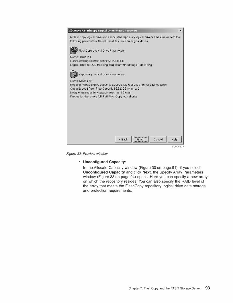
v Unconfigured Capacity:
In the Allocate Capacity window (Figure 30 on page 91), if you selectUnconfigured Capacity and click Next, the Specify Array Parameterswindow (Figure 33 on page 94) opens. Here you can specify a new arrayon which the repository resides. You can also specify the RAID level ofthe array that meets the FlashCopy repository logical drive data storageand protection requirements.
SJ000837
Figure 32. Preview window
Chapter 7. FlashCopy and the FAStT Storage Server 93
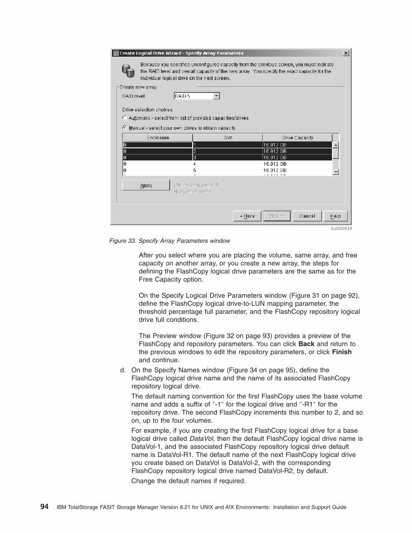
After you select where you are placing the volume, same array, and freecapacity on another array, or you create a new array, the steps fordefining the FlashCopy logical drive parameters are the same as for theFree Capacity option.
On the Specify Logical Drive Parameters window (Figure 31 on page 92),define the FlashCopy logical drive-to-LUN mapping parameter, thethreshold percentage full parameter, and the FlashCopy repository logicaldrive full conditions.
The Preview window (Figure 32 on page 93) provides a preview of theFlashCopy and repository parameters. You can click Back and return tothe previous windows to edit the repository parameters, or click Finishand continue.
d. On the Specify Names window (Figure 34 on page 95), define theFlashCopy logical drive name and the name of its associated FlashCopyrepository logical drive.
The default naming convention for the first FlashCopy uses the base volumename and adds a suffix of ″-1″ for the logical drive and ″-R1″ for therepository drive. The second FlashCopy increments this number to 2, and soon, up to the four volumes.
For example, if you are creating the first FlashCopy logical drive for a baselogical drive called DataVol, then the default FlashCopy logical drive name isDataVol-1, and the associated FlashCopy repository logical drive defaultname is DataVol-R1. The default name of the next FlashCopy logical driveyou create based on DataVol is DataVol-2, with the correspondingFlashCopy repository logical drive named DataVol-R2, by default.
Change the default names if required.
SJ000838
Figure 33. Specify Array Parameters window
94 IBM TotalStorage FAStT Storage Manager Version 8.21 for UNIX and AIX Environments: Installation and Support Guide

Click Next to continue.
Tips about names:
v Regardless of whether you use the software-supplied sequence numberthat (by default) populates the FlashCopy logical drive name orFlashCopy repository logical drive name field, the next default namefor a FlashCopy or FlashCopy repository logical drive still receives asequence number determined by the software. For example, you mightname the first FlashCopy of base logical drive DataVol DataVolMay28,without using the software-supplied sequence number of 1. Regardless,the software assigns a default name for the next FlashCopy as DataVol-2.
v The next available sequence number is based on the number of existingFlashCopies of a base logical drive. If you delete a FlashCopy logicaldrive, its sequence number becomes available again.
v You must choose a unique name for the FlashCopy and FlashCopyrepository logical drives. Otherwise, the system displays an errormessage.
v Names have a 30-character limit. When you reach this limit in either theFlashCopy logical drive name or FlashCopy repository logical drivename field, it no longer accepts input. If the base logical drive namecontains 30 characters, the default names for the FlashCopy and itsassociated FlashCopy repository logical drive use the base logical drivename truncated just enough to add the sequence string. For example, for“Host Software Engineering Group GR-1”, the default FlashCopy namewould be “Host Software Engineering GR-1”. The default repository namewould be “Host Software Engineering G-R1.”
SJ000839
Figure 34. Specify Names window
Chapter 7. FlashCopy and the FAStT Storage Server 95
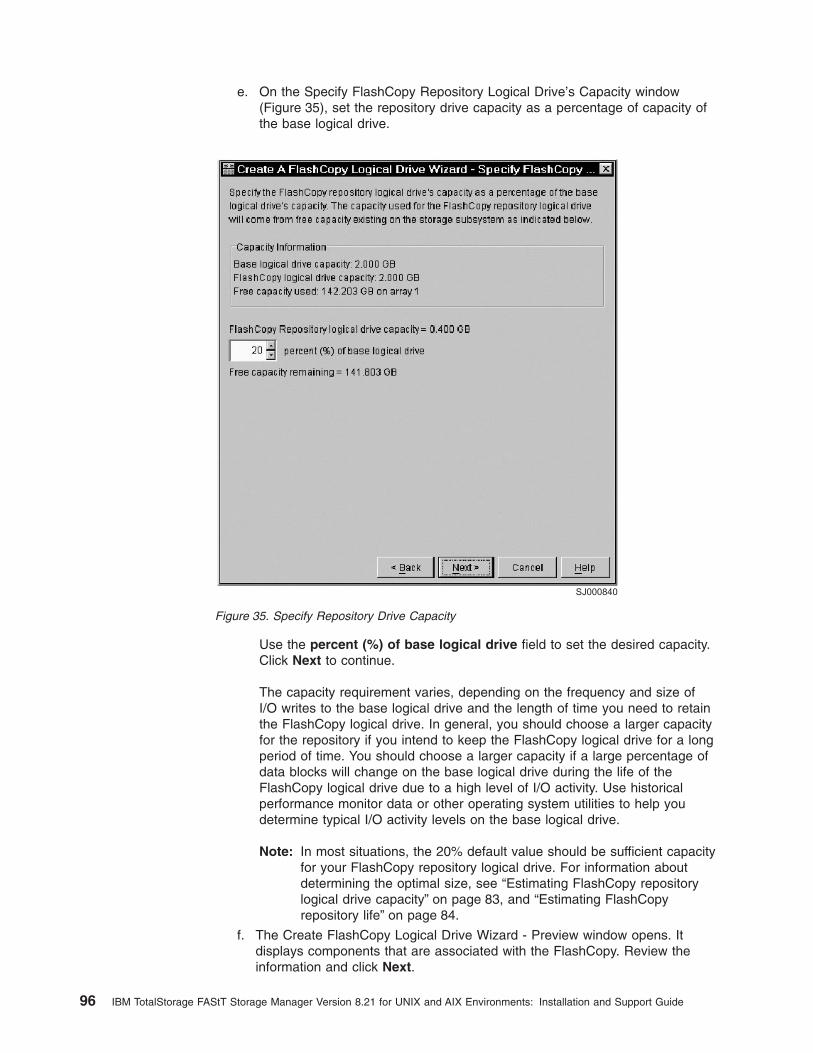
e. On the Specify FlashCopy Repository Logical Drive’s Capacity window(Figure 35), set the repository drive capacity as a percentage of capacity ofthe base logical drive.
Use the percent (%) of base logical drive field to set the desired capacity.Click Next to continue.
The capacity requirement varies, depending on the frequency and size ofI/O writes to the base logical drive and the length of time you need to retainthe FlashCopy logical drive. In general, you should choose a larger capacityfor the repository if you intend to keep the FlashCopy logical drive for a longperiod of time. You should choose a larger capacity if a large percentage ofdata blocks will change on the base logical drive during the life of theFlashCopy logical drive due to a high level of I/O activity. Use historicalperformance monitor data or other operating system utilities to help youdetermine typical I/O activity levels on the base logical drive.
Note: In most situations, the 20% default value should be sufficient capacityfor your FlashCopy repository logical drive. For information aboutdetermining the optimal size, see “Estimating FlashCopy repositorylogical drive capacity” on page 83, and “Estimating FlashCopyrepository life” on page 84.
f. The Create FlashCopy Logical Drive Wizard - Preview window opens. Itdisplays components that are associated with the FlashCopy. Review theinformation and click Next.
SJ000840
Figure 35. Specify Repository Drive Capacity
96 IBM TotalStorage FAStT Storage Manager Version 8.21 for UNIX and AIX Environments: Installation and Support Guide

g. The Create FlashCopy Logical Drive Wizard - Completed window(Figure 36) opens. It display the associated logical drives and componentsthat make up the FlashCopy relationship. Click Finish to continue.
The FlashCopy drives are now displayed in the device management GUI, asshown in Figure 37 on page 98. See “Viewing the FlashCopy icon” onpage 87 for information about interpreting the display icons.
SJ000841
Figure 36. Preview window
Chapter 7. FlashCopy and the FAStT Storage Server 97
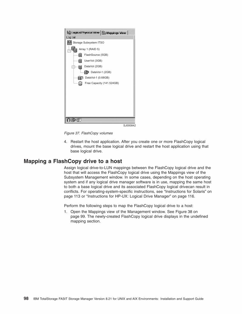
4. Restart the host application. After you create one or more FlashCopy logicaldrives, mount the base logical drive and restart the host application using thatbase logical drive.
Mapping a FlashCopy drive to a hostAssign logical drive-to-LUN mappings between the FlashCopy logical drive and thehost that will access the FlashCopy logical drive using the Mappings view of theSubsystem Management window. In some cases, depending on the host operatingsystem and if any logical drive manager software is in use, mapping the same hostto both a base logical drive and its associated FlashCopy logical drivecan result inconflicts. For operating-system-specific instructions, see “Instructions for Solaris” onpage 113 or “Instructions for HP-UX: Logical Drive Manager” on page 116.
Perform the following steps to map the FlashCopy logical drive to a host:
1. Open the Mappings view of the Management window. See Figure 38 onpage 99. The newly-created FlashCopy logical drive displays in the undefinedmapping section.
SJ000842
Storage Subsystem ITSO
Array 1 (RAID 5)
FlashSource (5GB)
UserVol (3GB)
DataVol (2GB)
DataVol-1 (2GB)
DataVol-1 (0.68GB)
Free Capacity (141.524GB)
Figure 37. FlashCopy volumes
98 IBM TotalStorage FAStT Storage Manager Version 8.21 for UNIX and AIX Environments: Installation and Support Guide

2. Select the host or host group that you want to map the drive.
3. Right-click and select Define Additional Mapping, as shown in Figure 39.
4. The Define Additional Mapping window (Figure 40 on page 100) opens.
a. Select the FlashCopy drive.
b. Select the host or host group.
c. Set the LUN number.
SJ000843
Storage Subsystem ITSO
DataVol-1 =LUN?
Default Group
HostAAE18
HostAAE19
Host ReserchSRV
Host Group ReserchDEPT
Host Ports
Host Ports
Host Ports
Undefined Mappings
Figure 38. Undefined FlashCopy disk
SJ000844
Figure 39. Define Additional Mapping
Chapter 7. FlashCopy and the FAStT Storage Server 99

d. Click Add.
In the example shown in Figure 39 on page 99 and Figure 40, the FlashCopylogical disk DataVol-1 is made available to the backup server host group. Thisenables the backup server to access and mount the disk as part of its own filesystem. It also allows a local backup to be performed by the backup applicationsoftware.
It is possible to map the FlashCopy logical disk to the same server that ownsthe base logical disk. However, immediately after creating the FlashCopy, thetwo logical disks appear exactly the same (a block-by-block copy). Manyoperating systems do not tolerate seeing an exact duplicate volume. You mightneed to complete other steps before you can access it. The mapping is shownin Figure 41 on page 101.
Note: If you use this FlashCopy on a regular basis (for example, for backuppurposes), use the Disable FlashCopy and Re-create FlashCopy optionsto reuse the FlashCopy. Using these options preserves the existingmappings to the FlashCopy logical drive. For more information, see“Disabling a FlashCopy logical drive” on page 106 and “Recreating aFlashCopy logical drive” on page 108.
SJ000845
Figure 40. Define Additional Mapping window
100 IBM TotalStorage FAStT Storage Manager Version 8.21 for UNIX and AIX Environments: Installation and Support Guide

Finally, use specific operating-system and host utilities to mount and use themapped FlashCopy drive.
1. Run the host-based hot_add utility to register the FlashCopy logical drive withthe host operating system.
2. Run the host-based SMdevices utility to associate the mapping between thephysical device name and the logical drive name.
3. Mount the logical drive to the host.
For information about specific host operating-system procedures, see “Instructionsfor Solaris” on page 113 or “Instructions for HP-UX: Logical Drive Manager” onpage 116.
Viewing the FlashCopy logical drive statusYou can determine the status of the FlashCopy logical drive by viewing the iconsthat change depending of the state of the drive. The logical drive componentproperty display is also useful in determining the state of the logical drives.
Use the FlashCopy Repository Logical Drive - Properties window to view theFlashCopy repository logical drive base and capacity properties. You can also usethis window to specify the capacity percentage full and the action to be taken if theFlashCopy repository logical drive becomes full.
The progress of modification operations displays at the bottom of the window.
FlashCopy icon statesTo view the FlashCopy icon, open the Storage Management Device Manager GUIPhysical/Logical view. The icon states are shown in Figure 42 on page 102.
SJ000846
Figure 41. Mapped FlashCopy logical disk
Chapter 7. FlashCopy and the FAStT Storage Server 101

FlashCopy repository propertiesPerform the following steps to view the FlashCopy repository properties:
1. Select a FlashCopy repository logical drive in the Logical view of the SubsystemManagement window.
2. Click Logical Drive —> Properties, or right-click and select Properties, asshown in Figure 43 on page 103.
SJ000847
Figure 42. FlashCopy icon states
102 IBM TotalStorage FAStT Storage Manager Version 8.21 for UNIX and AIX Environments: Installation and Support Guide
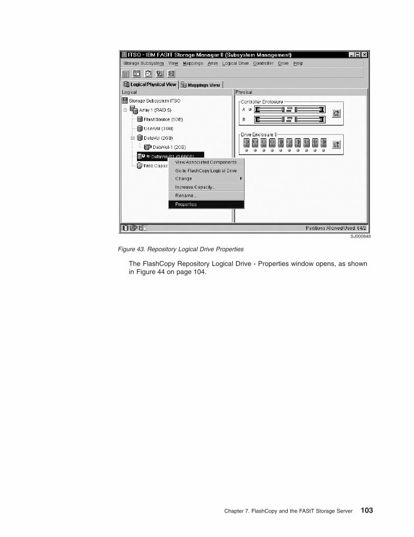
The FlashCopy Repository Logical Drive - Properties window opens, as shownin Figure 44 on page 104.
SJ000848
Figure 43. Repository Logical Drive Properties
Chapter 7. FlashCopy and the FAStT Storage Server 103
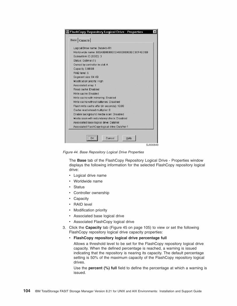
The Base tab of the FlashCopy Repository Logical Drive - Properties windowdisplays the following information for the selected FlashCopy repository logicaldrive:
v Logical drive name
v Worldwide name
v Status
v Controller ownership
v Capacity
v RAID level
v Modification priority
v Associated base logical drive
v Associated FlashCopy logical drive
3. Click the Capacity tab (Figure 45 on page 105) to view or set the followingFlashCopy repository logical drive capacity properties:
v FlashCopy repository logical drive percentage full
Allows a threshold level to be set for the FlashCopy repository logical drivecapacity. When the defined percentage is reached, a warning is issuedindicating that the repository is nearing its capacity. The default percentagesetting is 50% of the maximum capacity of the FlashCopy repository logicaldrives.
Use the percent (%) full field to define the percentage at which a warning isissued.
SJ000849
Figure 44. Base Repository Logical Drive Properties
104 IBM TotalStorage FAStT Storage Manager Version 8.21 for UNIX and AIX Environments: Installation and Support Guide

v Repository full policy
When a FlashCopy repository logical drive reaches its capacity and becomesfull, one of the following actions occurs:
– Fail FlashCopy logical drive
– Fail writes to base logical drive
If the FlashCopy repository logical drive is set to Fail FlashCopy logicaldrive (as shown in Figure 45) when it becomes full, its data is notrecoverable and the FlashCopy cannot be accessed.In this case, the onlyavailable option is to delete the FlashCopy logical drive or recreate theFlashCopy logical drive to create a new point-in-time image.
If the FlashCopy repository logical drive is set to Fail writes to the baselogical drive, the data is recoverable. However, the FlashCopy repositorylogical drive capacity must be increased so writes to the base logical driveare not rejected. For more information, see “Resizing a FlashCopyrepository drive” on page 109.
Viewing the progress of a modification operationThe progress bar at the bottom of the FlashCopy Repository Logical DriveProperties window displays the progress of an operation. You can view the progressof the following operations:
v Copyback
v Reconstruction
v Initialization
v RAID level change
SJ000850
Figure 45. Repository drive warning threshold
Chapter 7. FlashCopy and the FAStT Storage Server 105

v Dynamic logical drive expansion
v Capacity increase
v Defragmentation
v Segment size change
Note: The storage management software cannot obtain progress informationfrom the storage subsystem controllers if the network managementconnection to the controllers is down or if the storage subsystem ispartially managed. For more information about a partially managedstorage subsystem or an unresponsive controller or storage subsystemcondition, see the Enterprise Management window online help.
Disabling a FlashCopy logical driveIf you no longer need a FlashCopy logical drive, you might want to disable it. Aslong as a FlashCopy logical drive is enabled, your storage subsystem performancecan be impacted by copy-on-write activity thst is directed to the associatedFlashCopy repository logical drive. The copy-on-write activity concludes when youdisable a FlashCopy logical drive.
If you disable a FlashCopy logical drive instead of deleting it, you can retain it andits associated repository for future use. When you need to create a differentFlashCopy of the same base logical drive, you can use the Recreate option toreenable the previously disabled FlashCopy. This takes less time than creating anew FlashCopy.
When you disable a FlashCopy logical drive, note the following points:
v You cannot use that FlashCopy logical drive again until you use the Recreateoption on that logical drive.
v Only that FlashCopy logical drive is disabled. All other FlashCopy logical drivesremain functional.
If you do not intend to recreate a FlashCopy, you can delete that FlashCopy logicaldrive instead of disabling it.
Perform the following steps to disable a FlashCopy logical drive:
1. Select the FlashCopy logical drive. Right-click and select Disable, as shown inFigure 46 on page 107.
106 IBM TotalStorage FAStT Storage Manager Version 8.21 for UNIX and AIX Environments: Installation and Support Guide

2. The Disable FlashCopy Logical Drive confirmation window opens. SeeFigure 47. On this window, type Yes and click OK to begin the disable operation.
The FlashCopy icon in the Physical/Logical View now displays as disabled, asshown in Figure 48 on page 108.
SJ000851
Figure 46. Choosing to disable the FlashCopy drive
SJ000852
Figure 47. Disable FlashCopy confirmation window
Chapter 7. FlashCopy and the FAStT Storage Server 107

Recreating a FlashCopy logical driveRecreating a FlashCopy logical drive takes less time than creating a new one. Ifyou have a FlashCopy logical drive that you no longer need, instead of deleting it,you can reuse it (and its associated FlashCopy repository logical drive) to create adifferent FlashCopy logical drive of the same base logical drive.
When you recreate a FlashCopy logical drive, note the following points:
v The FlashCopy logical drive must be in either an optimal or a disabled state.
v All copy-on-write data on the FlashCopy repository logical drive is deleted.
v FlashCopy and FlashCopy repository logical drive parameters remain the sameas the previously disabled FlashCopy logical drive and its associated FlashCopyrepository logical drive. After you recreate a FlashCopy logical drive, you canchange parameters on its associated FlashCopy repository logical drive throughthe appropriate menu options.
v The system retains the original names for the FlashCopy and FlashCopyrepository logical drives. You can change these names, however, after theRecreate option completes.
v When using this option, the previously-configured FlashCopy name, parameters,and FlashCopy repository logical drive are used.
Perform the following steps to recreate a FlashCopy drive:
1. Select the FlashCopy logical drive. Right-click and select Re-Create, as shownin Figure 49 on page 109.
2. The Re-create FlashCopy Logical Drive window opens. Type Yes and click OK.
This command disables and recreates the FlashCopy logical drive (if it had notbeen previously disabled) and displays in the Logical view in an Optimal state. Thecreation timestamp shown on the FlashCopy Logical Drive Properties window isupdated to reflect the new point-in-time image. Copy-on-write activity resumes tothe associated FlashCopy repository logical drive.
SJ000853
Figure 48. Icon showing the disabled FlashCopy logical drive
108 IBM TotalStorage FAStT Storage Manager Version 8.21 for UNIX and AIX Environments: Installation and Support Guide

Note:
v To use the Recreate option, the FlashCopy logical drive must be in eitheran optimal state or a disabled state.
v If the FlashCopy logical drive is in an optimalstate, the process firstdisables and then recreates the FlashCopy logical drive. This processinvalidates the current FlashCopy.
Resizing a FlashCopy repository driveUse this option to increase the storage capacity of an existing FlashCopy repositorylogical drive. Typically, this option is used when a warning is received that theFlashCopy repository logical drive is in danger of becoming full.
You can achieve an increase in storage capacity by:
v Using free capacity available on the array of the FlashCopy repository logicaldrive.
v Adding unconfigured capacity (in the form of unused drives) to the array of theFlashCopy repository logical drive. Use this option when no free capacity existson the array.
Note: A maximum of two drives can be added at one time to increaseFlashCopy repository logical drive capacity.
The storage capacity of a FlashCopy repository logical drive cannot be increased if:
v One or more hot spare drives are in use in the logical drive.
v The logical drive has a non-optimal status.
v Any logical drive in the array is in any state of modification.
v The controller that owns this logical drive is in the process of adding capacity toanother logical drive. Each controller can add capacity to only one logical drive ata time.
v No free capacity exists in the array.
SJ000854
Figure 49. Recreating a FlashCopy
Chapter 7. FlashCopy and the FAStT Storage Server 109

v No unconfigured capacity (in the form of drives) is available to add to the array.
Perform the following steps to resize a FlashCopy repository drive:
1. Select a FlashCopy repository logical drive in the Logical view of the SubsystemManagement window.
2. Click Logical Drive —> Increase Capacity, or right-click and select IncreaseCapacity.
Note: If no free capacity or unconfigured capacity is available, the IncreaseCapacity option is not available.
The Increase Repository Capacity window opens. You can see the FlashCopyrepository logical drive name, the associated FlashCopy logical drive name, theassociated base logical drive name, the current capacity, and the amount of freecapacity that is available for the selected repository.
If free capacity is available, the maximum free space is shown in the IncreaseCapacity by field. If there is no free capacity on the array, the free space that isshown in the Increase Capacity by field is 0. Add drives to create free capacityon the array of the standard logical drive.
3. Use one of the following two methods to increase capacity:
v Increase FlashCopy repository logical drive capacity using free capacity onthe array of the FlashCopy repository logical drive:
a. Accept the final capacity increase or use the Increase Capacity by fieldto adjust the capacity. Click OK.
b. A confirmation window displays. Type Yes and click OK to continue.
The Logical view is updated. The FlashCopy repository logical drive withits capacity increased shows a status of Operation in Progress, togetherwith its original capacity and the total capacity being added.
c. In addition, the Free Capacity node involved shows a reduction incapacity. If all of the free capacity is used to increase the logical drivesize, then the Free Capacity node involved is removed from the Logicalview.
v Increase FlashCopy repository logical drive capacity by adding unconfiguredcapacity (drives) to the array of the FlashCopy repository logical drive:
a. If no unassigned drives are available and empty slots in the driveenclosures are available, insert new drives.
If no unassigned drives are available, and there are no empty slotsavailable in the drive enclosures, install another drive enclosure andadditional drives.
b. Select Add Drives.
The Increase Repository Capacity - Add Free Capacity window opens.Enclosure, slot, and usable capacity details for the available free drivesare displayed.
Note: The drives that are displayed have a capacity that is eitherequivalent to or larger than those that are already employed by thearray.
c. Select a single drive, or two drives, to be added:
– Press Ctrl and click Enter to select the nonadjacent drives.
– Press Shift and click Enter to select the adjacent drives.
d. Click Add.
110 IBM TotalStorage FAStT Storage Manager Version 8.21 for UNIX and AIX Environments: Installation and Support Guide

The Add Free Capacity window closes. Check the Drives to add[enclosure, slot] field to ensure that the correct drives are added.
e. Accept the final capacity or use the Increase Capacity by field to adjustthe capacity.
f. Click OK.
g. A confirmation window opens. Type Yes to confirm the operation, and clickOK to continue.
The Logical view is updated. The FlashCopy repository logical drive havingits capacity increased shows a status of Operation in Progress, togetherwith its original capacity and the total capacity being added. In addition, theFree Capacity node involved in the increase shows a reduction in capacity.
If all of the free capacity is used to increase the logical drives size, then theFree Capacity node involved is removed from the Logical View.
If a Free Capacity node did not exist before you added capacity and not all ofthe capacity that is added will be used to increase the FlashCopy repositorylogical drives capacity, a new Free Capacity node is created and displayed inthe Logical view.
Unassigned drives (unconfigured capacity) that are added to increase theFlashCopy repository logical drives capacity change in the Physical view toassigned drives, and become associated to the array of the FlashCopyrepository logical drive.
4. View the progress of the capacity increase process. Select the FlashCopyrepository logical drive. Click Logical Drive —> Properties, or right-click andselect Properties.
The FlashCopy Repository Logical Drive - Properties window opens. A progressbar at the bottom of the window indicates the status of the capacity increase.
Deleting a FlashCopy driveUse this option to delete a FlashCopy logical drive that is no longer needed forbackup or application testing purposes. This option results in an increase of freecapacity in the array or additional unconfigured capacity.
Note:
v Deleting a logical drive causes loss of all data on the logical drive. Backup the data and stop all I/O before performing this operation, if necessary.
v If a file system is mounted on the logical drive, unmount it before youperforming this operation.
v Deleting a base logical drive automatically deletes the associatedFlashCopy logical drive and FlashCopy repository logical drive.
v Deleting a FlashCopy logical drive automatically deletes the associatedFlashCopy repository logical drive.
v You cannot delete a FlashCopy repository logical drive using the DeleteLogical Drive option, but you can by using the delete command in thescript editor or CLI. See the Enterprise Management window online helpsystem for more information about using the delete command.
Perform the following steps to delete a FlashCopy drive:
1. Select the FlashCopy logical drive in the Logical view.
Chapter 7. FlashCopy and the FAStT Storage Server 111

2. Click Logical Drive —> Delete, or right-click and select Delete, asshown in Figure 50.
3. The Delete FlashCopy Logical Drive window opens, as shown inFigure 51. Type Yes and click OK.
SJ000855
Figure 50. Deleting the FlashCopy logical drive
SJ000856
Figure 51. Delete FlashCopy Logical Drive Dialog window
112 IBM TotalStorage FAStT Storage Manager Version 8.21 for UNIX and AIX Environments: Installation and Support Guide
The FlashCopy logical drive and FlashCopy repository logical drive aredeleted, destroying any data that they might have contained.
Using FlashCopy with UNIX regular disksThis section explains the procedures for using FlashCopy with UNIX regular disks.It outlines the key steps required to create and reuse a FlashCopy logical drive onthe following UNIX-based operating systems, using regular disks:
v Solaris 2.6, 2.7 (Solaris 7), and 2.8 (Solaris 8)
v HP-UX 11.0 (or higher)
Instructions for SolarisUse the following procedures to create and reuse a FlashCopy logical drive usingregular disks on Solaris 2.6, 2.7 (Solaris 7), and 2.8 (Solaris 8). Failure to completethe steps listed may result in an inaccurate point-in-time image of the base logicaldrive.
FlashCopy logical drives can either be created for reuse (frequent or nightlybackups) or for one-time use (speculative change or upgrade testing).
Creating a FlashCopy logical driveBefore you create a FlashCopy logical drive, consider the following questions:
v Are you creating the FlashCopy logical drive for immediate use?
If you plan to use the FlashCopy logical drive immediately,, stop all I/O activity tothe base logical drive. Also, unmount the base logical drives from the host towhich they are currently mounted. This ensures that it will capture an accuratepoint-in-time image of the data on the base logical drive.
v Are you creating the FlashCopy logical drive for use at a later date?
If you plan to use the FlashCopy logical drive at a later date, do not unmount orstop I/O activity to the base logical drive at this time. You must perform theseactivities immediately before you use the FlashCopy logical drive for the firsttime.
Perform the following steps to create a FlashCopy logical drive:
1. Start the Storage Management software. The Enterprise Management windowopens.
2. Within the Logical view of the Subsystem Management window, select astandard logical drive and create a FlashCopy logical drive using one of thefollowing methods:
v Use the Create FlashCopy Logical Drive Wizard. This is accessed using aSubsystem Management window.
v Create a FlashCopy logical drive using either the script editor or acommand-line shell on the host operating system. Type the followingcommand and press Enter.
create FlashCopylogicaldrive
3. Within the Logical view of the Subsystem Management window, select astandard logical drive and create a FlashCopy logical drive using one of thefollowing methods:
v Use the Create FlashCopy Logical Drive Wizard. This is accessed using aSubsystem Management window.
Chapter 7. FlashCopy and the FAStT Storage Server 113

v Create a FlashCopy logical drive using either the script editor or acommand-liine shell on the host operating system. Type the followingcommand and press Enter.
create FlashCopylogicaldrive
4. If supported by the operating system, run the hot_add utility (or operatingsystem-specific utility), or restart the host on which the FlashCopy will be used.This ensures that the host operating system recognizes the FlashCopy logicaldrive.
After you have created logical drives and defined logical drive-to-LUNmappings, run the hot_add utility to ensure that the operating system is awareof the newly-created logical drives, without having to restart the host. Forinformation about which operating systems support the hot_add utility, see theStorage Manager Software Installation Guide for your specific operatingsystem, which is shipped on a CD with the product. You can also download itfrom the Web site at:
http://ssddom02.storage.ibm.com/techsup/webnav.nsf/support/fastt700
For the Solaris operating system, at the host prompt, type the followingcommand and press Enter.
/etc/raid/bin/hot_add
After logical drives are created and logical drive-to-LUN mappings are defined,this step ensures that the operating system is aware of the newly-createdlogical drives, without having to restart the host.
5. Run the SMdevices utility to associate the LUN with a host operating systemdevice and to ensure that the FlashCopy logical drive is recognized by thehost.
After you have created logical drives and defined logical drive-to-LUNmappings, run the SMdevices utility to ensure that the logical drive name andthe operating system device name (assigned by the operating system)correlate.
6. If you plan to use the FlashCopy logical drive immediately, go to step 7. If youplan to use the FlashCopy logical drive at a later date, disable the FlashCopylogical drive now using one of the following methods:
v Click Logical Drive—> FlashCopy —> Disable in the SubsystemManagement window.
v Disable a FlashCopy logical drive using the script editor or a command-lineshell on the host operating system. Type the following command and pressEnter:
disable FlashCopy logical drive
Note: If I/O activity to the base logical drive was stopped or data transferwas suspended, resume I/O activity to the base logical drive orre-enable data transfer at this time.
7. Mount the FlashCopy logical drive to its intended host.
8. Use the FlashCopy logical drive with your backup application, for speculativetesting, or with another application.
9. Unmount the FlashCopy logical drive.
114 IBM TotalStorage FAStT Storage Manager Version 8.21 for UNIX and AIX Environments: Installation and Support Guide

10. After the FlashCopy logical drive is no longer needed, disable or delete theFlashCopy logical drive.
If you disable the FlashCopy logical drive instead of deleting it, you can retainthe FlashCopy logical drive and its associated FlashCopy repository logicaldrive. Then, when you need to create a different FlashCopy of the same baselogical drive, you can recreate the disabled FlashCopy logical drive. This takesless time than creating a new FlashCopy logical drive and avoids anyreduction in performance that migth occur if the FlashCopy logical driveremains available.
Reusing FlashCopy logical drivesTypically, After a FlashCopy logical drive is created, it is disabled until a newpoint-in-time image of the same base logical drive is needed.
Perform the following steps to create a new point-in-time image of the same baselogical drive, complete the following steps:
Note: Stop all I/O activity to the base logical drive at this point (or suspend datatransfer). This ensures that an accurate point-in-time image of the baselogical drive is captured.
1. Unmount the base logical drive.
2. In the Storage Management software, recreate the FlashCopy logical driveusing one of the following methods:
v Click Logical Drive —> FlashCopy —> Re-create from the menus in theSubsystem Management window.
v Recreate a FlashCopy logical drive using the script editor or a command-lineshell on the host operating system. Type the following command and pressEnter.
create FlashCopylogicaldrive
3. Remount the base logical drive to its original host.
4. Mount the FlashCopy logical drive to its intended host.
Note: If you stopped I/O activity to the base logical drive or suspended datatransfer, resume I/O activity to the base logical drive or re-enable datatransfer at this time.
5. Use the FlashCopy logical drive with your backup application or with anotherapplication.
6. Unmount the FlashCopy logical drive.
7. When the FlashCopy logical drive is no longer needed, disable the FlashCopylogical drive.
If you disable the FlashCopy logical drive instead of deleting it, you can retainthe FlashCopy logical drive and its associated FlashCopy repository logicaldrive. Then, when you need to create a different FlashCopy of the same baselogical drive, you can recreate the disabled FlashCopy logical drive. This takesless time than creating a new FlashCopy logical drive and stops any reductionin performance that might occur if the FlashCopy logical drive remains available.
Chapter 7. FlashCopy and the FAStT Storage Server 115

Instructions for HP-UX: Logical Drive ManagerUse the following procedures to create FlashCopy logical drives on a host runningHP-UX 11.0 (or higher) using Logical Volume Manager (LVM). Failure to completethe steps listed can result in an inaccurate point-in-time image of the base logicaldrive.
FlashCopy logical drives can either be created for repeated reuse (frequent ornightly backups) or for one-time use (speculative change or upgrade testing).
Creating a FlashCopy logical drivePerform the following steps to create a FlashCopy logical drive:
1. Start the Storage Management software. The Enterprise Management windowopens.
2. Launch a Subsystem Management window, using one of the followingmethods:
v Select the storage subsystem in the Device Tree view or from the DeviceTable. Then, click the Manage Devicetoolbar button, or click Tools —>Manage Device.
v Right-click the storage subsystem in the Device Tree View or Device Tableand select Manage Device.
v Double-click a storage subsystem node in the Device Table.
v Select the storage subsystem in either the Device Tree view or from theDevice Table and press Enter.
The Subsystem Management window opens in a separate window.
Note: Stop the host application that is accessing the base logical drive andunmount the base logical drive. Unmounting the base logical drive doesnot apply when the base logical drive is the root disk of the hostoperating system.
3. When creating a FlashCopy logical drive based on a mounted file system,always perform a sync to flush the file system cache immediately prior tocreating a FlashCopy logical drive.
At the host prompt, type the following command and press Enter.
sync
All unwritten file system buffers are flushed.
4. Within the Logical view of the Subsystem Management window, select astandard logical drive, and create a FlashCopy logical drive using one of thefollowing methods:
v Use the Create a FlashCopy Logical Drive Wizard. This is accessed usingan Subsystem Management window.
v Create a FlashCopy logical drive using either the script editor or acommand-line shell on the host operating system. Type the followingcommand and press Enter.
create FlashCopylogicaldrive
5. Assign a logical drive-to-LUN mapping between the FlashCopy logical driveand the host that will access the FlashCopy logical drive. Logical drive-to-LUNmappings can be defined using one of the following methods:
116 IBM TotalStorage FAStT Storage Manager Version 8.21 for UNIX and AIX Environments: Installation and Support Guide

v Use the Storage Partitioning Wizard to quickly define a single storagepartition. It guides you through the major steps to specify which host willaccess a logical drive, and the associated LUNs.
v Create a logical drive-to-LUN mapping using the script editor or acommand-line shell on the host operating system. Type the followingcommand and press Enter.
create mapping logical drive
6. At the host prompt, type the following command and press Enter.
ioscan -fn
A list of the mapped devices recognized by the host is displayed.
Note: If the required device names are not displayed using this command, atthe host prompt, type the following command and then press Enter.
insf
7. Remount the base logical drive to its original host.
Note: If I/O activity to the base logical drive was stopped or data transfer wassuspended, resume I/O activity to the base logical drive or reenabledata transfer at this time.
8. Perform the following steps to import the FlashCopy logical drives into theLogical Drive Manager:
a. Create a new directory for the new array, as shown in the followingexample.
mkdir /dev/vg02
b. Create a group node for the new array, as shown in the following example.
mknod /dev/vg02/group c 64 -0x020000
c. Import the FlashCopy logical drive LUNs. At the host prompt, type thefollowing command and press Enter.
vgimport /dev/vg02 FlashCopy-block-node-1 FlashCopy-block-node-2
The following example addresses how to handle reduncancy with multiplepaths. The two paths or nodes represent the primary and alternate paths ofthe FlashCopy volume. Please consider the following example:
vgimport /dev/vg02 /dev/dsk/c66t0d1 /dev/dsk/c69t0d1
Note: You must verify that the /dev/dsk device files exist on the FlashCopylogical drive. Use the SMdevices utility or the HP-UX ioscan utility toperform the verification.
Chapter 7. FlashCopy and the FAStT Storage Server 117

The system displays a warning indicating that a backup of the array beingimported might not exist on the host. This message is only a warning andrequires no response. The import continues and completes successfully.
The backup for this array is created later, when it is exported.
d. Activate the new array as shown in the following example:
vgchange -a y /dev/vg02
9. If a file system existed on the base logical drive, then it also exists on theFlashCopy logical drive. Before you mount the FlashCopy logical drive,however, perform a file system check to ensure that the file system isconsistent, for example:
fsck /dev/vg02/lvol01
10. Mount the FlashCopy logical drive to its intended host.
11. Use the FlashCopy logical drive with your backup application, for speculativetesting, or with another application.
12. Unmount the FlashCopy logical drive.
13. Disable the FlashCopy logical drive using one of the following methods:
v Click Logical Drive —> FlashCopy —> Disable in the SubsystemManagement window.
v Disable a FlashCopy logical drive using the Script Editor or a command lineshell on the host operating system. Type the following command and pressEnter.
disable FlashCopylogicaldrive
Disable the FlashCopy logical drive after it is no longer needed.
If you disable a FlashCopy logical drive instead of deleting it, you can retainthe FlashCopy logical drive and its associated FlashCopy repository logicaldrive. Then, when you need to create a different FlashCopy of the same baselogical drive, you can recreate the disabled FlashCopy logical drive. This takesless time than creating a new FlashCopy logical drive and avoids anyreduction in performance that might result by retaining the availability of anunused FlashCopy logical drive.
Reusing FlashCopy logical drivesTypically, after a FlashCopy logical drive is created it is disabled until a newpoint-in-time image of the same base logical drive is needed. Perform the followingsteps to create a new point-in-time image of the same base logical drive:
Note: Stop all I/O activity to the base logical drive (or suspend data transfer). Thisensures that an accurate point-in-time image of the base logical drive iscaptured.
To create a FlashCopy logical drive, complete the following steps:
1. Start the Storage Management software. The Enterprise Management windowopens.
2. Launch a Subsystem Management window using one of the following methods:
118 IBM TotalStorage FAStT Storage Manager Version 8.21 for UNIX and AIX Environments: Installation and Support Guide

v Select the storage subsystem in either the Device Tree View or DeviceTable. Then, click the Manage Device toolbar button or click Tools—>Manage Device.
v Right-click the storage subsystem in the Device Tree View or Device Table,and select Manage Device.
v Double-click a storage subsystem node in the Device Table.
v Select the storage subsystem in the Device Tree View or the Device Table,and then press Enter.
The Subsystem Management window opens in a separate window.
3. Unmount the base logical drive.
4. In the Storage Management software, recreate the FlashCopy logical driveusing one of the following methods:
v Click Logical Drive —> FlashCopy —> Re-create in the SubsystemManagement window.
v Recreate a FlashCopy logical drive using the script editor or acommand-line shell on the host operating system. Type the followingcommand and press Enter.
recreateFlashCopy logical drive
5. Remount the base logical drive to its original host.
Note: If you stopped I/O activity to the base logical drive or suspended a datatransfer, resume I/O activity to the base logical drive or re-enable datatransfer at this time.
6. Perform the following steps to import the FlashCopy logical drives into theLogical Drive Manager:
a. Create a new directory for the new array as shown in the followingexample.
mkdir /dev/vg02
b. Create a group node for the new array as shown in the following example.
mknod /dev/vg02/group c 64 -0x020000
c. Import the FlashCopy logical drive LUNs. At the host prompt, type thefollowing command and press Enter.
vgimport /dev/vg02 FlashCopy-block-node-1 FlashCopy-block-node-2 ...
An alternate command can be used as shown in the following example.
vgimport /dev/vg02 /dev/dsk/c66t0d1 /dev/dsk/c69t0d1
Note: You must verify that the /dev/dsk device files must exist on theFlashCopy logical drive. Use the SMdevices utility or the HP-UXioscan utility to perform this verification.
Chapter 7. FlashCopy and the FAStT Storage Server 119

A warning is displayed indicating that a backup of the array being importedmight not exist on the host. This message is only a warning and can beignored. The import continues and completes successfully.
The backup for this array is created when it is exported later.
d. Activate the new array, as shown in the following example.
vgchange -a y /dev/vg02
7. If a file system existed on the base logical drive, then it also exists on theFlashCopy logical drive. However, before the FlashCopy logical drive can bemounted, submit it to a file system check.
Perform a file system check to ensure that the file system is consistent, forexample:
fsck /dev/vg02/lvol01
8. Mount the FlashCopy logical drive to its intended host.
9. Use the FlashCopy logical drive with your backup application or otherapplication.
10. Unmount the FlashCopy logical drive.
11. If the FlashCopy logical drive is no longer needed, disable the FlashCopylogical drive.
If you disable the FlashCopy logical drive instead of deleting it, you can retainthe FlashCopy logical drive and its associated FlashCopy repository logicaldrive. Then, when you need to create a different FlashCopy of the same baselogical drive, you can recreate the disabled FlashCopy logical drive. This takesless time than creating a new FlashCopy logical drive and stops any reductionin performance that might occur if the FlashCopy logical drive remainsavailable.
Script editor and command-line interfaceMany storage management options that are available through the SubsystemManagement window can be sent to the storage subsystem using statements inscripts. You can use the script editor to create or edit a script file, save a script fileto the local disk of the Storage Management station, or load a script file from disk.You can also use the command-line interface (CLI) to issue individual commands tothe scripting engine from the host operating system command shell or to callcomplete prewritten scripts.
See the IBM TotalStorage FAStT700 and Copy Services Redbook, SG24–6808 forinformation about using the script editor, examples of automated scripts, andinformation about the command-line interface (CLI). You will find this redbook at:
www.ibm.com/redbooks
Missing logical drivesA missing logical drive is a placeholder node that is displayed in the Logical view. Itindicates that the storage subsystem has detected inaccessible drives that areassociated with a logical drive. Typically, this results when drives that areassociated with an array are removed, or when one or more drive enclosures losepower.
120 IBM TotalStorage FAStT Storage Manager Version 8.21 for UNIX and AIX Environments: Installation and Support Guide

Missing logical drives are only displayed in the Logical view if they are standardlogical drives or repository logical drives. In addition, one of the following conditionsmust exist:
v The logical drive has an existing logical drive-to-LUN mapping, and drives thatare associated with the logical drive are no longer accessible.
v The logical drive is participating in a Remote Volume Mirror as either a primarylogical drive or secondary logical drive, and drives that are associated with thelogical drive are no longer accessible.
v The logical drive is a mirror repository logical drive, and drives that areassociated with the logical drive are no longer accessible. The Recovery Guruhas a special recovery procedure for this case. Two mirror repository logicaldrives are created together on the same array when the Remote VolumeMirroring premium feature is activated and one is used for each controller in thestorage subsystem. If drives that are associated with the array are no longeraccessible, then both mirror repository logical drives are missing, and all RemoteVolume Mirrors are in an Unsynchronized state.
v The logical drive is a base logical drive with associated FlashCopy logical drives,and drives that are associated with the logical drive are no longer accessible.
v The logical drive is a FlashCopy repository logical drive, and drives that areassociated with the logical drive are no longer accessible.
If missing logical drives are detected by the storage subsystem, a Missing LogicalDrives group is created in the Logical view of the Subsystem Management window.Each missing logical drive is shown and identified by its worldwide name and logicaldrive type. Missing logical drives are identified as being either a standard logicaldrive, base logical drive, FlashCopy repository logical drive, primary logical drive,secondary logical drive, or mirror repository logical drive.
Missing logical drives, in most cases, are recoverable. Do not delete missing logicaldrives without confirming that the logical drives are no longer needed, because theywill be permanently removed from the configuration.
If the storage subsystem detects that logical drives are missing because they haveeither been accidentally removed or their drive enclosures have sustained a powerloss, you can recover these logical drives by using either of the following methods:
v Reinsert the drives back into the drive enclosure.
v Ensure that the power supplies of the drive enclosure are properly connected toan operating power source and have an optimal status.
Chapter 7. FlashCopy and the FAStT Storage Server 121

122 IBM TotalStorage FAStT Storage Manager Version 8.21 for UNIX and AIX Environments: Installation and Support Guide

Appendix A. AIX system requirements
This appendix lists the minimum hardware and software requirements that an AIXsystem must meet to be used in a FAStT200, FAStT500, or FASTtT700 storagesubsystem that is managed by Storage Manager 8.21. A README Text filecontaining the latest installation and user information about the storagemanagement software, AIX filesets, and hardware components are located in theAIX subdirectory on the FAStT Installation CD. The most recent copy, whichsupercedes this document, is maintained on the following Web site:
http://www.pc.ibm.com/qtechinfo/MIGR-43793.html
Once there, follow the link to v8.21 information.
Hardware requirementsThe following hardware is required at a minimum.
v Any RS/6000® or eServer pSeries™ server that supports FC 6227 or FC 6228host bus adapters
v Two host bus adapters (HBAs)
Software requirementsThe following software must be at the specified versions.
v AIX 4.3.3 or AIX 5.1
v Filesets associated with IBM RDAC driver installations listed in Table 10 orTable 11
RDAC installation requirementsThe following filesets must be at the specified versions or later.
v For AIX 4.3.3:
Table 10. Filesets required for AIX 4.3.3 RDAC
PTF filesets Version
devices.fcp.disk.array.diag 4.3.3.50
devices.fcp.disk.array.rte 4.3.3.83
devices.common.IBM.fc.rte 4.3.3.75
devices.pci.df1000f7.com 4.3.3.83
devices.pci.df1000f7.rte 4.3.3.75
devices.pci.df1000f9.rte 4.3.3.75
devices.scsi.scarray.rte 4.3.3.50
v For AIX 5.1:
Table 11. Filesets required for AIX 5.1 RDAC
PTF filesets Version
devices.fcp.disk.array.diag 5.1.0.25
devices.fcp.disk.array.rte 5.1.0.37
© Copyright IBM Corp. 2002 123

Table 11. Filesets required for AIX 5.1 RDAC (continued)
PTF filesets Version
devices.common.IBM.fc.rte 5.1.0.10
devices.pci.df1000f7.com 5.1.0.28
devices.pci.df1000f7.rte 5.1.0.15
devices.pci.df1000f9.rte 5.1.0.15
devices.scsi.scarray.rte 5.1.0.0
Note: The AIX RDAC driver files are not included on the FAStT installation CD.Either install them from the AIX Operating Systems CD, if the correct versionis included, or download them directly from the Web site as follows::
techsupport.services.ibm.com/server/fixes
For downloading instructions, see “Installing host RDAC software on AIXhosts” on page 14.
124 IBM TotalStorage FAStT Storage Manager Version 8.21 for UNIX and AIX Environments: Installation and Support Guide
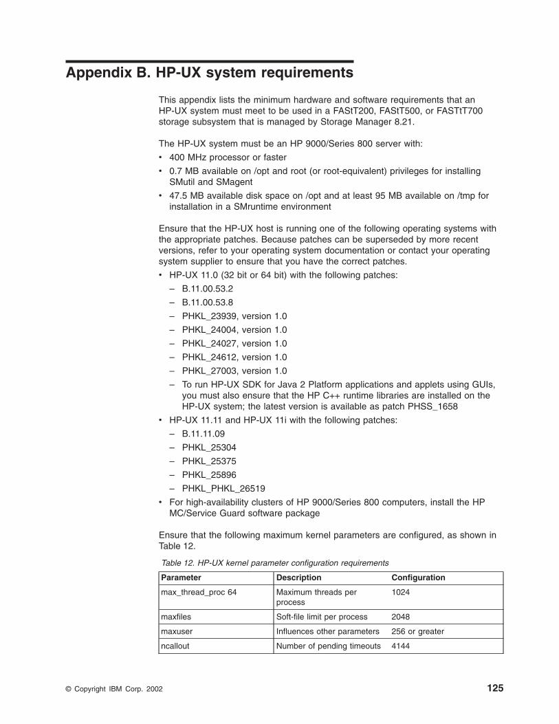
Appendix B. HP-UX system requirements
This appendix lists the minimum hardware and software requirements that anHP-UX system must meet to be used in a FAStT200, FAStT500, or FASTtT700storage subsystem that is managed by Storage Manager 8.21.
The HP-UX system must be an HP 9000/Series 800 server with:
v 400 MHz processor or faster
v 0.7 MB available on /opt and root (or root-equivalent) privileges for installingSMutil and SMagent
v 47.5 MB available disk space on /opt and at least 95 MB available on /tmp forinstallation in a SMruntime environment
Ensure that the HP-UX host is running one of the following operating systems withthe appropriate patches. Because patches can be superseded by more recentversions, refer to your operating system documentation or contact your operatingsystem supplier to ensure that you have the correct patches.
v HP-UX 11.0 (32 bit or 64 bit) with the following patches:
– B.11.00.53.2
– B.11.00.53.8
– PHKL_23939, version 1.0
– PHKL_24004, version 1.0
– PHKL_24027, version 1.0
– PHKL_24612, version 1.0
– PHKL_27003, version 1.0
– To run HP-UX SDK for Java 2 Platform applications and applets using GUIs,you must also ensure that the HP C++ runtime libraries are installed on theHP-UX system; the latest version is available as patch PHSS_1658
v HP-UX 11.11 and HP-UX 11i with the following patches:
– B.11.11.09
– PHKL_25304
– PHKL_25375
– PHKL_25896
– PHKL_PHKL_26519
v For high-availability clusters of HP 9000/Series 800 computers, install the HPMC/Service Guard software package
Ensure that the following maximum kernel parameters are configured, as shown inTable 12.
Table 12. HP-UX kernel parameter configuration requirements
Parameter Description Configuration
max_thread_proc 64 Maximum threads perprocess
1024
maxfiles Soft-file limit per process 2048
maxuser Influences other parameters 256 or greater
ncallout Number of pending timeouts 4144
© Copyright IBM Corp. 2002 125

126 IBM TotalStorage FAStT Storage Manager Version 8.21 for UNIX and AIX Environments: Installation and Support Guide
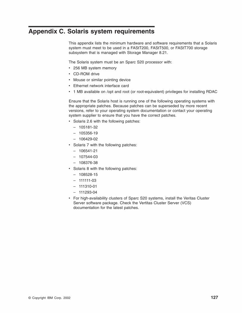
Appendix C. Solaris system requirements
This appendix lists the minimum hardware and software requirements that a Solarissystem must meet to be used in a FAStT200, FAStT500, or FAStT700 storagesubsystem that is managed with Storage Manager 8.21.
The Solaris system must be an Sparc S20 processor with:
v 256 MB system memory
v CD-ROM drive
v Mouse or similar pointing device
v Ethernet network interface card
v 1 MB available on /opt and root (or root-equivalent) privileges for installing RDAC
Ensure that the Solaris host is running one of the following operating systems withthe appropriate patches. Because patches can be superseded by more recentversions, refer to your operating system documentation or contact your operatingsystem supplier to ensure that you have the correct patches.
v Solaris 2.6 with the following patches:
– 105181-32
– 105356-19
– 106429-02
v Solaris 7 with the following patches:
– 106541-21
– 107544-03
– 108376-38
v Solaris 8 with the following patches:
– 108528-15
– 111111-03
– 111310-01
– 111293-04
v For high-availability clusters of Sparc S20 systems, install the Veritas ClusterServer software package. Check the Vertitas Cluster Server (VCS)documentation for the latest patches.
© Copyright IBM Corp. 2002 127

128 IBM TotalStorage FAStT Storage Manager Version 8.21 for UNIX and AIX Environments: Installation and Support Guide

Appendix D. MC Service Guard configuration details
Note: The Hewlett Packard publication Managing MC/ServiceGuard suggests usingvgimport -m -s with LVM commands during the configuration distributionprocess. It is important to consider, however, that the vgimport commanddoes not preserve the primary and alternate paths of the imported volumegroups.
When vgimport reconstructs the newly imported volume groups, entries are madein the /etc/lvmtab file. In this process of reconstruction, the system reorders disks inthe file. The revised order of LUNs on the list causes LUNs to remain onnon-preferred paths after failover. You might expect this condition to occur duringdistribution of the volume groups using the following LVM command:
vgimport -s -m /tmp/<vg_group_name>.map /dev/<vg_group_name>
This precaution applies only when you use the -s option to import devices or diskswith redundant paths. The condition occurs because the -s option causes a searchon the system for each disk when used with vgimport.
When the new list is prepared, the links that were previously designated as primaryand alternate might not remain as they had been configured on node A.
Use the following procedure to correct the paths that were changed in this waywhen using vgimport -m -s with LVM commands.
Note: The following instructions are for a two-node cluster. You can easily expandor adapt these instructions to accommodate a cluster which has more thantwo nodes.
1. Identify and note the primary and alternate paths for each device by typing thefollowing command:
# SMdevices
2. Compare the primary and alternate paths for each device on node A to Node Bby using the vgdisplay -v command. As previously noted, an expected behaviorof the vgimport -m -s command is that the primary and alternate paths changduring export.
On node A:
#vgdisplay -v <volume_group_name>
On node B:
#vgdisplay -v <volume_group_name>
3. If the original primary path of a disk becomes an alternate path after the newlyimported volume group entry is created in /etc/lvmtab, the order can be easilyreverted by using vgreduce to remove the wrong primary path and then usingvgextend to add the path back again:
© Copyright IBM Corp. 2002 129

#vgreducevg1 /dev/dsk/<device_name>#vgextend vg1/dev/dsk/<device_name
130 IBM TotalStorage FAStT Storage Manager Version 8.21 for UNIX and AIX Environments: Installation and Support Guide

Appendix E. JNI Host Bus Adapter settings
The following table detail settings for the various host bus adapter (HBA) cards forSun Solaris. These cards are not plug-and-play with auto-configuration. Instead,they may require manual alteration of the settings/bindings.
Table 13. Configuration file name: /kernel/drv/fca-pci.conf
Original value New value Comments
fca_nport = 0; fca_nport = 1;
ip_disable = 0; ip_disable =1;
failover = 0; failover = 30;
busy_retry_delay=5000;
busy_retry_delay = 5000;
link_recovery_delay =1000;
link_recovery_delay = 1000;
scsi_probe_delay =5000;
scsi_probe_delay = 5000;
def_hba_binding =“fca-pci*”;
def_hba_binding = “nonjni”;
def_wwnn_binding =“$xxxxxx”
def_wwnn_binding = “xxxxxx” Uncomment the line.
def_wwpn_binding =“$xxxxxx”
same Uncomment the line.
Will be added byreconfigure script
name=“fca-pci” parent=“<physical path>”unit-address=“<#>”
Uncomment the line.
Will be added byreconfigure script
target0_hba=“fca-pci0”target0_wwpn=“<controller wwpn>”;
Will be added byreconfigure script
name=“fca-pci” parent=“<physicalpath>”unit-address=“<#>”
Will be added byreconfigure script
target0_hba=“fca-pci1” target0_wwpn=“<controller wwpn>”;
Note: You might need to run the /etc/raid/bin/genjniconf reconfigure script from theSolaris shell.
# /etc/raid/bin/genjniconf
Table 14. Configuration file name: /kernel/drv/jnic146x.conf
Original value New value Comments
FcLoopEnabled = 1 FcLoopEnabled = 0 Uncomment the line.
FcFabricEnabled = 0 FcFabricEnabled = 1 Uncomment the line.
FailoverDelay = 30; FailoverDelay = 30; Uncomment the line.
JniCreationDelay = 5; JniCreationDelay = 10; Uncomment the line.
def_wwnn_binding =“$xxxxxxxxxxx”
def_wwnn_binding = “xxxxxxxxxxx” Uncomment the line.
def_wwpn_binding =“$xxxxxxxxxxx”
same as the original entry Uncomment the line.
© Copyright IBM Corp. 2002 131

Table 14. Configuration file name: /kernel/drv/jnic146x.conf (continued)
Original value New value Comments
Add target0_hba = “jnic146x0”;
Add target0_wwpn = “<controller wwpn>”
Add target1_hba = “jnic146x1”;
Add target1_wwpn = “<controller wwpn>”
Note: You might need to run the /etc/raid/bin/genjniconf reconfigure script from theSolaris shell.
# /etc/raid/bin/genjniconf
Table 15. Configuration file name: /kernel/drv/jnic.conf
Original value New value Comment
FcLoopEnabled = 1 FcLoopEnabled = 0 Uncomment the line.
FcFabricEnabled = 0 FcFabricEnabled = 1 Uncomment the line.
FailoverDelay = 30; FailoverDelay = 30; Uncomment the line.
JniCreationDelay = 5; JniCreationDelay = 10; Uncomment the line.
def_wwnn_binding =“$xxxxxxxxxxx”
def_wwnn_binding = “xxxxxxxxxxx” Uncomment the line.
def_wwpn_binding =“$xxxxxxxxxxx”
same as the original entry Uncomment the line.
Add target0_hba = “jnic146x0”;
Add target0_wwpn = “<controller wwpn>”
Add target1_hba = “jnic146x1”;
Add target1_wwpn = “<controller wwpn>”
Note:
v You might need to run the /etc/raid/bin/genjniconf reconfigure script fromthe Solaris shell.
# /etc/raid/bin/genjniconf
v Set portEnabled = 1; only when you see JNI cards enteringnon-participating mode in the /var/adm/messages file. Under thatcondition:
1. Set FcPortCfgEnabled = 1;
2. Restart the host.
3. Set FcPortCfgEnabled = 0;
4. Restart the host again.
When you have done so, check /var/adm/messages to be sure that itsets the JNI cards to Fabric or Loop mode.
Table 16. Configuration file name: /kernel/drv/fcaw.conf
Original value New value Comments
fca_nport = 0; fca_nport =1;
132 IBM TotalStorage FAStT Storage Manager Version 8.21 for UNIX and AIX Environments: Installation and Support Guide

Table 16. Configuration file name: /kernel/drv/fcaw.conf (continued)
Original value New value Comments
ip_disable = 0; ip_disable=1;
failover = 0; failover =30;
busy_retry_delay =5000;
busy_retry_delay = 5000;
link_recovery_delay =1000;
link_recovery_delay = 1000;
scsi_probe_delay =5000;
scsi_probe_delay = 5000;
def_hba_binding =“fcaw*”;
Uncomment the line.
def_wwnn_binding =“$xxxxxx”
def_wwnn_bindindef_hba_ binding =“nonjni”; g = “xxxxxx”
Uncomment the line.
def_wwnn_binding =“$xxxxxx”
Same as the original entry. Uncomment the line.
Will be added byreconfigure script
name=“fcaw” parent=“<physicalpath>”unit-address=“<#>”
Will be added byreconfigure script
target0_hba=“fcaw0”target0_wwpn=“<controller wwpn>”;
Will be added byreconfigure script
name=“fcaw” parent=“<physicalpath>”unit-address=“<#>”
Will be added byreconfigure script
target0_hba=“fcaw0” target0_wwpn=“<controller wwpn>”;
Note: You might need to run the /etc/raid/bin/genscsiconf reconfigure script fromthe shell prompt.
# /etc/raid/bin/genscsiconf
Appendix E. JNI Host Bus Adapter settings 133

134 IBM TotalStorage FAStT Storage Manager Version 8.21 for UNIX and AIX Environments: Installation and Support Guide

Notices
This publication was developed for products and services offered in the U.S.A.
IBM may not offer the products, services, or features discussed in this document inother countries. Consult your local IBM representative for information on theproducts and services currently available in your area. Any reference to an IBMproduct, program, or service is not intended to state or imply that only that IBMproduct, program, or service may be used. Any functionally equivalent product,program, or service that does not infringe any IBM intellectual property right may beused instead. However, it is the user’s responsibility to evaluate and verify theoperation of any non-IBM product, program, or service.
IBM may have patents or pending patent applications covering subject matterdescribed in this document. The furnishing of this document does not give you anylicense to these patents. You can send license inquiries, in writing, to:
IBM Director of LicensingIBM CorporationNorth Castle DriveArmonk, NY 10504-1785U.S.A.
The following paragraph does not apply to the United Kingdom or any othercountry where such provisions are inconsistent with local law:INTERNATIONAL BUSINESS MACHINES CORPORATION PROVIDES THISPUBLICATIONS ″AS IS″ WITHOUT WARRANTY OF ANY KIND, EITHEREXPRESS OR IMPLIED, INCLUDING, BUT NOT LIMITED TO, THE IMPLIEDWARRANTIES OF NON-INFRINGEMENT, MERCHANTABILITY OR FITNESS FORA PARTICULAR PURPOSE. Some states do not allow disclaimer of express orimplied warranties in certain transactions, therefore, this statement may not apply toyou.
This information could include technical inaccuracies or typographical errors.Changes are periodically made to the information herein; these changes will beincorporated in new editions of the publications. IBM may make improvements orchanges (or both) in the product(s) or program(s) (or both), described in thispublication at any time without notice.
IBM may use or distribute any of the information you supply in any way it believesappropriate without incurring any obligation to you.
Some software may differ from its retail version (if available), and may not includeuser manuals or all program functionality.
TrademarksThe following terms are trademarks of International Business Machines Corporationin the United States, other countries, or both:
IBMAIXe(logo)
© Copyright IBM Corp. 2002 135

NetfinityRS/6000TotalStorage
Microsoft Windows and Windows NT are registered trademarks of MicrosoftCorporation in the United States, other countries, or both.
Java and all Java-based trademarks and logos are trademarks or registeredtrademarks of Sun Microsystems, Inc. in the United States, other countries, or both.
UNIX is a registered trademark of The Open Group in the United States and othercountries.
Other company, product, or service names may be trademarks or service marks ofothers.
IBM agreement for licensed internal codeYou accept the terms of this Agreement1 by your initial use of a machine thatcontains IBM Licensed Internal Code (called “Code”). These terms apply to Codeused by certain Machines IBM or your reseller specifies (called “SpecificMachines”). International Business Machines Corporation or one of its subsidiaries(“IBM”) owns copyrights in Code or has the right to license Code. IBM or a thirdparty owns all copies of Code, including all copies made from them.
If you are the rightful possessor of a Specific Machine, IBM grants you a license touse the Code (or any replacement IBM provides) on, or in conjunction with, only theSpecific Machine for which the Code is provided. IBM licenses the Code to only onerightful possessor at a time.
Under each license, IBM authorizes you to do only the following:
1. execute the Code to enable the Specific Machine to function according to itsOfficial Published Specifications (called “Specifications”);
2. make a backup or archival copy of the Code (unless IBM makes one availablefor your use), provided you reproduce the copyright notice and any other legendof ownership on the copy. You may use the copy only to replace the original,when necessary; and
3. execute and display the Code as necessary to maintain the Specific Machine.
You agree to acquire any replacement for, or additional copy of, Code directly fromIBM in accordance with IBM’s standard policies and practices. You also agree touse that Code under these terms.
You may transfer possession of the Code to another party only with the transfer ofthe Specific Machine. If you do so, you must 1) destroy all your copies of the Codethat were not provided by IBM, 2) either give the other party all your IBM-providedcopies of the Code or destroy them, and 3) notify the other party of these terms.IBM licenses the other party when it accepts these terms. These terms apply to allCode you acquire from any source.
Your license terminates when you no longer rightfully possess the Specific Machine.
1. Form Z125-4144
136 IBM TotalStorage FAStT Storage Manager Version 8.21 for UNIX and AIX Environments: Installation and Support Guide

Actions you must not takeYou agree to use the Code only as authorized above. You must not do, forexample, any of the following:
1. Otherwise copy, display, transfer, adapt, modify, or distribute the Code(electronically or otherwise), except as IBM may authorize in the SpecificMachine’s Specifications or in writing to you;
2. Reverse assemble, reverse compile, or otherwise translate the Code unlessexpressly permitted by applicable law without the possibility of contractualwaiver;
3. Sublicense or assign the license for the Code; or
4. Lease the Code or any copy of it.
Notices 137

138 IBM TotalStorage FAStT Storage Manager Version 8.21 for UNIX and AIX Environments: Installation and Support Guide
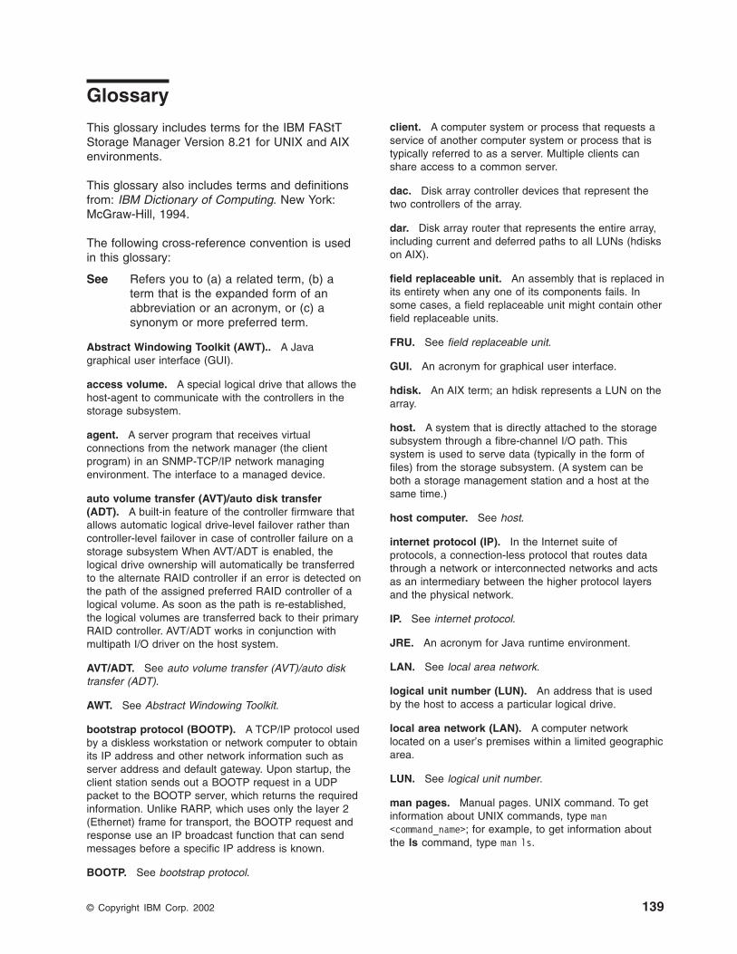
Glossary
This glossary includes terms for the IBM FAStTStorage Manager Version 8.21 for UNIX and AIXenvironments.
This glossary also includes terms and definitionsfrom: IBM Dictionary of Computing. New York:McGraw-Hill, 1994.
The following cross-reference convention is usedin this glossary:
See Refers you to (a) a related term, (b) aterm that is the expanded form of anabbreviation or an acronym, or (c) asynonym or more preferred term.
Abstract Windowing Toolkit (AWT).. A Javagraphical user interface (GUI).
access volume. A special logical drive that allows thehost-agent to communicate with the controllers in thestorage subsystem.
agent. A server program that receives virtualconnections from the network manager (the clientprogram) in an SNMP-TCP/IP network managingenvironment. The interface to a managed device.
auto volume transfer (AVT)/auto disk transfer(ADT). A built-in feature of the controller firmware thatallows automatic logical drive-level failover rather thancontroller-level failover in case of controller failure on astorage subsystem When AVT/ADT is enabled, thelogical drive ownership will automatically be transferredto the alternate RAID controller if an error is detected onthe path of the assigned preferred RAID controller of alogical volume. As soon as the path is re-established,the logical volumes are transferred back to their primaryRAID controller. AVT/ADT works in conjunction withmultipath I/O driver on the host system.
AVT/ADT. See auto volume transfer (AVT)/auto disktransfer (ADT).
AWT. See Abstract Windowing Toolkit.
bootstrap protocol (BOOTP). A TCP/IP protocol usedby a diskless workstation or network computer to obtainits IP address and other network information such asserver address and default gateway. Upon startup, theclient station sends out a BOOTP request in a UDPpacket to the BOOTP server, which returns the requiredinformation. Unlike RARP, which uses only the layer 2(Ethernet) frame for transport, the BOOTP request andresponse use an IP broadcast function that can sendmessages before a specific IP address is known.
BOOTP. See bootstrap protocol.
client. A computer system or process that requests aservice of another computer system or process that istypically referred to as a server. Multiple clients canshare access to a common server.
dac. Disk array controller devices that represent thetwo controllers of the array.
dar. Disk array router that represents the entire array,including current and deferred paths to all LUNs (hdiskson AIX).
field replaceable unit. An assembly that is replaced inits entirety when any one of its components fails. Insome cases, a field replaceable unit might contain otherfield replaceable units.
FRU. See field replaceable unit.
GUI. An acronym for graphical user interface.
hdisk. An AIX term; an hdisk represents a LUN on thearray.
host. A system that is directly attached to the storagesubsystem through a fibre-channel I/O path. Thissystem is used to serve data (typically in the form offiles) from the storage subsystem. (A system can beboth a storage management station and a host at thesame time.)
host computer. See host.
internet protocol (IP). In the Internet suite ofprotocols, a connection-less protocol that routes datathrough a network or interconnected networks and actsas an intermediary between the higher protocol layersand the physical network.
IP. See internet protocol.
JRE. An acronym for Java runtime environment.
LAN. See local area network.
logical unit number (LUN). An address that is usedby the host to access a particular logical drive.
local area network (LAN). A computer networklocated on a user’s premises within a limited geographicarea.
LUN. See logical unit number.
man pages. Manual pages. UNIX command. To getinformation about UNIX commands, type man<command_name>; for example, to get information aboutthe ls command, type man ls.
© Copyright IBM Corp. 2002 139

management information base (MIB). Theinformation that is on an agent. It is an abstraction ofconfiguration and status information.
MIB. See management information base.
NMS. An acronym for network management station.
NVSRAM. An acronym for nonvolatile storage randomaccess memory.
ODM. An acronym for Object Data Manager.
PDF. An acronym for portable document format.
program temporary fix (PTF). A temporary solution orbypass of a problem diagnosed by IBM in a currentunaltered release of a program.
PTF. See program temporary fix.
RDAC. See redundant dual active controller.
redundant dual active controller (RDAC). Alsoknown as redundant disk array controller, provides amultipath driver for a storage subsystem. Used with AIXand Solaris hosts.
router. A computer algorithm that determines the pathof least resistance for traffic on a computer network.
SAM. System Administrator Manager.
SAN. See storage area network.
storage area network (SAN). Dedicated, high-speednetworks of directly connected storage elementsdesigned to move large amounts of data betweenhost-independent distributed storage devices.
storage management station. A system that is usedto manage the storage subsystem. This system doesnot need to be attached to the storage subsystemthrough the fibre-channel I/O path.
server. A functional hardware and software unit thatdelivers shared resources to workstation client units ona computer network.
simple network management protocol (SNMP). ATCP/IP protocol that generally uses the user datagramprotocol (UDP) to exchange messages between amanagement information base and a management clientresiding on a network. Because SNMP does not rely onthe underlying communication protocols, it can be madeavailable over other protocols, such as UDP/IP. In theInternet suite of protocols, a network managementprotocol that is used to monitor routers and attachednetworks. SNMP is an application layer protocol.Information on devices that are managed is defined andstored in the application’s management informationbase (MIB).
SNMP. See simple network management protocol andSNMPv1.
SNMPv1. The original standard for SNMP is nowreferred to as SNMPv1.
subnet. A part of a network that is identified by aportion of an IP address.
TCP. A communication protocol used in the Internetand in any network that follows the Internet EngineeringTask Force (IETF) standards for internetwork protocol.TCP provides a reliable host-to-host protocol betweenhosts in packed-switched communication networks andin interconnected systems of such networks. It uses theInternet Protocol (IP) as the underlying protocol.
TCP/IP. See transmission control protocol/internetprotocol.
transmission control protocol/internet protocol(TCP/IP). A set of communication protocols thatsupport peer-to-peer connectivity functions for both localand wide-area networks.
trap. A mechanism for SNMP agents to notify theSNMP management station of significant events.
worldwide name (WWN). A unique identifier for aswitch on local and global networks.
WWN. See worldwide name.
140 IBM TotalStorage FAStT Storage Manager Version 8.21 for UNIX and AIX Environments: Installation and Support Guide

Index
Aabout this document xiaccess volumes 3, 7actions you must not take 137address
for e-mail comments xivfor reader comment form xivof IBM xivof the IBM director of licensing 135
agent softwareinstalling 38, 52package 5
agreement for licensed internal code 136AIX
configuration 15, 17direct-attached configuration 3, 12firmware
requirements 11upgrading 16verifying 14
hardware requirements 11, 123host software
installing 13, 14prerequisites 15
identifyingcontroller ID numbers 25device names and bus numbers 26logical drives by operating system device
names 29NVSRAM requirements 11operating system requirements 9prerequisites 14RDAC driver
configuring 17installing 15, 17requirements 3, 14, 123
requirementshardware 11, 123host software 14operating system 9RDAC driver 3, 14, 123software 123system 123
restrictions 3, 5, 6, 7, 13SMruntime installing 13software requirements 123system requirements 123volumes, redistributing in case of failure 32
alert notifications, configuring 62attributes
dac 20, 23dar 18, 22definitions 18hdisk 20, 23, 24LUN 20, 23, 24RDAC driver 17
audience of this document xi
AVT/ADT, description 2
Bbooks xii, 1bus numbers and device names, identifying 26, 44
Cchanging the host type 59client software
HP-UXinstalling 38requirements 36
package 3, 4Solaris
installing 49requirements 49uninstalling 55
cluster servicesconfigurations 60description 3hardware requirements 67HP-UX requirements 67MC/Service Guard 67Solaris requirements 67, 68system dependencies 67Veritas Cluster Server 67Veritas Volume Manager 67, 68
command line interface 2commands
fget_config 28lsattr 28lsdev 27
comments about this document, how to send xivconfiguration details, MC Service Guard 129configuration replication 2configuring
AIX 17alert notifications 62direct-attached 3, 12RDAC driver 17, 68Solaris with JNI host bus adapter cards 56storage subsystems
AIX 3, 12, 15HP-UX 39procedures 60Solaris 54
controllersdiagnostics 2firmware 1, 14, 40, 54ID numbers, identifying 25, 44IP addresses 9properties 44volumes 2
creating a direct-attached configuration 12
© Copyright IBM Corp. 2002 141

Ddac attributes 20, 23dar attributes 18, 22default partitioning, Solaris devices 55devices
identification 25names and bus numbers, identifying 26, 44Solaris, default partitioning for 55
diagnostics, controller 2direct (out-of-band) management method 7direct-attached configuration 3, 12documentation
books xiidocuments 1files 1online help xiii, 1, 62, 64related publications xiiWeb sites xii, xiii, 1
drives, AIX, identifying by operating system devicenames 29
Ee-mail address xiv, 63edition notice iienabling multipath I/O with PV-links 41Enterprise Management window
description 4online help 1starting 60
event monitoring 2
Ffailover protection 3failure support
cluster services 3, 67RDAC driver 3, 5redistributing volumes 32
FAStT, introduction to 9features of Storage Manager 8.21 2fget_config command 28filesets 123firmware
AIXrequirements 11upgrading 16verifying 14
description 1HP-UX
requirements 35upgrading 40
Solarisrequirements 47upgrading 54
versions 40, 54FlashCopy 3, 77
command line interface 120create drive 87delete drive 111
FlashCopy (continued)disabling logical drive 106estimate repository life 84estimate repository logical drive capacity 83HP-UX instructions 116mapping drive to host 98missing logical drives 120paremeters 79premium features 86progress of modification operation 105re-create logical drive 108re-size repository drive 109script editor 120script scenarios 77step-by-step guide 85UNIX regular disks 113view status 101
GGPFS 68
HHACMP 68hardware requirements
AIX 11, 123HP-UX 35, 125Solaris 47, 127
hdiskattributes 20
hdisk attributes 20, 23, 24help xiii, 1, 62, 64heterogeneous environment 2, 60high-availability cluster services 3, 67, 68host software
AIX 14AIX installing 13packages 3Solaris 50, 51
host type 57, 59host-agent (in-band) management method 6how this document is organized xihow to send your comments xivHP-UX
client softwareinstalling 38procedure 36, 37requirements 36
cluster services, requirements 67configuration of storage subsystem 39firmware
requirements 35upgrading 40
hardware requirements 35, 125identifying
controller ID numbers 44device names and bus numbers 44
NVSRAMrequirements 35upgrading 40
142 IBM TotalStorage FAStT Storage Manager Version 8.21 for UNIX and AIX Environments: Installation and Support Guide

HP-UX (continued)operating system requirements 9requirements
client software 36cluster services 67firmware 35hardware 35, 125NVSRAM 35operating system 9software 125system 125
software requirements 125system requirements 125
HyperTerminal version 9
IIBM
address xivagreement for licensed internal code 136director of licensing address 135e-mail address xiv, 63
identifyingAIX
controller ID numbers 25device names and bus numbers 26logical drives by operating system device
names 29HP-UX
controller ID numbers 44device names and bus numbers 44
in-band (host-agent) management method 6installing
AIXhost software 13, 14RDAC driver 15SMruntime 13
host software 13, 36, 50HP-UX
client software 38host software 36
post-installation tasks 59sequence of 3SMruntime 13Solaris
client software 49host software 50RDAC driver 51utility software 52
IP addresses for FAStT controllers 9
JJNI
cards 56settings 131
Llicensed internal code, agreement 136
logical drivesAIX, identifying by operating system device
names 29lsattr command 28lsdev command 27LUN attributes 23LUNs
and access volumes 7attributes 20, 23, 24
Mmanagement method
direct (out-of-band) 7host-agent (in-band) 6
management station 1See storage management station
Mappings window 45MC Service Guard 129MC/Service Guard 67missing logical drives 120multipath I/O with PV-links 41
Nnotices
edition iigeneral 135
NVSRAMAIX requirements 11HP-UX
requirements 35upgrading 40
Solarisrequirements 47upgrading 54
Oonline help xiii, 1, 62, 64operating system
AIX 9, 123HP-UX 9, 125requirements
AIX 11HP-UX 35Solaris 47
Solaris 9, 127organization of this document xiout-of-band (direct) management method 7overview of heterogeneous hosts 60
Ppartitioning for Solaris devices 55performing optional storage subsystem management
tasks 64prerequisites
AIXfirmware 11
Index 143

prerequisites (continued)AIX (continued)
hardware 11, 123host software 14operating system 9RDAC driver 3, 14, 123software 123system 123
cluster services 67HP-UX
client software 36cluster services 67firmware 35hardware 35, 125NVSRAM 35operating system 9software 125system 125
Solarisclient software 49cluster services 67, 68firmware 47hardware 47, 127host software 51NVSRAM 47operating system 9RDAC driver 3, 51software 127system 127utility software 51
products, developed 135prohibited actions 137PSSP 68PV-links 41
RRDAC driver
AIXconfiguring 17installing 15, 17requirements 3, 14, 123
attributes 17description 3, 5IDs 68Solaris
installing 51requirements 3, 51uninstalling 55
reader comment form xivREADME.txt file 1redistributing volumes in case of failure 32redundant dual active controller (RDAC) 3related publications xiirenaming storage subsystem 64requirements
AIXfirmware 11hardware 11, 123host software 14operating system 9
requirements (continued)AIX (continued)
RDAC driver 3, 14, 123software 123system 123
cluster services 67HP-UX
client software 36cluster services 67firmware 35hardware 35, 125NVSRAM 35operating system 9software 125system 125
Solarisclient software 49cluster services 67, 68firmware 47hardware 47, 127host software 51NVSRAM 47operating system 9RDAC driver 3, 51software 127system 127utility software 51
resourcesdocuments xii, 1e-mail address xiv, 63files 1online help xiii, 1, 62, 64Web sites xii, xiii, 1
restrictionsAIX 3, 5, 6, 7, 13
Ssending your comments to IBM xivservices offered in the U.S.A. 135setting
host type on Solaris 57IP addresses 9NMS for SNMP notification 63
SMagentagent software
See agent softwareSMclient
client softwareSee client software
SMruntimeAIX installing 13HP-UX installing 36Solaris installing 48
SMutilutility software
See utility softwareSNMP notification 63software package
RDAC 5smagent 4
144 IBM TotalStorage FAStT Storage Manager Version 8.21 for UNIX and AIX Environments: Installation and Support Guide

software package (continued)SMagent 5SMutil 5
software requirementsAIX 123HP-UX 125Solaris 127
Solarisclient software
installing 49procedure 49requirements 49uninstalling 55
cluster services requirements 67, 68configuration of storage subsystem 54devices, default partitioning 55firmware
requirements 47upgrading 54
hardware requirements 47, 127host software
installing 50procedure 51requirements 51
JNI host bus adapter cards 56NVSRAM
requirements 47upgrading 54
operating system requirements 9RDAC driver
installing 51requirements 3, 51uninstalling 55
requirementsclient software 49cluster services 67firmware 47hardware 47, 127host software 51NVSRAM 47operating system 9RDAC driver 3, 51software 127system 127utility software 51
setting the host type 57software requirements 127system requirements 127utility software
installing 52requirements 51uninstalling 55
starting the Enterprise Management window 60starting the Subsystem Management window 63storage management station 1Storage Manager software
features 2installation sequence 3introduction 1software packages 3uninstalling, Solaris 55
storage subsystemcluster services 67configuration replication 2configuring
AIX 15HP-UX 39procedures 60Solaris 54
event monitoring 2introduction 1logical drives
identifying by operating system device names 29management methods
direct (out-of-band) 7host-agent (in-band) 6
management tasks 64renaming 64
Subsystem Management windowdescription 5figure of 63online help 1starting 63
system requirementsAIX 123HP-UX 125Solaris 127
Ttrademarks 135
Uuninstalling Storage Manager software, Solaris 55upgrading
AIX firmware 16HP-UX
firmware 40NVSRAM 40
Solarisfirmware 54NVSRAM 54
utility softwarepackage 5Solaris
installing 52requirements 51uninstalling 55
Vvariable settings for JNI adapter cards 56verifying AIX host firmware 14Veritas Cluster Server 67Veritas Volume Manager 67, 68volumes
redistributing in case of failure 32
Index 145

WWeb sites xii, xiii, 1who should
read this document xiuse this document xi
146 IBM TotalStorage FAStT Storage Manager Version 8.21 for UNIX and AIX Environments: Installation and Support Guide

Readers’ Comments — We’d Like to Hear from You
IBM TotalStorage FAStT Storage Manager Version 8.21 forUNIX and AIX EnvironmentsInstallation and Support Guide
Publication No. GC26-7490-01
Overall, how satisfied are you with the information in this book?
Very Satisfied Satisfied Neutral Dissatisfied Very DissatisfiedOverall satisfaction h h h h h
How satisfied are you that the information in this book is:
Very Satisfied Satisfied Neutral Dissatisfied Very DissatisfiedAccurate h h h h h
Complete h h h h h
Easy to find h h h h h
Easy to understand h h h h h
Well organized h h h h h
Applicable to your tasks h h h h h
Please tell us how we can improve this book:
Thank you for your responses. May we contact you? h Yes h No
When you send comments to IBM, you grant IBM a nonexclusive right to use or distribute your comments in anyway it believes appropriate without incurring any obligation to you.
Name Address
Company or Organization
Phone No.

Readers’ Comments — We’d Like to Hear from YouGC26-7490-01
GC26-7490-01
����Cut or FoldAlong Line
Cut or FoldAlong Line
Fold and Tape Please do not staple Fold and Tape
Fold and Tape Please do not staple Fold and Tape
NO POSTAGENECESSARYIF MAILED IN THEUNITED STATES
BUSINESS REPLY MAILFIRST-CLASS MAIL PERMIT NO. 40 ARMONK, NEW YORK
POSTAGE WILL BE PAID BY ADDRESSEE
International Business Machines CorporationRCF Processing DepartmentDept. M86/Bldg. 050-35600 Cottle RoadSan Jose, CA 95193-0001
_ _ _ _ _ _ _ _ _ _ _ _ _ _ _ _ _ _ _ _ _ _ _ _ _ _ _ _ _ _ _ _ _ _ _ _ _ _ _ _ _ _ _ _ _ _ _ _ _ _ _ _ _ _ _ _ _ _ _ _ _ _ _ _ _ _ _ _ _ _ _ _ _ _ _ _ _ _ _ _ _ _ _ _ _ _ _ _ _
_ _ _ _ _ _ _ _ _ _ _ _ _ _ _ _ _ _ _ _ _ _ _ _ _ _ _ _ _ _ _ _ _ _ _ _ _ _ _ _ _ _ _ _ _ _ _ _ _ _ _ _ _ _ _ _ _ _ _ _ _ _ _ _ _ _ _ _ _ _ _ _ _ _ _ _ _ _ _ _ _ _ _ _ _ _ _ _ _
__
__
__
__
__
__
__
__
__
__
__
__
__
__
__
__
__
__
__
__
__
__
__
__
__
__
__
__
__
__
__
__
__
__
__
__
__
__
__
__
__
__
__
__
__
__
__
__
__
_


����
Printed in U.S.A.
GC26-7490-01

Spin
ein
form
atio
n:
��
�
IBM
Tota
lSto
rage
FASt
TSt
orag
eM
anag
erVe
rsio
n8.
21fo
rU
NIX
and
AIX
Env
iron
men
tsIn
stal
latio
nan
dSu
ppor
tGui
de