installation and testing practices - liberated … · navair 01-1a-505-4 t.o. 1-1a-14-4 tm...
TRANSCRIPT
NAVAIR 01-1A-505-4T.O. 1-1A-14-4TM 1-1500-323-24-413 AUGUST 2004
TECHNICAL MANUAL
INSTALLATION AND TESTING PRACTICES
AIRCRAFTFIBER OPTIC
CABLING
DISTRIBUTION STATEMENT A. Approved for public release; distribution is unlimited.
DESTRUCTION NOTICE - For unclassified, limited documents, destroy by any methodthat will prevent disclosure of contents or reconstruction of the document.
PUBLISHED BY DIRECTION OF COMMANDER, NAVAL AIR SYSTEMS COMMAND
NATEC ELECTRONIC MANUAL
0801LP1035786

NUMERICAL INDEX OF EFFECTIVE WORK PACKAGES/PAGES
Original ........................ 0 ................... 13 August 2004
Only those work packages/pages assigned to the manual are listed in this index. Insert Change, dated .Dispose of superseded and deleted work packages/pages. Superseded and deleted classified work packages/pages shall be destroyed in accordance with applicable regulations. If changed pages are issued to a work package,insert the changed pages in the applicable work package. The portion of text affected in a changed or revised workpackage is indicated by change bars or the change symbol "R" in the outer margin of each column of text. Changesto illustrations are indicated by pointing hands or change bars as applicable. Changes to wiring diagrams andschematics are indicated by shading.
Change ....................... 0 ......................... 15 Sep 1993Change ....................... x ........................ xx XXX 199X
Title ........................................ 0A-B ......................................... 0C Blank .................................. 0TPDR-1 .................................. 0TPDR-2 Blank ........................ 0001 00
1 ......................................... 02 Blank ............................... 0
NAVAIR 01-1A-505-4T.O. 01-1A-14-4TM 1-1500-323-24-4
Page A13 August 2004
List of Current Changes
2. Total number of pages in this manual is 189, consisting of the following:
WP/Page No. *Change No. WP/Page No. *Change No. WP/Page No. *Change No.
WP WPNumber Title Number Title
001 00 Alphabetical Index of Effective WorkPackages/Pages
002 00 Introduction003 00 Definitions, Symbols and Labels003 01 Definitions003 02 Symbols003 03 Labels004 00 Safety and HAZMAT004 01 Safety004 02 HAZMAT005 00 Theory005 01 Theory of Fiber Optic Link Operation006 00 Handling006 01 General Handling Practices for Fiber Optic Cable
Harnesses007 00 Troubleshooting007 01 Troubleshooting Strategy008 00 General Inspection and Cleaning008 01 Inspection
008 02 Manual Cleaning Procedures009 00 Testing009 01 Optical Loss Measurement, Two Jumper Method009 02 Optical Loss Measurement, One Jumper Method009 03 CMQJ Field Check Method (ST-to-ST CMQJ)009 04 Optical Return Loss Measurement Method009 05 Fault Location Isolation Method Using OTDR009 06 Fault Location Isolation Method Using Fault Finder009 07 Test Probe CMQJ Insertion and Removal010 00 Connector Terminations010 01 Termination Process Overview with Associated
Risks011 00 Cable Harness Assembly011 01 M38999 Cable Harness Assembly012 00 Cable Harness Installation012 01 General Practices for Cable Harness Installation013 00 Cable and Harness Replacement/Repair013 01 Cable and Harness Replacement/Repair Overview
002 001-3 ...................................... 0
003 001 ......................................... 02 Blank ............................... 0
003 011-10 .................................... 0

WP/Page No. *Change No. WP/Page No. *Change No. WP/Page No. *Change No.
NAVAIR 01-1A-505-4T.O. 01-1A-14-4TM 1-1500-323-24-4
Page B/C (Blank)13 August 2004
003 021-3 ...................................... 04 Blank ............................... 0
003 031 ......................................... 02 Blank ............................... 0
004 001 ......................................... 02 Blank ............................... 0
004 011-2 ...................................... 0
004 021-2 ...................................... 0
005 001 ......................................... 02 Blank ............................... 0
005 011-9 ...................................... 010 Blank ............................. 0
006 001 ......................................... 02 Blank ............................... 0
006 011-5 ...................................... 0
007 001 ......................................... 02 Blank ............................... 0
007 011-10 .................................... 0
008 001 ......................................... 02 Blank ............................... 0
008 011-10 .................................... 0
008 021-8 ...................................... 0
009 001 ......................................... 02 Blank ............................... 0
009 011-13 .................................... 014 Blank ............................. 0
009 021-12 .................................... 0
009 031-8 ...................................... 0
009 041-11 .................................... 012 Blank ............................. 0
009 051-9 ...................................... 010 Blank ............................. 0
009 061-5 ...................................... 06 Blank ............................... 0
009 071-2 ...................................... 0
010 001 ......................................... 02 Blank ............................... 0
010 011-4 ...................................... 0
011 001 ......................................... 02 Blank ............................... 0
011 011-4 ...................................... 0
012 001 ......................................... 02 Blank ............................... 0
012 011-16 .................................... 0
013 001 ......................................... 02 Blank ............................... 0
013 011-4 ...................................... 0

NAVAIR 01-1A-505-4T.O. 01-1A-14TM 1-1500-323-24-4
Page C13 August 2004
THIS PAGE LEFT INTENTIONALLY BLANK

NAVAIR 01-1A-505-4T.O. 01-1A-14-4TM 1-1500-323-24-4
TPDR-1/TPDR-2 (Blank)
LIST OF TECHNICAL PUBLICATIONS DEFICIENCY REPORTS INCORPORATED
Installation and Testing PracticesAircraft Fiber Optic Cabling
13 August 2004
Identification No./QA Sequence No. Location
NONE

NAVAIR 01-1A-505-4T.O. 01-1A-14-4TM 1-1500-323-24-4
TPDR-2
THIS PAGE LEFT INTENTIONALLY BLANK

NAVAIR 01-1A-505-4T.O. 01-1A-14-4TM 1-1500-323-24-4
001 00Page 1/2 (Blank)
Alphabetical Index of Effective Work Packages
Installation and Testing PracticesAircraft Fiber Optic Cabling
13 August 2004
WPTitle Number
Cable and Harness Replacement/Repair ............................................................................................................ 013 00Cable and Harness Replacement/Repair Overview ............................................................................................ 013 01Cable Harness Assembly .................................................................................................................................. 011 00Cable Harness Installation ................................................................................................................................. 012 00CMQJ Field Check Method (ST-to-ST CMQJ) ................................................................................................. 009 03Connector Terminations .................................................................................................................................... 010 00Definitions ........................................................................................................................................................ 003 01Definitions, Symbols and Labels ....................................................................................................................... 003 00Fault Location Isolation Method Using Fault Finder .......................................................................................... 009 06Fault Location Isolation Method Using OTDR .................................................................................................. 009 05General Handling Practices for Fiber Optic Cable Harnesses ............................................................................. 006 01General Inspection and Cleaning ....................................................................................................................... 008 00General Practices for Cable Harness Installation................................................................................................ 012 01Handling ........................................................................................................................................................... 006 00HAZMAT ........................................................................................................................................................ 004 02Inspection ......................................................................................................................................................... 008 01Introduction ...................................................................................................................................................... 002 00Labels ............................................................................................................................................................... 003 03M38999 Cable Harness Assembly .................................................................................................................... 011 01Manual Cleaning Procedures ............................................................................................................................ 008 02Optical Loss Measurement, One Jumper Method .............................................................................................. 009 02Optical Loss Measurement, Two Jumper Method.............................................................................................. 009 01Optical Return Loss Measurement Method ....................................................................................................... 009 04Safety ............................................................................................................................................................... 004 01Safety and HAZMAT ....................................................................................................................................... 004 00Symbols ............................................................................................................................................................ 003 02Termination Process Overview with Associated Risks ...................................................................................... 010 01Testing .............................................................................................................................................................. 009 00Test Probe CMQJ Insertion and Removal ......................................................................................................... 009 07Theory .............................................................................................................................................................. 005 00Theory of Fiber Optic Link Operation ............................................................................................................... 005 01Troubleshooting ................................................................................................................................................ 007 00Troubleshooting Strategy .................................................................................................................................. 007 01

NAVAIR 01-1A-505-4T.O. 01-1A-14-4TM 1-1500-323-24-4
001 00Page 2
THIS PAGE LEFT INTENTIONALLY BLANK
NAVAIR 01-1A-505-4T.O. 01-1A-14-4TM 1-1500-323-24-4
002 00Page 1
Introduction
Installation and Testing PracticesAircraft Fiber Optic Cabling
Reference Material
None
Alphabetical Index
None
LIST OF SUBORDINATE WORK PACKAGES
None
Record of Applicable Technical Directives
None
1. PURPOSE AND SCOPE.
2. This manual was prepared for the followingreasons:
a. To gather under one cover the recommendedtechniques, procedures and methods to be used forgeneral practices (including cleaning and laser safety),and for operations such as fabrication (includingtermination, assembly, and maintenance/repair),installation and testing (including troubleshooting) offiber optic cable topologies (optical fiber interconnectionsystems with the cabling associated components) on
military aircraft. The methods specified herein are notidentifiable to any specific aircraft class (such as highperformance) or type (such as rotary or fixed wing), butare intended to standardize and minimize variations inprocesses, techniques, procedures and methods toenhance the compatibility of these fiber optic operationson all military aircraft. The topology includes fiberoptic links, cable assemblies and cable harnessesalthough only one topology may be cited at times.
b. To standardize these techniques and methodsso that fiber optic installation, test and maintenancewill be done in a uniform manner.
13 August 2004
NAVAIR 01-1A-505-4T.O. 01-1A-14-4TM 1-1500-323-24-4
002 00Page 2
c. To indoctrinate all personnel with the importanceof good workmanship.
d. To point out the failures which may result frompoor workmanship.
e. To promote safety by pointing out andprohibiting unsafe practices.
3. This manual covers general-purpose fabrication,installation, troubleshooting/test and maintenance/repair of aircraft fiber optic cable topology used for theinterconnection of equipment in aircraft.
4. ARRANGEMENT AND USE.
5. This manual is prepared in work package format.A Work Package (WP) is defined as an independent,self-contained set of data or procedures, necessary tosupport an equipment or functional task.
6. Each WP is identified by a permanent number.The WP numbers, with the applicable publicationnumber, are used for referencing between manuals andbetween work packages within manuals.
7. The WP numbers are in Arabic numeralsbeginning with the number 001 00.
8. The Numerical Index of Effective WorkPackages/Pages which is in the first WP (001 00),contains a listing, in numerical sequence, of all workpackages in this manual.
9. The first page of each WP contains a listing inalphabetical order of the processes covered by that WP.
10. PUBLICATION DATE.
11. The publication date shown on the manual titlepage and on each WP title page is the copy freeze date.The copy freeze date is the date established after whichno additional information or changes will beincorporated into the manual. Additions, deletions,and changes required after the copy freeze date will beissued as changes to this manual.
12. SUPPORT EQUIPMENT REQUIRED.
13. The equipment required for each task/procedureis listed in the corresponding WP. When alternateprocedures exist, different tools may be required. Wherepossible, the alternate tools are identified.
14. CONSUMABLE MATERIALS REQUIRED.
15. The materials required for each task/procedureare listed in the corresponding WP. When alternateprocedures exist, different materials may be required.Where possible, the alternate materials are identified.
16. REFERENCE MATERIAL.
17. A list of reference material required for eachtask/procedure is listed in the corresponding WP.
18. TECHNICAL DIRECTIVES.
19. A record of applicable technical directivesappears in each WP in this manual and list technicaldirectives that affect the text and illustrations of thatparticular WP.

NAVAIR 01-1A-505-4T.O. 01-1A-14-4TM 1-1500-323-24-4
002 00Page 3
20. WARNINGS, CAUTIONS AND NOTES.
21. Warnings, Cautions and Notes are usedthroughout this manual. They are defined as follows:
WARNING
An installation, test or maintenance procedure,practice, condition, statement, etc., which, ifnot strictly observed, could result in injury toor death of personnel.
CAUTION
An installation, test or maintenance procedure,practice, condition, statement, etc. which, if notstrictly observed, could result in damage to, ordestruction of, equipment or loss of missioneffectiveness.
NOTE
An installation, test or maintenance procedure,practice, condition, statement, etc. which mustbe highlighted.
Page 3/4 (Blank)

NAVAIR 01-1A-505-4T.O. 01-1A-14-4TM 1-1500-323-24-4
002 00Page 4
THIS PAGE LEFT INTENTIONALLY BLANK
NAVAIR 01-1A-505-4T.O. 01-1A-14-4TM 1-1500-323-24-4
003 00Page 1
Definitions, Symbols and Labels
Reference Material
None
Alphabetical Index
None
LIST OF SUBORDINATE WORK PACKAGES
SUBORDINATESUBJECT WORK PACKAGE DATEDefinitions 003 01 13 August 2004Symbols 003 02 13 August 2004Labels 003 03 13 August 2004
Record of Applicable Technical Directives
None
1. INTRODUCTION.
2. This work package (WP) is divided into subordinatework packages for definitions, symbols (schematicrepresentations) and labels. The WP on definitions is specific
to end face geometry requirements for connector terminationguidance in WP 010˚01 and for fiber optic cable assemblyconfigurations listed throughout the fiber optic manual.
Page 1/2 (Blank)
13 August 2004

NAVAIR 01-1A-505-4T.O. 01-1A-14-4TM 1-1500-323-24-4
003 00Page 2
THIS PAGE LEFT INTENTIONALLY BLANK
NAVAIR 01-1A-505-4T.O. 01-1A-14-4TM 1-1500-323-24-4
003 01Page 1
Definitions
Reference Material
None
Alphabetical Index
Subject Page No.
Definitions ........................................................................................................................................... 1Introduction ......................................................................................................................................... 1
Record of Applicable Technical Directives
None
Support Equipment Required
None
Materials Required
None
1. INTRODUCTION.
2. This work package lists definitions specific toend face geometry requirements for connectortermination guidance and fiber optic cable assemblyconfigurations used throughout this fiber optic manual.
3. DEFINITIONS.
a. Attenuation, Fiber. Fiber attenuation is the lossof optical power as light travels along a the length of afiber. The attenuation in an optical fiber is caused by
absorption, scattering and bending losses. The equationfor attenuation is as follows:
A(l)= -10 Log [Pi(l)/Po(l)]
where:
A(l) = Spectral attenuation at wavelength lPi = Optical power injected into a fiber
from the optical sourcePo = Optical power received at the fiber end
or power meter
13 August 2004

NAVAIR 01-1A-505-4T.O. 01-1A-14-4TM 1-1500-323-24-4
003 01Page 2
b. Attenuation, Cable Link. See Optical Loss.
c. Acceptance Angle. The acceptance angle (αa) isthe maximum angle to the axis of the fiber that lightentering the fiber is propagated (see Figure 1). Thevalue of the angle of acceptance (αa) depends on fiberproperties and transmission conditions. Exit angle willbe the same as the acceptance angle.
d. Bandwidth. Fiber bandwidth is defined as thelowest frequency at which the magnitude of the fiberfrequency response has decreased to one-half its zero-frequency value. This is the -3 decibel (dB) opticalpower frequency (f3dB). This frequency is referred to asthe fiber bandwidth.
e. Bend Diameter, Minimum. The minimum benddiameter is the diameter at which a cable or cableharness can be bent without degrading opticalperformance or the diameter at which a loose tubecable, convoluted tube or conduit can be bent withoutkinking (tube collapse causing fiber breakage). Twotypes of minimum bend diameters, short-term andlong-term bend diameters, must be considered.
f. Bend Diameter, Minimum, Short-Term. Theshort-term bend diameter applies during handling andinstalling. The short-term bend diameter may bedifferent for simplex tight buffer cable, for simplexloose tube cable, and for convoluted tube or conduit.
g. Bend Diameter, Minimum, Long-Term. Thelong-term bend diameter applies to the completedinstallation. The long-term bend diameter may bedifferent for simplex, tight buffer cable, for simplex,loose tube cable and for convoluted tube or conduit.
h. Bend Radius, Minimum. One-half of theminimum bend diameter. It does not matter whetheryou are working with bend diameter or bend radius aslong as you stay with one or the other in yourconsideration of the factor (i.e.; if the factor is 16, then 16remains the same whether the bend diameter is 16 timesthe cable diameter or the bend radius is 16 times thecable radius). It is when you mix unlike values (e.g.;such as when a bend diameter is compared to a cableradius) that you have to change factors. Be consistentand use cable diameter with bend diameter or cableradius with bend radius.
i. Bending Loss, Microbend. Optical loss due tosmall microscopic bends. In post cable production, it isthe optical loss due to microbends may occur as a resultof excessively tight cable clamps or ties or from localizedexternal forces that deform (cause a small bend in) thecable jacket surrounding the fiber. During fiber/cablefabrication, it is the optical loss that occurs mainly whena fiber is cabled and is caused by small discontinuitiesor imperfections in the fiber, uneven coatingapplications, or improper cabling procedures.
j. Bending Loss, Macrobend. Optical loss due tothe fiber optic cable being placed in too sharp a benddiameter.
k. Buffer. The coating or buffer is a layer of materialused to protect an optical fiber from physical damage.
l. Cable Assembly (Fiber Optic). One or moresegments of fiber optic cable with connectors on the endof each segment.
m. Cable, Captive Strength Member. A componentin the cable that increases the cable’s strength, protectsthe optical fibers from strain and, when stranded inopposing lays, assists to minimize microbending. Whenterminating a connector/terminus onto the end of afiber optic cable, the captive strength member is securedto the connector/terminus. The intent is for a forcecaused by a pull on the cable to be placed on the captivestrength member and not on the fiber inside theconnector/terminus.
n. Cable, Color Coding. Color coding is standardmethod for organizing and identifying fibers, bundles,
Figure 1. Acceptance Angle

NAVAIR 01-1A-505-4T.O. 01-1A-14-4TM 1-1500-323-24-4
003 01Page 3
ribbons and loose tubes within a cable sheath. There isno one standard color coding scheme used across allaircraft platforms.
o. Cable, Fiber Optic. A cable that contains opticalfibers. The cable may be of a tight buffer or a loose tubedesign.
p. Cable Harness, Multiple Segment (Fiber Optic).Two or more single segment cable harnesses matedtogether at the fiber optic connectors.
q. Cable Harness, Single Segment (Fiber Optic).Single fiber harnesses consist of cabling with connectorson each end. Different configurations for this cableharness may be multiple termini connector cableharnesses (such as plug-to-plug or plug-to-receptacleconfigurations) and multiple termini plug/receptacle-to-single fiber connector harnesses.
r. Cable, Loose Tube. A fiber optic cable design isone configured with one or more optical fibers are fittedloosely within a tube, giving the optical fibers freedomto move. This mobility and isolation from the tubeminimizes the effects of external forces on theperformance of the link. The isolation allows cableexpansion and contraction with temperatureindependent of the optical fibers.
s. Cable, Simplex. A cable containing a single fiberand may be configured as either tight buffer or loosetube construction.
t. Cable, Tight Buffer. A fiber optic cable design isone configured with an additional protective coding(additional buffer layer) is applied directly over a coated(buffered) fiber. Buffer material helps preserve thefiber’s inherent strength and provides increasedmechanical protection. A tight buffered cable allowscable placement in tighter bends, more roughedhandling (such as better crush and impact resistance)
u. Cable Topology (Fiber Optic). An integratedoptical fiber distribution system that provides the opticalinterconnection between end user equipments (such asa WRA). This is typically the fiber optic link without thetransmitting device and receiving device.
v. Cladding. The core is surrounded by a layer ofmaterial called the cladding. Even though light willpropagate along the fiber core without the layer ofcladding material, the cladding does perform somenecessary functions: Reduces loss of light from the coreinto the surrounding air, Reduces scattering loss at thesurface of the core, Protects the fiber from absorbingsurface contaminants, Adds mechanical strength
w. CMQJ. The Commercial Off the Shelf (COTS)Measurement Quality Jumper (CMQJ) is a low lossjumper that is used with test equipment to performoptical loss measurements. The CMQJ must meetstringent optical loss requirements to ensure accuracyof measurements performed. Measurements must beaccurate and repeatable. The accuracy and repeatabilityof your measurement is only as good as your CMQJ. Asthe CMQJ degrades with use, so does the measurementaccuracy. The CMQJ consists of a single fiber cable witha connector at one end that mates to the test equipmentand a connector at the other end which mates to thelink/segment under test.
x. Connection, Butt-Jointed. Connectors in whichthe mating ferrule end faces align and bring the twofiber ends into close contact. Depending on polishtechnique used during connector termination, the fibersmay come into physical contact (PC) or are non-contact(NC).
y. Connector, Fiber Optic. A device that permitsrepeated mating and couples the optical power betweentwo optical fibers or two groups of optical fibers. A fiberoptic connector must maintain fiber alignment withoutsignificant loss of optical power.
z. Connector, LC. The Lampert connector or Lucentconnector (LC) is a single ferrule connector with a1.25 mm ferrule diameter, a push-pull style attachmentconfiguration to the mating LC-to-LC adapter\patchpanel or equipment interface port, and a butt-jointedconnector design. The LC connector has a small formfactor configuration that has the same footprint as aRJ-45 receptacle.
aa. Connector, SC. The subscriber connector (SC) isa single ferrule connector with a 2.5 mm ferrule diameter,a push-pull style attachment configuration to the mating

NAVAIR 01-1A-505-4T.O. 01-1A-14-4TM 1-1500-323-24-4
003 01Page 4
SC-to-SC adapter/patch panel or equipment interfaceport, and a butt-jointed connector design.
ab. Connector, ST. The straight tip (ST) connector isa single ferrule connector with a 2.5 mm ferrule diameter,a bayonet style attachment configuration to the matingST-to-ST adapter/patch panel or equipment interfaceport, and a butt-jointed connector design.
ac. Connector, Test Probe. Single ferrule connectorthat is placed on one end of a CMQJ and used to matewith a terminus inside a multiple termini connector.The test probe connector is mated with the terminusthrough the use of a connector test probe adapter.
ad. Connector Loss. Optical loss due to interfacebetween two optical connectors caused by reflectivelosses due to air gaps and polishing imperfections, andscattering and absorption losses due to surfacecontaminations.
ae. Coupling Loss. Fiber-to-fiber connection loss isaffected by intrinsic and extrinsic coupling losses.Intrinsic coupling losses are caused by inherent fibercharacteristics. Extrinsic coupling losses are caused byjointing techniques. Fiber-to-fiber connection loss isincreased by the following sources of intrinsic andextrinsic coupling loss: Reflection losses, Fiberseparation, Lateral misalignment, Angularmisalignment, Core and cladding diameter mismatch,Numerical aperture (NA) mismatch, Refractive indexprofile difference, Poor fiber end preparation
af. Critical Angle. The angle at which total internalreflection occurs. The critical angle of incidence (θc) isshown in Figure 2. At any angle of incidence greaterthan the critical angle, light is totally reflected back intothe glass medium. The critical angle of incidence isdetermined by using Snell’s Law. The critical angle isgiven by:
ag. Decibel (dB). Unit to express differences of powerlevel. Used to express power gain in amplifiers orpower loss in passive circuits or cables. Ten times thelogarithm(to the base 10) of the ratio of two intensities.
ah. Decibel, dBm. Decibels above or below onemilliwatt.
ai. Domed Ferrule. See End Face, Domed.
aj. End Face, Domed. A ferrule in which the matingconnection surface has a radius (or domed) shape (seeFigure 3).
ak. End Face, Ferrule. Surface of the ferrule thatmakes contact with the mating ferrule and/or the matingfiber and the surface that is perpendicular to thelongitudinal axis of the optical fiber.
al. End Face, Flat. A ferrule in which the matingconnection surface has essentially a planar (flat) shapewith a very limited degree of tilt.
am. End Face, Geometry. Measurement of the ferruleend face for radius of curvature, measurement of thefiber from a defined surface for fiber height, andmeasurement of the highest point on the surface contourfrom the center of the fiber for offset (see Figure 3).
Figure 2. Critical Angle of Incidence
sin οc = n2n1

NAVAIR 01-1A-505-4T.O. 01-1A-14-4TM 1-1500-323-24-4
003 01Page 5
an. Exit angle. The angle defined by a ray of lightleaving an optical fiber and the fibers axis. SeeAcceptance Angle.
ao. Ferrule End Face. Surface of the ferrule thatmakes contact with the mating ferrule and/or the matingfiber and the surface that is perpendicular to thelongitudinal axis of the optical fiber.
ap. Ferrule, Flat. See End Face, Flat.
aq. Fiber Height, End Face, Domed. The height ofthe fiber is compared to the region of the sphere over thefiber that is formed by an ideally polished connectorend face. The difference is the fiber height. The fiberheight is measured as the degree of fiber protrusion orundercut from this region of the sphere (see Figure 3).
ar. Fiber Height, End Face, Flat. The height of thefiber is compared to the planar surface determinedfrom predetermined distances on the connector endface. The difference is the fiber height. The fiber heightis measured as the degree of fiber protrusion or undercutfrom the planar surface.
as. Fiber Optic Cable Assembly. One segment offiber optic cable with a connector on each end. Another
term for a fiber optic cable harness configured withoutany intermediary connectors and cable segments.
at. Fiber Optic Cable Harness. Fiber optic cableharnesses come in the follow configurations:
(1) Single Segment Cable Harnesses. This is theconfiguration for a fiber optic cable assembly. Thevarious single segment, fiber optic cable harnessesinclude simple single fiber harnesses with single ferruleconnectors on each end, multiple termini connectorcable harnesses (such as plug-to-plug or plug-to-receptacle configurations) and multiple termini plug/receptacle-to-single fiber connector harnesses.
(2) Multiple Segment Cable Harnesses. Two or moresingle segment cable harnesses mated together at thefiber optic connectors.
au. Fiber Optic Link. End-to-end communicationpath that includes the transmitting device, receivingdevice and one or more single segment, fiber optic cableharnesses.
av. Fiber Optic Cable Topology. See Cable Topology(Fiber Optic).
aw. Fiber Connectors. Fiber optic connectors comein the following configurations:
(1) Single ferrule (light duty) connectors (suchas SC, ST and LC connectors) are used to interconnecttwo optical fiber cable components (OFCCs) at a patchpanel or at the WRA optical port.
(2) Multiple terminus (heavy-duty) connectors,such as those in accordance with MIL-DTL-38999connectors, are used at mating receptacles on the WRAand at intermediary, fiber optic cable harnesses. Forsingle harnesses, plug connectors with insertsconfigured for pin termini are used on each end of thecable. Receptacle connectors with inserts configuredfor socket termini are placed on the WRA.
ax. Flat End Face. A ferrule in which the matingconnection surface has essentially a planar (flat) shapewith a very limited degree of tilt.
Figure 3. End Face Geometry

NAVAIR 01-1A-505-4T.O. 01-1A-14-4TM 1-1500-323-24-4
003 01Page 6
ay. Flat Ferrule. See End Face, Flat.
az. FOVIS - The Fiber Optic Video InspectionSystem. The FOVIS can view the optical fiber on theferrule end face of a connector or terminus. Differentadapters are provided to allow viewing for differentferrule diameters, for termini within a multiple terminiconnector and for connectors behind various bulkheadadapters. This system consists of a probe (camera withprobe tip), display and interconnecting cabling. Singleor dual magnification allows for general or fiberinspection. General inspection (200X) is used to viewthe end face for cleanliness. A larger area of the ferruleis displayed (larger field of view) with the resultingsmaller image size. Fiber inspection (400X) is used toview the end face for fiber imperfections. A smaller areaof the ferrule is displayed (smaller field of view) withthe resulting larger image size.
ba. Index of Refraction. The index of refraction (n)measures the speed of light in an optical medium. Theindex of refraction of a material is the ratio of the speedof light in a vacuum to the speed of light in the materialitself. The speed of light (c) in free space (vacuum) is3 X 108 meters per second (m/s). The speed of light isthe frequency ( f ) of light multiplied by the wavelengthof light (λ). When light enters the fiber material (anoptically dense medium), the light travels slower at aspeed (v). Light will always travel slower in the fibermaterial than in air. The index of refraction is given by:
n = cv
A light ray is reflected and refracted when it encountersthe boundary between two different transparentmediums. For example, Figure 4 shows what happensto the light ray when it encounters the interface betweenglass and air. The index of refraction for glass (n1) is1.50. The index of refraction for air (n2) is 1.00.
bb. Insertion Loss. The optical power loss resultingfrom the introduction of an optical coupling or branchingcomponent (such as a connector, splice or coupler) intoa fiber optic link.
bc. Laser Diode (LD). Semiconductor source thatemits coherent light of essentially one wavelength
(coherent light) with a narrow spectral width and smalloutput beam angle.
bd. Light Emitting Diode (LED). A light emittingdiode is a semiconductor device that emits incoherentlight with a wider spectral width and larger outputbeam angle than found with coherent light.
be. Line Replaceable Unit (LRU). A printed circuitcard that slides into a card rack and mates with abackplane connector.
bf. Line Replaceable Module (LRM). Another termfor a WRA.
bg. Link (Fiber Optic). End-to-end communicationpath that includes the transmitting device, receivingdevice and one or more single segment, fiber optic cableharnesses.
bh. Mandrel. A rod or bar used as a core, aroundwhich a fiber optic cable is wound.
bi. Minimum Bend Diameter. See Bend Diameter,Minimum.
Figure 4. Light Reflection and Refraction at aGlass-Air Boundary
NAVAIR 01-1A-505-4T.O. 01-1A-14-4TM 1-1500-323-24-4
003 01Page 7
bj. Micron. A unit of measure for a micrometer orthe distance of one millionth of a meter (1 micron =0.000001 m).
bk. Microscope, Fiber Optic Connector. Analternative viewing device to the FOVIS. The microscopeis less preferred since it is a direct viewing device andcan only view connectors with exposed ferrules. Amagnified, direct viewing device may be a potentialsource of laser radiation eye damage if viewing occurswhen the transmitter is energized. Ferrules on the otherside of bulkheads and termini within a multiple terminiconnector cannot be viewed with a microscope.
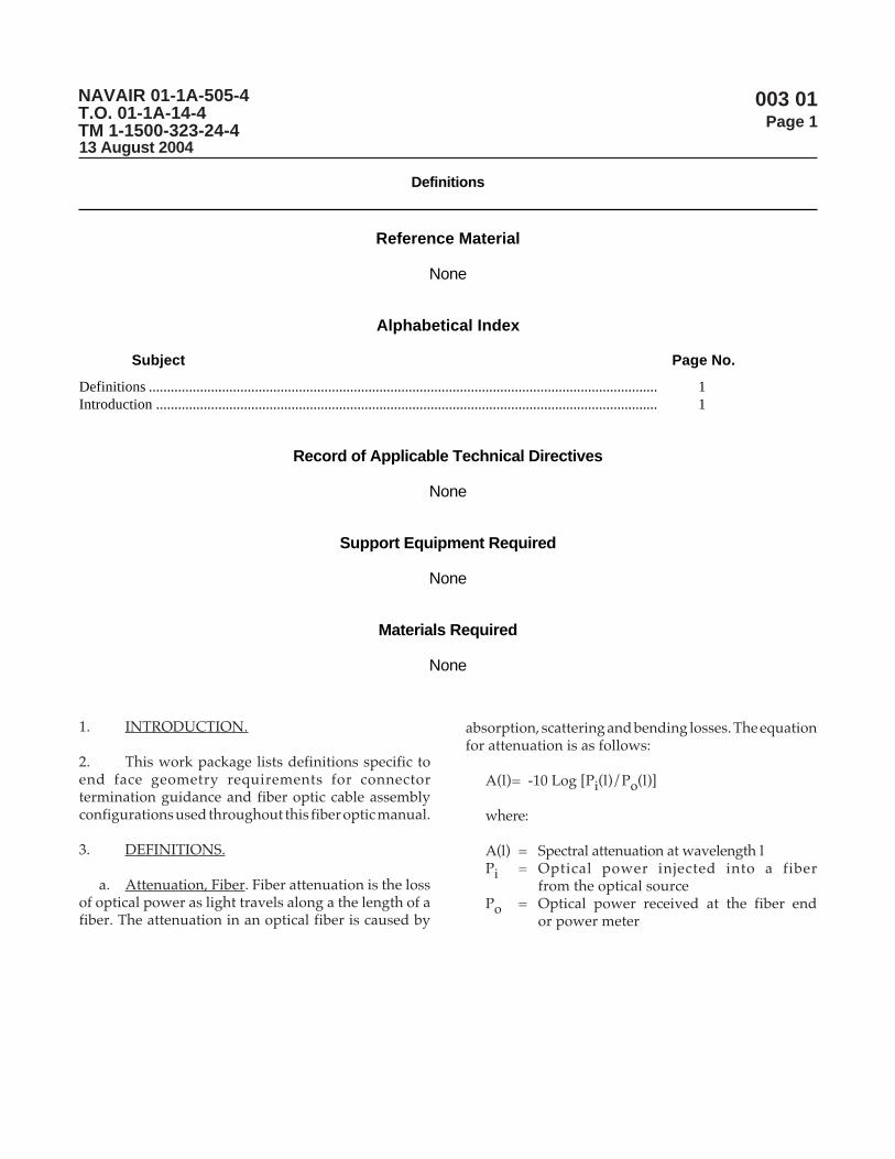
bl. Multiplexing. A method employed to transmitmultiple signals simultaneously over a singlecommunications link.
bm.Multiplexing, Wavelength Division. In opticalcommunication, any technique by which two or moreoptical signals having different wavelengths may besimultaneously transmitted in the same direction overone fiber (see Figure 5).
bn. Music Wire. See Piano Wire.
bo. Non-contact polish. See Polish, NC.
bp. Numerical aperture. The numerical aperture(NA) is a measurement of the ability of an optical fiberto capture light. The NA is also used to define theacceptance and emitting cone of an optical fiber.
bq. Offset. See Polish, Offset.
br. Offset, Angular. The angle between a radial linefrom the center of the spherical surface to the high pointof the polish and a line through the longitudinal axis inthe center of the fiber.
bs. Optical Fiber. A Optical fiber is a thin cylindricaldielectric (non-conductive) waveguide used to sendlight energy for communication. Optical fibers consistof three parts: the core, the cladding, and the coating orbuffer. The choice of optical fiber materials and fiberdesign depends on operating conditions and intendedapplication.
bt. Optical Fiber Cable. See Cable, Fiber Optic.
bu. Optical Fiber Cable Component (OFCC). AnOFCC is a buffered fiber augmented with a concentriclayer of strength members and an overall jacket. It isanother term to describe a tight buffed, single fibercable.
bv. Optical Fiber, Core. The core is located in thecenter of the optical fiber along the longitudinal axisand is bound by a cladding. It is the region with thehighest index of refraction and considered the lightconducting part of the fiber.
bw. Optical Fiber, Cladding. One or more layers ofmaterial, which surrounds the core of an optical fiber.It has a lower index of refraction when compared to thatof the core, thereby causing the transmitted light to becontained within the core.
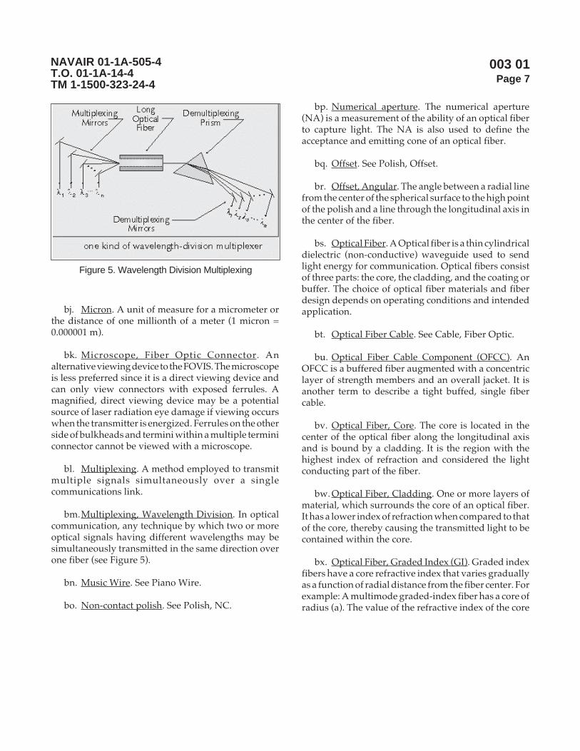
bx. Optical Fiber, Graded Index (GI). Graded indexfibers have a core refractive index that varies graduallyas a function of radial distance from the fiber center. Forexample: A multimode graded-index fiber has a core ofradius (a). The value of the refractive index of the core
Figure 5. Wavelength Division Multiplexing
NAVAIR 01-1A-505-4T.O. 01-1A-14-4TM 1-1500-323-24-4
003 01Page 8
(n1) decreases until it approaches the value of therefractive index of the cladding (n2). The value of n1must be higher than the value of n2 to allow for propermode propagation. The refractive index profile for amultimode graded-index fiber is shown in Figure 6.
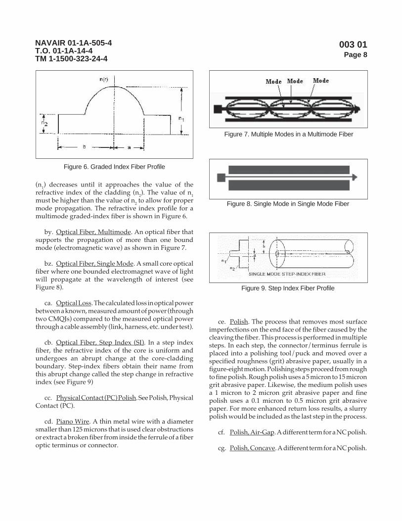
by. Optical Fiber, Multimode. An optical fiber thatsupports the propagation of more than one boundmode (electromagnetic wave) as shown in Figure 7.
bz. Optical Fiber, Single Mode. A small core opticalfiber where one bounded electromagnet wave of lightwill propagate at the wavelength of interest (seeFigure 8).
ca. Optical Loss. The calculated loss in optical powerbetween a known, measured amount of power (throughtwo CMQJs) compared to the measured optical powerthrough a cable assembly (link, harness, etc. under test).
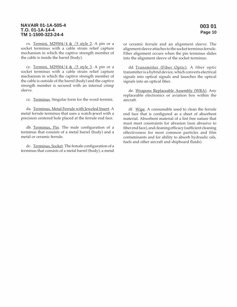
cb. Optical Fiber, Step Index (SI). In a step indexfiber, the refractive index of the core is uniform andundergoes an abrupt change at the core-claddingboundary. Step-index fibers obtain their name fromthis abrupt change called the step change in refractiveindex (see Figure 9)
cc. Physical Contact (PC) Polish. See Polish, PhysicalContact (PC).
cd. Piano Wire. A thin metal wire with a diametersmaller than 125 microns that is used clear obstructionsor extract a broken fiber from inside the ferrule of a fiberoptic terminus or connector.
ce. Polish. The process that removes most surfaceimperfections on the end face of the fiber caused by thecleaving the fiber. This process is performed in multiplesteps. In each step, the connector/terminus ferrule isplaced into a polishing tool/puck and moved over aspecified roughness (grit) abrasive paper, usually in afigure-eight motion. Polishing steps proceed from roughto fine polish. Rough polish uses a 5 micron to 15 microngrit abrasive paper. Likewise, the medium polish usesa 1 micron to 2 micron grit abrasive paper and finepolish uses a 0.1 micron to 0.5 micron grit abrasivepaper. For more enhanced return loss results, a slurrypolish would be included as the last step in the process.
cf. Polish, Air-Gap. A different term for a NC polish.
cg. Polish, Concave. A different term for a NC polish.
Figure 6. Graded Index Fiber Profile
Figure 7. Multiple Modes in a Multimode Fiber
Figure 8. Single Mode in Single Mode Fiber
Figure 9. Step Index Fiber Profile

NAVAIR 01-1A-505-4T.O. 01-1A-14-4TM 1-1500-323-24-4
003 01Page 9
ch. Polish, Non-Contact (NC). Ferrule end face ispolished in a manner so that the ferrules are the first tomake contact when connection surfaces are matedtogether without the fibers coming into contact.
ci. Polish, Offset. The polish offset is the distancebetween the highest point on the connector end face(where the center of the bull’s eye pattern is observed)and the center of the fiber. This offset is also referred toas the linear offset, eccentricity or apex offset.
cj. Polish, Physical Contact (PC). Ferrule end face ispolished in a manner so that the fibers are the first tomake contact when connection surfaces are matedtogether.
ck. Polishing Tool (Puck). A fixture used in thepolishing process to hold the ferrule of a single ferruleconnector or a terminus so that ferrule end face isperpendicular to and extends below the fixture’s flatbottom.
cl. Polyimide. High temperature thermoplasticresin used to coat optical fiber. Chosen because of itsexceptional mechanical, electrical and environmentalsurvivability properties.
cm. Radius of Curvature, Domed End Face. Anideally polished connector end face should have thefiber and the connector form a uniform, spherical surfacewith the fiber at the highest point (apex). The radius ofthis sphere formed by the polished connector is calledthe radius of curvature.
cn. Receiver, Fiber Optic. A fiber optic receiver is anelectro-optic device that accepts optical signals from anoptical fiber and converts them into electrical signals.
co. Refraction. The change in direction of light wavethat occurs when it passes from one medium into amedium having a different velocity of propagation (thespeed waves can travel through a medium).
cp. Refractive Index. See Index of Refraction.
cq. Splice. A permanent (as opposed to mateable)fiber joint that connects two optical fibers and exhibitslow loss optical performance. A means to repair opticalfibers damaged during installation, accident or stress.Two broad types of splices are mechanical and fusion.
cr. Splice, Fusion. Two optical fibers are melted orfused together by means of a fusion splice apparatususing such methods as electric arc, laser or gas flame.During fusion, the surface tension of molten glass tendsto realign the fibers on their outside diameter, changingfusion splicer initial alignments performed. As a result,a small core distortion may be present. Fusion spliceoperators must be highly trained and remain proficientto make low-loss, reliable fusion splices. Fusion splicingyields depend on the strength and loss requirements.Factors affecting splicing yields include condition ofthe splicing machine, personnel experience andenvironmental conditions.
cs. Splice, Mechanical. Two optical fibers are heldin alignment for an indefinite period without movementby means of a mechanical fixture (such as a tube/capillary, rods or v-groove substrate). Precision cleaveson the fiber ends and index matching fluid is used astwo measures to ensure low optical loss.
ct. Swab. A consumable used to clean the ferruleend face that is configured as an absorbent materialplaced on the end of a stick or dowel. Absorbent materialof a lint free nature that must meet constraints forgeometry (such as the cylindrical diameter be smallerthan 1.25 mm), abrasion (non abrasive to fiber end face),and cleaning efficacy (sufficient cleaning effectivenessfor most common particles and film contaminants andfor ability to absorb hydraulic oils, fuels and otheraircraft and shipboard fluids).
cu. Termination. The act of placing a fiber opticterminus or connector onto the end of a fiber opticcable.
cv. Termini. A fiber optic connection componentthat is inserted into one of the insert cavity of a multipletermini connector and terminated onto the end of asimplex, fiber optic cable. Plural form for the wordterminus.
cw. Termini, M29504/4 & /5 Style 1. A pin or asocket terminus with a cable strain relief capturemechanism in which the captive strength member ofthe cable is outside of the barrel (body). A piece ofshrink sleeve is placed over the captive strength member.
NAVAIR 01-1A-505-4T.O. 01-1A-14-4TM 1-1500-323-24-4
003 01Page 10
cx. Termini, M29504/4 & /5 style 2. A pin or asocket terminus with a cable strain relief capturemechanism in which the captive strength member ofthe cable is inside the barrel (body).
cy. Termini, M29504/4 & /5 style 3. A pin or asocket terminus with a cable strain relief capturemechanism in which the captive strength member ofthe cable is outside of the barrel (body) and the captivestrength member is secured with an internal crimpsleeve.
cz. Terminus. Singular form for the word termini.
da. Terminus, Metal Ferrule with Jeweled Insert. Ametal ferrule terminus that uses a watch-jewel with aprecision centered hole placed at the ferrule end face.
db. Terminus, Pin. The male configuration of aterminus that consists of a metal barrel (body) and ametal or ceramic ferrule.
dc. Terminus, Socket. The female configuration of aterminus that consists of a metal barrel (body), a metal
or ceramic ferrule and an alignment sleeve. Thealignment sleeve attaches to the socket terminus ferrule.Fiber alignment occurs when the pin terminus slidesinto the alignment sleeve of the socket terminus.
dd. Transmitter (Fiber Optic). A fiber optictransmitter is a hybrid device, which converts electricalsignals into optical signals and launches the opticalsignals into an optical fiber.
de. Weapons Replaceable Assembly (WRA). Anyreplaceable electronics or aviation box within theaircraft.
df. Wipe. A consumable used to clean the ferruleend face that is configured as a sheet of absorbentmaterial. Absorbent material of a lint free nature thatmust meet constraints for abrasion (non abrasive tofiber end face), and cleaning efficacy (sufficient cleaningeffectiveness for most common particles and filmcontaminants and for ability to absorb hydraulic oils,fuels and other aircraft and shipboard fluids).

NAVAIR 01-1A-505-4T.O. 01-1A-14-4TM 1-1500-323-24-4
003 02Page 1
Symbols
Reference Material
None
Alphabetical Index
Subject Page No.
Introduction ......................................................................................................................................... 1Symbols ............................................................................................................................................... 1
Record of Applicable Technical Directives
None
Support Equipment Required
None
Materials Required
None
1. INTRODUCTION.
2. This work package lists common symbols (schematicrepresentations) used in the electro-optics, photonics andfiber optic fields. These symbols are based on those listed inTIA-587.
3. SYMBOLS.
NOTE
Indicates the specific change in dB.
a. Amplifier, Optical.
NOTE
Indicates the specific change in dB.
b. Attenuator, Optical.
NOTE
Indicates the specific change in dB.
c. Attenuator, Variable, Optical.
13 August 2004

NAVAIR 01-1A-505-4T.O. 01-1A-14-4TM 1-1500-323-24-4
003 02Page 2
NOTE
Indicates the specific change in dB.
d. Attenuator, Within a Connector Assembly,Optical.
NOTE
If no confusion arises, then the symbol denotingfiber optics may be deleted.
e. Cable, Simplex Fiber Optic (or Optical Fiber).
NOTE
Composite cable shown contains followingsupplementary information:
4 copper conductors12 optical fibers with core diameter = 62.5 microns,clad diameter = 125 micronsNA = 0.27 (optional)
f. Cable, Composite.
NOTE
Male to female connection shown.
g. Connector, Plug-to-Receptacle Type, Optical.
NOTE
"NC" or "PC" can be added. (NC = non-contact.PC = physical contact).
h. Connector, Male-to-Male with Mating AdapterType, Optical.
NOTE
Four channel configuration shown.
i. Demultiplexer, Wavelength (WDM).
NOTE
Use with other symbols to denote fiber optics.
j. Denotation for a Fiber Optic Component.

NAVAIR 01-1A-505-4T.O. 01-1A-14-4TM 1-1500-323-24-4
003 02Page 3
NOTE
Four channel configuration shown.
k. Multiplexer, Wavelength.
l. Polarizer.
m. Polarization Controller.
n. Receiver.
o. Splice.
p. Splitter, Optical.
NOTE
n by m star coupler shown.
Change in dB may be placed in circle.
q. Star Coupler.
NOTE
1 by n switch shown.
r. Switch, Optical.
s. Transmitter.
Page 3/4 (Blank)

NAVAIR 01-1A-505-4T.O. 01-1A-14-4TM 1-1500-323-24-4
003 02Page 4
THIS PAGE LEFT INTENTIONALLY BLANK

NAVAIR 01-1A-505-4T.O. 01-1A-14-4TM 1-1500-323-24-4
003 03Page 1
Labels
Reference Material
None
Alphabetical Index
Subject Page No.
Introduction ......................................................................................................................................... 1Safety Labels ........................................................................................................................................ 1
Record of Applicable Technical Directives
None
Support Equipment Required
None
Materials Required
None
1. INTRODUCTION.
2. This work package lists labels that are approvedfor common, multi-service usage across aircraftplatforms.
3. SAFETY LABELS.
a. WRA Label.
Page 1/2 (Blank)
13 August 2004

NAVAIR 01-1A-505-4T.O. 01-1A-14-4TM 1-1500-323-24-4
003 03Page 2
THIS PAGE LEFT INTENTIONALLY BLANK

NAVAIR 01-1A-505-4T.O. 01-1A-14-4TM 1-1500-323-24-4
004 00Page 1
Safety and HAZMAT
Reference Material
None
Alphabetical Index
None
LIST OF SUBORDINATE WORK PACKAGES
SUBORDINATESUBJECT WORK PACKAGE DATESafety 004 01 13 August 2004HAZMAT 004 02 13 August 2004
Record of Applicable Technical Directives
None
1. INTRODUCTION.
2. This work package (WP) is divided into twosubordinate work packages for safety precautions andHAZMAT. The WP 004 01 for safety precautions liststhose that must be observed when working with fiberoptics. WP 004 01 is referenced in other work packages
for theory, handling, inspection, cleaning, fiber optictermination, testing and troubleshooting, assembly andinstallation. The WP 004 02 for Hazmat identifiesHAZMAT used in the fabrication (includingtermination) and cleaning of fiber optic cable topologies.WP 004 02 is referenced in other work packages fortroubleshooting, testing and installation.
Page 1/2 (Blank)
13 August 2004

NAVAIR 01-1A-505-4T.O. 01-1A-14-4TM 1-1500-323-24-4
004 00Page 2
THIS PAGE LEFT INTENTIONALLY BLANK

004 01Page 1
NAVAIR 01-1A-505-4T.O. 01-1A-14-4TM 1-1500-323-24-4
Safety
Reference Material
ANSI Z136.2
Alphabetical Index
Subject Page No.
Fiber Optic Safety Precautions ........................................................................................................... 2General Safety Precautions ................................................................................................................... 1Introduction ......................................................................................................................................... 1Laser Safety ......................................................................................................................................... 2
Record of Applicable Technical Directives
None
Support Equipment Required
None
Materials Required
None
1. INTRODUCTION. This work package lists thegeneral safety precautions that must be practiced whenworking with fiber optics. Other work packages willreference this one and may add to or emphasizeparticular safety precautions.
2. GENERAL SAFETY PRECAUTIONS. Thefollowing general safety precautions shall apply:
a. Observe and follow all written safety precautionsgiven in the methods of this and other work packagescontained within this manual.
b. Observe and adhere to all Warning/Caution/Advisory signs on equipment and materials.
c. Observe and adhere to all Warning/Caution/Advisories/Notes in the applicable Type/ Model/Series
13 August 2004
004 01Page 2
NAVAIR 01-1A-505-4T.O. 01-1A-14-4TM 1-1500-323-24-4
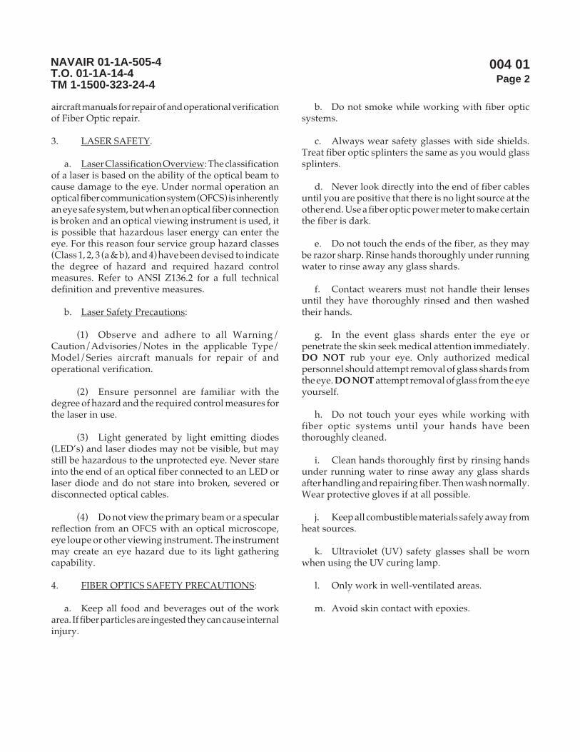
aircraft manuals for repair of and operational verificationof Fiber Optic repair.
3. LASER SAFETY.
a. Laser Classification Overview: The classificationof a laser is based on the ability of the optical beam tocause damage to the eye. Under normal operation anoptical fiber communication system (OFCS) is inherentlyan eye safe system, but when an optical fiber connectionis broken and an optical viewing instrument is used, itis possible that hazardous laser energy can enter theeye. For this reason four service group hazard classes(Class 1, 2, 3 (a & b), and 4) have been devised to indicatethe degree of hazard and required hazard controlmeasures. Refer to ANSI Z136.2 for a full technicaldefinition and preventive measures.
b. Laser Safety Precautions:
(1) Observe and adhere to all Warning/Caution/Advisories/Notes in the applicable Type/Model/Series aircraft manuals for repair of andoperational verification.
(2) Ensure personnel are familiar with thedegree of hazard and the required control measures forthe laser in use.
(3) Light generated by light emitting diodes(LED’s) and laser diodes may not be visible, but maystill be hazardous to the unprotected eye. Never stareinto the end of an optical fiber connected to an LED orlaser diode and do not stare into broken, severed ordisconnected optical cables.
(4) Do not view the primary beam or a specularreflection from an OFCS with an optical microscope,eye loupe or other viewing instrument. The instrumentmay create an eye hazard due to its light gatheringcapability.
4. FIBER OPTICS SAFETY PRECAUTIONS:
a. Keep all food and beverages out of the workarea. If fiber particles are ingested they can cause internalinjury.
b. Do not smoke while working with fiber opticsystems.
c. Always wear safety glasses with side shields.Treat fiber optic splinters the same as you would glasssplinters.
d. Never look directly into the end of fiber cablesuntil you are positive that there is no light source at theother end. Use a fiber optic power meter to make certainthe fiber is dark.
e. Do not touch the ends of the fiber, as they maybe razor sharp. Rinse hands thoroughly under runningwater to rinse away any glass shards.
f. Contact wearers must not handle their lensesuntil they have thoroughly rinsed and then washedtheir hands.
g. In the event glass shards enter the eye orpenetrate the skin seek medical attention immediately.DO NOT rub your eye. Only authorized medicalpersonnel should attempt removal of glass shards fromthe eye. DO NOT attempt removal of glass from the eyeyourself.
h. Do not touch your eyes while working withfiber optic systems until your hands have beenthoroughly cleaned.
i. Clean hands thoroughly first by rinsing handsunder running water to rinse away any glass shardsafter handling and repairing fiber. Then wash normally.Wear protective gloves if at all possible.
j. Keep all combustible materials safely away fromheat sources.
k. Ultraviolet (UV) safety glasses shall be wornwhen using the UV curing lamp.
l. Only work in well-ventilated areas.
m. Avoid skin contact with epoxies.
004 02Page 1
NAVAIR 01-1A-505-4T.O. 01-1A-14-4TM 1-1500-323-24-4
HAZMAT
Reference Material
49 CFR (Code of Federal Regulations), Parts 171-179
Alphabetical Index
Subject Page No.
Hazardous Material Transportation .................................................................................................... 1Hazardous Material Waste Disposal Control Measure ...................................................................... 2Introduction ......................................................................................................................................... 1
Record of Applicable Technical Directives
None
Support Equipment Required
None
Materials Required
None
1. INTRODUCTION.
2. This work package addresses guidelines for thetransportation and disposal of two-part epoxy (thosecurrently approved for use on aircraft and ships) and ofisopropyl alcohol used in fiber optic connectorterminations and cleaning procedures. Guidelines areprovided for disposal of fiber ends and consumable
materials used while working with epoxy also. Thisguidance is general and appropriate for most, if not allapplications. This guidance and the materials used arenot meant to be all-inclusive and must be augmented/tailored for each service being performed (installationor repair) and for variations in Local and Stateordinances. Consult your Activity HAZMAT Officerfor final guidance.
13 August 2004
004 02Page 2
NAVAIR 01-1A-505-4T.O. 01-1A-14-4TM 1-1500-323-24-4
3. HAZARDOUS MATERIAL TRANSPORTATION.
a. General. Two-part epoxy, as listed under thosecurrently approved for use on aircraft and ships, andisopropyl alcohol may be shipped by air transportationin limited quantities. Proper markings and labels mustbe present on the package. All shipping and labelingmust be in accordance with 49 CFR (Code of FederalRegulations), Parts 171-179. Site/Facility personneltrained for shipment of hazardous materials mustcomplete the hazardous material shipping forms andprovide/verify proper markings and labels on thepackage.
b. Transportation Information on MSDS. TheMaterial Safety Data Sheet written in the last five yearsmay contain transportation information. The USDOTor IATA ID number must be provided to determineallowable methods to ship the material.
c. Waste and Expired Shelf Life Materials.Arrangements must be made to have materials disposedof at the facility where the work is being done.
4. HAZARDOUS MATERIAL WASTE DISPOSALCONTROL MEASURES.
a. Two-Part Epoxy. Two-part epoxies, as listedunder those currently approved for use on aircraft andships, come in packets separated into two parts, hardenerand resin. The hardener is a corrosive material. Thegelled epoxy becomes a piece of thermoset plastic andmay be disposed of as non-hazardous waste. Leftoverepoxy, that has been mixed, may be disposed of withthe non-hazardous waste once it is hardened. Some
types of two-part epoxies may need to be heated inorder to cure. If the hardener goes bad, then the epoxywill not gel and must be disposed of as hazardouswaste. Consult your Activity HAZMAT Officer forfinal guidance.
b. Fiber Ends. Preferred disposal for cleaved endsof optical fiber is to place them in a plastic bottle. Analternative means is to wrap the fiber in a layer of tape.The placement of fiber ends in a bottle is preferred sincetape wrapped fiber usually is deposited into local, trashcans. Personnel emptying these trash cans are not awareof the potential fiber hazard to their hands and maycompress trash or remove stuck tape by hand. Theplastic bottle should have a small neck (so fiber ends donot spill out easily if tipped over). Also, do not use asnap-off cap or cover (so fibers do not launch out of thebottle in the jerking motion of opening the bottle cap).
c. Isopropyl Alcohol. This is a landfill-banned item.Non-used alcohol, such as contaminated bottles, mustbe disposed of as hazardous waste. Consult yourActivity HAZMAT Officer for final guidance.
d. Consumable Material Containing Mixed, DriedEpoxy. Dispose of dirty rags, wipes, syringes and otherconsumable material containing mixed, dried epoxiesby placing them in a waste container.
e. Canned Liquidfied Gas for Microscopic Dusting.Product is under pressure. Do not puncture or incinerate.Disposal must comply with Federal, State and localregulations. Consult your Activity HAZMAT Officerfor final guidance.

005 00Page 1
NAVAIR 01-1A-505-4T.O. 01-1A-14-4TM 1-1500-323-24-4
Theory
Reference Material
None
Alphabetical Index
None
LIST OF SUBORDINATE WORK PACKAGES
SUBORDINATESUBJECT WORK PACKAGE DATETheory of Fiber Optic Link Operation 005 01 13 August 2004
Record of Applicable Technical Directives
None
1. INTRODUCTION.
2. This work package (WP) is divided intosubordinate work packages for fiber optic theory. Thefirst subordinate work package, WP 005 01 addressestheory of fiber optic link operation. Future workpackages are planned to address unique techniques tobe used for specific configurations.
Page 1/2 (Blank)
13 August 2004

005 00Page 2
NAVAIR 01-1A-505-4T.O. 01-1A-14-4TM 1-1500-323-24-4
THIS PAGE LEFT INTENTIONALLY BLANK
005 01Page 1
NAVAIR 01-1A-505-4T.O. 01-1A-14-4TM 1-1500-323-24-4
Theory of Fiber Optic Link Operation
Reference Material
Definitions ............................................................................................................................. WP 003 01Safety .................................................................................................................................... WP 004 01General Handling Practices .................................................................................................... WP 006 01Manual Cleaning Procedures ................................................................................................ WP 008 02General Practices for Cable Harness Installation .................................................................... WP 012 01Cable Harness Replacement/Repair Overview ...................................................................... WP 013 01
Alphabetical Index
Subject Page No.
Background .......................................................................................................................................... 2Characteristics of Aircraft Links ........................................................................................................... 3Components of Fiber Optic Links ......................................................................................................... 3Introduction .......................................................................................................................................... 2Link Loss Budget ................................................................................................................................. 3Link Loss Measurement ....................................................................................................................... 7Safety ................................................................................................................................................... 2Scope .................................................................................................................................................... 2
Record of Applicable Technical Directives
None
Support Equipment Required
None
Materials Required
None
13 August 2004

005 01Page 2
NAVAIR 01-1A-505-4T.O. 01-1A-14-4TM 1-1500-323-24-4
1. SCOPE. This WP provides basic supplementaryinformation on fiber optic theory relative to theoperation, support and maintenance of aircraft fiberoptic links. A formal self study course on fiber optics isthe Navy Electricity and Electronics Training Series,Module 24, Introduction to Fiber Optics. The scope ofthis WP is limited to fiber optic interconnect componentsbetween fiber optic transmitting units and fiber opticreceiving units. This WP does not address internalcomponents of fiber optic transmitter and fiber opticreceiver units.
2. BACKGROUND. Aircraft fiber optic linksrequire more rugged components than fiber optic landlinks. Fiber optic links in tactical aircraft require morerugged components than links installed in pressurecompensated aircraft cabins. Individual aircraftplatform programs are responsible for choosing fiberoptic components suitable for use in expectedenvironments. The components discussed herein arerepresentative of components that have been selectedfor use in aircraft applications.
3. INTRODUCTION. A simple, one fiber, onedirection, box to box fiber optic link is shown in Figure 1.The link consists of four component types. Fiber optictransmitters convert input signals from electrical tooptical (EO) and transmit light out. They transmitinfrared (IR) light generated from LED or laser diodesources. Fiber optic receivers convert input light fromoptical to electrical (OE) and transmit electronic signalsout. Typically, fiber optic transmitters and receivers arebundled together in one unit called a fiber optictransceiver. Fiber optic cable carries the light in anoptical glass channel from one end of the link to theother. Fiber optic connectors provide a mating interfacebetween fiber optic cables and fiber optic enableddevices.
4. SAFETY. Fiber optic links pose two primarysafety concerns.
a. Exposure to Glass. Exposed fiber optic glass is aphysical hazard. The exposed glass is easy to break.Once broken, small, sharp splinters can stick to andpenetrate the skin. Small chards can then easily betransferred from fingers to other vulnerable body partslike the eyes. Exposure of fiber optic glass by inadvertentcutting of fiber optic cables from tool usage or chafingmust be avoided. Aircraft fiber optic cables are
constructed with an outer jacket, a protective braidedfabric strength member and a buffer material to protectthe fiber. It is important to note that the glass inside afiber cable can be broken without damaging the outercable construction. This can be done with excessivelytight cable clamping and by greatly violating thespecified minimum bend radius of a fiber cable.Generally this type of broken fiber is not a physicalhazard until a repair is tried that could expose thebroken glass.
b. Exposure to IR Radiation. The other primarysafety concern posed by fiber optic links, is exposure ofeyes to IR radiation. Fiber optic transmitters transmit IRlight generated from either LED or laser diode sources.Fiber optic transmitters with laser light sources, and thedevices they are embedded in, are required to be labeledwith a Laser Hazard Classification if they fall within alaser hazard class. Devices not falling within a laserhazard class, such as LED light sources, may not belabeled as transmitters even though they may betransmitters of IR or visible light.
c. IR Exposure Scenarios. The most likely scenariofor eye exposure to occur is with unmated connectorsfrom a fiber optic capable device that is powered up.These devices may include fiber optic test equipment aswell as installed WRAs, LRMs and avionics boxes. IRradiation is not visible, so the only condition indicatingthat an unmated connector may be transmitting iswhether an associated unit is powered up. Therefore,maintainers should avoid starring into unmatedconnectors and should be aware when fiber optic capabledevices are powered up. Currently (2004), most if notall, aircraft fiber optic transmitters are rated as Class-1laser transmitters, or they are safe enough to not requirelabeled hazard classification. Class-1 laser transmittersare generally exempt from radiation hazard controlsduring operation and maintenance. Maintainershowever, need to be aware of applicable fiber optic
Figure 1. Simple Fiber Optic Link

005 01Page 3
NAVAIR 01-1A-505-4T.O. 01-1A-14-4TM 1-1500-323-24-4
transmitter classification ratings for fiber optic capableunits.
5. LINK LOSS BUDGET. Fiber optic links are not100% efficient sending light from a source to adestination. Every interconnect and component thatthe light passes through has some scattering loss andabsorption loss associated with it. Digital fiber opticlinks are generally designed to work within a link lossbudget including known losses (e.g. due to connectors,aging and environmental factors) and some unknownlosses. A link’s “margin” is designed to cover unknownlosses. A link margin of 3 dB is a reasonable designvalue that would allow a link to function if half of thelight is lost due to an unexpected condition. Anunexpected condition might be degraded performanceof a defective transmitter, receiver, cable or connector.
6. CHARACTERISTICS OF AIRCRAFT LINKS.Aircraft fiber optic links have several distinguishingcharacteristics. They are short (typically less than 300feet). They generally contain less than 5 cables in series.Fiber optic cable(s) may be bundled with the copperwire cable(s). The link loss (optical loss) of a "healthy"aircraft fiber optic link is dominated by the number ofseries connectors in the link rather than the losses dueto cable lengths. For comparison purposes, the opticalloss incurred passing through one mated connector ishigher than the loss incurred passing through a 500 footlength of fiber optic cable.
7. COMPONENTS OF FIBER OPTIC LINKS.
a. Fiber Optic Transmitters. Fiber optic transmittersare embedded within WRAs, LRMs, avionics units andtest equipment. Their purpose is to modulate the lightthey emit with a signal (digital or analog) they are totransmit. Within fiber optic transmitters, LED or laserdiode photo-emitters emit IR radiation. The photo-emitters within fiber optic transmitters are chosen forthe specific applications they are intended. Simple point-to-point or switched digital fiber optic links are morecost effectively implemented as multimode links.Wavelength multiplexed and high bandwidth analoglinks are implemented as single mode links. Multimodeand single mode fiber optic applications will usedifferent photo-emitters. Primary differences of photo-emitters include: type (laser diode or LED), IRwavelength (near IR to mid IR), output power
(microwatts to milliwatts) and optical launch (restrictedto overfilled).
(1) Fiber Optic Transmitters in Test Equipment.Test equipment functioning as fiber optic transmittersare called Optical Sources. Optical sources are used totest fiber optic links for optical loss measurements.These measurements are generally invalid orinconclusive when made with optical sources that donot have the appropriate characteristics for the linkthey are used to measure. Appropriate characteristicsinclude: fiber type (multimode or single mode), fibercore/clad size (various), source type (laser diode orLED), source wavelength (near IR to mid IR), sourcepower (microwatts to milliwatts) and optical launch(restricted to overfilled). Extreme care must be taken inchoosing appropriate optical sources for making opticalmeasurements of aircraft fiber optic links.
b. Fiber Optic Receivers. Fiber optic receivers arealso embedded within WRAs, LRMs, avionics unitsand test equipment. Within fiber optic receivers,photodetectors convert received light into electricalenergy. The photodetectors within receiving equipmentare chosen for the specific applications they are intended.Multimode and single mode fiber optic applicationswill likely use receivers with different photodetectors.Photodetectors vary by the size of their photosensitiveactive areas and their wavelength sensitivity (near IR tomid IR).
(1) Fiber Optic Receivers in Test Equipment.Test equipment with fiber optic receivers include powermeters for optical loss measurements. Fiber opticreceiver characteristics must be appropriate for boththe optical source used and the fiber optic link beingmeasured. These measurements are generally invalidor inconclusive when made with power meters that donot have the appropriate characteristics for the fiberoptic link they are used to measure and for the opticalsource in which they are used. Appropriatecharacteristics include: source wavelength (near IR tomid IR), and source power (microwatts to milliwatts).Extreme care must be taken in choosing appropriatepower meters for making optical measurements ofaircraft fiber optic links.
c. Fiber Optic Connectors. The most commonconnector chosen for use with aircraft fiber optic linksis the MIL-DTL-38999 Series-III connector. Figure 2

005 01Page 4
NAVAIR 01-1A-505-4T.O. 01-1A-14-4TM 1-1500-323-24-4
depicts an eight fiber, fiber optic link with MIL-DTL-38999 Series-III bulkhead and plug connectors. Theseconnectors are compatible with both electronic andfiber optic pins and sockets. Fiber optic pins and socketsare called fiber optic termini. Dirt, wear, or inadequateconnector tightening can interfere with the precisealignment requirements of fiber optic termini in fiberoptic connectors.
(1) Fiber Optic Termini. Fiber optic terminiprovide a low-loss, light transparent termination forfiber optic cable (see Figure 3). To be low-loss, the glassin a fiber optic termini is polished to be smooth, scratchfree and chip free. The surface topology or geometry isalso precisely controlled. Maintaining these polishedsurface characteristics and keeping them clean isessential to keeping a fiber optic link operational. Fiberoptic termini consist of a ferrule and a metal housing.When mated, in a connector, fiber optic termini arebutted together against their ferrule end faces. Theferrule has a precision central hole to hold the glassfiber. The glass fiber is bonded to the ferrule with anepoxy that is rated to withstand an expected airborneenvironment. The metal housing is bonded to the fiberoptic cable. Socket termini have a guide (alignment)sleeve that covers their ferrule. The fiber optic terminiused in MIL-DTL-38999 Series-III connectors are MIL-PRF-29504 termini. Two styles of these termini areshown in Figure 3. A primary differentiation betweenstyles is the cable strength member capture method.
(2) Termini End Face. The polished end of afiber optic termini is called an end face. Handheld tools(such as FOVIS) allow two dimensional, magnifiedinspection of fiber optic end faces, right at a fiber opticconnector. Three end face images from such a tool areshown in Figure 4. The lighted central area indicatesthe fiber core region. Note the core diameters. Thediameter of human hair (about 70 microns) iscomparable to the core sizes shown in the two end faceimages on the left.
(3) Termini Topography. The elevationdimension of an end face can not be witnessed in theFigure 4 images. The elevation dimension describes thesurface elevation topography of the glass and the ferrulesurfaces (alternately called end face geometry). The
Figure 3. Sample MIL-PRF-29504 Fiber Optic Termini,Pin and Socket Samples for 38999Series-III Connectors
Figure 2. 38999 Series-III Connectors, Part of anEight Fiber, Fiber Optic Link
ferrule surface elevation topography is usually domed(convex) but can be flat. Figure 5 shows two domedferrule end faces butted up against one another as theywould be in a mated connector. The glass (core andcladding) surface elevation topography can be domed(convex), or non-contact (concave).
Figure 4. Fiber End Face Images with Light in the CoresFrom Left to Right (Core/Clad Sizes in Microns)100/140(multimode), 62.5/125(multimode)and 9/125(single-mode)

005 01Page 5
NAVAIR 01-1A-505-4T.O. 01-1A-14-4TM 1-1500-323-24-4
(4) Polish. The surface elevation topography ofthe glass is set when a termini is polished. PhysicalContact (PC) or Non-Contact (NC) may be specified forthe fiber polish. The design intent of a PC polish is forthe glass cores of connectorized, mated termini to be inphysical contact. The PC polish is the dominant typeacross land, sea and air applictaions, however bothtypes are specified for use in aircraft today. Mating a PCpolished termini to a termini with a non-contact polishis a dissimilar configuration that is not recommended.Mated non-contact polished termini result in ferrule toferrule contact with a slight gap (typically less than1 micron) between the glass surfaces.
(5) Polishing Proceedure Controls. Polishingfiber end faces requires procedures with controls inthem to guarantee the resulting surface elevationtopography profile is within specification and the twodimensional, magnified images show acceptablysmooth, scratch free and chip free surfaces. This istypically a multi step process with strict, reliability andreproducibility requirements.
(6) Problem Areas. Fiber optic connectorsperform critical alignment tasks of minimizing axial,lateral and angular misalignment of fibers in matedconnectors. Examples of these three misalignment typesare depicted in Figure 6. Fiber optic termini are alsovery succeptable to accumulating dirt while connectorsare unmated (due to humidity, aerosols and airborneparticulate). This makes connectors a likely place tolook when a problem with a fiber optic link is suspected.
(a) Alignment. Axial misalignment (seeFigure 6) is most likely to occur when connectors arenot tightened properly. It leaves a gap between fibersthat lets light leak out and scatter away. The resultingloss will increase as the width of the gap increases. WithMIL-DTL-38999 Series-III connectors a visible redinspection ring indicates an inadequitely closedconnector. A small gap (1/16 of an inch) can cause a 20 dBloss which will fail any fiber optic link. A 20 dB loss isequivelent to an attenuation factor of 1/100. Lateral andangular misalignment are likely to be caused by agingof mechanical parts within connectors.
Figure 5. Physical Contact of Two Fiber Optic Termini(Note Glass and Ferrule Are in Contact)
Figure 6. Examples of Good and Poor Alignment inFiber Optic Connectors

005 01Page 6
NAVAIR 01-1A-505-4T.O. 01-1A-14-4TM 1-1500-323-24-4
CAUTION
Inspect, clean (if needed) and re-inspect aftercleaning a connector/terminus ferrule andmating instrument adapters/interfacesimmediately before each mating to ensureaccurate and reproducible results. Perform theinspection and cleaning per WP 008 02.
NOTE
The number one cause for an increased opticalloss, after an insufficiently tight connection, isdirt and film deposits. No single cleaningmethod has been found to date that willguarantee a clean end face on the ferrule.Magnified visual inspection together withcleaning is important, when practical. Visualinspection is done using a FOVIS.Recommended cleaning supplies are listed inWP 008 02.
(b) Dirt. Dirty fiber optic end faces on terminiand improperly tightened connectors are expected to bethe most likely causes of an intermittent or failed fiberoptic link on aircraft. Dirt can rapidly accumulate ontermini of an unmated connector due to moisture, aerosolsand particulate in the air. A piece of dirt completelycovering a half moon section of a core will cause a loss of3 dB (or half the light). While all of the light travels in thecore of a fiber, most of the light travels in the center of thecore. Therefore a spot covering much less than half thearea of the core can also cause a 3 dB loss, if it is in the centerof the core. A 3 dB loss can possibly fail a fiber optic link,if some aging has occurred and if the link’s design marginis small. Dirt is important to eliminate when it is discovered.Since connectorized, mated termini are always incompression, dirt left on an end face will become moredifficult to remove (and possibly cause damage) ifconnectors are re-mated without cleaning the dirt away.
d. Fiber Optic Cables. Fiber optic cables carry lightfrom fiber optic transmitters to fiber optic receivers. Athin optical fiber is packaged in larger diameter fiberoptic cable to make it more rugged and easier to handle.
(1) Fiber Construction. The optical transportcomponent of aircraft fiber optic cable is a glass strandconsisting of a glass core region that is concentrically
surrounded by a glass cladding region. Figure 4 showsfiber end face images with clearly distinct core andcladding regions for three different fiber sizeconfigurations.
(a) Optical Fiber Coating. Optical fiber intactical aircraft interconnect cables typically has a 10 to20 micron thick protective polyimide coating. Thecoating tolerates extreme temperatures and protectsthe glass fiber from penetration by moisture and othercontaminants. The coating is softer than the glass fiberand the ceramic ferrule. Optical fiber cables in avionicsunits or in pressurized aircraft installations may nothave this polyimide coating. Figure 7 shows a 100/140micron fiber with and without the coating. Thispermanent protective coating increases the overall fiberdiameter of a 100/140 micron fiber to 172 microns.
(2) TIR. Light is kept in the fiber core andcontinually reflected forward by maintaining a conditioncalled Total Internal Reflection (TIR). The conditionsrequired for TIR depend on a critical angle αc which isdetermined by the index of refraction property of thecore and clad materials. TIR fails when incident rays oflight impact the core/clad boundary at an angle lessthan the critical angle (See αc in Figure 9). Violation ofa fiber optic cable’s bending specification and localizedexternal stress on a fiber optic cable are the primaryreasons for TIR to fail.
Figure 7. Diameters: Core, Cladding and Coating,100/140 Fiber With and WithoutPolyimide Coating
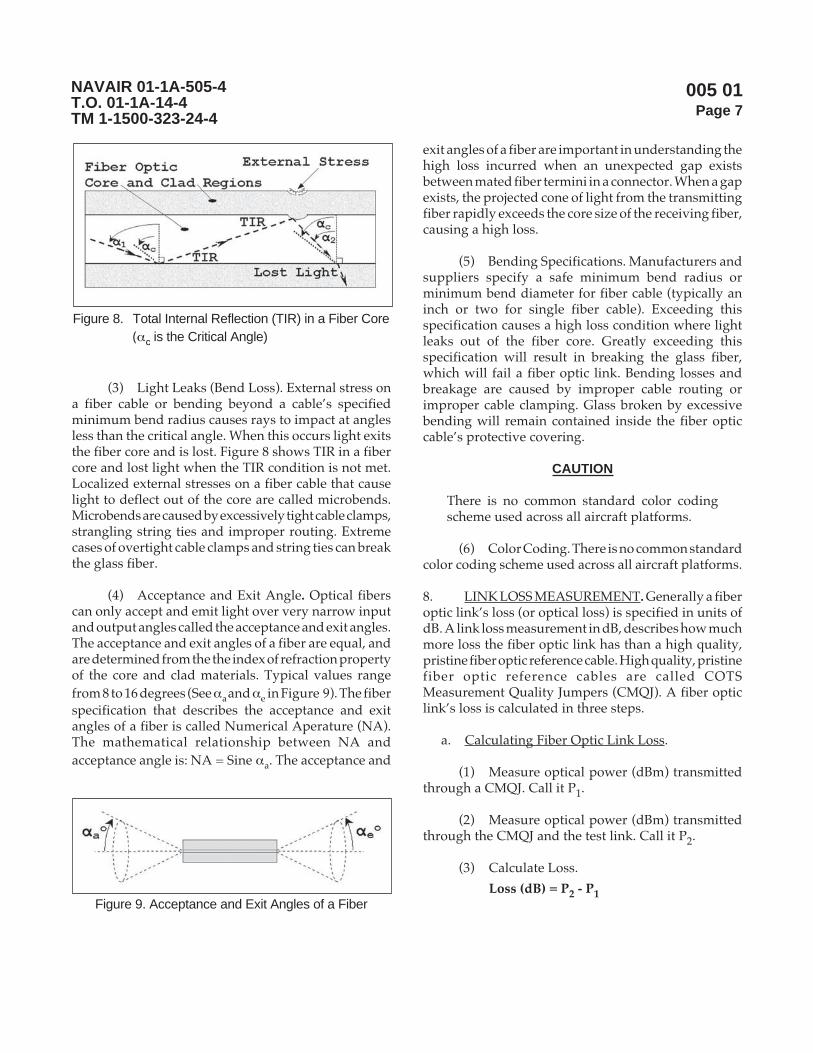
005 01Page 7
NAVAIR 01-1A-505-4T.O. 01-1A-14-4TM 1-1500-323-24-4
(3) Light Leaks (Bend Loss). External stress ona fiber cable or bending beyond a cable’s specifiedminimum bend radius causes rays to impact at anglesless than the critical angle. When this occurs light exitsthe fiber core and is lost. Figure 8 shows TIR in a fibercore and lost light when the TIR condition is not met.Localized external stresses on a fiber cable that causelight to deflect out of the core are called microbends.Microbends are caused by excessively tight cable clamps,strangling string ties and improper routing. Extremecases of overtight cable clamps and string ties can breakthe glass fiber.
(4) Acceptance and Exit Angle. Optical fiberscan only accept and emit light over very narrow inputand output angles called the acceptance and exit angles.The acceptance and exit angles of a fiber are equal, andare determined from the the index of refraction propertyof the core and clad materials. Typical values rangefrom 8 to 16 degrees (See αa and αe in Figure 9). The fiberspecification that describes the acceptance and exitangles of a fiber is called Numerical Aperature (NA).The mathematical relationship between NA andacceptance angle is: NA = Sine αa. The acceptance and
exit angles of a fiber are important in understanding thehigh loss incurred when an unexpected gap existsbetween mated fiber termini in a connector. When a gapexists, the projected cone of light from the transmittingfiber rapidly exceeds the core size of the receiving fiber,causing a high loss.
(5) Bending Specifications. Manufacturers andsuppliers specify a safe minimum bend radius orminimum bend diameter for fiber cable (typically aninch or two for single fiber cable). Exceeding thisspecification causes a high loss condition where lightleaks out of the fiber core. Greatly exceeding thisspecification will result in breaking the glass fiber,which will fail a fiber optic link. Bending losses andbreakage are caused by improper cable routing orimproper cable clamping. Glass broken by excessivebending will remain contained inside the fiber opticcable’s protective covering.
CAUTION
There is no common standard color codingscheme used across all aircraft platforms.
(6) Color Coding. There is no common standardcolor coding scheme used across all aircraft platforms.
8. LINK LOSS MEASUREMENT. Generally a fiberoptic link’s loss (or optical loss) is specified in units ofdB. A link loss measurement in dB, describes how muchmore loss the fiber optic link has than a high quality,pristine fiber optic reference cable. High quality, pristinefiber optic reference cables are called COTSMeasurement Quality Jumpers (CMQJ). A fiber opticlink’s loss is calculated in three steps.
a. Calculating Fiber Optic Link Loss.
(1) Measure optical power (dBm) transmittedthrough a CMQJ. Call it P1.
(2) Measure optical power (dBm) transmittedthrough the CMQJ and the test link. Call it P2.
(3) Calculate Loss.
Loss (dB) = P2 - P1
Figure 8. Total Internal Reflection (TIR) in a Fiber Core(αc is the Critical Angle)
Figure 9. Acceptance and Exit Angles of a Fiber
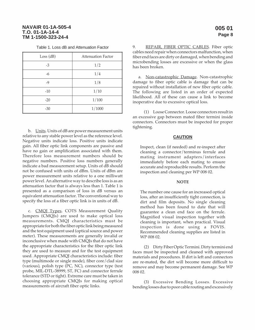
005 01Page 8
NAVAIR 01-1A-505-4T.O. 01-1A-14-4TM 1-1500-323-24-4
Table 1. Loss dB and Attenuation Factor
)Bd(ssoL rotcaFnoitaunettA
3- 2/1
6- 4/1
9- 8/1
01- 01/1
02- 001/1
03- 0001/1
b. Units. Units of dB are power measurement unitsrelative to any stable power level as the reference level.Negative units indicate loss. Positive units indicategain. All fiber optic link components are passive andhave no gain or amplification associated with them.Therefore loss measurement numbers should benegative numbers. Positive loss numbers generallyindicate a bad measurement setup. Units of dB shouldnot be confused with units of dBm. Units of dBm arepower measurement units relative to a one milliwattpower level. An alternative way to describe loss is as anattenuation factor that is always less than 1. Table 1 ispresented as a comparison of loss in dB versus anequivalent attenuation factor. The conventional way tospecify the loss of a fiber optic link is in units of dB.
c. CMQJ Types. COTS Measurement QualityJumpers (CMQJs) are used to make optical lossmeasurements. CMQJ characteristics must beappropriate for both the fiber optic link being measuredand the test equipment used (optical source and powermeter). These measurements are generally invalid orinconclusive when made with CMQJs that do not havethe appropriate characteristics for the fiber optic linkthey are used to measure and for the test equipmentused. Appropriate CMQJ characteristics include: fibertype (multimode or single mode), fiber core/clad size(various), polish type (PC, NC), connector type (testprobe, MIL-DTL-38999, ST, FC) and connector ferruletolerance (STD or tight). Extreme care must be taken inchoosing appropriate CMQJs for making opticalmeasurements of aircraft fiber optic links.
9. REPAIR, FIBER OPTIC CABLES. Fiber opticcables need repair when connectors malfunction, whenfiber end faces are dirty or damaged, when bending andmicrobending losses are excessive or when the glasshas been broken.
a. Non-catastrophic Damage. Non-catastrophicdamage to fiber optic cable is damage that can berepaired without installation of new fiber optic cable.The following are listed in an order of expectedlikelihood. All of these can cause a link to becomeinoperative due to excessive optical loss.
(1) Loose Connector. Loose connectors result inan excessive gap between mated fiber termini insideconnectors. Connectors must be inspected for propertightening.
CAUTION
Inspect, clean (if needed) and re-inspect aftercleaning a connector/terminus ferrule andmating instrument adapters/interfacesimmediately before each mating to ensureaccurate and reproducible results. Perform theinspection and cleaning per WP 008 02.
NOTE
The number one cause for an increased opticalloss, after an insufficiently tight connection, isdirt and film deposits. No single cleaningmethod has been found to date that willguarantee a clean end face on the ferrule.Magnified visual inspection together withcleaning is important, when practical. Visualinspection is done using a FOVIS.Recommended cleaning supplies are listed inWP 008 02.
(2) Dirty Fiber Optic Termini. Dirty termini endfaces must be inspected and cleaned with approvedmaterials and procedures. If dirt is left and connectorsare re-mated, the dirt will become more difficult toremove and may become permanent damage. See WP008 02.
(3) Excessive Bending Losses. Excessivebending losses due to poor cable routing and excessively

005 01Page 9
NAVAIR 01-1A-505-4T.O. 01-1A-14-4TM 1-1500-323-24-4
tight clamping (microbends), must be remedied bycable rerouting and adjustments to cable clamping. SeeWP 006 01 and WP 012 01.
(4) Unseated Fiber Optic Termini. Unseated pinor socket termini result in an excessive gap betweenmated fiber termini inside connectors. Termini must bereseated with the appropriate insertion tool.
(5) Damaged Connector. Damaged connectorscan cause misalignment of mated termini insideconnectors (See Figure 6). Connector damage due toaging and wear requires replacement of the connectorplug or receptacle.
b. Catastrophic Damage. Catastrophic damagerequires some new fiber cable to be installed. All of thefollowing can cause a link to become inoperative due toexcessive optical loss.
(1) Broken Glass Fiber. Repair is currentlylimited to installing a single replacement fiber opticcable. See WP 012 01 and WP 013 01.
(2) Scratched, Chipped End Face. Repair iscurrently limited to installing a single replacementfiber optic cable. See WP 012 01 and WP 013 01.
(3) Permanent Dirty End Face. Repair iscurrently limited to installing a single replacementfiber optic cable. See WP 012 01 and WP 013 01.
Page 9/10 (Blank)

005 01Page 10
NAVAIR 01-1A-505-4T.O. 01-1A-14-4TM 1-1500-323-24-4
THIS PAGE LEFT INTENTIONALLY BLANK

006 00Page 1
NAVAIR 01-1A-505-4T.O. 01-1A-14-4TM 1-1500-323-24-4
Handling
Reference Material
None
Alphabetical Index
None
LIST OF SUBORDINATE WORK PACKAGES
SUBORDINATESUBJECT WORK PACKAGE DATEGeneral Handling Practices for Fiber Optic Harnesses 006 01 13 August 2004
Record of Applicable Technical Directives
None
1. INTRODUCTION.
2. This work package (WP) is divided intosubordinate work packages for different types ofhandling guidance. The first subordinate work package,
WP 006 01, addresses general guidance for handlingfiber optic cable harnesses and components. Futurework packages are planned to address uniquetechniques to be used for specific configurations.
Page 1/2 (Blank)
13 August 2004

006 00Page 2
NAVAIR 01-1A-505-4T.O. 01-1A-14-4TM 1-1500-323-24-4
THIS PAGE LEFT INTENTIONALLY BLANK

006 01Page 1
NAVAIR 01-1A-505-4T.O. 01-1A-14-4TM 1-1500-323-24-4
General Handling Practices for Fiber Optic Cable Harnesses
Reference Material
Definitions ............................................................................................................................. WP 003 01Safety .................................................................................................................................... WP 004 01
Alphabetical Index
Subject Page No.
General Handling Practices ................................................................................................................... 2Connector/Termini Terminations ................................................................................................... 4Cable Bend Diameter Considerations ............................................................................................ 2General Summary.......................................................................................................................... 2Handling Do s and Don ts ............................................................................................................. 4Handling Practices Within the Aircraft .......................................................................................... 3Transporting .................................................................................................................................. 5
Introduction ......................................................................................................................................... 2
Record of Applicable Technical Directives
None
Support Equipment Required
None
Materials Required
None
13 August 2004

006 01Page 2
NAVAIR 01-1A-505-4T.O. 01-1A-14-4TM 1-1500-323-24-4
1. INTRODUCTION.
2. This work package provides general guidancefor handling fiber optic cable harnesses and components.The guidance includes cable bend diameterconsiderations, handling practices within the aircraft,placement with electrical cable, connector/terminiterminations, handling do’s and don’ts, andtransporting.
3. GENERAL HANDLING PRACTICES.
a. General Summary. Fiber optic cable harnessesand components must be handled with care. There ismuch similarity between the handling of optical fibercable and standard copper wiring harnesses. However,there are some unique differences requiring attentionwhen working in and around optical fiber cables. Thedegree of care involved in this handling is listed in thisWP. The next few statements are the key considerationsfor proper handling of optical fiber cables. They shouldbe taken into consideration whenever working on oraround cables containing optical fibers.
CAUTION
Inspect, clean (if needed) and re-inspect aftercleaning a connector/terminus ferrule andmating instrument adapters/interfacesimmediately before each mating to ensureaccurate and reproducible results. Perform theinspection and cleaning per WP 008 02.
NOTE
The number one cause for an increased opticalloss, after an insufficiently tight connection, isdirt and film deposits. No single cleaningmethod has been found to date that willguarantee a clean end face on the ferrule.Magnified visual inspection together withcleaning is important, when practical. Visualinspection is done using a FOVIS.Recommended cleaning supplies are listed inWP 008 02.
(1) Never bend fiber optic cables in excess ofthe minimum bend diameter.
(2) Always seek the largest possible benddiameter, when bending is necessary.
(3) Never fold fiber optic cable, or connectorson the cable, back over themselves.
(4) Never kink fiber optic cables. This will breakthe fiber.
(5) Never place fiber optic cable onto sharpbends.
(6) Always inspect and clean (see WP008 02)the connections prior to mating.
(7) Never excessively tighten or clamp fiberoptic cable. The degree of tightness must be snug.
(8) Never pry from clamps/straps, use as ahanger for tools/implements, or use as a hand hold/foot hold any installed cable, cable bundle or cableharness.
(9) Always cover connectors/termini withprotective covers (ESD or dust caps) immediately afterunmating (for any reason such as interval maintenanceor just to gain access).
b. Cable Bend Diameter Considerations.
(1) Minimum Bend Diameter. The minimumbend diameter is the diameter at which a cable or cableharness can be bent without degrading opticalperformance or the diameter at which a loose tubecable, convoluted tube or conduit can be bent withoutkinking (tube collapse causing fiber breakage). Twotypes of minimum bend diameters, short-term andlong-term bend diameters, must be considered.
(2) Short-term bend diameter. The short-termbend diameter applies during handling and installing.When the short-term bend diameter is not specified:
(a) Use a value of eight times the cablediameter for simplex, tight buffer cable (e.g. 2 mmdiameter for simplex type buffer cable results in a16 mm cable diameter. Also note that four times thecable diameter if working in terms of cable bend radius).

006 01Page 3
NAVAIR 01-1A-505-4T.O. 01-1A-14-4TM 1-1500-323-24-4
(b) Use a value of 20 times the cablediameter for simplex, loose tube cable (e.g. 2 mmdiameter loose tube cable results in a 40 mm cable benddiameter).
(c) Use a value of 20 times the tube diameterfor convoluted tube or conduit (e.g. 0.5 inch convolutedtubing results in a 10 inch cable bend diameter).
(3) Long-Term Bend Diameter. The long-termbend diameter applies to the completed installation.When the long-term bend diameter is not specified:
(a) Use a value of 16 times the cablediameter for simplex, tight buffer cable (i.e., eight timesthe cable diameter if working in terms of cable bendradius).
(b) Use a value of 20 times the cablediameter for simplex, loose tube cable.
(c) Use a value of 20 times the tube diameterfor convoluted tube or conduit.
c. Handling Practices Within the Aircraft.
(1) General Practice Tips.
(a) Bend diameter. Secure cables, cablebundles or cable harnesses as close as possible to theequipment without violating the long-term benddiameter.
(b) No external loading. Do not place anytension, compressive or bending force during handlingand placement of the cable, cable bundles or cableharness.
(c) Use of protective sleeve. Use protectivesleeves in locations where rubbing or sharp surfacescannot be avoided and rerouting is not practical. Do notuse protective sleeves in lieu of good routing practices.
(d) Use of Conduit. Guidance addressinginstallation of fiber optic cables and use of conduit iscovered in WP 011.
(e) Use of Over-braiding. Guidanceaddressing installation of fiber optic cables and use ofover-braid is covered in WP 011 01.
(f) Cable repair, remove and replace. Donot route replacement cable over any topology orobstruction that will place microbends into the cable.Microbends cause added loss.
(2) Placement in Cable Clamps.
(a) Insert cable into a cable clamp withoutdamaging the cable structure, excessively bending thecable, and without using excessive force. If possible,open the cable clamp and lay the portion of the cable,cable bundle or cable harness into the cable clamp. If theclamp can not be opened, pull the cable through theclamp applying the minimum amount of force andwithout damaging the cable structure. Do not pushfiber optic cable through a cable clamp.
NOTE
If a cushioned clamp (clamp with rubberchannel or insert) is used, then no sliding shouldbe evident when a moderate force is applied.Tighten cable, conduit and convoluted tube toconstrain without constricting. This is to ensurethat no deformation, kink or pinch will occur.Tighten cable wrap until constriction isobserved, but no deformation, kink or pinch isevident.
(b) Tightening of cable clamp. Tighten cableclamps to the degree that the cable is snug, but to theextent that cable does not deform, kink or pinch. Ensurethat the cable, cable bundle or cable harness will slide inthe clamp when a moderate force is applied.
1 Conduit and non-metallic conduit.Tighten to constrain without constricting. Constrictingthe conduit or non-metallic conduit will kink the tubestructure resulting in potential fiber breakage.
2 Cable wrap. Cable wrap may betightened to point of constriction since the constrictiondoes not create a hard point at which a kink will occur.
(3) Cable Slack.
(a) Ensure sufficient slack and strain reliefbetween equipment and the last point of cable support

006 01Page 4
NAVAIR 01-1A-505-4T.O. 01-1A-14-4TM 1-1500-323-24-4
for cable, cable bundles or cable harness entering hard-mounted equipment.
(b) Ensure an additional slack betweenequipment and the last point of cable support for cable,cable bundles or cable harness entering resilient orshock-mounted equipment that exceeds the traveldistance of the resilient or shock-mount.
(c) Ensure sufficient slack betweenmultiple termini connectors (such as the MIL-DTL-38999) attached to equipment and the last point of cablesupport for cable, cable bundles or cable harness.
(4) Placement with Electrical Cable.
(a) Supporting Cable. Ensure that opticalcables do not support electrical cables.
(b) Cable Position. Place fiber optic cables,cable bundles or cable harnesses on top of electricalcables where the two types are to be mixed in the samecable clamps.
(c) Installation Sequence. Install fiber opticcables, cable bundles or cable harnesses last whenmixed with electrical cables in the same cable clamp.
(d) Protective Coverings. Use protectivecoverings over the fiber optic cable, cable bundles orcable harness where the installation of electrical cablesover fiber optic cable, cable bundles or cable harnesscannot be avoided. Monitor the fiber optic cable duringthe electrical cable pull as an alternative to the use ofprotective coverings. Ensure that the fiber optic cable,bundles or cable harness does not support the electricalcable.
d. Connector/Termini Terminations.
(1) Stress at Termination Points. Handle cable,cable bundles or cable harnesses so as to prevent placingstresses on the connector/termini terminations. Therears of termini tend to be susceptible to breakage frommishandling such as sharp bends.
(2) Ferrule Protection. Keep dust covers orprotective caps on termini and connectors whenever
possible after unmating a connector.
(3) Connector Removal from Harness. Do notremove connectors during any operation involvingcable, cable bundle or cable harness handling wheneverpossible (this prevents cables within bundles fromrelaxing to a different length). Additionally, connectorremoval may result in an additional inspect and cleanoperation (see WP008 02) and the corresponding time ittakes.
(4) Pulling on Connector. Do not pull a fiberoptic cable harness using the connectors as a handle topull the cable. Take hold of the cables behind thebackshell with one hand and pull gently. Support theconnector with the other hand.
(5) Pulling on Cable in Direction Opposite ofConnector. Do not pull on the cable immediately afterthe backshell in the direction opposite to the connector.Such pulls cause terminus misalignment and cableshifts resulting in increased optical loss. Instead, firstrelease the connector on the end of the fiber optic cableand then support the connector as in (4) while pullingon the cable.
(6) Pulling on Termini. Do not pull a fiber opticcable bundle by the termini. Instead, take hold of thecables behind the termini with one hand and pullgently.
(7) Inserting Termini into Connector. Do notpermit cable immediately after termini to be bent,kinked, or folded over while inserting termini intoconnector. This is likely if insertion is attempted withoutuse of the proper insertion tool.
(8) MIL-DTL-38999 connector mating. Verifythat the red inspection ring is covered (not visible) asone measure for proper mating and that the connectoris tightened down completely.
e. Handling Do’s and Don’ts.
(1) Do’s.
(a) Do wear proper clothing and safetyequipment (gloves, eye protection, etc.) as appropriatewhile performing handling operations.

006 01Page 5
NAVAIR 01-1A-505-4T.O. 01-1A-14-4TM 1-1500-323-24-4
(b) Do use a step ladder properly(reposition versus leaning over) to conveniently accessfiber optic cables and connectors.
(c) Do pull slowly enough when installingcables so that you can readily notice if the cable getscaught.
(d) Do inspect and remove sharp edges,(including debris, burrs, etc. from bulkhead penetrationsand other items) along the route in which the cable willbe handled then placed.
(e) Do allow sufficient slack for ease ofmating connectors and adequate strain relief.
(f) Do keep ferrules/termini covered onceconnectors are unmated.
(g) Do inspect and clean (see WP008 02)ferrules/termini before mating connectors.
(h) Do use an insertion tool when insertingtermini into a connector.
(i) Do cover connectors/termini withprotective covers (ESD or dust caps) immediately afterunmating (for any reason such as interval maintenanceor just to gain access).
(2) Don’ts.
(a) Don’t exceed the minimum benddiameter.
(b) Don’t subject cables, cable bundles orcable harnesses to sharp bends.
(c) Don’t permit cables, cable bundles orcable harnesses to contact sharp edges.
(d) Don’t permit cables, cable bundles orcable harnesses to be kinked, folded over or crushed.
(e) Don’t permit cable immediately aftertermini to be bent or folded over while inserting terminiinto connector.
(f) Don’t permit cables or cable harnessesto be stretched for mating connectors.
(g) Don’t pry cables, cable bundles or cableharnesses.
(h) Don’t support your work items (tools,lamps, etc.) from cables, cable bundles or cable harnesses.
(i) Don’t use cables, cable bundles or cableharnesses as foot rests, steps or handholds.
(j) Don’t use any pointed object (like apencil) to count or otherwise contact ferrules/terminion/inside connectors. Similarly, don’t bring sharp toolsin contact with cables.
(k) Don’t clean ferrule end faces withoutinspecting them before and after cleaning.
f. Transporting.
(1) Place the cable, cable bundle or cable harnessin a coil that does not exceed the minimum benddiameter. Avoid bends, kinks and twisting.
(2) Support termini/connector ends andbreakout segments. Place on a backing material and tiedown. Tie the connectors and breakout segments to thecoil when no backing material is available.
(3) Wrap the cable, cable bundle or cable harnessin bubble paper.
(4) Place the cable, cable bundle or cable harnessin container large enough so that the cable, cable bundleor cable harness will lay flat without altering the shapeof the coils.
(5) Pick up the cable, cable bundle or cableharness by the coil, never by the connector or breakoutsegment.
(6) Isolate wrapped cable, cable bundle or cableharness during transportation to extent that no parts orequipment are stacked on top.


007 00Page 1
NAVAIR 01-1A-505-4T.O. 01-1A-14-4TM 1-1500-323-24-4
Troubleshooting
Reference Material
None
Alphabetical Index
None
LIST OF SUBORDINATE WORK PACKAGES
SUBORDINATESUBJECT WORK PACKAGE DATETroubleshooting Strategy 007 01 13 August 2004
Record of Applicable Technical Directives
None
13 August 2004
1. INTRODUCTION.
2. This work package (WP) is divided intosubordinate work packages for troubleshooting. Thefirst subordinate work package, WP 007 01 addresses
Troubleshooting Strategy. Future work packages areplanned to address unique troubleshooting techniquesto be used for specific configurations.
Page 1/2 (Blank)

007 00Page 2
NAVAIR 01-1A-505-4T.O. 01-1A-14-4TM 1-1500-323-24-4
THIS PAGE LEFT INTENTIONALLY BLANK

007 01Page 1
NAVAIR 01-1A-505-4T.O. 01-1A-14-4TM 1-1500-323-24-4
Troubleshooting Strategy
Reference Material
Definitions ............................................................................................................................. WP 003 01Safety .................................................................................................................................... WP 004 01General Handling Practices .................................................................................................... WP 006 01Inspection .............................................................................................................................. WP 008 01Manual Cleaning Techniques ................................................................................................ WP 008 02Optical Loss Measurement, Two Jumper ............................................................................... WP 009 01Fault Location Isolation Method Using OTDR ...................................................................... WP 009 05Fault Location Isolation Method Using Fault Finder .............................................................. WP 009 06
Alphabetical Index
Subject Page No.
Background .......................................................................................................................................... 2Failure Modes ....................................................................................................................................... 3Failure Modes, Likelihood .................................................................................................................... 7Failure Sites .......................................................................................................................................... 2Introduction .......................................................................................................................................... 2Scope .................................................................................................................................................... 2Strategy Flowchart ................................................................................................................................ 9Troubleshooting Tools .......................................................................................................................... 7Troubleshooting Tools Effectiveness .................................................................................................... 9
Record of Applicable Technical Directives
None
Support Equipment Required
None
Materials Required
None
13 August 2004

007 01Page 2
NAVAIR 01-1A-505-4T.O. 01-1A-14-4TM 1-1500-323-24-4
1. SCOPE. The scope of this troubleshootingstrategy is limited to passive fiber optic links (and theircomponents) between avionics boxes. This strategydoes not address active components such as fiber optictransceivers. Fiber optic transceivers typically residewithin avionics units. This WP provides intuitiveguidance to supplement other troubleshooting tools ofindividual aircraft platforms.
2. BACKGROUND. Limitations of system designs(Built-In-Test) and automated troubleshooting toolsmay only provide isolation of a fiber opticcommunication failure to a specific, single channel, boxto box, fiber optic link. This level of isolation does notdistinguish between failures of the fiber optictransmitting unit, the fiber optic interconnect hardwareor the fiber optic receiving unit. Troubleshooting isrequired determine whether the fiber optic link is atfault or whether associated WRAs, LRMs or avionicsunits are at fault. If the fiber optic link is at fault, furthertroubleshooting can isolate a fiber optic fault to a specificconnector, terminus or cable. If the fiber optic link is notat fault the maintainer will need to consider whetherthe fault lies within an avionics unit.
3. INTRODUCTION. The handling of fiber opticcables requires a high level of care similar to that usedwith coaxial Radio frequency (Rf) cables. Connectorsneed to be mated properly and cable bending must beregulated. Failures of fiber optic links will often beattributable to handling practices. Appropriate handlingpractices are covered in WP 006 01, which may besuperceded by the Platform maintenance manual. Afiber optic link has multiple possible failure sites andmodes. Efficiently narrowing down these possibilitiesto the specific cause of a failure, requires atroubleshooting strategy that considers failurelikelihood and the capabilities and effectiveness oftroubleshooting tools.
CAUTION
Inspect, clean (if needed) and re-inspect aftercleaning a connector/terminus ferrule andmating instrument adapters/interfacesimmediately before each mating to ensureaccurate and reproducible results. Perform theinspection and cleaning per WP 008 02.
NOTE
The number one cause for an increased opticalloss, after an insufficiently tight connection, isdirt and film deposits. No single cleaningmethod has been found to date that willguarantee a clean end face on the ferrule.Magnified visual inspection together withcleaning is important, when practical. Visualinspection is done using a FOVIS.Recommended cleaning supplies are listed inWP 008 02.
4. FAILURE SITES. Every interconnect and cablein a fiber optic link is a possible failure site. Thisincludes box mounted interconnects, intermediate cableinterconnects and every cable in a link (See Figure 1).Failures at these sites will likely be related to physicaldisturbances due to maintenance actions, either relatedor unrelated to the link with the reported problem.Unrelated maintenance actions may have disconnecteda fiber optic connector or pushed a fiber optic link cablejust to gain access to unrelated equipment. This canresult in dirt accumulating on exposed fiber optictermini, gapping between termini from inadequateconnector re-tightening and broken optical fiber in acable. Similarly, these same results can occur with theremoval and reinstallation of fiber optic enabled WRAs,LRMs and avionics units. The handling of fiber opticlink components requires vigilant adherence toappropriate handling practices. Appropriate handingpractices are covered in WP 006 01 which may besuperceded by the Platform maintenance manual.
a. Interconnects. Connectors are probably the mostlikely sites for fiber optic link failures. The most likelyconnector related problems that can cause a fiber opticlink failure are gapping between termini frominadequate connector re-tightening and dirtaccumulating on exposed fiber optic termini. When a
Figure 1. Failure Sites (A Single Channel,Box to Box, Fiber Optic Link)

007 01Page 3
NAVAIR 01-1A-505-4T.O. 01-1A-14-4TM 1-1500-323-24-4
loose fiber optic connector is found, all fiber optictermini shall be inspected and cleaned per WP 008 01and WP 008 02 before re-tightening.
b. Cables. Fiber optic Cables are susceptible todegraded performance and damage when appropriatehandling practices (see WP 006 01) are not followed.Fiber optic cables will become optically lossy as bendingexceeds bending specifications. The optical fiber incables will break when bending greatly exceeds bendingspecifications.
(1) Splices. Fiber optic splices installed inproduction manufactured cables are also possible failuresites. Prior to approval of a rugged, long-term usesplice, temporary fiber optic splices may be found insome aircraft. Fiber optic splices change cablecharacteristics because they are more rigid and have alarger diameter than aircraft fiber optic cable. Thesechanged cable characteristics make the fiber optic cableimmediately adjacent to the splice somewhat moresusceptible to breakage.
5. FAILURE MODES. Each failure site has multiplefailure modes. Fiber optic termini inside connectors canbecome unseated, dirty or damaged. Connectors maybe insufficiently tightened. Fiber optic termini may bemisaligned due to worn or aged connectors. Cables canbecome optically lossy due to excessive bending orclamping. The optical fiber inside cables can be brokenfrom excessive bending or clamping. The various failuremodes each have ranges of expected optical loss thatthey could cause. These ranges are notable for theirnarrowness, wideness, maximums and minimums. Theloss ranges estimated here are values that optical loss(link loss) test equipment can measure. Optical lossequipment can typically measure losses greater thanfifty dB. Operational fiber optic links in comparisonmay typically only be able to handle a few to ten dB ofloss. Table 1 Summarizes failure modes by likelihood,expected loss range and corrective action. A discussionof each failure mode follows.
Table 1. Summary of Failure Modes with Likelihood, Expected Optical Loss Range and Corrective Action
setiSeruliaF sedoMeruliaF doohilekiL noitcAevitcerroC
lacinahceM lacitpO)Bd(ssoL
inimreTelpitluMrotcennoC
)99983(
rotcennocdenethgityltneiciffusnI nepoot1.0 hgiH ,10800PWrepnaelc&tcepsnIetamerneht20800PW
ecafdneelurrefytriD 01ot1.0 hgiH ,10800PWrepnaelc&tcepsnIetamerneht20800PW
ecafdneelurrefdegamaD 03ot1.0 woL .rebiflacitporiapeR.10310PWdna10210PWeeS
inimretdetaesnU nepoot1 woL repnaelc&tcepsnI;taeseR.etamerneht20800PW,10800PW
,inimretdengilasiMstraprotcennocnrow
01ot1.0 woL rotcennocecalpeR
elbaC
:gnituorelbaCdetaloivretemaiddneB
3ot1.0 muideM .etuoreR.10210PWeeS
:gnipmalcelbaCthgitylevissecxE
3ot1.0 muideM .gunsekam:gnipmalcodeR.10210PWeeS
rebiflacitponekorB nepoot03 woL .rebiflacitporiapeR.10310PWdna10210PWeeS
ottnecajdarebiflacitponekorBfeilerniartsecilpsnoitcudorp
nepoot03 woL .rebiflacitporiapeR.10310PWdna10210PWeeS

007 01Page 4
NAVAIR 01-1A-505-4T.O. 01-1A-14-4TM 1-1500-323-24-4
a. Connector Failure Modes. Failure modes ofconnectors at WRAs, LRMs and avionics units as wellas intermediate connectors in a fiber optic link must beconsidered. Connectors at box interconnects must beevaluated on the box side as well as the cable plug end.Similarly, intermediate connectors, such as throughbulkhead connections, must be evaluated on the plugand receptacle sides.
CAUTION
Inspect, clean (if needed) and re-inspect aftercleaning a connector/terminus ferrule andmating instrument adapters/interfacesimmediately before each mating to ensureaccurate and reproducible results. Perform theinspection and cleaning per WP 008 02.
NOTE
The number one cause for an increased opticalloss, after an insufficiently tight connection, isdirt and film deposits. No single cleaningmethod has been found to date that willguarantee a clean end face on the ferrule.Magnified visual inspection together withcleaning is important, when practical. Visualinspection is done using a FOVIS.Recommended cleaning supplies are listed inWP 008 02.
NOTE
Fiber optic terminus shall be inspected andcleaned per WP 008 01 and WP 008 02, unlesssuperceded by the Platform maintenancemanual.
(1) Insufficiently Tightened Connector. Thismode is likely to occur whenever a connector isreconnected for any reason. When a loose fiber opticconnector is found, its fiber optic termini shall beinspected and cleaned per WP 008 01 and WP 008 02before re-tightening, unless superceded by the Platformmaintenance manual. A loose connector causes a gapbetween mated fiber optic termini. With a gap, theprojected cone of light from the transmitting fiber rapidlyexceeds the core size of the receiving fiber. Loosening aconnector behaves like a variable attenuator on the
Figure 2. A Connector Gap With Full Width of theInspection Line Visible (Top: ProperlyClosed Connector, Bottom: ImproperlyClosed Connector)
light sent from a transmitting termini to a receivingtermini. The loss attributed to this mode can be anythingfrom insignificant to greater than 50 dB (i.e. “opencircuit”). When the full width of the red inspection lineon a MIL-DTL-38999 connector is visible, the resultinggap for mated fiber optic termini pair could easily be aloss of 20 dB (See Figure 2).
(2) Dirty Fiber Optic Terminus/Ferrule. SeeFigure 3. When dirty fiber optic termini are found, theyshall be inspected and cleaned per WP 008 01 and WP008 02, unless superceded by the Platform maintenancemanual. A dirty terminus end face presents an opticalloss condition similar to dirt on a window. Dirt on awindow scatters light (making an image blurry) and

007 01Page 5
NAVAIR 01-1A-505-4T.O. 01-1A-14-4TM 1-1500-323-24-4
absorbs light (making an image dim). Dirt on matedfiber optic termini, scatters light away from the receivingcore and absorbs light going from core to core. Theresult is a loss that increases with the area, thicknessand density of the pollutant. Thick pollutants alsocause gaps between mated termini. Gaps allow light toescape before it can be collected by the core of a receivingfiber. The loss attributed to dirt on terminus end facescan typically be anything from insignificant to 10 dB forone mated termini pair. The inspection and cleaning offiber optic link components requires vigilant adherenceto appropriate inspection and cleaning practices.Appropriate inspection and cleaning practices arecovered in WP 008 01 and WP 008 02.
(3) Damaged Fiber Optic Terminus/Ferrule. SeeFigure 4. Damaged terminus end faces result frominadequate inspection and cleaning practices. Damagedterminus end faces require repair. Appropriateinstallation and repair practices are covered inWP 012 01 and WP 013 01, which may be superceded bythe Platform maintenance manual. Damaged terminusend faces can result when dirty termini are remated.Termini in fiber optic interconnects are always incompression. Soft dirt will tend to become permanentthe longer it is left. Hard dirt can cause permanentdamage like chips, scratches and cracks the first time aconnector is reconnected. The loss attributed to damagedterminus end faces can vary widely from insignificantto easily 30 dB for one mated termini pair. The inspectionand cleaning of fiber optic link components requiresvigilant adherence to appropriate inspection andcleaning practices. Appropriate inspection and cleaningpractices are covered in WP 008 01 and WP 008 02.
(4) Unseated Fiber Optic Terminus/Ferrule.Unseated termini that have been reseated, shall beinspected and cleaned prior to remating the connector.Unseated fiber optic termini can result from brokenretaining parts within connectors (See Figure 5) and ofthe termini assemblies themselves. An unseated terminican also be the result of an improper insertion of aterminus into a connector. The result of an unseatedterminus will be a gap between mated termini withadditional angular and lateral misalignment betweenthe mated termini (see Figure 6). The loss attributed toan unseated terminus will typically be large and mayrange from 10 dB to greater than 50 dB (i.e. "opencircuit").
Figure 3. Dirty End Faces
Figure 4. Damaged End Faces(Left: Crack in Cladding,Right: Permanent Dirt)
Figure 5. Damaged Retaining Parts FromWithin a MIL-DTL-38999 Connector
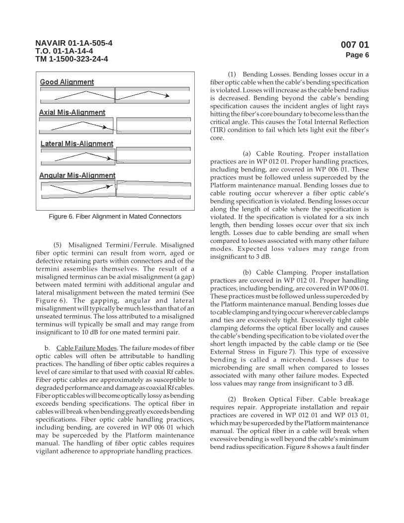
007 01Page 6
NAVAIR 01-1A-505-4T.O. 01-1A-14-4TM 1-1500-323-24-4
(5) Misaligned Termini/Ferrule. Misalignedfiber optic termini can result from worn, aged ordefective retaining parts within connectors and of thetermini assemblies themselves. The result of amisaligned terminus can be axial misalignment (a gap)between mated termini with additional angular andlateral misalignment between the mated termini (SeeFigure 6). The gapping, angular and lateralmisalignment will typically be much less than that of anunseated terminus. The loss attributed to a misalignedterminus will typically be small and may range frominsignificant to 10 dB for one mated termini pair.
b. Cable Failure Modes. The failure modes of fiberoptic cables will often be attributable to handlingpractices. The handling of fiber optic cables requires alevel of care similar to that used with coaxial Rf cables.Fiber optic cables are approximately as susceptible todegraded performance and damage as coaxial Rf cables.Fiber optic cables will become optically lossy as bendingexceeds bending specifications. The optical fiber incables will break when bending greatly exceeds bendingspecifications. Fiber optic cable handling practices,including bending, are covered in WP 006 01 whichmay be superceded by the Platform maintenancemanual. The handling of fiber optic cables requiresvigilant adherence to appropriate handling practices.
(1) Bending Losses. Bending losses occur in afiber optic cable when the cable’s bending specificationis violated. Losses will increase as the cable bend radiusis decreased. Bending beyond the cable’s bendingspecification causes the incident angles of light rayshitting the fiber’s core boundary to become less than thecritical angle. This causes the Total Internal Reflection(TIR) condition to fail which lets light exit the fiber’score.
(a) Cable Routing. Proper installationpractices are in WP 012 01. Proper handling practices,including bending, are covered in WP 006 01. Thesepractices must be followed unless superceded by thePlatform maintenance manual. Bending losses due tocable routing occur wherever a fiber optic cable’sbending specification is violated. Bending losses occuralong the length of cable where the specification isviolated. If the specification is violated for a six inchlength, then bending losses occur over that six inchlength. Losses due to cable bending are small whencompared to losses associated with many other failuremodes. Expected loss values may range frominsignificant to 3 dB.
(b) Cable Clamping. Proper installationpractices are covered in WP 012 01. Proper handlingpractices, including bending, are covered in WP 006 01.These practices must be followed unless superceded bythe Platform maintenance manual. Bending losses dueto cable clamping and tying occur wherever cable clampsand ties are excessively tight. Excessively tight cableclamping deforms the optical fiber locally and causesthe cable’s bending specification to be violated over theshort length impacted by the cable clamp or tie (SeeExternal Stress in Figure 7). This type of excessivebending is called a microbend. Losses due tomicrobending are small when compared to lossesassociated with many other failure modes. Expectedloss values may range from insignificant to 3 dB.
(2) Broken Optical Fiber. Cable breakagerequires repair. Appropriate installation and repairpractices are covered in WP 012 01 and WP 013 01,which may be superceded by the Platform maintenancemanual. The optical fiber in a cable will break whenexcessive bending is well beyond the cable’s minimumbend radius specification. Figure 8 shows a fault finder
Figure 6. Fiber Alignment in Mated Connectors
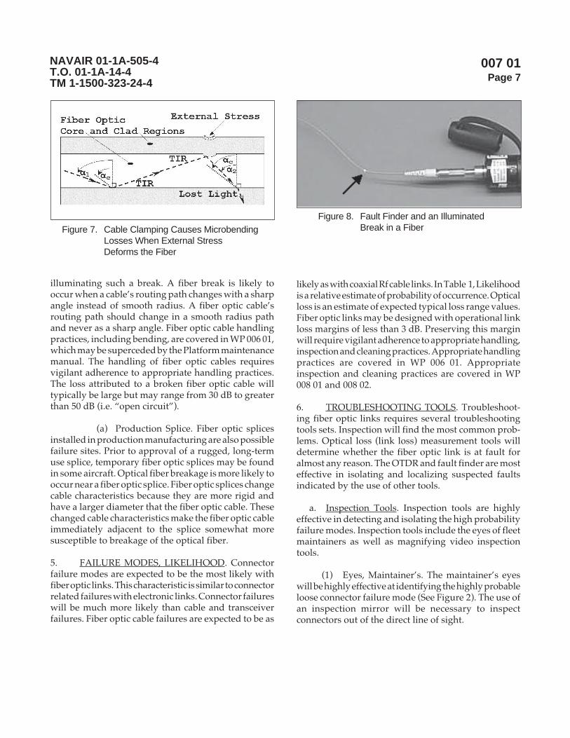
007 01Page 7
NAVAIR 01-1A-505-4T.O. 01-1A-14-4TM 1-1500-323-24-4
illuminating such a break. A fiber break is likely tooccur when a cable’s routing path changes with a sharpangle instead of smooth radius. A fiber optic cable’srouting path should change in a smooth radius pathand never as a sharp angle. Fiber optic cable handlingpractices, including bending, are covered in WP 006 01,which may be superceded by the Platform maintenancemanual. The handling of fiber optic cables requiresvigilant adherence to appropriate handling practices.The loss attributed to a broken fiber optic cable willtypically be large but may range from 30 dB to greaterthan 50 dB (i.e. “open circuit”).
(a) Production Splice. Fiber optic splicesinstalled in production manufacturing are also possiblefailure sites. Prior to approval of a rugged, long-termuse splice, temporary fiber optic splices may be foundin some aircraft. Optical fiber breakage is more likely tooccur near a fiber optic splice. Fiber optic splices changecable characteristics because they are more rigid andhave a larger diameter that the fiber optic cable. Thesechanged cable characteristics make the fiber optic cableimmediately adjacent to the splice somewhat moresusceptible to breakage of the optical fiber.
5. FAILURE MODES, LIKELIHOOD. Connectorfailure modes are expected to be the most likely withfiber optic links. This characteristic is similar to connectorrelated failures with electronic links. Connector failureswill be much more likely than cable and transceiverfailures. Fiber optic cable failures are expected to be as
likely as with coaxial Rf cable links. In Table 1, Likelihoodis a relative estimate of probability of occurrence. Opticalloss is an estimate of expected typical loss range values.Fiber optic links may be designed with operational linkloss margins of less than 3 dB. Preserving this marginwill require vigilant adherence to appropriate handling,inspection and cleaning practices. Appropriate handlingpractices are covered in WP 006 01. Appropriateinspection and cleaning practices are covered in WP008 01 and 008 02.
6. TROUBLESHOOTING TOOLS. Troubleshoot-ing fiber optic links requires several troubleshootingtools sets. Inspection will find the most common prob-lems. Optical loss (link loss) measurement tools willdetermine whether the fiber optic link is at fault foralmost any reason. The OTDR and fault finder are mosteffective in isolating and localizing suspected faultsindicated by the use of other tools.
a. Inspection Tools. Inspection tools are highlyeffective in detecting and isolating the high probabilityfailure modes. Inspection tools include the eyes of fleetmaintainers as well as magnifying video inspectiontools.
(1) Eyes, Maintainer’s. The maintainer’s eyeswill be highly effective at identifying the highly probableloose connector failure mode (See Figure 2). The use ofan inspection mirror will be necessary to inspectconnectors out of the direct line of sight.
Figure 7. Cable Clamping Causes MicrobendingLosses When External StressDeforms the Fiber
Figure 8. Fault Finder and an IlluminatedBreak in a Fiber

007 01Page 8
NAVAIR 01-1A-505-4T.O. 01-1A-14-4TM 1-1500-323-24-4
(2) Magnifying Video Inspection Tools.Magnifying video inspection tools are the only toolsthat can determine whether dirty or damaged end facesare at fault in a fiber optic link. Inspection beforecleaning determines if cleaning is necessary. Inspectionafter cleaning verifies cleaning effectiveness. Inspectionbefore reconnecting a replacement WRA, LRM or otheravionics unit avoids transferring dirt and possiblydamaging a mating connector. Inspection criteria forcleanliness and damage are covered in WP 008 01. A setof video inspection tools is shown in Figure 9.
b. Optical Loss Tools. Optical loss (link loss) toolsare excellent at determining whether the fiber optic linkis at fault. Isolating and localizing a detected problem toa particular failure mode of a link may require severalloss measurements or the use of other tools. Givenaccess to all connectors in a series of fiber optic cables,optical loss tools can determine which cable (if any) isat fault. Optical loss and inspection tools are a highlyproductive combination for isolating and localizing thegreat majority of failure modes. The usage of opticalloss tools are covered in WP 009 01. A set of optical losstools is shown in Figure 10.
c. Fault Finder. The fault finder is at best onlymoderately effective in locating an expected break ofthe optical fiber in a cable (See Figure 8). Locating abreak to within a few inches is a prerequisite toperforming a splice repair. Cable access, cable over-braiding and ambient light conditions all limit theeffectiveness of the fault finder (See Figure 11). The useof a fault finder tool is covered in WP 009 06.
d. OTDR. The Optical Time Domain Reflectometer(OTDR) is very effective in locating a break in a fiberoptic cable. Generally, back reflections from each cableinterconnect show up as narrow pulses on the OTDRdisplay (See Figure 12). When the distance between allcable interconnects are known, unexpected narrowpulses indicate a fiber break. Its primary drawback islimited availability due to its high cost. A secondaryconcern is that the user interface can be cumbersome,leading to ineffective usage.
Figure 10. Optical Loss Measurement Tools
Figure 9. Inspection Tools, Wipes and Swabs
Figure 11. Over-Braid Limits Effectiveness ofFault Finder
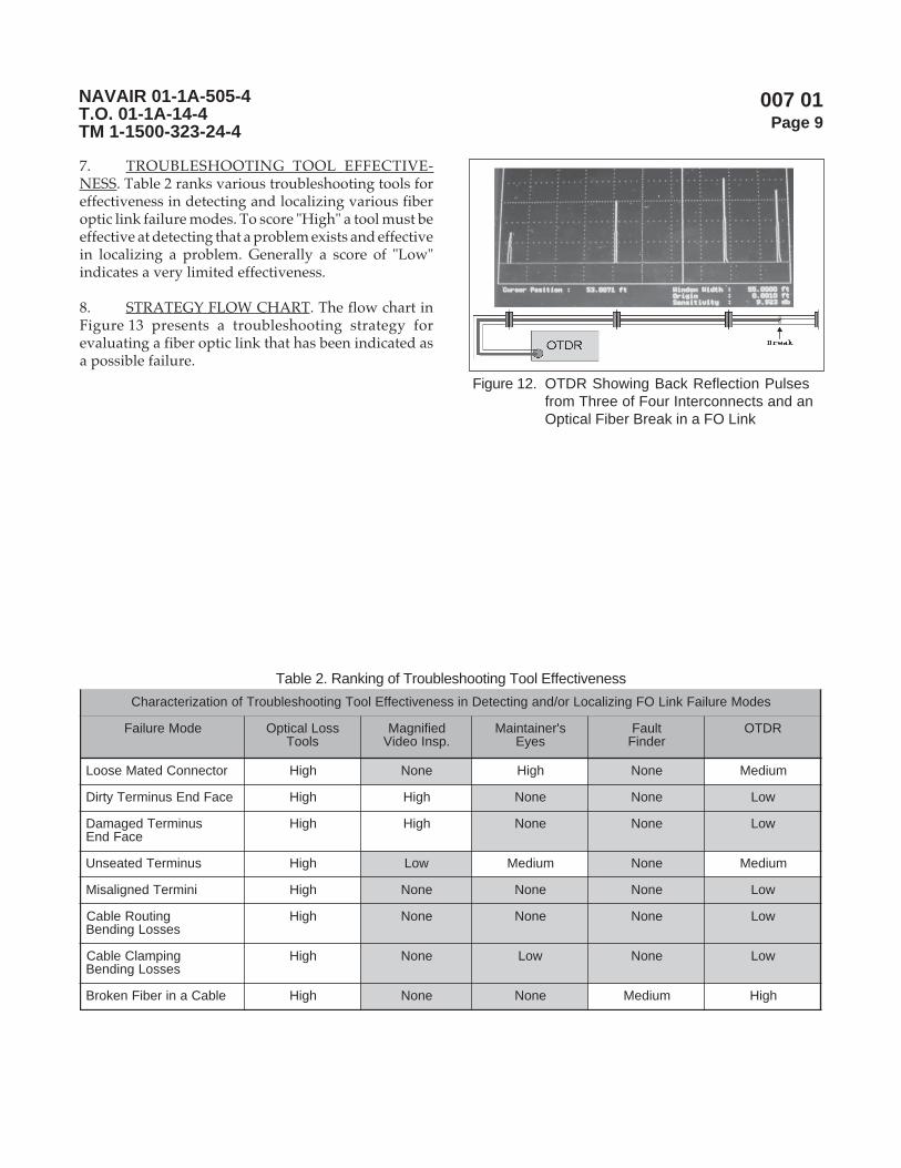
007 01Page 9
NAVAIR 01-1A-505-4T.O. 01-1A-14-4TM 1-1500-323-24-4
Figure 12. OTDR Showing Back Reflection Pulsesfrom Three of Four Interconnects and anOptical Fiber Break in a FO Link
Table 2. Ranking of Troubleshooting Tool Effectiveness
sedoMeruliaFkniLOFgnizilacoLro/dnagnitceteDnissenevitceffElooTgnitoohselbuorTfonoitaziretcarahC
edoMeruliaF ssoLlacitpOslooT
deifingaM.psnIoediV
s'reniatniaMseyE
tluaFredniF
RDTO
rotcennoCdetaMesooL hgiH enoN hgiH enoN muideM
ecaFdnEsunimreTytriD hgiH hgiH enoN enoN woL
sunimreTdegamaDecaFdnE
hgiH hgiH enoN enoN woL
sunimreTdetaesnU hgiH woL muideM enoN muideM
inimreTdengilasiM hgiH enoN enoN enoN woL
gnituoRelbaCsessoLgnidneB
hgiH enoN enoN enoN woL
gnipmalCelbaCsessoLgnidneB
hgiH enoN woL enoN woL
elbaCanirebiFnekorB hgiH enoN enoN muideM hgiH
7. TROUBLESHOOTING TOOL EFFECTIVE-NESS. Table 2 ranks various troubleshooting tools foreffectiveness in detecting and localizing various fiberoptic link failure modes. To score "High" a tool must beeffective at detecting that a problem exists and effectivein localizing a problem. Generally a score of "Low"indicates a very limited effectiveness.
8. STRATEGY FLOW CHART. The flow chart inFigure 13 presents a troubleshooting strategy forevaluating a fiber optic link that has been indicated asa possible failure.
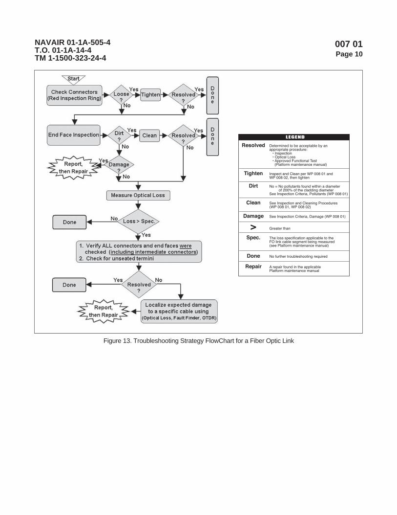
007 01Page 10
NAVAIR 01-1A-505-4T.O. 01-1A-14-4TM 1-1500-323-24-4
Figure 13. Troubleshooting Strategy FlowChart for a Fiber Optic Link
LEGEND
Resolved Determined to be acceptable by an appropriate procedure: • Inspection • Optical Loss • Approved Functional Test (Platform maintenance manual)
Tighten Inspect and Clean per WP 008 01 and WP 008 02, then tighten
Dirt No = No pollutants found within a diameter of 200% of the cladding diameterSee Inspection Criteria, Pollutants (WP 008 01)
Clean See Inspection and Cleaning Procedures (WP 008 01, WP 008 02)
Damage See Inspection Criteria, Damage (WP 008 01)
> Greater than
Spec. The loss specification applicable to the FO link cable segment being measured(see Platform maintenance manual)
Done No further troubleshooting required
Repair A repair found in the applicable Platform maintenance manual

008 00Page 1
NAVAIR 01-1A-505-4T.O. 01-1A-14-4TM 1-1500-323-24-4
General Inspection and Cleaning
Reference Material
None
Alphabetical Index
None
LIST OF SUBORDINATE WORK PACKAGES
SUBORDINATESUBJECT WORK PACKAGE DATEInspection 008 01 13 August 2004Manual Cleaning Procedures 008 02 13 August 2004
Record of Applicable Technical Directives
None
13 August 2004
1. INTRODUCTION.
2. This work package (WP) is divided intosubordinate work packages for inspection and differenttypes of cleaning processes and techniques. The firstsubordinate work package, WP 008 01, addressesinspection of ferrule end faces and presents criteria forcleanliness determination and damage determination.The second subordinate work package, WP 008 02,
addresses manual techniques using hand cleaningprocedures. These manual techniques are the ones incommon use today. Future work packages are plannedto address "powered" cleaning techniques, such as onusing a small, hand-held cleaning machine/device.This equipment is anticipated to reduce cleaning costand time while providing more consistent and betterresults.
Page 1/2 (Blank)

008 00Page 2
NAVAIR 01-1A-505-4T.O. 01-1A-14-4TM 1-1500-323-24-4
THIS PAGE LEFT INTENTIONALLY BLANK

008 01Page 1
NAVAIR 01-1A-505-4T.O. 01-1A-14-4TM 1-1500-323-24-4
Inspection
Reference Material
None
Alphabetical Index
Subject Page No.
Background .......................................................................................................................................... 4Introduction .......................................................................................................................................... 4Inspection Criteria, Damage ................................................................................................................. 8Inspection Criteria, Pollutants ............................................................................................................... 6
Acceptable .................................................................................................................................... 6Clean ............................................................................................................................................. 6Unacceptable ................................................................................................................................. 7
Inspection, Instrument Interface Ports ................................................................................................... 9Inspection Zones ................................................................................................................................... 5Purpose ................................................................................................................................................. 4When to Inspect .................................................................................................................................... 4
Record of Applicable Technical Directives
None
13 August 2004

008 01Page 2
NAVAIR 01-1A-505-4T.O. 01-1A-14-4TM 1-1500-323-24-4
metI noitpircseD ytitnauQ edoCegaC .oNgniyfitnedIrotraP 2/
TNEMPIUQETSET/NOITCEPSNIGNINAELC
NOITCEPSNIECAFDNEELURREF
711 esaco/wspiteborp/wtiKmetsySnoitcepsnIoediV)wolebsmetisedulcnitik( 1 7C8A3 A2-VAN-PBK
yalpsidrospiton,eborpnoitcepsnioediVX004/X002 1 7C8A3 1P-PBF
yalpsidoedivdlehdnah”5.2 1 7C8A3 1DH-PBF
sunimretnip4/40592MrofpiteborP 1 7C8A3 P2-LIM-TPBF
sunimrettekcos5/40592MrofpiteborP 1 7C8A3 S2-LIM-TPBF
elurref.aidmm5.2rofpiteborpdrochctaP 1 7C8A3 M52U-TPBF
elurref.aidmm52.1rofpiteborpdrochctaP 1 7C8A3 M21U-TPBF
retpadaTS-ot-TSurhtuv,piteborpretpadA 1 7C8A3 TS-TPBF
retpadaCS-ot-CSurhtuv,piteborpretpadA 1 7C8A3 CS-TPBF
retpadaCF-ot-CFurhtuv,piteborpretpadA 1 7C8A3 CF-TPBF
retpadaCL-ot-CLurhtuv,piteborpretpadA 1 7C8A3 CL-TPBF
retpadaeborprotcennoc99983M,piteborpretpadA 1 7C8A3 APC2-LIM-TPBF
1/
2/
tseTkniLlacitpO,tfarcriA,citpOrebiF,teStseT,2282167gniwarDAESVANrepdeificepsesohteraelbatsihtnismetI3.1.8.4RIAVANehthguorhtdevorppaeradnanidnuofeblliwsmetiesehtotsnoisiverynA.seirosseccA&tnempiuqE
.gniwardsihtrofssecorpecnatpecca.metiehtrofstnemeriuqerllufehtteemotdeifitnedineebevahtahtstcudorp'srerutcafunamroferadetsilsrebmuntraP
denimretedebotyitlibacilppA.tesehtgnittiftuorofstcudorptnelaviuqeecudorpotemoclewerasrerutcafunamrehtO.ssecorpmetsysylppuselbacilppaehthguorht
Support Equipment Required 1/

008 01Page 3
NAVAIR 01-1A-505-4T.O. 01-1A-14-4TM 1-1500-323-24-4
Materials Required 1/
metI noitpircseD ytitnauQ edoCegaC .oNgniyfitnedIrotraP 2/
)SROTCENNOCROF(SEILPPUSGNINAELCDRADNATS
101D )gnitsudcipocsorcim(sagdeifeuqildennaC4419643100586:NSN9117894100386:NSN
A/N 76212 0221SE
6FZ90 7053
201D etihw,gninaelchtolc,sepiW1976123100297:NSN
A/N 49912 404XT
00745 001-1532hceT
301D )lohoclarof(foorpkael,.zo4tnevlos,resnepsiD7635934105218:NSN
A/N 29033 4173
suordyhnaerup%99,lyporposI,lohoclA3156502005056:NSN
A/N 75716 61-3421-59300CDN
401D mm52.1,bawsgninaelC 05 00745 05-6132
04 12NL0 0090-21-SPCC
501D mm5.2,bawsgninaelC 05 00745 05-7132
04 12NL0 0090-52-SPCC
A/N 9741K 00400141
601D )05(stekcapdetarutas-erp,lohoclalyporposI,sepiW9566414100186:NSN
A/N
701D leeregdirtrac,sepiW 1 4BEW1 7226
191D hcuop)DOF(sirbeDtcejbOngieroF 6 6CR80 0203-0040
SEILPPUSGNINAELCETANRETLA/LATNEMELPPUS
202D )701Dmetirof(epatgninaelctnemecalpeR A/N 4BEW1 2326
302D eerfCFC,renaelctcatnoclacirtcelE A/N 42766 61130
1/
2/
tseTkniLlacitpO,tfarcriA,citpOrebiF,teStseT,2282167gniwarDAESVANrepdeificepsesohteraelbatsihtnismetI3.1.8.4RIAVANehthguorhtdevorppaeradnanidnuofeblliwsmetiesehtotsnoisiverynA.seirosseccA&tnempiuqE
.gniwardsihtrofssecorpecnatpecca.metiehtrofstnemeriuqerllufehtteemotdeifitnedineebevahtahtstcudorp'srerutcafunamroferadetsilsrebmuntraP
denimretedebotyitlibacilppA.tesehtgnittiftuorofstcudorptnelaviuqeecudorpotemoclewerasrerutcafunamrehtO.ssecorpmetsysylppuselbacilppaehthguorht

008 01Page 4
NAVAIR 01-1A-505-4T.O. 01-1A-14-4TM 1-1500-323-24-4
1. INTRODUCTION.
2. This work package is for inspection of the ferruleend face of a fiber optic connector or the ferrule end faceof each terminus in a fiber optic, multiple terminiconnector. Inspection is accomplished using a FiberOptic Video Inspection System (FOVIS) as shown inFigure 1. A FOVIS with 200X magnification will showapproximately a 600 micron wide x 450 micron higharea. Appropriate inspection criteria are presented thatmay be superceded by requirements of specific aircraftplatforms.
3. PURPOSE. The purpose of inspecting ferruleend faces is to look for pollutants and damage that mayaffect the passage of light between the cores of matedfiber optic termini. Inspections should cover the fibercore area, the fiber cladding area surrounding the coreand some of the ferrule surface area surrounding thecladding. Found damage, such as scratches, cracks orchips should be reported so that a repair can be initiated.Found pollutants should be cleaned using appropriatecleaning practices. Appropriate cleaning practices arecovered in WP 008 02, which may be superceded by thePlatform maintenance manual.
4. BACKGROUND. Pollutants on and damage toferrule end faces cause optical loss conditions that canfail a fiber optic link. Pollutants found on the corewould cause an optical loss condition due to absorptionand scattering of light. Pollutants found near the corecould also cause an optical loss condition because oftheir thickness. Thick pollutants cause gaps between
mated termini. These gaps allow light to escape beforeit can be collected by the core of a receiving fiber.Pollutants found near the core also present a risk ofcausing an optical obstruction the next time the fiberoptic termini are disturbed (see Figure 6, View C). Adisturbance, such as the next disconnect/re-connectevent, may be enough to move a pollutant from near thecore to over the core. The glass core, glass cladding andceramic ferrule areas are susceptible to scratches, cracksand chips. Scratches, cracks or chips in the core areacause an optical loss condition due to scattering of light.Exposing cracked or chipped glass cores, glass claddingand ceramic ferrule surfaces to flight conditions mayresult in sudden end face degradation resulting in asudden operational failure of the fiber optic link.
CAUTION
Inspect, clean (if needed) and re-inspect aftercleaning a connector/terminus ferrule andmating instrument adapters/interfacesimmediately before each mating to ensureaccurate and reproducible results. Perform theinspection and cleaning per WP 008 02.
NOTE
The number one cause for an increased opticalloss, after an insufficiently tight connection, isdirt and film deposits. No single cleaningmethod has been found to date that willguarantee a clean end face on the ferrule.Magnified visual inspection together withcleaning is important, when practical. Visualinspection is done using a FOVIS.Recommended cleaning supplies are listed inWP 008 02.
5. WHEN TO INSPECT. Inspection should alwaysbe done before mating any connector to verify all matingfiber optic ferrule end faces are clean and free of damage.Inspection detects ferrule end face pollutants anddamage. Existing pollutants and damage on an unmatedconnector (plug or receptacle) can easily be transferredto the mating connector.
a. Before and After Cleaning. Inspection is requiredbefore and after cleaning any ferrule end face (unlesssuperceded by the Platform maintenance manual).Cleaning an end face is not risk free. Cleaning materials
Figure 1. Fiber Optic Video Inspection System (FOVIS)

008 01Page 5
NAVAIR 01-1A-505-4T.O. 01-1A-14-4TM 1-1500-323-24-4
(such as swabs and wipes) can easily becomecontaminated with particulate. Contaminated cleaningmaterials used on a clean end face may leave it spotted.Inspection must always determine when terminicleaning is required and inspection must verify thatevery cleaning attempt was successful.
NOTE
Inspection and cleaning of ferrule end faces onreplacement WRA, LRM or other avionics unitsshould be done prior to carrying replacementunits out to an aircraft (especially on the flightdeck or flight line). This is highly importantwhen conditions (wind, rain, etc.) on the flightdeck or flight line may prohibit performance ofinspection and cleaning.
ESD caps or dust caps should be left on all fiberoptic connectors until cables are ready to beconnected to the replacement WRA, LRM orother avionics unit.
Always cover connectors (with ESD or dustcaps) immediately after unmating. Never usetape to cover connectors with fiber optic terminiin them.
b. Avionics Box Installation. Inspection should beperformed when replacing a WRA, LRM or otheravionics unit. Ferrule end faces on the replacement unitand the mating plug(s) must be inspected for pollutantsand damage prior to mating connectors with fiberoptics.
c. Troubleshooting Fiber Optic Link. Inspectionshould be performed in the process of troubleshootinga suspected fiber optic link problem. For example,before connecting any test equipment (such as CMQJs),the end faces on the equipment and the suspected cableends must be inspected.
6. INSPECTION ZONES. Damage inspection andpollutant inspection require the definition of severalzones of a ferrule end face image. A FOVIS ferrule endface image with 200X magnification will show an areaseveral times larger than the fiber core and cladding ofa 100/140 micron fiber. Figure 2 shows a ferrule endface with a polyimide coated 100/140 micron fiber. Thefull fiber diameter including the polyimide coating is
172 microns. Optical fiber cables installed in tacticalaircraft or in unpressurized compartments will typicallyhave polyimide coated fiber. Optical fiber cables withinavionics units or within pressurized aircraft cabins maynot have this polyimide coating.
a. Damage Inspection. Inspection for damageshould consider the full viewable area that the FOVISshows. Inspection must consider the glass core, glasscladding, polyimide coating (if present) and theviewable surface area of the ceramic ferrule. The glasscore, glass cladding and ceramic ferrule areas aresusceptible to scratches, cracks and chips, which areprimary concerns. A polyimide coating is softer thanthe glass fiber or the ceramic ferrule. Minor scratches,cracks and chips in the polyimide coating (if present)are not a concern. The primary concern with a polyimidecoating is that its general structural integrity remainsintact, providing support all around the fiber. Loosepieces of the polyimide coating are a pollution inspectionconcern.
(1) Damage Inspection Zone. The gross zonefor damage detection is the full viewable area that theFOVIS shows.
b. Pollutant Inspection. Inspection for pollutantsshould prioritize the fiber core area. Optical fiber isdesigned to transport light through the core. Pollutantson the core area will generally cause more loss thanpollutants found elsewhere. Pollutants found outside
Figure 2. 200X FOVIS Ferrule End Face with aPolyimide Coated 100/140 Fiber
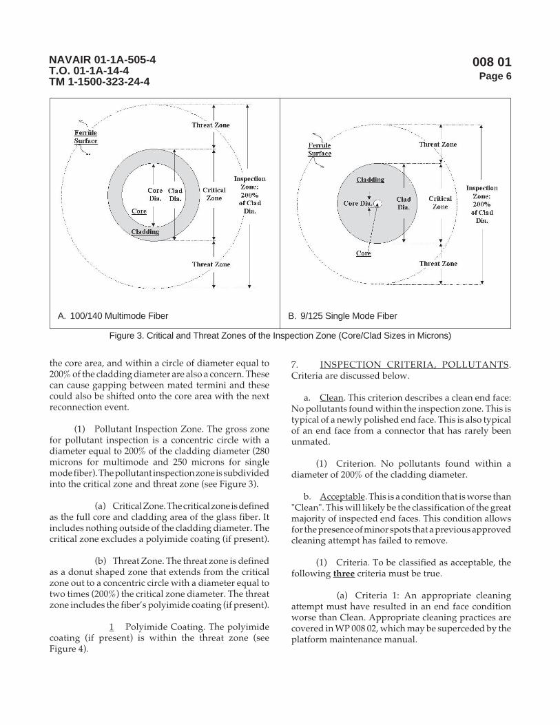
008 01Page 6
NAVAIR 01-1A-505-4T.O. 01-1A-14-4TM 1-1500-323-24-4
the core area, and within a circle of diameter equal to200% of the cladding diameter are also a concern. Thesecan cause gapping between mated termini and thesecould also be shifted onto the core area with the nextreconnection event.
(1) Pollutant Inspection Zone. The gross zonefor pollutant inspection is a concentric circle with adiameter equal to 200% of the cladding diameter (280microns for multimode and 250 microns for singlemode fiber). The pollutant inspection zone is subdividedinto the critical zone and threat zone (see Figure 3).
(a) Critical Zone. The critical zone is definedas the full core and cladding area of the glass fiber. Itincludes nothing outside of the cladding diameter. Thecritical zone excludes a polyimide coating (if present).
(b) Threat Zone. The threat zone is definedas a donut shaped zone that extends from the criticalzone out to a concentric circle with a diameter equal totwo times (200%) the critical zone diameter. The threatzone includes the fiber’s polyimide coating (if present).
1 Polyimide Coating. The polyimidecoating (if present) is within the threat zone (seeFigure 4).
Figure 3. Critical and Threat Zones of the Inspection Zone (Core/Clad Sizes in Microns)
A. 100/140 Multimode Fiber B. 9/125 Single Mode Fiber
7. INSPECTION CRITERIA, POLLUTANTS.Criteria are discussed below.
a. Clean. This criterion describes a clean end face:No pollutants found within the inspection zone. This istypical of a newly polished end face. This is also typicalof an end face from a connector that has rarely beenunmated.
(1) Criterion. No pollutants found within adiameter of 200% of the cladding diameter.
b. Acceptable. This is a condition that is worse than"Clean". This will likely be the classification of the greatmajority of inspected end faces. This condition allowsfor the presence of minor spots that a previous approvedcleaning attempt has failed to remove.
(1) Criteria. To be classified as acceptable, thefollowing three criteria must be true.
(a) Criteria 1: An appropriate cleaningattempt must have resulted in an end face conditionworse than Clean. Appropriate cleaning practices arecovered in WP 008 02, which may be superceded by theplatform maintenance manual.

008 01Page 7
NAVAIR 01-1A-505-4T.O. 01-1A-14-4TM 1-1500-323-24-4
(b) Criteria 2: No pollutants are foundwithin the critical zone, that by themselves orcumulatively, would obstruct more than 5% of the corearea. A circular 5% core area obstruction would have adiameter equal to 25% of the core diameter. Table 1 andFigure 5 present obstruction size reference information.Pollutant obstructions are not expected to be circular,however a circular illustration provides a practicalbasis for evaluating obstructed area.
(c) Criteria 3: No individual pollutants arefound within the threat zone, that by themselves couldobstruct more than 50% of the core area (if moved ontothe core). This condition allows more than one pollutant,as long as none of them would obstruct more than 50%of the core area. A circular 50% core area obstructionwould have a diameter equal to 70% of the core diameter.Figure 5 and Table 1 present obstruction size referenceinformation. Pollutant obstructions are not expected tobe circular, however a circular illustration provides apractical basis for evaluating obstructed area.
(2) Illustrative Areas. Table 1 presents diametersizes of illustrative circular areas that individually wouldblock 5% of the core area (25% of the core diameter) and50% of the core area (70% of the core diameter) for typicalfiber core diameters. A 5% core area obstruction couldresult in an approximate 0.25 dB loss. A 50% core areaobstruction could result in an approximate 3 dB loss.
(3) Illustrative Examples. Figure 5 shows scaled5% core area obstructions inside various core sizes.
c. Unacceptable. Unacceptable is defined asanything worse than that described as "acceptable".Any inspection classified as unacceptable, because of a
Figure 4. Polyimide Coating is in the Threat Zone
snoitcurtsbOaerAeroC%05dna%5nodesaBnoitcurtsbOralucriCevitartsullInarofsretemaiDnoitcurtsbOxaM
dalC/eroCrebiF)snorcim(.aiD
enoZlacitirC)snorcim(.aiD
enoZlacitirCnoitcurtsbOevitartsullIxaM
).aiDeroCfo%52()snorcim(.aiD
enoZtaerhT)snorcim(.aiD
enoZtaerhTnoitcurtsbOevitartsullIxaM
).aiDeroCfo%07()snorcim(.aiD
041/001 041 52 082 27
521/5.26 521 61 052 44
521/05 521 5.21 052 63
521/9 521 52.2 052 6
Table 1. Illustrative Circular Obstruction Sizes
Figure 5. Scaled 5% Core ObstructionsShown inside Cores of 100/140, 62.5/125and 9/125 End Face Sizes

008 01Page 8
NAVAIR 01-1A-505-4T.O. 01-1A-14-4TM 1-1500-323-24-4
A. Pollutants in Critical & Threat Zones B. Pollutants in Critical Zone C. Pollutants in Threat Zone
Figure 6. Unacceptable Polluted Samples (Pollutants Larger Than Maximum Size Allowed)
core obstruction, requires a loss measurement orapproved functional test (see Platform maintenancemanual) to ultimately determine the acceptability ofthe end face condition. Any inspection classified asunacceptable indicates additional cleaning should betried.
(1) Unacceptable Polluted Samples (seeFigure 6, Views A, B, and C).
8. INSPECTION CRITERIA, DAMAGE. Anyinspection detecting a crack or chip in the core area,cladding area or viewable ferrule surface area isunacceptable. In addition, scratches in the core area andcladding area are unacceptable as well. This damagemust be reported so that a repair can be initiated.Exposing cracked or chipped glass cores, glass claddingand ceramic ferrule surfaces to flight conditions mayresult in sudden end face degradation resulting in asudden operational failure of the fiber optic link. Minorscratches, cracks and chips in the polyimide coating (ifpresent) are not a concern. The primary concern with apolyimide coating is that its general structural integrityremains intact, providing support all around the fiber.Figure 7 presents sample sketches of some damagetypes.
a. Unacceptable Damage Samples. See Figure 8,View A, B, and C.
Figure 7. Examples of Scratched, Cracked andChipped End Faces Shown in Core,Cladding and Ferrule Surface Areas
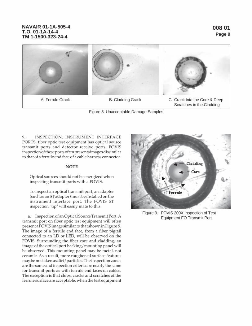
008 01Page 9
NAVAIR 01-1A-505-4T.O. 01-1A-14-4TM 1-1500-323-24-4
A. Ferrule Crack B. Cladding Crack C. Crack Into the Core & DeepScratches in the Cladding
Figure 8. Unacceptable Damage Samples
9. INSPECTION, INSTRUMENT INTERFACEPORTS. fiber optic test equipment has optical sourcetransmit ports and detector receive ports. FOVISinspection of these ports often presents images dissimilarto that of a ferrule end face of a cable harness connector.
NOTE
Optical sources should not be energized wheninspecting transmit ports with a FOVIS.
To inspect an optical transmit port, an adapter(such as an ST adapter) must be installed on theinstrument interface port. The FOVIS STinspection "tip" will easily mate to this.
a. Inspection of an Optical Source Transmit Port. Atransmit port on fiber optic test equipment will oftenpresent a FOVIS image similar to that shown in Figure 9.The image of a ferrule end face, from a fiber pigtailconnected to an LD or LED, will be observed on theFOVIS. Surrounding the fiber core and cladding, animage of the optical port backing/mounting panel willbe observed. This mounting panel may be metal, notceramic. As a result, more roughened surface featuresmay be mistaken as dirt/particles. The inspection zonesare the same and inspection criteria are nearly the samefor transmit ports as with ferrule end faces on cables.The exception is that chips, cracks and scratches of theferrule surface are acceptable, when the test equipment
Figure 9. FOVIS 200X Inspection of TestEquipment FO Transmit Port

008 01Page 10
NAVAIR 01-1A-505-4T.O. 01-1A-14-4TM 1-1500-323-24-4
is used as ground support equipment. The damage andpollutant criteria for the critical zone (fiber core andcladding) are the same. Chips, cracks and scratches areunacceptable in the critical zone.
NOTE
To inspect an optical receiver port, the FOVISmust be focused until some distinguishablefeatures are observed on the photodetector orsurrounding surface.
To inspect an optical receiver port, an adapter(such as an ST adapter) must be installed on theinstrument interface port. The FOVIS STinspection “tip” will easily mate to this.
b. Inspection of an Optical Receive Port. A receiveport (typically a power meter) on fiber optic testequipment will present a FOVIS image similar to thatshown in Figure 10. There is a photodetector behind theoptical connection port on an optical power meter orthe port on an OLTS (optical loss test set). The image ofthis large photodetector will be displayed by the FOVIS.No image will be viewed of a ferrule end with a fiber inthe center. Surrounding the photodetector, some of theoptical port backing/mounting panel may be observed.
Figure 10.FOVIS 200X Inspection of TestEquipment Receive Port
Here the entire photodetector surface is thephotodetector critical zone. Chips, cracks and scratchesare unacceptable in this critical zone. This critical zoneshould be clean such that no pollutants are found, thatby themselves or cumulatively, would obstruct morethan 5% of the photodetector area (photodetector criticalzone).

008 02Page 1
NAVAIR 01-1A-505-4T.O. 01-1A-14-4TM 1-1500-323-24-4
Manual Cleaning Procedures
Reference Material
None
Alphabetical Index
Subject Page No.
Cleaning Techniques ........................................................................................................................... 4Cleaning with Compressed Gas ..................................................................................................... 8Cleaning with Swabs and/or Wipes ............................................................................................... 4Swab and Wipe Usage ................................................................................................................... 6
Introduction ......................................................................................................................................... 4
Record of Applicable Technical Directives
None
13 August 2004

008 02Page 2
NAVAIR 01-1A-505-4T.O. 01-1A-14-4TM 1-1500-323-24-4
metI noitpircseD ytitnauQ edoCegaC .oNgniyfitnedIrotraP 2/
TNEMPIUQETSET/NOITCEPSNIGNINAELC
NOITCEPSNIECAFDNEELURREF
711 esaco/wspiteborp/wtiKmetsySnoitcepsnIoediV)wolebsmetisedulcnitik( 1 7C8A3 A2-VAN-PBK
yalpsidrospiton,eborpnoitcepsnioediVX004/X002 1 7C8A3 1P-PBF
yalpsidoedivdlehdnah”5.2 1 7C8A3 1DH-PBF
sunimretnip4/40592MrofpiteborP 1 7C8A3 P2-LIM-TPBF
sunimrettekcos5/40592MrofpiteborP 1 7C8A3 S2-LIM-TPBF
elurref.aidmm5.2rofpiteborpdrochctaP 1 7C8A3 M52U-TPBF
elurref.aidmm52.1rofpiteborpdrochctaP 1 7C8A3 M21U-TPBF
retpadaTS-ot-TSurhtuv,piteborpretpadA 1 7C8A3 TS-TPBF
retpadaCS-ot-CSurhtuv,piteborpretpadA 1 7C8A3 CS-TPBF
retpadaCF-ot-CFurhtuv,piteborpretpadA 1 7C8A3 CF-TPBF
retpadaCL-ot-CLurhtuv,piteborpretpadA 1 7C8A3 CL-TPBF
retpadaeborprotcennoc99983M,piteborpretpadA 1 7C8A3 APC2-LIM-TPBF
1/
2/
tseTkniLlacitpO,tfarcriA,citpOrebiF,teStseT,2282167gniwarDAESVANrepdeificepsesohteraelbatsihtnismetI3.1.8.4RIAVANehthguorhtdevorppaeradnanidnuofeblliwsmetiesehtotsnoisiverynA.seirosseccA&tnempiuqE
.gniwardsihtrofssecorpecnatpecca.metiehtrofstnemeriuqerllufehtteemotdeifitnedineebevahtahtstcudorp'srerutcafunamroferadetsilsrebmuntraP
denimretedebotyitlibacilppA.tesehtgnittiftuorofstcudorptnelaviuqeecudorpotemoclewerasrerutcafunamrehtO.ssecorpmetsysylppuselbacilppaehthguorht
Support Equipment Required 1/

008 02Page 3
NAVAIR 01-1A-505-4T.O. 01-1A-14-4TM 1-1500-323-24-4
Materials Required 1/
metI noitpircseD ytitnauQ edoCegaC .oNgniyfitnedIrotraP 2/
)SROTCENNOCROF(SEILPPUSGNINAELCDRADNATS
101D )gnitsudcipocsorcim(sagdeifeuqildennaC4419643100586:NSN9117894100386:NSN
A/N 76212 0221SE
6FZ90 7053
201D etihw,gninaelchtolc,sepiW1976123100297:NSN
A/N 49912 404XT
00745 001-1532hceT
301D )lohoclarof(foorpkael,.zo4tnevlos,resnepsiD7635934105218:NSN
A/N 29033 4173
suordyhnaerup%99,lyporposI,lohoclA3156502005056:NSN
A/N 75716 61-3421-59300CDN
401D mm52.1,bawsgninaelC 05 00745 05-6132
04 12NL0 0090-21-SPCC
501D mm5.2,bawsgninaelC 05 00745 05-7132
04 12NL0 0090-52-SPCC
A/N 9741K 00400141
601D )05(stekcapdetarutas-erp,lohoclalyporposI,sepiW9566414100186NSN
A/N
701D leeregdirtrac,sepiW 1 4BEW1 7226
191D hcuop)DOF(sirbeDtcejbOngieroF 6 6CR80 0203-0040
SEILPPUSGNINAELCETANRETLA/LATNEMELPPUS
202D )701Dmetirof(epatgninaelctnemecalpeR A/N 4BEW1 2326
302D eerfCFC,renaelctcatnoclacirtcelE A/N 42766 61130
1/
2/
tseTkniLlacitpO,tfarcriA,citpOrebiF,teStseT,2282167gniwarDAESVANrepdeificepsesohteraelbatsihtnismetI3.1.8.4RIAVANehthguorhtdevorppaeradnanidnuofeblliwsmetiesehtotsnoisiverynA.seirosseccA&tnempiuqE
.gniwardsihtrofssecorpecnatpecca.metiehtrofstnemeriuqerllufehtteemotdeifitnedineebevahtahtstcudorp'srerutcafunamroferadetsilsrebmuntraP
denimretedebotyitlibacilppA.tesehtgnittiftuorofstcudorptnelaviuqeecudorpotemoclewerasrerutcafunamrehtO.ssecorpmetsysylppuselbacilppaehthguorht

008 02Page 4
NAVAIR 01-1A-505-4T.O. 01-1A-14-4TM 1-1500-323-24-4
1. INTRODUCTION.
2. This work package is for manual cleaning theferrule end face of a fiber optic connector or the ferruleend face of each terminus in a fiber optic, multipletermini connector. The manual techniques listed usehand cleaning procedures without any "powered"cleaning devices. The criteria defining a clean conditionwith respect to ferrule end faces are covered inWP 008 01.
3. CLEANING TECHNIQUES. A swab/wipecleaning technique and a compressed gas cleaningtechnique are covered below. In addition, guidance onthe usage of swabs and wipes is covered.
CAUTION
Inspect, clean (if needed) and re-inspect aftercleaning a connector/terminus ferrule andmating instrument adapters/interfacesimmediately before each mating to ensureaccurate and reproducible results. Perform theinspection and cleaning per this work package,WP 008 02.
NOTE
The criteria defining a clean condition withrespect to ferrule end faces are covered inWP 008 01. The number one cause for anincreased optical loss, after an insufficientlytight connection, is dirt and film deposits. Nosingle cleaning method has been found to datethat will guarantee a clean end face on theferrule. Magnified visual inspection togetherwith cleaning is important, when practical.Visual inspection is done using a FOVIS.Recommended cleaning supplies are listed inWP 008 02.
Inspection and cleaning of ferrule end faces onreplacement WRA, LRM or other avionics unitsshould be done prior to carrying replacementunits out to the flight deck or flight line. This ishighly important when conditions (wind, rain,etc.) on the flight deck or flight line may prohibitperformance of inspection and cleaning.
Always cover connectors (with ESD or dustcaps) immediately after unmating. Never usetape to cover connectors with fiber optic terminiin them.
Internal surfaces (other than ferrule end faces)of MIL-DTL-38999 type connectors may becleaned with wipes to remove excessparticulate/debris during interval maintenanceor general servicing.
a. Cleaning with Swabs and/or Wipes. This is thepreferred technique for cleaning end faces. Inspectionbefore and after cleaning is a requirement of thistechnique (unless superceded by the platformmaintenance manual). Cleaning an end face is not riskfree. Cleaning materials (such as swabs and wipes) caneasily become contaminated with particulate.Contaminated cleaning materials used on a clean endface may leave it spotted. Therefore, inspection mustalways determine when cleaning is required andinspection must always verify the result of a cleaningevent. Inspection before and after cleaning also providesefficient use of consumables. The flow chart in Figure 1summarizes the steps of this technique. The techniqueconsists of the following steps:
(1) Step 1. Inspect Ferrule End Face.
(a) If it is clean, the procedure is done. Ifnot proceed to Step (2).
(2) Step 2. Clean Ferrule End Face.
(a) If small particles and/or small liquidspots were observed: Clean with a dry swab or wipe. Goto Step (3).
NOTE
To dampen a fiber optic swab for cleaning,approved alcohol presaturated wipes shouldbe used to transfer alcohol to the swab. Thisavoids saturating the swab and "flooding" theend face.
Alcohol on and end face will leave a film orresidue if it is left to evaporate. After cleaningwith alcohol , a dry swab/wipe must be used todry the alcohol .
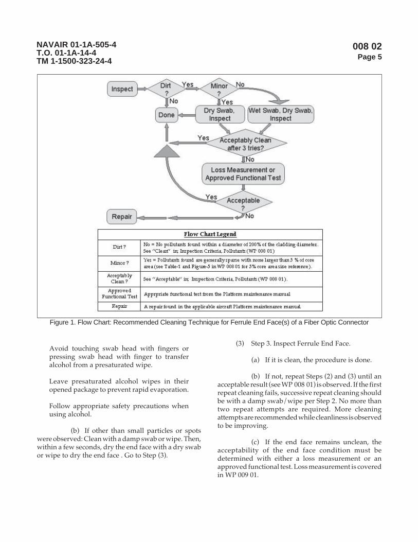
008 02Page 5
NAVAIR 01-1A-505-4T.O. 01-1A-14-4TM 1-1500-323-24-4
Avoid touching swab head with fingers orpressing swab head with finger to transferalcohol from a presaturated wipe.
Leave presaturated alcohol wipes in theiropened package to prevent rapid evaporation.
Follow appropriate safety precautions whenusing alcohol.
(b) If other than small particles or spotswere observed: Clean with a damp swab or wipe. Then,within a few seconds, dry the end face with a dry swabor wipe to dry the end face . Go to Step (3).
(3) Step 3. Inspect Ferrule End Face.
(a) If it is clean, the procedure is done.
(b) If not, repeat Steps (2) and (3) until anacceptable result (see WP 008 01) is observed. If the firstrepeat cleaning fails, successive repeat cleaning shouldbe with a damp swab/wipe per Step 2. No more thantwo repeat attempts are required. More cleaningattempts are recommended while cleanliness is observedto be improving.
(c) If the end face remains unclean, theacceptability of the end face condition must bedetermined with either a loss measurement or anapproved functional test. Loss measurement is coveredin WP 009 01.
Figure 1. Flow Chart: Recommended Cleaning Technique for Ferrule End Face(s) of a Fiber Optic Connector

008 02Page 6
NAVAIR 01-1A-505-4T.O. 01-1A-14-4TM 1-1500-323-24-4
b. Swab and Wipe Usage. These handling practiceshelp to avoid damaging end faces, avoid crosscontamination of swabs and wipes, and generallyimprove cleaning efficiency.
(1) Swab Usage. Fiber optic swabs are of a low-lint design. Care must be exercised to avoidcontaminating them with any particulate or fluids beforethey are used. Once taken out of a storage package thecleaning tip end must not contact anything but theferrule end face to be cleaned.
(a) Life of Swabs (Single use versusmultiple usage). The job of a swab is to accumulate dirt.Swabs have very limited reusability. One swab percleaning event is recommended.
NOTE
After using a swab, deform it by bending. This canhelp to avoid the mistaken use of a dirty swab.
1 Recommended Practice. Use oneswab per contact with the ferrule, then discard. This isindustry practice. This practice ensures maximumparticle removal capability of the swab.
2 Economy Practice. Use the sameswab until retention of particles on the ferrule is observedduring inspection after the last cleaning.
(b) Applied Pressure. Applied pressureshould always be light. Light pressure minimizes therisk of scratching an end face by dragging a hardparticle across the end face.
NOTE
This technique addresses alignment sleeves insingle terminus adapters (such as ST-to-STadapters), multiple termini connector adapters(MIL-DTL-38999 adapters) and loose alignmentsleeves of disassembled socket termini.
The job of a swab is to accumulate dirt. Swabshave very limited reusability. One swab percleaning event is recommended.
Avoid pulling swab back through alignmentsleeve with the opposite rotation.
(c) Cleaning Alignment Sleeves inConnector Adapters. Alignment sleeves are found invarious single terminus adapters (such as ST-to-STadapters) and multiple termini connector adapters (MIL-DTL-38999 adapters).
1 Technique: Use a swab to cleanalignment sleeves. Insert swab, rotate 1 revolution whilepassing through, rotate 1 revolution (same direction)while extracting (see Table 1).
NOTE
The job of a swab is to accumulate dirt. Swabshave very limited reusability. One swab percleaning event is recommended.
(d) Cleaning Pin Termini. Use 2.5 mm fiberoptic swabs to clean exposed ferrules of pin termini.
1 Recommended Technique: Lightlypress the swab tip against the ferrule end face. Thenwipe with one straight-line movement across the ferruleend face. Do not repeatedly wipe with the same sectionof the swab. Dirt that has been picked up by the swabcan be transferred back.
Table 1. Swab Size Recommendations forCleaning Applications
piTbawS)mm(eziS
gninaelCnoitacilppA
52.1 niselurrefderugifnoctekcoS•srotcennoc99983-LTD-LIM
99983-LTD-LIMniseveelstnemngilA•.sretpadarotcennocdnasrotcennoc
rotcennocniselurrefdesseceR•elamefrodaehklub,sretpada
srotcennocCLderugifnoc
5.2 niselurrefderugifnocniP•srotcennoc99983-LTD-LIM
rotcennocynafoselurrefdesopxE•).cte,CL,CS,CF,TSsahcus(
tnemngiladnaselurrefdesseceR•daehklub,sretpadarotcennocniseveels
CSdnaCF,TSderugifnocelamefrosrotcennoc

008 02Page 7
NAVAIR 01-1A-505-4T.O. 01-1A-14-4TM 1-1500-323-24-4
2 Alternate Techniques:
a Lightly press swab tip againstthe ferrule end face one to two times.
b Lightly press swab tip againstthe ferule end face and rotate 1/2 to 1 revolution.
NOTE
The job of a swab is to accumulate dirt. Swabshave very limited reusability. One swab percleaning event is recommended.
Alignment sleeve surfaces of recessed ferrulesin socket configured termini, will accumulatepollutants that need cleaning.
(e) Cleaning Socket Termini. Use 1.25mmfiber optic swabs to clean recessed ferrules andalignment sleeves of socket termini.
1 Recommended Technique: Insertswab. Rotate swab 1 revolution as swab approaches theferrule end face. Once contact is made press lightly androtate 1/2 to 1 revolution. Lift swab off the ferrule andremove in a straight outward movement.
2 Alternate Techniques: Two alternatetechniques are presented.
a Insert and rotate the swab1 revolution down the alignment sleeve. Once contactis made with the ferrule, press, straight down, againstthe ferrule a couple of times (lifting swab slightly off theferrule after each press). Lift swab off the ferrule andremove in a straight outward movement.
b Insert and push straight downuntil light contact is made with the ferrule. Rotate theswab for three revolutions (3 x 360°), then pull outstraight.
(2) Wipe Usage. Wipes are only effective incleaning exposed ferrules of single ferrule connectors(such as found on CMQJs and fiber optic test equipment).Fiber optic wipes are of a low-lint design. Care must beexercised to avoid contaminating them with particulateor fluids before they are used. Fiber optic wipes areavailable in several forms: presaturated with alcohol,
cartridge containers with a replaceable reel of dry wipecloth, and as dry loose cloth.
NOTE
Wipes should never be used to clean multipleferrule connectors. Cross contamination amongferrules is uncontrollable when using a wipeon a multiple ferrule connector.
When using wipes presaturated with alcohol,care must be taken to use the wipe before thealcohol evaporates and leaves the wipe dry.
Leave presaturated alcohol wipes in theiropened package to prevent rapid evaporation.
Alcohol on and end face will leave a film orresidue if it is left to evaporate. After cleaningwith alcohol, a dry wipe must be used to drythe alcohol.
When using loose cloth fiber optic wipes, useseveral (at least four) wipes in a stack to avoidskin contaminants leaching through from handsto the fiber optic ferrule being cleaned.
When using loose cloth fiber optic wipes, andcleaning is finished, remove and discard bottomwipe/cloth before placing remainder of wipes/cloths back into their storage package. Thisavoids skin contaminants leaching throughfrom the handled cloth to rest of the stack.
(a) Life of Wipes The job of a wipe is toaccumulate dirt. Reuse of wipes requires extreme careto avoid reusing a previously used section of a wipecloth.
1 Recommended Practice. Use oneclean section of cloth per contact with the ferrule.
(b) Applied Pressure. Applied pressureshould always be light. Light pressure minimizes therisk of scratching an end face by dragging a hardparticle across the end face.
(c) Cleaning Exposed Ferrules. Move ferruleacross the wipe in a gentle 1/2 to 1 inch linear motion. Usea different area of the wipe for each cleaning event.

008 02Page 8
NAVAIR 01-1A-505-4T.O. 01-1A-14-4TM 1-1500-323-24-4
c. Cleaning with Compressed Gas. Cleaning withcompressed (liquefied) gas is not recommended on ornear aircraft. This technique is recommended forcleaning connector adapters and single ferruleconnectors in relatively clean environments. Cleaningwith compressed gas is also recommended for cleaningWRA, LRU or other avionics units before installation(provided that ESD or dust caps are covering the fiberoptic connectors). This technique may only be used onaircraft if the Platform maintenance manual does notrestrict its use. However, if the Platform maintenancemanual does not restrict its use, it is still notrecommended for the reasons noted below. Inspectionbefore and after cleaning is a requirement of thistechnique when used on termini (unless superceded byPlatform maintenance manual). Cleaning an end face isnot risk free. Ambient particulate and compressed gaspropellant can leave the target termini and neighboringtermini spotted. Therefore, inspection must alwaysdetermine when termini cleaning is required andinspection must always verify the result of a terminicleaning event. Inspection of termini before and aftercleaning also provides efficient use of consumables. Apractice to follow if compressed gas is authorized aspart of a cleaning procedure follows:
NOTE
Canned compressed gas or canned liquefiedgas intended for use in microscopic dustingapplications is often incorrectly referred to ascanned air. These items may contain haloge-nated hydrocarbons or 1,1,1,2 tetrafluoroethaneand usually contain no air.
Use of compressed gas is not recommended toclean ferrule end faces on or near aircraft.Ambient conditions (including particulate andaerosols) on and near aircraft are not compatiblewith efficient and effective cleaning usingcompressed gas.
Use of compressed gas is not recommended toclean ferrule end faces of multiple terminiconnectors. Transfer of ambient pollutants tothe target and neighboring termini is a risk. Thepost cleaning inspection requirement appliesto every end face of a multiple termini connector,when one end face is cleaned with compressedgas.
Use of compressed gas to clean ferrule endfaces requires extreme care to avoid expellingliquid propellant. The can must be held upright.
Use of compressed gas for any cleaning requiresthe exit nozzle or extension tube is clean andfree of pollutants that could transfer to the itembeing cleaned.
Use only the compressed gas type designatedfor this application. Generic duster cans maynot be adequately filtered to remove particulatethat can deposit on ferrule end faces.
(1) Cleaning Alignment Sleeves in ConnectorAdapters. Connector adapters and connector ports havehollow alignment sleeves that accumulate pollutants.To clean these alignment sleeves or loose alignmentsleeves, blow directly through the alignment sleeve.Hold the gas can upright. Hold the gas tube tip from thecan of compressed gas at least four inches away fromthe sleeve. This orientation is done to minimize liquidpropellant contact with the sleeve. Blow a steady streamof gas (not short bursts) through the alignment sleeve.
(2) Cleaning Pin Termini. To clean exposedferrules of pin termini, blow across (parallel to) theferrule end face. Hold the gas can upright. Hold the gastube tip from the can of compressed gas at least fourinches away from the end face. This orientation is doneto minimize liquid propellant contact with the end face.Blow a steady stream of gas (not short bursts) across theferrule end face.
(3) Cleaning Socket Termini. To clean recessedferrules of socket termini, blow nearly directly at (almostperpendicular to) the ferrule end face. Hold the gas canupright. Hold the gas tube tip from the can of compressedgas at least four inches away from the end face. Thisorientation is done to minimize liquid propellant contactwith the end face. Blow a steady stream of gas (not shortbursts) at the ferrule end face.

009 00Page 1
NAVAIR 01-1A-505-4T.O. 01-1A-14-4TM 1-1500-323-24-4
Testing
Reference Material
None
Alphabetical Index
None
LIST OF SUBORDINATE WORK PACKAGES
SUBORDINATESUBJECT WORK PACKAGE DATEOptical Loss Measurement, One Jumper Method 009 01 13 August 2004Optical Loss Measurement, Two Jumper Method 009 02 13 August 2004CMQJ Field Check Method (ST-to-ST CMQJ) 009 03 13 August 2004Optical Return Loss Measurement Method 009 04 13 August 2004Fault Location Isolation Method Using OTDR 009 05 13 August 2004Fault Location Isolation Method Using Fault Finder 009 06 13 August 2004Test Probe CMQJ Insertion and Removal 009 07 13 August 2004
Record of Applicable Technical Directives
None
13 August 2004
1. INTRODUCTION.
2. This work package (WP) is divided intosubordinate work packages for different types of testand troubleshooting procedures. Work packages are
provided for acceptance and verification tests (for opticalloss and optical return loss, quality conformance (CMQJfield check), and troubleshooting (fault isolation usingboth an OTDR and a fault finder).
Page 1/2 (Blank)

009 00Page 2
NAVAIR 01-1A-505-4T.O. 01-1A-14-4TM 1-1500-323-24-4
THIS PAGE LEFT INTENTIONALLY BLANK

009 01Page 1
NAVAIR 01-1A-505-4T.O. 01-1A-14-4TM 1-1500-323-24-4
Optical Loss Measurement, Two Jumper Method
Reference Material
Definitions ............................................................................................................................. WP 003 01Safety .................................................................................................................................... WP 004 01Handling ................................................................................................................................ WP 006 01Inspection .............................................................................................................................. WP 008 01Manual Cleaning Procedures ................................................................................................. WP 008 02
Alphabetical Index
Subject Page No.
Introduction .......................................................................................................................................... 5Optical Loss Measurement, Two Jumper Method. ................................................................................ 5
Determinations for Acceptance of Optical Loss ............................................................................. 12First power measurement (P
1) ........................................................................................................ 6
Safety Summary ............................................................................................................................ 6Second Power Measurement (P
2) & CMQJ Field Check (P
2-P
1) .................................................... 9
Test Measurement (P3) & Cable Harness Measurement (P
3-P
2) ...................................................... 10
Record of Applicable Technical Directives
None
13 August 2004
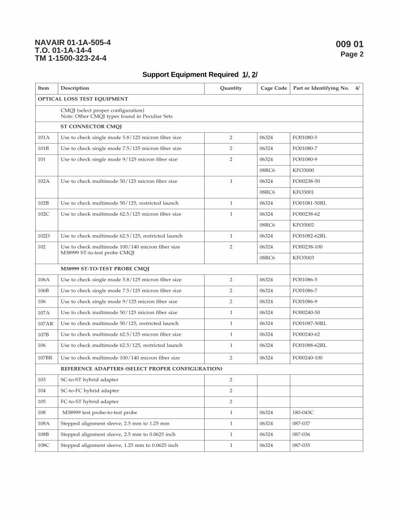
009 01Page 2
NAVAIR 01-1A-505-4T.O. 01-1A-14-4TM 1-1500-323-24-4
metI noitpircseD ytitnauQ edoCegaC .oNgniyfitnedIrotraP 4/
TNEMPIUQETSETSSOLLACITPO
)noitarugifnocreporptceles(JQMCsteSrailucePnidnuofsepytJQMCrehtO:etoN
JQMCROTCENNOCTS
A101 ezisrebifnorcim521/8.5edomelgniskcehcotesU 2 42360 5-08010OF
B101 ezisrebifnorcim521/5.7edomelgniskcehcotesU 2 42360 7-08010OF
101 ezisrebifnorcim521/9edomelgniskcehcotesU 2 42360 9-08010OF
6CR80 0003OFK
A201 ezisrebifnorcim521/05edomitlumkcehcotesU 1 42360 05-83200OF
6CR80 1003OFK
B201 hcnualdetcirtser,521/05edomitlumkcehcotesU 1 42360 LR05-18010OF
C201 ezisrebifnorcim521/5.26edomitlumkcehcotesU 1 42360 26-83200OF
6CR80 2003OFK
D201 hcnualdetcirtser,521/5.26edomitlumkcehcotesU 1 42360 LR26-28010OF
201 ezisrebifnorcim041/001edomitlumkcehcotesUJQMCeborptset-ot-TS99983M
2 42360 001-83200OF
6CR80 3003OFK
JQMCEBORPTSET-OT-TS99983M
A601 ezisrebifnorcim521/8.5edomelgniskcehcotesU 2 42360 5-68010OF
B601 ezisrebifnorcim521/5.7edomelgniskcehcotesU 2 42360 7-68010OF
601 ezisrebifnorcim521/9edomelgniskcehcotesU 2 42360 9-68010OF
A701 ezisrebifnorcim521/05edomitlumkcehcotesU 1 42360 05-04200OF
RA701 hcnualdetcirtser,521/05edomitlumkcehcotesU 1 42360 LR05-78010OF
B701 ezisrebifnorcim521/5.26edomitlumkcehcotesU 1 42360 26-04200OF
601 hcnualdetcirtser,521/5.26edomitlumkcehcotesU 1 42360 LR26-88010OF
RB701 ezisrebifnorcim041/001edomitlumkcehcotesU 2 42360 001-04200OF
)NOITARUGIFNOCREPORPTCELES(SRETPADAECNEREFER
301 retpadadirbyhTS-ot-CS 2
401 retpadadirbyhCF-ot-CS 2
501 retpadadirbyhTS-ot-CF 2
801 eborptset-ot-eborptset99983M 1 42360 C340-081
A801 mm52.1otmm5.2,eveelstnemngiladeppetS 1 42360 730-780
B801 hcni5260.0otmm5.2,eveelstnemngiladeppetS 1 42360 630-780
C801 hcni5260.0otmm52.1,eveelstnemngiladeppetS 1 42360 530-780
Support Equipment Required 1/, 2/

009 01Page 3
NAVAIR 01-1A-505-4T.O. 01-1A-14-4TM 1-1500-323-24-4
Support Equipment Required 1/, 2/ (cont.)
metI noitpircseD ytitnauQ edoCegaC .oNgniyfitnedIrotraP 4/
(TNEMPIUQETSETSSOLLACITPO tnoc ).
SEIROSSECCA&SECRUOSLACITPO
901 )lliflluf,mn0031&mn058,DEL(ecruoslacitpO 1 35YX0 001SA-A252
A901 )mn0551&0131,DL(ecruoslacitpO 1
011 )yekworran(retpadaCF 1
111 retpadaTS 1
SEIROSSECCA&RETEMREWOPLACITPO
211 )sAaGnImm1,mBd06-ot3+(retemrewoplacitpO 1
311 )COS(ecafretnirotcennoCnO-panS,retpadaCF 1
411 COS,retpadaTS 1
511 COS,99983M,retpadaeborptseT 1
SRETPADAEBORPROTCENNOC 3/
SRETPADAEBORPROTCENNOC99983MNOMMOC
811 P2-P11-3M-1282167.ongwd,P2-P11-3M 1 42360 P2-11-60FN440-081
911 N-S2-R11-3M-1282167.ongwd,N-S2-R11-3M 1 42360 S2-11-70FN440-081
021 P4-P31-3M-1282167.ongwd,P4-P31-3M 1 42360 P4-31-60FN440-081
121 N-S4-R31-3M-1282167.ongwd,N-S4-R31-3M 1 42360 S4-31-70FN440-081
221 P5-P51-3M-1282167.ongwd,P5-P51-3M 1 42360 P5-51-60FN440-081
321 N-S5-R51-3M-1282167.ongwd,N-S5-R51-3M 1 42360 S5-51-70FN440-081
421 P8-P71-3M-1282167.ongwd,P8-P71-3M 1 42360 P8-71-60FN440-081
521 N-S8-R71-3M-1282167.ongwd,N-S8-R71-3M 1 42360 S8-71-70FN440-081
621 P11-P91-3M-1282167.ongwd,P11-P91-3M 1 42360 P11-91-60FN370-081
721 N-S11-R91-3M-1282167.ongwd,N-S11-R91-3M 1 42360 S11-91-70FN370-081
821 P73-P52-3M-1282167.ongwd,P73-P52-3M.onmetisihthtiwdedulcnierasretpadaowT:etoN
1 42360 PA73-52-60FN370-081PB73-52-60FN370-081
921 N-S73-R52-3M-1282167.ongwd,N-S73-R52-3M.onmetisihthtiwdedulcnierasretpadaowT:etoN
1 42360 SA73-52-70FN370-081SA73-52-70FN370-081
SRETPADAEBORPROTCENNOC99983MCIFICEPSTFARCRIA/MARGORPTNERRUC
702 A-S8-P71-3M-1282167.ongwd,A-S8-P71-3M 1 42360 S8-71-60FN440-081
802 A-P8-R71-3M-1282167.ongwd,A-P8-R71-3M 1 42360 AP8-71-70FN440-081
902 P61-P12-3M-1282167.ongwd,P61-P12-3M 1 42360 P61-12-60FN270-081
012 P45-P32-3M-1282167.ongwd,P45-P32-3M 1 42360 P45-32-60FN370-081

009 01Page 4
NAVAIR 01-1A-505-4T.O. 01-1A-14-4TM 1-1500-323-24-4
Support Equipment Required 1/, 2/ (cont.)
metI noitpircseD ytitnauQ edoCegaC .oNgniyfitnedIrotraP 4/
SRETPADAEBORPROTCENNOC 3/ ).tnoc(
SRETPADAEBORPROTCENNOC99983MCIFICEPSTFARCRIA/MARGORPTNERRUC ).tnoc(
112 N-S45-R32-3M-1282167.ongwd,N-S45-R32-3M 1 42360 S45-32-70FN370-081
212 N-P45-R32-3M-1282167.ongwd,N-P45-R32-3M 1 42360 P45-32-00FN370-081
312 C-S92-R52-3M-1282167.ongwd,C-S92-R52-3M 1 42360 CS92-52-70FN440-081
412 P34-P52-3M-1282167.ongwd,P34-P52-3M 1 42360 P34-52-60FN440-081
512 N-S34-R52-3M-1282167.ongwd,N-S34-R52-3M 1 42360 S34-52-70FN440-081
)EPYTEMASEHTFOSROTCENNOCELURREFELGNIS2ETAM(,ELURREFELGNIS,SRETPADA
10ATS dezidegguR,STOC,edomelgnis,retpadaTS-ot-TS 1
20ATS ,STOC,norcim521,edomitlum,retpadaTS-ot-TSdezideggur
1
10ACS xelpmis,STOC,edomelgnis,retpadaCS-ot-CS 1
20ACS xelpmis,STOC,norcim521,edomitlum,retpadaCS-ot-CS 1
10ACL xelpud,STOC,edomelgnis,retpadaCL-ot-CL 1
20ACL xelpud,STOC,edomitlum,retpadaCL-ot-CL 1
SLOOTLATNEMELPPUS
SROTCENNOC99983MNIINIMRETEVOMER&TRESNIOTSLOOT
141 )citsalp(5/&4/40592Mroflootnoitcartxe&noitresnI 3 94318 30-41/96918M
241 )latem(5/&4/40592MlootnoitresnI 1 94318 702-8/96918M
341 )latem(5/&4/40592MlootnoitcartxE 1 94318 802-8/96918M
ECNEREFERYBDEDULCNITNEMPIUQETROPPUS
)20800PW(gninaelClaunaMdna)10800PW(noitcepsnIroftnempiuqEtroppuSeeS
1/ tseTkniLlacitpO,tfarcriA,citpOrebiF,teStseT,2282167gniwarDAESVANrepdeificepsesohteraelbatsihtnismetIrepdeificepsesohteraelbatsihtnisretpadaecnereferdnasretpadaeborprotcennoc,JQMCehT.seirosseccA&tnempiuqEotsnoisiverynA.citpOrebiF,tnempiuqEtsetroF,)JQMC(srepmuJytilauQtnemerusaeMSTOC,1282167gniwarDAESVAN
.sgniwardesehtrofssecorpecnatpecca3.1.8.4RIAVANehthguorhtdevorppaeradnanidnuofeblliwsmetieseht
2/ noitcepsnigninaelcdnemmoceR.emulovsihtnigninaelCrednudetsileragninaelcrotcennocroftnempiuqenoitcepsnI.spiteborpnoitcepsnielbacilppahtiw)SIVOF(metsySnoitcepsnIoediVcitpOrebiFasedulcnitnempiuqe
3/ :)rotcennoc99983-LTD-LIMehthtiwesurof(snoitangisedretpadaeborprotcennoC:swollofsaera)N-S2-R11-3Msahcus(noitpircsednisnoitangiseD
piteborprotcennocehthtiwelbitapmocrotcennocinimretelpitlumfoepyT=3M)elcatpecer=R,gulp=P(epytydobdnaezisllehsretpadaeborprotcennoC=R11)tekcos=S,nip=P(ytivactresnirofepytinimretdnaseitivactresniforebmuN=S2
epytgulP.ylnosretpadaeborpepytelcatpecerrof,elbacilppaeraFhguorhtAosla,lamron=N(noitisopgniyek=N.)selcatpecer99983Mdeyekynatifnacsretpadaeborprotcennoc
4/ .metiehtrofstnemeriuqerllufehtteemotdeifitnedineebevahtahtstcudorp'srerutcafunamroferadetsilsrebmuntraPdenimretedebotytilibacilppA.tesehtgnittiftuorofstcudorptnelaviuqeecudorpotemoclewerasrerutcafunamrehtO
.ssecorpylppuselbacilppaehthguorht
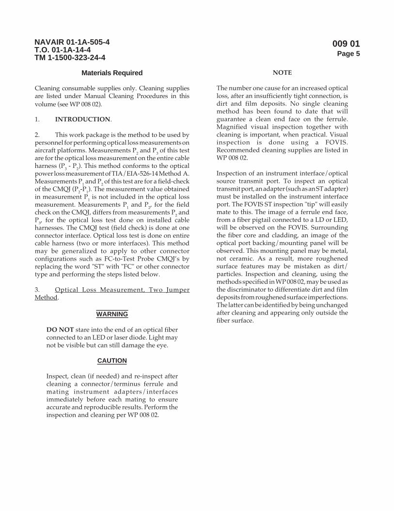
009 01Page 5
NAVAIR 01-1A-505-4T.O. 01-1A-14-4TM 1-1500-323-24-4
Materials Required
Cleaning consumable supplies only. Cleaning suppliesare listed under Manual Cleaning Procedures in thisvolume (see WP 008 02).
1. INTRODUCTION.
2. This work package is the method to be used bypersonnel for performing optical loss measurements onaircraft platforms. Measurements P2 and P3 of this testare for the optical loss measurement on the entire cableharness (P3 - P2). This method conforms to the opticalpower loss measurement of TIA/EIA-526-14 Method A.Measurements P1 and P2 of this test are for a field-checkof the CMQJ (P2-P1). The measurement value obtainedin measurement P1 is not included in the optical lossmeasurement. Measurements P1 and P2, for the fieldcheck on the CMQJ, differs from measurements P2 andP3, for the optical loss test done on installed cableharnesses. The CMQJ test (field check) is done at oneconnector interface. Optical loss test is done on entirecable harness (two or more interfaces). This methodmay be generalized to apply to other connectorconfigurations such as FC-to-Test Probe CMQJ’s byreplacing the word "ST" with "FC" or other connectortype and performing the steps listed below.
3. Optical Loss Measurement, Two JumperMethod.
WARNING
DO NOT stare into the end of an optical fiberconnected to an LED or laser diode. Light maynot be visible but can still damage the eye.
CAUTION
Inspect, clean (if needed) and re-inspect aftercleaning a connector/terminus ferrule andmating instrument adapters/interfacesimmediately before each mating to ensureaccurate and reproducible results. Perform theinspection and cleaning per WP 008 02.
NOTE
The number one cause for an increased opticalloss, after an insufficiently tight connection, isdirt and film deposits. No single cleaningmethod has been found to date that willguarantee a clean end face on the ferrule.Magnified visual inspection together withcleaning is important, when practical. Visualinspection is done using a FOVIS.Recommended cleaning supplies are listed inWP 008 02.
Inspection of an instrument interface/opticalsource transmit port. To inspect an opticaltransmit port, an adapter (such as an ST adapter)must be installed on the instrument interfaceport. The FOVIS ST inspection "tip" will easilymate to this. The image of a ferrule end face,from a fiber pigtail connected to a LD or LED,will be observed on the FOVIS. Surroundingthe fiber core and cladding, an image of theoptical port backing/mounting panel will beobserved. This mounting panel may be metal,not ceramic. As a result, more roughenedsurface features may be mistaken as dirt/particles. Inspection and cleaning, using themethods specified in WP 008 02, may be used asthe discriminator to differentiate dirt and filmdeposits from roughened surface imperfections.The latter can be identified by being unchangedafter cleaning and appearing only outside thefiber surface.

009 01Page 6
NAVAIR 01-1A-505-4T.O. 01-1A-14-4TM 1-1500-323-24-4
Inspection of an instrument interface/opticalreceiver port. To inspect an optical receiverport, an adapter (such as an ST adapter) mustbe installed on the instrument interface port.The FOVIS ST inspection "tip" will easily mateto this. There is a photodetector behind theoptical connection port on an optical powermeter or the Rx port on an OLTS (optical losstest set). The image of this large photodetectorwill be displayed by the FOVIS. No image willbe viewed of a ferrule end with a fiber in thecenter. Adjust the FOVIS focus until somedistinguishable features on the photodetectorsurface or the surrounding surface are observed.Dirt or film deposits on the photodetectorsurface may now be seen. Surrounding thephotodetector, some of the optical port backing/mounting panel may be observed. Thismounting panel may be metal, not ceramic. Asa result, a more roughened surface featuresmay be mistaken as dirt/particles. Inspectionand cleaning, using the methods specified inWP 008 02, may be used as the discriminator todifferentiate dirt and film deposits fromroughened surface imperfections. The lattercan be identified by being unchanged aftercleaning and appearing only outside thephotodetector surface.
During handling, all the cables shall beprotected from kinks, twists, crushing and sharpbends bends (see Handling PracticesWP 006 01).
Ensure the test equipment calibration is current.
CMQJs wear out. CMQJs must be maintainedby inspection and cleaning per WP 008 01 andWP 008 02. CMQJs must be replaced when theyperform poorly after proper inspection andcleaning per WP 008 01 and WP 008 02.
Connector adapters accumulate dirt. Connectoradapters must be maintained by inspectionand cleaning per WP 008 01 and WP 008 02.
Always cover connectors (with ESD or dustcaps) immediately after unmating. Never usetape to cover connectors with fiber optic terminiin them.
For measurements on aircraft, or wherever toolcontrol and FOD are a concern, the P1 (seeFigure 1) and P2 (see Figure 2) measurementsof this procedure can be done in a work centerafter access to the cable harness to test has beenaccomplished. Then the optical loss tools canbe left all connected as shown in Figure 2 (withoptical source and power meter energized) andtaken out to the cable harness to test. Inspectionand cleaning (WP 008 02) will still need to beperformed at the cable harness to test.
a. Safety Summary. The safety precautions inWP 004 01 shall be observed. The following safetyprecautions are restated for emphasis:
(1) Do not touch the ends of the fiber as theymay be razor sharp. Wash your hands before and afterhandling bare fiber.
(2) Do not stare into the end of a fiber untilverifying that the fiber is not connected to a laser lightsource or LED.
b. First power measurement (P1).
NOTE
Before making loss measurements, make surethat both the light source and the power meterhave been energized for at least 5 minutes tohave stable performance.
CMQJ(s) used must be compatible withapplicable requirements specified in Platformmaintenance manual for fiber size and ferruleend face polish. Only like polish types (PC/PCor NC/NC) should be mated together.Generally, if the fiber size in the cable harnessbeing tested is multimode 50/125 micron or62.5/125 micron, then ensure that CMQJ1 isthe one with the restricted launch condition(CMQJ that states usage is for launch end only).
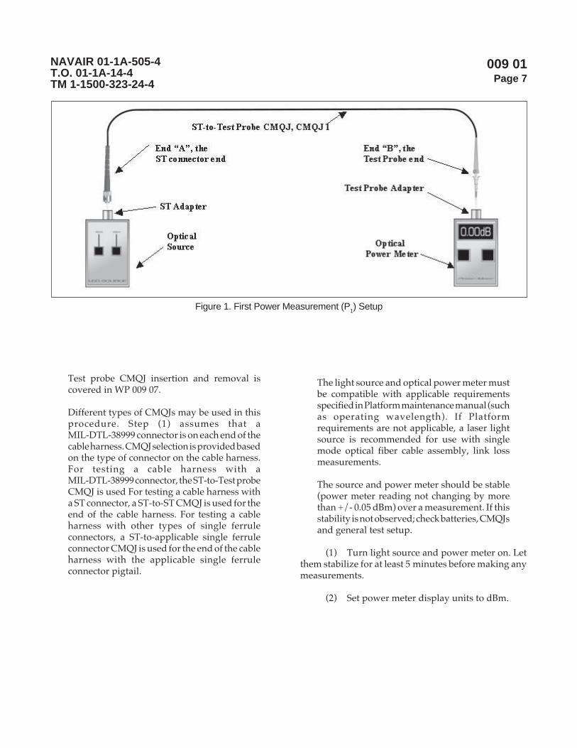
009 01Page 7
NAVAIR 01-1A-505-4T.O. 01-1A-14-4TM 1-1500-323-24-4
Test probe CMQJ insertion and removal iscovered in WP 009 07.
Different types of CMQJs may be used in thisprocedure. Step (1) assumes that aMIL-DTL-38999 connector is on each end of thecable harness. CMQJ selection is provided basedon the type of connector on the cable harness.For testing a cable harness with aMIL-DTL-38999 connector, the ST-to-Test probeCMQJ is used For testing a cable harness witha ST connector, a ST-to-ST CMQJ is used for theend of the cable harness. For testing a cableharness with other types of single ferruleconnectors, a ST-to-applicable single ferruleconnector CMQJ is used for the end of the cableharness with the applicable single ferruleconnector pigtail.
The light source and optical power meter mustbe compatible with applicable requirementsspecified in Platform maintenance manual (suchas operating wavelength). If Platformrequirements are not applicable, a laser lightsource is recommended for use with singlemode optical fiber cable assembly, link lossmeasurements.
The source and power meter should be stable(power meter reading not changing by morethan +/- 0.05 dBm) over a measurement. If thisstability is not observed; check batteries, CMQJsand general test setup.
(1) Turn light source and power meter on. Letthem stabilize for at least 5 minutes before making anymeasurements.
(2) Set power meter display units to dBm.
Figure 1. First Power Measurement (P1) Setup
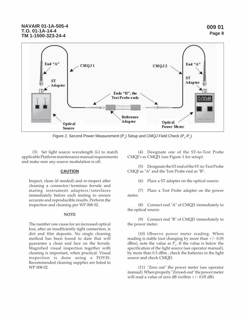
009 01Page 8
NAVAIR 01-1A-505-4T.O. 01-1A-14-4TM 1-1500-323-24-4
(3) Set light source wavelength (λ) to matchapplicable Platform maintenance manual requirementsand make sure any source modulation is off.
CAUTION
Inspect, clean (if needed) and re-inspect aftercleaning a connector/terminus ferrule andmating instrument adapters/interfacesimmediately before each mating to ensureaccurate and reproducible results. Perform theinspection and cleaning per WP 008 02.
NOTE
The number one cause for an increased opticalloss, after an insufficiently tight connection, isdirt and film deposits. No single cleaningmethod has been found to date that willguarantee a clean end face on the ferrule.Magnified visual inspection together withcleaning is important, when practical. Visualinspection is done using a FOVIS.Recommended cleaning supplies are listed inWP 008 02.
(4) Designate one of the ST-to-Test ProbeCMQJ’s as CMQJ1 (see Figure 1 for setup).
(5) Designate the ST end of the ST-to-Test ProbeCMQJ as "A" and the Test Probe end as "B".
(6) Place a ST adapter on the optical source.
(7) Place a Test Probe adapter on the powermeter.
(8) Connect end "A" of CMQJ1 immediately tothe optical source.
(9) Connect end "B" of CMQJ1 immediately tothe power meter.
(10) Observe power meter reading. Whenreading is stable (not changing by more than +/- 0.05dBm), note the value as P1. If the value is below thespecification of the light source (see operator manual),by more than 0.5 dBm , check the batteries in the lightsource and check CMQJ1.
(11) "Zero out" the power meter (see operatormanual). When properly "Zeroed-out" the power meterwill read a value of zero dB (within +/- 0.05 dB).
Figure 2. Second Power Measurement (P2) Setup and CMQJ Field Check (P
2-P
1)

009 01Page 9
NAVAIR 01-1A-505-4T.O. 01-1A-14-4TM 1-1500-323-24-4
c. Second Power Measurement (P2) and CMQJField Check (P2-P1).
NOTE
From this point forward, the power metershould be displaying values in units of dB andnot dBm.
The time delay between the measurement of P1and P2 shall be kept to a minimum (less than10 minutes) to prevent inaccuratemeasurements.
The value obtained for the second powermeasurement, P2 should be consistent from testto test. When making multiple cable harnessloss measurements, the P2 measurement can berepeated to verify the test setup is still valid.Generally, this P2 value should not change bymore than +/- 0.1 dB. Changes in the secondpower measurement greater than +/- 0.1 dBindicate either a dirty/defective CMQJ, adefective light source or an unstable powermeter. If changes in the second powermeasurement greater than +/- 0.1 dB occur,clean or replace the CMQJ and repeat the secondpower measurement.
The value obtained for the second powermeasurement (P2), should be less than the valueobtained for the first power measurement (P1).A value of the second power measurement (P2)greater than the value of the first powermeasurement (P1) indicates that either adefective or dirty CMQJ was used for the firstpower measurement (P1). If a value for thesecond power measurement (P2) greater thanthe value of the first power measurement (P1) isobtained, clean or replace CMQJ1 and repeatthe first power measurement (P1) and the secondpower measurement (P2).
Select the appropriate type of reference adapterbased on the two connectors/test probe CMQJsbeing connected. A test probe to test probeadapter is used when probe CMQJs are used. Ahybrid adapter is used when each CMQJ has adifferent connector type on the end. Forinstance, a test probe-to-1.25 mm adapter isused to connect the CMQJ ends together of atest probe to a single ferrule connector CMQJand one ST-to-test probe CMQJ.
Test probe CMQJ insertion and removal iscovered in WP 009 07.
(1) Designate another one of the ST-to-TestProbe CMQJ’s as CMQJ2 (see Figure 2 for setup).
(2) Designate the ST end of CMQJ2 as "A" andthe Test Probe end as "B".
CAUTION
Inspect, clean (if needed) and re-inspect aftercleaning a connector/terminus ferrule andmating instrument adapters/interfacesimmediately before each mating to ensureaccurate and reproducible results. Perform theinspection and cleaning per WP 008 02.
NOTE
The number one cause for an increased opticalloss, after an insufficiently tight connection, isdirt and film deposits. No single cleaningmethod has been found to date that willguarantee a clean end face on the ferrule.Magnified visual inspection together withcleaning is important, when practical. Visualinspection is done using a FOVIS.Recommended cleaning supplies are listed inWP 008 02.
(3) Detach end "B" of CMQJ1 from the powermeter (see Figure 1).
009 01Page 10
NAVAIR 01-1A-505-4T.O. 01-1A-14-4TM 1-1500-323-24-4
(4) Connect end "B" of CMQJ1 immediatelyinto one end of the reference adapter (see Figure 2).
(5) Remove the Test Probe adapter from thepower meter.
(6) Place a ST adapter on the power meter.
(7) Connect end "A" of CMQJ2 immediately tothe power meter.
(8) Connect end "B" of CMQJ2 immediatelyinto the other end of the reference adapter.
(9) Observe power meter reading. Whenreading is stable (not changing by more than +/- 0.05dB), note the value as P2. If this stability is not observed;check batteries, CMQJs and general test setup. P2 shouldbe a value within +0.1 to -0.5 dB range (if not checksetup for dirty/worn components).
(a) If P2 is within the +0.1 dB to -0.5 dBrange, continue (the P2 measurement is acceptable).
(b) If P2 is higher than +0.1 dB (e.g. +0.3dB), or If P2 is lower than -0.5 dB (e.g. -0.7 dB); thencheck setup for dirty/worn components and repeat P1and P2 measurements.
NOTE
The "zeroing-out" of the power meter aftermeasuring P2, is the difference between thetwo jumper and one jumper optical lossmeasurement methods.
(10) "Zero-out" the power meter. When properly"Zeroed-out" the power meter will read a value of zerodB (within +/- 0.05 dB).
NOTE
For measurements on aircraft, or wherever toolcontrol and FOD are a concern, the P1 (seeFigure 1) and P2 (see Figure 2) measurementsof this procedure can be done in a work centerafter access to the cable harness to test has beenaccomplished. Then the optical loss tools canbe left all connected as shown in Figure 2 (withoptical source and power meter energized) andtaken out to the cable harness to test. Inspectionand cleaning (WP 008 02) will still need to beperformed at the cable harness to test.
d. Test Measurement (P3) and Cable HarnessMeasurement (P3-P2).
CAUTION
Make sure that the proper connector probeadapter is used before attaching it to aMIL-DTL-38999 connector with fiber optictermini. Incorrect connector probe adapter mayresult in damage to the connector termini.
NOTE
Use the adapter that matches the connectors onthe cable harness to be tested. For cableharnesses under test terminated withMIL-DTL-38999 connectors, a connector probeadapter is used at each end to connect the testprobe end of the CMQJ to the MIL-DTL-38999connector. For cable harnesses under testterminated with ST connector pigtails at oneend, a ST-to-ST adapter is required to connectthe CMQJ to the ST connector pigtail end of thecable harness under test. For cable harnessesunder test terminated with SC or other singleferrule, fiber optic connectors on one end, ahybrid adapter is required to connect the CMQJto the pigtail end of the cable harness undertest.

009 01Page 11
NAVAIR 01-1A-505-4T.O. 01-1A-14-4TM 1-1500-323-24-4
The value obtained for the test measurement(P3), should be less than the value obtained forthe second power measurement (P2). A value ofthe test measurement power (P3) greater thanthe value of the second power measurement(P2) indicates that either a defective or dirtyCMQJ was used for the second powermeasurement (P2). If a value for the testmeasurement (P3) greater than the value of thesecond power measurement (P2) is obtained,clean or replace CMQJ1 and repeat the secondpower measurement (P2) and the testmeasurement (P3).
(1) Identify mating connector probe adaptersfor each end of the cable assembly/harness under test.
CAUTION
Inspect, clean (if needed) and re-inspect aftercleaning a connector/terminus ferrule andmating instrument adapters/interfacesimmediately before each mating to ensureaccurate and reproducible results. Perform theinspection and cleaning per WP 008 02.
NOTE
The number one cause for an increased opticalloss, after an insufficiently tight connection, isdirt and film deposits. No single cleaningmethod has been found to date that willguarantee a clean end face on the ferrule.Magnified visual inspection together withcleaning is important, when practical. Visualinspection is done using a FOVIS.Recommended cleaning supplies are listed inWP 008 02.
(2) Attach the connector probe adapters to theconnectors on each end of the cable harness under test(see Figure 3 for setup).
(3) Remove end "B" of CMQJ1 from the referenceadapter, and immediately place end "B" of CMQJ1 intothe proper position of the connector probe adapter.
(4) Remove end "B" of CMQJ2 from the referenceadapter, and immediately place end "B" of CMQJ2 intothe proper position of the second connector probeadapter.
Figure 3. Test Measurement (P3) and Cable Harness Optical Loss (P
3-P
2)

009 01Page 12
NAVAIR 01-1A-505-4T.O. 01-1A-14-4TM 1-1500-323-24-4
(7) For each connector/terminus position to betested, remove ends "B" of the two CMQJs then connectthem at the next position to be tested and redo step (6).
NOTE
Specific Platform requirements may not requirean additional loss measurement of multimodefiber in the opposite direction.
General practice is to also measure multimodefiber cables in the opposite direction. Generalpractice does not measure single-mode fibercables in the opposite direction. Swapping theconnections of the CMQJs connected to thecable harness under test, accomplishes thisdirectionality change (if the CMQJs are notdetached from the optical source and powermeters).
(8) Redo step (6) for each connector/terminusposition to be tested in the opposite direction.Inspecting/cleaning (WP 008 02) ends "B" of the twoCMQJs and the termini is required.
(9) Once testing is completed, secure testequipment. Install protective caps (dust covers) over allCMQJs, cable harness connectors and test equipmentports.
e. Determinations for Acceptance of Optical Loss.
(1) Optical loss is acceptable (in each directionfor multimode cable harness), if the measured opticalloss does not exceed the maximum acceptable opticalloss specified for the cable harness. Specific Platformrequirements may not require an additional lossmeasurement of multimode fiber in the oppositedirection. See Platform maintenance manual for theacceptable optical loss value(s). Optical loss values willbe specified in units of dB not dBm.
(2) If the measured optical loss (in eitherdirection for multimode cable harnesses) is above themaximum acceptable optical loss, then inspect and
(5) Observe power meter reading. When thereading is stable (not changing by more than +/- 0.05dB), note the value as P3. If this stability is not observed;check batteries, CMQJs and general test setup. Recordoptical power measurement P3.
NOTE
If optical loss is unacceptable, and the testsetup is valid, check connectors for propermating and inspect/clean(if necessary) allferrule end faces of the cable under test andCMQJs (see WP 008 02).
(6) Record optical loss. Generally, optical loss isacceptable if P3 is less than or equal to the specifiedmaximum acceptable optical loss for the cable harness.See specific Platform maintenance manual for themaximum acceptable optical loss value. Optical lossvalues will be specified in units of dB not dBm.
NOTE
When making multiple measurements, formultiple connector positions, inspect/clean(WP 008 02) ends "B" of the two CMQJs and thenext selected termini of the cable under test.
Verification of the test setup integrity may bedone after any measurement by rechecking theP2 measurement with the reference adapter.Changes in the second power measurementgreater than +/- 0.1 dB indicate either a dirty/defective CMQJ, a defective light source or anunstable power meter. If changes in the secondpower measurement greater than +/- 0.1 dBoccur, clean or replace the CMQJ and repeat theP1 and P2 measurements.
Verification of a CMQJ may be done after anymeasurement by following the CMQJ fieldcheck (WP 009 03), or by following the stepsfirst for the first power measurement (P1), thenfor the second power measurement (P2).

009 01Page 13
NAVAIR 01-1A-505-4T.O. 01-1A-14-4TM 1-1500-323-24-4
clean (WP 008 01, and WP 008 02) all the connectionsand retest. If the optical loss (in either direction formultimode cable harnesses) is still unacceptable, thenrepair/replacement of cable is needed. (See WP 012 01,and WP 013 01).
(3) If the maximum acceptable optical loss forthe cable harness is not specified, record the length ofthe cable from the vendor’s data or as measured. If thecable length is less than 10 meters, then a value of 0 maybe recorded. If the cable length is unknown a value of"0/unknown" may be recorded.
NOTE
The term BCA = Total cable harness optical lossin dB. Here, BCA = P3 (recorded previously).
The term MAL= Maximum Acceptable Loss.The term Aca = Maximum Attenuation of theCable. The term L = Length of the Cable. Theterm Ns = Number of Splices. The termLs = Loss of a splice (max.). The termNco = Number of connectors. The termLco = Loss of a connector (max.).
(a) Determine if the measurement isacceptable. Compare the measured optical loss (in eachdirection for multimode cable harness) to the maximumallowable optical loss. The maximum allowable opticalloss is calculated from the maximum specifiedcomponent optical loss values using the formula;
MAL = AcaL + NcoLco + NsLs
1 The cable harness is consideredacceptable if the measured optical loss (in each directionfor multimode cable assemblies) is equal to or less thanthe maximum acceptable optical loss.
2 If the measured optical loss (in eitherdirection for multimode cable harnesses) is above themaximum acceptable optical loss, then inspect andclean (WP 008 01, and WP 008 02) all the connectionsand retest. If the optical loss (in either direction formultimode cable harnesses) is still unacceptable, thenrepair/replacement of cable is needed. (See WP 012 01,and WP 013 01).
Page 13/14 (Blank)

009 01Page 14
NAVAIR 01-1A-505-4T.O. 01-1A-14-4TM 1-1500-323-24-4
THIS PAGE LEFT INTENTIONALLY BLANK

009 02Page 1
NAVAIR 01-1A-505-4T.O. 01-1A-14-4TM 1-1500-323-24-4
Optical Loss Measurement, One Jumper Method
Reference Material
Definitions ............................................................................................................................. WP 003 01Safety .................................................................................................................................... WP 004 01Handling ................................................................................................................................ WP 006 01Inspection .............................................................................................................................. WP 008 01Manual Cleaning Procedures ................................................................................................. WP 008 02
Alphabetical Index
Subject Page No.
Introduction .......................................................................................................................................... 5Optical Loss Measurement, One Jumper Method .................................................................................. 5
Determinations for Acceptance of Optical Loss ............................................................................. 12First Power Measurement (P
1) ....................................................................................................... 6
Safety Summary ............................................................................................................................ 6Second Power Measurement (P
2) & CMQJ Field Check (P
2-P
1) .................................................... 9
Test Measurement (P3) and Cable Harness Optical Loss (P
3-P
1) ..................................................... 10
Record of Applicable Technical Directives
None
13 August 2004
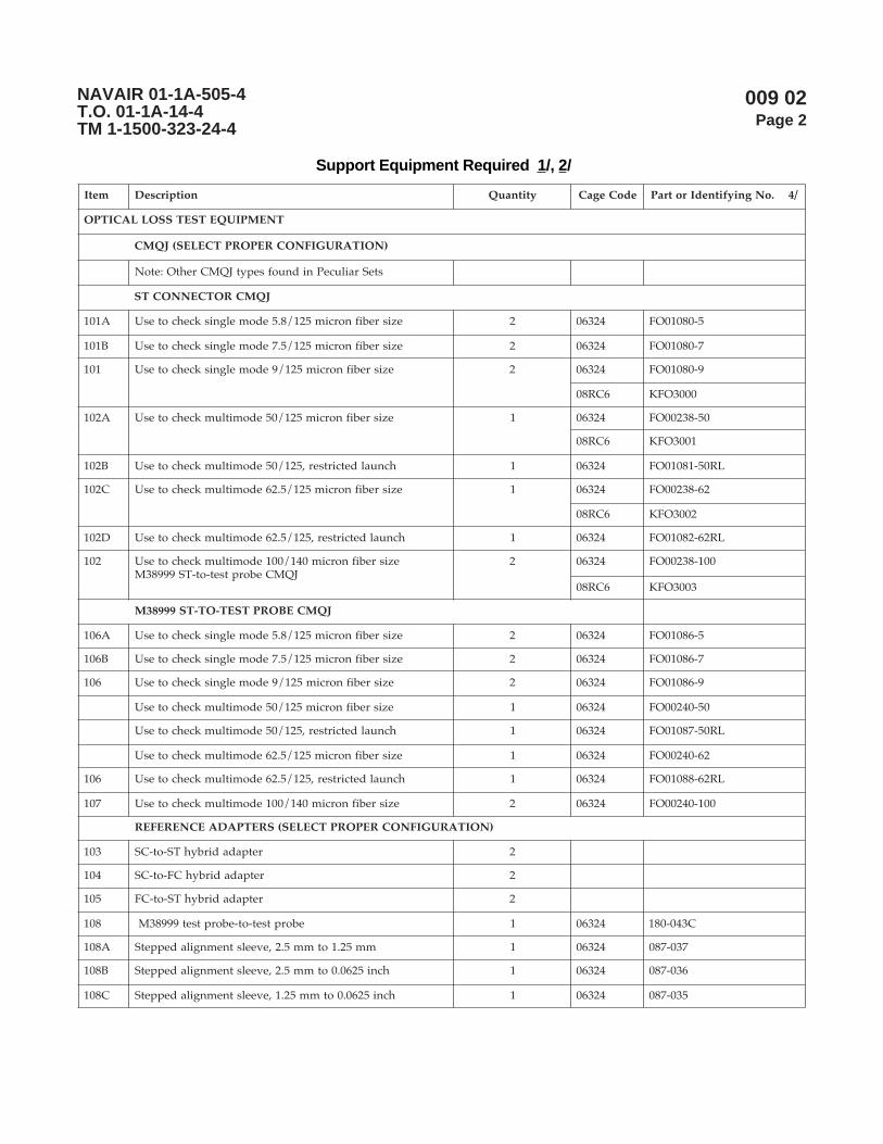
009 02Page 2
NAVAIR 01-1A-505-4T.O. 01-1A-14-4TM 1-1500-323-24-4
Support Equipment Required 1/, 2/
metI noitpircseD ytitnauQ edoCegaC .oNgniyfitnedIrotraP 4/
TNEMPIUQETSETSSOLLACITPO
)NOITARUGIFNOCREPORPTCELES(JQMC
steSrailucePnidnuofsepytJQMCrehtO:etoN
JQMCROTCENNOCTS
A101 ezisrebifnorcim521/8.5edomelgniskcehcotesU 2 42360 5-08010OF
B101 ezisrebifnorcim521/5.7edomelgniskcehcotesU 2 42360 7-08010OF
101 ezisrebifnorcim521/9edomelgniskcehcotesU 2 42360 9-08010OF
6CR80 0003OFK
A201 ezisrebifnorcim521/05edomitlumkcehcotesU 1 42360 05-83200OF
6CR80 1003OFK
B201 hcnualdetcirtser,521/05edomitlumkcehcotesU 1 42360 LR05-18010OF
C201 ezisrebifnorcim521/5.26edomitlumkcehcotesU 1 42360 26-83200OF
6CR80 2003OFK
D201 hcnualdetcirtser,521/5.26edomitlumkcehcotesU 1 42360 LR26-28010OF
201 ezisrebifnorcim041/001edomitlumkcehcotesUJQMCeborptset-ot-TS99983M
2 42360 001-83200OF
6CR80 3003OFK
JQMCEBORPTSET-OT-TS99983M
A601 ezisrebifnorcim521/8.5edomelgniskcehcotesU 2 42360 5-68010OF
B601 ezisrebifnorcim521/5.7edomelgniskcehcotesU 2 42360 7-68010OF
601 ezisrebifnorcim521/9edomelgniskcehcotesU 2 42360 9-68010OF
ezisrebifnorcim521/05edomitlumkcehcotesU 1 42360 05-04200OF
hcnualdetcirtser,521/05edomitlumkcehcotesU 1 42360 LR05-78010OF
ezisrebifnorcim521/5.26edomitlumkcehcotesU 1 42360 26-04200OF
601 hcnualdetcirtser,521/5.26edomitlumkcehcotesU 1 42360 LR26-88010OF
701 ezisrebifnorcim041/001edomitlumkcehcotesU 2 42360 001-04200OF
)NOITARUGIFNOCREPORPTCELES(SRETPADAECNEREFER
301 retpadadirbyhTS-ot-CS 2
401 retpadadirbyhCF-ot-CS 2
501 retpadadirbyhTS-ot-CF 2
801 eborptset-ot-eborptset99983M 1 42360 C340-081
A801 mm52.1otmm5.2,eveelstnemngiladeppetS 1 42360 730-780
B801 hcni5260.0otmm5.2,eveelstnemngiladeppetS 1 42360 630-780
C801 hcni5260.0otmm52.1,eveelstnemngiladeppetS 1 42360 530-780

009 02Page 3
NAVAIR 01-1A-505-4T.O. 01-1A-14-4TM 1-1500-323-24-4
Support Equipment Required 1/, 2/ (cont.)
metI noitpircseD ytitnauQ edoCegaC .oNgniyfitnedIrotraP 4/
(TNEMPIUQETSETSSOLLACITPO tnoc ).
SEIROSSECCA&SECRUOSLACITPO
901 )lliflluf,mn0031&mn058,DEL(ecruoslacitpO 1 35YX0 001SA-A252
A901 )mn0551&0131,DL(ecruoslacitpO 1
011 )yekworran(retpadaCF 1
111 retpadaTS 1
SEIROSSECCA&RETEMREWOPLACITPO
211 )sAaGnImm1,mBd06-ot3+(retemrewoplacitpO 1
311 )COS(ecafretnirotcennoCnO-panS,retpadaCF 1
411 COS,retpadaTS 1
511 COS,99983M,retpadaeborptseT 1
SRETPADAEBORPROTCENNOC 3/
SRETPADAEBORPROTCENNOC99983MNOMMOC
811 P2-P11-3M-1282167.ongwd,P2-P11-3M 1 42360 P2-11-60FN440-081
911 N-S2-R11-3M-1282167.ongwd,N-S2-R11-3M 1 42360 S2-11-70FN440-081
021 P4-P31-3M-1282167.ongwd,P4-P31-3M 1 42360 P4-31-60FN440-081
121 N-S4-R31-3M-1282167.ongwd,N-S4-R31-3M 1 42360 S4-31-70FN440-081
221 P5-P51-3M-1282167.ongwd,P5-P51-3M 1 42360 P5-51-60FN440-081
321 N-S5-R51-3M-1282167.ongwd,N-S5-R51-3M 1 42360 S5-51-70FN440-081
421 P8-P71-3M-1282167.ongwd,P8-P71-3M 1 42360 P8-71-60FN440-081
521 N-S8-R71-3M-1282167.ongwd,N-S8-R71-3M 1 42360 S8-71-70FN440-081
621 P11-P91-3M-1282167.ongwd,P11-P91-3M 1 42360 P11-91-60FN370-081
721 N-S11-R91-3M-1282167.ongwd,N-S11-R91-3M 1 42360 S11-91-70FN370-081
821 P73-P52-3M-1282167.ongwd,P73-P52-3M.onmetisihthtiwdedulcnierasretpadaowT:etoN
1 42360 PA73-52-60FN370-081PB73-52-60FN370-081
921 N-S73-R52-3M-1282167.ongwd,N-S73-R52-3M.onmetisihthtiwdedulcnierasretpadaowT:etoN
1 42360 SA73-52-70FN370-081SA73-52-70FN370-081
SRETPADAEBORPROTCENNOC99983MCIFICEPSTFARCRIA/MARGORPTNERRUC
702 A-S8-P71-3M-1282167.ongwd,A-S8-P71-3M 1 42360 S8-71-60FN440-081
802 A-P8-R71-3M-1282167.ongwd,A-P8-R71-3M 1 42360 AP8-71-70FN440-081
902 P61-P12-3M-1282167.ongwd,P61-P12-3M 1 42360 P61-12-60FN270-081
012 P45-P32-3M-1282167.ongwd,P45-P32-3M 1 42360 P45-32-60FN370-081
112 N-S45-R32-3M-1282167.ongwd,N-S45-R32-3M 1 42360 S45-32-70FN370-081
212 N-P45-R32-3M-1282167.ongwd,N-P45-R32-3M 1 42360 P45-32-00FN370-081

009 02Page 4
NAVAIR 01-1A-505-4T.O. 01-1A-14-4TM 1-1500-323-24-4
Support Equipment Required 1/, 2/ (cont.)
metI noitpircseD ytitnauQ edoCegaC .oNgniyfitnedIrotraP 4/
SRETPADAEBORPROTCENNOC 3/ ).tnoc(
SRETPADAEBORPROTCENNOC99983MCIFICEPSTFARCRIA/MARGORPTNERRUC ).tnoc(
312 C-S92-R52-3M-1282167.ongwd,C-S92-R52-3M 1 42360 CS92-52-70FN440-081
412 P34-P52-3M-1282167.ongwd,P34-P52-3M 1 42360 P34-52-60FN440-081
512 N-S34-R52-3M-1282167.ongwd,N-S34-R52-3M 1 42360 S34-52-70FN440-081
)EPYTEMASEHTFOSROTCENNOCELURREFELGNIS2ETAM(,ELURREFELGNIS,SRETPADA
10ATS dezidegguR,STOC,edomelgnis,retpadaTS-ot-TS 1
20ATS ,STOC,norcim521,edomitlum,retpadaTS-ot-TSdezideggur
1
10ACS xelpmis,STOC,edomelgnis,retpadaCS-ot-CS 1
20ACS xelpmis,STOC,norcim521,edomitlum,retpadaCS-ot-CS 1
10ACL xelpud,STOC,edomelgnis,retpadaCL-ot-CL 1
20ACL xelpud,STOC,edomitlum,retpadaCL-ot-CL 1
SLOOTLATNEMELPPUS
SROTCENNOC99983MNIINIMRETEVOMER&TRESNIOTSLOOT
141 )citsalp(5/&4/40592Mroflootnoitcartxe&noitresnI 3 94318 30-41/96918M
241 )latem(5/&4/40592MlootnoitresnI 1 94318 702-8/96918M
341 )latem(5/&4/40592MlootnoitcartxE 1 94318 802-8/96918M
441 )lanoitpo(lootlavomertsissainimreT 1 6CR80 0511-1270
ECNEREFERYBDEDULCNITNEMPIUQETROPPUS
)20800PW(gninaelClaunaMdna)10800PW(noitcepsnIroftnempiuqEtroppuSeeS
1/ tseTkniLlacitpO,tfarcriA,citpOrebiF,teStseT,2282167gniwarDAESVANrepdeificepsesohteraelbatsihtnismetIrepdeificepsesohteraelbatsihtnisretpadaecnereferdnasretpadaeborprotcennoc,JQMCehT.seirosseccA&tnempiuqEotsnoisiverynA.citpOrebiF,tnempiuqEtsetroF,)JQMC(srepmuJytilauQtnemerusaeMSTOC,1282167gniwarDAESVAN
.sgniwardesehtrofssecorpecnatpecca3.1.8.4RIAVANehthguorhtdevorppaeradnanidnuofeblliwsmetieseht
2/ noitcepsnigninaelcdnemmoceR.emulovsihtnigninaelCrednudetsileragninaelcrotcennocroftnempiuqenoitcepsnI.spiteborpnoitcepsnielbacilppahtiw)SIVOF(metsySnoitcepsnIoediVcitpOrebiFasedulcnitnempiuqe
3/ :)rotcennoc99983-LTD-LIMehthtiwesurof(snoitangisedretpadaeborprotcennoC:swollofsaera)N-S2-R11-3Msahcus(noitpircsednisnoitangiseD
piteborprotcennocehthtiwelbitapmocrotcennocinimretelpitlumfoepyT=3M)elcatpecer=R,gulp=P(epytydobdnaezisllehsretpadaeborprotcennoC=R11)tekcos=S,nip=P(ytivactresnirofepytinimretdnaseitivactresniforebmuN=S2
epytgulP.ylnosretpadaeborpepytelcatpecerrof,elbacilppaeraFhguorhtAosla,lamron=N(noitisopgniyek=N.)selcatpecer99983Mdeyekynatifnacsretpadaeborprotcennoc
4/ .metiehtrofstnemeriuqerllufehtteemotdeifitnedineebevahtahtstcudorp'srerutcafunamroferadetsilsrebmuntraPdenimretedebotytilibacilppA.tesehtgnittiftuorofstcudorptnelaviuqeecudorpotemoclewerasrerutcafunamrehtO
.ssecorpylppuselbacilppaehthguorht

009 02Page 5
NAVAIR 01-1A-505-4T.O. 01-1A-14-4TM 1-1500-323-24-4
Materials Required
Cleaning consumable supplies only. Cleaning suppliesare listed under Manual Cleaning Procedures in thisvolume (see WP 008 02).
1. INTRODUCTION.
2. This work package has an alternate method thatis used by personnel for performing optical lossmeasurements on non-aircraft platforms such as surfaceship and submarine platforms. This is a valid methodand is presented in this work package for aircraftpersonnel familiarization when involved with“cross-platform” efforts. Measurements P1 and P3 ofthis test are for the optical loss measurement on theentire cable harness (P3-P1). This method conforms tothe optical power loss measurement of TIA/EIA-526-14,Method B. Measurements P1 and P2 of this test are for afield-check of the CMQJ (P2-P1). The measurement valueobtained for measurement P2 is not included in theoptical loss measurement. Measurements P1 and P2, forthe field check on the CMQJ, differs from measurementsP1 and P3, for the optical loss test done on the cableharnesses. The CMQJ test (field check) is done at oneconnector interface. Optical loss test is done on entirecable harness (two or more interfaces). This methodmay be generalized to apply to other connectorconfigurations such as FC-to-Test Probe CMQJ’s byreplacing the word “ST” with “FC” or other connectortype and performing the steps listed below.
3. Optical Loss Measurement, One Jumper Method.
WARNING
DO NOT stare into the end of an optical fiberconnected to an LED or laser diode. Light maynot be visible but can still damage the eye.
CAUTION
Inspect, clean (if needed) and re-inspect aftercleaning a connector/terminus ferrule andmating instrument adapters/interfacesimmediately before each mating to ensureaccurate and reproducible results. Perform theinspection and cleaning per WP 008 02.
NOTE
The number one cause for an increased opticalloss, after an insufficiently tight connection, isdirt and film deposits. No single cleaningmethod has been found to date that willguarantee a clean end face on the ferrule.Magnified visual inspection together withcleaning is important, when practical. Visualinspection is done using a FOVIS.Recommended cleaning supplies are listed inWP 008 02.
Inspection of an instrument interface/opticalsource transmit port. To inspect an opticaltransmit port, an adapter (such as an ST adapter)must be installed on the instrument interfaceport. The FOVIS ST inspection “tip” will easilymate to this. The image of a ferrule end face,from a fiber pigtail connected to a LD or LED,will be observed on the FOVIS. Surroundingthe fiber core and cladding, an image of theoptical port backing/mounting panel will beobserved. This mounting panel may be metal,not ceramic. As a result, more roughenedsurface features may be mistaken as dirt/particles. Inspection and cleaning, using themethods specified in WP 008 02, may be used asthe discriminator to differentiate dirt and filmdeposits from roughened surface imperfections.The latter can be identified by being unchangedafter cleaning and appearing only outside thefiber surface.
009 02Page 6
NAVAIR 01-1A-505-4T.O. 01-1A-14-4TM 1-1500-323-24-4
Inspection of an instrument interface/opticalreceiver port. To inspect an optical receiverport, an adapter (such as an ST adapter) mustbe installed on the instrument interface port.The FOVIS ST inspection “tip” will easily mateto this. There is a photodetector behind theoptical connection port on an optical powermeter or the Rx port on an OLTS (optical losstest set). The image of this large photodetectorwill be displayed by the FOVIS. No image willbe viewed of a ferrule end with a fiber in thecenter. Adjust the FOVIS focus until somedistinguishable features on the photodetectorsurface or the surrounding surface are observed.Dirt or film deposits on the photodetectorsurface may now be seen. Surrounding thephotodetector, some of the optical port backing/mounting panel may be observed. Thismounting panel may be metal, not ceramic. Asa result, a more roughened surface featuresmay be mistaken as dirt/particles. Inspectionand cleaning, using the methods specified inWP 008 02, may be used as the discriminator todifferentiate dirt and film deposits fromroughened surface imperfections. The lattercan be identified by being unchanged aftercleaning and appearing only outside thephotodetector surface.
During handling, all the cables shall beprotected from kinks, twists, crushing and sharpbends (see Handling Practices WP 006 01).
Ensure the test equipment calibration is current.
CMQJs wear out. CMQJs must be maintainedby inspection and cleaning per WP 008 01 andWP 008 02. CMQJs must be replaced when theyperform poorly after proper inspection andcleaning per WP 008 01 and WP 008 02.
Connector adapters accumulate dirt. Connectoradapters must be maintained by inspectionand cleaning per WP 008 01 and WP 008 02.
Always cover connectors (with ESD or dustcaps) immediately after unmating. Never usetape to cover connectors with fiber optic terminiin them.
For measurements on aircraft, or wherever toolcontrol and FOD are a concern, the P1 (seeFigure 1) and P2 (see Figure 2) measurementsof this procedure can be done in a work centerafter access to the cable harness to test has beenaccomplished. Then the optical loss tools canbe left all connected as shown in Figure 2 (withoptical source and power meter energized) andtaken out to the cable harness to test. Inspectionand cleaning (WP 008 02) will still need to beperformed at the cable harness to test.
a. Safety Summary. The safety precautions inWP 004 01 shall be observed. The following safetyprecautions are restated for emphasis:
(1) Do not touch the ends of the fiber as theymay be razor sharp. Wash your hands before and afterhandling bare fiber.
(2) Do not stare into the end of a fiber untilverifying that the fiber is not connected to a laser lightsource or LED.
b. First Power Measurement (P1).
NOTE
Before making loss measurements, make surethat both the light source and the power meterhave been energized for at least 5 minutes tohave stable performance.
CMQJ(s) used must be compatible withapplicable requirements specified in thePlatform maintenance manual for fiber sizeand ferrule end face polish. Only like polishtypes (PC/PC or NC/NC) should be matedtogether. Generally, if the fiber size in the cableharness being tested is multimode 50/125 micron or 62.5/125 micron, then ensurethat CMQJ1 is the one with the restricted launchcondition (CMQJ that states usage is for launchend only).

009 02Page 7
NAVAIR 01-1A-505-4T.O. 01-1A-14-4TM 1-1500-323-24-4
Test probe CMQJ insertion and removal iscovered in WP 009 07.
Different types of CMQJs may be used in thisprocedure. Step (1) assumes that aMIL-DTL-38999 connector is on each end of thecable harness. CMQJ selection is provided basedon the type of connector on the cable harness.For testing a cable harness with aMIL-DTL-38999 connector, the ST-to-Test probeCMQJ is used For testing a cable harness witha ST connector, a ST-to-ST CMQJ is used for theend of the cable harness. For testing a cableharness with other types of single ferruleconnectors, a ST-to-applicable single ferruleconnector CMQJ is used for the end the cableharness with the applicable single ferruleconnector pigtail.
The light source and optical power meter mustbe compatible with applicable requirementsspecified in Platform maintenance manual (suchas operating wavelength). If Platformrequirements are not applicable, a laser lightsource is recommended for use with singlemode optical fiber cable assembly, link lossmeasurements.
The source and power meter should be stable(power meter reading not changing by morethan +/- 0.05 dBm) over a measurement. If thisstability is not observed; check batteries, CMQJsand general test setup.
(1) Turn light source and power meter on. Letthem stabilize for at least 5 minutes before making anymeasurements.
(2) Set power meter display units to dBm.
Figure 1. First Power Measurement (P1) Setup

009 02Page 8
NAVAIR 01-1A-505-4T.O. 01-1A-14-4TM 1-1500-323-24-4
(3) Set light source wavelength (λ) to matchapplicable Platform maintenance manual requirementsand make sure any source modulation is off.
CAUTION
Inspect, clean (if needed) and re-inspect aftercleaning a connector/terminus ferrule andmating instrument adapters/interfacesimmediately before each mating to ensureaccurate and reproducible results. Perform theinspection and cleaning per WP 008 02.
NOTE
The number one cause for an increased opticalloss, after an insufficiently tight connection, isdirt and film deposits. No single cleaningmethod has been found to date that willguarantee a clean end face on the ferrule.Magnified visual inspection together withcleaning is important, when practical. Visualinspection is done using a FOVIS.Recommended cleaning supplies are listed inWP 008 02.
(4) Designate one of the ST-to-Test ProbeCMQJ’s as CMQJ1 (see Figure 1 for setup).
(5) Designate the ST end of the CMQJ1 as "A"and the Test Probe end as "B".
(6) Place a ST adapter on the optical source.
(7) Place a Test Probe adapter on the powermeter.
(8) Connect end "A" of CMQJ1 immediately tothe optical source.
(9) Connect end "B" of CMQJ1 immediately tothe power meter.
(10) Observe power meter reading. Whenreading is stable (not changing by more than +/- 0.05dBm), note the value as P1. If the value is below thespecification of the light source (see operator manual)by more than 0.5dBm , check the batteries in the lightsource and check CMQJ1.
(11) "Zero out" the power meter (see operatormanual). When properly "Zeroed-out" the power meterwill read a value of zero dB (within +/- 0.05 dB).
Figure 2. Second Power Measurement (P2) Setup and CMQJ Field Check (P
2-P
1)

009 02Page 9
NAVAIR 01-1A-505-4T.O. 01-1A-14-4TM 1-1500-323-24-4
c. Second Power Measurement (P2) & CMQJ FieldCheck (P2-P1).
NOTE
From this point forward, the power metershould be displaying values in units of dB andnot dBm.
The time delay between the measurement of P1and P2 shall be kept to a minimum to preventinaccurate measurements.
The value obtained for the second powermeasurement, P2 should be consistent from testto test. When making multiple cable harnessloss measurements, the P2 measurement can berepeated to verify the test setup is still valid.Generally, this P2 value should not change bymore than +/- 0.1 dB. Changes in the secondpower measurement greater than +/- 0.1 dBindicate either a dirty/defective CMQJ, adefective light source or an unstable powermeter. If changes in the second powermeasurement greater than +/- 0.1 dB occur,clean or replace the CMQJ and repeat the secondpower measurement.
NOTE
The value obtained for the second powermeasurement (P2), should be less than the valueobtained for the first power measurement (P1).A value of the second power measurement (P2)greater than the value of the first powermeasurement (P1) indicates that either adefective or dirty CMQJ was used for the firstpower measurement (P1). If a value for thesecond power measurement (P2) greater thanthe value of the first power measurement (P1) isobtained, clean or replace CMQJ1 and repeatthe first power measurement (P1) and the secondpower measurement (P2).
Select the appropriate type of reference adapterbased on the two connectors/test probe CMQJsbeing connected. A test probe to test probeadapter is used when probe CMQJs are used. Ahybrid adapter is used when each CMQJ has adifferent connector type on the end. Forinstance, a test probe-to-1.25 mm adapter isused to connect the CMQJ ends together of atest probe to a single ferrule connector CMQJand one ST-to-test probe CMQJ.
Test probe CMQJ insertion and removal iscovered in WP 009 07.
(1) Designate another one of the ST-to-TestProbe CMQJ’s as CMQJ2 (see Figure 2 for setup).
(2) Designate the ST end of the ST-to-Test ProbeCMQJ, CMQJ2, as "A" and the Test Probe end as "B".
CAUTION
Inspect, clean (if needed) and re-inspect aftercleaning a connector/terminus ferrule andmating instrument adapters/interfacesimmediately before each mating to ensureaccurate and reproducible results. Perform theinspection and cleaning per WP 008 02.
NOTE
The number one cause for an increased opticalloss, after an insufficiently tight connection, isdirt and film deposits. No single cleaningmethod has been found to date that willguarantee a clean end face on the ferrule.Magnified visual inspection together withcleaning is important, when practical. Visualinspection is done using a FOVIS.Recommended cleaning supplies are listed inWP 008 02.
(3) Detach end "B" of CMQJ1 from the powermeter (see Figure 1).
(4) Connect end "B" of CMQJ1 immediatelyinto one end of the reference adapter (see Figure 2).
009 02Page 10
NAVAIR 01-1A-505-4T.O. 01-1A-14-4TM 1-1500-323-24-4
(5) Remove the Test Probe adapter from thepower meter.
(6) Place a ST adapter on the power meter.
(7) Connect end "A" of CMQJ2 immediately tothe power meter.
(8) Connect end "B" of CMQJ2 immediately tothe other end of the reference adapter.
(9) Observe power meter reading. Whenreading is stable (not changing by more than+/- 0.05 dB), note the value as P2. If this stability is notobserved; check batteries, CMQJs and general test setup.P2 should be a value within +0.1 to -0.5 dB range (if notcheck setup for dirty/worn components).
(a) If P2 is within the +0.1 dB to -0.5 dBrange, continue (the P2 measurement is acceptable).
(b) If P2 is higher than +0.1 dB (e.g. +0.3 dB),or If P2 is lower than -0.5 dB (e.g. -0.7 dB ); then checksetup for dirty/worn components and repeat P1 and P2measurements.
NOTE
The P2 measurement here, is not "zeroed out" asit is in the two jumper optical loss measurementmethod. This is the difference between the twojumper and one jumper optical lossmeasurement methods.
For measurements on aircraft, or wherever toolcontrol and FOD are a concern, the P1 (seeFigure 1) and P2 (see Figure 2) measurementsof this procedure can be done in a work centerafter access to the cable harness to test has beenaccomplished. Then the optical loss tools canbe left all connected as shown in Figure 2 (withoptical source and power meter energized) andtaken out to the cable harness to test. Inspectionand cleaning (WP 008 02) will still need to beperformed at the cable harness to test.
d. Test Measurement (P3) and Cable HarnessOptical Loss (P3-P1).
CAUTION
Make sure that the proper connector probeadapter is used before attaching it to aMIL-DTL-38999 connector with fiber optictermini. Incorrect connector probe adapter mayresult in damage to the connector termini.
NOTE
Use the adapter that matches the connectors onthe cable harness to be tested. For cableharnesses under test terminated withMIL-DTL-38999 connectors, a connector probeadapter is used at each end to connect the testprobe end of the CMQJ to the MIL-DTL-38999connector. For cable harnesses under testterminated with ST connector pigtails at oneend, a ST-to-ST adapter is required to connectthe CMQJ to the ST connector pigtail end of thecable harness under test. For cable harnessesunder test terminated with SC or other singleferrule, fiber optic connectors on one end, ahybrid adapter is required to connect the CMQJto the pigtail end of the cable harness undertest.
The value obtained for the test measurement(P3), should be less than the value obtained forthe second power measurement (P2). A value ofthe test measurement power (P3) greater thanthe value of the second power measurement(P2) indicates that either a defective or dirtyCMQJ was used for the second powermeasurement (P2). If a value for the testmeasurement (P3) greater than the value of thesecond power measurement (P2) is obtained,clean or replace CMQJ1 and repeat the secondpower measurement (P2) and the testmeasurement (P3).

009 02Page 11
NAVAIR 01-1A-505-4T.O. 01-1A-14-4TM 1-1500-323-24-4
(1) Identify mating connector probe adaptersfor each end of the cable assembly/harness under test.
(2) Attach the connector probe adapters to theconnectors on each end of the cable harness under test(see Figure 3 for setup).
(3) Remove end "B" of CMQJ1 from the referenceadapter, and immediately place end "B" of CMQJ1 intothe proper position of the connector probe adapter.
(4) Remove end "B" of CMQJ2 from the referenceadapter, and immediately place end "B" of CMQJ2 intothe proper position of the second connector probeadapter.
(5) Observe power meter reading. When thereading is stable (not changing by more than +/- 0.05dB), note the value as P3. If this stability is not observed;check batteries, CMQJs and general test setup. Recordoptical power measurement P3.
NOTE
If optical loss is unacceptable, and the testsetup is valid, check connectors for propermating and inspect /clean(if necessary) allferrule end faces of the cable under test andCMQJs (see WP 008 02).
(6) Record optical loss. Generally, optical loss isacceptable if P3 is less than or equal to the specified
maximum acceptable optical loss for the cable harness.See specific Platform maintenance manual for themaximum acceptable optical loss value. Optical lossvalues will be specified in units of dB not dBm.
NOTE
When making multiple measurements formultiple connector positions, inspect/clean(WP 008 02) ends "B" of the two CMQJs and thenext selected termini of the cable under test.
Verification of the test setup integrity may bedone after any measurement by rechecking theP2 measurement with the reference adapter.Changes in the second power measurementgreater than +/- 0.1 dB indicate either a dirty/defective CMQJ, a defective light source or anunstable power meter. If changes in the secondpower measurement greater than +/- 0.1 dBoccur, clean or replace the CMQJ and repeat theP1 and P2 measurements.
Verification of a CMQJ may be done after anymeasurement by following the CMQJ fieldcheck (WP 009 03) , or by following the stepsfirst for the first power measurement (P1), thenfor the second power measurement (P2).
Figure 3. Test Measurement (P3) and Cable Harness Optical Loss (P3-P1)

009 02Page 12
NAVAIR 01-1A-505-4T.O. 01-1A-14-4TM 1-1500-323-24-4
(7) For each connector/terminus position to betested, remove ends "B" of the two CMQJs then connectthem at the next position to be tested and redo Step (6).
NOTE
Specific Platform requirements may not requirean additional loss measurement of multimodefiber in the opposite direction.
General practice is to also measure multimodefiber cables in the opposite direction. Generalpractice does not measure single-mode fibercables in the opposite direction. Swapping theconnections of the CMQJs connected to thecable harness under test, accomplishes thisdirectionality change (if the CMQJs are notdetached from the optical source and powermeters).
(8) Redo step (6) for each connector/terminusposition to be tested in the opposite direction.Inspecting/cleaning (WP 008 02) ends "B" of the twoCMQJs and the termini is required.
(9) Once testing is completed, secure testequipment. Install protective caps (dust covers) over allCMQJs, cable harness connectors and test equipmentports.
e. Determinations for Acceptance of Optical Loss.
(1) Optical loss is acceptable (in each directionfor multimode cable harness), if the measured opticalloss does not exceed the maximum acceptable opticalloss specified for the cable harness. Specific Platformrequirements may not require an additional lossmeasurement of multimode fiber in the oppositedirection. See Platform maintenance manual for theacceptable optical loss value(s). Optical loss values willbe specified in units of dB not dBm.
(2) If the measured optical loss (in eitherdirection for multimode cable harnesses) is above themaximum acceptable optical loss, then inspect andclean (WP 008 01, and WP 008 02) all the connections
and retest. If the optical loss (in either direction formultimode cable harnesses) is still unacceptable, thenrepair/replacement of cable is needed (See WP 012 01,and WP 013 01).
(3) If the maximum acceptable optical loss forthe cable harness is not specified, record the length ofthe cable from the vendor’s data or as measured. If thecable length is less than 10 meters, then a value of 0 maybe recorded. If the cable length is unknown a value of"0/unknown" may be recorded.
NOTE
The term BCA = Total cable harness optical lossin dB. Here, BCA = P3 (recorded previously)
The term MAL= Maximum Acceptable Loss.The term ACA = Maximum Attenuation of theCable. The term L = Length of the cable. Theterm Ns = Number of splices. The term Ls = Lossof a splice (max.). The term Nco = Number ofconnectors. The term Lco = Loss of a connector(max.).
(a) Determine if the measurement isacceptable. Compare the measured optical loss (in eachdirection for multimode cable harness) to the maximumallowable optical loss. The maximum allowable opticalloss is calculated from the maximum specifiedcomponent optical loss values using the formula;MAL = AcaL + NcoLco + NsLs
1 The cable harness is consideredacceptable if the measured optical loss (in each directionfor multimode cable assemblies) is equal to or less thanthe maximum acceptable optical loss.
2 If the measured optical loss (in eitherdirection for multimode cable harnesses) is above themaximum acceptable optical loss, then inspect andclean (see WP 008 01, and WP 008 02) all the connectionsand retest. If the optical loss (in either direction formultimode cable harnesses) is still unacceptable, thenrepair/replacement of cable is needed (See WP 012 01and WP 013 01).

009 03Page 1
NAVAIR 01-1A-505-4T.O. 01-1A-14-4TM 1-1500-323-24-4
CMQJ Field Check Method (ST-to-ST CMQJ)
Reference Material
Definitions ............................................................................................................................. WP 003 01Safety .................................................................................................................................... WP 004 01Handling ................................................................................................................................ WP 006 01Inspection .............................................................................................................................. WP 008 01Manual Cleaning Procedures ................................................................................................. WP 008 02
Alphabetical Index
Subject Page No.
CMQJ Field Check Method (ST-to-ST CMQJ) .................................................................................... 4Acceptance of CMQJ .................................................................................................................... 8Determine If End "A" Optical Loss is Acceptable .......................................................................... 7Determine if End "B" Optical Loss is Acceptable .......................................................................... 8Reference Measurement (P
1) ......................................................................................................... 5
Repeat Reference Measurement P1
................................................................................................ 8Safety Summary ............................................................................................................................ 5Test Measurement End "A" of CMQJ Under Test (P
2) .................................................................. 7
Test Measurement End "B" of CMQJ Under Test (P2) ................................................................... 8
Introduction .......................................................................................................................................... 4
Record of Applicable Technical Directives
None
13 August 2004

009 03Page 2
NAVAIR 01-1A-505-4T.O. 01-1A-14-4TM 1-1500-323-24-4
Support Equipment Required 1/, 2/
metI noitpircseD ytitnauQ edoCegaC .oNgniyfitnedIrotraP 3/
TNEMPIUQETSETKCEHCDLEIFJQMC
)noitarugifnocreporptceles(JQMCsteSrailucePnidnuofsepytJQMCrehtO:etoN
JQMCRPOTCENNOCTS
A101 ezisrebifnorcim521/8.5edomelgniskcehcotesU 2 42360 5-08010OF
B101 ezisrebifnorcim521/5.7edomelgniskcehcotesU 2 42360 7-08010OF
101 ezisrebifnorcim521/9edomelgniskcehcotesU 2 42360 9-08010OF
6CR80 0003OFK
A201 ezisrebifnorcim521/05edomitlumkcehcotesU 1 42360 05-83200OF
6CR80 1003OFK
B201 hcnualdetcirtser,521/05edomitlumkcehcotesU 1 42360 LR05-18010OF
C201 ezisrebifnorcim521/5.26edomitlumkcehcotesU 1 42360 26-83200OF
6CR80 2003OFK
D201 hcnualdetcirtser,521/5.26edomitlumkcehcotesU 1 42360 LR26-28010OF
201 ezisrebifnorcim041/001edomitlumkcehcotesUJQMCeborptset-ot-TS99983M
2 42360 001-83200OF
6CR80 3003OFK
JQMCEBORPTSET-OT-TS99983M
A601 ezisrebifnorcim521/8.5edomelgniskcehcotesU 2 42360 5-68010OF
B601 ezisrebifnorcim521/5.7edomelgniskcehcotesU 2 42360 7-68010OF
601 ezisrebifnorcim521/9edomelgniskcehcotesU 2 42360 9-68010OF
ezisrebifnorcim521/05edomitlumkcehcotesU 1 42360 05-04200OF
hcnualdetcirtser,521/05edomitlumkcehcotesU 1 42360 LR05-78010OF
ezisrebifnorcim521/5.26edomitlumkcehcotesU 1 42360 26-04200OF
601 hcnualdetcirtser,521/5.26edomitlumkcehcotesU 1 42360 LR26-88010OF
701 ezisrebifnorcim041/001edomitlumkcehcotesU 2 42360 001-04200OF
)NOITARUGIFNOCREPORPTCELES(SRETPADAECNEREFER
301 retpadadirbyhTS-ot-CS 2
401 retpadadirbyhCF-ot-CS 2
501 retpadadirbyhTS-ot-CF 2
801 eborptset-ot-eborptset99983M 1 42360 C340-081
A801 mm52.1otmm5.2,eveelstnemngiladeppetS 1 42360 730-780
B801 hcni5260.0otmm5.2,eveelstnemngiladeppetS 1 42360 630-780
C801 hcni5260.0otmm52.1,eveelstnemngiladeppetS 1 42360 530-780

009 03Page 3
NAVAIR 01-1A-505-4T.O. 01-1A-14-4TM 1-1500-323-24-4
Support Equipment Required 1/, 2/ (cont.)
metI noitpircseD ytitnauQ edoCegaC .oNgniyfitnedIrotraP 3/
(TNEMPIUQETSETSSOLLACITPO tnoc ).
SEIROSSECCA&SECRUOSLACITPO
901 )lliflluf,mn0031&mn058,DEL(ecruoslacitpO 1 35YX0 001SA-A252
A901 )mn0551&0131,DL(ecruoslacitpO 1
011 )yekworran(retpadaCF 1
111 retpadaTS 1
SEIROSSECCA&RETEMREWOPLACITPO
211 )sAaGnImm1,mBd06-ot3+(retemrewoplacitpO 1
311 )COS(ecafretnirotcennoCnO-panS,retpadaCF 1
411 COS,retpadaTS 1
511 COS,99983M,retpadaeborptseT 1
)EPYTEMASEHTFOSROTCENNOCELURREFELGNIS2ETAM(,ELURREFELGNIS,SRETPADA
10ATS dezidegguR,STOC,edomelgnis,retpadaTS-ot-TS 1
20ATS dezideggur,STOC,norcim521,edomitlum,retpadaTS-ot-TS 1
10ACS xelpmis,STOC,edomelgnis,retpadaCS-ot-CS 1
20ACS xelpmis,STOC,norcim521,edomitlum,retpadaCS-ot-CS 1
10ACL xelpud,STOC,edomelgnis,retpadaCL-ot-CL 1
20ACL xelpud,STOC,edomitlum,retpadaCL-ot-CL 1
ECNEREFERYBDEDULCNITNEMPIUQETROPPUS
)20800PW(gninaelCdnaHlaunaMdna)10800PW(noitcepsnIroftnempiuqEtroppuSeeS
1/ tseTkniLlacitpO,tfarcriA,citpOrebiF,teStseT,2282167gniwarDAESVANrepdeificepsesohteraelbatsihtnismetIrepdeificepsesohteraelbatsihtnisretpadaecnereferdnasretpadaeborprotcennoc,JQMCehT.seirosseccA&tnempiuqEotsnoisiverynA.citpOrebiF,tnempiuqEtsetroF,)JQMC(srepmuJytilauQtnemerusaeMSTOC,1282167gniwarDAESVAN
.sgniwardesehtrofssecorpecnatpecca3.1.8.4RIAVANehthguorhtdevorppaeradnanidnuofeblliwsmetieseht
2/ noitcepsnigninaelcdnemmoceR.emulovsihtnigninaelCrednudetsileragninaelcrotcennocroftnempiuqenoitcepsnI.spiteborpnoitcepsnielbacilppahtiw)SIVOF(metsySnoitcepsnIoediVcitpOrebiFasedulcnitnempiuqe
3/ .metiehtrofstnemeriuqerllufehtteemotdeifitnedineebevahtahtstcudorp'srerutcafunamroferadetsilsrebmuntraPdenimretedebotytilibacilppA.tesehtgnittiftuorofstcudorptnelaviuqeecudorpotemoclewerasrerutcafunamrehtO
.ssecorpylppuselbacilppaehthguorht

009 03Page 4
NAVAIR 01-1A-505-4T.O. 01-1A-14-4TM 1-1500-323-24-4
Materials Required
Cleaning consumable supplies only. Cleaning suppliesare listed under Manual Cleaning Procedures in thisvolume (see WP 008 02).
1. INTRODUCTION.
2. This work package is for a field check of theCMQJ based on periodicity or usage. Initial acceptancetest of the CMQJ is to be done per Method 6F1 of MIL-STD-2042. Field verification test on the CMQJ differsfrom optical loss test done on cable harnesses. ThisCMQJ test is done at each connector interface. Anyexception is noted below. Optical loss test is done onentire cable harness (two or more interfaces). This CMQJfield check may be performed on different CMQJconfigurations (such as the ST-to-test probe CMQJ) ifthe mating adapters are available for attaching the twoCMQJ’s (such as the reference adapter for the ST-to-testprobe CMQJ) and for interface at the power meter.
3. CMQJ Field Check Method (ST-to-ST CMQJ).
WARNING
DO NOT stare into the end of an optical fiberconnected to an LED or laser diode. Light maynot be visible but can still damage the eye.
CAUTION
Inspect, clean (if needed) and re-inspect aftercleaning a connector/terminus ferrule andmating instrument adapters/interfacesimmediately before each mating to ensureaccurate and reproducible results. Perform theinspection and cleaning per WP 008 02.
NOTE
The number one cause for an increased opticalloss, after an insufficiently tight connection, isdirt and film deposits. No single cleaningmethod has been found to date that willguarantee a clean end face on the ferrule.Magnified visual inspection together withcleaning is important, when practical. Visualinspection is done using a FOVIS.Recommended cleaning supplies are listed inWP 008 02.
Inspection of an instrument interface/opticalsource transmit port. To inspect an opticaltransmit port, an adapter (such as an ST adapter)must be installed on the instrument interfaceport. The FOVIS ST inspection “tip” will easilymate to this. The image of a ferrule end face,from a fiber pigtail connected to a LD or LED,will be observed on the FOVIS. Surroundingthe fiber core and cladding, an image of theoptical port backing/mounting panel will beobserved. This mounting panel may be metal,not ceramic. As a result, more roughenedsurface features may be mistaken as dirt/particles. Inspection and cleaning, using themethods specified in WP 008 02, may be used asthe discriminator to differentiate dirt and filmdeposits from roughened surface imperfections.The latter can be identified by being unchangedafter cleaning and appearing only outside thefiber surface.

009 03Page 5
NAVAIR 01-1A-505-4T.O. 01-1A-14-4TM 1-1500-323-24-4
Inspection of an instrument interface/opticalreceiver port. To inspect an optical receiverport, an adapter (such as an ST adapter) mustbe installed on the instrument interface port.The FOVIS ST inspection “tip” will easily mateto this. There is a photodetector behind theoptical connection port on an optical powermeter or the Rx port on an OLTS (optical losstest set). The image of this large photodetectorwill be displayed by the FOVIS. No image willbe viewed of a ferrule end with a fiber in thecenter. Adjust the FOVIS focus until somedistinguishable features on the photodetectorsurface or the surrounding surface are observed.Dirt or film deposits on the photodetectorsurface may now be seen. Surrounding thephotodetector, some of the optical port backing/mounting panel may be observed. Thismounting panel may be metal, not ceramic. Asa result, a more roughened surface featuresmay be mistaken as dirt/particles. Inspectionand cleaning, using the methods specified inWP 008 02, may be used as the discriminator todifferentiate dirt and film deposits fromroughened surface imperfections. The lattercan be identified by being unchanged aftercleaning and appearing only outside thephotodetector surface.
Ensure the test equipment calibration is current.
CMQJs wear out. CMQJs must be maintainedby inspection and cleaning per WP 008 01 andWP 008 02. CMQJs must be replaced when theyperform poorly after proper inspection andcleaning per WP 008 01 and WP 008 02.
Connector adapters accumulate dirt. Connectoradapters must be maintained by inspectionand cleaning per WP 008 01 and WP 008 02.
During handling, all the cables shall beprotected from kinks, twists, crushing, andsharp bends (see Handling PracticesWP 006 01).
a. Safety Summary. The safety precautions inWP 004 01 shall be observed. The following safetyprecautions are restated for emphasis:
(1) Do not touch the ends of the fiber as theymay be razor sharp. Wash your hands before and afterhandling bare fiber.
(2) Do not stare into the end of a fiber untilverifying that the fiber is not connected to a laser lightsource or LED.
b. Reference Measurement (P1).
NOTE
Before making loss measurements, make surethat both the light source and the power meterhave been energized for at least 5 minutes tohave stable performance.
CMQJ(s) used must be compatible withapplicable requirements specified in Platformmaintenance manual for fiber size and ferruleend face polish. Only like polish types (PC/PCor NC/NC) should be mated together.Generally, if the fiber size in the cable harnessbeing tested is multimode 50/125 micron or62.5/125 micron, then ensure that CMQJ1 isthe one with the restricted launch condition(CMQJ that states usage is for launch end only).
Test probe CMQJ insertion and removal iscovered in WP 009 07.
The light source and optical power meter mustbe compatible with applicable requirementsspecified in Platform maintenance manual (suchas operating wavelength). If Platformrequirements are not applicable, a laser lightsource is recommended for use with singlemode optical fiber cable assembly, link lossmeasurements.
The source and power meter should be stable(power meter reading not changing by morethan +/- 0.05 dBm) over a measurement. If thisstability is not observed; check batteries, CMQJsand general test setup.
(1) Turn light source and power meter on. Letthem stabilize for at least 5 minutes before making anymeasurements.

009 03Page 6
NAVAIR 01-1A-505-4T.O. 01-1A-14-4TM 1-1500-323-24-4
(2) Set power meter display units to dBm.
(3) Set light source wavelength (λ) to matchapplicable Platform maintenance manual requirementsand make sure any source modulation is off.
CAUTION
Inspect, clean (if needed) and re-inspect aftercleaning a connector/terminus ferrule andmating instrument adapters/interfacesimmediately before each mating to ensureaccurate and reproducible results. Perform theinspection and cleaning per WP 008 02. Thenumber one cause for an increased optical loss,after an insufficiently tight connection, is dirtand film deposits. No single cleaning methodhas been found to date that will guarantee aclean end face on the ferrule. Magnified visualinspection together with cleaning is important,when practical. Visual inspection is done usinga FOVIS. Recommended cleaning supplies arelisted in WP 008 02.
(4) Designate the ends of the ST-to-ST CMQJunder test as "A" and "B".
(5) Place a ST adapter on the optical source.
(6) Place a ST adapter on the power meter.
(7) Connect an already checked CMQJ(designated CMQJ 1) between the light source andpower meter (see Figure 1).
(8) Observe power meter reading. Whenreading is stable (not changing by more than +/-0.05 dBm), note the value as P1. If the value is below thespecification of the light source (see operator manual)by more than 0.5 dBm , check the batteries in the lightsource and check CMQJ1.
(9) "Zero out" the power meter (see operatormanual). When properly "Zeroed-out" the power meterwill read a value of zero dB (within +/- 0.05 dB).
NOTE
From this point forward, the power metershould be displaying values in units of dB andnot dBm.
Figure 1. Reference Measurement (P1) Setup

009 03Page 7
NAVAIR 01-1A-505-4T.O. 01-1A-14-4TM 1-1500-323-24-4
The value obtained for the test measurement (P2),should be less than the value obtained for thereference measurement (P1). A value of the testmeasurement (P2) greater than the value of thereference measurement (P1) indicates that eithera defective or dirty CMQJ was used for thereference measurement (P1). If a value for the testmeasurement (P2) greater than the value of thereference measurement (P1) is obtained, clean orreplace CMQJ1 and repeat the referencemeasurement (P1) and the test measurement (P2).
c. Test Measurement End "A" of CMQJ Under Test (P2).
CAUTION
Inspect, clean (if needed) and re-inspect aftercleaning a connector/terminus ferrule andmating instrument adapters/interfacesimmediately before each mating to ensureaccurate and reproducible results. Perform theinspection and cleaning per WP 008 02.
NOTE
The number one cause for an increased opticalloss, after an insufficiently tight connection, isdirt and film deposits. No single cleaningmethod has been found to date that willguarantee a clean end face on the ferrule.Magnified visual inspection together withcleaning is important, when practical. Visualinspection is done using a FOVIS.Recommended cleaning supplies are listed inWP 008 02.
(1) Disconnect, the end of CMQJ1 connected tothe optical power meter, and connect this end of CMQJ1to an ST-to-ST adapter (see Figure 2).
(2) Connect end "A" of the CMQJ under test tothe other end of the ST-to-ST adapter and connect end"B" of the CMQJ under test to the power meter.
(3) Record the optical power as P2 (in dB), as thetest measurement for this end of the CMQJ under test.
d. Determine If End "A" Optical Loss is Acceptable.End "A" of the CMQJ is acceptable if P2 is is within the+0.1 dB to -0.35 dB range (for an ST connector).
Figure 2. Test Measurement (P2) Setup for ST-to-ST CMQJ Field Check (P2-P1)

009 03Page 8
NAVAIR 01-1A-505-4T.O. 01-1A-14-4TM 1-1500-323-24-4
e. Repeat Reference Measurement P1.
(1) Re-connect the already checked CMQJ(designated CMQJ 1) between the light source andpower meter (see Figure 1).
(2) Observe power meter reading. Wait for thereading to be stable (not changing by more than +/- 0.05dBm).
(3) "Zero out" the power meter (see operatormanual). When properly "Zeroed-out" the power meterwill read a value of zero dB (within +/- 0.05 dB).
f. Test Measurement End "B" of CMQJ Under Test(P2).
(1) Disconnect the end of CMQJ1 connected tothe optical power meter, and connect this end of CMQJ1to an ST-to-ST adapter (see Figure 2).
(2) Connect end "B" of the CMQJ under test tothe other end of the ST-to-ST adapter and connect end"A" of the CMQJ under test to the power meter.
(3) Record the optical power as P2 (in dB), as thetest measurement for this end of the CMQJ under test.
g. Determine if End "B" Optical Loss is Acceptable.End "B" of the CMQJ is acceptable if P2 is within the +0.1dB to -0.35 dB range (for an ST connector).
h. Acceptance of CMQJ. Accept CMQJ under test ifP2 at both ends is within the +0.1 dB to -0.35 dB range(for an ST connector).
i. Once testing is completed, secure test equipment.Install protective caps (dust covers) over all CMQJs,cable harness connectors and test equipment ports.

009 04Page 1
NAVAIR 01-1A-505-4T.O. 01-1A-14-4TM 1-1500-323-24-4
Optical Return Loss Measurement Method
Reference Material
Definitions ............................................................................................................................. WP 003 01Safety .................................................................................................................................... WP 004 01Handling ................................................................................................................................ WP 006 01Inspection .............................................................................................................................. WP 008 01Manual Cleaning Procedures ................................................................................................. WP 008 02
Alphabetical Index
Subject Page No.
Introduction .......................................................................................................................................... 5Optical Return Loss Measurement Method ........................................................................................... 5
Acceptance of Optical Return Loss ................................................................................................ 11Optical Return Loss Measurement ................................................................................................. 6Safety Summary ............................................................................................................................ 6
Record of Applicable Technical Directives
None
13 August 2004

009 04Page 2
NAVAIR 01-1A-505-4T.O. 01-1A-14-4TM 1-1500-323-24-4
metI noitpircseD ytitnauQ edoCegaC .oNgniyfitnedIrotraP 4/
TNEMPIUQETSETSSOLNRUTERLACITPO
)noitarugifnocreporptceles(JQMCsteSrailucePnidnuofsepytJQMCrehtO:etoN
JQMCROTCENNOCTS
A101 ezisrebifnorcim521/8.5edomelgniskcehcotesU 2 42360 5-08010OF
B101 ezisrebifnorcim521/5.7edomelgniskcehcotesU 2 42360 7-08010OF
101 ezisrebifnorcim521/9edomelgniskcehcotesU 2 423606CR80
9-08010OF0003OFK
JQMCEBORPTSET-OT-TS99983M
A601 ezisrebifnorcim521/8.5edomelgniskcehcotesU 2 42360 5-68010OF
B601 ezisrebifnorcim521/5.7edomelgniskcehcotesU 2 42360 7-68010OF
601 hcnualdetcirtser,521/5.26edomitlumkcehcotesU 1 42360 LR26-88010OF
)NOITARUGIFNOCREPORPTCELES(SRETPADAECNEREFER
301 retpadadirbyhTS-ot-CS 2
401 retpadadirbyhCF-ot-CS 2
501 retpadadirbyhTS-ot-CF 2
801 eborptset-ot-eborptset99983M 1 42360 C340-081
A801 mm52.1otmm5.2,eveelstnemngiladeppetS 1 42360 730-780
B801 hcni5260.0otmm5.2,eveelstnemngiladeppetS 1 42360 630-780
C801 hcni5260.0otmm52.1,eveelstnemngiladeppetS 1 42360 530-780
SEIROSSECCA&SECRUOSLACITPO
101E &TS,tinueno,)mn0551&0131,DL(testset&retemssolnruteRegnartnemerusaemLROBd54ot01,lerdnam,sretpadaCF
7342-805-10-0566NSN
1
-CPA,tinueno,)mn0551&0131,DL(testset&retemssolnruteRtnemerusaemLROBd56ot0,lerdnam,repmujCPA,ecafretniCS
egnar
1 12LN0 CSA3-3LRO
SRETPADAEBORPROTCENNOC 3/
SRETPADAEBORPROTCENNOC99983MNOMMOC
811 P2-P11-3M-1282167.ongwd,P2-P11-3M 1 42360 P2-11-60FN440-081
911 N-S2-R11-3M-1282167.ongwd,N-S2-R11-3M 1 42360 S2-11-70FN440-081
021 P4-P31-3M-1282167.ongwd,P4-P31-3M 1 42360 P4-31-60FN440-081
121 N-S4-R31-3M-1282167.ongwd,N-S4-R31-3M 1 42360 S4-31-70FN440-081
221 P5-P51-3M-1282167.ongwd,P5-P51-3M 1 42360 P5-51-60FN440-081
321 N-S5-R51-3M-1282167.ongwd,N-S5-R51-3M 1 42360 S5-51-70FN440-081
Support Equipment Required 1/, 2/

009 04Page 3
NAVAIR 01-1A-505-4T.O. 01-1A-14-4TM 1-1500-323-24-4
Support Equipment Required 1/, 2/ (cont.)
metI noitpircseD ytitnauQ edoCegaC .oNgniyfitnedIrotraP 4/
TNEMPIUQETSETSSOLNRUTERLACITPO ).tnoc(
SRETPADAEBORPROTCENNOC 3/ ).tnoc(
SRETPADAEBORPROTCENNOC99983MNOMMOC ).tnoc(
421 P8-P71-3M-1282167.ongwd,P8-P71-3M 1 42360 P8-71-60FN440-081
521 N-S8-R71-3M-1282167.ongwd,N-S8-R71-3M 1 42360 S8-71-70FN440-081
621 P11-P91-3M-1282167.ongwd,P11-P91-3M 1 42360 P11-91-60FN370-081
721 N-S11-R91-3M-1282167.ongwd,N-S11-R91-3M 1 42360 S11-91-70FN370-081
821 P73-P52-3M-1282167.ongwd,P73-P52-3M.onmetisihthtiwdedulcnierasretpadaowT:etoN
1 42360 PA73-52-60FN370-081PB73-52-60FN370-081
921 N-S73-R52-3M-1282167.ongwd,N-S73-R52-3M.onmetisihthtiwdedulcnierasretpadaowT:etoN
1 42360 SA73-52-70FN370-081SA73-52-70FN370-081
SRETPADAEBORPROTCENNOC99983MCIFICEPSTFARCRIA/MARGORPTNERRUC
702 A-S8-P71-3M-1282167.ongwd,A-S8-P71-3M 1 42360 S8-71-60FN440-081
802 A-P8-R71-3M-1282167.ongwd,A-P8-R71-3M 1 42360 AP8-71-70FN440-081
902 P61-P12-3M-1282167.ongwd,P61-P12-3M 1 42360 P61-12-60FN270-081
012 P45-P32-3M-1282167.ongwd,P45-P32-3M 1 42360 P45-32-60FN370-081
112 N-S45-R32-3M-1282167.ongwd,N-S45-R32-3M 1 42360 S45-32-70FN370-081
212 N-P45-R32-3M-1282167.ongwd,N-P45-R32-3M 1 42360 P45-32-00FN370-081
312 C-S92-R52-3M-1282167.ongwd,C-S92-R52-3M 1 42360 CS92-52-70FN440-081
412 P34-P52-3M-1282167.ongwd,P34-P52-3M 1 42360 P34-52-60FN440-081
512 N-S34-R52-3M-1282167.ongwd,N-S34-R52-3M 1 42360 S34-52-70FN440-081
)EPYTEMASEHTFOSROTCENNOCELURREFELGNIS2ETAM(,ELURREFELGNIS,SRETPADA
10ATS dezidegguR,STOC,edomelgnis,retpadaTS-ot-TS 1
20ATS dezideggur,STOC,norcim521,edomitlum,retpadaTS-ot-TS 1
10ACS xelpmis,STOC,edomelgnis,retpadaCS-ot-CS 1
20ACS xelpmis,STOC,norcim521,edomitlum,retpadaCS-ot-CS 1
10ACL xelpud,STOC,edomelgnis,retpadaCL-ot-CL 1
20ACL xelpud,STOC,edomitlum,retpadaCL-ot-CL 1

009 04Page 4
NAVAIR 01-1A-505-4T.O. 01-1A-14-4TM 1-1500-323-24-4
Support Equipment Required 1/, 2/ (cont.)
metI noitpircseD ytitnauQ edoCegaC .oNgniyfitnedIrotraP 4/
SLOOTLATNEMELPPUS
SROTCENNOC99983MNIINIMRETEVOMER&TRESNIOTSLOOT
141 )citsalp(5/&4/40592Mroflootnoitcartxe&noitresnI 3 94318 30-41/96918M
241 )latem(5/&4/40592MlootnoitresnI 1 94318 702-8/96918M
341 )latem(5/&4/40592MlootnoitcartxE 1 94318 802-8/96918M
ECNEREFERYBDEDULCNITNEMPIUQETROPPUS
)20800PW(gninaelCdnaHlaunaMdna)10800PW(noitcepsnIroftnempiuqEtroppuSeeS
1/ tseTkniLlacitpO,tfarcriA,citpOrebiF,teStseT,2282167gniwarDAESVANrepdeificepsesohteraelbatsihtnismetIrepdeificepsesohteraelbatsihtnisretpadaecnereferdnasretpadaeborprotcennoc,JQMCehT.seirosseccA&tnempiuqEotsnoisiverynA.citpOrebiF,tnempiuqEtsetroF,)JQMC(srepmuJytilauQtnemerusaeMSTOC,1282167gniwarDAESVAN
.sgniwardesehtrofssecorpecnatpecca3.1.8.4RIAVANehthguorhtdevorppaeradnanidnuofeblliwsmetieseht
2/ noitcepsnigninaelcdnemmoceR.emulovsihtnigninaelCrednudetsileragninaelcrotcennocroftnempiuqenoitcepsnI.spiteborpnoitcepsnielbacilppahtiw)SIVOF(metsySnoitcepsnIoediVcitpOrebiFasedulcnitnempiuqe
/3 :)rotcennoc99983-LTD-LIMehthtiwesurof(snoitangisedretpadaeborprotcennoC:swollofsaera)N-S2-R11-3Msahcus(noitpircsednisnoitangiseD
piteborprotcennocehthtiwelbitapmocrotcennocinimretelpitlumfoepyT=3M)elcatpecer=R,gulp=P(epytydobdnaezisllehsretpadaeborprotcennoC=R11)tekcos=S,nip=P(ytivactresnirofepytinimretdnaseitivactresniforebmuN=S2
epytgulP.ylnosretpadaeborpepytelcatpecerrof,elbacilppaeraFhguorhtAosla,lamron=N(noitisopgniyek=N.)selcatpecer99983Mdeyekynatifnacsretpadaeborprotcennoc
4/ .metiehtrofstnemeriuqerllufehtteemotdeifitnedineebevahtahtstcudorp'srerutcafunamroferadetsilsrebmuntraPdenimretedebotytilibacilppA.tesehtgnittiftuorofstcudorptnelaviuqeecudorpotemoclewerasrerutcafunamrehtO
.ssecorpylppuselbacilppaehthguorht

009 04Page 5
NAVAIR 01-1A-505-4T.O. 01-1A-14-4TM 1-1500-323-24-4
Materials Required
Cleaning consumable supplies only. Cleaning suppliesare listed under Manual Cleaning Procedures in thisvolume (see WP 008 02).
1. INTRODUCTION.
2. This work package is the method to perform anoptical return loss test on cable harnesses with singlemode, optical fiber using an Optical Return Loss Meter(ORLM). This WP addresses the operation of an ORLMboth with and without an interface cable.
3. Optical Return Loss Measurement Method.
WARNING
DO NOT stare into the end of an optical fiberconnected to an LED or laser diode. Light maynot be visible but can still damage the eye.
CAUTION
Inspect, clean (if needed) and re-inspect aftercleaning a connector/terminus ferrule andmating instrument adapters/interfacesimmediately before each mating to ensureaccurate and reproducible results. Perform theinspection and cleaning per WP 008 02.
NOTE
The number one cause for an increased opticalloss, after an insufficiently tight connection, isdirt and film deposits. No single cleaningmethod has been found to date that willguarantee a clean end face on the ferrule.Magnified visual inspection together withcleaning is important, when practical. Visualinspection is done using a FOVIS.Recommended cleaning supplies are listed inWP 008 02.
Inspection of an instrument interface/opticalsource transmit port. To inspect an opticaltransmit port, an adapter (such as an ST adapter)must be installed on the instrument interfaceport. The FOVIS ST inspection “tip” will easilymate to this. The image of a ferrule end face,from a fiber pigtail connected to a LD or LED,will be observed on the FOVIS. Surroundingthe fiber core and cladding, an image of theoptical port backing/mounting panel will beobserved. This mounting panel may be metal,not ceramic. As a result, more roughenedsurface features may be mistaken as dirt/particles. Inspection and cleaning, using themethods specified in WP 008 02, may be used asthe discriminator to differentiate dirt and filmdeposits from roughened surface imperfections.The latter can be identified by being unchangedafter cleaning and appearing only outside thefiber surface.

009 04Page 6
NAVAIR 01-1A-505-4T.O. 01-1A-14-4TM 1-1500-323-24-4
Inspection of an instrument interface/opticalreceiver port. To inspect an optical receiverport, an adapter (such as an ST adapter) mustbe installed on the instrument interface port.The FOVIS ST inspection “tip” will easily mateto this. There is a photodetector behind theoptical connection port on an optical powermeter or the Rx port on an OLTS (optical losstest set). The image of this large photodetectorwill be displayed by the FOVIS. No image willbe viewed of a ferrule end with a fiber in thecenter. Adjust the FOVIS focus until somedistinguishable features on the photodetectorsurface or the surrounding surface are observed.Dirt or film deposits on the photodetectorsurface may now be seen. Surrounding thephotodetector, some of the optical port backing/mounting panel may be observed. Thismounting panel may be metal, not ceramic. Asa result, a more roughened surface featuresmay be mistaken as dirt/particles. Inspectionand cleaning, using the methods specified inWP 008 02, may be used as the discriminator todifferentiate dirt and film deposits fromroughened surface imperfections. The lattercan be identified by being unchanged aftercleaning and appearing only outside thephotodetector surface.
Ensure the test equipment calibration is current.
This procedure involves the use of COTSMeasurement Quality Jumper cables (CMQJs).Dirty or defective CMQJs will lead to low orunacceptable cable assembly return loss values.CMQJs used in these procedures should beclean and should be of known good quality.Test organizations are encouraged to institutean CMQJ verification program in which thequality of CMQJs is regularly validated. SeeWP 009 01 and WP 009 03 for CMQJ verificationmethods.
During handling, all the cables shall beprotected from kinks, twists, crushing, andsharp bends (see Handling Practices WP 006 01).
CMQJs wear out. CMQJs must be maintainedby inspection and cleaning per WP 008 01 andWP 008 02. CMQJs must be replaced when theyperform poorly after proper inspection andcleaning per WP 008 01 and WP 008 02.
Connector adapters accumulate dirt. Connectoradapters must be maintained by inspectionand cleaning per WP 008 01 and WP 008 02.
Always cover connectors (with ESD or dustcaps) immediately after unmating. Never usetape to cover connectors with fiber optic terminiin them.
a. Safety Summary. The safety precautions inWP 004 01 shall be observed. The following safetyprecautions are restated for emphasis:
(1) Do not touch the ends of the fiber as theymay be razor sharp. Wash your hands before and afterhandling bare fiber.
(2) Do not stare into the end of a fiber untilverifying that the fiber is not connected to a laser lightsource or LED.
b. Optical Return Loss Measurement.
NOTE
CMQJ(s) used must be compatible withapplicable requirements specified in thePlatform maintenance manual for fiber sizeand ferrule end face polish. Only like polishtypes (PC/PC, APC/APC or NC/NC) shouldbe mated together. Generally, if the fiber size inthe cable harness being tested is multimode50/125 micron or 62.5/125 micron, then ensurethat CMQJ1 is the one with the restricted launchcondition (CMQJ that states usage is for launchend only).
Test probe CMQJ insertion and removal iscovered in WP 009 07.

009 04Page 7
NAVAIR 01-1A-505-4T.O. 01-1A-14-4TM 1-1500-323-24-4
The ORLM must be compatible with applicablerequirements (such as operating wavelength)specified in Platform maintenance manual forthe cables being tested. These requirementsinclude compatibility with wavelength, fibertype (multimode or single mode) and fiber coresize.
NOTE
Refer to the manufacturer’s instructions foradditional information.
(1) Turn ORLM on. Let it stabilize for at least 5minutes before making any measurements.
(2) Set the ORLM in optical return loss mode.
(3) Set ORLM wavelength (λ) to matchapplicable Platform maintenance manual requirements.Generally, select the 1550 nm wavelength, if the ORLMcan perform return loss measurements at multiplewavelengths.
CAUTION
Inspect, clean (if needed) and re-inspect aftercleaning a connector/terminus ferrule andmating instrument adapters/interfacesimmediately before each mating to ensureaccurate and reproducible results. Perform theinspection and cleaning per WP 008 02.
NOTE
The number one cause for an increased opticalloss, after an insufficiently tight connection, isdirt and film deposits. No single cleaningmethod has been found to date that willguarantee a clean end face on the ferrule.Magnified visual inspection together withcleaning is important, when practical. Visualinspection is done using a FOVIS.Recommended cleaning supplies are listed inWP 008 02.
Mating of a non-APC to an APC (angle polishedconnector) on the ORLM can cause damage toboth or either the connector and interface port.
NOTE
The SC/APC connector is an angle polished SCconnector. The angle on the end of the connectorferrule can be observed in a visual inspection.
Two configurations for the ORLM are addressedin this WP. In one configuration, the ORLM hasa SC/APC connection port. The ORLM comeswith a interface cable. One end of this interfacecable has a SC/APC connector that mates withORLM SC/APC connection port. The otherend of the interface cable is connected to aCMQJ. In the second configuration, the ORLMhas a ST connection port. No interface cable issupplied with or used with this ORLM. A CMQJis connected directly to the ORLM connectionport.
(4) Connection at the ORLM port.
(a) ORLM configuration with a SC/APCconnection port. Attach the SC/APC connector of theORLM interface cable to the optical receptacle of theORLM.
(b) ORLM configuration with a STconnection port. Select the applicable CMQJ1 andconnect one end of CMQJ1 with a ST connector on theend directly to the ORLM. IF there are two ports on theORLM, connect to the port labeled transmit or Tx.
NOTE
Do not connect CMQJ1 to the optical fiber cableassembly under test. This connection is notcompleted until step (10).

009 04Page 8
NAVAIR 01-1A-505-4T.O. 01-1A-14-4TM 1-1500-323-24-4
Use the adapter that matches the connector onthe end opposite to the ORLM interface port.For ORLM interface cables terminated with STconnectors at the end opposite to the connectorfor the ORLM interface port, a ST-to-ST adapteris required to connect CMQJ1 to the STconnector on the ORLM interface cable. ForORLM interface cables terminated with SC orother single ferrule, fiber optic connectors atthe end opposite to the connector for the ORLMinterface port, a hybrid adapter is required toconnect CMQJ1 to the SC or other single ferruleconnector on the ORLM interface cable.
For cable harnesses under test terminated withMIL-DTL-38999 connectors, a ST-to-Test probeCMQJ is used as CMQJ1.
For cable harnesses under test terminated withST connector pigtails, the ST-to-ST CMQJ isused for CMQJ1.
For cable harnesses under test terminated withSC or other single ferrule, fiber optic connectorson one end, a SC-to-Test probe CMQJ orapplicable single ferrule connector-to-Testprobe CMQJ is used for CMQJ1.
(5) Connection to the ORLM interface cable.
(a) ORLM configuration with a SC/APCconnection port. Select the applicable CMQJ1, andconnect the ST connector end of the CMQJ1 to theORLM interface cable using the applicable adapter asshown in Figure 1 (see second NOTE above).
(b) ORLM configuration with a STconnection port. No action required.
NOTE
Ten mandrel wraps are usually sufficient toobtain a stable value.
Figure 1. ORLM Reference Setup (Typical)
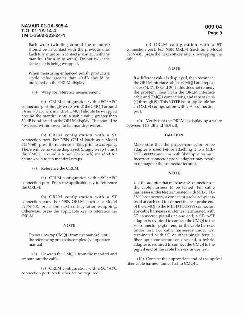
009 04Page 9
NAVAIR 01-1A-505-4T.O. 01-1A-14-4TM 1-1500-323-24-4
Each wrap (winding around the mandrel)should be in contact with the previous one.Each turn must be in contact in contact with themandrel (for a snug wrap). Do not twist thecable as it is being wrapped.
When measuring enhanced polish products astable value greater than 40 dB should beindicated on the ORLM display.
(6) Wrap for reference measurement.
(a) ORLM configuration with a SC/APCconnection port. Snugly wrap (wind) the CMQJ1 arounda 6 mm (0.25 inch) mandrel. CMQJ1 should be wrappedaround the mandrel until a stable value greater than30 dB is indicated on the ORLM display. This should beobserved within seven to ten mandrel wraps.
(b) ORLM configuration with a STconnection port. For NSN ORLM (such as a Model525N-60), press the reference softkey prior to wrapping.There will be no value displayed. Snugly wrap (wind)the CMQJ1 around a 6 mm (0.25 inch) mandrel forabout seven to ten mandrel wraps.
(7) Reference the ORLM.
(a) ORLM configuration with a SC/APCconnection port. Press the applicable key to referencethe ORLM.
(b) ORLM configuration with a STconnection port. For NSN ORLM (such as a Model525N-60), press the next softkey after wrapping.Otherwise, press the applicable key to reference theORLM.
NOTE
Do not unwrap CMQJ1 from the mandrel untilthe referencing process is complete (see operatormanual).
(8) Unwrap the CMQJ1 from the mandrel andsmooth out the cable.
(a) ORLM configuration with a SC/APCconnection port. No further action required.
(b) ORLM configuration with a STconnection port. For NSN ORLM (such as a Model525N-60), press the next softkey after unwrapping thecable.
NOTE
If a different value is displayed, then reconnectthe ORLM interface cable to CMQJ1 and repeatsteps (6), (7), (8) and (9). If this does not remedythe problem, then clean the ORLM interfacecable and CMQJ1 connections, and repeat steps(4) through (9). This NOTE is not applicable foran ORLM configuration with a ST connectionport.
(9) Verify that the ORLM is displaying a valuebetween 14.3 dB and 15.9 dB.
CAUTION
Make sure that the proper connector probeadapter is used before attaching it to a MIL-DTL-38999 connector with fiber optic termini.Incorrect connector probe adapter may resultin damage to the connector termini.
NOTE
Use the adapter that matches the connectors onthe cable harness to be tested. For cableharnesses under test terminated with MIL-DTL-38999 connectors, a connector probe adapter isused at each end to connect the test probe endof the CMQJ to the MIL-DTL-38999 connector.For cable harnesses under test terminated withST connector pigtails at one end, a ST-to-STadapter is required to connect the CMQJ to theST connector pigtail end of the cable harnessunder test. For cable harnesses under testterminated with SC or other single ferrule,fiber optic connectors on one end, a hybridadapter is required to connect the CMQJ to thepigtail end of the cable harness under test.
(10) Connect the appropriate end of the opticalfiber cable harness under test to CMQJ1.
009 04Page 10
NAVAIR 01-1A-505-4T.O. 01-1A-14-4TM 1-1500-323-24-4
(11) Select the applicable CMQJ2, and connectCMQJ2 to the other end of the optical fiber cable harnessunder test as shown in Figure 2.
NOTE
The CMQJ2 (or the appropriate single fibercable of CMQJ2) should be wrapped aroundthe mandrel until a stable value is indicated onthe ORLM display. Ten mandrel wraps areusually sufficient to obtain a stable value (i.e.,a value that varies within 1.0 dB).
(12) Wrap the CMQJ2 (or the appropriate singlefiber cable of CMQJ2) around a 6 mm (0.25 inch) mandrel.
NOTE
The CMQJ2 (or the appropriate single fibercable of CMQJ2) should be wrapped aroundthe mandrel until a stable value is indicated onthe ORLM display. Ten mandrel wraps areusually sufficient to obtain a stable value.
(13) Record the value displayed by the ORLM.
NOTE
Do not unwrap CMQJ2 from the mandrel untilthe return loss value has been recorded.
(14) Unwrap CMQJ2 from the mandrel andsmooth out the cable.
NOTE
If the optical fiber cable harness under test isterminated with single fiber connectors on theinput side, disconnect CMQJ2 from the cableharness under test. Repeat steps (9) through(15) for the other fibers in the optical fiber cableharness under test.
If the optical fiber cable harness under test isterminated with multi-fiber connectors on theinput side, disconnect the optical fiber cableharness under test and the ORLM interfacecable from CMQJ1. Repeat steps (5) through(15) for the other fibers in the optical fiber cableharness under test.
(15) Repeat the test for each fiber in the opticalfiber cable harness.
(16) Repeat this measurement for each fiber atthe other end of the cable harness, if specified in thePlatform manual.
(17) Once testing is completed, secure testequipment. Install protective caps (dust covers) over allCMQJs, cable harness connectors and test equipmentports.
Figure 2. ORLM Cable Harness Measurement Setup (Typical)

009 04Page 11
NAVAIR 01-1A-505-4T.O. 01-1A-14-4TM 1-1500-323-24-4
c. Acceptance of Optical Return Loss.
NOTE
The optical fiber cable assembly is consideredacceptable if the measured return loss is greaterthan or equal to the minimum specified cableharness return loss. If the measured return lossis acceptable, proceed to step (3) below. If themeasured return loss is less than the minimumcable harness return loss, proceed to step (2)below.
(1) Verify the measured return loss is largerthan the specified value in the Platform manual.
(2) If the return loss value is not acceptable (i.e.,larger than the specified value), disconnect and cleanall the connections and retest. If the measured cableharness return loss is still unacceptable, re-polish theoptical fiber cable harness terminations or replace thedefective components and retest.
(3) If the optical fiber cable harness is not goingto be immediately connected to its mating connectors,install protective caps over the optical fiber cableassembly connectors.
Page 11/12 (Blank)

009 04Page 12
NAVAIR 01-1A-505-4T.O. 01-1A-14-4TM 1-1500-323-24-4
THIS PAGE LEFT INTENTIONALLY BLANK

009 05Page 1
NAVAIR 01-1A-505-4T.O. 01-1A-14-4TM 1-1500-323-24-4
Fault Location Isolation Method Using OTDR
Reference Material
Definitions ............................................................................................................................. WP 003 01Safety .................................................................................................................................... WP 004 01Handling Practices ................................................................................................................. WP 006 01Inspection .............................................................................................................................. WP 008 01Manual Cleaning Procedures ................................................................................................. WP 008 02
Alphabetical Index
Subject Page No.
Fault Location Isolation Method Using OTDR ..................................................................................... 5Finding the Group Index ................................................................................................................ 6Safety Summary ............................................................................................................................ 6Test for Fiber Break and Cable Spool Attenuation ......................................................................... 9Test Setup ..................................................................................................................................... 7
Introduction .......................................................................................................................................... 5
Record of Applicable Technical Directives
None
13 August 2004

009 05Page 2
NAVAIR 01-1A-505-4T.O. 01-1A-14-4TM 1-1500-323-24-4
metI noitpircseD ytitnauQ edoCegaC .oNgniyfitnedIrotraP 4/
TNEMPIUQETSETRETEMOTCELFERNIAMODEMITLACITPO
JQMC )noitarugifnocreporptceles(steSrailucePnidnuofsepytJQMCrehtO:etoN
JQMCROTCENNOCCF
ezisrebifnorcim521/8.5edomelgniskcehcotesU 1 42360 5-38010OF
6CR80 80003OFK
ezisrebifnorcim521/5.7edomelgniskcehcotesU 1 42360 7-38010OF
ezisrebifnorcim521/9edomelgniskcehcotesU 1 42360 9-38010OF
6CR80 9003OFK
ezisrebifnorcim521/05edomitlumkcehcotesU 1 42360 05-93200OF
6CR80 01003OFK
ezisrebifnorcim521/5.26edomitlumkcehcotesU 1 42360 26-93200OF
6CR80 11003OFK
ezisrebifnorcim041/001edomitlumkcehcotesU 1 42360 001-93200OF
6CR80 21003OFK
JQMCEBORPTSET-OT-CF99983M
ezisrebifnorcim521/8.5edomelgniskcehcotesU 1 42360 5-09010OF
ezisrebifnorcim521/5.7edomelgniskcehcotesU 1 42360 7-09010OF
ezisrebifnorcim521/9edomelgniskcehcotesU 1 42360 9-09010OF
ezisrebifnorcim521/05edomitlumkcehcotesU 1 42360 05-24200OF
ezisrebifnorcim521/5.26edomitlumkcehcotesU 1 42360 26-24200OF
ezisrebifnorcim041/001edomitlumkcehcotesU 1 42360 001-24200OF
201E RDTOelbaevomerowttsaeltarofstols,noituloserdradnats,RDTOmumixamsehcni6x21x21,thgiewmumixambl51,seludom
derewopCAdnayrettab,tnirptoof1
A201E noitcennocTS,htgnelevawmn0551,edomelgnis,eludomRDTOmumixamretem51,egnarhtdiweslupmuminimsn001otsn5,trop
egnarcimanydmuminimBd52,enozdaednoitaunetta
1
B201E ,tropnoitcennocTS,htgnelevawmn058,edomitlum,eludomRDTOmuminimsn001otsn5,seziserocnorcim041/001otpurof
Bd02,enozdaednoitaunettamumixamretem5,egnarhtdiweslupegnarcimanydmuminim
1
)NOITARUGIFNOCREPORPTCELES(SRETPADAECNEREFER
301 retpadadirbyhTS-ot-CS 2
401 retpadadirbyhCF-ot-CS 2
501 retpadadirbyhTS-ot-CF 2
Support Equipment Required 1/, 2/

009 05Page 3
NAVAIR 01-1A-505-4T.O. 01-1A-14-4TM 1-1500-323-24-4
Support Equipment Required 1/, 2/ (cont.)
metI noitpircseD ytitnauQ edoCegaC .oNgniyfitnedIrotraP 4/
)D'TNOC(TNEMPIUQETSETRETEMOTCELFERNIAMODEMITLACITPO
)D'TNOC()NOITARUGIFNOCREPORPTCELES(SRETPADAECNEREFER
801 eborptset-ot-eborptset99983M 1 42360 C340-081
A801 mm52.1otmm5.2,eveelstnemngiladeppetS 1 42360 730-780
B801 hcni5260.0otmm5.2,eveelstnemngiladeppetS 1 42360 630-780
C801 hcni5260.0otmm52.1,eveelstnemngiladeppetS 1 42360 530-780
SRETPADAEBORPROTCENNOC 3/
SRETPADAEBORPROTCENNOC99983MNOMMOC
811 P2-P11-3M-1282167.ongwd,P2-P11-3M 1 42360 P2-11-60FN440-081
911 N-S2-R11-3M-1282167.ongwd,N-S2-R11-3M 1 42360 S2-11-70FN440-081
021 P4-P31-3M-1282167.ongwd,P4-P31-3M 1 42360 P4-31-60FN440-081
121 N-S4-R31-3M-1282167.ongwd,N-S4-R31-3M 1 42360 S4-31-70FN440-081
221 P5-P51-3M-1282167.ongwd,P5-P51-3M 1 42360 P5-51-60FN440-081
321 N-S5-R51-3M-1282167.ongwd,N-S5-R51-3M 1 42360 S5-51-70FN440-081
421 P8-P71-3M-1282167.ongwd,P8-P71-3M 1 42360 P8-71-60FN440-081
521 N-S8-R71-3M-1282167.ongwd,N-S8-R71-3M 1 42360 S8-71-70FN440-081
621 P11-P91-3M-1282167.ongwd,P11-P91-3M 1 42360 P11-91-60FN370-081
721 N-S11-R91-3M-1282167.ongwd,N-S11-R91-3M 1 42360 S11-91-70FN370-081
821 P73-P52-3M-1282167.ongwd,P73-P52-3M.onmetisihthtiwdedulcnierasretpadaowT:etoN
1 42360 PA73-52-60FN370-081PB73-52-60FN370-081
921 N-S73-R52-3M-1282167.ongwd,N-S73-R52-3M.onmetisihthtiwdedulcnierasretpadaowT:etoN
1 42360 SA73-52-70FN370-081SA73-52-70FN370-081
SRETPADAEBORPROTCENNOC99983MCIFICEPSTFARCRIA/MARGORPTNERRUC
702 A-S8-P71-3M-1282167.ongwd,A-S8-P71-3M 1 42360 S8-71-60FN440-081
802 A-P8-R71-3M-1282167.ongwd,A-P8-R71-3M 1 42360 AP8-71-70FN440-081
902 P61-P12-3M-1282167.ongwd,P61-P12-3M 1 42360 P61-12-60FN270-081
012 P45-P32-3M-1282167.ongwd,P45-P32-3M 1 42360 P45-32-60FN370-081
112 N-S45-R32-3M-1282167.ongwd,N-S45-R32-3M 1 42360 S45-32-70FN370-081
212 N-P45-R32-3M-1282167.ongwd,N-P45-R32-3M 1 42360 P45-32-00FN370-081
312 C-S92-R52-3M-1282167.ongwd,C-S92-R52-3M 1 42360 CS92-52-70FN440-081
412 P34-P52-3M-1282167.ongwd,P34-P52-3M 1 42360 P34-52-60FN440-081
512 N-S34-R52-3M-1282167.ongwd,N-S34-R52-3M 1 42360 S34-52-70FN440-081

009 05Page 4
NAVAIR 01-1A-505-4T.O. 01-1A-14-4TM 1-1500-323-24-4
Support Equipment Required 1/, 2/ (cont.)metI noitpircseD ytitnauQ edoCegaC .oNgniyfitnedIrotraP 4/
)EPYTEMASEHTFOSROTCENNOCELURREFELGNIS2ETAM(,ELURREFELGNIS,SRETPADA
10ATS dezidegguR,STOC,edomelgnis,retpadaTS-ot-TS 1
20ATS dezideggur,STOC,norcim521,edomitlum,retpadaTS-ot-TS 1
10ACS xelpmis,STOC,edomelgnis,retpadaCS-ot-CS 1
20ACS xelpmis,STOC,norcim521,edomitlum,retpadaCS-ot-CS 1
10ACL xelpud,STOC,edomelgnis,retpadaCL-ot-CL 1
20ACL xelpud,STOC,edomitlum,retpadaCL-ot-CL 1
SLOOTLATNEMELPPUS
SROTCENNOC99983MNIINIMRETEVOMER&TRESNIOTSLOOT
141 )citsalp(5/&4/40592Mroflootnoitcartxe&noitresnI 3 94318 30-41/96918M
241 )latem(5/&4/40592MlootnoitresnI 1 94318 702-8/96918M
341 )latem(5/&4/40592MlootnoitcartxE 1 94318 802-8/96918M
441 TS,retpadarebiferaB 1
541 edibrac,citporebif,)ebircs(revaelcneP0634914100115NSN
1
ECNEREFERYBDEDULCNITNEMPIUQETROPPUS
)20800PW(gninaelCdnaHlaunaMdna)10800PW(noitcepsnIroftnempiuqEtroppuSeeS
1/ tseTkniLlacitpO,tfarcriA,citpOrebiF,teStseT,2282167gniwarDAESVANrepdeificepsesohteraelbatsihtnismetIrepdeificepsesohteraelbatsihtnisretpadaecnereferdnasretpadaeborprotcennoc,JQMCehT.seirosseccA&tnempiuqEotsnoisiverynA.citpOrebiF,tnempiuqEtsetroF,)JQMC(srepmuJytilauQtnemerusaeMSTOC,1282167gniwarDAESVAN
.sgniwardesehtrofssecorpecnatpecca3.1.8.4RIAVANehthguorhtdevorppaeradnanidnuofeblliwsmetieseht
2/ noitcepsnigninaelcdnemmoceR.emulovsihtnigninaelCrednudetsileragninaelcrotcennocroftnempiuqenoitcepsnI.spiteborpnoitcepsnielbacilppahtiw)SIVOF(metsySnoitcepsnIoediVcitpOrebiFasedulcnitnempiuqe
3/ :)rotcennoc99983-LTD-LIMehthtiwesurof(snoitangisedretpadaeborprotcennoC:swollofsaera)N-S2-R11-3Msahcus(noitpircsednisnoitangiseD
piteborprotcennocehthtiwelbitapmocrotcennocinimretelpitlumfoepyT=3M)elcatpecer=R,gulp=P(epytydobdnaezisllehsretpadaeborprotcennoC=R11)tekcos=S,nip=P(ytivactresnirofepytinimretdnaseitivactresniforebmuN=S2
epytgulP.ylnosretpadaeborpepytelcatpecerrof,elbacilppaeraFhguorhtAosla,lamron=N(noitisopgniyek=N.)selcatpecer99983Mdeyekynatifnacsretpadaeborprotcennoc
4/ .metiehtrofstnemeriuqerllufehtteemotdeifitnedineebevahtahtstcudorp'srerutcafunamroferadetsilsrebmuntraPdenimretedebotytilibacilppA.tesehtgnittiftuorofstcudorptnelaviuqeecudorpotemoclewerasrerutcafunamrehtO
.ssecorpylppuselbacilppaehthguorht
009 05Page 5
NAVAIR 01-1A-505-4T.O. 01-1A-14-4TM 1-1500-323-24-4
Materials Required
Cleaning consumable supplies only. Cleaning suppliesare listed under Manual Cleaning Procedures in thisvolume (see WP 008 02).
1. INTRODUCTION.
2. This work package provides a general methodfor verifying the acceptability of a cable spool prior tosectioning/cutting the spool into individual lengths toconstruct a cable harness. One procedure is to find thefiber length and verify it is the same length as markedon the cable spool. A shorter length found is an indicationof finding a break in an optical fiber. A second procedureis to observe the attenuation trace along the length ofthe spooled cable. A step decrease in attenuation is anindication of spliced cable or a pinch/imperfection(unacceptable features to start cable construction). Asteep slope in the attenuation (high attenuation alongthe fiber length) is also unacceptable. This methodrequires the use of an Optical Time DomainReflectometer (OTDR). The trace of reflection andattenuation over the length of the optical fiber is used toidentify the existence and location of breaks or points ofhigh attenuation. For accurate attenuationmeasurements, an optical source and power metershould be used. The OTDR used for this measurementhas a standard resolution. A future WP will be developedfor finding the location of a break in a short length ofcable (such as a cable harness). This task requires theuse of a different type OTDR having much finerresolution (high resolution OTDR).
3. Fault Location Isolation Method Using OTDR.
WARNING
DO NOT stare into the end of an optical fiberconnected to an LED or laser diode. Light maynot be visible but can still damage the eye.
CAUTION
Inspect, clean (if needed) and re-inspect aftercleaning a connector/terminus ferrule andmating instrument adapters/interfacesimmediately before each mating to ensureaccurate and reproducible results. Perform theinspection and cleaning per WP 008 02.
NOTE
The number one cause for an increased opticalloss, after an insufficiently tight connection, isdirt and film deposits. No single cleaningmethod has been found to date that willguarantee a clean end face on the ferrule.Magnified visual inspection together withcleaning is important, when practical. Visualinspection is done using a FOVIS.Recommended cleaning supplies are listed inWP 008 02.
Inspection of an instrument interface/opticalsource transmit port. To inspect an opticaltransmit port, an adapter (such as an ST adapter)must be installed on the instrument interfaceport. The FOVIS ST inspection “tip” will easilymate to this. The image of a ferrule end face,from a fiber pigtail connected to a LD or LED,will be observed on the FOVIS. Surroundingthe fiber core and cladding, an image of theoptical port backing/mounting panel will beobserved. This mounting panel may be metal,not ceramic. As a result, more roughenedsurface features may be mistaken as dirt/particles. Inspection and cleaning, using themethods specified in WP 008 02, may be used asthe discriminator to differentiate dirt and filmdeposits from roughened surface imperfections.The latter can be identified by being unchangedafter cleaning and appearing only outside thefiber surface.

009 05Page 6
NAVAIR 01-1A-505-4T.O. 01-1A-14-4TM 1-1500-323-24-4
Inspection of an instrument interface/opticalreceiver port. To inspect an optical receiverport, an adapter (such as an ST adapter) mustbe installed on the instrument interface port.The FOVIS ST inspection “tip” will easily mateto this. There is a photodetector behind theoptical connection port on an optical powermeter or the Rx port on an OLTS (optical losstest set). The image of this large photodetectorwill be displayed by the FOVIS. No image willbe viewed of a ferrule end with a fiber in thecenter. Adjust the FOVIS focus until somedistinguishable features on the photodetectorsurface or the surrounding surface are observed.Dirt or film deposits on the photodetectorsurface may now be seen. Surrounding thephotodetector, some of the optical port backing/mounting panel may be observed. Thismounting panel may be metal, not ceramic. Asa result, a more roughened surface featuresmay be mistaken as dirt/particles. Inspectionand cleaning, using the methods specified inWP 008 02, may be used as the discriminator todifferentiate dirt and film deposits fromroughened surface imperfections. The lattercan be identified by being unchanged aftercleaning and appearing only outside thephotodetector surface.
Ensure the test equipment calibration is current.
During handling, all cables shall be protectedfrom kinks, twists, crushing, and sharp bends(see Handling Practices WP 006 01).
CMQJs wear out. CMQJs must be maintainedby inspection and cleaning per WP 008 01 andWP 008 02. CMQJs must be replaced when theyperform poorly after proper inspection andcleaning per WP 008 01 and WP 008 02.
Connector adapters accumulate dirt. Connectoradapters must be maintained by inspectionand cleaning per WP 008 01 and WP 008 02.
CMQJ(s) used must be compatible withapplicable requirements specified in thePlatform maintenance manual for fiber sizeand ferrule end face polish. Only like polishtypes (PC/PC, APC/APC or NC/NC) shouldbe mated together.
Test probe CMQJ insertion and removal iscovered in WP 009 07.
The OTDR must be compatible with applicablerequirements (such as operating wavelength)specified in Platform maintenance manual forthe cables being tested. These requirementsinclude compatibility with wavelength, fibertype (multimode or single-mode) and fibercore size.
a. Safety Summary. The safety precautions inWP 004 01 shall be observed. The following safetyprecautions are restated for emphasis:
(1) Do not touch the ends of the fiber as theymay be razor sharp. Wash your hands before and afterhandling bare fiber.
(2) Do not stare into the end of a fiber untilverifying that the fiber is not connected to a laser lightsource or LED.
b. Finding the Group Index.
(1) Following the OTDR manufacturer’sinstructions, energize the OTDR.
(2) Enter the group index of the cable to test.
(a) If the group index of the cable is known,then enter the group index.
1 Refer to the Platform manual for theproper group index.
2 Next proceed to the test setup.

009 05Page 7
NAVAIR 01-1A-505-4T.O. 01-1A-14-4TM 1-1500-323-24-4
(b) If the group index of the cable is notknown, do the following:
CAUTION
Inspect, clean (if needed) and re-inspect aftercleaning a connector/terminus ferrule andmating instrument adapters/interfacesimmediately before each mating to ensureaccurate and reproducible results. Perform theinspection and cleaning per WP 008 02.
NOTE
The number one cause for an increased opticalloss, after an insufficiently tight connection, isdirt and film deposits. No single cleaningmethod has been found to date that willguarantee a clean end face on the ferrule.Magnified visual inspection together withcleaning is important, when practical. Visualinspection is done using a FOVIS.Recommended cleaning supplies are listed inWP 008 02.
1 Connect a spool of cable in whichthe cable length has been verified (calibrated cablelength) to the OTDR, in accordance with the OTDRmanufacturer’s instructions.
2 Enter the required parameters,except the cable group index, in accordance with theOTDR manufacturer’s instructions
3 Adjust and place the cursor at thebeginning of the trace to obtain the distance coordinatez1 (see Figure 1).
4 Place the second cursor at the end ofthe trace to obtain the distance coordinate z2 (seeFigure 1).
5 Adjust the group index setting untilthe difference (z2-z1) equals the length of the calibratedcable length.
(3) Disconnect the calibrated cable length fromthe OTDR.
c. Test Setup.
CAUTION
Inspect, clean (if needed) and re-inspect aftercleaning a connector/terminus ferrule andmating instrument adapters/interfacesimmediately before each mating to ensureaccurate and reproducible results. Perform theinspection and cleaning per WP 008 02.
NOTE
The number one cause for an increased opticalloss, after an insufficiently tight connection, isdirt and film deposits. No single cleaningmethod has been found to date that willguarantee a clean end face on the ferrule.Magnified visual inspection together withcleaning is important, when practical. Visualinspection is done using a FOVIS.Recommended cleaning supplies are listed inWP 008 02.
Figure 1. OTDR Display (Typical)

009 05Page 8
NAVAIR 01-1A-505-4T.O. 01-1A-14-4TM 1-1500-323-24-4
NOTE
This setup is to observe distance and attenuationfor verifying and that there are no breaks/kinks in a spool of fiber optic cable.
If the correct configuration CMQJ is availablewith a FC connector on one end, then theFC-to-ST jumper is not required. Proceed tostep (3) and substitute the words “FC connector”for “ST connector” on one end of CMQJ1.Figure 2 shows the test setup for theconfiguration without the additional FC-to-STjumper.
The CMQJ or the alternative FC-to-ST jumpermay also be referred to as a low loss, dead zonecable. The CMQJ or alternative jumper shouldhave a minimum length of 10 meters (up to50 meters on older OTDR models) to distinguishthe reflection at the OTDR optical interfaceport from the connection of the dead zone cable(CMQJ) to cable spool under test. For purposesof verifying that there are no breaks or kinksand attenuation is not excessive, the 2 meterlength CMQJ is sufficient. The reflections at theOTDR and at the CMQJ-to-test cable interfaceswill appear as one large reflective pulse (asopposed to two pulses shown in Figure 3).
(1) Connect a ST-to-ST adapter to the STconnector end of the FC-to-ST jumper.
(2) Select the applicable CMQJ for CMQJ1.
NOTE
Use the adapter that matches the connectors onthe CMQJ. For a CMQJ terminated with SC orother single ferrule, fiber optic connectors onone end, a hybrid adapter is required to connectthe CMQJ to the bare fiber adapter on the cablespool under test.
For unterminated cable ends, use the ST-to-STCMQJ connected to a bare fiber adapter toconnect to unterminated cable ends. For ferrulehole diameter sizes that may not becommercially available (such as for a nominal140, 155 or 172 micron diameter), use a terminusor connector with the correct ferrule holediameter as a bare fiber adapter.
(3) Connect the end of the fiber cable spoolunder test to CMQJ1 using the appropriate adapter.
NOTE
This procedure was developed from EIA/TIA-455-61 (FOCP-61) "Measurement of Fiberor Cable Attenuation Using an OTDR".
Figure 2. Test Setup

009 05Page 9
NAVAIR 01-1A-505-4T.O. 01-1A-14-4TM 1-1500-323-24-4
Figure 3. OTDR Display (Typical)
d. Test for Fiber Break and Cable Spool Attenuation.
(1) Verify Distance. Adjust and place the cursorat the beginning (z1) and the end (z2) of the trace for thecable spool under test (see Figure 3). Record the cablespool length (z2 - z1) and confirm that the measuredlength matches the length that is recorded on the cablespool.
NOTE
Any sudden drop off of the attenuation trace,before the end of the cable harness, indicates abreak in the fiber.
The first part of the trace shown in Figure 3corresponds to the CMQJ and the second partcorresponds to the cable spool under test. Sincea 2 meter CMQJ is used, the reflections at theOTDR and at the CMQJ-to-cable spool interfaceswill appear as one large reflective pulse (asopposed to the first two pulses shown inFigure 3).
A length that is less than that of the spool ofcable indicates a break in the fiber.
(2) Verify no kinks and large optical losses.Adjust and place the cursor at the beginning (z3) andend (z4) of the linear portion of the trace for the channelunder test (see Figure 3). Record the cable attenuationin dB, (P3) and (P4) at these two positions. The OTDRmay automatically calculate the cable attenuation. If itdoes not, calculate the attenuation (B) in dB/km usingthe equation B=(P3-P4)/(z4-z3).
NOTE
A step change in attenuation trace along thefiber is an indication of kinks or splices in thespool of cable. Both kinks and splices are notacceptable. Reject the cable.
Page 9/10 (Blank)
Generally, the loss of a cable is determinedwith optical loss tools (see WP 009 01). With theOTDR, if the maximum measured attenuationfor a fiber exceeds the fiber’s attenuation perlength specification by more than 1 dB/km, thecable may have been damaged. Verification ofsuspected damage should be performed withoptical loss tools (see WP 009 01). If theattenuation along the cable in dB/km exceedsthe maximum allowed cable attenuation bymore than 3 dB/km, redo the CMQJ-to-cablespool interface. When bare fibers or splices areused at this interface, poor cleaves will causehigh optical losses.
(3) The cable spool under test is consideredsatisfactory if there are no breaks in the fiber.
(4) Once testing is completed, secure testequipment. Install protective caps (dust covers) over allCMQJs, cable harness connectors and test equipmentports.

009 05Page 10
NAVAIR 01-1A-505-4T.O. 01-1A-14-4TM 1-1500-323-24-4
THIS PAGE LEFT INTENTIONALLY BLANK

009 06Page 1
NAVAIR 01-1A-505-4T.O. 01-1A-14-4TM 1-1500-323-24-4
Fault Location Isolation Method Using Fault Finder
Reference Material
Definitions ............................................................................................................................. WP 003 01Safety .................................................................................................................................... WP 004 01Handling ................................................................................................................................ WP 006 01Troubleshooting Strategy ....................................................................................................... WP 007 01Inspection .............................................................................................................................. WP 008 01Manual Cleaning Procedures ................................................................................................ WP 008 02
Alphabetical Index
Subject Page No.
Fault Location Isolation Method Using Fault Finder ............................................................................. 2Procedure ...................................................................................................................................... 3Safety Summary ............................................................................................................................ 3
Introduction .......................................................................................................................................... 2
Record of Applicable Technical Directives
None
Support Equipment Required 1/
13 August 2004
metI noitpircseD ytitnauQ edoCegaC .oNgniyfitnedIrotraP 2/
611 )ecafretnimm5.2/w(redniFtluaFlausiV 1
ECNEREFERYBDEDULCNITNEMPIUQETROPPUS
)20800PW(gninaelClaunaMdna)10800PW(noitcepsnIroftnempiuqEtroppuSeeS
1/ tnempiuqEtseTkniLlacitpO,tfarcriA,citpOrebiF,teStseT,2282167gniwarDAESVANrepdeificepstahtsielbatsihtnimetIecnatpecca3.1.8.4RIAVANehthguorhtdevorppaeradnanidnuofeblliwsmetiesehtotsnoisiverynA.seirosseccA&
.gniwardsihtrofssecorp
2/ .metiehtrofstnemeriuqerllufehtteemotdeifitnedineebevahtahtstcudorp'srerutcafunamroferadetsilsrebmuntraPdenimretedebotytilibacilppA.tesehtgnittiftuorofstcudorptnelaviuqeecudorpotemoclewerasrerutcafunamrehtO
.ssecorpylppuselbacilppaehthguorht
009 06Page 2
NAVAIR 01-1A-505-4T.O. 01-1A-14-4TM 1-1500-323-24-4
Materials Required
Cleaning consumable supplies only. Cleaning suppliesare listed under Manual Cleaning Procedures in thisvolume (see WP 008 02).
1. INTRODUCTION.
2. This work package (WP) is a visual inspectiontroubleshooting method to determine if there is a breakin the fiber. A light source in the range of visible light isused. If a fiber break is present, the visible light is seenthrough the outer jacket at the break, but not at the farend. One limitation with this method is that it is onlyeffective when one of the two cases occurs. The first caseis when there is a break and visible light can be seen atthe break through the outer jacket. The second case iswhen there is a break and no light is visible at the farend. The operator must be aware that visible light maybe seen through the outer jackets of some cables, but notothers. Also, sufficient light may be transmitted througha hairline crack to be observed at the outer end. One canconclude there is a break, only if visible light may beseen through the outer jacket. One cannot concludethere is no break, when some light is seen at the outputend. The fault finder cannot be used to conclude thereis no break. Optical loss tools (see WP 009 01) are usedto determine when a fiber optic cable is not at fault.Optical loss tools should be used to determine if testingwith a fault finder is appropriate.
3. Fault Location Isolation Method Using FaultFinder.
WARNING
DO NOT stare into the end of an optical fiberconnected to an LED or laser diode. Light maynot be visible but can still damage the eye.
The fault finder is a Class III-A visable lasersource. The user is responsible for followingmanufacturer operating instructions regardingsafe operation. Specifically, the user is requiredto “contain" the beam at all times, even at theexit of a cable under test.
CAUTION
Inspect, clean (if needed) and re-inspect aftercleaning a connector/terminus ferrule andmating instrument adapters/interfacesimmediately before each mating to ensureaccurate and reproducible results. Perform theinspection and cleaning per WP 008 02.
NOTE
The number one cause for an increased opticalloss, after an insufficiently tight connection, isdirt and film deposits. No single cleaningmethod has been found to date that willguarantee a clean end face on the ferrule.Magnified visual inspection together withcleaning is important, when practical. Visualinspection is done using a FOVIS.Recommended cleaning supplies are listed inWP 008 02.
NOTE
Inspection of an instrument interface/opticalsource transmit port. To inspect an opticaltransmit port, an adapter (such as an ST adapter)must be installed on the instrument interfaceport. The FOVIS ST inspection “tip" will easilymate to this. The image of a ferrule end face,from a fiber pigtail connected to a LD or LED,will be observed on the FOVIS. Surroundingthe fiber core and cladding, an image of theoptical port backing/mounting panel will beobserved. This mounting panel may be metal,not ceramic. As a result, more roughenedsurface features may be mistaken as dirt/particles. Inspection and cleaning, using themethods specified in WP 008 02, may be used asthe discriminator to differentiate dirt and filmdeposits from roughened surface imperfections.The latter can be identified by being unchangedafter cleaning and appearing only outside thefiber surface.

009 06Page 3
NAVAIR 01-1A-505-4T.O. 01-1A-14-4TM 1-1500-323-24-4
Inspection of an instrument interface/opticalreceiver port. To inspect an optical receiverport, an adapter (such as an ST adapter) mustbe installed on the instrument interface port.The FOVIS ST inspection “tip" will easily mateto this. There is a photodetector behind theoptical connection port on an optical powermeter or the Rx port on an OLTS (optical losstest set). The image of this large photodetectorwill be displayed by the FOVIS. No image willbe viewed of a ferrule end with a fiber in thecenter. Adjust the FOVIS focus until somedistinguishable features on the photodetectorsurface or the surrounding surface are observed.Dirt or film deposits on the photodetectorsurface may now be seen. Surrounding thephotodetector, some of the optical port backing/mounting panel may be observed. Thismounting panel may be metal, not ceramic. Asa result, a more roughened surface featuresmay be mistaken as dirt/particles. Inspectionand cleaning, using the methods specified inWP 008 02, may be used as the discriminator todifferentiate dirt and film deposits fromroughened surface imperfections. The lattercan be identified by being unchanged aftercleaning and appearing only outside thephotodetector surface.
During handling, all cables shall be protectedfrom kinks, twists, crushing, and sharp bends(see Handling Practices WP 006 01).
CMQJs wear out. CMQJs must be maintainedby inspection and cleaning per WP 008 01 andWP 008 02. CMQJs must be replaced when theyperform poorly after proper inspection andcleaning per WP 008 01 and WP 008 02.
Connector adapters accumulate dirt. Connectoradapters must be maintained by inspectionand cleaning per WP 008 01 and WP 008 02.
a. Safety Summary. The safety precautions inWP 004 01 shall be observed. The following safetyprecautions are restated for emphasis:
(1) Do not touch the ends of the fiber as theymay be razor sharp. Wash your hands before and afterhandling bare fiber.
(2) Do not stare into the end of a fiber untilverifying that the fiber is not connected to a laser lightsource or LED.
b. Procedure.
CAUTION
Inspect, clean (if needed) and re-inspect aftercleaning a connector/terminus ferrule andmating instrument adapters/interfacesimmediately before each mating to ensureaccurate and reproducible results. Perform theinspection and cleaning per WP 008 02.
NOTE
The number one cause for an increased opticalloss, after an insufficiently tight connection, isdirt and film deposits. No single cleaningmethod has been found to date that willguarantee a clean end face on the ferrule.Magnified visual inspection together withcleaning is important, when practical. Visualinspection is done using a FOVIS.Recommended cleaning supplies are listed inWP 008 02.
NOTE
If the cable harness is terminated on one end,select the terminated end.
(1) Select one end of the cable harness undertest.

009 06Page 4
NAVAIR 01-1A-505-4T.O. 01-1A-14-4TM 1-1500-323-24-4
NOTE
Different types of CMQJs may be used in thisprocedure. CMQJ selection is provided basedon the type of connector on the cable harness.For testing a cable harness with a MIL-DTL-38999 connector, the ST-to-Test probe CMQJ isused. For testing a cable harness with a STconnector, a ST-to-ST CMQJ is used for the endof the cable harness. For testing a cable harnesswith other types of single ferrule connectors, aST-to-applicable single ferrule connector CMQJis used for the end the cable harness with theapplicable single ferrule connector pigtail.
CMQJ(s) used must be compatible withapplicable requirements specified in thePlatform maintenance manual for fiber sizeand ferrule end face polish. Only like polishtypes (PC/PC or NC/NC) should be matedtogether.
Test probe CMQJ insertion and removal iscovered in WP 009 07.
(2) Select the applicable CMQJ.
CAUTION
Make sure that the proper connector probeadapter is used before attaching it to a MIL-DTL-38999 connector with fiber optic termini.Incorrect connector probe adapter may resultin damage to the connector termini.
Figure 1. Fault Finder, Light Leakage Through Cable Jacket
NOTE
Use the adapter that matches the connectors onthe cable harness to be tested. For cableharnesses under test terminated with MIL-DTL-38999 connectors, a connector probe adapter isused at each end to connect the test probe endof the CMQJ to the MIL-DTL-38999 connector.For cable harnesses under test terminated withST connector pigtails at one end, a ST-to-STadapter is required to connect the CMQJ to theST connector pigtail end of the cable harnessunder test. For cable harnesses under testterminated with SC or other single ferrule,fiber optic connectors on one end, a hybridadapter is required to connect the CMQJ to thepigtail end of the cable harness under test.
If the ends of the cable are not terminated witha connector, then use the ST-to-ST CMQJconnected to a bare fiber adapter to connect tounterminated cable ends.
(3) Connect the appropriate end of the cableharness under test to the CMQJ1 using the appropriateadapter (see Figure 1).
(4) Connect the ST connector end of CMQJ1 tothe fault finder adapter port.

009 06Page 5
NAVAIR 01-1A-505-4T.O. 01-1A-14-4TM 1-1500-323-24-4
Figure 2. Fault Finder, Light LeakageThrough Cable Jacket
NOTE
The visable output of the fault finder from thecable under test must be contained. Do notstare directly into the opposite end of the fiber.Use a white card or some other means to verifylight is present. One alternative approach is toinspect for light by viewing the fiber from theside instead of from the edge. If this approachis used and no light is seen, then use a whitecard to verify the absence of light.
Light may be visible at the opposite end and thefiber could still be cracked or otherwise partiallybroken.
If no light is seen, verify that the fault finder isturned to the "ON" position and is generatingvisible light output, before inspecting the cablejacket for leaks.
If no light is seen, verify that any intermediateconnectors are properly tightened, beforeinspecting the cable jacket for leaks.
Fault finders usually have a "blinking" modethat may enhance detection of visable lightleakage through the fiber cable’s outer jacket(and possible over-braiding).
Cable over-braiding, inaccessible cable sectionsand bright ambient background conditionsseverely limit the use of the fault finder indetecting and locating fiber breaks.
(5) Turn the fault finder to the "ON" position.
(6) Test Conclusions.
(a) Fiber Breakage Conclusion. A fiberbreak can be concluded if visable fault finder light isseen leaking through the cable outer jacket. See Figure 2.
1 When a fiber break has beenconclusively found, the accurate location (within +/- 1inch of a cable end) of the break must be documented sothat a repair can be initiated. See WP 012 and WP 013.
(b) Fiber Break Suspected. A fiber breakcan only be strongly suspected if no light is seen at theoutput end of the cable under test and there are nointermediate connectors. In this case all connectionsshould be inspected and cleaned (WP 008 02), then thecable must be closely examined for leakage through thecable outer jacket. If leakage through the cable outerjacket cannot be determined, then OTDR tools (WP 00905) must be used.
(c) No Breakage Conclusion. The faultfinder cannot be used to conclude there is no break.Optical loss tools (WP 009 01) are used to determinewhen a fiber optic cable is not at fault.
(d) Inconclusive. All other conditionsobserved with the fault finder are inconclusive evidence.
(e) Multiple Fiber Breaks. Only the first orfirst and second of multiple fiber breaks may beobserved.
(9) Once testing is completed, secure testequipment. Install protective caps (dust covers) over allCMQJs, cable harness connectors and test equipmentports.
Page 5/6 (Blank)

009 06Page 6
NAVAIR 01-1A-505-4T.O. 01-1A-14-4TM 1-1500-323-24-4
THIS PAGE LEFT INTENTIONALLY BLANK

009 07Page 1
NAVAIR 01-1A-505-4T.O. 01-1A-14-4TM 1-1500-323-24-4
Test Probe CMQJ Insertion and Removal
Reference Material
None
Alphabetical Index
Subject Page No.
Introduction .......................................................................................................................................... 2Test probe Insertion and Removal ......................................................................................................... 2
Test Probe Insertion ....................................................................................................................... 2Test Probe Removal ...................................................................................................................... 2
Record of Applicable Technical Directives
None
Support Equipment Required
None
Material Required
None
13 August 2004

009 07Page 2
NAVAIR 01-1A-505-4T.O. 01-1A-14-4TM 1-1500-323-24-4
1. INTRODUCTION.
2. This work package is the method to be used bypersonnel for inserting and removing the test probeend of a CMQJ to and from a connector probe adapter.The test probe CMQJ is used with a connector probeadapter for testing a multiple termini connector.
3. TEST PROBE INSERTION AND REMOVAL.
a. Test Probe Insertion.
(1) Insert a test probe end of a CMQJ into aconnector probe adapter by gripping the knurled area(knurled insert body) firmly between your thumb andindex finger (see Figure 1 and Figure 2).
(2) While holding the test probe by the knurledinsert body, press the test probe into the selected cavityon the connector probe adapter until a click is heard orfull engagement is felt (see Figure 2). This click indicatesthat the spring is fully loaded and the retention clip isengaged.
b. Test Probe Removal.
(1) Remove or extract a test probe from aconnector probe adapter by pushing the removal body(extended flange) on the test probe into the connectorprobe adapter until the retention clip is disengaged (seeFigure 3). Position tip of thumb and finger on externalflange while pad of the thumb and index finger is on theknurled insert body.
(2) Maintain the hold on the removal body(extended flange) depressed towards the connectorprobe adapter while holding the pad of the thumb andindex finger is on the knurled insert body. Pull the testprobe out of the connector probe adapter (see Figure 4).
Figure 2. Grip Knurled Insert Body andPress Into Cavity
Figure 1. Parts of the Test Probe
Figure 3. To Extract, Push ExtendedFlange Towards Connector
Figure 4. Extract While Maintaining Hold onExtended Flange

010 00Page 1
NAVAIR 01-1A-505-4T.O. 01-1A-14-4TM 1-1500-323-24-4
Connector Terminations
Reference Material
Definitions ............................................................................................................................. WP 003 01Safety .................................................................................................................................... WP 004 01HAZMAT ............................................................................................................................. WP 004 02Manual Cleaning Procedures ................................................................................................. WP 008 02
Alphabetical Index
None
LIST OF SUBORDINATE WORK PACKAGES
SUBORDINATESUBJECT WORK PACKAGE DATETermination Process Overview with Associated Risks 010 01 13 August 2004
Record of Applicable Technical Directives
None
13 August 2004
1. POLICY, CURRENT, FIBER OPTICTERMINATION. There are no approved and verified,common fiber optic connector termination proceduresfor aircraft (fixed wing and rotary) applications. Seespecific Platform maintenance plan for cablereplacement guidance.
2. RISK OF TERMINATING WITHOUTAPPROVED PROCEDURES. It is critical that fiber opticconnector ferrule end faces meet all specified surface
topology criteria required by the specific Platform.Without approved and verified fiber optic terminationprocedures, required fiber optic end face surfacetopology criteria cannot be accurately, repeatedly andreliably produced. Use of other than approvedterminating procedures can result in the mating ofincompatible fiber optic end faces. The mating ofincompatible end faces can result in degradedperformance of fiber optic connectors.
Page 1/2 (Blank)

010 00Page 2
NAVAIR 01-1A-505-4T.O. 01-1A-14-4TM 1-1500-323-24-4
THIS PAGE LEFT INTENTIONALLY BLANK

010 01Page 1
NAVAIR 01-1A-505-4T.O. 01-1A-14-4TM 1-1500-323-24-4
Termination Process Overview with Associated Risks
Reference Material
None
Alphabetical Index
Subject Page No.
Introduction .......................................................................................................................................... 2Termination Process Overview with Associated Risks .......................................................................... 2
Crimp Cable Strength Member ...................................................................................................... 3Cure Epoxy ................................................................................................................................... 3Cut and Strip ................................................................................................................................. 2Inspection ...................................................................................................................................... 4Mix Epoxy and Inject into Connector ............................................................................................ 2Polishing ....................................................................................................................................... 4
Record of Applicable Technical Directives
None
Support Equipment Required
None
Materials Required
None
13 August 2004

010 01Page 2
NAVAIR 01-1A-505-4T.O. 01-1A-14-4TM 1-1500-323-24-4
1. INTRODUCTION.
CAUTION
This guidance is not to be used in lieu of aspecific procedure.
2. This work package provides general guidanceon major steps in performing terminations along withthe associated risks.
3. TERMINATION PROCESS OVERVIEW WITHASSOCIATED RISKS.
a. Cut and Strip. A typical fiber optic cable (simplexcable) consists of an outer jacket, strength member(such as aramid yarn or woven fiberglass), and the fiberbuffer / coating. These must be carefully cut back andstripped in the termination process. This operationrequires the use of cable cutting and buffer strippingtools. Risks associated with the cut and strip operationsare as follows:
(1) Strip Cable Jacket. Correct tools and correcttechnique when using the proper tools must beemployed. Otherwise, penetration of the outer cablejacket (nicks, cuts, etc.) or fiber breakage may occur . Forinstance, pushing off the simplex cable jacket with atightly held simplex cable stripper can lead to fiberbreakage.
(2) Cable Length. Tolerance on cable length istight when building a harness with multiple fiber cables.For instance, the tolerance on the overall length of acable harness may be +13/-0 mm (+0.5/-0.0 in) with atolerance on each cable in the harness of +7/-0 mm(+0.25/-0.0 in). Violating the tolerance places excessivetensile loading on some of the terminations, leading tobreakage.
(3) Strip Length. Strip dimensions must beaccurate. Incorrect lengths may allow the internal fiberto be unsupported and exposed within the ferrule. Thismay lead to greater optical attenuation or fiber cracking.
(4) Strip Buffer. Proper technique must be usedwhen stripping off the buffer using a mechanicalstripper. Removal of the buffer from the optical fiber
may lead to scoring of the glass when improper tools orwhen correct tools with improper technique is used.Most buffer materials must be removed in 6 mm (0.25inch) segments. Other buffer materials (such as silicone)may be removed in one section. Polyimide coating onpolyimide coated optical fiber is not removed. Onceexposed, bare, uncoated optical fiber (i.e., the opticalfiber with the buffer removed) is in its most vulnerablestate from the point of buffer removal until thetermination process is completed.
(5) Clean Optical Fiber. The exposed opticalfiber is cleaned to remove residual buffer scrapings andany dirt acquired during the stripping operation. Theoptical fiber is wiped from the cable jacket out to thefiber end. Repeated wiping is not done. This can weakenthe fiber.
(6) Cut Strength Member Yarn. Cutting of thestrength member (such as Kevlar or woven fiber glass)must be done so that an even cut is obtained. Specialscissors are required to ensure a complete and clean cut.Otherwise, protruding strands may interfere withconnector/terminus retention mechanisms.
b. Mix Epoxy and Inject into Connector. Thissequence involves precise mixing of a two-part epoxyand injecting it into the barrel of the connector / terminuswith a syringe. Epoxy must be carefully mixed andinjected to avoid a structurally weak and/or opticallylossy termination. The operations of this sequenceinvolve subtle technicalities that can significantly affectperformance, quality and reliability. Some of theseoperations are:
(1) Preliminary Operation.
(a) Ferrule Hole Inspection. The ferrulehole must be free of dirt/debris or the fiber will not fitthrough the ferrule hole. The fiber will easily break if itis forced. A quick visual inspection is sufficient withcorrective action taken when light is not visible fromthe back of the connector/terminus.
(b) Dry Fit Fiber. This is done when ferruleswith tight hole tolerances are specified. Connectors/termini with several different ferrule hole diametersmust be kept on hand. An operation to dry fit the

010 01Page 3
NAVAIR 01-1A-505-4T.O. 01-1A-14-4TM 1-1500-323-24-4
connector/terminus onto each fiber length must bedone (starting with the size for with smallest ferrulehole diameter and working up) to ensure proper ferrulehole clearance before the injection of epoxy. Potentialfor fiber breakage is increased with the performance ofthis operation.
(c) Prevent Epoxy Wicking. Epoxy wickingmust be avoided. Less viscous epoxies may wick downthe strength member yarn (such as Kevlar or wovenfiber glass) and into the unexposed length of the cableunderneath the simplex cable jacket. Potential for fiberbreakage is increased as the hardened epoxy preventsfiber movement within the cable jacket. An extremetransition is created where the fiber is more prone to beplaced in an unacceptably sharp bend. Measures can betaken to prevent wicking.
(2) Mix Epoxy. Specified quantities of each partof a two part epoxy must be mixed together for theepoxy to exhibit the required performance properties.Epoxy in premixed packets are used to ensure thecorrect mixture percentages are obtained. Epoxy has alimited shelf life so care must be taken to ensure that ithas not expired. Techniques for mixing the epoxy mustinclude measures to minimize the introduction of airbubbles while obtaining a uniform mixture. Air bubblesin cured epoxy can lead to higher fiber optical loss,intermittent performance and the potential for fiberbreakage.
(3) Inject Epoxy.
(a) Quantity. A syringe is used to inject asufficient, but not excessive, amount of epoxy into theconnector/terminus. Some connectors/termini requirea special syringe tip configuration to ensure a completefill is obtained. An insufficient quantity can leaveexposed bare or buffered fiber, whereas an excessiveamount may interfere with mechanical functions. Excessepoxy may cause adherence to cure adapters, makingconnector/terminus removal form cure adaptersdifficult after completion of curing step.
(b) Epoxy Bead Size. Epoxy applicationmust ensure a small epoxy bead exists to secure thefiber at the ferrule tip. Improper bead size may impedethe termination process. Too large an epoxy bead on the
ferrule end face will result in excess polishing time,expenditure of additional consumable materials andplacing deeper scratches in the fiber. Too small (orcomplete lack of) a bead may potentially result in fiberbreakage.
c. Crimp Cable Strength Member. Some connector/terminus configurations require crimping of the strainrelief (such as strength member yarn) of fiber opticcable onto the connector / terminus. The use of theproper crimp tools and dies is essential to obtain theproper cable reinforcement without damaging the fiber.
(1) Die Size. Proper crimp tool die size must beused. Otherwise, potential exists for loss of barrelintegrity (resulting in fiber breakage) or reducedstrength of cable strain relief capture mechanism(resulting in connector/terminus separation from thecable).
(2) Crimp Technique. Proper crimp techniquemust be employed for mechanical fit (no “fins” producedin crimp), sufficient strain relief retention, and forminimizing of any cable strain relief protrusion fromthe crimp sleeve (no mechanical seating/interfaceproblems).
(3) Heat Shrink/Heat Gun. Heat shrink may beused to cover the strength member yarn, to transitiondown to the desired finish diameter and to providestrain relief (prevent sharp bends) at the boundarybetween connector and cable. (Epoxy is used to securethe fiber in the connector/terminus and to secure thestrength member yarn onto the outside or inside of theconnector/terminus barrel when a crimp sleeve is notused.) A heat gun is used to reduce the diameter of theheat shrink. The potential to overheat the cable existswith use of the heat gun. Other general usage restrictionswith heat guns apply, such as the avoidance of usagearound fuels and other combustible materials.
d. Cure Epoxy. Cure epoxy to secure the opticalfiber to the ferrule at a specified cure cycle (schedule).This operation requires the use of specified curing ovenand connector/terminus holding fixtures. The cureschedule is optimized to give the most desired set ofepoxy properties for the intended aircraft environment.

010 01Page 4
NAVAIR 01-1A-505-4T.O. 01-1A-14-4TM 1-1500-323-24-4
(1) Epoxy Cure Schedule. The time andtemperature (or times and temperatures if a multiplestep cure is required) in which a specified epoxy iscured must be followed to obtain the requiredperformance properties. Otherwise, an insufficient curemay result in degraded optical performance (due tofiber movement) or reduced cable strain relief.
(2) Handling Technique. Improper placementin curing oven or in curing adapters may result in anincomplete cure. Improper placement of cabling exitingfrom connectors/termini may result in epoxypenetrating and then hardening on the cable jacket.
(3) Overheating. Improper cure schedule usedcan result in overheating and degrading of cableassembly materials (primarily the optical fiber bufferand the cabling components).
e. Polishing. This process polishes the ferrule endface of a connector/terminus to obtain the requiredoptical loss and return loss. This step is the one whichdetermines the geometry (surface topology) of theferrule end face. The method/procedure employedmust be one that will provide consistent results withacceptable optical performance and end face geometry.This operation requires the use of specialized polishingpads, pucks and plates to rough polish through to finepolish the ferrule end face. Different polishingtechniques result in different finishes for the ferrule endface.
(1) Cleave Excess Fiber Stub. Proper techniquemust be used to cleave the protruding length of fiberfrom the ferrule. Otherwise, potential for shattering ofthe fiber at the ferrule end face can result.
(2) Polishing Paper Selection. Too small of agrit size paper may result in excessive polishing time.Too large of a grit size paper may place permanent,large scratches in the fiber.
(3) Polishing Puck. Use of specified polishingpuck (tool) is required for obtaining end face geometry(surface topology) requirements consistently andefficiently.
(4) Polishing Procedure. Using a verifiedpolishing procedure provides consistent results. This ismandatory to obtain specified Platform opticalperformance requirements (optical loss, return loss)and end face geometry. Otherwise, use of differenttools, consumable materials and techniques will usuallyproduce terminations that look good, but have degradedoptical performance and unacceptable end facegeometries. When polishing pucks, polishing paper,etc. are used properly in accordance with the specifiedconnector termination procedure, connector end facegeometries with optical loss and return loss (singlemode only) values, as specified in the componentspecifications, will be obtained.
f. Inspection. Inspection of the ferrule end faceoccurs during and after the polishing step. During thepolishing step, a ferrule end face inspection is performedafter each operation in which a different polishingpaper is used.
(1) Inspection Type. Visual, magnified (200xminimum) inspections are performed using a FiberOptic Video Inspection System (FOVIS), during andafter the polishing operation. The inspection is done toverify the optical surface is smooth and free of scratches,pits, chips and fractures. As an option, an eye safe lightsource, may be used to illuminate the opposite end ofthe fiber for better core visibility.
(2) Inspection Limitations. Inspections arelimited to two dimensional visual examinations of theferrule end face. These inspections are done under 400Xmagnification for terminations (200X for inspectionand cleaning during mating operations). Theseinspections provide only a partial, two-dimensionalrepresentation to assess acceptability. A properly donetermination negates the need to perform optical lossand end face geometry measurements to completelyassess acceptance of the termination.
011 00Page 1
NAVAIR 01-1A-505-4T.O. 01-1A-14-4TM 1-1500-323-24-4
Cable Harness Assembly
Reference Material
None
Alphabetical Index
None
LIST OF SUBORDINATE WORK PACKAGES
SUBORDINATESUBJECT WORK PACKAGE DATEM38999 Cable Harness Assembly 011 01 13 August 2004
Record of Applicable Technical Directives
None
13 August 2004
NOTE
There is no one method for assembly of a fiberoptic cable harness for aircraft (fixed wing androtary) applications. This work packagecontains general guidance. See the platformmaintenance manual for the assembly of aspecific cable harness.
1. INTRODUCTION.
2. This work package (WP) is divided intosubordinate work packages for different types ofassembly methods to build cable harnesses. The firstsubordinate work package, WP 0011 01, addresses anassembly method to build up simplex fiber optic cablesinto a cable harness configured with MIL-DTL-38999Series III connectors and convoluted tubing. Futuresubordinate work packages are planned to addressother configurations.
Page 1/2 (Blank)

011 00Page 2
NAVAIR 01-1A-505-4T.O. 01-1A-14-4TM 1-1500-323-24-4
THIS PAGE LEFT INTENTIONALLY BLANK

011 01Page 1
NAVAIR 01-1A-505-4T.O. 01-1A-14-4TM 1-1500-323-24-4
M38999 Cable Harness Assembly
Reference Material
Definitions ............................................................................................................................. WP 003 01Safety .................................................................................................................................... WP 004 01General Handling Practices .................................................................................................... WP 006 01
Alphabetical Index
Subject Page No.
Assembly (Build Up) of M38999 Cable Harness .................................................................................. 2Inserting Fiber Optic Cable Assemblies Into the Convoluted Tubing ............................................. 3Preparing Terminated Fiber Optic Cable Assemblies for Inclusion Into Convoluted Tubing .......... 2
Introduction .......................................................................................................................................... 2
Record of Applicable Technical Directives
None
Support Equipment Required
None
Materials Required
None
13 August 2004
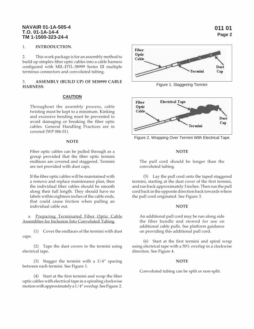
011 01Page 2
NAVAIR 01-1A-505-4T.O. 01-1A-14-4TM 1-1500-323-24-4
1. INTRODUCTION.
2. This work package is for an assembly method tobuild up simplex fiber optic cables into a cable harnessconfigured with MIL-DTL-38999 Series III multipleterminus connectors and convoluted tubing.
3. ASSEMBLY (BUILD UP) OF M38999 CABLEHARNESS.
CAUTION
Throughout the assembly process, cabletwisting must be kept to a minimum. Kinkingand excessive bending must be prevented toavoid damaging or breaking the fiber opticcables. General Handling Practices are incovered (WP 006 01).
NOTE
Fiber optic cables can be pulled through as agroup provided that the fiber optic terminiendfaces are covered and staggered. Terminiare not provided with dust caps.
If the fiber optic cables will be maintained witha remove and replace maintenance plan, thenthe individual fiber cables should be smoothalong their full length. They should have nolabels within eighteen inches of the cable ends,that could cause friction when pulling anindividual cable out.
a. Preparing Terminated Fiber Optic CableAssemblies for Inclusion Into Convoluted Tubing.
(1) Cover the endfaces of the termini with dustcaps.
(2) Tape the dust covers to the termini usingelectrical tape.
(3) Stagger the termini with a 3/4” spacingbetween each termini. See Figure 1.
(4) Start at the first termini and wrap the fiberoptic cables with electrical tape in a spiraling clockwisemotion with approximately a 1/4” overlap. See Figure 2.
NOTE
The pull cord should be longer than theconvoluted tubing.
(5) Lay the pull cord onto the taped staggeredtermini, starting at the dust cover of the first termini,and run back approximately 3 inches. Then run the pullcord back in the opposite direction back towards wherethe pull cord originated. See Figure 3.
NOTE
An additional pull cord may be run along sidethe fiber bundle and stowed for use onadditional cable pulls. See platform guidanceon providing this additional pull cord.
(6) Start at the first termini and spiral wrapusing electrical tape with a 50% overlap in a clockwisedirection. See Figure 4.
NOTE
Convoluted tubing can be split or non-split.
Figure 1. Staggering Termini
Figure 2. Wrapping Over Termini With Electrical Tape

011 01Page 3
NAVAIR 01-1A-505-4T.O. 01-1A-14-4TM 1-1500-323-24-4
CAUTION
Do not push fiber optic cables throughconvoluted tubing as the fiber optic cables cansnag and be severely damaged.
b. Inserting Fiber Optic Cable Assemblies Into theConvoluted Tubing.
(1) Feed Pull Cord into Convoluted Tubing.
(a) Short Lengths. Feed the free end of thepull cord into the unmarked end of the convolutedtubing.
(b) Long Lengths. Longer runs ofconvoluted tubing with complex bends will require aleader. Make a leader out of a flannel or other soft clothpatch attached to a string long enough to pass completelythrough the convoluted tubing. The patch should fitloosely in convoluted tubing (See Figure 5). Usecompressed air at no more than 35 psi to blow patch andattached string through the convoluted tubing. (Avacuum source from the exit side also works well, butbe careful not to allow the patch to be pulled in thevacuum device.)
(2) Install the compression nut from the adapteronto the marked end of the convoluted tubing. Ensurethat the threads are orientated towards the marked endof the convoluted tubing.
(3) Feed the free end of the pull cord, into theunmarked end of the convoluted tubing.
(4) Route the free end of the pull cord until itexits out the opposite marked end of the convolutedtubing.
(5) While pulling on the free end of the pullcord, carefully start guiding the taped bundled fiberoptic cable assemblies into the unmarked end of theconvoluted tubing. Continue to gently pull the bundledfiber optic cable assemblies until they exit out themarked end of the convoluted tubing.
Figure 3. Placement of Pull Cord
Figure 4. Attaching Pull Cord Using Electrical Tape
Figure 5. Leader for Convoluted Tubing

011 01Page 4
NAVAIR 01-1A-505-4T.O. 01-1A-14-4TM 1-1500-323-24-4
CAUTION
Take your time when untaping the fiber optic cableassemblies. Severe damage can result to the termini.
(6) Carefully untape the bundled fiber opticcable assemblies and remove the dust caps from thetermini.
(7) Inspect the fiber optic cable assemblies forany damage. The inspection should include assessmentwith optical loss (link loss) and visual fault finder tools.If damage is found, then repairs will be needed.
CAUTION
Severe damage (fiber breakage) is likely, ifinsertion tool(s) are not used to insert the terminiinto the connector cavities.
(8) Slide the adapter housing over all of thetermini before inserting the termini into the M38999
connector. Use the appropriate Platform maintenancemanual for guidance to insert the termini into thedesignated cavities. Insertion tool(s) shall be used toinsert termini in all cases.
(9) Fit the split bushing, from the adapter, overthe convoluted tubing. Carefully slide the adapterhousing up and over the split bushing with the capturedconvoluted tubing.
(10) Thread the adapter housing onto the rear ofthe M38999 connector. Ensure that the split bushingstill has the convoluted tubing captured while threadingthe adapter housing onto the M38999 connector.
(11) Thread the compression nut onto the rear ofthe adapter housing and torque to 40 +/- 5 inch pounds.
012 00Page 1
NAVAIR 01-1A-505-4T.O. 01-1A-14-4TM 1-1500-323-24-4
Cable Harness Installation
Reference Material
None
Alphabetical Index
None
LIST OF SUBORDINATE WORK PACKAGES
SUBORDINATESUBJECT WORK PACKAGE DATEGeneral Practices for Cable Harness Installation 012 01 13 August 2004
Record of Applicable Technical Directives
None
13 August 2004
1. INTRODUCTION.
2. This work package (WP) is divided intosubordinate work packages for different types ofinstallation guidance with cable harnesses. The firstsubordinate work package, WP 012 01, addressesgeneral guidance for installing a cable harness. Futurework packages are planned to address uniquetechniques to be used for specific configurations.
3. READY FOR INSTALLATION (RFI) POLICY.The following action must be performed and criterionmet for any new installation, replacement or repair of afiber optic cable component or cable assembly (includingcable, cable bundle, cable harness and connector):
a. Performance of an optical loss test procedureper WP 009 01.
b. Verification that the cable assembly installed orcontaining the item repaired meets the Platformmaximum acceptable optical loss for that cable assembly.
Page 1/2 (Blank)

012 00Page 2
NAVAIR 01-1A-505-4T.O. 01-1A-14-4TM 1-1500-323-24-4
THIS PAGE LEFT INTENTIONALLY BLANK

012 01Page 1
NAVAIR 01-1A-505-4T.O. 01-1A-14-4TM 1-1500-323-24-4
General Practices for Cable Harness Installation
Reference Material
Definitions ............................................................................................................................. WP 003 01Safety .................................................................................................................................... WP 004 01Manual Cleaning Procedures ................................................................................................. WP 008 02
Alphabetical Index
Subject Page No.
Installation of Fiber Optic Cable and Cable Assemblies ........................................................................ 2Cable Bend Diameter Considerations ............................................................................................ 6Cable Primary Support .................................................................................................................. 2Cable Pulls Do s and Don ts .......................................................................................................... 15Cable Secondary Support .............................................................................................................. 5Connector Coupling ...................................................................................................................... 11Protecting Cables and Cable Assemblies From Chafing ................................................................ 6Routing Practices ........................................................................................................................... 14Safety Summary ............................................................................................................................ 2Special Protective Measures While Routing .................................................................................. 13Transporting .................................................................................................................................. 16Types of Protection Over Cable ..................................................................................................... 13
Introduction .......................................................................................................................................... 2
Record of Applicable Technical Directives
None
Support Equipment Required
None
Materials Required
Clamp, Cushioned Metal MS21919Tape, Finish C, Glass Tying, Size 2 A-A-52083Tape, Finish C, Glass Tying, Size 3 A-A-52083Tape, Finish C, Polyester Tying, Size 2 A-A-52081Tape, Finish C, Polyester Tying, Size 3 A-A-52081
13 August 2004

012 01Page 2
NAVAIR 01-1A-505-4T.O. 01-1A-14-4TM 1-1500-323-24-4
1. INTRODUCTION.
2. This work package provides general guidancefor installing a cable harness. The guidance includescable bend diameter considerations, types of protectionover cable, special protective measures while routing,routing practices, cable pull do’s and don’ts, primarysupport, secondary support, connector couplingguidelines, and transporting cable harnesses. Whenavailable, maintenance personnel should always lookfirst to the aircraft maintenance manual for guidance.The information provided herein should not be usedfor design or modification on the optical cabling. Designand modifications should be performed in accordancewith SAE–AS50881.
a. The materials and components used in the designof aircraft are intended to meet strict performance,reliability, and safety requirements. Replacement ofany component or material with a substitute must beapproved in advance by the applicable Platform Office.
3. INSTALLATION OF FIBER OPTIC CABLEAND CABLE ASSEMBLIES.
a. Safety Summary. The safety precautions inWP 004 01 shall be observed. The following safetyprecautions are restated for emphasis:
(1) Safety glasses shall be worn at all timeswhen handling bare fibers or dispensing epoxy.
(2) Do not touch the ends of the fiber, as theymay be razor sharp. Wash your hands before and afterhandling bare fiber.
(3) Avoid skin contact with epoxies.
(4) Do not stare into the end of a fiber untilverifying that the fiber is not connected to a laser lightsource or LED.
b. Cable Primary Support.
(1) Primary Support. Primary support of fiberoptic cable and cable assemblies shall be provided bymetal cushion clamps in accordance with MS21919.
(a) Plastic cable clamps SHALL NOT beused for the primary support of fiber optic cable orcable assemblies.
(b) Lacing Tape SHALL NOT be used forthe primary support of fiber optic cable or fiber opticcable assemblies.
(c) Plastic Cable Straps SHALL NOT beused for the primary support of fiber optic cable or fiberoptic cable assemblies.
(2) MS21919 Part Number. An example of aMS21919 part number is as follows:
(a) Example: MS21919 WDG-8.
(b) MS21919: Basic specification describingthe clamps.
(c) W: Indicates the base of the open end ofthe loop has a wedge to assist locking the clamp together(See Figure 1). Applicable for sizes 2 through 48 only.
(d) D: Defines the band material (SeeTable 1).
(e) G: Defines the cushion material (SeeTable 1).
(f) -8: Defines the cable thickness, whichthe band can hold (See Table 2).
(3) Clamp Replacements. When engineeringdrawings, mainframe manuals, etc. specify the canceledpart numbers as shown in Table 3 and 4, replace theclamp as indicated.
(4) Clamp Size And Restrictions. If a clampneeds to be replaced and is not specified by the aircraftmaintenance manual, use a MS21919 WCJ-* for sizes -2through -48 and MS21919 CJ-* for sizes -50 through -66.
(a) Clamp shall be installed such that theydo not exert more pressure on the cable than theminimum required to prevent slipping.
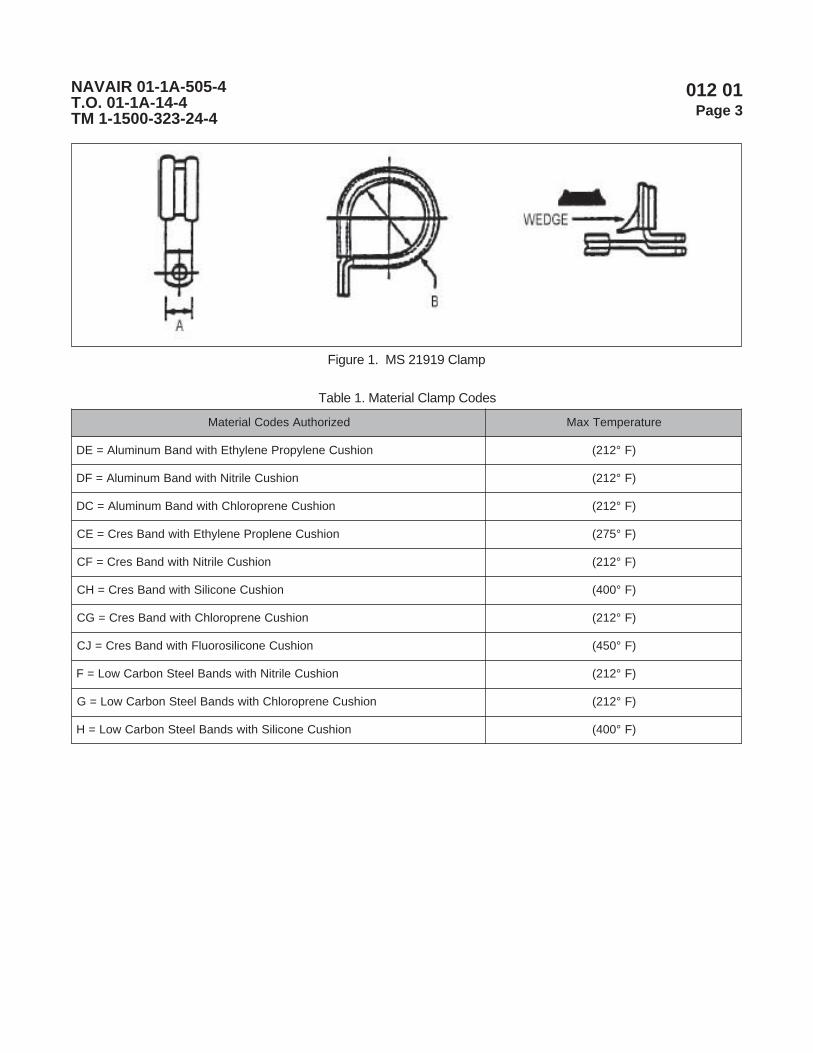
012 01Page 3
NAVAIR 01-1A-505-4T.O. 01-1A-14-4TM 1-1500-323-24-4
Figure 1. MS 21919 Clamp
dezirohtuAsedoClairetaM erutarepmeTxaM
noihsuCenelyporPenelyhtEhtiwdnaBmunimulA=ED )F°212(
noihsuCelirtiNhtiwdnaBmunimulA=FD )F°212(
noihsuCenerporolhChtiwdnaBmunimulA=CD )F°212(
noihsuCenelporPenelyhtEhtiwdnaBserC=EC )F°572(
noihsuCelirtiNhtiwdnaBserC=FC )F°212(
noihsuCenociliShtiwdnaBserC=HC )F°004(
noihsuCenerporolhChtiwdnaBserC=GC )F°212(
noihsuCenocilisoroulFhtiwdnaBserC=JC )F°054(
noihsuCelirtiNhtiwsdnaBleetSnobraCwoL=F )F°212(
noihsuCenerporolhChtiwsdnaBleetSnobraCwoL=G )F°212(
noihsuCenociliShtiwsdnaBleetSnobraCwoL=H )F°004(
Table 1. Material Clamp Codes

012 01Page 4
NAVAIR 01-1A-505-4T.O. 01-1A-14-4TM 1-1500-323-24-4
.oNhsaDpmalC ssenkcihTelbaC .oNhsaD ssenkcihTelbaC
1 61/1 72 8/51
2 8/1 82 4/3/1
3 61/3 92 4/31
4 4/1 03 8/71
5 61/5 13 8/71
6 8/3 23 0.2
7 61/7 33 0.2
8 2/1 43 8/12
9 61/9 53 8/12
01 8/5 63 4/12
11 61/11 73 4/12
21 4/3 83 8/32
31 61/31 04 2/12
41 8/7 24 2/12
51 61/51 34 2/12
61 1 44 4/32
71 61/11 54 4/32
81 8/11 64 4/32
91 61/31 84 0.3
02 4/11 05 0.3
12 61/51 25 4/13
22 8/31 45 4/13
32 61/71 65 2/13
42 2/l1 85 2/13
52 61/91 66 0.4
62 81/51 46 0.4
etoN.66hguorht12-sezisnielbaliavatonsi*F-18252SM1
66hguorht33-sezisnielbaliavatonsi*R-18252SM2
Table 2. Clamp Sizes

012 01Page 5
NAVAIR 01-1A-505-4T.O. 01-1A-14-4TM 1-1500-323-24-4
(b) The clamp shall not deform the cable sothat the optical performance characteristics aredegraded.
(5) Placement in Cable Clamps.
(a) Cable Installation. Pull through cableclamp. Do not push through a cable clamp. Preferenceis to open the cable clamp and lay the portion of thecable, cable bundle or cable harness into the cableclamp.
NOTE
If a cushioned clamp (clamp with rubberchannel or insert) is used, then no sliding shouldbe evident when a moderate force is applied.Tighten cable, conduit and convoluted tube toconstrain without constricting. This is to ensurethat no deformation, kink or pinch will occur.Tighten cable wrap until constriction isobserved, but no deformation, kink or pinch isevident.
(b) Tightening of cable clamp. Tighten cableclamps to the degree that the cable is snug, but to theextent that cable does not deform, kink or pinch. Ensurethat the cable, cable bundle or cable harness will slide inthe clamp when a moderate force is applied.
(6) Use of Rubber Channels. Use channel rubberwith banding straps where the latter is allowed
c. Cable Secondary Support.
(1) Lacing Types. The following tying typesmay be used to provide secondary support to fiberoptic cable or cable assemblies:
(a) For low vibration applications, usefinish C polyester tying tapes, size 2 or 3 in accordancewith A-A-52081.
(b) For medium or high vibrationapplications, use finish C, glass tying tapes, sizes 2 or 3in accordance with A-A-52083.
(2) General Precautions. When lacing or tyingfiber optic cables and cable assemblies, observe thefollowing precautions:
(a) Lace or tie bundles securely enough tosupport the cable or cable assemblies between primarysupports. Extreme care should be used in tying thelacing tape to assure that the tie does not deform thecable or cable assemblies.
rebmuNtraPdellecnaC rebmuNtraPtnemecalpeR
)()H,G,F(BW91912SM )()H,G,F(W91912SM
)()H,G,F(B91912SM )()H,G,F(W91912SM
)()G,F(D91912SM )()G,F(DW91912SM
)()H,G,F(C91912SM )()H,G,F(CW91912SM
)()H,G,F(91912SM )()H,G,F(W91912SM
)(HD91912SM )(HCW91912SM
)(HDW91912SM )(HCW91912SM
Table 3. Clamp Replacement for -2 through -48
rebmuNtraPdellecnaC rebmuNtraPtnemecalpeR
)()H,G,F(CW91912SM )()H,G,F(C91912SM
)()G,F(DW91912SM )()G,F(D91912SM
)()H,G,F(BW91912SM )()H,G,F(91912SM
)()H,G,F(B91912SM )()H,G,F(91912SM
)(HD91912SM )(HC91912SM
)(HDW91912SM )(HC91912SM
)()H,G,F(91912SM )()H,G,F(91912SM
Table 4. Clamp Replacement for -50 through-66
012 01Page 6
NAVAIR 01-1A-505-4T.O. 01-1A-14-4TM 1-1500-323-24-4
CAUTION
Applying lacing ties too tightly can lead todegraded optical performance or fiberbreakage. Use extreme caution when applyinglacing tape to assure that the ties do not deformthe cable or cable assembly.
(b) Do not use ties on the part of a cablegroup or bundle located inside a conduit.
(3) Continuous Lacing. Continuous lacing maynot be used for secondary support of fiber optic cable orcable assemblies.
(4) Plastic Cable Straps. Plastic Cable StrapsSHALL NOT be used for secondary support of fiberoptic cable or cable assemblies.
d. Cable Bend Diameter Considerations.
(1) Minimum Bend Diameter. The minimumbend diameter is the diameter at which a cable or cableharness can be bent without degrading opticalperformance or the diameter at which a loose tubecable, convoluted tube or conduit can be bent withoutkinking (tube collapse causing fiber breakage). Twotypes of minimum bend diameters, short-term andlong-term bend diameters, must be considered.
(2) Short-Term Bend Diameter. The short-termbend diameter applies during handling and installing.When the short-term bend diameter is not specified:
(a) Use a value of eight times the cablediameter for simplex, tight buffer cable (i.e., four timesthe cable diameter if working in terms of cable bendradius).
(b) Use a value of 20 times the cablediameter for simplex, loose tube cable (e.g., 2 mmdiameter loose tube cable results in a 40 mm cable benddiameter).
(c) Use a value of 20 times the tube diameterfor convoluted tube or conduit (e.g., 0.5 inch convolutedtubing results in a 10 inch cable bend diameter).
(3) Long-Term Bend Diameter. The long-termbend diameter applies to the completed installation.When the short-term bend diameter is not specified:
(a) Use a value of 16 times the cablediameter for simplex, tight buffer cable (i.e., eight timesthe cable diameter if working in terms of cable bendradius).
(b) Use a value of 20 times the cablediameter for simplex, loose tube cable.
(c) Use a value of 20 times the tube diameterfor convoluted tube or conduit.
e. Protecting Cables and Cable Assemblies FromChafing.
(1) Chafing. Chafing shall be prevented byrouting and clamping bundles to prevent contact withedges of equipment and structure. Where physicalseparation of at least 3/8-inch cannot be maintained,the edges shall be covered with suitable protectionstrips or grommets. Grommets and protection stripsshall be securely fastened in place. Grommets formaintenance usage and replacements are provided inTable 5. The grommets consist of two types: donut andcaterpillar.
(2) Donut Grommet Installation. Rubber(donut) grommets should be in accordance withMS35489. Donut grommets consist of rubber and areresistant to hot oils and coolants. The grommet has amaximum temperature application of 250°F. Anexample of the grommet is shown in Figure 2. Thegrommet should be replaced with an unsplit grommetwhenever possible. When grommet must be split, itshall be split as shown in Figure 3.
(a) MS35489 Part Number. An example ofthe part number using MS35489-14X is as follows:
1 MS35489: Basic and detailspecification number representing NASM3036 basicspecification and MS35489 detail specification for adonut grommet.

012 01Page 7
NAVAIR 01-1A-505-4T.O. 01-1A-14-4TM 1-1500-323-24-4
2 -14: Represent a specific sizegrommet for a particular hole size and edge thickness.
3 x: When present represents a siliconerubber. No letter represents a synthetic rubber.
(b) MS35489 Grommet Replacement. Whenan engineering drawing, maintenance manual, etc. orno information on the grommet is provided, use thesilicone rubber grommet (i.e. MS35489-14X).
(c) MS35489 Grommet Installation. Thegrommet should be installed as follows:
1 Measure the diameter of the holeand edge wall thickness.
2 Using the information provided inMS35489 specification, choose the correct silicone rubbergrommet.
3 Pressure inserts the grommet in thehole.
CAUTION
Do not damage the grommet.
4 If the grommet will not fit withoutapparent damage, cut the grommet as shown in Figure 3.
(3) Caterpillar Grommet Installation.Caterpillar grommets should be in accordance withNASM22529/2 and /3 detail specifications. The
Table 5. Caterpillar Grommet Replacement
-66212MSANetelosbO ).ni(ssenkcihTteehSstnemecalpeR
).ni(ssenkcihTteehS-2/92522M -3/92522M
1- 250.-510. 58-C1- 58-C1- 630.-520.
2- 580.-250. 58-C2- 58-C2- 360.-630.
3- 821.-580. 58-C3- 58-C3- 470.-950.
4- 291.-821. 58-C4- 90.-070.
5- 552.-291. 58-C5- 111.-090.
6- 813.-552. 58-C6- 431.-501.
7- 083.-813. 858-C7- 91.-871.
8- 015.-083. 58-C8- 062.-042.
A/N A/N *-C1- 630.-520.
A/N A/N *-C2- 360.-630.
A/N A/N *-C3- 470.-950.
A/N A/N *-C4- 390.-070.
A/N A/N *-C5- 111.-090.
A/N A/N *-C6- 431.-501.
A/N A/N *-C7- 891.-871.
A/N A/N *-C8- 062.-042.
SETONegdegnitnuomehtrof6elbaTnidetsilseltsacforebmunehtsetacidnI*
)4e3-10210hpargarap,PWsiht(,deriuqerhtgnelehtdna).cte,2-,1-(ssenkciht

012 01Page 8
NAVAIR 01-1A-505-4T.O. 01-1A-14-4TM 1-1500-323-24-4
Figure 2. Methods of Chafing Prevention
Figure 3. Lightening Hole Grommet Mounting
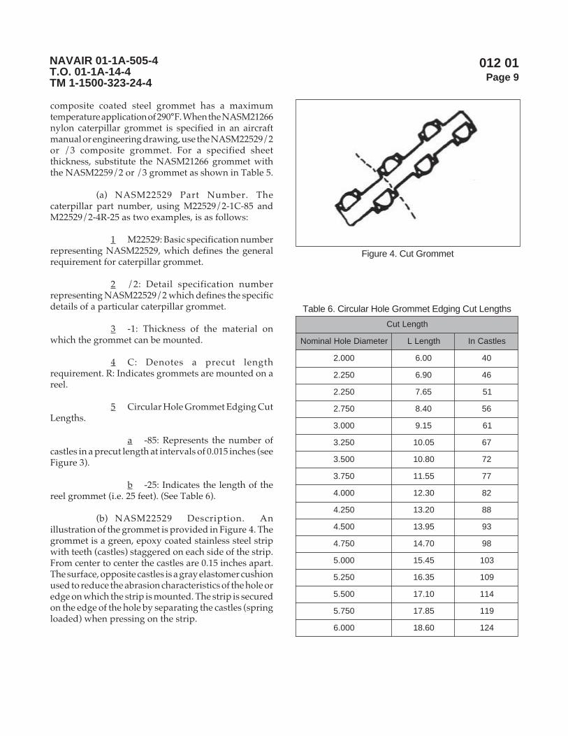
012 01Page 9
NAVAIR 01-1A-505-4T.O. 01-1A-14-4TM 1-1500-323-24-4
composite coated steel grommet has a maximumtemperature application of 290°F. When the NASM21266nylon caterpillar grommet is specified in an aircraftmanual or engineering drawing, use the NASM22529/2or /3 composite grommet. For a specified sheetthickness, substitute the NASM21266 grommet withthe NASM2259/2 or /3 grommet as shown in Table 5.
(a) NASM22529 Part Number. Thecaterpillar part number, using M22529/2-1C-85 andM22529/2-4R-25 as two examples, is as follows:
1 M22529: Basic specification numberrepresenting NASM22529, which defines the generalrequirement for caterpillar grommet.
2 /2: Detail specification numberrepresenting NASM22529/2 which defines the specificdetails of a particular caterpillar grommet.
3 -1: Thickness of the material onwhich the grommet can be mounted.
4 C: Denotes a precut lengthrequirement. R: Indicates grommets are mounted on areel.
5 Circular Hole Grommet Edging CutLengths.
a -85: Represents the number ofcastles in a precut length at intervals of 0.015 inches (seeFigure 3).
b -25: Indicates the length of thereel grommet (i.e. 25 feet). (See Table 6).
(b) NASM22529 Description. Anillustration of the grommet is provided in Figure 4. Thegrommet is a green, epoxy coated stainless steel stripwith teeth (castles) staggered on each side of the strip.From center to center the castles are 0.15 inches apart.The surface, opposite castles is a gray elastomer cushionused to reduce the abrasion characteristics of the hole oredge on which the strip is mounted. The strip is securedon the edge of the hole by separating the castles (springloaded) when pressing on the strip.
Figure 4. Cut Grommet
Table 6. Circular Hole Grommet Edging Cut Lengths
htgneLtuC
retemaiDeloHlanimoN htgneLL seltsaCnI
000.2 00.6 04
052.2 09.6 64
052.2 56.7 15
057.2 04.8 65
000.3 51.9 16
052.3 50.01 76
005.3 08.01 27
057.3 55.11 77
000.4 03.21 28
052.4 02.31 88
005.4 59.31 39
057.4 07.41 89
000.5 54.51 301
052.5 53.61 901
005.5 01.71 411
057.5 58.71 911
000.6 06.81 421
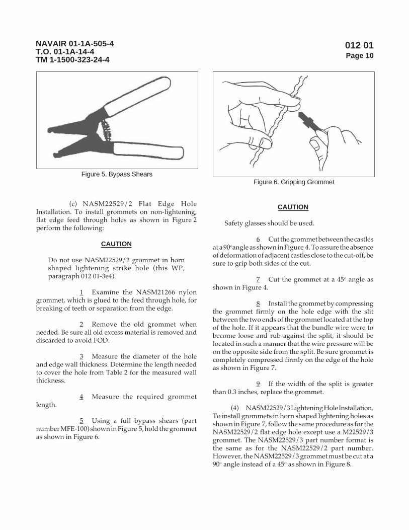
012 01Page 10
NAVAIR 01-1A-505-4T.O. 01-1A-14-4TM 1-1500-323-24-4
(c) NASM22529/2 Flat Edge HoleInstallation. To install grommets on non-lightening,flat edge feed through holes as shown in Figure 2perform the following:
CAUTION
Do not use NASM22529/2 grommet in hornshaped lightening strike hole (this WP,paragraph 012 01-3e4).
1 Examine the NASM21266 nylongrommet, which is glued to the feed through hole, forbreaking of teeth or separation from the edge.
2 Remove the old grommet whenneeded. Be sure all old excess material is removed anddiscarded to avoid FOD.
3 Measure the diameter of the holeand edge wall thickness. Determine the length neededto cover the hole from Table 2 for the measured wallthickness.
4 Measure the required grommetlength.
5 Using a full bypass shears (partnumber MFE-100) shown in Figure 5, hold the grommetas shown in Figure 6.
CAUTION
Safety glasses should be used.
6 Cut the grommet between the castlesat a 90oangle as shown in Figure 4. To assure the absenceof deformation of adjacent castles close to the cut-off, besure to grip both sides of the cut.
7 Cut the grommet at a 45o angle asshown in Figure 4.
8 Install the grommet by compressingthe grommet firmly on the hole edge with the slitbetween the two ends of the grommet located at the topof the hole. If it appears that the bundle wire were tobecome loose and rub against the split, it should belocated in such a manner that the wire pressure will beon the opposite side from the split. Be sure grommet iscompletely compressed firmly on the edge of the holeas shown in Figure 7.
9 If the width of the split is greaterthan 0.3 inches, replace the grommet.
(4) NASM22529/3 Lightening Hole Installation.To install grommets in horn shaped lightening holes asshown in Figure 7, follow the same procedure as for theNASM22529/2 flat edge hole except use a M22529/3grommet. The NASM22529/3 part number format isthe same as for the NASM22529/2 part number.However, the NASM22529/3 grommet must be cut at a90o angle instead of a 45o as shown in Figure 8.
Figure 6. Gripping GrommetFigure 5. Bypass Shears

012 01Page 11
NAVAIR 01-1A-505-4T.O. 01-1A-14-4TM 1-1500-323-24-4
f. Connector Coupling.
CAUTION
Do not use excessive force to mate plug toreceptacle.
(1) Connector Coupling: Assemble connectorto receptacle as follows:
(a) Inspect fiber optic termini forcleanliness using platform approved procedures andequipment prior to beginning mating. Appropriateinspection and cleaning practices are covered in WP008 01 and WP 008 02.
NOTE
Unmated connectors should be covered withappropriate caps (example, ESD caps, dust capsor bags) to prevent introduction of contaminatesonto the fiber optic termini end faces. Unmatedconnectors should not be covered with tape.
(b) Locate the proper position of the plugin relation to the receptacle by aligning the key of onepart with the groove or keyway of the other part.(Figure 2).
CAUTION
Do not twist bundle excessively to achieveproper mating of plug to receptacle.
Do not misconnect plug and receptacle byforcing pins into the resilient insert, either bymisalignment of properly mating connector orby joining connectors with identical shells butdifferently keyed insert arrangements.
(c) Start the plug into the receptacle with alight forward pressure and engage the threads ofcoupling ring and receptacle.
(d) Alternately push in the plug and tightenthe coupling ring until the plug is completely seated.
(e) When mating a connector with bayonetlock coupling, make sure that all locking rivets of thecoupling are engaged.
CAUTION
Be careful not to lock the plug while cocked,i.e., two locking rivets engaged and one notengaged.
Do not hammer a plug into its receptacle. Neveruse a torque wrench or pliers to lock couplingrings.
(f) For threaded connectors, make sure thefully mated indicator stripe on the receptacle is coveredby the coupling ring of the connector when viewnormally to the axis of the connector. (See Figure 9).
(g) A bayonet connector is fully matedwhen the connector-locking pin can be visually seen inthe inspection hole. (See Figure 9).
Figure 8. Drainage Hole in Low Point of Tubing or Tape
Figure 7. Lightening Hole Grommet Mounting

012 01Page 12
NAVAIR 01-1A-505-4T.O. 01-1A-14-4TM 1-1500-323-24-4
Figure 9. Mating or Coupling Connectors
012 01Page 13
NAVAIR 01-1A-505-4T.O. 01-1A-14-4TM 1-1500-323-24-4
g. Types of Protection Over Cable.
(1) Types of Protection. The following four typesof protection, over the cable or in which the cable isplaced, defined for this work package is as follows:
(a) Conduit. Metallic tube in whichindividual cable or cable bundles are placed.
(b) Non-Metallic Conduit. Convolutedtube or non-metallic straight tube in which individualcable or cable bundles are placed.
(c) Cable Wrap. Non-metallic, convolutedtube with one slit running along the length of the tube.Cable wrap is also referred to as split loom.
(d) Over-Braid. Metallic wire or non-metallic string woven into a web shape, tubularconfiguration.
(2) Guidance on Primary Use.
(a) Conduit. Pre-install in aircraft, then pullcable, cable bundle or cable harness through the conduit
1 Measure the bundle wires beforeinstalling in conduit. The bundle diameter must notexceed 80% of the internal diameter of the conduit.
(b) Non-Metallic Conduit. Convolutedtube is used during fabrication of a cable harness witha multiple termini connector (such as the M38999) onone or both ends. Non-metallic, straight tube is pre-install in aircraft; then the cable, cable bundle or cableharness is pulled through the conduit.
1 Measure the bundle wires beforeinstalling in conduit. The bundle diameter must notexceed 80% of the internal diameter of the conduit.
(c) Cable Wrap. Pre-install in aircraft; thenopen the slit and place cabling into the cable wrap.
(d) Over-Braid. Metallic wire or non-metallic overbraid is not placed directly on top of a fiberoptic cable or cable bundle.
(3) Guidance for tightening inside cable clamps.
(a) Conduit and Non-Metallic Conduit.Tighten to constrain without constricting. Constrictingthe conduit or non-metallic conduit will kink the tubestructure resulting in potential fiber breakage.
(b) Cable Wrap. Cable wrap may betightened to point of constriction since the constrictiondoes not create a hard point is which a kink will occur.
h. Special Protective Measures While Routing.
(1) Protection from Excessive Heat. Route fiberoptic cable, cable bundles or cable harness away fromhigh temperature equipment (engines, heat exchangers,exhaust stacks, heating ducts, de-icers, etc.) wherepossible. Install heat installation barriers or use otherprotective measures where routing cannot be avoided.
(2) Protection from Excessive Moisture. Routefiber optic cable, cable bundles or cable harness awayfrom areas that may build-up or have high moisture(such as wheel well area) where possible. Install dripproof shields or use other protective measures whererouting cannot be avoided in areas with a high moisturebuild-up. Also, place drainage holes at trap points andat the lowest point between each set of support clamps.
(a) Drip Loop. Where cabling is dresseddownward to a connector, terminal block, panel, orjunction box, a trap, or drip loop, shall be provided inthe cabling to prevent fluids or condensation fromrunning into the device. Extreme care shall be exercisedto assure that the drip loop does radius does not exceedthe minimum bend radius requirements 3.d herein.
(3) Protection from Exposure to Fluids. Routefiber optic cable, cable bundles or cable harness awayfrom areas of potential immersion into fluids (such as ina bilge) where possible. Install as high as practicablewithin the space to avoid immersion into a fluid exceptwhere attachment to equipment is required. Enclosefiber optic cable, cable bundles or cable harness inconduit where fluid immersion cannot be avoided.

012 01Page 14
NAVAIR 01-1A-505-4T.O. 01-1A-14-4TM 1-1500-323-24-4
(4) Protection at an Access Port. Route fiberoptic cable, cable bundles or cable harness so as tominimize abrasion at access ports. Install so that thereis twist instead of bend across hinges
(5) Protection from Abrasion. Route fiber opticcable, cable bundles or cable harness attached toassemblies where relative movement occurs (such as atflight control surfaces, control wheels and column,control stick, wheel well etc.) or attached to frequentlyremoved or replaced equipment (such as an LRM orWRA) so as to minimize effects of abrasion. Causes forabrasion include rubbing of the cable and excessivetwisting or bending. Install in flexible, nonmetallictubing where practicable. Use abrasion protective tape(such as in accordance with MIL-T-4053) where tubingis not practicable
i. Routing Practices.
(1) General Practice Tips.
(a) Never push cable, cable bundles or cableharness through clamps, convoluted tubing or conduit.Always push through (or lay in clamps) using guidanceprovided in this work package.
(b) Install cable in convoluted tubing priorto placement of metallic or non-metallic overbraid ontop of cable.
(c) Do not place any tension, compressiveor bending force during routing of the cable, cablebundles or cable harness.
(d) Install cable and cable assemblies so asto avoid the application of axial and lateral loads to thecable and terminations.
(e) Cable and cable assemblies used as partof systems required to maintain flight control arerequired to have redundant channels routed in separaterouting paths. This is intended to prevent damage toone routing from disabling both channels of a redundantsystem. DO NOT deviate from the design intent ofseparate routing paths without prior approval from theapplicable Platform Office.
(f) Never support any wire or wire bundlefrom a plumbing line carrying flammable fluids oroxygen. Clamps may be used only to insure separation.
(2) Cable Slack.
(a) Secure cables, cable bundles or cableharnesses as close as possible to the equipment withoutviolating the long-term bend diameter.
(b) Ensure sufficient slack betweenequipment and the last point of cable support for cable,cable bundles or cable harness entering hard-mountedequipment.
(c) Ensure an additional slack betweenequipment and the last point of cable support for cable,cable bundles or cable harness entering resilient orshock-mounted equipment that exceeds the traveldistance of the resilient or shock-mount.
(d) Ensure sufficient slack betweenmultiple termini connectors (such as the MIL-DTL-38999) attached to equipment and the last point of cablesupport for cable, cable bundles or cable harness.
(3) Cable Removal. Remove wherever possibleany cable, cable bundles or cable harness no longerused or rendered useless.
(4) Abrasion Tape in Fluid Prone Areas. Applyabrasion protective tape in an overlapping manner sothat the tape will shed, not trap, liquid. Place drainholes only at the trap points.
(5) Abrasion Tape in Non-Fluid Prone Areas.Prior to wrapping, place small diameter holes (about 1/8 to 3/16 inch) every 2 inches in the tape.
(6) Routing in Pre-Installed Conduit. Performcable pull per WP 0011 01 (Assembly of M38999 cableharness).
(7) Routing with Electrical Cable.
(a) Supporting Cable. Ensure that opticalcables do not support electrical cables.
012 01Page 15
NAVAIR 01-1A-505-4T.O. 01-1A-14-4TM 1-1500-323-24-4
(b) Cable Position. Place fiber optic cables,cable bundles or cable harnesses on top of electricalcables where the two types are to be mixed in the samecable clamps.
(c) Installation Sequence. Install fiber opticcables, cable bundles or cable harnesses last whenmixed with electrical cables in the same cable clamp.
(d) Protective Coverings. Use protectivecoverings over the fiber optic cable, cable bundles orcable harness where the installation of electrical cablesover fiber optic cable, cable bundles or cable harnesscannot be avoided. Monitor the fiber optic cable duringthe electrical cable pull as an alternative to the use ofprotective coverings. Ensure that the fiber optic cable,bundles or cable harness does not support the electricalcable.
(e) Routing Through Aircraft Pre-InstalledConduit. Install fiber optic cables in convoluted tubingfirst, then pull both fiber optic and electrical cablesthrough the conduit in the aircraft at the same time .
(8) Use of Protective Sleeve. Use protectivesleeves in locations where rubbing or sharp surfacescannot be avoided and rerouting is not practical. Do notuse protective sleeves in lieu of good routing practices.
(9) Connector/Termini Terminations.
(a) Handling and Installation. Handle andinstall cable, cable bundles or cable harness as to preventplacing stresses on the connector/termini terminations.
(b) Ferrule Protection. Keep dust covers orprotective caps on termini and connectors wheneverpossible during routing.
(c) Connector Removal from Harness. Donot remove connectors during installation wheneverpossible (this prevents cables within bundles fromrelaxing to a different length).
(d) Pulling on Connector. Do not pull afiber optic cable harness by the connectors. Take hold ofthe cables behind the backshell with one hand and pullgently. Support the connector with the other hand.
(e) Pulling on Cable in Direction Oppositeof Connector. Do not pull on the cable immediate afterthe backshell in the direction opposite to the connector.Such pulls cause terminus misalignment and cableshifts resulting in increased optical loss.
(f) Pulling on Termini. Do not pull a fiberoptic cable bundle by the termini. Take hold of thecables behind the termini with one hand and pullgently. Support the termini with the other hand.
(10) Routing Near Fluid Lines.
(a) Route fiber optic cable, cable bundlesor cable harness above fluid lines and equipment, andnot below, whenever possible.
(b) Route fiber optic cable, cable bundlesor cable harness below fluid lines at an angle, ratherthan parallel, to the fluid lines in locations that the fiberoptics must pass below the fluid lines.
j. Cable Pulls Do’s and Don’ts.
(1) General Guidance. Perform cable pulls offiber optic cable, cable bundle or cable harness byfeeding in a segment-by-segment fashion then securingit into the clamps. Do not use block and tackle, chainfalls or other mechanical devices for the cable pull.Avoid kinks, twisting, sharp bends or stretching causedby an excessive pulling force. Pull slowly so that if thecable is caught, it will be noticed readily and the cablepull can be stopped before any damage occurs.
(2) Do’s.
(a) Do wear proper clothing and safetyequipment (gloves, eye protection, etc.) while pullingcable.
(b) Do use a step ladder properly(reposition versus leaning over).
(c) Do pull slowly enough that it is noticedreadily if cable gets caught.
(d) Do inspect and remove debris, burrs,sharp edges, etc. from bulkhead penetrations and other

012 01Page 16
NAVAIR 01-1A-505-4T.O. 01-1A-14-4TM 1-1500-323-24-4
items along the cable route.
(e) Do pull the cable as straight as possible.Pull out straight, a little at a time, at a tight bend or turn.
(f) Do pull all the cable through prior tomaking a turn or coming to a bend. (Alternative: Leavea loop at the turn and feed the cable a little at a time.Feed cable through at a loop with one hand, then pullmore cable to bring the loop back to its original size withthe other hand. Perform this “free flowing loop”operation in a steady, synchronous motion.)
(g) Do stay parallel to the direction of othercables in a clamp during the pull.
(h) Do keep the fiber optic cable beingpulled on top of other cables in the clamp.
(i) Do make a gradual transition whilecrossing other cables.
(j) Do review these essential cable pulltechniques periodically and when new personnel arepresent.
(3) Don’ts.
(a) Don’t push through a conduit (alwayspull, never push).
(b) Don’t jerk on or pull in a jerking motion.
(c) Don’t pull down on the cable. (Thiswould usually occur at a bend or at a cable clamp).
(d) Don’t pull at a tight bend.
(e) Don’t force a cable inside a tight bend.
(f) Don’t pull too fast.
(g) Don’t pull too hard.
(h) Don’t run through objects with rough(sharp) edges.
(i) Don’t pull underneath other cables.
(j) Don’t get intertwined with other cables.
(k) Don’t wrap end of cable in a fist duringthe pull.
(l) Don’t hang end of cable so that onepoint in the run is placed in a tight bend.
(m) Don’t use any mechanical device to dothe pull (block & tackle, chain fall, etc.).
k. Transporting.
(1) Place the cable, cable bundle or cable harnessin a coil that does not exceed the minimum benddiameter. Avoid bends, kinks and twisting.
(2) Support termini/connector ends andbreakout segments. Place on a backing material and tiedown. Tie the connectors and breakout segments to thecoil when no backing material is available.
(3) Wrap the cable, cable bundle or cable harnessin bubble wrap.
(4) Place the cable, cable bundle or cable harnessin container large enough so that the cable, cable bundleor cable harness will lay flat without altering the shapeof the coils.
(5) Pick up the cable, cable bundle or cableharness by the coil, never by the connector or breakoutsegment.
(6) Isolate wrapped cable, cable bundle or cableharness during transportation to extent that no parts orequipment are stacked on top.

013 00Page 1
NAVAIR 01-1A-505-4T.O. 01-1A-14-4TM 1-1500-323-24-4
Cable and Harness Replacement/Repair
Reference Material
Definitions ............................................................................................................................. WP 003 01Safety .................................................................................................................................... WP 004 01HAZMAT ............................................................................................................................. WP 004 02General Handling Practices .................................................................................................... WP 006 01Manual Cleaning Procedures ................................................................................................. WP 008 02
Alphabetical Index
None
LIST OF SUBORDINATE WORK PACKAGES
SUBORDINATESUBJECT WORK PACKAGE DATECable and Harness Replacement/Repair Overview 013 01 13 August 2004
Record of Applicable Technical Directives
None
13 August 2004
1. POLICY, FIBER OPTIC CABLE AND HARNESSREPLACEMENT/REPAIR. Cable and harnessreplacement/repair approach is Platform specific.Repair set/kit requirements, if any, are to be defined byeach Platform. See specific Platform maintenance planfor cable replacement/repair guidance.
Page 1/2 (Blank)

013 00Page 2
NAVAIR 01-1A-505-4T.O. 01-1A-14-4TM 1-1500-323-24-4
THIS PAGE LEFT INTENTIONALLY BLANK

013 01Page 1
NAVAIR 01-1A-505-4T.O. 01-1A-14-4TM 1-1500-323-24-4
Cable and Harness Replacement/Repair Overview
Reference Material
None
Alphabetical Index
Subject Page No.
Approaches to Cable/Harness Repair .................................................................................................... 2Fusion Splice ................................................................................................................................ 2Mechanical Splice ........................................................................................................................ 4
Approaches to Cable/Harness Replacement .......................................................................................... 2Redundancy .................................................................................................................................. 2Threading ...................................................................................................................................... 2
Introduction .......................................................................................................................................... 2
Record of Applicable Technical Directives
None
Support Equipment Required
None
Materials Required
None
13 August 2004

013 01Page 2
NAVAIR 01-1A-505-4T.O. 01-1A-14-4TM 1-1500-323-24-4
1. INTRODUCTION.
NOTE
This overview is for informational purposesonly.
2. This work package provides an overview andgeneral guidance on the applicable approaches for fiberoptic cable and harness replacement or repair. It isrecognized that no one approach is appropriate foreach aircraft configuration (such as fixed wing androtary) or specific variants of each configuration. Twoapproaches are addressed for cable/harnessreplacement (redundancy and threading) and two othersprovided for cable/harness repair (fusion splicing andmechanical splicing). The application with the listing ofadvantages and disadvantages are given for eachapproach.
3. APPROACHES TO CABLE/HARNESSREPLACEMENT.
a. Redundancy. Inclusion of cable spares withinfiber optic cable bundles/harnesses.
(1) Applications. Fiber optic cable/harnessdesign may include provisions for redundancy whenthe application permits. These provisions include cablespares (simplex cables) and patch panels. Damagedcables/harnesses are replaced by substituting to one ofthe cables identified as a spare by moving connectors atthe patch panel, termini within a connector or otherrouting schemes. The redundant cable, when not partof a cable harness, may be separated from the normalcable to maximize survivability.
(2) Advantages.
(a) Cable rerouting can take place with aminimum of down time.
(b) Requires minimum level of skill toperform substituting operation.
(3) Disadvantages
(a) Initial cost is greater to install cablesthat may not be used.
(b) Redundant cables add weight that somePlatforms may not be able to tolerate.
b. Threading. Positioning of replacement cablealong side of existing cable or cable harness.
(1) Application. When the application permitsand redundancy cannot be accommodated, threadingof replacement cabling may be done along with existingcable harness.
(2) Advantages.
(a) Threading approach does not requirethat cabling within an existing cable harness bedisturbed.
(3) Disadvantages.
(a) Replacement cable may need to bethreaded through areas with no or limited access.
(b) Damaged cable remains in cable harnessresulting in additional weight once the new cable isinstalled.
(c) Requires level of skill to thread cableand replace termini of the damaged cable in theconnector with that of the threaded cable.
(d) Replacement cable is more susceptibleto damage since it is located on the outside of a cableharness.
4. APPROACHES TO CABLE/HARNESSREPAIR.
a. Fusion Splice. Two optical fibers are melted orfused together by means of a fusion splice apparatususing such methods as electric arc, laser or gas flame.During fusion, the surface tension of molten glass tendsto realign the fibers on their outside diameter, changingfusion splicer initial alignments performed. As a result,a small core distortion may be present. Fusion splice
013 01Page 3
NAVAIR 01-1A-505-4T.O. 01-1A-14-4TM 1-1500-323-24-4
operators must be highly trained and remain proficientto make low-loss, reliable fusion splices. Fusion splicingyields depend on the strength and loss requirements.Factors affecting splicing yields include condition ofthe splicing machine, personnel experience andenvironmental conditions.
(1) Applications. Joining of two cables duringinitial installation or two broken cables for cable repair.There must be sufficient length of cable allotted in thecable harness for strip back of cable jacket and thesplicing operation. Also, the optical cable to be splicedand the fusion splicer must be compatible and theremust be sufficient room near the cable ends for thefusion splicer to be used.
(2) Advantages.
(a) Obtain a fused joint that is strongerthan the surrounding fiber.
(b) Low loss value at the joint. Fused jointsmay have on average, a lower loss value than for amechanical connection (either splice or connector).
1 Single mode loss of 0.05 to 0.2 dB forfusion splice versus 0.2 to 0.5 dB for a mechanicalconnection.
2 Multimode loss of 0.1 to 0.2 dB forfusion splice versus 0.1 to 0.2 dB for a mechanical spliceor 0.2 to 0.5 for a mechanical connection.
(c) Low optical return loss value at thefused joint.
(3) Disadvantages
(a) User Skill Level.
1 Must perform on continual basis tobecome/remain proficient.
2 Must use skill in setup, selection ofcorrect profile parameters, etc.
(b) Automation.
1 Does not eliminate skill requirementfor strip and cleave operations.
2 Increases access requirement.
(c) Environmental Factors.
1 Cleanliness and accessibility are anecessity.
2 Optical loss can vary withenvironmental change if splice is not fused properly.The splice may deceivingly appear to be adequatewhen visually inspected.
(d) Quality Assurance.
1 Difficult to assess splice quality inthe field. Visual inspection is not adequate.
(e) Process.
1 Fiber recoating required for highreliability.
(f) Added Optical Loss.
1 Spliced cable contains an additionalinterface that results in additional optical loss and aninterface that may degrade over time.
(g) Electric Power.
1 Electric power required for fusingthe fibers.
2 Electric arc constitutes an explosionhazard.
(h) Cost.
1 Higher initial equipment cost forfusion splicer..
2 Requires investment andmaintenance of a good quality cleaver.

013 01Page 4
NAVAIR 01-1A-505-4T.O. 01-1A-14-4TM 1-1500-323-24-4
(i) Parameter Settings.
1 Different parameter settings need tobe established for each fiber configuration.
2 Parameter settings must be adjustedto compensate for factors such as electrode wear.
b. Mechanical Splice. Two optical fibers are held inalignment for an indefinite period without movementby means of a mechanical fixture (such as a tube/capillary, rods or v-groove substrate) within themechanical splice. Precision cleaves on the fiber endsand index matching fluid is used as two measures toensure low optical loss.
(1) Application. Same as that for a fusion splice.
(2) Advantages.
(a) Requires less skill to accomplish repairs.
(b) Can be performed with no need forelectric power for some splice designs (using hand toolsonly).
(3) Disadvantages.
(a) Requires investment and maintenanceof a good quality cleaver.
(b) Splice construction/materials limitsscope of applications more than other types of cablerepair approaches.
(c) Spliced cable contains an additionalinterface that results in an additional interface that maydegrade over time.
(d) User skill required for strip and cleaveoperations.
(e) Splice performance may be unstable ifsplice protectors are not used correctly.
(f) Difficult to assess splice quality in thefield.
TM 1-1500-323-24-4
0433706 Distribution: To be distributed in accordance with initial distribution number (IDN) 311333, requirements for TM 1-1500-323-24-4.
By Order of the Secretary of the Army:
PETER J. SCHOOMAKER General, United States Army
Chief of Staff Official:
JOEL B. HUDSON Administrative Assistant to the
Secretary of the Army


The Metric System and Equivalents
Linear Measure Liquid Measure
1 centiliter = 10 milliters = .34 fl. ounce1 centimeter = 10 millimeters = .39 inch 1 deciliter = 10 centiliters = 3.38 fl. ounces1 decimeter = 10 centimeters = 3.94 inches 1 liter = 10 deciliters = 33.81 fl. ounces1 meter = 10 decimeters = 39.37 inches 1 dekaliter = 10 liters = 2.64 gallons1 dekameter = 10 meters = 32.8 feet 1 hectoliter = 10 dekaliters = 26.42 gallons1 hectometer = 10 dekameters = 328.08 feet 1 kiloliter = 10 hectoliters = 264.18 gallons1 kilometer = 10 hectometers = 3,280.8 feet
Square MeasureWeights
1 sq. centimeter = 100 sq. millimeters = .155 sq. inch1 centigram = 10 milligrams = .15 grain 1 sq. decimeter = 100 sq. centimeters = 15.5 sq. inches1 decigram = 10 centigrams = 1.54 grains 1 sq. meter (centare) = 100 sq. decimeters = 10.76 sq. feet1 gram = 10 decigram = .035 ounce 1 sq. dekameter (are) = 100 sq. meters = 1,076.4 sq. feet1 decagram = 10 grams = .35 ounce 1 sq. hectometer (hectare) = 100 sq. dekameters = 2.47 acres1 hectogram = 10 decagrams = 3.52 ounces 1 sq. kilometer = 100 sq. hectometers = .386 sq. mile1 kilogram = 10 hectograms = 2.2 pounds1 quintal = 100 kilograms = 220.46 pounds Cubic Measure1 metric ton = 10 quintals = 1.1 short tons
1 cu. centimeter = 1000 cu. millimeters = .06 cu. inch1 cu. decimeter = 1000 cu. centimeters = 61.02 cu. inches1 cu. meter = 1000 cu. decimeters = 35.31 cu. feet
Approximate Conversion Factors
To change To Multiply by To change To Multiply by
inches centimeters 2.540 ounce-inches Newton-meters .007062feet meters .305 centimeters inches .394yards meters .914 meters feet 3.280miles kilometers 1.609 meters yards 1.094square inches square centimeters 6.451 kilometers miles .621square feet square meters .093 square centimeters square inches .155square yards square meters .836 square meters square feet 10.764square miles square kilometers 2.590 square meters square yards 1.196acres square hectometers .405 square kilometers square miles .386cubic feet cubic meters .028 square hectometers acres 2.471cubic yards cubic meters .765 cubic meters cubic feet 35.315fluid ounces milliliters 29,573 cubic meters cubic yards 1.308pints liters .473 milliliters fluid ounces .034quarts liters .946 liters pints 2.113gallons liters 3.785 liters quarts 1.057ounces grams 28.349 liters gallons .264pounds kilograms .454 grams ounces .035short tons metric tons .907 kilograms pounds 2.205pound-feet Newton-meters 1.356 metric tons short tons 1.102pound-inches Newton-meters .11296
Temperature (Exact)
°F Fahrenheit 5/9 (after Celsius °Ctemperature subtracting 32) temperature

PIN: 082112-000

This fine document...
Was brought to you by me:
Liberated Manuals -- free army and government manuals
Why do I do it? I am tired of sleazy CD-ROM sellers, who take publicly available information, slap “watermarks” and other junk on it, and sell it. Those masters of search engine manipulation make sure that their sites that sell free information, come up first in search engines. They did not create it... They did not even scan it... Why should they get your money? Why are not letting you give those free manuals to your friends?
I am setting this document FREE. This document was made by the US Government and is NOT protected by Copyright. Feel free to share, republish, sell and so on.
I am not asking you for donations, fees or handouts. If you can, please provide a link to liberatedmanuals.com, so that free manuals come up first in search engines:
<A HREF=http://www.liberatedmanuals.com/>Free Military and Government Manuals</A>
– SincerelyIgor Chudovhttp://igor.chudov.com/
– Chicago Machinery Movers