installation and user instructions - ekofires 5510 - 5520 - 5530... · cavity box of the fire must...
TRANSCRIPT

installation and user instructionsAll instructions must be handed to user for safekeeping
Revision B - 08/11
Country(s) of destination - GB/IE
eko 5510eko 5520eko 5530
high efficiency flueless gas fire

Eko 5510
© 2009 Focal Point Fires plc.
Eko 5520
Eko 5530
I N S T A L L A T I O N I N S T R U C T I O N S
IMPORTANT NOTESThis appliance is a high efficiency, flueless catalytic flame effect gas fire. It provides radiant and convected warmthboth efficiently and safely utilising the latest type catalytic converter and burner technology. The appliance doesnot require a flue system of any type as the catalytic converter cleans the flue products to provide a complete com-bustion system, which is intrinsically safe. It is designed to operate on Natural Gas (see data badge) and is facto-ry set for operation on the gas type, and at the pressure stated on the appliance data plate.The appliance incorporates a combustion monitoring system (Oxygen Depletion System). It must not be adjustedor put out of operation. If replaced then manufacturer’s original parts must be used.It is the LAW that all gas appliances and fittings are installed by a GAS SAFE registered person and in accordancewith the Gas Safety (Installation and Use) Regulations 1998, the relevant British Standards for Installation, Codesof Practice and the Manufacturers' Instructions. The installation shall also be carried out in accordance with the following:
Failure to comply with the above could lead to prosecution and deem the manufacturer’s warranty invalid.
This appliance must be installed in accordance with the rules in force and used only in a sufficiently ventilatedspace. The appliance is designed to fit various types of situations as described in sections 3.0 and 4.0. The appli-ance must be installed in a correctly sized room (see section 3.1), and the correct purpose provided ventilationmust be provided (see section 4.1). It should be noted that heaters create warm air currents. These currents moveheat to wall surfaces next to the heater. Installing the heater next to vinyl or cloth wall coverings or operating theheater where impurities in the air (such as tobacco smoke, candle smoke etc.) exist, may cause the walls to becomediscoloured.
This appliance is intended as a secondary source of heat only and should not be used in a room without someform of background heating present. If the appliance is used in a room as the sole source of heat, then conden-sation may occur on colder surfaces within the room.
On first light up of a new appliance, initial curing of high temperature paint and burning off of lubricants mayoccur for the first few hours of operation. During this period some smoke may be emitted from the outlet grille,this should be no cause for concern. Accordingly, the room should be well ventilated with all windows and doorsopen during this period. During this period the appliance may cause smoke alarms to sound. If this happens, resetthe alarms, but do not remove the batteries.
Consult ALL instructions before installation and use of this appliance. This appliance is free from any asbestos mate-rial.
Please note: Except where otherwise stated, all rights, including copyright in the text, images and layout ofthis booklet, is owned by Focal Point Fires plc. You are not permitted to copy or adapt any of the contentwithout the prior written permission of Focal Point Fires plc.
1
Section Contents Page No.1.0 Important Notes 12.0 Appliance Data 23.0 Installation Requirements 2
3.1 Room Sizing 24.0 Site Requirements 2
4.1 Ventilation 55.0 Unpacking the Appliance 5
5.1 Component Checklist 56.0 Appliance Installation 5
6.1 Preparing the Appliance 56.2 Gas Supply Routes 66.3 Installation Method 1 66.4 Installation Method 2 76.5 Installation Method 3 86.6 Installation Method 4 9
7.0 Final Fitting 9
Section Contents Page No.7.1 Cable Fixing 97.2 Checking the Burner & Spark Gap 107.3 Fitting the Fuel Bed (Euphoria models) 107.4 Fitting Decorative Hood/Frame 11
8.0 Testing and Commissioning 118.1 Operating the Appliance 118.2 Setting Pressure 128.3 Briefing the Customer 12
9.0 Servicing 129.1 Cleaning the Coals 139.2 Servicing the Burner Tray 139.3 Pilot Assembly 139.4 Catalyst 149.5 Testing for Firebox Leakage 14
10.0 Troubleshooting Guide 15User Instructions
• Manufacturers' Instructions.• The Building Regulations issued by the Department for Communities and Local Government, the Building
Standards (Scotland) (Consolidation) Regulations issued by the Scottish Development Department.• Relevant British standards insofar as the relevant areas are not covered by these instructions.• For Republic of Ireland, reference should be made to the current edition of IS813 (the relevant standards
governing installation).
1.0
© 2009 Focal Point Fires plc.
APPLIANCE DATA
INSTALLATION REQUIREMENTSThe fire has been designed to be installed in two main applications; either to fit into a suitable opening cre-ated in the inner leaf of an outside wall or false chimney breast/extended fire surround built to conceal theappliance. The appliance can also be fitted into an unserviceable or inoperative fireplace served by a natu-ral draught flue but the old flue must be sealed off. It will be necessary to ventilate the old flue to preventcondensation and dampness forming, however any air vent used to ventilate the old flue must not be sitedwithin 500mm of this appliance. If the flue can be ventilated to the outside of the building then this is usu-ally the best solution. If in doubt then advice should be sought from a local building control officer.
The appliance must be installed onto a suitable non-combustible insulating surface at least 12 mm thickcovering the entire base area of the box. The fire must be used with a back panel capable of withstanding150°C minimum. Any combustible materials directly behind the fire frame (or back panel) and close to thecavity box of the fire must be removed and replaced with non-combustible material such as cement, brown-ing, 'Superlux' board or equivalent materials.
ROOM SIZINGThe room size should be a minimum of 27m3 (e.g. 11’ x 11’ x 8’) to allow adequate circulation of air and
ensure the correct operation of the fire. This volume may include adjacent spaces but these spaces must
not be separated by a door. To calculate a room size in cubic metres (m3) divide the room volume in cubic
feet (ft3) by 35.3.
SITE REQUIREMENTSThis appliance may be installed in any room in the home except bathrooms or bedrooms. Installation in liv-ing rooms is common, however other rooms such as kitchens, dining rooms and hallways are permitted,providing a suitable natural gas supply is available, and rooms sizing and ventilation requirements arestrictly adhered to (see sections 3.1 and 4.1).
The appliance is designed to be versatile, and as such will operate correctly when exposed to normal gen-tle draughts experienced within the home. It is not recommended, however that the appliance be installedin areas where it is likely to be exposed to persistent strong draughts, that may be generated by outsidedoors or windows, air vents etc. It is recommended that the appliance should not be installed within 1 metreof any air vent.
Gas Group Inlet Pressure (± 2.0mbar)Regulator PressureMax Energy Input (Gross)Max Energy Input (Net)Max Gas RateMin Energy Input (Gross)Min Energy Input (Net)Min Energy Input (Gross)Min Energy Input (Net)Burner Pressures - High Cold (±1.5 mbar). High Hot (±1.5 mbar).Low Cold (± 0.75 mbar). Low Hot (± 0.75 mbar).Flow restrictor orificeInjectorOxypilot (SIT/Bray)Gas controlGas Inlet restrictor elbowIgnitionSpark Gap (± 1.0mm)
All Models
G20 Natural Gas CAT I2H 20 mbar N/A2.3 kW2.07 kW0.23 m3/h1.3 kW1.17 kW166 W150 W
18.0 mbar18.2 mbar4.5 mbar4.6 mbar1.16 mmN/A9110BM733/NGC8602D8mmPiezo spark4.0 mm
2.0
3.0
3.1
4.0
2© 2009 Focal Point Fires plc.

SITE REQUIREMENTS (continued)
Basic opening sizes (all dimensions in mm)
The basic opening dimensions for the appliance are as follows;
The opening must be within these sizes in order to accommodatethe full depth of the fire box in non-combustible applications.Applications involving combustible materials e.g. timber battensin false chimney breasts, must use appropriate clearances andinsulation methods as described in the relevant section of theseinstructions. Opening depth ‘c’ includes any plaster, cement orinfill/back panels that form part of the installation.
Consideration for cable fixings, any hearth that may be requiredetc. should be made in addition to the basic sizes given in table 1.
• Cable fixings at rear - allow an extra 20mm depth.
• Hearth to be installed - allow the height of the hearth (minimum
50mm).
The appliance must be sited on a solid base (indicated in figure1). This base may be combustible (i.e. laminate or wooden floor-ing) but must not be carpet or fabric of any kind. If the room inwhich the appliance is to be installed is carpeted or has a fabricfloor covering then a small solid hearth will be required, meetingthe dimensions specified in table 1 and illustrated in figure 2.
In all installations, the wall or back panel of the installation must be flat, non-combustible and meet thedimensions specified in table 1 and illustrated in figure 2.
The appliance may be installed as a ‘hole in the wall’ type installation, however a small hearth or ledge mustbe provided to support the base of the appliance and decorative facia. In this situation the thickness of thehearth or ledge may be as desired, but it must have the strength to support the weight of the appliance andthe facia.
4.0
‘a’
‘b’
‘c’
‘e’
‘d’
‘f’
‘i’
‘j’
‘k’
Dimension:
‘a’ minimum
‘a’ maximum
‘b’ minimum
‘b’ maximum
‘c’ minimum
‘c’ maximum
‘d’ minimum
‘e’ minimum
‘f’ minimum
‘g’ minimum
‘g’ maximum
‘h’ minimum
‘h’ maximum
‘i’ minimum
‘i’ maximum
‘j’ minimum
‘j’ maximum
‘k’ minimum
‘k’ maximum
Eko 5510 & Eko 5520
560
610
410
470
105
None
50
560
140
560
As desired
655
As desired
560
610
410
470
105
None
Eko 5530
555
570
410
425
105
None
50
560
100
560
As desired
605
As desired
555
570
410
425
105
None
Figure 1
Figure 2
Base area
This area to beflat and non-combustible
Hearth (if required)
‘h’
‘g’
Table 1
Figure 3
3
© 2009 Focal Point Fires plc.

SITE REQUIREMENTS (continued)Clearances to non-combustiblesNon combustible surfaces are defined as brick, metal, marble, concrete etc. and also a number of man-made materials impervious to flame. If in doubt refer to the material manufacturer for further informationbefore proceeding with installation.
The wall/back panel for the opening must always be non-combustible. Bare plasterboard must be protect-ed by non-combustible plaster or replaced with non-combustible material (e.g. Superlux board). Any gapbetween wall boards and the wall must be filled using glass fibre insulation, silicone mastic or similar mate-rial to prevent heat ingress.
Any type of fire surround used with this appliance must be adequately sealed to the wall and floor to pre-vent excess draughts around the back of the fire. The temperature rating of any surround used must be150°C minimum.
Clearances to the sides of the appliance are 100mm (4”). Clearance to the front of the appliance is 500mm(20”).
The sides and back of the appliance may be installed directly onto a non-combustible surfaces.
A non combustible shelf of any depth may be positioned above the appliance provided it is no closer than200 mm from the top of the appliance glass panel and the wall above the appliance is non combustible.The shelf itself and any articles placed on it must also be tolerant of high temperatures.
Clearances to combustible materialsCombustible materials are defined as wood, fabrics, or other materials likely to combust if exposed toflame. Generally, any material, which is likely to discolour, melt or misshape when exposed to moderateheat, should be considered as a combustible material or surface.
Clearance to the sides of the appliance facia are 100mm (4”) but curtains, drapes and other fabrics are notpermitted within a distance of 500mm (20”) of the appliance sides. No such materials are permitted direct-ly above the appliance regardless of distance.
The minimum clearance to the ceiling above the appliance is 800mm (31.5”) measured from the top of theappliance glass panel.
Combustible materials should not be positioned directly in front of the appliance within a distance of onemetre.
A combustible shelf may be fixed to the wall above the fire, providing that it complies with the dimensionsgiven below.
The shelf depth may be greater but the height must also be increased accordingly. An increase in height of25 mm is required for every 12.5 mm of additional shelf depth. For shelves that are too low protectivedevices can be used such as metal heat deflectors, but it must be assured that the shelf does not reach anunacceptable temperature before relying on such a solution.
Under no circumstances should any electrical equipment e.g. plasma screen TV sets etc. be positioned onthe wall above the appliance.
Clearance to the sides and rear of the firebox are a 75mm (3“) air-gap. Clearance to the top of the fireboxis a 100mm (4”) air-gap.
It should be established that any mirrors or picture frames etc. to be positioned on the wall above the appli-ance are able to withstand prolonged exposure to moderate heat and moisture before proceeding with theirinstallation.
If the appliance is to be mounted on a dry lined wall or a timber framed construction wall then the integri-ty and ability of the wall to carry the weight of the appliance must be confirmed. It is important in these cir-cumstances that any vapour control barrier is not damaged, and that any structural members of the houseframe are not damaged - refer to section 6.5.
4.0
Maximum depth of shelf Minimum distance from hearth to underside of shelf
150mm 950 mm
100mm 850 mm
4© 2009 Focal Point Fires plc.

VENTILATIONA minimum of 100 cm2 purpose provided ventilation is required for this appliance. This may be achievedeither with one vent 100 cm2 at a high or low position in the room, or split ventilation i.e. 50cm2 beinstalled at high level and 50cm2 be installed at low level within the room. An openable window or equiv-alent is also required.
To reduce the possibility of draughts, road noise or insects entering the room via the air vent, we recom-mend the use of “Black Hole”, “Vortex” or “Centurion” type vents featuring internal baffles. The requirementsof any other gas, oil or solid fuel appliances operating in the same room or space must be taken into con-sideration when assessing ventilation. Any ventilation fitted must comply with BS 5871 part 4 and BS 5440 part 2. Ventilation fitted under, or within immediate vicinity of the appliance must not be used as it may adverse-ly effect performance of the ODS system. For Republic of Ireland refer to the current edition of IS813 andany relevant rules in force. The appliance shall not be installed within 1 metre of any existing air vent, andany new air vent shall not be installed within 1 metre of the appliance.
UNPACKING THE APPLIANCELift off the remaining packaging components. Check that the components supplied correlate with the com-ponent checklist. Please dispose of all the packaging materials at your local recycling centre.
COMPONENT CHECKLIST
APPLIANCE INSTALLATIONNote: Ensure that the gas supply is isolated before commencing installation of the appliance.
The fireplace opening and environment must be in compliance with specifications laid down in the appro-priate sections of these instructions.
PREPARING THE APPLIANCERemove the appliance from its carton as described previously and stand on a dustsheet. Remove the hoodand glass panel and place safely to one side.
Knock out holes are provided in the rear and sides of the firebox for use where concealed pipework isrequired. Note: Knock out holes are also provided in the sides of the inner firebox if a side-entry pipe rout-ing is required, but it is essential to seal these holes with grommets. Knock out the appropriate hole in thecavity box with a sharp tap from a hammer and fit the rubber grommet supplied. A small incision can nowbe made in the rubber to slip snugly around the outside of the supply pipe and sleeving.
Warning : Do not install or use the appliance without this seal in place.
5.0
5.1
6.0
6.1
4.1
QUANTITY DESCRIPTION
1 Firebox and burner assembly1 Set of manufacturer’s instructions1 Contemporary Facia (Eko 5530 models)1 Traditional One-Piece Frame (Eko 5510 & Eko 5520)1 Cast Firefront (Eko 5510 & Eko 5520)1 Coal Set (Coal effect models)1 Rubber grommet1 Cable fixing kit1 Screw pack including fibre rawlplugs
Eko 5530 models screw pack consists of:2 No. 8 pozi self tapping screws
Eko 5510 & Eko 5520 screw pack consists of:2 No. 8 pozi self tapping screws2 M5 x 7 screws
5© 2009 Focal Point Fires plc.

GAS SUPPLY ROUTESFollowing preparation of the fixing method, the concealed gas supply (if required), can now be installed. When the opening is ready for installation the gas supply can be routed. If the gas pipe has been sleevedthe ends of the sleeving must be sealed. The end of the 8mm pipe should be temporarily sealed to preventthe ingress of debris during fixing.
An inlet restrictor elbow is supplied as part of the appliance.
All installation pipework must be in accordance with the current edition of BS 6891, and for timber frameddwellings, the current edition of IGE/UP/7.
In order to avoid unnecessary pressure drops, no more than 1.5m of 8mm diameter pipe must be used. Ifa concealed gas connection is to be made, the supply pipe should always be sleeved through walls andfloors using the shortest possible route. For concealed supply pipe routing, pipes must (where possible) bevertical and providing there is sufficient wall thickness available, they should be placed in pipe chases.Horizontal pipe runs should be avoided. Prior to chasing a solid wall, an inspection should be made to notethe proximity of any cables/sockets outlets which may already be buried. Pipes must be secured using suit-able clips and protected against corrosion. Ideally factory finished protected pipework and fittings shouldbe used. Joints should be kept to a minimum and compression fittings must not be used. The pipeworkinstallation must be tested for tightness before any protection is applied and/or the pipework and fittingsare buried.
INSTALLATION METHOD 1 (against a non-combustible inside wall)This method requires no modifications to the internal wall of a property and is achieved by usingeither a surround with extended rebate or a false chimney breast of minimum 105mm internal depth.If cable fixings are to be used then the minimum depth should be 125mm.
A false chimney breast should be installed, taking into account any guidance given in the section on tim-ber framed buildings as far as insulation and clearances are concerned. When the false chimney breast isconstructed from combustible materials the firebox must be separated from any combustible materials bya minimum 75mm air gap at the sides and rear and 100mm air gap above the firebox. Alternatively the fire-box may be insulated with 75mm of fibre glass wool or rock wool to the sides, rear and 100 mm to the top.
6.2
6.3
Figure 4
False chimney breast
Non combustible back panel
Non combustible inside wall of building
Outer leaf of building
6© 2009 Focal Point Fires plc.

INSTALLATION METHOD 2 (recessing into a non-combustible wall)This method allows for installation of the appliance with the rear of the firebox recessed into theinner leaf of a cavity wall. This should enable a standard fire surround and back panel/hearth set tobe fitted to the wall with the fire presented naturally in a flush fitted manner. The structural integri-ty of the wall must be maintained.
Check the cavity insulation type (if applicable). If cavity insulation is of a loose fill variety, take precautionsto prevent excessive loss of material when the inner leaf is opened up by packing the cavity firmly with aminimum 50mm of rockwool or glass fibre. This will hold back any loose material now or in the future.
To maintain the structural integrity of the wall it is recommended that a suitable lintel is fitted. It is some-times possible to install this appliance without a lintel, depending on the type of wall. The guidance of aqualified professional or local building control officer is essential to confirm this.
Mark out the area of the proposed fireplace opening on the wall. Obtain a suitable concrete or steel lintelfrom a builder's merchant. Drill four holes at the corners of the lintel position and squarely over the fire-place opening, and if possible centrally under a block joint . Clear out the block work in the area and insertthe lintel by saw, or stitch drill and chisel. Do not dry bed the lintel - always bed on mortar and securelyslate pin. Clear out the block work from below the lintel to form the opening for the firebox to be insert-ed.
The top of the exposed area of cavity must be sealed against the ingress of moisture dripping from above.The best way to do this is a cavity tray but an easier and quicker method is to affix a 'Supalux' or equiva-lent board into the cavity. Slope the board towards the outside wall and support with screws, cement,'Unibond' or silicone mastic etc. This will guide all moisture, harmlessly, to the outside wall. The exposedsides of the cavity must be packed with a suitable depth (minimum 50mm) of glass fibre or rock wool toprevent draughts and heat loss, even if no loose fill material is present. It is good practice to insulate therear of the fire from the cavity to prevent heat loss and condensation.
The hearth may now be put in place (If fitted). Again this should not bridge the cavity where it projects intothe wall space. Finally install the fireplace or fire surround and back panel/marble to its finished location.
6.4
Figure 5
Outer leaf of building
Non combustible back panel
Non combustible inside wall of building
Lintel
7
Figure 6
© 2009 Focal Point Fires plc.
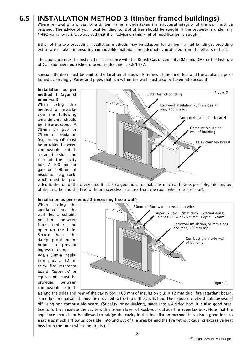
INSTALLATION METHOD 3 (timber framed buildings)Where removal of any part of a timber frame is undertaken the structural integrity of the wall must beretained. The advice of your local building control officer should be sought. If the property is under anyNHBC warranty it is also advised that their advice on this kind of modification is sought.
Either of the two preceding installation methods may be adapted for timber framed buildings, providingextra care is taken in ensuring combustible materials are adequately protected from the effects of heat.
The appliance must be installed in accordance with the British Gas documents DM2 and DM3 or the Instituteof Gas Engineers published procedure document IGE/UP/7.
Special attention must be paid to the location of studwork frames of the inner leaf and the appliance posi-tioned accordingly. Wires and pipes that run within the wall must also be taken into account.
Installation as permethod 1 (againstinner wall)When using thismethod of installa-tion the followingamendments shouldbe incorporated. A75mm air gap or75mm of insulation(e.g. rockwool) mustbe provided betweencombustible materi-als and the sides andrear of the cavitybox. A 100 mm airgap or 100mm ofinsulation (e.g. rock-wool) must be pro-vided to the top of the cavity box. It is also a good idea to enable as much airflow as possible, into and outof the area behind the fire without excessive heat loss from the room when the fire is off.
Installation as per method 2 (recessing into a wall)When setting theappliance into thewall find a suitableposition betweenframe timbers andopen up the hole.Secure back thedamp proof mem-brane to preventingress of damp.Again 50mm insula-tion plus a 12mmthick fire retardantboard, 'Superlux' orequivalent, must beprovided betweencombustible materi-als and the sides and rear of the cavity box. 100 mm of insulation plus a 12 mm thick fire retardant board,'Superlux' or equivalent, must be provided to the top of the cavity box. The exposed cavity should be sealedoff using non-combustible board, ('Supalux' or equivalent), made into a 4-sided box. It is also good prac-tice to further insulate the cavity with a 50mm layer of Rockwool outside the Superlux box. Note that theappliance should not be allowed to bridge the cavity in this installation method. It is also a good idea toenable as much airflow as possible, into and out of the area behind the fire without causing excessive heatloss from the room when the fire is off.
6.5
8
Figure 7Outer leaf of building
Non combustible back panel
Combustible insidewall of building
Rockwool insulation 75mm sides andrear, 100mm top
False chimney breast
50mm of Rockwool to insulate cavity
Superlux Box, 12mm thick, External dims;Height 677, Width 529mm, Depth 167mm.
Rockwool insulation, 50mm sidesand rear, 100mm top.
Combustible inside wallof building
Figure 8
© 2009 Focal Point Fires plc.

INSTALLATION METHOD 4This method allows for a ‘hole in the wall’ installation of the appliance with the rear part recessedinto the inner leaf of a cavity wall. The structural integrity of the wall must be maintained. The wallmust be non-combustible.
Refer to section 6.4 (recessing into a non-combustible wall). Eko 5530 models : If the appliance is to be wall mounted then the entire base of the appliance must besupported by a non-combustible shelf. It may be desirable for the shape of the shelf to follow the profile ofthe appliance. In this case the footprint of the appliance is shown in figure 10, and any flush fitting shelfdesign may be calculated from the measurements given.Eko 5510 & Eko 5520 models : If the appliance is to be wall mounted then the entire base of the appliancemust be supported by a non-combustible shelf. The dimensions of such a shelf are given in section 4.0 (siterequirements).
FINAL FITTINGIf not previously carried out, insert the firebox into the opening. If the appliance is to be screw fixed to theback panel/wall or inside of the opening then suitable locations for such fixings should be established, anda suitable number and type of such fixings should be established to ensure the appliance is securely fixed.There are no purpose provided screw fixing points provided on the firebox as the location of these pointswill vary from installation to installation, depending on the strength of the surrounding materials and thevarious sizes of opening that the appliance may be required to fit into. A cable fixing kit, however, is pro-vided and should be used wherever possible as the default fixing method.Carefully insert the firebox into the opening and guide the gas pipe through the sealing grommet into itsfinal routing position and fit the restrictor inlet elbow supplied to the gas pipe. Secure the firebox by insert-ing screws in the previously prepared locations (if screw fixing) or refer to the following section if cable fix-ing.
CABLE FIXINGWhen using this method for fixing, the minimum depth of the opening must be increased from 105 mm to125 mm. This is to allow for the eyebolts and a space for the cable tensioning. Remove the appliance glasspanel by removal of the four retaining screws. Remove theburner unit - refer to section 9.2.
Drill four holes as shown in figure 11 and fit the fibrerawlplugs. If the fireplace does not allow for the exact lay-out shown, the eyebolts should be fixed to give as similar aconfiguration as possible. Thread both tensioning cablesthrough the holes in the protruding tabs on the rear of thefirebox then through the eyelets and back through the lowerholes in the firebox.
Push the firebox back into the fireplace, centralise, pull theloose cables through the holes and into the bottom of thecavity box. Thread the cable tensioners onto the cables withthe nuts screwed down close to the tensioner head. Slidethe screwed nipple onto the cable, pull cable taut and tight-en nipple. Adjust tensioner using a suitable spanner to pullthe appliance back into position, to allow an even pullaround the fireplace opening. Visually inspect and repeat if necessary to achieve a good fit.
Note: Surplus cable MUST NOT be cut off, as this will prevent proper re-installation after servicing.Coil up the surplus cable and tuck the coils out of the way.
6.6
7.0
9
555
405
504
40
192
92
Figure 10All dimensions in mmFigure 9
7.1
A
B
C
A. 350 mmB. 330 mmC. 70 mmDimension ‘A’can be +/-10mm
Figure 11
© 2009 Focal Point Fires plc.
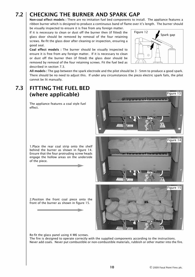
CHECKING THE BURNER AND SPARK GAPNon-coal effect models : There are no imitation fuel bed components to install. The appliance features aribbon burner which is designed to produce a continuous band of flame over it’s length. The burner shouldbe visually inspected to ensure it is free from any foreign matter. If it is necessary to clean or dust off the burner then (if fitted) theglass door should be removed by removal of the four retainingscrews. Re-fit the glass door after cleaning or inspection, ensuring agood seal. Coal effect models : The burner should be visually inspected toensure it is free from any foreign matter. If it is necessary to cleanor dust off the burner then (if fitted) the glass door should beremoved by removal of the four retaining screws. Fit the fuel bed asdescribed in section 7.3.All models : The gap between the spark electrode and the pilot should be 3 - 5mm to produce a good spark.There should be no need to adjust this. If under any circumstances the piezo electric spark fails, the pilotcannot be lit manually.
FITTING THE FUEL BED(where applicable)
The appliance features a coal style fueleffect.
1.Place the rear coal strip onto the shelfbehind the burner as shown in figure 14.Ensure that the four protruding screw headsengage the hollow areas on the undersideof the piece.
2.Position the front coal piece onto thefront of the burner as shown in figure 15.
Re-fit the glass panel using 4 M6 screws.The fire is designed to operate correctly with the supplied components according to the instructions. Never add coals. Never put combustible or non-combustible materials, rubbish or other matter into the fire.
7.3
10
7.2
Figure 12Spark gap
Figure 13
Figure 14
Figure 15
© 2009 Focal Point Fires plc.

FITTING THE DECORATIVE FRAME, FRONT AND HOODThe appliance is supplied with a decorative frame and hood. Attach the hood using two M6 screws asshown in figure 16.
Eko 5510 & Eko 5520 models : Remove all protec-tive film from the frame. The frame is retained byfour magnets on the front face of the firebox.Position the frame onto the magnets.IMPORTANT : Due to the possibility of sharp edges,care should be taken when handling the frame. Theuse of protective gloves is recommended.Place the firefront into position in front of the fire.Do not use any other firefront other than the onesupplied with this appliance. The firefront shown inthese instructions may differ from the one suppliedwith the appliance.
Eko 5530 models : Hang the decorative faciaassembly onto the firebox as shown in figure 17.Secure in position using two no.8 self tappingscrews as shown in figure 18.
TESTING ANDCOMMISSIONINGTurn on and test the gas supply up to the fire for
any leaks, in accordance with the current edition of
BS6891.
OPERATING THE APPLIANCEThe control knob is supplied in the loose parts pack. Fit the control knob onto the valve spindle as shownin figure 19.
The pilot is visible behind the left hand side of the burner. Push in and turn the control knob to the SPARKposition, and hold there for a few seconds. Continue turning anti-clockwise through the spark click to thePILOT light position, ensuring the pilot has lit. If not, return the knob clockwise, and repeat.
When the pilot lights after the spark, keep the knob depressed for approximately ten seconds. Now releasethe knob and the pilot should stay alight. If the pilot is extinguished during use, wait three minutes beforerepeating the ignition procedure.
To achieve the HIGH setting, push the control knobin slightly and continue turning anti-clockwise tothe high position. The main burner should lightafter a few seconds. To decrease the setting tolow, turn the control knob clockwise to the LOWsetting.
To turn to the PILOT position from the HIGH or LOWpositions, press the control knob in, and return tothe pilot position and release. To turn the fire off,keep the knob pressed in, return to the OFF posi-tion and release.
11
7.4
8.0
Figure 16
8.1
Figure 19
Figure 17 Figure 18
© 2009 Focal Point Fires plc.

SETTING PRESSUREThe pressure test point is located on the left hand side ofthe appliance, on the main burner pipe, next to the brassrestrictor/connector. Release the setting pressure test pointscrew (shown in figure 20), and attach a pressure gauge.
Light the fire on the HIGH setting.
To commission the appliance, the burner pressure must bein accordance with the figures stated in section 2.0 of theseinstructions. The fire is factory set to achieve these pres-sures and any significant variation could indicate a supplyproblem. If the pressure is too high, the gas supply metermay be set incorrectly. This should be checked with the firerunning and if necessary reset by the gas supplier.
If the burner pressure is too low, then check the inlet pres-sure with the appliance running. If this is less than the inlet pressure stated in section 2.0 of these instruc-tions it will need to be reset by the gas supplier. If the setting pressure is too low, but the meter pressureis acceptable, then a problem in the supply pipework is to be suspected.
Upon satisfactory checking of the burner pressure, turn the fire off, disconnect the pressure gauge and refitthe test point screw. Light the fire and check for gas soundness.
In the event that the burner pressure is not in accordance with the figures stated in the data section of theseinstructions, the appliance must not be commissioned, and the manufacturer should be contacted for guid-ance.
BRIEFING THE CUSTOMERAll instructions must be handed to the user for safekeeping. Show the customer how to light and controlthe fire.After commissioning the appliance, the customer should be instructed on the safe use of the appliance andthe need for regular servicing. Frequency of service depends on usage, but MUST be carried out at leastonce annually. Advise that cleaning of the fire maybe achieved when the fire is cold using a damp cloth andmild detergent on most surfaces. Advise that the fire will emit a "newness" smell for a time after initial com-missioning and that extra ventilation may be needed during this time. Recommend that a guard be usedfor the protection of young children, pets, the elderly and the infirm.
SERVICINGIsolate the fire from the gas supply. Ensure that the fire is fully cold before attempting service. A sug-gested procedure for servicing is detailed below.
1. Lay out the dustsheet and tools.2. Remove the frame and front/facia and then remove the hood (two M6 screws).3. Remove the glass door assembly (four M6 screws) and clean carefully.4. Coal effect models only : Carefully remove the ceramic components.5. Inspect the catalyst and clean if necessary with a soft brush.6. Disconnect the gas supply and remove the four screws retaining the burner (two in the burner
legs and two in the rear of the firebox).7. Lift away burner assembly.8. Strip off the burner pipes and clean thoroughly.9. Clean the in-line restrictor, pilot assembly and the burner tube. Do not attempt to remove the
pilot injector as this can cause damage.10. Re-assemble and re-fit the burner tray.11. Turn on the gas supply and leak test. Check pilot and burner for good ignition.12. Coal effect models only : Refit the ceramics as per these installation instructions.13. Refit the glass door assembly, ensuring a good seal.14. Refit the hood.15. Check any purpose provided ventilation is un-obstructed. 16. Light the fire and check setting pressures.17. Carry out combustion check as per section 9.4.17. Check safe operation of the appliance.
For specific servicing instructions, see relevant sections.12
8.2
8.3
9.0
Figure 20
© 2009 Focal Point Fires plc.

CLEANING THE CERAMICSRemove the frame and front/facia and place to one side. Remove the hood. Remove the glass door assem-bly. Remove the ceramic components. Gently clean in the open air with a soft brush. Be careful not to cre-ate dust from the ceramics. Where necessary replace damaged components with genuine spares. Seal scrapceramic components in plastic bags and dispose at proper refuse sites as directed. If using a vacuum clean-er a HEPA filtering system is recommended.
Re-fit the ceramics by referring to the relevant section of these instructions. Refit the glass door assemblyensuring a good seal. Refit the hood, front and frame/facia.
SERVICING THE BURNER TRAY AND GAS ASSEMBLYFirstly, remove the front, frame/facia and hood, the glass panel (Coal effect models : remove ceramics),data plate and disconnect the gas connection atthe isolator elbow. Remove the burner tray byremoving the four securing screws shown in fig-ure 21.
Remove the pilot and main burner pipes andblow through to dislodge any debris. Nowremove the restrictor elbow and blow through tomake sure it is entirely clear. Unclip the pilot lintgauze and clean with a soft brush. Clean theexterior of the pilot assembly with a soft brushand blow through the flame ports on the pilothead. Check the aeration holes are free from lintor dirt. The pilot assembly can be removed ifrequired by disconnecting the electrode HT lead,gas pipe and unscrewing the mounting screws and lifting away.
The pilot assembly is a non-serviceable item and should not be taken apart. Aeration holes must beabsolutely clear internally for proper operation. NEVER MODIFY OR BEND THE THERMOCOUPLE TO MAKETHE PILOT STAY ALIGHT. Modifications are dangerous and can have serious unseen effects on safety. Ifthe pilot will not stay lit there is a problem with dirt, the gas supply to it, or the thermocouple needsreplacement.
The gas valve is a non-serviceable item. If this needs replacement, remove M4 securing screw holding thevalve in place, remove all pipe unions, electrode lead, thermocouple lead and then the complete valve.Replacement must be original manufacturers parts. Re-assembly is the reverse of removal. Ensure settingpressures are as stated in Section 2; Appliance Data.
Re-assembly in the reverse of removal.
PILOT ASSEMBLYClean the pilot assembly with a soft brush and blow through. Check the aeration holes are free of any dirtor lint. Clean thoroughly internally, the connection can be removed from the base of the pilot unit usingtwo spanners to make cleaning easier. Do not damage or try to dismantle the pilot injector.
The unit is factory set and the only check necessary is to ensure the spark gap is correct. See specifica-tions for gas setting.
NEVER MODIFY OR BEND THE THERMOCOUPLE TO MAKE THE PILOT STAY ALIGHT. If the pilot will notstay lit there is a problem with dirt, the gas supply, or the thermocouple needs replacement. Modificationsare dangerous and can have a serious unseen effect on safety and therefore MUST not be done.Replacements must be original manufacturers parts. Re-assemble in the reverse of removal. Ensure settingpressures are as stated in Section 2; Appliance Data.
9.2
9.1
9.3
Figure 21
13© 2009 Focal Point Fires plc.
CATALYSTIt is recommended that the catalytic converter is inspected for signs of damage and dirt during routine serv-icing procedures. The expected life of the catalyst is in excess of 11,000 hours (10 years of normal use).After this time the catalytic converter should be replaced.
If there are any deposits of dirt or soot on the catalyst they should be cleaned with a soft brush and a vac-uum cleaner. If removed for cleaning ensure the seals are in good condition before replacing the catalyticconverter. New seals will usually be required.
The performance of the catalyst may be checked using an analyser as follows. Any analyser used shouldconform to BS7927 : 1998 + A1 : 1999 or BS EN 50379-3.
Important: The temperature of the gases emmited by the catalytic converter is in excess of 400 oC.Measuring gas of this temperature may damage some types of gas analysers. If in doubt consult theequipment manufacturer.
Position gas sample probe directly in front of the catalyst underneath the hood, in the centre of the upperfirebox. Ignite the fire as per the operating instructions, and run at high setting for 15 minutes. Record thecarbon dioxide (CO2) concentration and then the carbon monoxide (CO) concentration as displayed by theanalyser - also noting the units in which the values are expressed.
Most analysers display carbon dioxide (CO2) concentrations in percentage (%) terms and carbon monoxideconcentration in parts per million (ppm) terms.
In order to calculate the combustion ratio for the appliance (CO/CO2) it is first necessary to express bothgas concentrations in terms of percentage. To convert from parts per million (ppm) to a percentage (%)divide the ppm figure by 10,000. Examples : 35ppm = 0.0035%, 15ppm = 0.0015%, 5ppm = 0.0005%.
Now divide the concentration of carbon monoxide (CO) expressed in percent by the concentration of car-bon dioxide (CO2) to obtain the appliance combustion ratio.
The combustion ratio of the gasses emitted by the catalytic convertor should not exceed 0.0015.
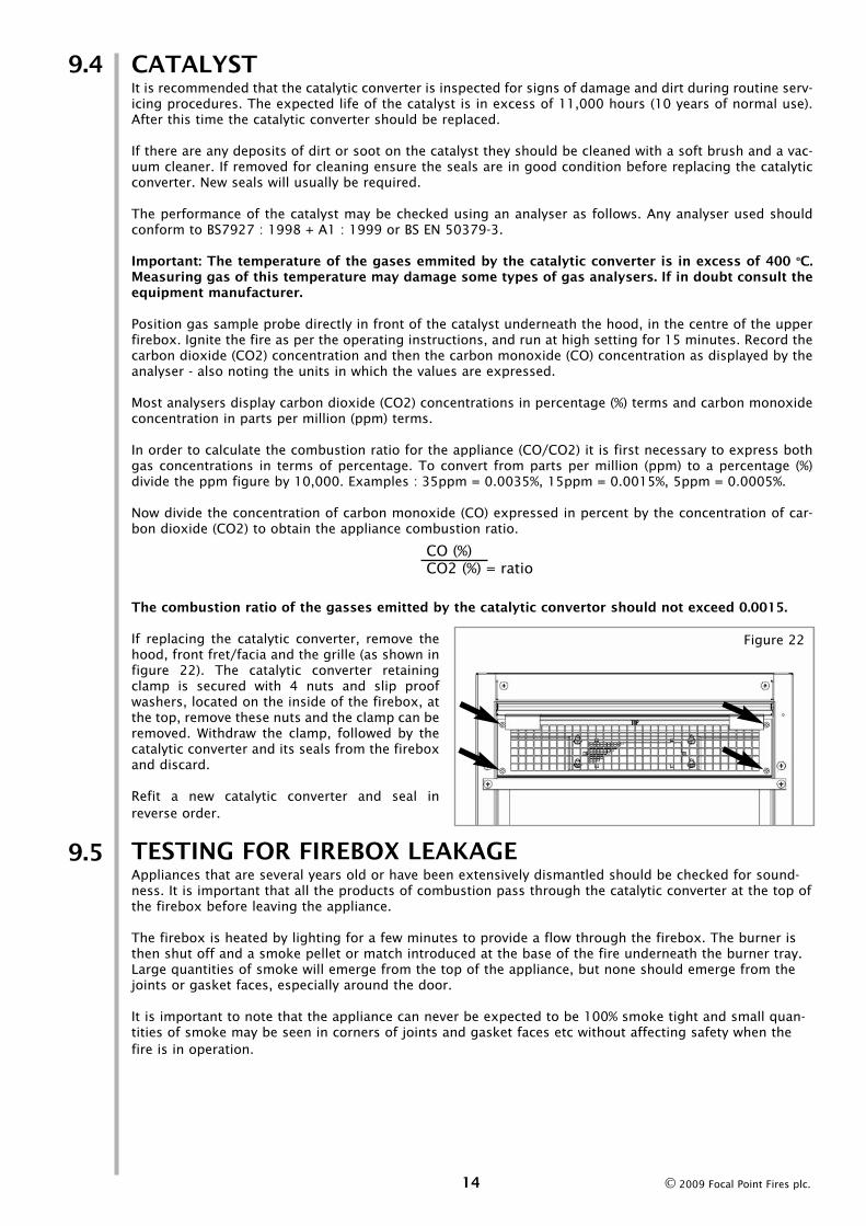
If replacing the catalytic converter, remove thehood, front fret/facia and the grille (as shown infigure 22). The catalytic converter retainingclamp is secured with 4 nuts and slip proofwashers, located on the inside of the firebox, atthe top, remove these nuts and the clamp can beremoved. Withdraw the clamp, followed by thecatalytic converter and its seals from the fireboxand discard.
Refit a new catalytic converter and seal inreverse order.
TESTING FOR FIREBOX LEAKAGEAppliances that are several years old or have been extensively dismantled should be checked for sound-ness. It is important that all the products of combustion pass through the catalytic converter at the top ofthe firebox before leaving the appliance.
The firebox is heated by lighting for a few minutes to provide a flow through the firebox. The burner isthen shut off and a smoke pellet or match introduced at the base of the fire underneath the burner tray.Large quantities of smoke will emerge from the top of the appliance, but none should emerge from thejoints or gasket faces, especially around the door.
It is important to note that the appliance can never be expected to be 100% smoke tight and small quan-tities of smoke may be seen in corners of joints and gasket faces etc without affecting safety when thefire is in operation.
9.4
9.5
CO (%)CO2 (%) = ratio
Figure 22
14 © 2009 Focal Point Fires plc.
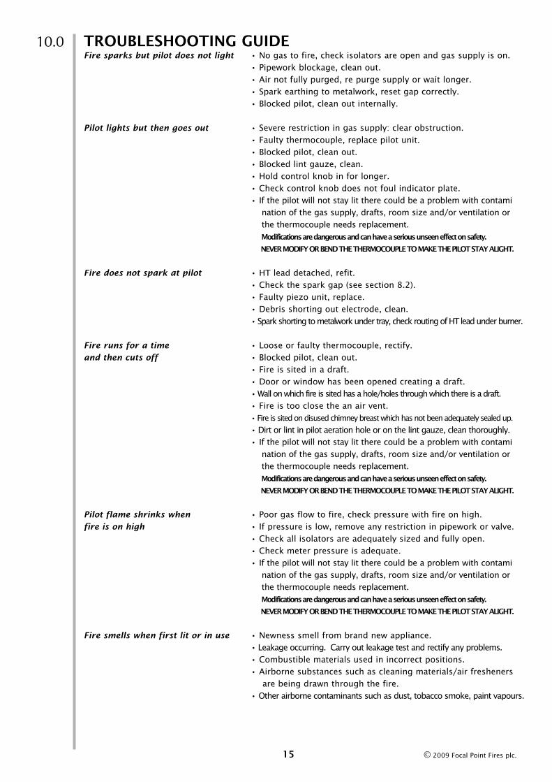
TROUBLESHOOTING GUIDEFire sparks but pilot does not light • No gas to fire, check isolators are open and gas supply is on.
• Pipework blockage, clean out. • Air not fully purged, re purge supply or wait longer. • Spark earthing to metalwork, reset gap correctly. • Blocked pilot, clean out internally.
Pilot lights but then goes out • Severe restriction in gas supply: clear obstruction. • Faulty thermocouple, replace pilot unit. • Blocked pilot, clean out. • Blocked lint gauze, clean. • Hold control knob in for longer. • Check control knob does not foul indicator plate.• If the pilot will not stay lit there could be a problem with contami
nation of the gas supply, drafts, room size and/or ventilation or the thermocouple needs replacement.Modifications are dangerous and can have a serious unseen effect on safety.
NEVER MODIFY OR BEND THE THERMOCOUPLE TO MAKE THE PILOT STAY ALIGHT.
Fire does not spark at pilot • HT lead detached, refit. • Check the spark gap (see section 8.2).• Faulty piezo unit, replace. • Debris shorting out electrode, clean. • Spark shorting to metalwork under tray, check routing of HT lead under burner.
Fire runs for a time • Loose or faulty thermocouple, rectify. and then cuts off • Blocked pilot, clean out.
• Fire is sited in a draft.• Door or window has been opened creating a draft.• Wall on which fire is sited has a hole/holes through which there is a draft.• Fire is too close the an air vent.• Fire is sited on disused chimney breast which has not been adequately sealed up.
• Dirt or lint in pilot aeration hole or on the lint gauze, clean thoroughly. • If the pilot will not stay lit there could be a problem with contami
nation of the gas supply, drafts, room size and/or ventilation or the thermocouple needs replacement.Modifications are dangerous and can have a serious unseen effect on safety.
NEVER MODIFY OR BEND THE THERMOCOUPLE TO MAKE THE PILOT STAY ALIGHT.
Pilot flame shrinks when • Poor gas flow to fire, check pressure with fire on high. fire is on high • If pressure is low, remove any restriction in pipework or valve.
• Check all isolators are adequately sized and fully open. • Check meter pressure is adequate. • If the pilot will not stay lit there could be a problem with contami
nation of the gas supply, drafts, room size and/or ventilation or the thermocouple needs replacement.Modifications are dangerous and can have a serious unseen effect on safety.
NEVER MODIFY OR BEND THE THERMOCOUPLE TO MAKE THE PILOT STAY ALIGHT.
Fire smells when first lit or in use • Newness smell from brand new appliance. • Leakage occurring. Carry out leakage test and rectify any problems. • Combustible materials used in incorrect positions.• Airborne substances such as cleaning materials/air fresheners
are being drawn through the fire.• Other airborne contaminants such as dust, tobacco smoke, paint vapours.
10.0
15 © 2009 Focal Point Fires plc.

U S E R I N S T R U C T I O N S
Section Contents Page No
1.0 Important Notes 12.0 Fire Front/Facia 23.0 Clearances to Combustibles 24.0 Ventilation and Room Size 35.0 Operating Instructions 36.0 Combustion Monitoring System 37.0 Fitting the Fuel Bed 48.0 Cleaning 49.0 Servicing 4
10.0 List of Replacement Parts 4
IMPORTANT NOTES
• The installation and Servicing of this fire MUST only be carried out by a GAS SAFE registered person in
accordance with local Codes and/or Regulations, Building Regulations and the manufacturer's instruc-
tions.Failure to comply with the above could lead to prosecution and invalidate the appliance warranty. In
the event of gas leakage from the appliance, the gas supply must be turned off at the nearest isolating
valve. This appliance is only suitable for the gas type for which it is supplied.
• Keep a note of the installer's name and address, the original purchase receipt and the date of installation.
Failure to produce this information may invalidate the warranty. The appliance should be serviced regular-
ly to ensure continued safe operation. See the servicing section for further reference.
• The guard (glass front) is to prevent risk of fire or injury from burns and no part of it should be perma-
nently removed. It Does Not Give Full Protection For Young Children Or The Infirm. Parts of this appli-
ance become naturally hot during use. It is recommended that a suitable fireguard is used, especially where
young children, pets, the elderly or infirm are concerned. The manufacturer of this appliance considers all
surfaces as working surfaces with the exception of the control knob and control panel.
• Combustible items, such as flooring and furniture and soft wall coverings (such as blown vinyl or
embossed paper), low temperature surrounds etc may discolour if fitted too close to the fire. See relevant
section for further details on clearances to combustibles. No combustible materials or flooring should pro-
trude onto the hearth (if fitted).
• This appliance incorporates a combustion monitoring system (ODS).
• DO NOT burn any foreign material on this fire. Under no circumstances shall the appliance be used if the
glass front door or panel has been removed, damaged or is open. On no account should the appliance inlet
or outlet openings be blocked or obstructed in any way (see figure 1). DO NOT place objects on top of the
appliance.
• WARNING: Due to the nature of this product the area around the top of the appliance (i.e. the grille) gets
very hot. Care should be taken when operating the appliance.
The integral catalysts should be checked by the installer upon servicing to ensure there are no defects or
obstructions that may prevent the satisfactory flow of combustion products. The expected life of the cata-
lyst is in excess of 11,000 hours (10 years of normal use). After this time the catalyst should be replaced.
1.0
1 © 2009 Focal Point Fires plc.
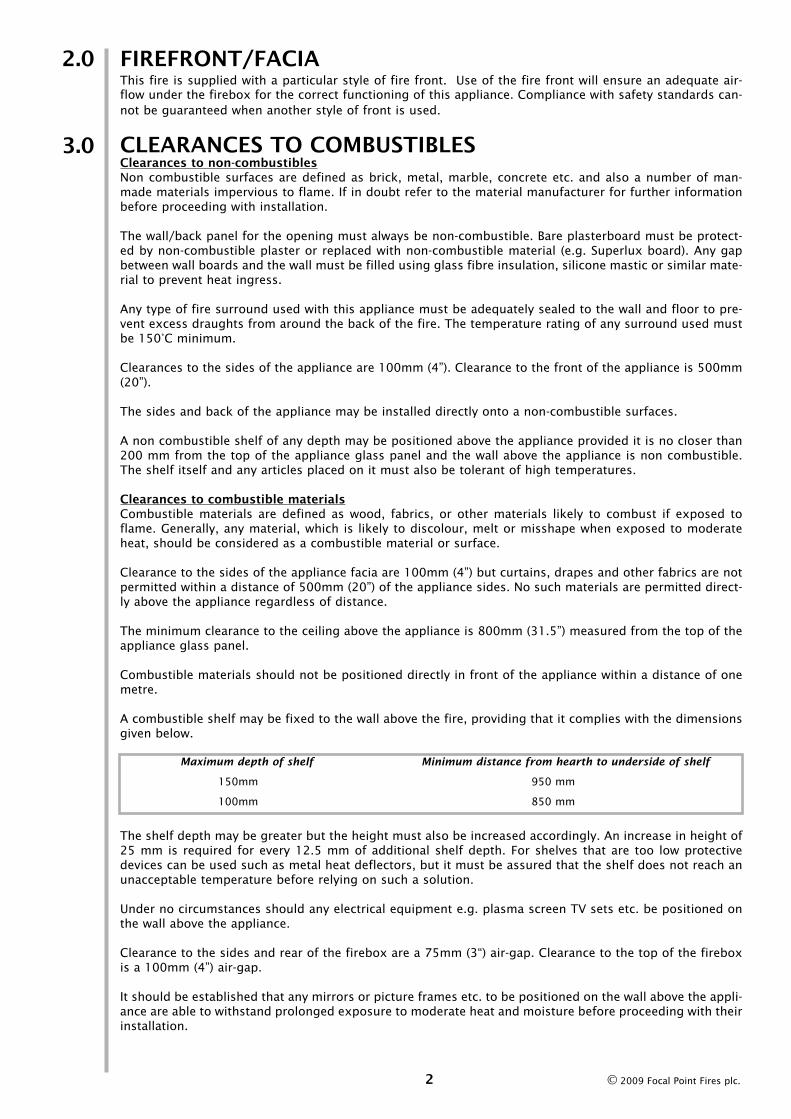
FIREFRONT/FACIAThis fire is supplied with a particular style of fire front. Use of the fire front will ensure an adequate air-flow under the firebox for the correct functioning of this appliance. Compliance with safety standards can-not be guaranteed when another style of front is used.
CLEARANCES TO COMBUSTIBLESClearances to non-combustiblesNon combustible surfaces are defined as brick, metal, marble, concrete etc. and also a number of man-made materials impervious to flame. If in doubt refer to the material manufacturer for further informationbefore proceeding with installation.
The wall/back panel for the opening must always be non-combustible. Bare plasterboard must be protect-ed by non-combustible plaster or replaced with non-combustible material (e.g. Superlux board). Any gapbetween wall boards and the wall must be filled using glass fibre insulation, silicone mastic or similar mate-rial to prevent heat ingress.
Any type of fire surround used with this appliance must be adequately sealed to the wall and floor to pre-vent excess draughts from around the back of the fire. The temperature rating of any surround used mustbe 150°C minimum.
Clearances to the sides of the appliance are 100mm (4”). Clearance to the front of the appliance is 500mm(20”).
The sides and back of the appliance may be installed directly onto a non-combustible surfaces.
A non combustible shelf of any depth may be positioned above the appliance provided it is no closer than200 mm from the top of the appliance glass panel and the wall above the appliance is non combustible.The shelf itself and any articles placed on it must also be tolerant of high temperatures.
Clearances to combustible materialsCombustible materials are defined as wood, fabrics, or other materials likely to combust if exposed toflame. Generally, any material, which is likely to discolour, melt or misshape when exposed to moderateheat, should be considered as a combustible material or surface.
Clearance to the sides of the appliance facia are 100mm (4”) but curtains, drapes and other fabrics are notpermitted within a distance of 500mm (20”) of the appliance sides. No such materials are permitted direct-ly above the appliance regardless of distance.
The minimum clearance to the ceiling above the appliance is 800mm (31.5”) measured from the top of theappliance glass panel.
Combustible materials should not be positioned directly in front of the appliance within a distance of onemetre.
A combustible shelf may be fixed to the wall above the fire, providing that it complies with the dimensionsgiven below.
The shelf depth may be greater but the height must also be increased accordingly. An increase in height of25 mm is required for every 12.5 mm of additional shelf depth. For shelves that are too low protectivedevices can be used such as metal heat deflectors, but it must be assured that the shelf does not reach anunacceptable temperature before relying on such a solution.
Under no circumstances should any electrical equipment e.g. plasma screen TV sets etc. be positioned onthe wall above the appliance.
Clearance to the sides and rear of the firebox are a 75mm (3“) air-gap. Clearance to the top of the fireboxis a 100mm (4”) air-gap.
It should be established that any mirrors or picture frames etc. to be positioned on the wall above the appli-ance are able to withstand prolonged exposure to moderate heat and moisture before proceeding with theirinstallation.
2.0
3.0
2
Maximum depth of shelf Minimum distance from hearth to underside of shelf
150mm 950 mm
100mm 850 mm
© 2009 Focal Point Fires plc.

VENTILATION AND ROOM SIZEPurpose provided ventilation of 100cm2 is required for this appliance. An openable window or equivalent isalso required. Any ventilation fitted must comply with BS 5871 part 4 and BS 5440 part 2. Ventilation fit-ted under, or within immediate vicinity of the appliance must not be used as it may adversely effect per-formance of the combustion monitoring system (ODS) system. The appliance shall not be installed within1 metre of any existing air vent, and any new air vent shall not be installed within 1 metre of the appliance.
The requirements of other appliances operating in the space or room must be taken into considerationwhen assessing ventilation requirements, this will have been carried out by your GAS SAFE registeredinstaller. A supply of fresh air into the room is advisable to maintain temperatures within limits.
This appliance must not be installed in a bedroom or a bathroom. For Republic of Ireland, see relevant rulesin force.
The room size should be a minimum of 27m3 (e.g. 11’ x 11’ x 8’) to allow adequate circulation of air andensure the correct operation of the fire. This volume may include adjacent spaces but these spaces must notbe separated by a door. Note : To calculate a room size in cubic metres (m3) divide the room volume in cubicfeet (ft3) by 35.3.
It should be noted that heaters create warm air currents. These currents move heat to wall surfaces nextto the heater. Installing the heater next to vinyl or cloth wall coverings or operating the heater where impu-rities in the air (such as tobacco smoke, candle smoke etc.) exist, may cause the walls to become dis-coloured.
This appliance is intended as a secondary source of heat only and should not be used in a room withoutsome form of background heating present. If the appliance is used in a room as the sole source of heat,then condensation may occur on colder surfaces within the room.
OPERATING INSTRUCTIONS The control knob is marked as shown in figure 1. The pilot is visible behind the left hand side of the burn-er. Push in and turn the control knob to the SPARKposition, and hold there for a few seconds.Continue turning anti-clockwise through the sparkclick to the PILOT light position, ensuring the pilothas lit. If not, return the knob clockwise, andrepeat.
When the pilot lights after the spark, keep the knobdepressed for approximately ten seconds. Nowrelease the knob and the pilot should stay alight. Ifthe pilot is extinguished during use, wait threeminutes before repeating the ignition procedure.
To achieve the HIGH setting, push the control knobin slightly and continue turning anti-clockwise tothe high position. The main burner should lightafter a few seconds. To decrease the setting to low, turn the control knob clockwise to the LOW setting.
To turn to the PILOT position from the HIGH or LOW positions, press the control knob in, and return to thepilot position and release. To turn the fire off, keep the knob pressed in, return to the OFF position andrelease.
COMBUSTION MONITORING SYSTEMThis fire is fitted with a combustion monitoring safety device (ODS). If the fire shuts down during use forno apparent reason then several reasons may be suspected. If a door or window has been opened creat-ing a draught, then pilot disturbance could be the problem and removal of the draught should resolve this.The fire can then be re-lit in accordance with the previous section. A grommet seal may also be missingfrom the firebox causing abnormal draught to shut down the pilot. Call your installer to check seals areproperly fitted.
If pilot disturbance is not the cause, then the ODS safety system may be in operation. Switch the applianceOFF, call in your installer to check the appliance and ventilation. Remedial work must be carried out asrequired. DO NOT allow the appliance to be used until the appliance and installation is passed as safe. Ifthe pilot continues to be extinguished you must call your installer to check the operation of the completeappliance.
3
4.0
5.0
Figure 1
6.0
© 2009 Focal Point Fires plc.
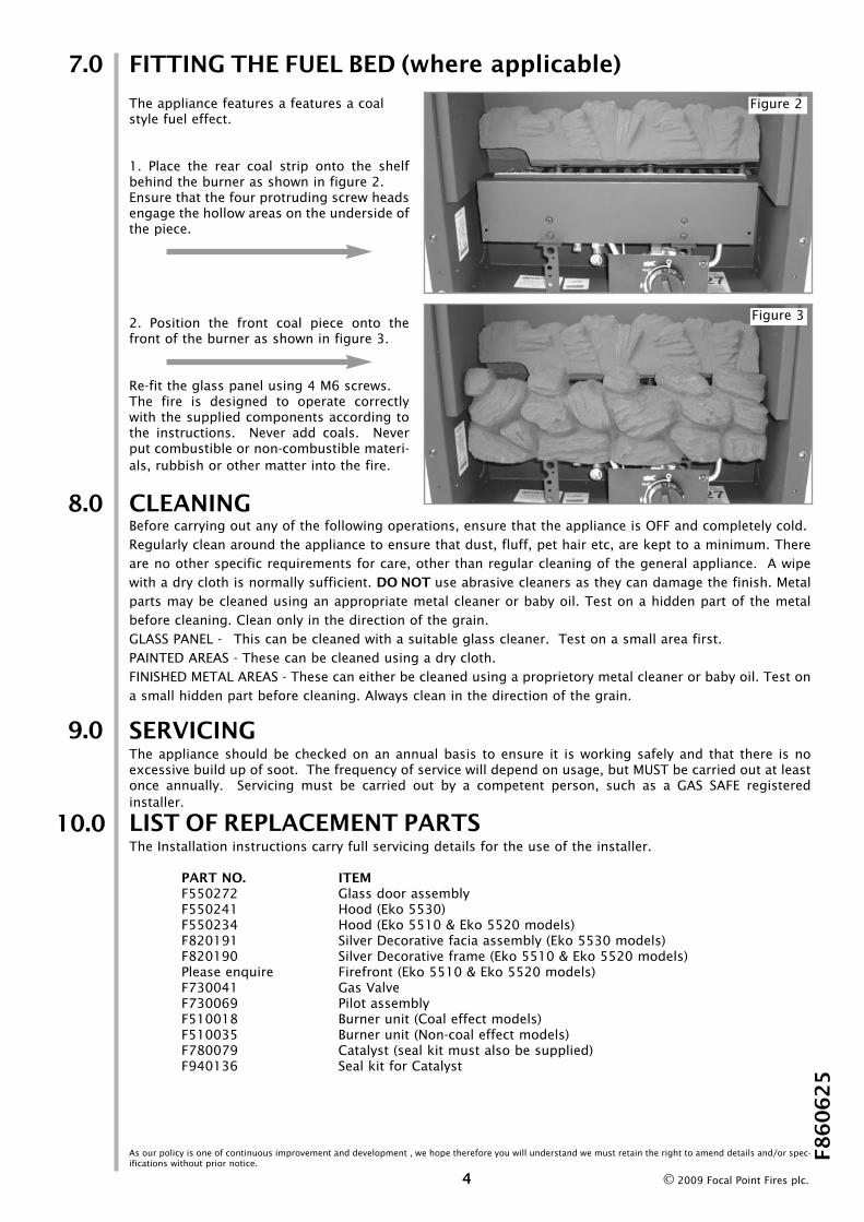
FITTING THE FUEL BED (where applicable)
The appliance features a features a coalstyle fuel effect.
1. Place the rear coal strip onto the shelfbehind the burner as shown in figure 2.Ensure that the four protruding screw headsengage the hollow areas on the underside ofthe piece.
2. Position the front coal piece onto thefront of the burner as shown in figure 3.
Re-fit the glass panel using 4 M6 screws.The fire is designed to operate correctlywith the supplied components according tothe instructions. Never add coals. Neverput combustible or non-combustible materi-als, rubbish or other matter into the fire.
CLEANINGBefore carrying out any of the following operations, ensure that the appliance is OFF and completely cold. Regularly clean around the appliance to ensure that dust, fluff, pet hair etc, are kept to a minimum. Thereare no other specific requirements for care, other than regular cleaning of the general appliance. A wipewith a dry cloth is normally sufficient. DO NOT use abrasive cleaners as they can damage the finish. Metalparts may be cleaned using an appropriate metal cleaner or baby oil. Test on a hidden part of the metalbefore cleaning. Clean only in the direction of the grain. GLASS PANEL - This can be cleaned with a suitable glass cleaner. Test on a small area first.PAINTED AREAS - These can be cleaned using a dry cloth.FINISHED METAL AREAS - These can either be cleaned using a proprietory metal cleaner or baby oil. Test ona small hidden part before cleaning. Always clean in the direction of the grain.
SERVICINGThe appliance should be checked on an annual basis to ensure it is working safely and that there is noexcessive build up of soot. The frequency of service will depend on usage, but MUST be carried out at leastonce annually. Servicing must be carried out by a competent person, such as a GAS SAFE registeredinstaller.
LIST OF REPLACEMENT PARTSThe Installation instructions carry full servicing details for the use of the installer.
PART NO. ITEMF550272 Glass door assemblyF550241 Hood (Eko 5530)F550234 Hood (Eko 5510 & Eko 5520 models)F820191 Silver Decorative facia assembly (Eko 5530 models)F820190 Silver Decorative frame (Eko 5510 & Eko 5520 models)Please enquire Firefront (Eko 5510 & Eko 5520 models)F730041 Gas ValveF730069 Pilot assemblyF510018 Burner unit (Coal effect models)F510035 Burner unit (Non-coal effect models)F780079 Catalyst (seal kit must also be supplied)F940136 Seal kit for Catalyst
7.0
Figure 2
Figure 3
10.0
8.0
9.0
As our policy is one of continuous improvement and development , we hope therefore you will understand we must retain the right to amend details and/or spec-ifications without prior notice.
F8
60
62
5
4 © 2009 Focal Point Fires plc.