installation and user instructions - carrier
TRANSCRIPT

Installation and User InstructionsNOTE: Read the entire instruction manual before starting the installation.
IMPORTANT: SAVE THESE INSTRUCTIONS.
A200586
A200587ARegister your product online at: https://www.cac-bdp-all.com/
RESIDENTIAL USE ONLYPlease take note that this manual uses the following symbols toemphasize particular information:
Recognize safety information. When you see this symbol on the unitand in instructions or manuals, be alert to the potential for personalinjury. Understand the signal words DANGER, WARNING, andCAUTION. These words are used with the safety-alert symbol.DANGER identifies the most serious hazards, which will result in severepersonal injury or death. WARNING signifies hazards, which couldresult in personal injury or death. CAUTION is used to identify unsafepractices, which may result in minor personal injury or product andproperty damage. NOTE is used to highlight suggestions which willresult in enhanced installation, reliability, or operation.LIMITATIONFor residential (domestic) installation only. Installation work andelectrical wiring must be done by a qualified person in accordance withall applicable codes and standards, including fire-rated constructioncodes and standards.
TABLE OF CONTENTSLIMITATION . . . . . . . . . . . . . . . . . . . . . . . . . . . . . . . . . . . . . . . . 1
INSTALLER INFORMATION . . . . . . . . . . . . . . . . . . . . . . . . . . . . . 2USER INFORMATION . . . . . . . . . . . . . . . . . . . . . . . . . . . . . . . . . . . 2
Optional Wall Control . . . . . . . . . . . . . . . . . . . . . . . . . . . . . . . . . . 2User Servicing Instructions . . . . . . . . . . . . . . . . . . . . . . . . . . . . . . 2Comfort Mode . . . . . . . . . . . . . . . . . . . . . . . . . . . . . . . . . . . . . . . . 3Planning . . . . . . . . . . . . . . . . . . . . . . . . . . . . . . . . . . . . . . . . . . . . . 3
Installation Zones . . . . . . . . . . . . . . . . . . . . . . . . . . . . . . . . . . . . 3Installation Types. . . . . . . . . . . . . . . . . . . . . . . . . . . . . . . . . . . . . . 3
Stand-Alone Installation . . . . . . . . . . . . . . . . . . . . . . . . . . . . . . . 3Installation with an AHU . . . . . . . . . . . . . . . . . . . . . . . . . . . . . . 3
Preparation . . . . . . . . . . . . . . . . . . . . . . . . . . . . . . . . . . . . . . . . . . . 3Mounting the Unit. . . . . . . . . . . . . . . . . . . . . . . . . . . . . . . . . . . . 4Flush to Ceiling. . . . . . . . . . . . . . . . . . . . . . . . . . . . . . . . . . . . . . 5Under Ceiling or Wall Mounted . . . . . . . . . . . . . . . . . . . . . . . . . 5Ceiling Hung. . . . . . . . . . . . . . . . . . . . . . . . . . . . . . . . . . . . . . . . 5In the Attic . . . . . . . . . . . . . . . . . . . . . . . . . . . . . . . . . . . . . . . . . 5Connecting the Insulated Ducts to the Unit . . . . . . . . . . . . . . . . 6
WIRING . . . . . . . . . . . . . . . . . . . . . . . . . . . . . . . . . . . . . . . . . . . . . . . 7Wiring and Logic Diagrams. . . . . . . . . . . . . . . . . . . . . . . . . . . . . . 7Connection to the AHU . . . . . . . . . . . . . . . . . . . . . . . . . . . . . . . . . 8Connection to the Supply Fan Optional Wall Control. . . . . . . . . . 8
HOW TO TEST THE UNIT. . . . . . . . . . . . . . . . . . . . . . . . . . . . . . . . 8SERVICE PARTS . . . . . . . . . . . . . . . . . . . . . . . . . . . . . . . . . . . . . . . 9
Replacement Parts and Repair . . . . . . . . . . . . . . . . . . . . . . . . . . . . 9TROUBLESHOOTNG. . . . . . . . . . . . . . . . . . . . . . . . . . . . . . . . . . . 10
FSF Troubleshooting . . . . . . . . . . . . . . . . . . . . . . . . . . . . . . . . . . 10All Units Troubleshooting . . . . . . . . . . . . . . . . . . . . . . . . . . . . . . 11
APPENDIX A. . . . . . . . . . . . . . . . . . . . . . . . . . . . . . . . . . . . . . . . . . 12APPENDIX B. . . . . . . . . . . . . . . . . . . . . . . . . . . . . . . . . . . . . . . . . . 13NOTES PAGE . . . . . . . . . . . . . . . . . . . . . . . . . . . . . . . . . . . . . . . . . 14
FSFXXAOA1180Fresh Air Supply Fan

FSFXXAOA1180: Installation and User Instructions
Manufacturer reserves the right to change, at any time, specifications and designs without notice and without obligations.2
INSTALLER INFORMATIONIMPORTANT: Ducting has a strong effect on the air flow, noise andenergy use of the fan. Use the shortest, straightest duct routing possiblefor best performance, and avoid installing the fan with smaller ducts thanrecommended. Insulation around the ducts can reduce energy loss andinhibit mold growth. Fans installed with existing ducts may not achievetheir rated air flow.NOTE: Make sure that the outdoor intake hood is easily accessible forannual maintenance. If located above the first floor, place it close to awindow or balcony to allow ease of access.
USER INFORMATIONOptional Wall ControlThis unit can be connected to the supply fan wall control.• Upon startup, the wall control LED will light up during the boot
sequence, and remain ON as the unit starts to operate after the bootsequence. Press the push button to turn the unit OFF; the wall controlLED will also turn OFF.
• When it is time to perform the filter maintenance, the wall controlLED will blink slowly (2 seconds ON, 2 seconds OFF). After the filtermaintenance has been performed, press and hold the push button for 5seconds to reset the filter maintenance reminder.
• Refer to your installer for any other blinking pattern.User Servicing Instructions• The metal filter included with this unit should be cleaned every 6
months using water and a mild soap. To remove the filter(s), open thedoor, release the filter retaining clip and pull filter(s) out. Allow thefilter to dry completely before putting it back in the unit; whenreinserting it in the unit, make sure that it is standing straight.
• Inspect the outdoor air intake at least once a year.• During the first year of operation, it is recommended to inspect your
unit at a higher frequency, especially if you live near a highway or inan area where there is a lot of construction work, generating lots ofdust. Your filter(s) may need more frequent cleaning or replacement inthese types of environments.
• Replace the optional MERV filter at least once a year; do not attemptto clean and reuse the optional MERV filter.
• These recommendations may change according to the environmentalconditions in your area.
WARNING!TO REDUCE THE RISK OF FIRE, ELECTRIC SHOCK, OR INJURY TO PERSON(S) OBSERVE THE FOLLOWING
1. Use this unit only in the manner intended by the manufacturer.If you have questions, contact the manufacturer.
2. Before servicing or cleaning this unit, disconnect power cordfrom electrical outlet.
3. This unit is not designed to provide combustion and/or dilutionair for fuel-burning appliances.
4. Do not use this unit with any solid-state speed control deviceother than those specified in (Connection to the AHU on p8).
5. Do not operate any fan with a damaged cord or plug. Discardfan or contact your HVAC contractor, or the manufacturer.
6. Do not run cord under carpeting. Do not cover cord with throwrugs, runners or similar coverings. Do not route cord underfurniture or appliances. Arrange cord away from traffic area andwhere it will not be tripped over.
7. Installation work and electrical wiring must be done byqualified person(s) in accordance with all applicable code andstandards, including fire-rated construction.
8. When cutting or drilling into a wall or ceiling, do not damageelectrical wiring and other hidden utilities.
9. This unit must be grounded.10. When performing installation, servicing or cleaning this unit, it
is recommended to wear safety glasses and gloves.11. When applicable local regulation comprises more restrictive
installation and/or certification requirements, theaforementioned requirements prevail on those of this documentand the installer agrees to conform to these at his own expenses.
12. The unit must be mounted at least 3.3 feet (1.0 meter) awayfrom any accessible opening of the duct.
CAUTION!TO AVOID UNIT DAMAGE AND ENSURE LONG LIFE
1. Please read specification label on product for further information and requirements.
2. Do not intake/exhaust air into spaces within walls or ceiling or into attics, crawl spaces, or garage. Do not attempt to recover the exhaust air from a dryer or a range hood.
3. Intended for residential installation only in accordance with the requirements of NFPA 90B.
4. When leaving the house for a long period of time (more than two weeks), a responsible person should regularly check if the unit operates adequately.
5. At least once a year, the unit mechanical and electronic parts should be inspected by qualified service personnel.
6. Since the electronic control system of the unit uses a microprocessor, it may not operate correctly because of external noise or very short power failure. If this happens, unplug the unit and wait approximately 10 seconds. Then, plug the unit in again.
7. Outdoor intake hood must be weather tight and comprise a bird screen.
8. Should you decide to dispose of this unit or of parts of it, do so in accordance with local laws and regulation.
9. Some areas are prone to a higher frequency of lightning-induced power surges. Using a surge protector to protect units located in these areas is recommended.

FSFXXAOA1180: Installation and User Instructions
Manufacturer reserves the right to change, at any time, specifications and designs without notice and without obligations.3
Comfort ModeShould the air inside your house become too humid, or if such conditionswant to be prevented, the operation mode of your Supply Fan can bechanged from a Code-Compliant one (modes 1 to 3) to a Comfort Mode(modes A to E). Refer to the map in (APPENDIX A on p12) to make theright choice.When making such change, make sure to only change the Mode and toleave the Run time % as it was set by your installer. If in doubt, refer toyour HVAC contractor.
PlanningInstallation ZonesThe FSFXXAOA1180 unit can be installed in climatic zones 1 to 4 asdefined by the Department of Energy (refer to (APPENDIX A on p12)for the map), whether as a stand alone unit or connected to the ducting ofan AHU. Installation in any other climatic zone may cause damage to thehouse.Installation TypesIMPORTANT: Always use insulated ducting of a minimum R-4insulation factor. Duct diameter equal or larger than port size isrecommended.Stand-Alone InstallationThe installer shall ensure that, if necessary, an in-line heater sizedaccording to required airflow and outside design heating temperaturefrom Manual J or ASHRAE table is installed to avoid condensation onuninsulated duct distribution systems within the house or surfaces nearthe distribution register. The in-line heater shall have an integratedairflow sensor and an over temperature sensor to prevent heating inno-flow or low-flow conditions.
A200588When deciding if a preheater is required and whether it should beinstalled BEFORE or AFTER the supply fan, consider the following:• This supply fan’s minimum operating temperature is 14 °F.• The minimum distance between the preheater and the supply fan is 12
inches.• The temperature distributed in the ducting should not be below 55 °F.
Installation with an AHUThe installer shall ensure that, if necessary, an in-line heater sizedaccording to required airflow and outside design heating temperaturefrom Manual J or ASHRAE table is installed to ensure that the airdelivered to the AHU is never below the minimum temperature allowedby the manufacturer (generally 55 °F). The in-line heater shall have anintegrated airflow sensor and an over temperature sensor to preventheating in no-flow or low-flow conditions.
A200589When deciding if a preheater is required and whether it should beinstalled BEFORE or AFTER the supply the supply fan runs. Refer to(Wiring and Logic Diagrams on p7) for wiring configurations.PreparationIMPORTANT: This unit has to be provided with a low voltage powersource (AHU or other), refer to WIRING.1. Remove the unit from the box and inspect for damage. Installation
hardware is located in a plastic bag along with this guide, on top ofthe filler.
2. Put the unit down on a protected surface.3. Open the unit’s door and remove the filter to allow for more room
to work in the electronic compartment.NOTE: This unit reads temperature and relative humidity every hourand uses this data to choose the best time of the day to ventilate,according to the chosen mode's preset limits.4. Refer to the table below. Choose the mode you want the unit to
operate in and note it down in the space provided for that purposeon the unit's label.
5. Refer to your local building code to determine the required airflow.6. Refer to the tables below. Find out what speed and run time
percentage the unit has to be set in to provide the required airflow,and note down the chosen values in the space provided for thatpurpose on the unit's label.
For example: If the required airflow is 90 CFM, the speed switch shouldbe set to 180 CFM, and the Run time % button, to 50%.
Selected Mode Climatic Zones*
*. As defined by the Department of Energy. Refer to the map in Appendix A.
1 - Ashrae 2016 Zones 1-4
2 - Ashrae 2010 (factory setting) Zones 1-4
3 - IRC / IMC 2012-2015 Zones 1-4
A - Comfort mode Hot / Humid #1 Zones 2A and 1
B - Comfort mode Hot / Humid #2 Zones 1 and 2A
C - Comfort mode Hot / Dry Zone 2B
D - Comfort mode Mixed / Humid Zones 3A, 4A, 3C and 4C
E - Comfort mode Mixed / Dry Zones 3B and 4B
Selected Mode*
*. Refer to the label on the inlet or to Appendix B for the full limits table.
Climatic Zones†
†. As defined by the Department of Energy. Refer to map in Appendix A.
1 - Ashrae 2016 Zones 1-4
2 - Ashrae 2010 (factory setting) Zones 1-4
3 - IRC / IMC 2012-2015 Zones 1-4
A - Comfort mode Hot / Humid #1 Zones 2A and 1
B - Comfort mode Hot / Humid #2 Zones 1 and 2A
C - Comfort mode Hot / Dry Zone 2B
D - Comfort mode Mixed / Humid Zones 3A, 4A, 3C and 4C
E - Comfort mode Mixed / Dry Zones 3B and 4B
AHU
Follow AHUmanufacturer’sguidelines forminumum distance.

FSFXXAOA1180: Installation and User Instructions
Manufacturer reserves the right to change, at any time, specifications and designs without notice and without obligations.4
Grayed out values are the recommended settings and should be preferred.7. Remove the screw holding the electronic compartment cover, as well as the cover itself.8. Set the Speed Switch to 130 CFM or 180 CFM, according to the settings chosen in step 6. The unit is factory set to 130 CFM.
A200590
9. Using the terminal block located on the electronic board, perform the low voltage connection (Connection to the AHU on p8). Connection to alow voltage power source is mandatory.• Make sure that the polarity of the connections is respected.• Pay special attention to the sensor located above the terminal block and the potentiometer buttons on the electronic board; they are very fragile,
do not damage them while performing the connections.• Run the low voltage wires along with the other wires all the way to the hole and grommet in the housing, where the low voltage wires should
exit. Make sure that the wire seal foam is reinstalled.NOTE: If the unit is to be connected to a supply fan optional wall control, the low voltage wire should be connected to the terminal block now. Referto (Connection to the Supply Fan Optional Wall Control on p8) for the wiring diagram.IMPORTANT: Make sure that the wire seal foam is put back in place.10. Reinstall the electronic compartment cover (make sure not to pinch wires), and set the Mode and Run time % buttons according to the settings
previously chosen.
A200591
11. Reinstall the main filter in the unit.NOTE: An optional MERV filter may be installed now. The main filter should remain as a prefilter, and the MERV filter should be installed asindicated above.Mounting the UnitNOTE: When choosing a location for this unit, keep in mind that maintenance will have to be performed by the end user on a regular basis. Choose aneasily accessible location and plan for a 14¼-in. clearance for the door to open.
Table 1 – Run Time % According to Speed Setting and Required AirflowRequired Airflow (CFM)
Speed Setting 30 35 40 45 50 55 60 65 70 75 80 85 90 95 100 105
130 CFM 25 30 30 35 40 40 45 50 55 60 60 65 70 75 80 80
180 CFM 20 20 20 25 30 30 35 35 40 40 45 50 50 55 55 60
Run time % button value
Required Airflow (CFM)
Speed Setting 110 115 120 125 130 135 140 145 150 155 160 165 170 175 180130 CFM 85 90 90 95 100 – – – – – – – – – –
180 CFM 60 65 70 70 70 75 80 80 85 85 70 90 95 95 100
Run time % button value
SensorTerminal
block
Speedswitch
Mode & run time settings
130 CFM (Low Speed)
180 CFM (High Speed)
MERV Filter Main Filter
Refer to the manual for more details.
Test20
3040506070
8090
100
MODERUN TIME %
12
3ABC
DE
on the electronic board SPEED SWITCH
130
CFM 180
CFM
AIRFLOW DIRECTION
FSFXXAOA1180: Installation and User Instructions
Manufacturer reserves the right to change, at any time, specifications and designs without notice and without obligations.5
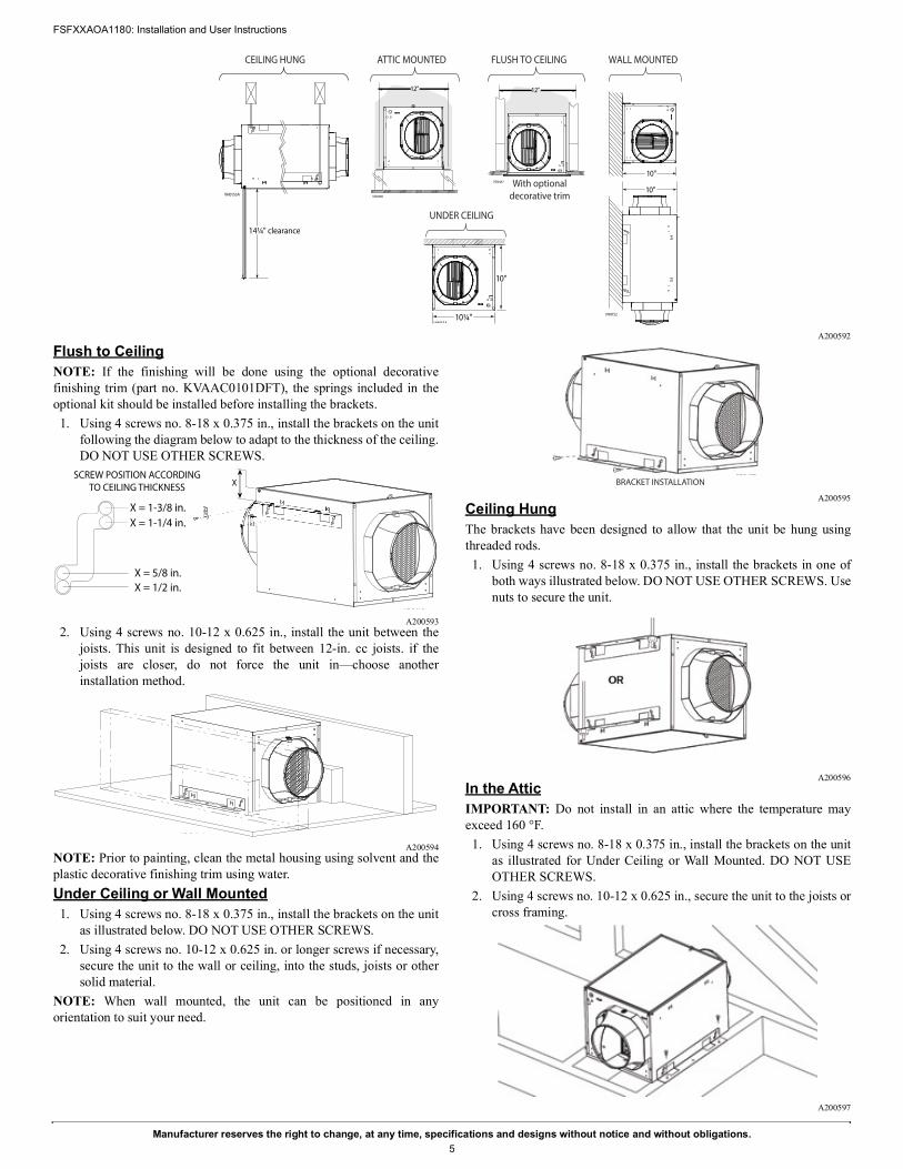
A200592
Flush to CeilingNOTE: If the finishing will be done using the optional decorativefinishing trim (part no. KVAAC0101DFT), the springs included in theoptional kit should be installed before installing the brackets.1. Using 4 screws no. 8-18 x 0.375 in., install the brackets on the unit
following the diagram below to adapt to the thickness of the ceiling.DO NOT USE OTHER SCREWS.
A2005932. Using 4 screws no. 10-12 x 0.625 in., install the unit between the
joists. This unit is designed to fit between 12-in. cc joists. if thejoists are closer, do not force the unit in—choose anotherinstallation method.
A200594NOTE: Prior to painting, clean the metal housing using solvent and theplastic decorative finishing trim using water.Under Ceiling or Wall Mounted1. Using 4 screws no. 8-18 x 0.375 in., install the brackets on the unit
as illustrated below. DO NOT USE OTHER SCREWS.2. Using 4 screws no. 10-12 x 0.625 in. or longer screws if necessary,
secure the unit to the wall or ceiling, into the studs, joists or othersolid material.
NOTE: When wall mounted, the unit can be positioned in anyorientation to suit your need.
A200595Ceiling HungThe brackets have been designed to allow that the unit be hung usingthreaded rods.1. Using 4 screws no. 8-18 x 0.375 in., install the brackets in one of
both ways illustrated below. DO NOT USE OTHER SCREWS. Usenuts to secure the unit.
A200596In the AtticIMPORTANT: Do not install in an attic where the temperature mayexceed 160 °F.1. Using 4 screws no. 8-18 x 0.375 in., install the brackets on the unit
as illustrated for Under Ceiling or Wall Mounted. DO NOT USEOTHER SCREWS.
2. Using 4 screws no. 10-12 x 0.625 in., secure the unit to the joists orcross framing.
A200597
With optionaldecorative trim
FLUSH TO CEILING
VD0467
12"
ATTIC MOUNTED
VD0466
12"
VH0152
10"
10"
WALL MOUNTED
UNDER CEILING
10¼"VH0154
10"
CEILING HUNG
VH0153A
14¼" clearance
X
VD0470
SCREW POSITION ACCORDINGTO CEILING THICKNESS
X = 1-3/8 in.X = 1-1/4 in.
X = 5/8 in.X = 1/2 in.
VD0471
BRACKET INSTALLATION

FSFXXAOA1180: Installation and User Instructions
Manufacturer reserves the right to change, at any time, specifications and designs without notice and without obligations.6
Connecting the Insulated Ducts to the Unit1. Slide the inner flexible duct over the port and tie it using a tie-wrap.2. Pull the insulation over the outer ring of the port without
compressing it.3. Use duct tape to seal the outer membrane of the insulated duct to
the outer ring of the port.IMPORTANT: Avoid blocking the test ports with the duct tape.
A200598NOTE: Make sure that the outdoor intake hood is easily accessible forannual maintenance. If located above the first floor, place it close to awindow or balcony to allow ease of access.
WARNING!PERSONAL INJURY HAZARDMake sure the outdoor intake hood is at least 12 inches above theground and 6 feet away from any of the following: Dryer exhaust,high-efficiency furnace vent, central vacuum vent, gas meter exhaust,gas barbecue-grill, any exhaust from a combustion source, garbage binand any other source of contamination.
WARNING!PERSONAL INJURY HAZARDFailure to follow this warning could result in personal injury or death.Never install a stale air exhaust register in a room where there is acombustion device, such as a gas furnace, a gas water heater or afireplace. A negative pressure could be created in the area of the fuelburning unit and draw carbon monoxide into the room. CO can causepersonal injury or death.

FSFXXAOA1180: Installation and User Instructions
Manufacturer reserves the right to change, at any time, specifications and designs without notice and without obligations.7
WIRING
Wiring and Logic Diagrams
A200601
WARNING!SHOCK HAZARDRisk of electric shock. Electrical wiring must be done by qualified personnel in accordance with all applicable codes and standards. Beforeconnecting wires, switch power off at service panel and lock service disconnecting means to prevent power from being switched on accidentally.
LOGIC DIAGRAM
WIRING DIAGRAM
Ref: 1103696_REV-AVE0450A
K1
M1
Power Supply(12V)
Line
Neutral
Low Voltage(24VAC)
K2
R
C
G
Gf
PTC
AC Line Filter
J1-2
J4-7
J4-6
J4-4
J4-5
F1
High Voltage(120VAC)
J1-1
To J10
J2-1
J2-2
Power Supply(3.3V)
MCUK1
K2
M2
StepperDriver
J5-1,2,3,4
WIRING COLOR CODE
BLK BLACKBLU BLUEGRN GREENORG ORANGE
PNK PINKRED REDWHT WHITEYEL YELLOW
Line voltage factory wiringLow voltage factory wiringLow voltage field wiring
BLK Supply fanmotorORG
BLURED
WHTPower cable
1
1
1
F1
J10
J2
J11 1
J7 J9
1
J5
BDM1
LED 1(low power)
LED 2(Status)
LED 3(120 VAC)
1
J419
M2
REDBLU
YELPNK
Damper Motor Harness
YWGfGRC
KVAAC0101DFT Wall
Control
)
Stb-outStb-in
LED
+24VAC Supply
AHU Wiring
Control cable
M1
GRN
A1
ELECTRONIC ASSEMBLY
RH SensorMode
no
Speed
120 VAC, 60 Hz
W1
GRNWHTBLK

FSFXXAOA1180: Installation and User Instructions
Manufacturer reserves the right to change, at any time, specifications and designs without notice and without obligations.8
Connection to the AHU
IMPORTANT: Control interface of AHU systems may vary. Please contact your AHU supplier for any installation involving alternate wiringelectrical specifications.
A200602
Connection to the Supply Fan Optional Wall Control
A200603
HOW TO TEST THE UNITAfter the unit has been installed, the low voltage connection has beenmade, and the ducts and hoods have been installed, the airflow can betested. To do so:1. Open the unit's door and take note of the unit's Run time % setting.2. If connected to the ducting of an AHU, turn the AHU OFF while
measuring the airflow.3. Turn the Run time % button in the "Test" position and close the
door.4. Wait until the booting sequence is done (at least 45 seconds).5. Remove the test port cap located on the port on the intake side of
the unit (closest to the filter).6. Test the airflow using a Pitot tube. The distance between the test
port and VD0472 the center of the duct is 3.75 inches.7. Put the cap back on the test port.8. Set the Run time % button back to its previous setting.
A200604
WARNING!SHOCK HAZARDRisk of electric shock. Electrical wiring must be done by qualified personnel in accordance with all applicable codes and standards. Beforeconnecting wires, switch power off at service panel and lock service disconnecting means to prevent power from being switched on accidentally.
Not synchronized: g
Y
W
GF
G
R
C
COMNC
NO
InternalLogic
Supply FanSystem
Y
W
G
R
C
Y W G R CThermostat
Optional Installation WiringSupply Fan Hard Connections
AHUJ4
Mandatory Installation Wiring
Synchronized: Start AHU blower when supply fan is running
Y
W
GF
G
R
C
COMNC
NO
InternalLogic
Supply FanSystem
J4
120VAC
24VAC Transformer
Line
Neutral
24VAC
Y
W
GF
G
R
C
COMNC
NO
InternalLogic
Supply FanSystem
Y
W
G
R
C
Y W G R CThermostat
AHUJ4

FSFXXAOA1180: Installation and User Instructions
Manufacturer reserves the right to change, at any time, specifications and designs without notice and without obligations.9
SERVICE PARTS
A200605
Replacement Parts and RepairIn order to ensure your ventilation unit remains in good working condition, you must use Factory Authorized Parts™ only. The Factory AuthorizedParts™ are specially designed for each unit and are manufactured to comply with all the applicable certification standards and maintain a high standardof safety. Any third party replacement part used may cause serious damage and drastically reduce the performance level of your unit, which will resultin premature failing. Contact your local dealer for all replacement parts and repairs.
Item no. Part no. Description
1 S97021043 Damper Assembly
2 S97021044 Motor Assembly
3 S97021045 Main Filter
4 S97021048 Electronic Cover
5 S97021047 Electronic Board
6 S97021041 6-in. Port
Not shown KVACN1010(C,B)SF Optional Supply Fan Wall Control
Not shown KVAAC0101DFT Optional Decorative Trim
Not shown S99010461 Optional MERV 8 Filter
Not shown S99010462 Optional MERV13 Filter
1
2
3
4
5
6
FSFXXAOA1180: Installation and User Instructions
Manufacturer reserves the right to change, at any time, specifications and designs without notice and without obligations.10
TROUBLESHOOTNG
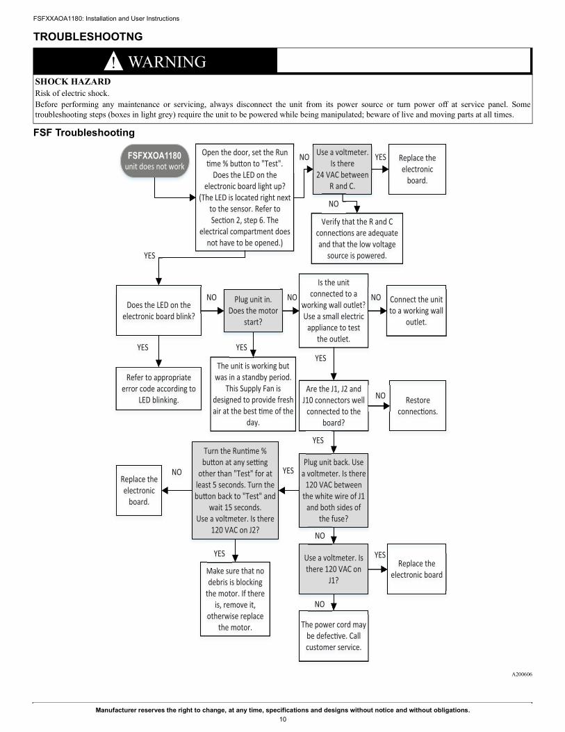
FSF Troubleshooting
A200606
WARNING!SHOCK HAZARDRisk of electric shock. Before performing any maintenance or servicing, always disconnect the unit from its power source or turn power off at service panel. Sometroubleshooting steps (boxes in light grey) require the unit to be powered while being manipulated; beware of live and moving parts at all times.
Open the door, set the Run �me % bu�on to "Test".
Does the LED on the electronic board light up?
(The LED is located right next to the sensor. Refer to Sec�on 2, step 6. The
electrical compartment does not have to be opened.)
Does the LED on the electronic board blink?
Refer to appropriate error code according to
LED blinking.
Plug unit in.Does the motor
start?
The unit is working but was in a standby period.
This Supply Fan is designed to provide fresh air at the best �me of the
day.
Is the unit connected to a
working wall outlet?Use a small electric
appliance to test the outlet.
Are the J1, J2 and J10 connectors well
connected to the board?
Plug unit back. Use a voltmeter. Is there
120 VAC between the white wire of J1
and both sides of the fuse?
Turn the Run�me % bu�on at any se�ng
other than "Test" for at least 5 seconds. Turn the bu�on back to "Test" and
wait 15 seconds.Use a voltmeter. Is there
120 VAC on J2?
Make sure that no debris is blocking
the motor. If there is, remove it,
otherwise replace the motor.
Replace the electronic
board.
Use a voltmeter. Is there 120 VAC on
J1?
The power cord may be defec�ve. Call customer service.
Replace the electronic board
Use a voltmeter. Is there
24 VAC between R and C.
Replace the electronic
board.
Verify that the R and C connec�ons are adequate and that the low voltage
source is powered.
unit does not work
YES
YES
NO
YES
NO Connect the unit to a working wall
outlet.
NO
YES
Restore connec�ons.
NO
YES
YES
NO
NO
YES
NO YES
NO
YES
NO
FSFXXOA1180

FSFXXAOA1180: Installation and User Instructions
Manufacturer reserves the right to change, at any time, specifications and designs without notice and without obligations.11
All Units Troubleshooting
A200608
LED Blinking CodesSensor Error 1 blinkDamper Error 2 blinksWall Control Error 4 blinksFilter Maintenance Slow blink (2 s ON, 2 s OFF)Learning Mode Very slow blink (1 s ON, 10 s OFF)
Sensor error1 blink
Replace the electronic board.
Damper error2 blinks
Perform a visual inspec�on. Is
there an obstacle
hindering damper
movement?
Are the damper wires in good
condi�on and well connected to the J5
connector on the electronic board?
Remove the obstacle. Restore power to the unit, note down
the Run�me % se�ng, and turn it to "Test". The damper should now work normally.
Put the Run �me % back to its previous value.
Restore the connec�ons or, if the wires are damaged,
replace the damper. Restore power to the unit, note down the Run �me % se�ng, and
turn it to "Test". The damper should now work normally.
Put the Run �me % back to its previous value.
Try connec�ng an other damper to the board (without completely installing it). Restore power to the unit, note down the Run�me % se�ng,
and turn it to "Test". If the damper does not move within 15 seconds, replace the electronic
board. If the damper now works, replace it.
Wall control error
4 blinks
There is a short circuit in the wall control wiring. Inspect wiring at the
wall control and on the terminal block. Restore any connec�on that
may be causing a short circuit. Is the problem fixed?
The wall control may be
damaged. Test using an other wall control.
Test the wall control using a
new wire. Is the problem
fixed?
Wall control does not work
Inspect the connec�ons at the control and at the
terminal block. Restore any wrong connec�on.
Is the problem fixed?
If there is no short, the wall control may
be damaged. Test using an other wall
control.
Test the wall control using a
new wire. Is the problem
fixed?
Learning modeVery slow blink
During the first 48 hours of opera�on, the unit is gathering environmental data.
This can be triggered by a change of se�ng, a power shortage, or powering unit back. This blinking code is not an error.
Unit does not provide the
required airflow
Are filter(s) grille, and/or hood
clogged?
Are the speed switches on the board properly posi�onned?
Is the measuring tool accurate? Try using a
different tool.
You are not sure that your ven�la�on
needs are met.
Review the Speed, Mode and Run�me % se�ngs.
Refer to Sec�on 3. Verify the W and Y
connec�ons.
YES
NO NO
YES
NO NO
NONO
Perform maintenance. Refer to Sec�on 3. Calibrate tool.
YES
NO
NO
YES
NO

FSFXXAOA1180: Installation and User Instructions
Manufacturer reserves the right to change, at any time, specifications and designs without notice and without obligations.12
APPENDIX A
A200609
VN0011A
Sele
cted
mod
eCl
imat
ic Z
ones
*1
- Ash
rae
2016
Zone
s 1-
42
- Ash
rae
2010
(fac
tory
set
ting)
Zone
s 1-
43
- IRC
/ IM
C 20
12-2
015
Zone
s 1-
4A
- Co
mfo
rt m
ode
Hot
/ H
umid
#1
Zone
s 2A
and
1
B -
Com
fort
mod
e H
ot /
Hum
id #
2Zo
nes
1 an
d 2A
C -
Com
fort
mod
e H
ot /
Dry
Zone
2B
D -
Com
fort
mod
e M
ixed
/ H
umid
Zone
s 3A
, 4A
, 3C
and
4C
E -
Com
fort
mod
e M
ixed
/ D
ryZo
nes
3B a
nd 4
B*N
ot re
com
men
ded
in a
ll ot
her z
ones

FSFXXAOA1180: Installation and User Instructions
Manufacturer reserves the right to change, at any time, specifications and designs without notice and without obligations.13
APPENDIX B
A200610

© 2020 Carrier. All rights reserved.A Carrier Company
Edition Date: 12/20 Catalog No: IM-FSF-01Replaces: New
FSFXXAOA1180: Installation and User Instructions
Manufacturer reserves the right to change, at any time, specifications and designs without notice and without obligations.14
NOTES PAGE