installation and user|mjs guide · sas connectivity-module specifications sas connectivity-module...
TRANSCRIPT

IBM BladeCenterSAS Connectivity Module
Installation and User's Guide
���

IBM BladeCenterSAS Connectivity Module
Installation and User's Guide
���

Note:
Before using this information and the product it supports, read the general information
in Appendix D, “IBM Statement of Limited Warranty Z125-4753-09 08/2006,” on page 81
and Appendix E, “Notices,” on page 103.
First Edition (September, 2007)
© Copyright International Business Machines Corporation 2007. All rights reserved.
US Government Users Restricted Rights – Use, duplication or disclosure restricted by
GSA ADP Schedule Contract with IBM Corp.

Contents
Safety . . . . . . . . . . . . . . . . . . . . . . . . vii
Chapter 1. Introduction . . . . . . . . . . . . . . . . . . 1
Features and specifications . . . . . . . . . . . . . . . . . . 2
Related documentation . . . . . . . . . . . . . . . . . . . 3
Option package contents . . . . . . . . . . . . . . . . . . 5
Notices and statements used in this document . . . . . . . . . . . 5
Major components of the connectivity module . . . . . . . . . . . 6
Chapter 2. Installing a connectivity module . . . . . . . . . . . 7
Installation guidelines . . . . . . . . . . . . . . . . . . . 8
System reliability considerations . . . . . . . . . . . . . . . 8
Handling static-sensitive devices . . . . . . . . . . . . . . . 9
Installing a connectivity module . . . . . . . . . . . . . . . 10
Chapter 3. Information panel LEDs and external ports . . . . . . . 11
Information panel . . . . . . . . . . . . . . . . . . . . 11
Information LEDs . . . . . . . . . . . . . . . . . . . . 12
Chapter 4. Managing the connectivity module using the Telnet interface 15
Enabling external ports . . . . . . . . . . . . . . . . . . 16
Enabling external management over all ports . . . . . . . . . . . 16
Configuring the date and time . . . . . . . . . . . . . . . . 16
Connecting to the connectivity module . . . . . . . . . . . . . 17
Establishing a Telnet session through the advanced management module 17
Establishing a Telnet session in a command-line screen . . . . . . . . 18
CLI command format . . . . . . . . . . . . . . . . . . . 18
Command-line interface guidelines . . . . . . . . . . . . . 19
Chapter 5. Managing the connectivity module using the embedded
Web-browser interface . . . . . . . . . . . . . . . . . 21
Enabling external ports . . . . . . . . . . . . . . . . . . 21
Enabling external management over all ports . . . . . . . . . . . 22
Configuring the date and time . . . . . . . . . . . . . . . . 22
Connecting to the connectivity module . . . . . . . . . . . . . 22
Establishing a Web-interface session through the advanced management
module . . . . . . . . . . . . . . . . . . . . . . . 23
Establishing a Web-interface session through a Web browser . . . . . . 24
Chapter 6. Managing the connectivity module using the advanced
Management Module interface . . . . . . . . . . . . . . 25
Enabling external ports . . . . . . . . . . . . . . . . . . 26
© Copyright IBM Corp. 2007 iii

Enabling external management over all ports . . . . . . . . . . . 26
Configuring the date and time . . . . . . . . . . . . . . . . 26
Establishing a Web-interface session . . . . . . . . . . . . . . 27
Activating a zone configuration . . . . . . . . . . . . . . . 27
Chapter 7. Managing the connectivity module using the Storage
Configuration Manager application . . . . . . . . . . . . . 31
Chapter 8. Configuring zones . . . . . . . . . . . . . . . . 33
User-defined zones . . . . . . . . . . . . . . . . . . . . 33
Planning a user-defined zone . . . . . . . . . . . . . . . 34
Planning considerations . . . . . . . . . . . . . . . . . 34
Predefined zones . . . . . . . . . . . . . . . . . . . . 35
Zone 5 (Predefined Config 01) . . . . . . . . . . . . . . . 36
Zone 6 (Predefined Config 02) . . . . . . . . . . . . . . . 36
Zone 7 (Predefined Config 03) . . . . . . . . . . . . . . . 37
Zone 8 (Predefined Config 04) . . . . . . . . . . . . . . . 37
Zone 9 (Predefined Config 05) . . . . . . . . . . . . . . . 38
Zone 10 (Predefined Config 06) . . . . . . . . . . . . . . . 39
Zone 11 (Predefined Config 07) . . . . . . . . . . . . . . . 40
Zone 12 (Predefined Config 08) . . . . . . . . . . . . . . . 41
Zone 13 (Predefined Config 09) . . . . . . . . . . . . . . . 42
Zoning configuration worksheet . . . . . . . . . . . . . . . 43
Appendix A. Using the CLI . . . . . . . . . . . . . . . . . 45
Command-line interface guidelines . . . . . . . . . . . . . . 45
CLI management commands . . . . . . . . . . . . . . . . 46
allregisters . . . . . . . . . . . . . . . . . . . . . . 46
clearlog . . . . . . . . . . . . . . . . . . . . . . . 46
clrerrorlog . . . . . . . . . . . . . . . . . . . . . . 46
comport . . . . . . . . . . . . . . . . . . . . . . 47
daemon . . . . . . . . . . . . . . . . . . . . . . 47
ecmregisters . . . . . . . . . . . . . . . . . . . . . 48
exit . . . . . . . . . . . . . . . . . . . . . . . . 48
fwcheck . . . . . . . . . . . . . . . . . . . . . . 48
fwdownload . . . . . . . . . . . . . . . . . . . . . 48
fwerase . . . . . . . . . . . . . . . . . . . . . . . 49
fwerasebackup . . . . . . . . . . . . . . . . . . . . 49
fwrollback . . . . . . . . . . . . . . . . . . . . . . 49
fwstoragedownload . . . . . . . . . . . . . . . . . . . 49
get_sensor . . . . . . . . . . . . . . . . . . . . . . 50
getsupport . . . . . . . . . . . . . . . . . . . . . . 50
ipconfig . . . . . . . . . . . . . . . . . . . . . . 50
linkerrorlog . . . . . . . . . . . . . . . . . . . . . 51
ntp . . . . . . . . . . . . . . . . . . . . . . . . 51
pcmerrorlog . . . . . . . . . . . . . . . . . . . . . 52
phy . . . . . . . . . . . . . . . . . . . . . . . . 52
iv Installation and User's Guide

phyattribute . . . . . . . . . . . . . . . . . . . . . 52
phyerrorlog . . . . . . . . . . . . . . . . . . . . . 53
phyregisters . . . . . . . . . . . . . . . . . . . . . 53
post_results . . . . . . . . . . . . . . . . . . . . . 53
printphystat . . . . . . . . . . . . . . . . . . . . . 53
reset . . . . . . . . . . . . . . . . . . . . . . . . 54
restoremfgdef . . . . . . . . . . . . . . . . . . . . . 54
sasaddr . . . . . . . . . . . . . . . . . . . . . . . 54
sasport . . . . . . . . . . . . . . . . . . . . . . . 55
sasport clrerrcnt . . . . . . . . . . . . . . . . . . . 55
sasport disable . . . . . . . . . . . . . . . . . . . 56
sasport enable . . . . . . . . . . . . . . . . . . . 56
sasport geterrcnt . . . . . . . . . . . . . . . . . . . 56
sasport reset . . . . . . . . . . . . . . . . . . . . 57
sasport status . . . . . . . . . . . . . . . . . . . . 57
sasport startlb . . . . . . . . . . . . . . . . . . . 58
sasport startsnoop . . . . . . . . . . . . . . . . . . 58
sasport stoplb . . . . . . . . . . . . . . . . . . . 58
sasport stopsnoop . . . . . . . . . . . . . . . . . . 58
setadminpassword . . . . . . . . . . . . . . . . . . . 59
smpregisters . . . . . . . . . . . . . . . . . . . . . 59
snmpcommunity . . . . . . . . . . . . . . . . . . . 60
snmpsyscontact . . . . . . . . . . . . . . . . . . . . 60
snmpsysdescr . . . . . . . . . . . . . . . . . . . . . 60
snmpsyslocation . . . . . . . . . . . . . . . . . . . . 61
snmptrapdest . . . . . . . . . . . . . . . . . . . . . 61
stat . . . . . . . . . . . . . . . . . . . . . . . . 61
target . . . . . . . . . . . . . . . . . . . . . . . 62
time . . . . . . . . . . . . . . . . . . . . . . . . 63
version . . . . . . . . . . . . . . . . . . . . . . . 63
xmlconnections . . . . . . . . . . . . . . . . . . . . 64
xmlevents . . . . . . . . . . . . . . . . . . . . . . 64
zoneconfig . . . . . . . . . . . . . . . . . . . . . . 64
zoneconfig apply . . . . . . . . . . . . . . . . . . 65
zoneconfig compare . . . . . . . . . . . . . . . . . 65
zoneconfig copy . . . . . . . . . . . . . . . . . . . 66
zoneconfig deny . . . . . . . . . . . . . . . . . . . 66
zoneconfig disable . . . . . . . . . . . . . . . . . . 66
zoneconfig erase . . . . . . . . . . . . . . . . . . . 67
zoneconfig get . . . . . . . . . . . . . . . . . . . 67
zoneconfig groupassign . . . . . . . . . . . . . . . . 67
zoneconfig permit . . . . . . . . . . . . . . . . . . 68
zoneconfig setdesc . . . . . . . . . . . . . . . . . . 68
zoneconfig setname . . . . . . . . . . . . . . . . . . 68
zoneconfig stat . . . . . . . . . . . . . . . . . . . 69
Appendix B. Using the embedded Web-browser interface . . . . . . 71
Contents v

Web-browser interface requirements . . . . . . . . . . . . . . 71
Logging into the Web-browser interface . . . . . . . . . . . . . 71
Monitoring the connectivity module . . . . . . . . . . . . . . 71
Updating firmware . . . . . . . . . . . . . . . . . . . . 73
Changing the password . . . . . . . . . . . . . . . . . . 73
Configuring zoning . . . . . . . . . . . . . . . . . . . . 73
Activating a zone working configuration . . . . . . . . . . . 73
Viewing a zone working configuration . . . . . . . . . . . . 74
Modifying a zone working configuration . . . . . . . . . . . 74
Appendix C. Getting help and technical assistance . . . . . . . . 77
Before you call . . . . . . . . . . . . . . . . . . . . . 77
Using the documentation . . . . . . . . . . . . . . . . . . 78
Getting help and information from the World Wide Web . . . . . . . 78
Software service and support . . . . . . . . . . . . . . . . 78
Hardware service and support . . . . . . . . . . . . . . . . 78
IBM Taiwan product service . . . . . . . . . . . . . . . . . 79
Appendix D. IBM Statement of Limited Warranty Z125-4753-09 08/2006 81
Part 1 - General Terms . . . . . . . . . . . . . . . . . . . 81
Part 2 - Country-unique Terms . . . . . . . . . . . . . . . . 86
Part 3 - Warranty Information . . . . . . . . . . . . . . . . 98
Appendix E. Notices . . . . . . . . . . . . . . . . . . 103
Trademarks . . . . . . . . . . . . . . . . . . . . . . 104
Important notes . . . . . . . . . . . . . . . . . . . . 105
Product recycling and disposal . . . . . . . . . . . . . . . 105
Battery return program . . . . . . . . . . . . . . . . . . 107
Electronic emission notices . . . . . . . . . . . . . . . . . 109
Federal Communications Commission (FCC) statement . . . . . . 109
Industry Canada Class A emission compliance statement . . . . . . 109
Australia and New Zealand Class A statement . . . . . . . . . 110
United Kingdom telecommunications safety requirement . . . . . . 110
European Union EMC Directive conformance statement . . . . . . 110
Taiwanese Class A warning statement . . . . . . . . . . . . 111
Chinese Class A warning statement . . . . . . . . . . . . . 111
Japanese Voluntary Control Council for Interference (VCCI) statement 111
Index . . . . . . . . . . . . . . . . . . . . . . . . 113
vi Installation and User's Guide

Safety
Before installing this product, read the Safety Information.
Antes de instalar este produto, leia as Informações de Segurança.
Pred instalací tohoto produktu si prectete prírucku bezpecnostních instrukcí.
Læs sikkerhedsforskrifterne, før du installerer dette produkt.
Lees voordat u dit product installeert eerst de veiligheidsvoorschriften.
Ennen kuin asennat tämän tuotteen, lue turvaohjeet kohdasta Safety
Information.
Avant d’installer ce produit, lisez les consignes de sécurité.
Vor der Installation dieses Produkts die Sicherheitshinweise lesen.
Prima di installare questo prodotto, leggere le Informazioni sulla Sicurezza.
Les sikkerhetsinformasjonen (Safety Information) før du installerer dette
produktet.
© Copyright IBM Corp. 2007 vii

Antes de instalar este produto, leia as Informações sobre Segurança.
Antes de instalar este producto, lea la información de seguridad.
Läs säkerhetsinformationen innan du installerar den här produkten.
viii Installation and User's Guide

Statement 1:
DANGER
Electrical current from power, telephone, and communication cables is
hazardous.
To avoid a shock hazard:
v Do not connect or disconnect any cables or perform installation,
maintenance, or reconfiguration of this product during an electrical
storm.
v Connect all power cords to a properly wired and grounded electrical
outlet.
v Connect to properly wired outlets any equipment that will be attached
to this product.
v When possible, use one hand only to connect or disconnect signal
cables.
v Never turn on any equipment when there is evidence of fire, water, or
structural damage.
v Disconnect the attached power cords, telecommunications systems,
networks, and modems before you open the device covers, unless
instructed otherwise in the installation and configuration procedures.
Statement 2:
CAUTION:
When replacing the lithium battery, use only IBM Part Number 33F8354 or
an equivalent type battery recommended by the manufacturer. If your
system has a module containing a lithium battery, replace it only with the
same module type made by the same manufacturer. The battery contains
lithium and can explode if not properly used, handled, or disposed of.
Do not:
v Throw or immerse into water
v Heat to more than 100º C (212º F)
v Repair or disassemble
Safety ix

Dispose of the battery as required by local ordinances or regulations.
Statement 21:
CAUTION:
Hazardous energy is present when the blade server is connected to the
power source. Always replace the blade server-cover before installing the
blade server.
x Installation and User's Guide

Chapter 1. Introduction
This Installation and User’s Guide contains instructions for installing your SAS
Connectivity Module for IBM® BladeCenter® products in a BladeCenter unit.
This Installation and User’s Guide also contains information about configuring
and managing the Serial Attached SCSI (small computer system interface)
(SAS) connectivity module.
The SAS connectivity module provides a connection to I/O-module bay 3 and
I/O-module bay 4 in the BladeCenter units. Each SAS connectivity module (up
to two) is supported by a SAS expansion card in the BladeCenter unit. You
must install a SAS expansion card for operation with each SAS connectivity
module. For more information about the SAS expansion card, see the SAS
Expansion Card Installation and User's Guide provided in the Documentation
directory on the Support CD or at http://www.ibm.com/systems/support/.
For additional information about other BladeCenter components, see the
instructions in your BladeCenter documentation.
Notes:
v Except where specifically stated otherwise in this document, the term
connectivity module refers to the SAS connectivity module for IBM
BladeCenter products.
v Except where specifically stated otherwise in this document, the IBM
BladeCenter unit (for example, the BladeCenter Type 8677) is referred to as
the BladeCenter unit.
v Throughout this document, the user name is also known as the login name,
user identifier, or user ID for logging into one or more of the following
interfaces or programs:
– Telnet interface
– Web-browser interface
– Advanced Management Module Web-interface
– Storage Configuration Manager application
v You can install up to two connectivity modules in a BladeCenter unit.
You can obtain up-to-date information about the connectivity module and
other IBM products at http://www.ibm.com/systems/support/.
The connectivity module has six labels: a safety certification label, a Common
Language Equipment Identification (CLEI) label, a product name label, a serial
number label, a media access control (MAC) address label, and a SAS ID and
MAC address label.
© Copyright IBM Corp. 2007 1

See “Major components of the connectivity module” on page 6 for an
illustration that shows the location of the connectivity-module labels. You will
need this information when you register the connectivity module with IBM.
Record your product information in this table
Product name: ____ SAS Connectivity Module
Chassis serial number: __________________________________________________
For example: 11S32R1793ZJ1ZC846H073
Media access control (MAC) address: ______________________________________
SAS ID: ______________________________________
After you install the connectivity module, you can manage and configure it
using any one of the following interfaces:
v A Telnet connection to the embedded command-line interface (CLI)
For additional information, see Chapter 4, “Managing the connectivity
module using the Telnet interface,” on page 15.
v A Web-browser interface
For additional information, see Chapter 5, “Managing the connectivity
module using the embedded Web-browser interface,” on page 21.
v The Advanced Management Module Web-interface
For additional information, see Chapter 6, “Managing the connectivity
module using the advanced Management Module interface,” on page 25.
v The Storage Configuration Manager application
For additional information, see Chapter 7, “Managing the connectivity
module using the Storage Configuration Manager application,” on page 31.
Features and specifications
This section provides a summary of the features and specifications for the
connectivity module.
The connectivity module supports the following features:
v Serial SCSI Protocol (SSP)
v Serial Management Protocol (SMP) as defined in the SAS specification
v Fourteen internal x1 links to blade servers
v Four external x4 links for storage servers
v Link error detection
Table 1 on page 3 contains a summary of the specifications of the connectivity
module.
2 Installation and User's Guide

Table 1. SAS connectivity-module specifications
SAS connectivity-module
features:
v SAS expander
v Vitesse 7157
Environmental:
v Temperature and altitude:
– Operating:
- 10°C to 52°C
(50°F to 126°F) at an
altitude of
0 to 914 m
(0 to 2 998 ft)
- 10°C to 49°C
(50°F to 120°F) at an
altitude of
0 to 3 000 m
(0 to 9 843 ft)
– Non-operating:
-40°C to 65°C
(-40°F to 149°F) at an
altitude of
0 to 12 000 m
(0 to 39 370 ft)
v Humidity:
– Operating: 8% to 80%,
noncondensing
– Non-operating: 5% to
80%, noncondensing
SAS connectivity-module
maintainability:
v Diagnostics: Power-on
self-test (POST) is
performed on all
functional components.
Port operational tests
include internal, external,
and online tests.
v User interface:
Light-emitting diode
(LED) indicators
Fabric management:
v Management methods:
– Telnet and command
line interface (CLI)
– Web-browser interface
– Advanced
Management Module
Web-interface
– Storage Configuration
Manager interface
v SAS connectivity module
simple network
management protocol
(SNMP) agent: Enables a
network management
workstation to receive
configuration values and
SAS link data through
SNMP and the Ethernet
interface.
Dimensions:
v Width: 112 mm (4.41 in.)
v Height: 29 mm (1.14 in.)
v Depth: 260 mm (10.25
in.)
v Weight: 2 lb (.91 kg)
SAS connectivity-module
regulatory certifications:
Electrical:
v Power source loading: 2
amps maximum at 12 V
dc
v Heat output: 20 watts
maximum
v Operating voltage:
12 V dc
v Circuit protection:
Internally fused
Related documentation
This Installation Guide contains installation and setup instructions for the
connectivity module. This document also provides general information about
the connectivity module, including how to configure the connectivity module
and how to access and use online help.
This Installation Guide is provided in Portable Document Format (PDF) on the
Support CD that came with your connectivity module. For additional
information about the Support CD, see “Option package contents” on page 5.
Chapter 1. Introduction 3

Additional related documentation might be included on the Support CD or
available on the IBM support Web site, http://www.ibm.com/systems/support/.
The following related documentation is available at http://www.ibm.com/systems/support/:
v IBM BladeCenter Installation and User’s Guide contains setup and installation
instructions for your BladeCenter unit, including information about getting
started and how to install a blade server.
v IBM BladeCenter blade server Installation and User’s Guides
Each type of blade server has a customized Installation and User’s Guide that
is provided in PDF on the IBM BladeCenter Documentation CD and at
http://www.ibm.com/systems/support/.
v SAS Expansion Card (CFFv) Installation and User's Guide for IBM BladeCenter
products contains installation instructions for the SAS expansion card. It also
contains information about using the LSI Logic Configuration Utility
program to configure the SAS expansion card.
v Multilingual Safety Information
This multilingual document is provided in PDF on the IBM BladeCenter
Documentation CD and at http://www.ibm.com/systems/support/. It
contains translated versions of the caution and danger statements that
appear in the documentation for your blade server. Each caution and danger
statement has an assigned number, which you can use to locate the
corresponding statement in your native language.
v Rack Installation Instructions
This document contains the instructions to install your BladeCenter unit in a
rack.
v IBM BladeCenter Hardware Maintenance Manual and Troubleshooting Guide or
Problem Determination and Service Guide
Depending on your BladeCenter type, one of these documents is provided in
PDF on the IBM BladeCenter Documentation CD and at http://www.ibm.com/systems/support/. It contains information to help you solve
BladeCenter problems yourself or to provide helpful information to a service
technician.
Depending on your blade-server model, additional documents might be
included on the IBM BladeCenter Documentation CD, with the most recent
versions of all BladeCenter documents available at http://www.ibm.com/systems/bladecenter/.
In addition to reviewing the documentation in this library, make sure that you
review the IBM Planning and Installation Guide for your BladeCenter unit to
help you prepare for system installation and configuration. For more
information see http://www.ibm.com/systems/support/.
4 Installation and User's Guide

Option package contents
The connectivity-module option package contains the following items:
v One SAS connectivity module
v The SAS Connectivity Module Getting Started Guide
v The Support CD, which includes:
– The SAS connectivity module and SAS expansion card Installation and
User’s Guide
– The SAS connectivity module and SAS expansion card Getting Started
Guide
– IBM BladeCenter Storage Configuration Manager Planning, Installation, and
Configuration Guide
– SAS expansion card applications
– MIB files
– Readme file
– Multilingual Safety Information
For the latest up-to-date Readme file, see http://www.ibm.com/systems/support/.
Note: The Support CD might contain additional information. Use the
subdirectories to help you find information quickly.
Notices and statements used in this document
The caution and danger statements used in this document are also in the
multilingual Safety Information document, which is on the Support CD. Each
statement is numbered for reference to the corresponding statement in the
multilingual Safety Information document.
Chapter 1. Introduction 5

The following notices and statements are used in this document:
v Note: These notices provide important tips, guidance, or advice.
v Important: These notices provide information or advice that might help you
avoid inconvenient or problem situations.
v Attention: These notices indicate potential damage to programs, devices, or
data. An attention notice is placed just before the instruction or situation in
which damage could occur.
v Caution: These statements indicate situations that can be potentially
hazardous to you. A caution statement is placed just before the description
of a potentially hazardous procedure step or situation.
v Danger: These statements indicate situations that can be potentially lethal or
extremely hazardous to you. A danger statement is placed just before the
description of a potentially lethal or extremely hazardous procedure step or
situation.
Major components of the connectivity module
The following illustration shows the major components of the connectivity
module. Your hardware might have labels not shown in the following
illustration.
For more information about the components of the information panel, see
Chapter 3, “Information panel LEDs and external ports,” on page 11.
Product name label
Releaselever
SAS connectivity module
Serial number label
Media access control(MAC) addressand SAS ID label
Safety certification label
Connectorports
Online and error LEDs
OK and error LEDs
CLEI label
6 Installation and User's Guide

Chapter 2. Installing a connectivity module
This chapter provides instructions for installing a connectivity module in a
BladeCenter unit.
Note: The BladeCenter unit shown in the illustrations in this document might
be different from your BladeCenter unit. For additional information, see
the documentation that came with your BladeCenter unit.
You must install connectivity modules only in BladeCenter I/O-module bay 3
and I/O-module bay 4 of the following supported BladeCenter units:
v BladeCenter Type 8677
v BladeCenter Types 8720 and 8730
v BladeCenter Type 8750
v BladeCenter Type 8852
v BladeCenter Type 8886
Installing a connectivity module in I/O-module bay 3 or I/O-module bay 4
provides connectivity to the SAS expansion card(s) installed in the blade
servers in your BladeCenter unit. Installing two connectivity modules allows
you to have two connections to the SAS expansion cards installed in the blade
servers.
Important: The connectivity modules in I/O-module bay 3 and I/O-module
bay 4 and all expansion cards in the BladeCenter unit must use the same
interface type. Therefore, you must install SAS expansion cards before you
install connectivity modules in the blade servers in your BladeCenter unit. For
more information about the SAS expansion card, see the Installation and User's
Guide for the SAS expansion card located in the Documentation directory on the
Support CD or at http://www.ibm.com/systems/support/.
The following table summarizes the connectivity-module connections to the
SAS expansion card ports.
I/O
Module
Bay Connectivity-module function
3 Port 0 connection
4 Port 1 connection
© Copyright IBM Corp. 2007 7

Installation guidelines
Before you install the connectivity module in the BladeCenter unit, read the
following information:
v Read the safety information beginning on page vii and the guidelines in
“Handling static-sensitive devices” on page 9. This information will help
you work safely with the blade server, BladeCenter unit, and options.
v Observe good housekeeping in the area where you are working. Place
removed covers and other parts in a safe place.
v You do not have to turn off the BladeCenter unit to install or replace any of
the hot-swap modules on the rear of the BladeCenter unit.
v Blue on a component indicates touch points, where you can grip the
component to remove it from or install it in the blade server, or open or
close a latch.
v Orange on a component or an orange label on or near a component indicates
that the component can be hot-swapped, which means that you can remove
or install the component while the BladeCenter unit is running. (Orange can
also indicate touch points on hot-swap components.) See the instructions for
removing or installing a specific hot-swap component for any additional
procedures that you might have to perform before you remove or install the
component.
v When you are finished working on the BladeCenter unit, reinstall all safety
shields, guards, labels, and ground wires.
v For a list of supported options for the BladeCenter unit, see
http://www.ibm.com/servers/eserver/serverproven/compat/us/.
System reliability considerations
Attention: To help ensure proper cooling and system reliability, make sure
that:
v Each of the module bays on the rear of the BladeCenter unit has either a
module or filler module installed.
v A removed hot-swap module is replaced with an identical module or filler
module as soon as possible.
8 Installation and User's Guide
Handling static-sensitive devices
Attention: Static electricity can damage electronic devices, including your
blade server. To avoid damage, keep static-sensitive devices in their
static-protective packages until you are ready to install them.
To reduce the possibility of damage from electrostatic discharge, observe the
following precautions:
v When you work on a BladeCenter unit that has an electrostatic discharge
(ESD) connector, use a wrist strap when you handle modules, optional
devices, or blade servers. To work correctly, the wrist strap must have a
good contact on both ends (touching your skin at one end and firmly
connected to the ESD connector on the front or back of the BladeCenter
unit).
v Limit your movement. Movement can cause static electricity to build up
around you.
v Handle the device carefully, holding it by its edges or its frame.
v Do not touch solder joints, pins, or exposed circuitry.
v Do not leave the device where others can handle and damage it.
v While the device is still in its static-protective package, touch it to any
unpainted metal surface of the BladeCenter unit or any unpainted metal
surface on any other grounded component in the rack you are installing the
device in for at least 2 seconds. (This drains static electricity from the
package and from your body.)
v Remove the device from its package and install it directly into the blade
server without setting down the device. If it is necessary to set down the
device, place it back into its static-protective package. Do not place the
device on your blade server cover or on a metal surface.
v Take additional care when handling devices during cold weather. Heating
reduces indoor humidity and increases static electricity.
Chapter 2. Installing a connectivity module 9

Installing a connectivity module
For information about installing an I/O module into a BladeCenter unit, see
the Installation and User's Guide that came with your BladeCenter unit. The
following illustration shows a vertical orientation for installing a connectivity
module in the BladeCenter unit. The illustrations in this document might differ
slightly from your hardware.
Note: For additional information about installing an connectivity module in
other types of BladeCenter units, see the documentation that came with
your BladeCenter unit.
BladeCenterunit
LatchReleaselever
SAS connectivitymodule
Figure 1. Installing the connectivity module into a BladeCenter unit
10 Installation and User's Guide
Chapter 3. Information panel LEDs and external ports
This chapter describes the information LEDs (also known as indicators) on the
connectivity module and identifies the connectivity module external ports.
Note: The illustrations in this document might differ slightly from your
hardware.
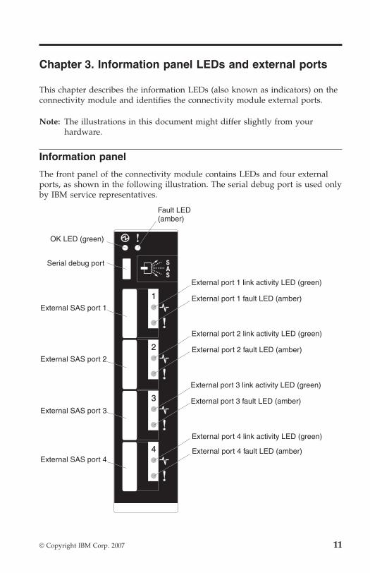
Information panel
The front panel of the connectivity module contains LEDs and four external
ports, as shown in the following illustration. The serial debug port is used only
by IBM service representatives.
Fault LED(amber)
OK LED (green)
Serial debug port
External SAS port 1
External SAS port 2
External SAS port 3
External SAS port 4
1
2
3
4
External port 2 fault LED (amber)
External port 2 link activity LED (green)
External port 1 fault LED (amber)
External port 3 fault LED (amber)
External port 4 fault LED (amber)
External port 1 link activity LED (green)
External port 3 link activity LED (green)
External port 4 link activity LED (green)
© Copyright IBM Corp. 2007 11
The connectivity module contains:
v LEDs that display the status of the connectivity module and its network
connections. For the activity description of each LED, see “Information
LEDs”).
v Four external SAS ports to connect devices, end devices, and servers. These
external ports are identified as ports 1, 2, 3, and 4 in the
connectivity-module configuration menus and are labeled 1, 2, 3, and 4
(from top to bottom) on the connectivity module.
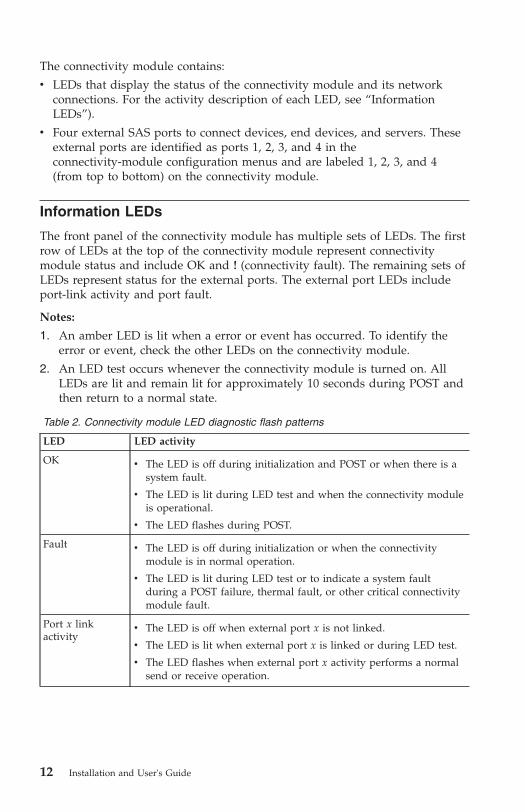
Information LEDs
The front panel of the connectivity module has multiple sets of LEDs. The first
row of LEDs at the top of the connectivity module represent connectivity
module status and include OK and ! (connectivity fault). The remaining sets of
LEDs represent status for the external ports. The external port LEDs include
port-link activity and port fault.
Notes:
1. An amber LED is lit when a error or event has occurred. To identify the
error or event, check the other LEDs on the connectivity module.
2. An LED test occurs whenever the connectivity module is turned on. All
LEDs are lit and remain lit for approximately 10 seconds during POST and
then return to a normal state.
Table 2. Connectivity module LED diagnostic flash patterns
LED LED activity
OK
v The LED is off during initialization and POST or when there is a
system fault.
v The LED is lit during LED test and when the connectivity module
is operational.
v The LED flashes during POST.
Fault
v The LED is off during initialization or when the connectivity
module is in normal operation.
v The LED is lit during LED test or to indicate a system fault
during a POST failure, thermal fault, or other critical connectivity
module fault.
Port x link
activity
v The LED is off when external port x is not linked.
v The LED is lit when external port x is linked or during LED test.
v The LED flashes when external port x activity performs a normal
send or receive operation.
12 Installation and User's Guide
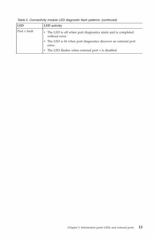
Table 2. Connectivity module LED diagnostic flash patterns (continued)
LED LED activity
Port x fault
v The LED is off when port diagnostics starts and is completed
without error.
v The LED is lit when port diagnostics discover an external port
error.
v The LED flashes when external port x is disabled.
Chapter 3. Information panel LEDs and external ports 13

14 Installation and User's Guide

Chapter 4. Managing the connectivity module using the
Telnet interface
The connectivity module contains a Telnet server. This server allows a Telnet
client to establish a Telnet session with the connectivity module to retrieve
information or to configure settings using the CLI interface. You can perform a
variety of fabric and connectivity-management tasks through an Ethernet
connection using the CLI interface.
You can access the Telnet interface in one of two ways:
v Advanced Management Module Web-interface
v CLI on a network management workstation
Notes:
1. To access a connectivity module from a network management workstation,
make sure that it is connected to an external advanced management
module-Ethernet port. If you are using a gateway to communicate with the
BladeCenter unit, set the gateway IP address for the connectivity module to
the IP address of the advanced management module.
2. To access and manage the connectivity module from an external
environment, you have to enable external ports, external management over
all ports, and set the date and time.
3. The sample screens and windows that appear in this document might differ
slightly from the screens and windows that are displayed by your system.
Screen and window content varies based on the type of BladeCenter unit
that you are using and the options that are installed.
Important: The connectivity module is exclusively supported by the advanced
management module. Before you configure the connectivity module, make sure
that the advanced management modules in your BladeCenter unit are correctly
configured. For more information about the advanced management module,
see the User's Guide that came with your advanced management module and
at http://www.ibm.com/systems/support/.
In addition to reviewing the documentation that is described in “Related
documentation” on page 3, make sure that you review the IBM Planning and
Installation Guide for your BladeCenter unit at http://www.ibm.com/systems/support/ for information to help you prepare for system installation and
configuration.
© Copyright IBM Corp. 2007 15

To configure the connectivity module through the Telnet interface, the Internet
protocol (IP) address and subnet masks must be compatible, and the following
configuration settings for the advanced management module must be enabled:
v External ports
v External management over all ports
v Date and time
Enabling external ports
To enable the external ports on the advanced management module, complete
the following steps:
1. In the advanced Management Module Web-interface, click I/O Module
Tasks > Admin/Power/Reset. The I/O Module Power/Restart window
opens.
2. In the I/O Module Advanced Setup section, select an external port to
change its port access setting to Enabled, and click Save.
Enabling external management over all ports
To enable the external management over all ports setting, complete the
following steps:
1. In the advanced Management Module Web-interface, click I/O Module
Tasks > Configuration. The I/O Module Configuration window opens.
2. Click the blade-server bay number whose setting you want to enable. The
Current IP Configuration window for the selected blade-server bay opens.
3. Click Advanced Configuration. The Advanced Configuration I/O Module
x window opens. Where x is the blade-server bay number.
4. In the Advanced Setup section, select the port to change its external
management over all ports setting to Enabled, and click Save.
Configuring the date and time
Change the date and time of the advanced management module using the CLI
time command. At the CLI prompt, type time and press Enter.
For example, the format for June 28, 2004 8:46 P.M. (Monday) is:
>time set 6 28 2004 20 46 0 1
For detailed information about using time and additional CLI commands, see
Appendix A, “Using the CLI,” on page 45.
16 Installation and User's Guide
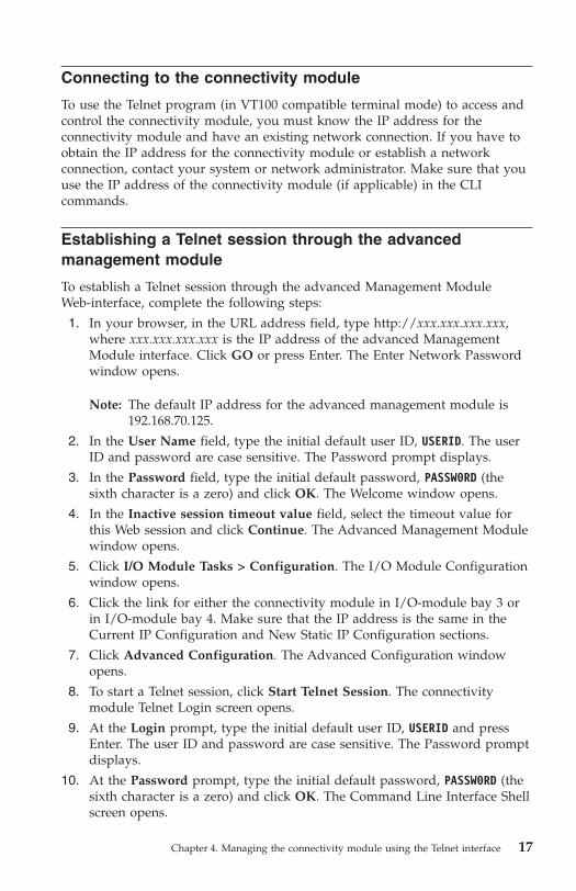
Connecting to the connectivity module
To use the Telnet program (in VT100 compatible terminal mode) to access and
control the connectivity module, you must know the IP address for the
connectivity module and have an existing network connection. If you have to
obtain the IP address for the connectivity module or establish a network
connection, contact your system or network administrator. Make sure that you
use the IP address of the connectivity module (if applicable) in the CLI
commands.
Establishing a Telnet session through the advanced
management module
To establish a Telnet session through the advanced Management Module
Web-interface, complete the following steps:
1. In your browser, in the URL address field, type http://xxx.xxx.xxx.xxx,
where xxx.xxx.xxx.xxx is the IP address of the advanced Management
Module interface. Click GO or press Enter. The Enter Network Password
window opens.
Note: The default IP address for the advanced management module is
192.168.70.125.
2. In the User Name field, type the initial default user ID, USERID. The user
ID and password are case sensitive. The Password prompt displays.
3. In the Password field, type the initial default password, PASSW0RD (the
sixth character is a zero) and click OK. The Welcome window opens.
4. In the Inactive session timeout value field, select the timeout value for
this Web session and click Continue. The Advanced Management Module
window opens.
5. Click I/O Module Tasks > Configuration. The I/O Module Configuration
window opens.
6. Click the link for either the connectivity module in I/O-module bay 3 or
in I/O-module bay 4. Make sure that the IP address is the same in the
Current IP Configuration and New Static IP Configuration sections.
7. Click Advanced Configuration. The Advanced Configuration window
opens.
8. To start a Telnet session, click Start Telnet Session. The connectivity
module Telnet Login screen opens.
9. At the Login prompt, type the initial default user ID, USERID and press
Enter. The user ID and password are case sensitive. The Password prompt
displays.
10. At the Password prompt, type the initial default password, PASSW0RD (the
sixth character is a zero) and click OK. The Command Line Interface Shell
screen opens.
Chapter 4. Managing the connectivity module using the Telnet interface 17

Note: To open online help, type help and press Enter.
For more information about using the CLI, see Appendix A, “Using the CLI,”
on page 45.
Establishing a Telnet session in a command-line screen
You can access the connectivity module using IP-enabled devices that are
connected to the advanced management module. An Ethernet connection to the
advanced management-module external port on the BladeCenter unit is
required. For more information, see the following documents at
http://www.ibm.com/systems/support/:
v BladeCenter unit Installation and User’s Guide
v IBM BladeCenter Advanced Management Module Installation Guide
v IBM BladeCenter Management Module User’s Guide
To establish a Telnet session through the CLI, complete the following steps:
Note: The IP addresses in the following step are the default IP address of the
connectivity modules; if new IP addresses have been assigned to the
connectivity modules, use these instead.
1. Open the CLI on the network management workstation, type one of the
following commands, and press Enter.
v For the connectivity module in I/O-module bay 3:
>telnet 192.168.70.129
v For the connectivity module in I/O-module bay 4:
>telnet 192.168.70.130
A command prompt screen opens.
2. At the Login prompt, type the initial default user ID, USERID and press
Enter. The user ID and password are case sensitive. The Password prompt
displays.
3. At the Password prompt, type the initial default password, PASSW0RD (the
sixth character is a zero) and press Enter. The Command Line Interface
Shell screen opens.
CLI command format
The information in this section gives an overview of the CLI-command format.
For detailed information about using CLI commands, see Appendix A, “Using
the CLI,” on page 45.
18 Installation and User's Guide
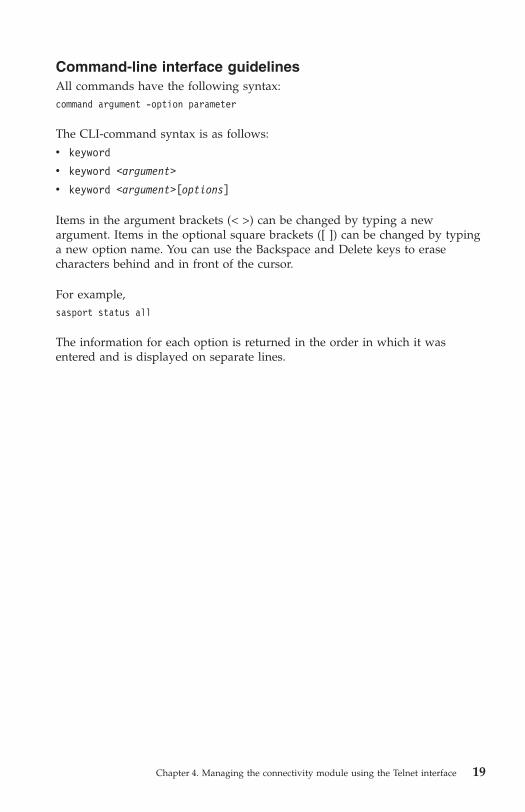
Command-line interface guidelines
All commands have the following syntax:
command argument -option parameter
The CLI-command syntax is as follows:
v keyword
v keyword <argument>
v keyword <argument>[options]
Items in the argument brackets (< >) can be changed by typing a new
argument. Items in the optional square brackets ([ ]) can be changed by typing
a new option name. You can use the Backspace and Delete keys to erase
characters behind and in front of the cursor.
For example,
sasport status all
The information for each option is returned in the order in which it was
entered and is displayed on separate lines.
Chapter 4. Managing the connectivity module using the Telnet interface 19

20 Installation and User's Guide

Chapter 5. Managing the connectivity module using the
embedded Web-browser interface
The connectivity module contains an embedded Web-browser interface. This
allows a Web-based client to establish a Web-interface session with the
connectivity module to retrieve information using a Web browser.
You can access the Web-browser interface in one of two ways:
v Advanced Management Module Web-interface
v Web browser on a network management workstation
The embedded Web-browser interface is a graphical user interface that requires
a Web browser to view and manage the connectivity module. For information
about system requirements and supported Web browsers, see Appendix B,
“Using the embedded Web-browser interface,” on page 71.
Important: The connectivity module is exclusively supported by the advanced
management module. Before you configure the connectivity module, make sure
that the advanced management modules in your BladeCenter unit are correctly
configured. For more information about the advanced management module,
see the User's Guide that came with your advanced management module and
at http://www.ibm.com/systems/support/.
In addition to reviewing the documentation that is described in “Related
documentation” on page 3, make sure that you review the IBM Planning and
Installation Guide for your BladeCenter unit at http://www.ibm.com/systems/support/ for information to help you prepare for system installation and
configuration.
Note: The sample screens and windows that appear in this document might
differ slightly from the screens and windows that are displayed by your
system. Screen and window content varies based on the type of
BladeCenter unit that you are using and the options that are installed.
Enabling external ports
To configure the connectivity module through the embedded Web-browser
interface, the IP address and subnet masks must be compatible, and the
following configuration settings in the advanced management module must be
enabled:
v External ports
v External management over all ports
v Date and time
© Copyright IBM Corp. 2007 21

Note: To access a connectivity module from a network management
workstation, make sure that it is connected to an external advanced
management module-Ethernet port. If you are using a gateway to
communicate with the BladeCenter unit, set the gateway IP address for
the connectivity module to the IP address of the advanced management
module.
To enable the external port, complete the following steps:
1. In the advanced Management Module Web-interface, click I/O Module
Tasks > Admin/Power/Reset. The I/O Module Power/Restart window
opens.
2. In the I/O Module Advanced Setup section, select an external port to
change its port access setting to Enabled, and click Save.
Enabling external management over all ports
To enable the external management over all ports setting, complete the
following steps:
1. In the advanced Management Module Web-interface, click I/O Module
Tasks > Configuration. The I/O Module Configuration window opens.
2. Click the blade-server bay number whose setting you want to enable. The
Current IP Configuration window for the selected blade-server bay opens.
3. Click Advanced Configuration. The Advanced Configuration I/O Module
x window opens. Where x is the blade-server bay number.
4. In the Advanced Setup section, select the port to change its external
management over all ports setting to Enabled, and click Save.
Configuring the date and time
Change the date and time of the connectivity module using the CLI time
command. At the prompt, type time and press Enter.
For example, the format for June 28, 2004 8:46 P.M. (Monday) is:
>time set 6 28 2004 20 46 0 1
For detailed information about using the time and additional CLI commands,
see Appendix A, “Using the CLI,” on page 45.
Connecting to the connectivity module
To use the embedded Web-browser interface to access and control the
connectivity module, you must know the IP address for the connectivity
module and have an existing network connection. If you have to obtain the IP
address for the connectivity module or establish a network connection, contact
your system or network administrator.
22 Installation and User's Guide

Establishing a Web-interface session through the advanced
management module
To establish a Web-interface session through the advanced management
module, complete the following steps:
1. In your browser, in the URL address field, type http://xxx.xxx.xxx.xxx,
where xxx.xxx.xxx.xxx is the IP address of the advanced Management
Module interface. Click GO or press Enter. The Enter Network Password
window opens.
Note: The default IP address for the advanced management module is
192.168.70.125.
2. In the User Name field, type the initial default user name, USERID. The
user name and password are case sensitive.
3. In the Password field, type the initial default password, PASSW0RD (the
sixth character is a zero) and click OK. The Welcome window opens.
4. In the Inactive session timeout value field, select the timeout value for
this Web session and click Continue. The BladeCenter Advanced
Management Module window opens.
5. Click I/O Module Tasks > Configuration. The I/O Module Configuration
window opens.
6. Click the link for either the connectivity module in I/O-module bay 3 or
in I/O-module bay 4. Make sure that the IP address is the same in the
Current IP Configuration and New Static IP Configuration sections.
7. Click Advanced Configuration. The Advanced Configuration I/O Module
x window opens. Where x is the blade-server bay number.
8. In the Start Telnet/Web Session section, click Start Web Session.
9. In the Login Name field, type the initial default user name, USERID. The
login name and password are case sensitive.
10. In the Password field, type the initial default password, PASSW0RD (the
sixth character is a zero) and click OK. The embedded Web
browser-interface window opens.
For more information about using the Web-browser interface , see Appendix B,
“Using the embedded Web-browser interface,” on page 71.
Chapter 5. Managing the connectivity module using the embedded Web-browser interface 23
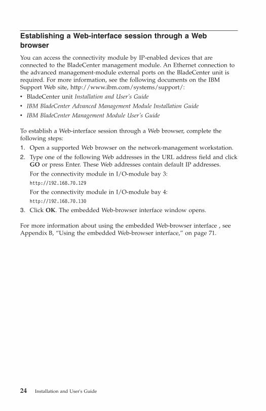
Establishing a Web-interface session through a Web
browser
You can access the connectivity module by IP-enabled devices that are
connected to the BladeCenter management module. An Ethernet connection to
the advanced management-module external ports on the BladeCenter unit is
required. For more information, see the following documents on the IBM
Support Web site, http://www.ibm.com/systems/support/:
v BladeCenter unit Installation and User’s Guide
v IBM BladeCenter Advanced Management Module Installation Guide
v IBM BladeCenter Management Module User’s Guide
To establish a Web-interface session through a Web browser, complete the
following steps:
1. Open a supported Web browser on the network-management workstation.
2. Type one of the following Web addresses in the URL address field and click
GO or press Enter. These Web addresses contain default IP addresses.
For the connectivity module in I/O-module bay 3:
http://192.168.70.129
For the connectivity module in I/O-module bay 4:
http://192.168.70.130
3. Click OK. The embedded Web-browser interface window opens.
For more information about using the embedded Web-browser interface , see
Appendix B, “Using the embedded Web-browser interface,” on page 71.
24 Installation and User's Guide
Chapter 6. Managing the connectivity module using the
advanced Management Module interface
You can use the advanced Management Module interface to access and
configure the connectivity modules. This allows you to establish a
Web-interface session with the connectivity module to retrieve information
using the advanced management module.
For more information about using the advanced Management Module
Web-interface, see the Installation and User's Guide that comes with the
application.
Note: To access a connectivity module from a network management
workstation, make sure that it is connected to an external advanced
management-module Ethernet port. If you are using a gateway to
communicate with the BladeCenter unit, set the gateway IP address for
the connectivity module to be the same as the IP address of the
advanced management module.
Important: The connectivity module is exclusively supported by the advanced
management module. Before you configure the connectivity module, make sure
that the advanced management modules in your BladeCenter unit are correctly
configured. For more information about the advanced management module,
see the User's Guide that came with your advanced management module and
at http://www.ibm.com/systems/support/.
In addition to reviewing the documentation that is described in “Related
documentation” on page 3, make sure that you review the IBM Planning and
Installation Guide for your BladeCenter unit at http://www.ibm.com/systems/support/ for information to help you prepare for system installation and
configuration.
Note: The sample screens and windows that appear in this document might
differ slightly from the screens and windows that are displayed by your
system. Screen and window content varies based on the type of
BladeCenter unit that you are using and the options that are installed.
© Copyright IBM Corp. 2007 25

Enabling external ports
To configure the connectivity module through the embedded Web-browser
interface, the IP address and subnet masks must be compatible, and the
following configuration settings in the management module must be enabled:
v External ports
v External management over all ports
v Date and time
Note: To access a connectivity module from a network management
workstation, make sure that it is connected to an external advanced
management module-Ethernet port. If you are using a gateway to
communicate with the BladeCenter unit, set the gateway IP address for
the connectivity module to the IP address of the advanced management
module.
To enable the external port, complete the following steps:
1. In the advanced Management Module Web interface, click I/O Module
Tasks > Admin/Power/Reset. The I/O Module Power/Restart window
opens.
2. In the I/O Module Advanced Setup section, select an external port to
change its port access setting to Enabled, and click Save.
Enabling external management over all ports
To enable the external management over all ports setting, complete the
following steps:
1. In the advanced Management Module Web-interface, click I/O Module
Tasks > Configuration. The I/O Module Configuration window opens.
2. Click the blade-server bay number whose setting you want to enable. The
Current IP Configuration window for the selected blade-server bay opens.
3. Click Advanced Configuration. The Advanced Configuration I/O Module
x window opens. Where x is the blade-server bay number.
4. In the Advanced Setup section, select the port to change its external
management over all ports setting to Enabled, and click Save.
Configuring the date and time
Change the date and time of the connectivity module using the CLI time
command. At the prompt, type time and press Enter.
For example, the format for June 28, 2004 8:46 P.M. (Monday) is:
>time set 6 28 2004 20 46 0 1
26 Installation and User's Guide

For detailed information about using the time and additional CLI commands,
see Appendix A, “Using the CLI,” on page 45.
Establishing a Web-interface session
To establish a Web-interface session using the advanced management module,
complete the following steps:
1. In your browser, in the URL address field, type http://xxx.xxx.xxx.xxx,
where xxx.xxx.xxx.xxx is the IP address of the advanced management
module. Click GO or press Enter. The Enter Network Password window
opens.
Note: The default IP address for the advanced management module is
192.168.70.125.
2. In the User Name field, type the initial default user name, USERID. The user
name and password are case sensitive.
3. In the Password field, type the initial default password, PASSW0RD (the sixth
character is a zero) and click OK. The Welcome window opens.
4. In the Inactive session timeout value field, select the timeout value for this
Web session, and click Continue. The Advanced Management Module
window opens.
Activating a zone configuration
To view and activate a zone configuration, complete the following steps:
1. Click I/O Module Tasks > Configuration. The I/O Module Configuration
window opens.
2. Click the link for either the connectivity module in I/O-module bay 3 or
the connectivity module in I/O-module bay 4. The I/O module
management window opens.
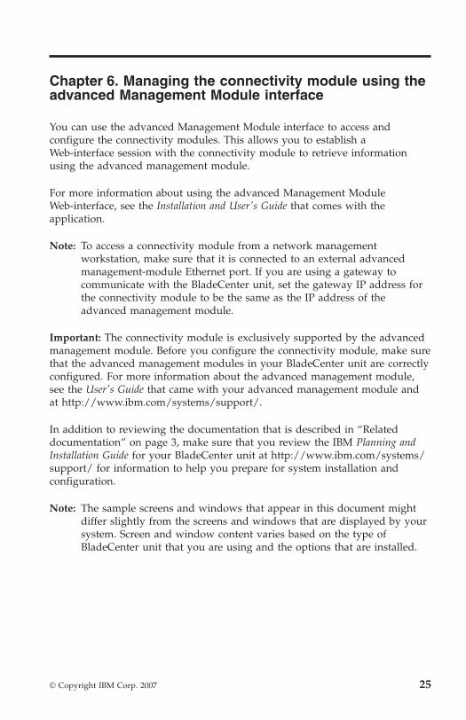
3. Click Zone Configuration Management. The Zone Configuration
Management window opens. This window displays the available zone
configurations and the current active zones.
Chapter 6. Managing the connectivity module using the advanced Management Module interface
27
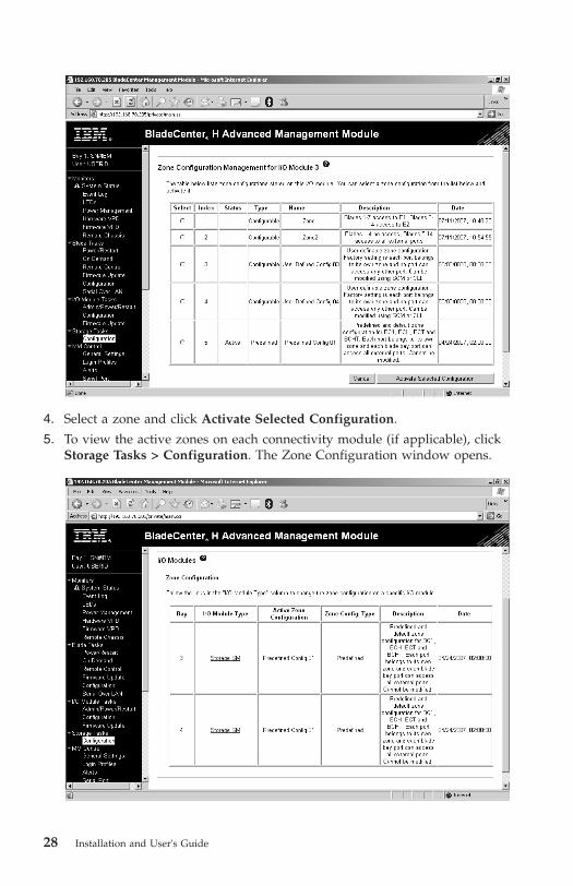
4. Select a zone and click Activate Selected Configuration.
5. To view the active zones on each connectivity module (if applicable), click
Storage Tasks > Configuration. The Zone Configuration window opens.
28 Installation and User's Guide
For more information about zoning, see Chapter 8, “Configuring zones,” on
page 33.
Chapter 6. Managing the connectivity module using the advanced Management Module interface
29

30 Installation and User's Guide

Chapter 7. Managing the connectivity module using the
Storage Configuration Manager application
The IBM Storage Configuration Manager application is a system management
application that allows you to manage and configure the connectivity modules
for use in BladeCenter units. The Storage Configuration Manager application is
standards based and uses Web-based standards.
The Storage Configuration Manager application can be installed to be run as a
standalone application or as an application launched from IBM Director 5.20.2
to manage Director storage objects. The Storage Configuration Manager
application runs as a Web server that communicates with connectivity
modules. You can connect to the Storage Configuration Manager application
from any host on the network using a standard Web browser (such as, Internet
Explorer or Firefox).
Note: For you to access a connectivity module from a network management
workstation, make sure that it is connected to an external advanced
management module-Ethernet port. If you are using a gateway to
communicate with the BladeCenter unit, set the gateway IP address for
the connectivity module to the IP address of the advanced management
module.
For more information about using the Storage Configuration Manager
application to manage and configure your connectivity module, see the Storage
Configuration Manager Planning, Installation, and Configuration Guide in the
Documentation directory on the Support CD. You can download the Storage
Configuration Manager application from http://www.ibm.com/systems/management/director/.
© Copyright IBM Corp. 2007 31

32 Installation and User's Guide
Chapter 8. Configuring zones
Zoning (integrated storage) allows you to decide how to map the hard disk
drives in storage module 1 and storage module 2 to the BladeCenter blade
servers, and how to map the blade servers to the external ports on the
connectivity module. When you configure the zoning for the BladeCenter unit,
you must determine which hard disk drives are accessible by each of the blade
servers. In addition, you must determine which external ports on the
connectivity module are accessible by each of the blade servers.
There are two types of zones that you can use for storage configuration:
v User-defined - These zones (zone 1 - zone 4) are empty so that you can
create your own zone configurations. By default, each external port belongs
to its own zone and no external port can access any other external port.
These zone configurations can be modified using the Storage Configuration
Manager application or CLI. These zones support the connectivity modules
in all BladeCenter units.
v Predefined - These zones are predefined zone configurations. Predefined
zones support the connectivity modules in the following BladeCenter units:
– Zone 5 can be used with BladeCenter Type 8677, BladeCenter Type 8852,
BladeCenter Types 8720 and 8730, and BladeCenter Type 8750.
– Zone 6 - Zone 13 can be used with BladeCenter Type 8886.
For more information about using one of the supported configuration
applications to configure zones, see one of the following sections:
v Chapter 4, “Managing the connectivity module using the Telnet interface,”
on page 15
v Chapter 5, “Managing the connectivity module using the embedded
Web-browser interface,” on page 21
v Chapter 6, “Managing the connectivity module using the advanced
Management Module interface,” on page 25
v Chapter 7, “Managing the connectivity module using the Storage
Configuration Manager application,” on page 31
User-defined zones
You can specify up to four separate user-defined zones (zone 1 through zone 4)
for the integrated-shared storage installed in the BladeCenter unit. There are
two ways to specify your own zoning configuration:
v Using either the Web-based user interface or the command-line interface
v Using the Storage Configuration Manager application
© Copyright IBM Corp. 2007 33
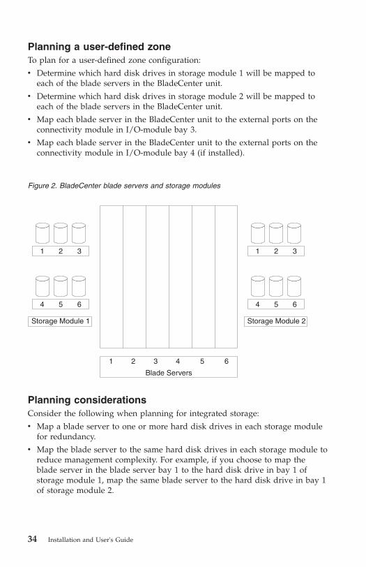
Planning a user-defined zone
To plan for a user-defined zone configuration:
v Determine which hard disk drives in storage module 1 will be mapped to
each of the blade servers in the BladeCenter unit.
v Determine which hard disk drives in storage module 2 will be mapped to
each of the blade servers in the BladeCenter unit.
v Map each blade server in the BladeCenter unit to the external ports on the
connectivity module in I/O-module bay 3.
v Map each blade server in the BladeCenter unit to the external ports on the
connectivity module in I/O-module bay 4 (if installed).
1 2 3 1 2 3
4 5 6
1 2 3 4 5 6
4 5 6
Storage Module 1 Storage Module 2
Blade Servers
Planning considerations
Consider the following when planning for integrated storage:
v Map a blade server to one or more hard disk drives in each storage module
for redundancy.
v Map the blade server to the same hard disk drives in each storage module to
reduce management complexity. For example, if you choose to map the
blade server in the blade server bay 1 to the hard disk drive in bay 1 of
storage module 1, map the same blade server to the hard disk drive in bay 1
of storage module 2.
Figure 2. BladeCenter blade servers and storage modules
34 Installation and User's Guide

Note: In addition to mapping the hard disk drives, you will have to use the
LSI Configuration Utility provided in the blade server to set up
redundancy, such as mirroring. For more information about the LSI
Configuration Utility, see the Installation and User's Guide that came with
your SAS expansion card.
Predefined zones
Zones 5 through 13 are predefined zones that cannot be modified. If you
implement a predefined configuration and then change the BladeCenter unit
(such as adding an additional blade server), you will have to choose a new
predefined configuration that matches the BladeCenter unit setup. Each zone
defines a specific zone configuration using various I/O-device configurations.
To access or modify a predefined configuration, specify the configuration using
the advanced management module configuration wizard or the Storage
Configuration Manager application.
Notes:
1. Make sure that you have one connectivity module installed in I/O-module
bay 3 in the BladeCenter unit to use single connectivity-module zones
(zone 7, zone 9, zone 11, and zone 13). For dual connectivity-module zones
(zone 6, zone 8, zone 10, zone 12), install a second module in I/O-module
bay 4).
2. When the connectivity module is initially installed into any BladeCenter
unit other than the BladeCenter Type 8886, the connectivity module
defaults to predefined zone 5 (Predefined Config 01). The last zone
activated before removing a connectivity module is the zone that is active
when a connectivity module is installed and turned on.
3. When the connectivity module is installed into a BladeCenter Type 8886
unit, you must select and activate a zone after the connectivity module is
turned on.
4. If you select a predefined zone, the advanced management module
automatically restores that zone whenever the connectivity module is
turned on or replaced.
For more information about using the advanced Management Module
Web-interface, see Chapter 6, “Managing the connectivity module using the
advanced Management Module interface,” on page 25.
For more information about using the Storage Configuration Manager
application, see Chapter 7, “Managing the connectivity module using the
Storage Configuration Manager application,” on page 31.
Chapter 8. Configuring zones 35
Zone 5 (Predefined Config 01)
Zone 5 supports BladeCenter Type 8677, BladeCenter Type 8852, BladeCenter
Types 8720 and 8730, and BladeCenter Type 8750 units. This zone allows all
the blade servers to have access to all four external ports of the connectivity
module.
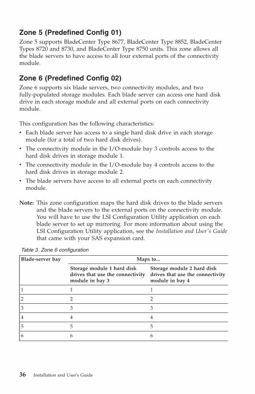
Zone 6 (Predefined Config 02)
Zone 6 supports six blade servers, two connectivity modules, and two
fully-populated storage modules. Each blade server can access one hard disk
drive in each storage module and all external ports on each connectivity
module.
This configuration has the following characteristics:
v Each blade server has access to a single hard disk drive in each storage
module (for a total of two hard disk drives).
v The connectivity module in the I/O-module bay 3 controls access to the
hard disk drives in storage module 1.
v The connectivity module in the I/O-module bay 4 controls access to the
hard disk drives in storage module 2.
v The blade servers have access to all external ports on each connectivity
module.
Note: This zone configuration maps the hard disk drives to the blade servers
and the blade servers to the external ports on the connectivity module.
You will have to use the LSI Configuration Utility application on each
blade server to set up mirroring. For more information about using the
LSI Configuration Utility application, see the Installation and User's Guide
that came with your SAS expansion card.
Table 3. Zone 6 configuration
Blade-server bay Maps to...
Storage module 1 hard disk
drives that use the connectivity
module in bay 3
Storage module 2 hard disk
drives that use the connectivity
module in bay 4
1 1 1
2 2 2
3 3 3
4 4 4
5 5 5
6 6 6
36 Installation and User's Guide
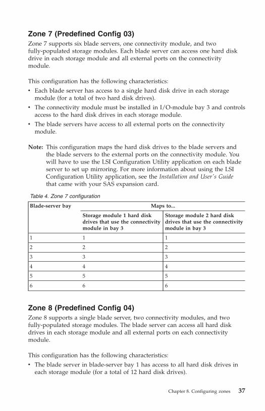
Zone 7 (Predefined Config 03)
Zone 7 supports six blade servers, one connectivity module, and two
fully-populated storage modules. Each blade server can access one hard disk
drive in each storage module and all external ports on the connectivity
module.
This configuration has the following characteristics:
v Each blade server has access to a single hard disk drive in each storage
module (for a total of two hard disk drives).
v The connectivity module must be installed in I/O-module bay 3 and controls
access to the hard disk drives in each storage module.
v The blade servers have access to all external ports on the connectivity
module.
Note: This configuration maps the hard disk drives to the blade servers and
the blade servers to the external ports on the connectivity module. You
will have to use the LSI Configuration Utility application on each blade
server to set up mirroring. For more information about using the LSI
Configuration Utility application, see the Installation and User's Guide
that came with your SAS expansion card.
Table 4. Zone 7 configuration
Blade-server bay Maps to...
Storage module 1 hard disk
drives that use the connectivity
module in bay 3
Storage module 2 hard disk
drives that use the connectivity
module in bay 3
1 1 1
2 2 2
3 3 3
4 4 4
5 5 5
6 6 6
Zone 8 (Predefined Config 04)
Zone 8 supports a single blade server, two connectivity modules, and two
fully-populated storage modules. The blade server can access all hard disk
drives in each storage module and all external ports on each connectivity
module.
This configuration has the following characteristics:
v The blade server in blade-server bay 1 has access to all hard disk drives in
each storage module (for a total of 12 hard disk drives).
Chapter 8. Configuring zones 37

v The connectivity module in I/O-module bay 3 controls access to the hard
disk drives in storage module 1.
v The connectivity module in I/O-module bay 4 controls access to the hard
disk drives in storage module 2.
v The blade server has access to all external ports on each connectivity
module.
Note: This configuration maps the hard disk drives to the blade server and the
blade server to the external ports on the connectivity modules. You will
have to use the LSI Configuration Utility application on the blade server
to set up mirroring. For more information about using the LSI
Configuration Utility application, see the Installation and User's Guide
that came with your SAS expansion card.
Table 5. Zone 8 configuration
Blade-server bay Maps to...
Storage module 1 hard disk
drives that use the connectivity
module in bay 3
Storage module 2 hard disk
drives that use the connectivity
module in bay 4
1 1, 2, 3, 4, 5, 6 1,2, 3, 4, 5, 6
Zone 9 (Predefined Config 05)
Zone 9 supports a single blade server, one connectivity module, and two
fully-populated storage modules. The blade server can access all hard disk
drives in each storage module and all external ports on the connectivity
module.
This configuration has the following characteristics:
v The blade server in blade-server bay 1 has access to all hard disk drives in
each storage module (for a total of 12 hard disk drives).
v The connectivity module must be installed in I/O-module bay 3 and controls
access to the hard disk drives in each storage module.
v The blade server has access to all external ports on the connectivity module.
Note: This configuration maps the hard disk drives to the blade server and the
blade server to the external ports on the connectivity module. You will
have to use the LSI Configuration Utility application on the blade server
to set up mirroring. For more information about using the LSI
Configuration Utility application, see the Installation and User's Guide
that came with your SAS expansion card.
38 Installation and User's Guide

Table 6. Zone 9 configuration
Blade-server bay Maps to...
Storage module 1 hard disk
drives that use the connectivity
module in bay 3
Storage module 2 hard disk
drives that use the connectivity
module in bay 3
1 1, 2, 3, 4, 5, 6 1,2, 3, 4, 5, 6
Zone 10 (Predefined Config 06)
Zone 10 supports three blade servers, two connectivity modules, and two
fully-populated storage modules. Each blade server can access two hard disk
drives in each storage module and all external ports on each connectivity
module.
Important: If you are going to use this configuration, the proper placement of
the blade servers in the BladeCenter unit is important. Blade servers must be
installed in blade-server bays 1, 3, and 5. Blade servers installed in any other
bay will not be able to access this zone.
Note: If you use a blade server that requires a 2 blade-server bay position,
make sure that the SAS expansion card is installed on the base blade
server.
This configuration has the following characteristics:
v Each blade server has access to two hard disk drives in each storage module
(for a total of four hard disk drives).
v The connectivity module in I/O-module bay 3 controls access to the hard
disk drives in storage module 1.
v The connectivity module in I/O-module bay 4 controls access to the hard
disk drives in storage module 2.
v The blade servers have access to all external ports on each connectivity
module.
Note: This configuration maps the hard disk drives to the blade server and the
blade server to the external ports on the connectivity module. You will
have to use the LSI Configuration Utility application on the blade server
to set up mirroring. For more information about using the LSI
Configuration Utility application, see the Installation and User's Guide
that came with your SAS expansion card.
Chapter 8. Configuring zones 39

Table 7. Zone 10 configuration
Blade-server bay Maps to...
Storage module 1 hard disk
drives that use the connectivity
module in bay 3
Storage module 2 hard disk
drives that use the connectivity
module in bay 4
1 1, 4 1, 4
3 2, 5 2, 5
5 3, 6 3, 6
Zone 11 (Predefined Config 07)
Zone 11 supports three blade servers, one connectivity module, and two
fully-populated storage modules. Each blade server can access two hard disk
drives in each storage module and all external ports on the connectivity
module.
Important: If you are going to use this configuration, the proper placement of
the blade servers in the BladeCenter unit is important. Blade servers must be
installed in blade server bays 1, 3, and 5. Blade servers installed in any other
bay will not be able to access this zone.
Note: If you use a blade server that requires a 2 blade-server bay position,
make sure that the SAS expansion card is installed on the base blade
server.
This configuration has the following characteristics:
v Each blade server has access to two hard disk drives in each storage module
(for a total of four hard disk drives).
v The connectivity module must be installed in blade server bay 3 and
controls access to the hard disk drives in each storage module.
v All blade servers have access to all external ports on the connectivity
module.
Note: This configuration maps the hard disk drives to the blade server and the
blade server to the external ports on the connectivity module. You will
have to use the LSI Configuration Utility application on the blade server
to set up mirroring. For more information about using the LSI
Configuration Utility application, see the Installation and User's Guide
that came with your SAS expansion card.
40 Installation and User's Guide

Table 8. Zone 11 configuration
Blade-server bay Maps to...
Storage module 1 hard disk
drives that use the connectivity
module in bay 3
Storage module 2 hard disk
drives that use the connectivity
module in bay 3
1 1, 4 1, 4
3 2, 5 2, 5
5 3, 6 3, 6
Zone 12 (Predefined Config 08)
Zone 12 supports two blade servers, two connectivity modules, and two
fully-populated storage modules. Each blade server can access three hard disk
drives in each storage module and all external ports on each connectivity
module.
Important: If you are going to use this configuration, the proper placement of
the blade servers in the BladeCenter unit is important. Blade servers must be
installed in blade-server slots 1 and 4. Blade servers installed in any other bay
will not be able to access this zone.
Note: If you use a blade server that requires a 3 blade-server bay position,
make sure that the SAS expansion card is installed on the base blade
server.
This configuration has the following characteristics:
v Each blade server has access to three hard disk drives in each storage
module (for a total of six hard disk drives).
v The connectivity module in I/O-module bay 3 controls access to the hard
disk drives in storage module 1.
v The connectivity module in I/O-module bay 4 controls access to the hard
disk drives in storage module 2.
v The blade servers have access to all external ports on each connectivity
module.
Note: This configuration maps the hard disk drives to the blade server and the
blade server to the external ports on the connectivity module. You will
have to use the LSI Configuration Utility application on the blade server
to set up mirroring. For more information about using the LSI
Configuration Utility application, see the Installation and User's Guide
that came with your SAS expansion card.
Chapter 8. Configuring zones 41

Table 9. Zone 12 configuration
Blade-server bay Maps to...
Storage module 1 hard disk
drives that use the connectivity
module in bay 3
Storage module 2 hard disk
drives that use the connectivity
module in bay 4
1 1, 3, 5 1, 3, 5
4 2, 4, 6 2, 4, 6
Zone 13 (Predefined Config 09)
Zone 13 supports two blade servers, one connectivity module, and two
fully-populated storage modules. Each blade server can access three hard disk
drives in each storage module and all external ports on the connectivity
module.
Important: If you are going to use this configuration, the proper placement of
the blade servers in the BladeCenter unit is important. Blade servers must be
installed in blade-server bays 1 and 4. Blade servers installed in any other bay
will not be able to access this zone.
Note: If you use a blade server that requires a 3 blade-server bay position,
make sure that the SAS expansion card is installed on the base blade
server.
This configuration has the following characteristics:
v Each blade server has access to three hard disk drives in each storage
module (for a total of six hard disk drives).
v The connectivity module must be installed in blade-server bay 3 controls
access to the hard disk drives in each storage module.
v The blade servers have access to all external ports on the connectivity
module.
Note: This configuration maps the hard disk drives to the blade server and the
blade server to the external ports on the connectivity module. You will
have to use the LSI Configuration Utility application on the blade server
to set up mirroring. For more information about using the LSI
Configuration Utility application, see the Installation and User's Guide
that came with your SAS expansion card.
42 Installation and User's Guide

Table 10. Zone 13 configuration
Blade-server bay Maps to...
Storage module 1 hard disk
drives that use the connectivity
module in bay 3
Storage module 2 hard disk
drives that use the connectivity
module in bay 3
1 1, 3, 5 1, 3, 5
4 2, 4, 6 2, 4, 6
Zoning configuration worksheet
Use this worksheet to plan your zoning configuration by assigning the hard
disk drives (HDD) in storage module 1 and storage module 2 to blade servers
and blade servers to external ports on the connectivity modules.
Table 11. Zone configuration worksheet
Resource Blade-server bays
1 2 3 4 5 6
Storage module 1
HDD 1
HDD 2
HDD 3
HDD 4
HDD 5
HDD 6
Storage module 2
HDD 1
HDD 2
HDD 3
HDD 4
HDD 5
HDD 6
SAS connectivity module - BladeCenter I/O-module bay 3
External
port 1
External
port 2
External
port 3
Chapter 8. Configuring zones 43
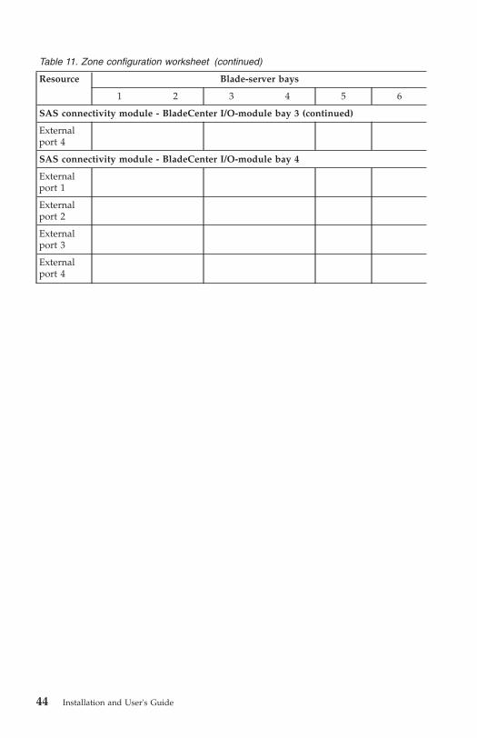
Table 11. Zone configuration worksheet (continued)
Resource Blade-server bays
1 2 3 4 5 6
SAS connectivity module - BladeCenter I/O-module bay 3 (continued)
External
port 4
SAS connectivity module - BladeCenter I/O-module bay 4
External
port 1
External
port 2
External
port 3
External
port 4
44 Installation and User's Guide

Appendix A. Using the CLI
The command-line interface (CLI) provides a convenient method for entering
commands that manage and monitor the connectivity module.
Command-line interface guidelines
All commands have the following syntax:
command argument -option parameter
The CLI-command syntax is as follows:
v keyword
v keyword <argument>
v keyword <argument>[options]
Items in the argument brackets (< >) can be changed by typing a new
argument. Items in the optional square brackets ([ ]) can be changed by typing
a new option name. You can use the Backspace and Delete keys to erase
characters behind and in front of the cursor.
For example:
sasport status all
The information for each option is returned in the order in which it was
entered and is displayed on separate lines.
Observe the following general guidelines when using the command-line
interface:
v Case sensitivity
All commands, command options, and predefined command option
parameters are case sensitive.
Note: If you receive an Illegal command. Type ? or for a list message,
make sure that you are typing the commands in the correct case; they
are case sensitive. For a list of valid commands, type help or ?.
v Delimiters
– Required parameters (arguments) are designated in the < > brackets.
– Optional parameters are designated in the [ ] brackets.
– Optional parameters designated with a separating bracket [abc|def] allow
you to change either abc or def.
© Copyright IBM Corp. 2007 45

– In a command that requires parameters, a single space is expected
between the option and the parameter. Any additional spaces are ignored.
v Output format
– Failed commands generate failure messages.
– Successful commands are indicated by the message OK.
v Strings
– Strings containing spaces should contain an underscore character (_). For
example:
snmpsyslocation IBM_lab
– String parameters can be mixed case.
v The help command lists all commands and a brief description of each
command. You can also issue the help command by typing ? .
v You can use the up arrow (�) and down arrow (�) keys in the command line
interface to access the last five commands that were entered.
CLI management commands
This section describes the CLI management commands available for the
connectivity module.
allregisters
Displays all registers on PHY phynum (in hex).
Command arguments: - <phynum> - The number of a specific register. When
this command is issued with phynum specified, the phynum defines what
register is reported. If the phynum parameter is not specified, then all registers
are reported.
Example:
>allregisters 1
clearlog
Clears the current connectivity module event log.
Command arguments: None
Example:
>clearlog
clrerrorlog
Clears the PHY Error Log on phynum (in hex).
46 Installation and User's Guide

Command arguments: <phynum> - The number of a specific PHY. When this
command is issued with phynum specified, the phynum defines the PHY whose
errors are to be cleared from the error log file. If the phynum parameter is not
defined then all PHY errors are cleared.
Example:
>clrerrorlog 01
SMP_PARERR : 00000000
Cleared PHY Error Log: 01
comport
Displays or allows you to configure the Storage Configuration Manager
base-port number (decimal).
Command arguments: <portnumber>
Where:
v portnumber - The port number that the Storage Configuration Manager is
changing to. If no port is defined, the current configuration is returned.
v SCM Request Port - Displays the port number.
v SCM Event Port - Displays the port number + 1.
v FW Update Port - Updates the port number + 2.
Example:
>comport
SCM Request Port :6641
SCM Event Port :6642
SCM FW Update Port :6643
MM Request Port :6654
MM Event Port :6655
Note: Do not use 6652 through 6655 as the port number because it will
interfere with the management module ports.
daemon
Enables or disables a specific TCP/IP daemon.
Command arguments: <type> [on|off]
Where:
v type - Defines the available daemon; such as telnet, snmp, http, sntp, or
fwupdate.
v on - Enables the daemon.
v off - Disables the daemon.
Appendix A. Using the CLI 47

v If no action is defined the current daemon status (on/off) is displayed.
Note: Changing the daemon status will restart the TCP/IP stack.
Example:
>daemon telnet off
ecmregisters
Displays ECM registers.
Command arguments: <phynum> - The ECM register phynum.
Note: When this command is issued the ECM Registers defined by phynum are
displayed. If phynum is not defined, all ECM registers are displayed.
Example:
>ecmregisters 01
exit
Ends the current telnet session.
Command arguments: None
Example:
>exit
fwcheck
Checks the status of the background Flash erase process.
Command arguments: None
Example:
>fwcheck
fwdownload
Downloads the current connectivity-module firmware from a TFTP server.
Command arguments: <ipaddress> <filename> [silent] <status>
Where:
v ipaddress - Defines the IP address of the TFTP server.
v filename - Defines the file name to download or file path from which to
download.
48 Installation and User's Guide
v silent - Disables the display of the download status.
v status - Displays the download status.
Example:
>fwdownload 192.168.70.238 fw303.fuf silent
fwerase
Starts the background flash erase process.
Command arguments: None
Example:
>fwerase
fwerasebackup
Deletes the backup firmware in the Flash ROM.
Command arguments: None
Example:
>fwerasebackup
fwrollback
Installs the prior firmware image. For externally controlled schemes, the
rollback can be toggled between two images. For boot-loader schemes, the
rollback invalidates the current firmware images and can not be undone.
Command arguments: None
Example:
>fwrollback
fwstoragedownload
Allows you to download storage-module firmware from a TFTP Server.
Command arguments: <ipaddress> <filename> <sm> [silent]
Where:
v ipaddress - Defines the IP address of the TFTP server.
v filename - Defines the file name to download or file path from which to
download.
Appendix A. Using the CLI 49
v sm - Defines the target storage module (storage module 1 or storage module
2).
v silent - Suppresses displaying the download progress.
Example:
>fwstoragedownload 192.168.70.1 updatefw.fwfile 1
get_sensor
Displays the current temperature of the connectivity module and displays the
current voltage levels for the 1.2 v, 1.8v, 3.3v, 5v, 12v, and 3.3v AUX power
supplies on the connectivity module.
Command arguments: None
Example:
>get_sensor
Status Table
ITEM VALUE STATUS PRE STATUS
-----------------------
TEMP 002 34degC 00 OK
VOL 1.2V 049F 10183V 00 OK
getsupport
Reports the internal status of the connectivity module for the IBM service
representative.
Command arguments: None
Example:
>getsupport
ipconfig
Displays the IP configuration.
Command arguments: None
Example:
>ipconfig
MAC Address..00:14:5E:C3:11:02
IP Address..192.168.70.210
Subnet Mask..255.255.255.0
Gateway..0.0.0.0
DHCP..Off
50 Installation and User's Guide

linkerrorlog
Displays link errors on PHY phynum (in hex). If phynum is not defined then
errors on all PHYs are displayed.
Command arguments: <phynum> - Defines the PHY phynum to be displayed.
Example:
>linkerrorlog 1
--------------------
Phy Number: 01
PHY_CTR_CFG..000000FE
PHY_CTR_MATCH..7CAA9595
PHY_COUNTER0..00000000
PHY_COUNTER1..00000000
ntp
Allows you to display or modify the Simple Network Time Protocol (SNTP)
Client settings.
Command arguments: <get|set> [<polling> [<frequency> <timeZone> <PriServer>
[SecServer]]]
Where:
v get - Displays the current SNTP settings. Defines the IP address of the TFTP
server.
v set - Modifies the SNTP settings polling.
v polling - Allows you to change the polling setting to on to restart SNTP
polling or to off to stop SNTP.
v frequency - Displays the SNTP polling frequency in seconds
v timeZone - Displays the time difference from GMT (Hours:Minutes).
v PriServer - Displays the IP address of the primary SNTP server.
v SecServer - Displays the IP address of the secondary SNTP server.
Examples:
>ntp get
>ntp set off
>ntp set on 86400 -4 192.168.1.1 192.168.1.11
>ntp set on 3600 9:30 192.168.1.11
Appendix A. Using the CLI 51

pcmerrorlog
Displays the PCM error log for PHY phynum. If no phynum is specified, then
errors on all ports are displayed.
Command arguments: <phynum> - Defines the specific phynum on which
errors were generated.
Example:
>pcmerrorlog 1
--------------------
Phy Number: 01
PCM Counter Configuration:00000000
PCM Counter:00000000
PCM _BAD_OPEN_CNT:00000000
phy
Allows you to toggle PHY debug on and off.
Command arguments: [on|off] - Allows you to turn on or turn off the debug of
a specific PHY.
Example:
>phy on
PHY debug is on
phyattribute
Allows you to display, configure, or clear the phy attributes of PHY
Command arguments: [set|clear|get] <phy> [routing method] [txinvert] [rxinvert]
Where:
v set - Allows you to configure the PHY attributes.
v clear - Erases all phy attributes.
v get - Displays the attributes of all PHYs.
v phy - Defines all the PHYs or a particular PHY. The phy options are all/ 0/
1,...
v routing method - Defines the routing method as a direct, subtractive, or table
method.
v txinvert - Allows you to invert (inverted) or normalize (not inverted) the
transmit signal.
v rxinvert - Allows you to invert (inverted) or normalize (not inverted) the
receive signal.
52 Installation and User's Guide

Examples:
>phyattribute clr all
>phyattribute get all
>phyattribute clr 0
>phyattribute get 0
>phyattribute set 0 1
>phyattribute set 0 1 0 1 - sets phy 0 attributes:Subtractive routing, Rx not inverted, Tx inve
phyerrorlog
Displays the error log on PHY phynum (in hex). If no phynum is defined then
all PHY errors are displayed.
Command arguments: <phynum> - Defines the specific PHY phynum error log.
Example:
>phyerrorlog 1
phyregisters
Displays the PHY register on PHY phynum (in hex).
Command arguments: <phynum> - Defines the specific PHY register.
Example:
>phyregisters 20
post_results
Displays the result of the initial power-on-self-test (POST). Three POST choices
are available from the advanced memory module; standard, extended, and
extended with full memory.
Command arguments: None
Example:
>post_results
POST results:
PD1 Devices passed
EEPROM passed
WatchDog function passed
...
printphystat
Displays the statistics for PHY phynum. If no phynum is defined, then the
status of all PHY are displayed.
Command arguments: <phynum> - Defines the specific PHY phynum (in hex).
Appendix A. Using the CLI 53

Example:
>printphystat 1
Phy Number: 01
Phy_stat.Phy_Stat:...1
Phy_stat.Disable_Cause:...0
Phy_stat.Time_Phy_State:...010DB32E
Phy_stat.Enabled_notify:....00
Phy_stat.Notify_sent:....0
Phy_stat.LastHBTime:....00000000
reset
Resets the connectivity module.
Command arguments: None
Example:
>reset
restoremfgdef
Restores the manufacturing default configuration.
Command arguments: None
Example:
>restoremfgdef
sasaddr
Displays the SAS ID for the connectivity module.
Command arguments: <get> - Allows you to display the SAS ID from
NVRAM.
Example:
>sasaddr get
SASAddress:50050764100077C0
54 Installation and User's Guide

sasport
Allows you to control and query the SAS port.
Command arguments: <cmd> [<arg>] - Allows you to change the SAS port
configuration. The cmd options are:
v “sasport clrerrcnt” on page 55
v “sasport disable” on page 56
v “sasport enable” on page 56
v “sasport geterrcnt” on page 56
v “sasport reset” on page 57
v “sasport startlb” on page 58
v “sasport startsnoop” on page 58
v “sasport status” on page 57
v “sasport stopsnoop” on page 58
v “sasport stoplb” on page 58
sasport clrerrcnt
Clears the sasport error counters of SAS port PHY(s).
Command arguments: [all|blade|Bn|En|external]
Where:
v all - Clears error counters for all SAS ports.
v blade - Clears error counters all blade server ports.
v Bn - Clears error counters for a specific blade server port.
v En - Clears error counters for a specific external port.
v external - Clears error counters for all external ports.
Example:
>sasport clrerrcnt E1
SAS ID Port Name Inv.Dword Disparity dwordsLost Reset Cnt
_____ + _______________ +_____________+___________+_____________+____________
E1 External Port 1
PHY 1C 0x00000000000 0x00000000000 0x00000000000 0x00000000000
PHY 1D 0x00000000000 0x00000000000 0x00000000000 0x00000000000
PHY 1E 0x00000000000 0x00000000000 0x00000000000 0x00000000000
PHY 1F 0x00000000000 0x00000000000 0x00000000000 0x00000000000
Appendix A. Using the CLI 55
sasport disable
Disables ports on a connectivity module.
Command arguments: [all|blade|Bn|En|external]
Where:
v all - Disable all SAS ports.
v blade - Disable all blade server ports.
v Bn - Disable a specific blade server port.
v En - Disable a specific external port.
v external - Disable all external ports.
Example:
>sasport disable E1
E1 External Port 1 OK
sasport enable
Enables the ports on a connectivity module.
Command arguments: [all|blade|Bn|En|external]
Where:
v all - Enable all SAS ports.
v blade - Enable all blade server ports.
v Bn - Enable a specific blade server port.
v En - Enable a specific external port.
v external - Enable all external ports.
Example:
>sasport enable E1
E1 External Port 1 is already enable. Request ignored.
sasport geterrcnt
Displays the PHY error counters for each PHY of the SAS port.
Command arguments: [all|blade|Bn|En|external]
Where:
v all - Display the PHY Error Counters for all SAS ports.
v blade - Display the PHY Error Counters for all external ports.
v Bn - Display the PHY Error Counters for all blade server ports.
v En - Display the PHY Error Counters for external port n.
56 Installation and User's Guide

v external - Display the PHY Error Counters for blade server port n.
Example:
>sasport geterrcnt all
sasport reset
Resets the SAS link through all PHYs belonging to the SAS port defined by the
argument.
Command arguments: [all|blade|Bn|En|external]
Where:
v all - Resets all SAS ports.
v blade - Resets all blade server ports.
v Bn - Resets a specific blade server port.
v En - Resets a specific external port.
v external - Resets all external ports.
Examples:
>sasport reset all
>sasport reset E1
>sasport reset B14
sasport status
Displays the SAS port status.
Command arguments: [all|blade|Bn|En|external]
Where:
v all - Displays SAS port status for all SAS ports.
v blade - Displays SAS port status for all blade server ports.
v Bn - Displays SAS port status for a specific blade server port.
v En - Displays SAS port status for a specific external port.
v external - Displays SAS port status for all external ports.
Example:
>sasport status E1
ID SAS Port Name SAS Address Enable Act Flt Status
__+________________+____________+_______+____+_____+______
E1 External Port 1 True Off Off NoCable
PHY 1C 000000000000 True Off Off NoCable
PHY 1D 000000000000 True Off Off NoCable
PHY 1E 000000000000 True Off Off NoCable
PHY 1F 000000000000 True Off Off NoCable
Appendix A. Using the CLI 57
sasport startlb
Starts the external loop back test on an external SAS port.
Command arguments: <test port> - Defines the loop back test port.
Example:
>sasport startlb E1
SAS PHY Internal Loopback (Port=E1 PHY=1)........FAIL-=not in sync
SAS PHY Internal Loopback (Port=E1 PHY=2)........FAIL-=not in sync
SAS PHY Internal Loopback (Port=E1 PHY=3)........FAIL-=not in sync
SAS PHY Internal Loopback (Port=E1 PHY=4)........FAIL-=not in sync
sasport startsnoop
Starts SAS port-snooping which mirrors the SAS traffic transmit and receive
data from the internal SAS port (traffic port) to the external SAS port (listen
port).
Command arguments: <traffic port> <listen port> <phy>
Where:
v traffic port - Defines the internal SAS port.
v external - Defines the external SAS port.
v phy - Defines the SAS PHY.
Example:
>sasport startsnoop B1 E1 1
Starting SAS Port snooping was successful.
Traffic Port: B1
Listening Port: E1
Mirrors Rx to B1 MAIN> E1 PHY 1, TX FROM B1 MAIN> E1 PHY 2
sasport stoplb
Stops the remote loop back test on the external SAS port.
Command arguments: <test port> - Defines the loop back test port.
Example:
>sasport stopLB E1
sasport stopsnoop
Stops snooping on a port that mirrors the SAS traffic transmit and receive from
the internal SAS port and the external SAS port.
Command arguments: <traffic port> - Defines the snooping on the traffic port.
58 Installation and User's Guide
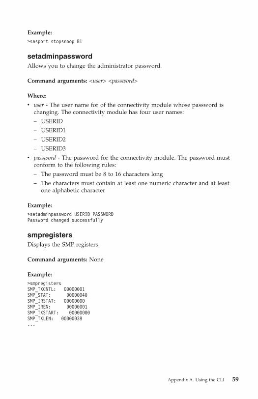
Example:
>sasport stopsnoop B1
setadminpassword
Allows you to change the administrator password.
Command arguments: <user> <password>
Where:
v user - The user name for of the connectivity module whose password is
changing. The connectivity module has four user names:
– USERID
– USERID1
– USERID2
– USERID3
v password - The password for the connectivity module. The password must
conform to the following rules:
– The password must be 8 to 16 characters long
– The characters must contain at least one numeric character and at least
one alphabetic character
Example:
>setadminpassword USERID PASSW0RD
Password changed successfully
smpregisters
Displays the SMP registers.
Command arguments: None
Example:
>smpregisters
SMP_TXCNTL: 00000001
SMP_STAT: 00000040
SMP_IRSTAT: 00000000
SMP_IREN: 00000001
SMP_TXSTART: 00000000
SMP_TXLEN: 00000038
...
Appendix A. Using the CLI 59

snmpcommunity
Allows you to display or define the SNMP community strings. The maximum
number of community characters allowed is 24. There are no spaces allowed in
the string and you must use the underscore character to enter a space.
Command arguments: <rd | rw> [public | private]
Where:
v rd - Displays the SNMP READ community.
v rw - Displays the SNMP WRITE community.
v public - Configures the SNMP community to public.
v private - Configures the SNMP community to private.
Example:
>smpcommunity rd
SNMP READ Community String = public
snmpsyscontact
Allows you to display or define the SNMP MIB-2 system contact-display
information. The maximum number of contact-information characters allowed
is 64. There are no spaces allowed in the string and you must use the
underscore character to enter a space.
Command arguments: <sysContact> - Defines the SNMP MIB-2 system contact
information.
Example:
>snmpsyscontact Contact_Me
snmpsysdescr
Allows you to display or define the SNMP MIB-2 system description-display
information. The maximum number of system-description characters allowed is
64. There are no spaces allowed in the string and you must use the underscore
character to enter a space.
Command arguments: <sysdescr> - Defines the SNMP MIB-2 system
description. If no sysdescr is defined the current information is displayed.
Example:
>snmpsysdescr IBM BladeCenter SAS Connectivity Module
IBM Bladecenter SAS Connectivity Module
60 Installation and User's Guide
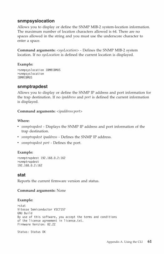
snmpsyslocation
Allows you to display or define the SNMP MIB-2 system-location information.
The maximum number of location characters allowed is 64. There are no
spaces allowed in the string and you must use the underscore character to
enter a space.
Command arguments: <sysLocation> - Defines the SNMP MIB-2 system
location. If no sysLocation is defined the current location is displayed.
Example:
>snmpsyslocation IBM@IBMUS
>snmpsyslocation
IBM@IBMUS
snmptrapdest
Allows you to display or define the SNMP IP address and port information for
the trap destination. If no ipaddress and port is defined the current information
is displayed.
Command arguments: <ipaddress:port>
Where:
v snmptrapdest - Displays the SNMP IP address and port information of the
trap destination.
v snmptrapdest ipaddress - Defines the SNMP IP address.
v snmptrapdest port - Defines the port.
Example:
>snmptrapdest 192.168.0.2:162
>snmptrapdest
192.168.0.2:162
stat
Reports the current firmware version and status.
Command arguments: None
Example:
>stat
Vitesse Semiconductor VSC7157
GNU Build
By use of this software, you accept the terms and conditions
of the license agreement in license.txt.
Firmware Version: 02.22
Status: Status OK
Appendix A. Using the CLI 61
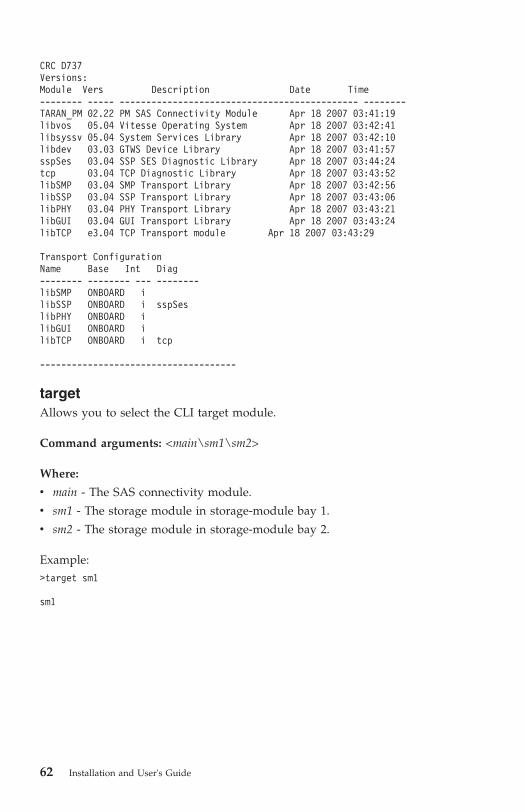
CRC D737
Versions:
Module Vers Description Date Time
-------- ----- --------------------------------------------- --------
TARAN_PM 02.22 PM SAS Connectivity Module Apr 18 2007 03:41:19
libvos 05.04 Vitesse Operating System Apr 18 2007 03:42:41
libsyssv 05.04 System Services Library Apr 18 2007 03:42:10
libdev 03.03 GTWS Device Library Apr 18 2007 03:41:57
sspSes 03.04 SSP SES Diagnostic Library Apr 18 2007 03:44:24
tcp 03.04 TCP Diagnostic Library Apr 18 2007 03:43:52
libSMP 03.04 SMP Transport Library Apr 18 2007 03:42:56
libSSP 03.04 SSP Transport Library Apr 18 2007 03:43:06
libPHY 03.04 PHY Transport Library Apr 18 2007 03:43:21
libGUI 03.04 GUI Transport Library Apr 18 2007 03:43:24
libTCP e3.04 TCP Transport module Apr 18 2007 03:43:29
Transport Configuration
Name Base Int Diag
-------- -------- --- --------
libSMP ONBOARD i
libSSP ONBOARD i sspSes
libPHY ONBOARD i
libGUI ONBOARD i
libTCP ONBOARD i tcp
-------------------------------------
target
Allows you to select the CLI target module.
Command arguments: <main\sm1\sm2>
Where:
v main - The SAS connectivity module.
v sm1 - The storage module in storage-module bay 1.
v sm2 - The storage module in storage-module bay 2.
Example:
>target sm1
sm1
62 Installation and User's Guide

time
Allows you to display or define the current date and time settings.
Command arguments: [<set|get>]<month> <day> <year> <hour> <min> <sec>
<W>
Where:
v set - Sets the time.
v get - Displays the current time.
v month - Displays the month using the MM format.
v day - Displays the day using the DD format.
v year - Displays the year using the YYYY format.
v hour - Displays the hour using the HH format.
v minute - Displays the minutes in MM format.
v seconds - Displays the seconds in SS format.
v W - Displays the day of the week.
Examples:
>time set 6 19 2007 8 37 05 2
MM/DD/YYYY HH:MM:SS (www)
06/19/2007 08:37:05 (TUE) 170/365
Seconds since 01/01/1970 = 0x467795B1
>time get
MM/DD/YYYY HH:MM:SS (www)
06/19/2007 08:38:02 (TUE) 170/365
Seconds since 01/01/1970 = 0x467795EA
version
Displays the hardware, firmware, and CPU version of the connectivity module.
Command arguments: None
Example:
>version
Vitesse Semiconductor VSC7157
Chip Version : 02
Firmware Version: 02.03
CPU Version : 0000AC13
Appendix A. Using the CLI 63

xmlconnections
Displays all of the current XML connections.
Command arguments: None
Example:
>xmlconnections
Main Port Connection 0
activePCB : BFB1294C
loggedIn : True
inactivityTime : 47331
localPort : 6641
remotePort : 3994
state : Established
Event Port Connection 0
activePCB : BFB129F0
localPort : 6642
remotePort : 3995
state : Established
xmlevents
Displays all of the XML event queues.
Command arguments: None
Example:
>xmlevents
Event Port Connection 0
activePCB : BFB129F0
eventCount : 0000
Event Port Connection 1
activePCB : 00000000
eventCount : 0000
Event Port Connection 2
activePCB : 00000000
eventCount : 0000
Event Port Connection 3
activePCB : 00000000
eventCount : 0000
Event Port Connection 4
activePCB : 00000000
eventCount : 0000
zoneconfig
Displays and allows you to change the SAS zone configuration.
64 Installation and User's Guide

Command arguments: <cmd> [<arg>] - Allows you to change the SAS zone
configuration. The cmd options are:
v “zoneconfig apply” on page 65
v “zoneconfig compare”
v “zoneconfig copy” on page 66
v “zoneconfig deny” on page 66
v “zoneconfig disable” on page 66
v “zoneconfig erase” on page 67
v “zoneconfig get” on page 67
v “zoneconfig groupassign” on page 67
v “zoneconfig permit” on page 68
v “zoneconfig setdesc” on page 68
v “zoneconfig setname” on page 68
v “zoneconfig stat” on page 69
zoneconfig apply
Applies a stored zone to hardware zone table.
Command arguments: <zone#> - Defines the zone number to be applied.
Numbers 1 through 4 are the stored zones and the numbers 5 through 13 are
the predefined zones.
Example:
>zoneconfig apply 1
Zone #01 has applied to hardware zone table.
zoneconfig compare
Compare two zone configurations.
Command arguments: <SourceZone#> <DestZone#>
Where:
v SourceZone# - Defines the source-zone number to be compared. The numbers
1 through 4 define the stored-zone locations and the numbers 5 through 13
define the predefined-zone locations.
v DestZone# - Defines the destination-zone number to be compared. The
numbers 1 through 4 define the stored-zone locations and the numbers 5
through 13 define the predefined-zone locations.
Example:
>zoneconfig compare 5 1
Appendix A. Using the CLI 65

zoneconfig copy
Copies the zone configurations.
Command arguments: <SourceZone#> <DestZone#>
Where:
v SourceZone# - Defines the source-zone number to be copied from. The
numbers 1 through 4 define the stored-zone locations, the numbers 5
through 13 define the predefined-zone locations, and hw defines the
hardware table.
v DestZone# - Defines the source-zone number to be copied into. The numbers
1 through 4 define the stored-zone locations, the numbers 5 through 13
define the predefined-zone locations, and hw defines the hardware table.
Example:
>zoneconfig copy 5 1
Zone Configuration has copied from Zone #05 to Zone #01 successfully.
zoneconfig deny
This command modifies the zone permission table of a stored zone. The
command denies the SAS connection between two specific groups.
Command arguments: <StoredZone> <Group1> <Group2>
Where:
v StoredZone# - Defines the stored zone number to be modified. (zone 1
through zone 4)
v Group1 - The first group ID for which a connection is denied.
v Group2 - The second group ID for which a connection is denied.
Example:
>zoneconfig deny StoredZone #01
Stored Zone #01 has been modified successfully.
zoneconfig deny 1 10 11
zoneconfig disable
This command disables the Zoning function on the SAS connectivity module.
This command will assign the Group ID of 0 for each PHY and will clear the
permission table. All PHYs are disabled if the disablephy option is set. In this
case, the SasPort Enable command must be used to re-enable PHYs because the
apply subcommand does not enable the PHYs.
Command arguments: [<disablephy>] - Disables all zone configuration phys.
66 Installation and User's Guide

Example:
>zoneconfig disable
Zoning disabled
zoneconfig erase
Erases the zone configuration located in a stored zone
Command arguments: <StoredZone#> - The number of the zone configuration
to erase. The numbers 1 through 4 specify the stored zone and the numbers 5
through 13 specify the predefined zone.
Example:
>zoneconfig erase 2
zoneconfig get
Displays the zone configuration located in a stored zone.
Command arguments: <zone#> - Defines the zone number to be displayed. The
numbers 1 through 4 define the stored zone, the numbers 5 through 13 define
the predefined zone, and the hw defines the HW table.
Example:
>zoneconfig get 1
zoneconfig groupassign
This command modifies the PHY zone configuration of a stored zone This
command also assigns a Group ID to all PHYs belonging to the SAS port.
Command arguments: <StoredZone#> <SasPortId> <ZoneGroupId>
Where:
v StoredZone# - Defines the zone to be modified.
v SasPortId - Defines the SAS port ID.
– all - Defines all SAS ports.
– blade - Defines all blade server ports.
– Bn - Defines a specific blade server port.
– En - Defines a specific external port.
– external - Defines all external ports.
v ZoneGroupID - Defines the zone group ID to be assigned to the SAS port.
Example:
>zoneconfig groupassign 1 b1 10
Zone Group of 10 is assigned to SAS Port B1 (Blade bay Connection 1 )
Stored Zone #01 has been modified successfully.
Appendix A. Using the CLI 67

zoneconfig permit
This command modifies the zone permission table of a stored zone. This
command also permits the SAS connection between two groups.
Command arguments: <StoredZone#> <Group1> <Group2>
Where:
v StoredZone# - Defines the stored zone number to be modified (1- 4).
v Group1 - The first group ID for which a connection is permitted.
v Group2 - The second group ID for which a connection is permitted.
Example:
>zoneconfig permit 1 10 11
Stored Zone #01 has been modified successfully.
zoneconfig setdesc
Allows you to display or define the stored-zone description. There are no
spaces allowed in the string and you must use the underscore character to
enter a space.
Command arguments: <StoredZone#> <description>
Where:
v StoredZone# - Defines the stored-zone number to be modified (zone 1
through zone 4).
v description - Defines the stored-zone description. If no description is defined,
this argument displays the current information.
Example:
>zoneconfig setdesc 1 A_zone_with_blade_1_seeing_only_external_port_1
zoneconfig setname
Allows you to display or define the zoneconfig stored-zone name. There are
no spaces allowed in the string and you must use the underscore character to
enter a space.
Command arguments: <StoredZone#> <zonename>
Where:
v StoredZone# - Defines the stored-zone number to be modified (zone 1
through zone 4).
v zonename - Defines the name of the stored zone.
68 Installation and User's Guide

Example:
>zoneconfig setname 1 My_Zone
zoneconfig stat
Displays the current zone configuration.
Command arguments: None
Example:
>zoneconfig stat
Zone Configuration Status.
Zoning Function: Enabled
Current Zone: Predefined Config 02
Default Zone: Undefined Configuration
Zone Apply for MAIN: Applied
Zone Apply for SM1: Applied
Zone Apply for SM2: Applied
Appendix A. Using the CLI 69

70 Installation and User's Guide

Appendix B. Using the embedded Web-browser
interface
This appendix provides information about using the embedded Web-browser
interface to configure your connectivity module.
Web-browser interface requirements
The embedded Web-browser interface works with Web browsers which
support Extensible Stylesheet Language Transformation (XSLT) version 1.0 and
application/xml MIME types. The supported Web browsers for the
connectivity module is Internet Explorer versions 6.0 and 7.0.
Notes:
1. To configure the connectivity module through the embedded Web-browser
interface, the IP address and subnet masks must be compatible and all
external ports must be enabled. For more information about enabling
external ports, see “Enabling external ports” on page 21.
2. To access a connectivity module from a network management workstation,
make sure that it is connected to an external management-module Ethernet
port.
Logging into the Web-browser interface
To login to the Web-browser interface, complete the following steps:
1. In your browser, in the URL address field, type http://xxx.xxx.xxx.xxx,
where xxx.xxx.xxx.xxx is the IP address of the connectivity module. Click
GO or press Enter. For example, http://sas_switch_ip_address. The
Web-browser interface Login window opens.
2. In the User ID field, enter your user ID. The user name and password are
case sensitive.
3. In the Password field, enter your password and click Login. The Welcome
window opens.
Monitoring the connectivity module
The Web-browser interface allows you to monitor the connectivity module,
external ports, and blade-server bay connections; and to configure
connectivity-module zoning. You can access each window in two ways:
v Selecting the specific link in a Web-browser interface window. For example,
clicking the View Logs link in a Web-browser interface window.
© Copyright IBM Corp. 2007 71
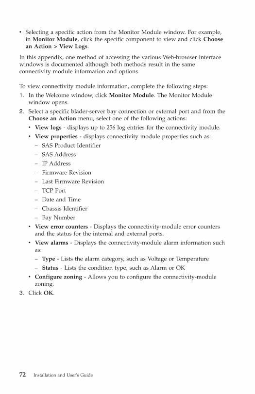
v Selecting a specific action from the Monitor Module window. For example,
in Monitor Module, click the specific component to view and click Choose
an Action > View Logs.
In this appendix, one method of accessing the various Web-browser interface
windows is documented although both methods result in the same
connectivity module information and options.
To view connectivity module information, complete the following steps:
1. In the Welcome window, click Monitor Module. The Monitor Module
window opens.
2. Select a specific blader-server bay connection or external port and from the
Choose an Action menu, select one of the following actions:
v View logs - displays up to 256 log entries for the connectivity module.
v View properties - displays connectivity module properties such as:
– SAS Product Identifier
– SAS Address
– IP Address
– Firmware Revision
– Last Firmware Revision
– TCP Port
– Date and Time
– Chassis Identifier
– Bay Number
v View error counters - Displays the connectivity-module error counters
and the status for the internal and external ports.
v View alarms - Displays the connectivity-module alarm information such
as:
– Type - Lists the alarm category, such as Voltage or Temperature
– Status - Lists the condition type, such as Alarm or OK
v Configure zoning - Allows you to configure the connectivity-module
zoning.
3. Click OK.
72 Installation and User's Guide
Updating firmware
To update the connectivity-module firmware to the latest version, complete the
following steps:
1. In the Monitor Module window, click Update Firmware. The Update
Firmware window opens.
2. In the Firmware File field, enter the new firmware file name.
Or
click Browse and locate the firmware file.
3. Click Install to install the new file. An installation confirmation window
opens.
4. Click OK or Cancel. If the installation of the new firmware file is
successful, an installation confirmation window opens. If there are errors
during the installation, an error-message window opens.
For the latest firmware update, see http://www.ibm.com/systems/support/.
Changing the password
To change the connectivity-module password, complete the following steps:
1. In the Monitor Module window, click Administer Users. The User
Administration window opens.
2. Select a User ID and click Modify Password. The Modify Password
window opens.
3. In the Old Password field, enter the current password.
4. In the New Password field, enter the new password. Passwords must be
8-16 characters long and must contain at least one number and one letter.
5. In the Confirm New Password field, enter the new password again.
6. Click OK. The new password is saved and updated.
Configuring zoning
You can use the Web-browser interface to display, activate, and modify current
active-zone configurations and current working-zone configurations for the
connectivity module.
Activating a zone working configuration
To activate a connectivity-module zone, complete the following steps:
1. In the Web-browser interface window, click Configuration > Zoning. The
Manage Fabric window opens and displays the current active configuration
and working configuration.
Appendix B. Using the embedded Web-browser interface 73

2. From the Working Configuration menu, select a working configuration and
click Activate this Configuration. The selected zone is activated.
Viewing a zone working configuration
To view a zone working configuration, in the Manage Fabric window, from the
Working Configuration menu, select a working configuration. The Zone
Groups tab opens and displays the zone group ID for each external port.
Note: Predefined zones cannot be modified.
Modifying a zone working configuration
Each external port of the connectivity module is assigned a specific zone group
ID. You can add or remove access permission for which ports are zoned
together in zone group IDs. You can also copy a predefined zone and use it as
a user-defined zone for editing purposes. To copy a predefined zone, use the
zoneconfig copy command in the CLI interface. For more information on the
zoneconfig copy command, see “zoneconfig copy” on page 66.
To modify a working zone configuration:
1. In the Web-browser interface window, click Configuration > Zoning. The
Manage Fabric window opens and displays the current active configuration
and working configuration.
74 Installation and User's Guide

2. From the Working Configuration menu, select a working zone
configuration to modify and click the Basic Zone Permission Table tab.
The Basic Zone Permission Table tab opens.
3. In the View by menu, select the zone group ID to remove or add zoned
ports.
4. To add ports to a zone group ID, in the Not Mapped To table, click to
select each external port to be added; then, click Add to Permission Table.
The selected ports are permitted access to the zone group ID.
5. To remove ports from a zone group ID, in the Mapped to table, click to
select each external port to be removed and click Remove from Permission
Table. The selected ports are denied access to the zone group ID.
Appendix B. Using the embedded Web-browser interface 75

6. After you complete the modifications, click Activate this Configuration to
save your changes.
76 Installation and User's Guide
Appendix C. Getting help and technical assistance
If you need help, service, or technical assistance or just want more information
about IBM products, you will find a wide variety of sources available from
IBM to assist you. This section contains information about where to go for
additional information about IBM and IBM products, what to do if you
experience a problem with your system, and whom to call for service, if it is
necessary.
Before you call
Before you call, make sure that you have taken these steps to try to solve the
problem yourself:
v Check all cables to make sure that they are connected.
v Check the power connectivity modules to make sure that the system and
any optional devices are turned on.
v Use the troubleshooting information in your system documentation, and use
the diagnostic tools that come with your system. Information about
diagnostic tools is in the Hardware Maintenance Manual and Troubleshooting
Guide or Problem Determination and Service Guide on the IBM Documentation
CD that comes with your system. For specific troubleshooting information
about the connectivity module, including SAS and Ethernet-connection
issues, see the latest Readme file at http://www.ibm.com/systems/support/. The readme contains the latest information and updates for the
connectivity module firmware.
Note: For some IntelliStation models, the Hardware Maintenance Manual and
Troubleshooting Guide is available only from the IBM support Web site.
v Go to the IBM support Web site at http://www.ibm.com/systems/support/
to check for technical information, hints, tips, and new device drivers or to
submit a request for information.
You can solve many problems without outside assistance by following the
troubleshooting procedures that IBM provides in the online help or in the
documentation that is provided with your IBM product. The documentation
that comes with IBM systems also describes the diagnostic tests that you can
perform. Most systems, operating systems, and programs come with
documentation that contains troubleshooting procedures and explanations of
error messages and error codes. If you suspect a software problem, see the
documentation for the operating system or program.
© Copyright IBM Corp. 2007 77

Using the documentation
Information about your IBM system and preinstalled software, if any, or
optional device is available in the documentation that comes with the product.
That documentation can include printed documents, online documents, readme
files, and help files. See the troubleshooting information in your system
documentation for instructions for using the diagnostic programs. The
troubleshooting information or the diagnostic programs might tell you that you
need additional or updated device drivers or other software. IBM maintains
pages on the World Wide Web where you can get the latest technical
information and download device drivers and updates. To access these pages,
go to http://www.ibm.com/systems/support/ and follow the instructions.
Also, some documents are available through the IBM Publications Center at
http://www.ibm.com/shop/publications/order/.
Getting help and information from the World Wide Web
On the World Wide Web, the IBM Web site has up-to-date information about
IBM systems, optional devices, services, and support. The address for IBM
System x™ and xSeries® information is http://www.ibm.com/systems/x/. The
address for IBM BladeCenter information is http://www.ibm.com/systems/bladecenter/. The address for IBM IntelliStation® information is
http://www.ibm.com/intellistation/.
You can find service information for IBM systems and optional devices at
http://www.ibm.com/systems/support/.
Software service and support
Through IBM Support Line, you can get telephone assistance, for a fee, with
usage, configuration, and software problems with System x and xSeries servers,
BladeCenter products, IntelliStation workstations, and appliances. For
information about which products are supported by Support Line in your
country or region, see http://www.ibm.com/services/sl/products/.
For more information about Support Line and other IBM services, see
http://www.ibm.com/services/, or see http://www.ibm.com/planetwide/ for
support telephone numbers. In the U.S. and Canada, call 1-800-IBM-SERV
(1-800-426-7378).
Hardware service and support
You can receive hardware service through IBM Services or through your IBM
reseller, if your reseller is authorized by IBM to provide warranty service. See
http://www.ibm.com/planetwide/ for support telephone numbers, or in the
U.S. and Canada, call 1-800-IBM-SERV (1-800-426-7378).
78 Installation and User's Guide

In the U.S. and Canada, hardware service and support is available 24 hours a
day, 7 days a week. In the U.K., these services are available Monday through
Friday, from 9 a.m. to 6 p.m.
IBM Taiwan product service
IBM Taiwan product service contact information:
IBM Taiwan Corporation
3F, No 7, Song Ren Rd.
Taipei, Taiwan
Telephone: 0800-016-888
Appendix C. Getting help and technical assistance 79

80 Installation and User's Guide

Appendix D. IBM Statement of Limited Warranty
Z125-4753-09 08/2006
Part 1 - General Terms
Part 1 - General Terms
This Statement of Limited Warranty includes Part 1 - General Terms, Part 2 -
Country-unique Terms, and Part 3 - Warranty Information. The terms of Part 2
replace or modify those of Part 1.
The warranties provided by IBM in this Statement of Limited Warranty apply
only to Machines you purchase for your use, and not for resale. The term
“Machine” means an IBM machine, its features, conversions, upgrades,
elements, or accessories, or any combination of them. The term “Machine”
does not include any software programs, whether pre-loaded with the
Machine, installed subsequently or otherwise. NOTHING IN THIS
STATEMENT OF LIMITED WARRANTY AFFECTS ANY STATUTORY
RIGHTS OF CONSUMERS THAT CANNOT BE WAIVED OR LIMITED BY
CONTRACT.
This Statement of Limited Warranty is available, in multiple languages, at the
following IBM Internet website: http://www.ibm.com/servers/support/machine_warranties/.
What this Warranty Covers
IBM warrants that each Machine is free from defects in materials and
workmanship and conforms to its Specifications. “Specifications” is information
specific to a Machine in a document entitled “Official Published Specifications”
which is available upon request.
During the warranty period, IBM provides repair and exchange service for the
Machine under the type of warranty service IBM designates for the Machine.
The warranty period for the Machine is a fixed period starting on its original
Date of Installation. The date on your purchase invoice or sales receipt is the
Date of Installation unless IBM or your reseller informs you otherwise. The
warranty period, type of warranty, and service level that apply to your
Machine are designated in Part 3.
Many features, conversions, or upgrades involve the removal of parts and their
return to IBM. An IBM part that replaces a removed part will assume the
warranty service status of the removed part. An IBM part that is added to a
Machine without replacing a previously-installed part is subject to warranty
© Copyright IBM Corp. 2007 81

effective on its Date of Installation. Unless IBM specifies otherwise, the
warranty period, type of warranty, and service level of such part is the same as
the Machine on which it is installed.
Unless IBM specifies otherwise, these warranties apply only in the country or
region in which you purchased the Machine.
THESE WARRANTIES ARE YOUR EXCLUSIVE WARRANTIES AND
REPLACE ALL OTHER WARRANTIES OR CONDITIONS, EXPRESS OR
IMPLIED, INCLUDING, BUT NOT LIMITED TO, THE IMPLIED
WARRANTIES OR CONDITIONS OF MERCHANTABILITY AND FITNESS
FOR A PARTICULAR PURPOSE. SOME STATES OR JURISDICTIONS DO
NOT ALLOW THE EXCLUSION OF EXPRESS OR IMPLIED
WARRANTIES, SO THE ABOVE EXCLUSION MAY NOT APPLY TO YOU.
IN THAT EVENT, SUCH WARRANTIES ARE LIMITED IN DURATION TO
THE WARRANTY PERIOD. NO WARRANTIES APPLY AFTER THAT
PERIOD. SOME STATES OR JURISDICTIONS DO NOT ALLOW
LIMITATIONS ON HOW LONG AN IMPLIED WARRANTY LASTS, SO
THE ABOVE LIMITATION MAY NOT APPLY TO YOU.
What this Warranty Does not Cover
This warranty does not cover the following:
1. failure or damage resulting from misuse (including but not limited to use
of any Machine capacity or capability, other than that authorized by IBM in
writing), accident, modification, unsuitable physical or operating
environment, or improper maintenance by you;
2. failure caused by a product for which IBM is not responsible;
3. any non-IBM products, including those provided with, or installed on, an
IBM Machine at your request;
4. accessories, supply items and consumables (e.g. batteries and printer
cartridges), and structural parts (e.g. frames and covers);
5. service of Machine alterations; and
6. service of a Machine on which you are using capacity or capability, other
than that authorized by IBM in writing.
The warranty is voided by removal or alteration of identification labels on the
Machine or its parts.
IBM does not warrant uninterrupted or error-free operation of a Machine.
Any technical or other support provided for a Machine under warranty, such
as assistance with “how-to” questions and those regarding Machine set-up and
installation, is provided WITHOUT WARRANTIES OF ANY KIND.
82 Installation and User's Guide

How to Obtain Warranty Service
If the Machine does not function as warranted during the warranty period,
contact IBM or your reseller to obtain warranty service. Contact information
for IBM is provided in Part 3. If you do not register the Machine with IBM,
you may be required to present proof of purchase as evidence of your
entitlement to warranty service.
What IBM Will Do to Correct Problems
IBM will attempt to diagnose and resolve your problem over the telephone or
electronically by access to an IBM Internet website. Certain Machines contain
remote support capabilities for direct problem reporting, remote problem
determination and resolution with IBM. When you contact IBM for service, you
must follow the problem determination and resolution procedures that IBM
specifies. Following problem determination, if IBM determines on-site service
is required, a service technician will be scheduled for service at your location.
You are responsible for downloading or obtaining from IBM, and installing
designated Machine Code (microcode, basic input/output system code (called
“BIOS”), utility programs, device drivers, and diagnostics delivered with an
IBM Machine) and other software updates in a timely manner from an IBM
Internet website or from other electronic media, and following the instructions
that IBM provides. You may request IBM to install Machine Code changes,
however, you may be charged for that service.
Some parts of IBM Machines are designated as Customer Replaceable Units
(“CRUs”). If your problem can be resolved with a CRU (e.g., keyboard,
memory, hard disk drive), IBM will ship the CRU to you for you to install.
If the Machine does not function as warranted during the warranty period and
your problem cannot be resolved over the telephone or electronically, through
your application of Machine Code or software updates, or with a CRU, IBM or
its subcontractor or a reseller that has been approved by IBM to provide
warranty service, will either, at its discretion, 1) repair it to make it function as
warranted, or 2) replace it with one that is at least functionally equivalent. If
IBM or its subcontractor or the reseller is unable to do either, you may return
the Machine to your place of purchase and your money will be refunded.
IBM or its subcontractor or the reseller will also manage and install selected
engineering changes that apply to the Machine.
Exchange of a Machine or Part
When the warranty service involves the exchange of a Machine or part, the
item IBM or its subcontractor or the reseller replaces becomes IBM's property
Appendix D. IBM Statement of Limited Warranty Z125-4753-09 08/2006 83
and the replacement becomes yours. You represent that all removed items are
genuine and unaltered. The replacement may not be new, but will be in good
working order and at least functionally equivalent to the item replaced. The
replacement assumes the warranty service status of the replaced item.
Your Additional Responsibilities
You agree:
1. before IBM or its subcontractor or the reseller exchanges a Machine or part,
to remove all features, parts, options, alterations, and attachments not
under warranty service and ensure that the Machine is free of any legal
obligations or restrictions that prevent its exchange;
2. to obtain authorization from the owner to have IBM or its subcontractor or
the reseller service a Machine that you do not own;
3. where applicable, before service is provided:
a. follow the service request procedures that IBM or its subcontractor or its
reseller provides;
b. backup and secure all programs, data, and funds contained in the
Machine; and
c. inform IBM or its subcontractor or the reseller of changes in the
Machine's location;4. to provide IBM or its subcontractor or the reseller with sufficient and safe
access to your facilities to permit IBM to fulfill its obligations;
5. to allow IBM or its subcontractor or the reseller to install mandatory
engineering changes, such as those required for safety;
6. when the type of warranty service requires that you deliver a failing
Machine to IBM, you agree to ship it suitably packaged, as IBM specifies, to
a location IBM designates. After the Machine has been repaired or
exchanged, IBM will return the repaired Machine or provide a replacement
Machine to you at its expense, unless IBM specifies otherwise. IBM is
responsible for loss of, or damage to, your Machine only while it is 1) in
IBM's possession or 2) in transit in those cases where IBM is responsible for
the transportation charges; and
7. to securely erase from any Machine you return to IBM for any reason all
programs not provided by IBM with the Machine, and data, including
without limitation the following: 1) information about identified or
identifiable individuals or legal entities (“Personal Data”) and 2) your
confidential or proprietary information and other data. If removing or
deleting Personal Data is not possible, you agree to transform such
information (e.g., by making it anonymous or encrypting it) so that it no
longer qualifies as Personal Data under applicable law. You also agree to
remove all funds from Machines returned to IBM. IBM is not responsible
for any funds, programs not provided by IBM with the Machine, or data
contained in a Machine that you return to IBM. You acknowledge that, to
perform its responsibilities under this Statement of Limited Warranty, IBM
may ship all or part of the Machine or its software to other IBM or third
party locations around the world, and you authorize IBM to do so.
84 Installation and User's Guide

Limitation of Liability
Circumstances may arise where, because of a default on IBM’s part or other
liability, you are entitled to recover damages from IBM. In each such instance,
regardless of the basis on which you are entitled to claim damages from IBM
(including fundamental breach, negligence, misrepresentation, or other contract
or tort claim), except for any liability that cannot be waived or limited by
applicable laws, IBM is liable for no more than:
1. damages for bodily injury (including death) and damage to real property
and tangible personal property; and
2. the amount of any other actual direct damages, up to the charges (if
recurring, 12 months’ charges apply) for the Machine that is subject of the
claim. For purposes of this item, the term “Machine” includes Machine
Code and Licensed Internal Code (“LIC”).
This limit also applies to IBM’s suppliers, subcontractors, and resellers. It is the
maximum for which IBM and its suppliers, subcontractors and resellers are
collectively responsible.
UNDER NO CIRCUMSTANCES IS IBM OR ITS SUPPLIERS,
SUBCONTRACTORS, OR RESELLERS LIABLE FOR ANY OF THE
FOLLOWING EVEN IF INFORMED OF THEIR POSSIBILITY: 1) THIRD
PARTY CLAIMS AGAINST YOU FOR DAMAGES (OTHER THAN THOSE
UNDER THE FIRST ITEM LISTED ABOVE); 2) LOSS OF, OR DAMAGE
TO, DATA; 3) SPECIAL, INCIDENTAL, OR INDIRECT DAMAGES OR FOR
ANY ECONOMIC CONSEQUENTIAL DAMAGES; OR 4) LOST PROFITS,
BUSINESS REVENUE, GOODWILL OR ANTICIPATED SAVINGS. SOME
STATES OR JURISDICTIONS DO NOT ALLOW THE EXCLUSION OR
LIMITATION OF INCIDENTAL OR CONSEQUENTIAL DAMAGES, SO
THE ABOVE LIMITATION OR EXCLUSION MAY NOT APPLY TO YOU.
Governing Law
Both you and IBM consent to the application of the laws of the country in
which you acquired the Machine to govern, interpret, and enforce all of your
and IBM’s rights, duties, and obligations arising from, or relating in any
manner to, the subject matter of this Statement of Limited Warranty, without
regard to conflict of law principles.
THESE WARRANTIES GIVE YOU SPECIFIC LEGAL RIGHTS AND YOU
MAY ALSO HAVE OTHER RIGHTS WHICH VARY FROM STATE TO
STATE OR JURISDICTION TO JURISDICTION.
Jurisdiction
Appendix D. IBM Statement of Limited Warranty Z125-4753-09 08/2006 85
All of our rights, duties, and obligations are subject to the courts of the country
in which you acquired the Machine.
Part 2 - Country-unique Terms
AMERICAS
Jurisdiction: The following sentence is added to this section as it applies to countries
in bold print below:
Any litigation arising from this Statement of Limited Warranty will be settled
exclusively by 1) in Argentina; the Ordinary Commercial Court of the city of
Buenos Aires; 2) in Bolivia; the courts of the city of La Paz; 3) in Brazil; court
of Rio de Janeiro, RJ; 4) in Chile; the Civil Courts of Justice of Santiago; 5) in
Colombia; the Judges of the Republic of Colombia; 6) in Equador; the civil
judges of Quito for executory or summary proceedings (as applicable); 7) in
Mexico; the courts located in Mexico City, Federal District; 8) in Paraguay; the
courts of the city of Asuncion; 9) in Peru; the judges and tribunals of the
judicial district of Lima, Cercado; 10) in Uruguay; the courts of the city of
Montevideo; 11) in Venezuela; the courts of the metropolitan area of the city of
Caracas.
BRAZIL
Exchange of a Machine or Part: Delete the last sentence:
The replacement assumes the warranty service status of the replaced item.
CANADA
What this Warranty Covers: The following replaces the 2nd paragraph to this
section:
During the warranty period, IBM provides repair and exchange service for the
Machine under the type of warranty service IBM designates for the Machine.
The warranty period for the Machine is a fixed period starting on its original
Date of Installation. The date on your purchase invoice or sales receipt is the
Date of Installation unless IBM informs you otherwise. The warranty period,
type of warranty, and service level that apply to your Machine are designated
in Part 3.
Limitation of Liability: The following replaces item 1 and item 2 of this section:
1. damages for bodily injury (including death) or physical harm to real
property and tangible personal property caused by IBM's negligence; and
86 Installation and User's Guide
2. the amount of any other actual direct damages, up to the greater of
$100,000.00 or the charges (if recurring, 12 months' charges apply) for the
Machine that is subject of the claim. For purposes of this item, the term
“Machine” includes Machine Code and Licensed Internal Code (“LIC”).
Governing Law: The following replaces “laws of the country in which you acquired
the Machine” in the first sentence:
laws in the Province of Ontario.
PERU
Limitation of Liability: The following is added at the end of this section:
In accordance with Article 1328 of the Peruvian Civil Code the limitations and
exclusions specified in this section will not apply to damages caused by IBM’s
willful misconduct (“dolo”) or gross negligence (“culpa inexcusable”).
UNITED STATES
Governing Law: The following replaces “laws of the country in which you acquired
the Machine” in the first sentence:
laws of the State of New York
ASIA PACIFIC
AUSTRALIA
What this Warranty Covers: The following paragraph is added to this section:
The warranties specified in this Section are in addition to any rights you may
have under the Trade Practices Act 1974 or other similar legislation and are
only limited to the extent permitted by the applicable legislation.
Limitation of Liability: The following is added to this section:
Where IBM is in breach of a condition or warranty implied by the Trade
Practices Act 1974 or other similar legislation, IBM’s liability is limited to the
repair or replacement of the goods or the supply of equivalent goods. Where
that condition or warranty relates to right to sell, quiet possession or clear title,
or the goods are of a kind ordinarily acquired for personal, domestic or
household use or consumption, then none of the limitations in this paragraph
apply.
Appendix D. IBM Statement of Limited Warranty Z125-4753-09 08/2006 87

Governing Law: The following replaces “laws of the country in which you acquired
the Machine” in the first sentence:
laws of the State or Territory
CAMBODIA AND LAOS
Governing Law: The following replaces “laws of the country in which you acquired
the Machine” in the first sentence:
laws of the State of New York, United States of America
CAMBODIA, INDONESIA, AND LAOS
Arbitration: The following is added under this heading:
Disputes arising out of or in connection with this Statement of Limited
Warranty shall be finally settled by arbitration which shall be held in
Singapore in accordance with the Arbitration Rules of Singapore International
Arbitration Center (“SIAC Rules”) then in effect. The arbitration award shall be
final and binding for the parties without appeal and shall be in writing and set
forth the findings of fact and the conclusions of law.
The number of arbitrators shall be three, with each side to the dispute being
entitled to appoint one arbitrator. The two arbitrators appointed by the parties
shall appoint a third arbitrator who shall act as chairman of the proceedings.
Vacancies in the post of chairman shall be filled by the president of the SIAC.
Other vacancies shall be filled by the respective nominating party. Proceedings
shall continue from the stage they were at when the vacancy occurred.
If one of the parties refuses or otherwise fails to appoint an arbitrator within 30
days of the date the other party appoints its, the first appointed arbitrator shall
be the sole arbitrator, provided that the arbitrator was validly and properly
appointed.
All proceedings shall be conducted, including all documents presented in such
proceedings, in the English language. The English language version of this
Statement of Limited Warranty prevails over any other language version.
HONG KONG S.A.R.
As applies to transactions initiated and performed in Hong Kong S.A.R.,
phrases throughout this Agreement containing the word “country” (for
example, “country of purchase” and “country of Installation”) are replaced
with “Hong Kong S.A.R.”
88 Installation and User's Guide
INDIA
Limitation of Liability: The following replaces items 1 and 2 of this section:
1. liability for bodily injury (including death) or damage to real property and
tangible personal property will be limited to that caused by IBM’s
negligence; and
2. as to any other actual damage arising in any situation involving
nonperformance by IBM pursuant to, or in any way related to the subject
of this Statement of Limited Warranty, the charge paid by you for the
individual Machine that is the subject of the claim. For purposes of this
item, the term “Machine” includes Machine Code and Licensed Internal
Code (“LIC”).
Arbitration: The following is added under this heading:
Disputes arising out of or in connection with this Statement of Limited
Warranty shall be finally settled by arbitration which shall be held in
Bangalore, India in accordance with the laws of India then in effect. The
arbitration award shall be final and binding for the parties without appeal and
shall be in writing and set forth the findings of fact and the conclusions of law.
The number of arbitrators shall be three, with each side to the dispute being
entitled to appoint one arbitrator. The two arbitrators appointed by the parties
shall appoint a third arbitrator who shall act as chairman of the proceedings.
Vacancies in the post of chairman shall be filled by the president of the Bar
Council of India. Other vacancies shall be filled by the respective nominating
party. Proceedings shall continue from the stage they were at when the
vacancy occurred.
If one of the parties refuses or otherwise fails to appoint an arbitrator within 30
days of the date the other party appoints its, the first appointed arbitrator shall
be the sole arbitrator, provided that the arbitrator was validly and properly
appointed.
All proceedings shall be conducted, including all documents presented in such
proceedings, in the English language. The English language version of this
Statement of Limited Warranty prevails over any other language version.
JAPAN
Governing Law: The following sentence is added to this section:
Any doubts concerning this Statement of Limited Warranty will be initially
resolved between us in good faith and in accordance with the principle of
mutual trust.
Appendix D. IBM Statement of Limited Warranty Z125-4753-09 08/2006 89

MACAU S.A.R.
As applies to transactions initiated and performed in Macau S.A.R., phrases
throughout this Agreement containing the word “country” (for example,
“country of purchase” and “country of Installation”) are replaced with “Macau
S.A.R.”
MALAYSIA
Limitation of Liability: The word “SPECIAL” in item 3 of the fifth paragraph is
deleted.
NEW ZEALAND
What this Warranty Covers: The following paragraph is added to this section:
The warranties specified in this section are in addition to any rights you may
have under the Consumer Guarantees Act 1993 or other legislation which
cannot be excluded or limited. The Consumer Guarantees Act 1993 will not
apply in respect of any goods which IBM provides, if you require the goods
for the purposes of a business as defined in that Act.
Limitation of Liability: The following is added to this section:
Where Machines are not acquired for the purposes of a business as defined in
the Consumer Guarantees Act 1993, the limitations in this Section are subject to
the limitations in that Act.
PEOPLE’S REPUBLIC OF CHINA (PRC)
Governing Law: The following replaces “laws of the country in which you acquired
the Machine” in the first sentence:
laws of the State of New York, United States of America (except when local
law requires otherwise).
PHILIPPINES
Limitation of Liability: Item 3 in the fifth paragraph is replaced by the following:
SPECIAL (INCLUDING NOMINAL AND EXEMPLARY DAMAGES),
MORAL, INCIDENTAL, OR INDIRECT DAMAGES FOR ANY ECONOMIC
CONSEQUENTIAL DAMAGES; OR
Arbitration: The following is added under this heading:
90 Installation and User's Guide

Disputes arising out of or in connection with this Statement of Limited
Warranty shall be finally settled by arbitration which shall be held in Metro
Manila, Philippines in accordance with the laws of the Philippines then in
effect. The arbitration award shall be final and binding for the parties without
appeal and shall be in writing and set forth the findings of fact and the
conclusions of law.
The number of arbitrators shall be three, with each side to the dispute being
entitled to appoint one arbitrator. The two arbitrators appointed by the parties
shall appoint a third arbitrator who shall act as chairman of the proceedings.
Vacancies in the post of chairman shall be filled by the president of the
Philippine Dispute Resolution Center, Inc. Other vacancies shall be filled by the
respective nominating party. Proceedings shall continue from the stage they
were at when the vacancy occurred.
If one of the parties refuses or otherwise fails to appoint an arbitrator within 30
days of the date the other party appoints its, the first appointed arbitrator shall
be the sole arbitrator, provided that the arbitrator was validly and properly
appointed.
All proceedings shall be conducted, including all documents presented in such
proceedings, in the English language. The English language version of this
Statement of Limited Warranty prevails over any other language version.
SINGAPORE
Limitation of Liability: The words “SPECIAL” and “ECONOMIC” in item 3 in
the fifth paragraph are deleted.
EUROPE, MIDDLE EAST, AFRICA (EMEA)
THE FOLLOWING TERMS APPLY TO ALL EMEA COUNTRIES:
The terms of this Statement of Limited Warranty apply to Machines purchased
from IBM or an IBM reseller.
How to Obtain Warranty Service:
Add the following paragraph in Western Europe (Andorra, Austria, Belgium, Cyprus,
Czech Republic, Denmark, Estonia, Finland, France, Germany, Greece, Hungary,
Iceland, Ireland, Italy, Latvia, Liechtenstein, Lithuania, Luxembourg, Malta, Monaco,
Netherlands, Norway, Poland, Portugal, San Marino, Slovakia, Slovenia, Spain,
Sweden, Switzerland, United Kingdom, Vatican State, and any country subsequently
added to the European Union, as from the date of accession):
Appendix D. IBM Statement of Limited Warranty Z125-4753-09 08/2006 91

The warranty for Machines acquired in Western Europe shall be valid and
applicable in all Western Europe countries provided the Machines have been
announced and made available in such countries.
If you purchase a Machine in one of the Western European countries, as
defined above, you may obtain warranty service for that Machine in any of
those countries from either (1) an IBM reseller approved to perform warranty
service or (2) from IBM, provided the Machine has been announced and made
available by IBM in the country in which you wish to obtain service.
If you purchase a Machine in a Middle East or African country, you may
obtain warranty service for that Machine from the IBM entity within the
country of purchase, if that IBM entity provides warranty service in that
country, or from an IBM reseller, approved by IBM to perform warranty service
on that Machine in that country. Warranty service in Africa is available within
50 kilometers of an IBM approved service provider. You are responsible for
transportation costs for Machines located outside 50 kilometers of an IBM
approved service provider.
Governing Law: The phrase “the laws of the country in which you acquired the
Machine” is replaced by:
1) “the laws of Austria” in Albania, Armenia, Azerbaijan, Belarus,
Bosnia-Herzegovina, Bulgaria, Croatia, Georgia, Hungary, Kazakhstan,
Kyrgyzstan, FYR Macedonia, Moldova, Montenegro, Poland, Romania,
Russia, Serbia, Slovakia, Slovenia, Tajikistan, Turkmenistan, Ukraine, and
Uzbekistan; 2) “the laws of France” in Algeria, Benin, Burkina Faso,
Cameroon, Central African Republic, Chad, Comoros, Congo Republic,
Djibouti, Democratic Republic of Congo, Equatorial Guinea, French Guiana,
French Polynesia, Gabon, Gambia, Guinea, Guinea-Bissau, Ivory Coast,
Lebanon, Libya, Madagascar, Mali, Mauritania, Mauritius, Mayotte, Morocco,
New Caledonia, Niger, Reunion, Senegal, Seychelles, Togo, Tunisia, Vanuatu,
and Wallis & Futuna; 3) “the laws of Finland” in Estonia, Latvia, and
Lithuania; 4) “the laws of England” in Angola, Bahrain, Botswana, Burundi,
Egypt, Eritrea, Ethiopia, Ghana, Jordan, Kenya, Kuwait, Liberia, Malawi,
Malta, Mozambique, Nigeria, Oman, Pakistan, Qatar, Rwanda, Sao Tome,
Saudi Arabia, Sierra Leone, Somalia, Tanzania, Uganda, United Arab
Emirates, the United Kingdom, West Bank/Gaza, Yemen, Zambia, and
Zimbabwe; and 5) “the laws of South Africa” in South Africa, Namibia,
Lesotho and Swaziland.
Jurisdiction: The following exceptions are added to this section:
1) In Austria the choice of jurisdiction for all disputes arising out of this
Statement of Limited Warranty and relating thereto, including its existence,
will be the competent court of law in Vienna, Austria (Inner-City); 2) in
92 Installation and User's Guide

Angola, Bahrain, Botswana, Burundi, Egypt, Eritrea, Ethiopia, Ghana, Jordan,
Kenya, Kuwait, Liberia, Malawi, Malta, Mozambique, Nigeria, Oman,
Pakistan, Qatar, Rwanda, Sao Tome, Saudi Arabia, Sierra Leone, Somalia,
Tanzania, Uganda, United Arab Emirates, United Kingdom, West Bank/Gaza,
Yemen, Zambia, and Zimbabwe all disputes arising out of this Statement of
Limited Warranty or related to its execution, including summary proceedings,
will be submitted to the exclusive jurisdiction of the English courts; 3) in
Belgium and Luxembourg, all disputes arising out of this Statement of Limited
Warranty or related to its interpretation or its execution, the law, and the courts
of the capital city, of the country of your registered office and/or commercial
site location only are competent; 4) in France, Algeria, Benin, Burkina Faso,
Cameroon, Central African Republic, Chad, Comoros, Congo Republic,
Djibouti, Democratic Republic of Congo, Equatorial Guinea, French Guiana,
French Polynesia, Gabon, Gambia, Guinea, Guinea-Bissau, Ivory Coast,
Lebanon, Libya, Madagascar, Mali, Mauritania, Mauritius, Mayotte, Morocco,
New Caledonia, Niger, Reunion, Senegal, Seychelles, Togo, Tunisia, Vanuatu,
and Wallis & Futuna all disputes arising out of this Statement of Limited
Warranty or related to its violation or execution, including summary
proceedings, will be settled exclusively by the Commercial Court of Paris; 5) in
South Africa, Namibia, Lesotho and Swaziland, both of us agree to submit all
disputes relating to this Statement of Limited Warranty to the jurisdiction of
the High Court in Johannesburg; 6) in Turkey all disputes arising out of or in
connection with this Statement of Limited Warranty shall be resolved by the
Istanbul Central (Sultanahmet) Courts and Execution Directorates of Istanbul,
the Republic of Turkey; 8) in each of the following specified countries, any
legal claim arising out of this Statement of Limited Warranty will be brought
before, and settled exclusively by, the competent court of a) Athens for Greece,
b) Tel Aviv-Jaffa for Israel, c) Milan for Italy, d) Lisbon for Portugal, and e)
Madrid for Spain; and 8) in the United Kingdom, both of us agree to submit
all disputes relating to this Statement of Limited Warranty to the jurisdiction of
the English courts.
Arbitration: The following is added under this heading:
In Albania, Armenia, Azerbaijan, Belarus, Bosnia-Herzegovina, Bulgaria,
Croatia, Georgia, Hungary, Kazakhstan, Kyrgyzstan, Libya, FYR Macedonia,
Moldova, Montenegro, Poland, Romania, Russia, Serbia, Slovakia, Slovenia,
Tajikistan, Turkmenistan, Ukraine, and Uzbekistan all disputes arising out of
this Statement of Limited Warranty or related to its violation, termination or
nullity will be finally settled under the Rules of Arbitration and Conciliation of
the International Arbitral Center of the Federal Economic Chamber in Vienna
(Vienna Rules) by three arbitrators appointed in accordance with these rules.
The arbitration will be held in Vienna, Austria, and the official language of the
proceedings will be English. The decision of the arbitrators will be final and
binding upon both parties. Therefore, pursuant to paragraph 598 (2) of the
Austrian Code of Civil Procedure, the parties expressly waive the application
Appendix D. IBM Statement of Limited Warranty Z125-4753-09 08/2006 93

of paragraph 595 (1) figure 7 of the Code. IBM may, however, institute
proceedings in a competent court in the country of installation.
In Estonia, Latvia and Lithuania all disputes arising in connection with this
Statement of Limited Warranty will be finally settled in arbitration that will be
held in Helsinki, Finland in accordance with the arbitration laws of Finland
then in effect. Each party will appoint one arbitrator. The arbitrators will then
jointly appoint the chairman. If arbitrators cannot agree on the chairman, then
the Central Chamber of Commerce in Helsinki will appoint the chairman.
EUROPEAN UNION (EU)
THE FOLLOWING TERMS APPLY TO ALL EU COUNTRIES:
The warranty for Machines acquired in EU countries is valid and applicable in
all EU countries provided the Machines have been announced and made
available in such countries.
DENMARK, FINLAND, GREECE, ITALY, NETHERLANDS, NORWAY,
PORTUGAL, SPAIN, SWEDEN AND SWITZERLAND
Limitation of Liability: The following replaces the terms of this section in its
entirety:
Except as otherwise provided by mandatory law:
1. IBM’s liability for any damages and losses that may arise as a consequence
of the fulfillment of its obligations under or in connection with this
Statement of Limited Warranty or due to any other cause related to this
Statement of Limited Warranty is limited to the compensation of only those
damages and losses proved and actually arising as an immediate and direct
consequence of the non-fulfillment of such obligations (if IBM is at fault) or
of such cause, for a maximum amount equal to the charges you paid for
the Machine. For purposes of this item, the term “Machine” includes
Machine Code and Licensed Internal Code (“LIC”).
The above limitation shall not apply to damages for bodily injuries
(including death) and damages to real property and tangible personal
property for which IBM is legally liable.
2. UNDER NO CIRCUMSTANCES IS IBM, OR ITS SUPPLIERS,
SUBCONTRACTORS, OR RESELLERS LIABLE FOR ANY OF THE
FOLLOWING, EVEN IF INFORMED OF THEIR POSSIBILITY: 1) LOSS
OF, OR DAMAGE TO, DATA; 2) INCIDENTAL OR INDIRECT
DAMAGES, OR FOR ANY ECONOMIC CONSEQUENTIAL DAMAGES;
3) LOST PROFITS, EVEN IF THEY ARISE AS AN IMMEDIATE
CONSEQUENCE OF THE EVENT THAT GENERATED THE DAMAGES;
OR 4) LOSS OF BUSINESS, REVENUE, GOODWILL, OR
ANTICIPATED SAVINGS.
94 Installation and User's Guide

FRANCE AND BELGIUM
Limitation of Liability: The following replaces the terms of this section in its
entirety:
Except as otherwise provided by mandatory law:
1. IBM’s liability for any damages and losses that may arise as a consequence
of the fulfillment of its obligations under or in connection with this
Statement of Limited Warranty is limited to the compensation of only those
damages and losses proved and actually arising as an immediate and direct
consequence of the non-fulfillment of such obligations (if IBM is at fault),
for a maximum amount equal to the charges you paid for the Machine that
has caused the damages. For purposes of this item, the term “Machine”
includes Machine Code and Licensed Internal Code (“LIC”).
The above limitation shall not apply to damages for bodily injuries
(including death) and damages to real property and tangible personal
property for which IBM is legally liable.
2. UNDER NO CIRCUMSTANCES IS IBM, OR ITS SUPPLIERS,
SUBCONTRACTORS, OR RESELLERS LIABLE FOR ANY OF THE
FOLLOWING, EVEN IF INFORMED OF THEIR POSSIBILITY: 1) LOSS
OF, OR DAMAGE TO, DATA; 2) INCIDENTAL OR INDIRECT
DAMAGES, OR FOR ANY ECONOMIC CONSEQUENTIAL DAMAGES;
3) LOST PROFITS, EVEN IF THEY ARISE AS AN IMMEDIATE
CONSEQUENCE OF THE EVENT THAT GENERATED THE DAMAGES;
OR 4) LOSS OF BUSINESS, REVENUE, GOODWILL, OR
ANTICIPATED SAVINGS.
THE FOLLOWING TERMS APPLY TO THE COUNTRY SPECIFIED:
AUSTRIA AND GERMANY
What this Warranty Covers: The following replaces the first sentence of the first
paragraph of this section:
The warranty for an IBM Machine covers the functionality of the Machine for
its normal use and the Machine’s conformity to its Specifications.
The following paragraphs are added to this section:
The minimum warranty period for Machines is twelve months. In case IBM or
your reseller is unable to repair an IBM Machine, you can alternatively ask for
a price reduction as far as justified by the reduced value of the unrepaired
Machine or ask for a cancellation of the respective agreement for such Machine
and get your money refunded.
The second paragraph does not apply.
Appendix D. IBM Statement of Limited Warranty Z125-4753-09 08/2006 95
What IBM Will Do to Correct Problems: The following is added to this section:
During the warranty period, transportation for delivery of the failing Machine
to IBM will be at IBM's expense.
Limitation of Liability: The following paragraph is added to this section:
The limitations and exclusions specified in the Statement of Limited Warranty
will not apply to damages caused by IBM with fraud or gross negligence and
for express warranty.
The following sentence is added to the end of item 2:
IBM’s liability under this item is limited to the violation of essential contractual
terms in cases of ordinary negligence.
IRELAND
What this Warranty Covers: The following is added to this section:
Except as expressly provided in these terms and conditions or Section 12 of the
Sale of Goods Act 1893 as amended by the Sale of Goods and Supply of
Services Act, 1980 (“the 1980 Act”), all conditions or warranties (express or
implied, statutory or otherwise) are hereby excluded including, without
limitation, any warranties implied by the Sale of Goods Act 1893 as amended
by the 1980 Act (including, for the avoidance of doubt, section 39 of the 1980
Act).
Limitation of Liability: The following replaces the terms of this section in its
entirety:
For the purposes of this section, a “Default” means any act, statement,
omission, or negligence on the part of IBM in connection with, or in relation to,
the subject matter of this Statement of Limited Warranty in respect of which
IBM is legally liable to you, whether in contract or tort. A number of Defaults
which together result in, or contribute to, substantially the same loss or
damage will be treated as one Default occurring on the date of occurrence of
the last such Default.
Circumstances may arise where, because of a Default, you are entitled to
recover damages from IBM.
This section sets out the extent of IBM’s liability and your sole remedy.
1. IBM will accept unlimited liability for death or personal injury caused by
the negligence of IBM.
96 Installation and User's Guide

2. Subject always to the Items for Which IBM is Not Liable below, IBM will
accept unlimited liability for physical damage to your tangible property
resulting from the negligence of IBM.
3. Except as provided in items 1 and 2 above, IBM’s entire liability for actual
damages for any one Default will not in any event exceed the greater of 1)
EUR 125,000, or 2) 125% of the amount you paid for the Machine directly
relating to the Default.
Items for Which IBM is Not Liable
Save with respect to any liability referred to in item 1 above, under no
circumstances is IBM, its suppliers or resellers liable for any of the following,
even if IBM or they were informed of the possibility of such losses:
1. loss of, or damage to, data;
2. special, indirect, or consequential loss; or
3. loss of profits, business, revenue, goodwill, or anticipated savings.
SOUTH AFRICA, NAMIBIA, BOTSWANA, LESOTHO AND SWAZILAND
Limitation of Liability: The following is added to this section:
IBM’s entire liability to you for actual damages arising in all situations
involving nonperformance by IBM in respect of the subject matter of this
Statement of Warranty will be limited to the charge paid by you for the
individual Machine that is the subject of your claim from IBM.
SWITZERLAND
Your Additional Responsibilities: The following sentence is added to this section:
Personal Data also includes information about you as a legal entity.
TURKEY
What this Warranty Covers: The following is added to this section:
The minimum warranty period for Machines is 2 years.
UNITED KINGDOM
Limitation of Liability: The following replaces the terms of this section in its
entirety:
For the purposes of this section, a “Default” means any act, statement,
omission, or negligence on the part of IBM in connection with, or in relation to,
the subject matter of this Statement of Limited Warranty in respect of which
Appendix D. IBM Statement of Limited Warranty Z125-4753-09 08/2006 97
IBM is legally liable to you, whether in contract or tort. A number of Defaults
which together result in, or contribute to, substantially the same loss or
damage will be treated as one Default.
Circumstances may arise where, because of a Default, you are entitled to
recover damages from IBM.
This section sets out the extent of IBM’s liability and your sole remedy.
1. IBM will accept unlimited liability for:
a. death or personal injury caused by the negligence of IBM; and
b. any breach of its obligations implied by Section 12 of the Sale of Goods
Act 1979 or Section 2 of the Supply of Goods and Services Act 1982, or
any statutory modification or re-enactment of either such Section.2. IBM will accept unlimited liability, subject always to the Items for Which
IBM is Not Liable below, for physical damage to your tangible property
resulting from the negligence of IBM.
3. IBM’s entire liability for actual damages for any one Default will not in any
event, except as provided in items 1 and 2 above, exceed the greater of 1)
Pounds Sterling 75,000, or 2) 125% of the total purchase price payable or
the charges for the Machine directly relating to the Default.
These limits also apply to IBM’s suppliers and resellers. They state the
maximum for which IBM and such suppliers and resellers are collectively
responsible.
Items for Which IBM is Not Liable
Save with respect to any liability referred to in item 1 above, under no
circumstances is IBM or any of its suppliers or resellers liable for any of the
following, even if IBM or they were informed of the possibility of such losses:
1. loss of, or damage to, data;
2. special, indirect, or consequential loss;
3. loss of profits, business, revenue, goodwill, or anticipated savings; or
4. third party claims against you for damages.
Part 3 - Warranty Information
SAS Connectivity Module
Country or Region
of Purchase Warranty Period
Type of Warranty
Service* Service Level*
Worldwide 1 year 1 1
* See “Types of Warranty Service” and “Service Levels” for explanations of
warranty-service types and service levels.
98 Installation and User's Guide
Scheduling of a warranty service will depend upon the following: 1) the time
your request for service is received, 2) Machine technology, and 3) availability
of parts. Contact your local IBM representative or the subcontractor or reseller
performing services on behalf of IBM for country and location specific
information.
Types of Warranty Service
1. Customer Replaceable Unit (“CRU”) Service
IBM provides replacement CRUs to you for you to install. CRU information
and replacement instructions are shipped with your Machine and are
available from IBM at any time on your request. CRUs are designated as
being either Tier 1 or a Tier 2 CRU. Installation of Tier 1 CRUs is your
responsibility. If IBM installs a Tier 1 CRU at your request, you will be
charged for the installation. You may install a Tier 2 CRU yourself or
request IBM to install it, at no additional charge, under the type of
warranty service designated for your Machine. IBM specifies in the
materials shipped with a replacement CRU whether a defective CRU must
be returned to IBM. When return is required, 1) return instructions and a
container are shipped with the replacement CRU, and 2) you may be
charged for the replacement CRU if IBM does not receive the defective
CRU within 15 days of your receipt of the replacement.
2. On-site Service
IBM or your reseller will either repair or exchange the failing Machine at
your location and verify its operation. You must provide suitable working
area to allow disassembly and reassembly of the IBM Machine. The area
must be clean, well lit and suitable for the purpose. For some Machines,
certain repairs may require sending the Machine to an IBM service center.
3. Courier or Depot Service
You will disconnect the failing Machine for collection arranged by IBM.
IBM will provide you with a shipping container for you to return your
Machine to a designated service center. A courier will pick up your
Machine and deliver it to the designated service center. Following its repair
or exchange, IBM will arrange the return delivery of the Machine to your
location. You are responsible for its installation and verification.
4. Customer Carry-In or Mail-In Service
You will deliver or mail as IBM specifies (prepaid unless IBM specifies
otherwise) the failing Machine suitably packaged to a location IBM
designates. After IBM has repaired or exchanged the Machine, IBM will
make it available for your collection or, for Mail-in Service, IBM will return
it to you at IBM’s expense, unless IBM specifies otherwise. You are
responsible for the subsequent installation of the Machine and verification
of its operation.
5. CRU and On-site Service*
Appendix D. IBM Statement of Limited Warranty Z125-4753-09 08/2006 99

This type of Warranty Service is a combination of Type 1 and Type 2 (see
above).
6. CRU and Courier or Depot Service*
This type of Warranty Service is a combination of Type 1 and Type 3 (see
above).
7. CRU and Customer Carry-In or Mail-In Service*
This type of Warranty Service is a combination of Type 1 and Type 4 (see
above).
8. Machine Exchange Service
IBM will initiate shipment of a replacement Machine to your location. You
are responsible for its installation and verification of its operation. You
must pack the failing Machine into the shipping container that contained
the replacement Machine and return the failing Machine to IBM.
Transportation charges, both ways, are paid by IBM. You may be charged
for the replacement Machine if IBM does not receive the failing Machine
within 15 days of your receipt of the replacement Machine.
(*) When a 5, 6, or 7 type of warranty service is listed, IBM will determine
which type of warranty service is appropriate for the repair.
Service Levels
Service levels specified below are response-time objectives only and are not
guarantees. The specified service level may not be available in all worldwide
locations. Charges may apply outside IBM's normal service area. Certain
Machines with a Same Day On-site response-time objective may require the
installation and use of remote connectivity tools and equipment for direct
problem reporting, remote problem determination and resolution.
1. Next Business Day (NBD), 9X5
After we receive your call, following problem determination, if IBM
determines on-site service is required, a service technician will be
scheduled to arrive at your location on the next business day. Service will
be provided from 8:00 a.m. to 5:00 p.m. in your local time zone, Monday
through Friday, excluding holidays.
2. Same Business Day (SBD), 9X5
After we receive your call, following problem determination, if IBM
determines on-site service is required, a service technician will be
scheduled to arrive at your location within four hours. Service will be
provided from 8:00 a.m. to 5:00 p.m. in your local time zone, Monday
through Friday, excluding local IBM holidays. If after 1:00 p.m. it is
determined that on-site service is required, a service technician will be
scheduled to arrive the morning of the following business day.
3. Same Day (SD), 24X7
100 Installation and User's Guide

After we receive your call, following problem determination, if IBM
determines on-site service is required, a service technician will be
scheduled to arrive at your location within four hours. This type of service
will be provided 24 hours a day, every day, including holidays.
IBM Contact Information
For IBM in Canada or the United States, call 1-800-IBM-SERV (or
1-800-426-7378). For IBM in the European Union (EU), Asia Pacific, and Latin
America countries, contact IBM in that country or visit the following IBM
Internet website: http://www.ibm.com/servers/support/machine_warranties/.
Appendix D. IBM Statement of Limited Warranty Z125-4753-09 08/2006 101

102 Installation and User's Guide
Appendix E. Notices
This information was developed for products and services offered in the U.S.A.
IBM may not offer the products, services, or features discussed in this
document in other countries. Consult your local IBM representative for
information on the products and services currently available in your area. Any
reference to an IBM product, program, or service is not intended to state or
imply that only that IBM product, program, or service may be used. Any
functionally equivalent product, program, or service that does not infringe any
IBM intellectual property right may be used instead. However, it is the user’s
responsibility to evaluate and verify the operation of any non-IBM product,
program, or service.
IBM may have patents or pending patent applications covering subject matter
described in this document. The furnishing of this document does not give you
any license to these patents. You can send license inquiries, in writing, to:
IBM Director of Licensing
IBM Corporation
North Castle Drive
Armonk, NY 10504-1785
U.S.A.
INTERNATIONAL BUSINESS MACHINES CORPORATION PROVIDES THIS
PUBLICATION “AS IS” WITHOUT WARRANTY OF ANY KIND, EITHER
EXPRESS OR IMPLIED, INCLUDING, BUT NOT LIMITED TO, THE IMPLIED
WARRANTIES OF NON-INFRINGEMENT, MERCHANTABILITY OR FITNESS
FOR A PARTICULAR PURPOSE. Some states do not allow disclaimer of
express or implied warranties in certain transactions, therefore, this statement
may not apply to you.
This information could include technical inaccuracies or typographical errors.
Changes are periodically made to the information herein; these changes will be
incorporated in new editions of the publication. IBM may make improvements
and/or changes in the product(s) and/or the program(s) described in this
publication at any time without notice.
Any references in this information to non-IBM Web sites are provided for
convenience only and do not in any manner serve as an endorsement of those
Web sites. The materials at those Web sites are not part of the materials for this
IBM product, and use of those Web sites is at your own risk.
IBM may use or distribute any of the information you supply in any way it
believes appropriate without incurring any obligation to you.
© Copyright IBM Corp. 2007 103
Trademarks
The following terms are trademarks of International Business Machines
Corporation in the United States, other countries, or both:
Active Memory IBM TechConnect
Active PCI IBM (logo) Tivoli
Active PCI-X IntelliStation Tivoli Enterprise
AIX NetBAY Update Connector
Alert on LAN Netfinity Wake on LAN
BladeCenter Predictive Failure
Analysis
XA-32
Chipkill ServeRAID XA-64
e-business logo ServerGuide X-Architecture
Eserver ServerProven XpandOnDemand
FlashCopy System x xSeries
i5/OS
Intel, Intel Xeon, Itanium, and Pentium are trademarks or registered
trademarks of Intel Corporation or its subsidiaries in the United States and
other countries.
Microsoft, Windows, and Windows NT are trademarks of Microsoft
Corporation in the United States, other countries, or both.
UNIX is a registered trademark of The Open Group in the United States and
other countries.
Java and all Java-based trademarks and logos are trademarks of Sun
Microsystems, Inc. in the United States, other countries, or both.
Adaptec and HostRAID are trademarks of Adaptec, Inc., in the United States,
other countries, or both.
Linux is a trademark of Linus Torvalds in the United States, other countries, or
both.
Red Hat, the Red Hat “Shadow Man” logo, and all Red Hat-based trademarks
and logos are trademarks or registered trademarks of Red Hat, Inc., in the
United States and other countries.
Other company, product, or service names may be trademarks or service marks
of others.
104 Installation and User's Guide

Important notes
Processor speeds indicate the internal clock speed of the microprocessor; other
factors also affect application performance.
CD drive speeds list the variable read rate. Actual speeds vary and are often
less than the maximum possible.
When referring to processor storage, real and virtual storage, or channel
volume, KB stands for approximately 1000 bytes, MB stands for approximately
1 000 000 bytes, and GB stands for approximately 1 000 000 000 bytes.
When referring to hard disk drive capacity or communications volume, MB
stands for 1 000 000 bytes, and GB stands for 1 000 000 000 bytes. Total
user-accessible capacity may vary depending on operating environments.
Maximum internal hard disk drive capacities assume the replacement of any
standard hard disk drives and population of all hard disk drive bays with the
largest currently supported drives available from IBM.
Maximum memory may require replacement of the standard memory with an
optional memory module.
IBM makes no representation or warranties regarding non-IBM products and
services that are ServerProven®, including but not limited to the implied
warranties of merchantability and fitness for a particular purpose. These
products are offered and warranted solely by third parties.
IBM makes no representations or warranties with respect to non-IBM products.
Support (if any) for the non-IBM products is provided by the third party, not
IBM.
Some software may differ from its retail version (if available), and may not
include user manuals or all program functionality.
Product recycling and disposal
This unit must be recycled or discarded according to applicable local and
national regulations. IBM encourages owners of information technology (IT)
equipment to responsibly recycle their equipment when it is no longer needed.
IBM offers a variety of product return programs and services in several
countries to assist equipment owners in recycling their IT products.
Information on IBM product recycling offerings can be found on IBM’s Internet
site at http://www.ibm.com/ibm/environment/products/index.shtml.
Appendix E. Notices 105
Esta unidad debe reciclarse o desecharse de acuerdo con lo establecido en la
normativa nacional o local aplicable. IBM recomienda a los propietarios de
equipos de tecnología de la información (TI) que reciclen responsablemente sus
equipos cuando éstos ya no les sean útiles. IBM dispone de una serie de
programas y servicios de devolución de productos en varios países, a fin de
ayudar a los propietarios de equipos a reciclar sus productos de TI. Se puede
encontrar información sobre las ofertas de reciclado de productos de IBM en el
sitio web de IBM http://www.ibm.com/ibm/environment/products/index.shtml.
Notice: This mark applies only to countries within the European Union (EU)
and Norway.
This appliance is labeled in accordance with European Directive 2002/96/EC
concerning waste electrical and electronic equipment (WEEE). The Directive
determines the framework for the return and recycling of used appliances as
applicable throughout the European Union. This label is applied to various
products to indicate that the product is not to be thrown away, but rather
reclaimed upon end of life per this Directive.
Remarque : Cette marque s’applique uniquement aux pays de l’Union
Européenne et à la Norvège.
L’etiquette du système respecte la Directive européenne 2002/96/EC en
matière de Déchets des Equipements Electriques et Electroniques (DEEE), qui
détermine les dispositions de retour et de recyclage applicables aux systèmes
utilisés à travers l’Union européenne. Conformément à la directive, ladite
étiquette précise que le produit sur lequel elle est apposée ne doit pas être jeté
mais être récupéré en fin de vie.
106 Installation and User's Guide

In accordance with the European WEEE Directive, electrical and electronic
equipment (EEE) is to be collected separately and to be reused, recycled, or
recovered at end of life. Users of EEE with the WEEE marking per Annex IV of
the WEEE Directive, as shown above, must not dispose of end of life EEE as
unsorted municipal waste, but use the collection framework available to
customers for the return, recycling, and recovery of WEEE. Customer
participation is important to minimize any potential effects of EEE on the
environment and human health due to the potential presence of hazardous
substances in EEE. For proper collection and treatment, contact your local IBM
representative.
Battery return program
This product may contain a sealed lead acid, nickel cadmium, nickel metal
hydride, lithium, or lithium ion battery. Consult your user manual or service
manual for specific battery information. The battery must be recycled or
disposed of properly. Recycling facilities may not be available in your area. For
information on disposal of batteries outside the United States, go to
http://www.ibm.com/ibm/environment/products/index.shtml or contact
your local waste disposal facility.
In the United States, IBM has established a return process for reuse, recycling,
or proper disposal of used IBM sealed lead acid, nickel cadmium, nickel metal
hydride, and battery packs from IBM equipment. For information on proper
disposal of these batteries, contact IBM at 1-800-426-4333. Have the IBM part
number listed on the battery available prior to your call.
For Taiwan: Please recycle batteries.
Appendix E. Notices 107

For the European Union:
Notice: This mark applies only to countries within the European Union (EU).
Batteries or packaging for batteries are labeled in accordance with European
Directive 2006/66/EC concerning batteries and accumulators and waste
batteries and accumulators. The Directive determines the framework for the
return and recycling of used batteries and accumulators as applicable
throughout the European Union. This label is applied to various batteries to
indicate that the battery is not to be thrown away, but rather reclaimed upon
end of life per this Directive.
Les batteries ou emballages pour batteries sont étiquetés conformément aux
directives européennes 2006/66/EC, norme relative aux batteries et
accumulateurs en usage et aux batteries et accumulateurs usés. Les directives
déterminent la marche à suivre en vigueur dans l'Union Européenne pour le
retour et le recyclage des batteries et accumulateurs usés. Cette étiquette est
appliquée sur diverses batteries pour indiquer que la batterie ne doit pas être
mise au rebut mais plutôt récupérée en fin de cycle de vie selon cette norme.
In accordance with the European Directive 2006/66/EC, batteries and
accumulators are labeled to indicate that they are to be collected separately and
recycled at end of life. The label on the battery may also include a chemical
symbol for the metal concerned in the battery (Pb for lead, Hg for mercury,
and Cd for cadmium). Users of batteries and accumulators must not dispose of
batteries and accumulators as unsorted municipal waste, but use the collection
framework available to customers for the return, recycling, and treatment of
batteries and accumulators. Customer participation is important to minimize
any potential effects of batteries and accumulators on the environment and
human health due to the potential presence of hazardous substances. For
proper collection and treatment, contact your local IBM representative.
108 Installation and User's Guide

For California:
Perchlorate material – special handling may apply. See http://www.dtsc.ca.gov/hazardouswaste/perchlorate/.
The foregoing notice is provided in accordance with California Code of
Regulations Title 22, Division 4.5 Chapter 33. Best Management Practices for
Perchlorate Materials. This product/part may include a lithium manganese
dioxide battery which contains a perchlorate substance.
Electronic emission notices
Federal Communications Commission (FCC) statement
Note: This equipment has been tested and found to comply with the limits for
a Class A digital device, pursuant to Part 15 of the FCC Rules. These limits are
designed to provide reasonable protection against harmful interference when
the equipment is operated in a commercial environment. This equipment
generates, uses, and can radiate radio frequency energy and, if not installed
and used in accordance with the instruction manual, may cause harmful
interference to radio communications. Operation of this equipment in a
residential area is likely to cause harmful interference, in which case the user
will be required to correct the interference at his own expense.
Properly shielded and grounded cables and connectors must be used in order
to meet FCC emission limits. IBM is not responsible for any radio or television
interference caused by using other than recommended cables and connectors or
by unauthorized changes or modifications to this equipment. Unauthorized
changes or modifications could void the user’s authority to operate the
equipment.
This device complies with Part 15 of the FCC Rules. Operation is subject to the
following two conditions: (1) this device may not cause harmful interference,
and (2) this device must accept any interference received, including
interference that may cause undesired operation.
Industry Canada Class A emission compliance statement
This Class A digital apparatus complies with Canadian ICES-003.
Avis de conformité à la réglementation d’Industrie Canada
Cet appareil numérique de la classe A est conforme à la norme NMB-003 du
Canada.
Appendix E. Notices 109

Australia and New Zealand Class A statement
Attention: This is a Class A product. In a domestic environment this product
may cause radio interference in which case the user may be required to take
adequate measures.
United Kingdom telecommunications safety requirement
Notice to Customers
This apparatus is approved under approval number NS/G/1234/J/100003 for
indirect connection to public telecommunication systems in the United
Kingdom.
European Union EMC Directive conformance statement
This product is in conformity with the protection requirements of EU Council
Directive 2004/108/EC on the approximation of the laws of the Member States
relating to electromagnetic compatibility. IBM cannot accept responsibility for
any failure to satisfy the protection requirements resulting from a
nonrecommended modification of the product, including the fitting of non-IBM
option cards.
This product has been tested and found to comply with the limits for Class A
Information Technology Equipment according to CISPR 22/European Standard
EN 55022. The limits for Class A equipment were derived for commercial and
industrial environments to provide reasonable protection against interference
with licensed communication equipment.
Attention: This is a Class A product. In a domestic environment this product
may cause radio interference in which case the user may be required to take
adequate measures.
European Community contact:
IBM Technical Regulations
Pascalstr. 100, Stuttgart, Germany 70569
Telephone: 0049 (0)711 785 1176
Fax: 0049 (0)711 785 1283
E-mail: [email protected]
110 Installation and User's Guide

Taiwanese Class A warning statement
Chinese Class A warning statement
Japanese Voluntary Control Council for Interference (VCCI)
statement
Appendix E. Notices 111

112 Installation and User's Guide
Index
Aaccessing online help 18
activatezones 73
advanced management moduleconfigure a connectivity module 25
configure date and time 16, 22, 26
enable external management over all
ports 26
enable ports 26
advanced management module Web
interface 25
configure a connectivity module 25
advanced management module
Web-interfaceactivating a zone configuration 27
advanced Management Module
Web-interfaceestablishing a Web-interface
session 27
assistance, getting 77
Bbattery return program 107
BladeCenter Management Module Web
interface, using 21
blue touch points 6, 8
Cchanging the password 73
checklistinventory 5
Class A electronic emission notice 109
CLI command format 18
CLI commands 46
allregisters 46
clearlog 46
clrerrorlog 47
comport 47
daemon 47
ecmregisters 48
exit 48
fwcheck 48
CLI commands (continued)fwdownload 48
fwerase 49
fwerasebackup 49
fwrollback 49
get_sensor 50
getsupport 50
ipconfig 50
linkerrorlog 51
pcmerrorlog 52
phy 52
phyattribute 52
phyerrorlog 53
phyregisters 53
post_results 53
printphystat 53
sasaddr 54
sasport 55
clrerrcnt 55
disable 56
enable 56
geterrcnt 56
startlb 58
startsnoop 58
status 57
stoplb 58
stopsnoop 58
setadminpassword 59
smpregisters 59
snmpcommunity 60
snmpsyscontact 60
snmpsysdescr 60
snmpsyslocation 61
snmptrapdest 61
stat 61
target 62
time 63
version 63
xmlconnections 64
xmlevents 64
zoneconfig 64
apply 65
copy 66
deny 66
disable 66
erase 67
© Copyright IBM Corp. 2007 113

CLI commands (continued)zoneconfig (continued)
get 67
groupassign 67
permit 68
setdesc 68
setname 68
stat 69
compatible options Web site 8
components, major 6
configuration menus 12
configurezoning 33, 73
connecting to the connectivity moduleembedded Web interface 22
connectivity module 1
connections to expansion cards 7
connectivity fault error LED 12
external ports 12
features 2, 3
front panel 12
function 7
installation guidelines 8
installing 10
LEDs 11, 12
OK 12
OK LED 12
port fault 12
port link activity 12
connectivity module password 73
country unique terms 86
courier or depot service 99
customer carry-in service 99
customer replaceable unit (CRU)
service 99
Ddepot or courier service 99
diagnostic flash patterns of LEDs 12
dimensions 3
documentation, related 3
Eelectronic emission Class A notice 109
embedded Web-browser interfaceconfiguring the connectivity
module 21
error detection feature 2
establishing a Telnet sessionadvanced management module 17
command-line window 18
establishing a Web-interface sessionmanagement module 23
Web browser 24
exchange of a machine or part 84
externalports 12
FFCC Class A notice 109
features 2
firmware updates 73
Ggeneral terms, warranty 81
getting help 77
governing law 85
Hhandling static-sensitive devices 9
hardware service and support 78
help, getting 77
hot-swap component color 8
II/O module 1
IBM Support Line 78
IBM support Web site 3
indicators 12
information LEDs 11
information panel 11
installationconnectivity module 10
guidelines 8
illustration 10
requirements 7
installingoptions 8
integrated storageuser-defined zones 33
inventory checklist 5
IP address 17, 21, 22, 26
114 Installation and User's Guide

Jjurisdiction 86
Llaw, governing 85
LEDdiagnostic flash patterns 12
fault 12
front view 12
OK 12
port fault 13
port link activity 12
liability, limitation of 85
limitation of liability 85
Mmachine exchange service 100
machine or part, exchange of 84
mail-in service 99
major components 6
management moduleconfiguration settings 16, 21, 26
establishing a Telnet session 17
establishing a Web-interface
session 23
management workstation 16, 21, 26
managing the connectivity moduleadvanced Management Module
Web-interface 2
storage configuration management
interface 2
Telnet interface 2
Web-browser interface 2
meanings of colorson components 6, 8
on LEDs 12
media access control (MAC) address 2
modifyadding port access 74
removing port access 74
working zone configurations 74
monitoralarms 71
bay number 71
chassis identifier 71
connectivity module error logs 71
date 71
error counters 71
external ports 71
monitor (continued)firmware revision 71
IP address 71
last firmware revision 71
properties 71
SAS address 71
SAS product identifier 71
TCP port 71
time 71
Nnext business day service level 100
notes, important 105
noticeselectronic emission 109
FCC, Class A 109
used in this book 5
notices and statements 5
Oobtaining warranty service 83
OK LED 12
on-site service 99
online help, accessing 18
optionsinstalling 8
Web site 8
orange touch points 8
orientation for installing/removing
connectivity module 10
Ppassword 73
port fault LED 13
port link activity LED 12
power-on indicator 12
predefined zonezone 10 39
zone 11 40
zone 12 41
zone 13 42
zone 5 36
zone 6 36
zone 7 37
zone 8 37
zone 9 38
product data 1
product recycling and disposal 105
Index 115
Rrecycling and disposal, product 105
related documentation 3
Ssame business day service level 100
same day service level 101
SASfault LED 12
sasportclrerrcnt 55
disable 56
enable 56
geterrcnt 56
reset 57
startlb 58
startsnoop 58
status 57
stoplb 58
stopsnoop 58
serial number 1
servicecourier or depot 99
CRU and on-site 100
customer carry-in or mail-in 99
customer replaceable unit (CRU) 99
machine exchange 100
on-site 99
service levelnext business day 100
same business day 100
same day 101
software service and support 78
specifications 2
support, web site 77
system reliability 8
Ttelephone numbers 78
Telnetconfiguring the connectivity
module 15
connecting to the connectivity
module 17
interface 16
session, establishingthrough command-line screen 18
through management module Web
interface 17
Telnet interfaceenable external management over all
ports 16, 22
enable external ports 16, 22
terms, country unique 86
touch points 6, 8
trademarks 104
type of warranty 99
Uunique terms, country 86
United States electronic emission Class A
notice 109
United States FCC Class A notice 109
update firmware 73
user-define zoningplanning considerations 34
user-defined configurations 34
user-defined zoning 34
Vvertical orientation for installing
connectivity module 10
viewalarms 71
bay number 71
chassis identifier 71
connectivity module error logs 71
date 71
error counters 71
external ports 71
firmware revision 71
IP address 71
last firmware revision 71
properties 71
SAS address 71
SAS product identifier 71
TCP port 71
temperature 71
time 71
working zone configurations 74
Wwarranty
general terms 81
service, obtaining 83
type 99
116 Installation and User's Guide

Web interfaceconfiguring the connectivity
module 21, 25
connecting to the connectivity
module 22
sessionestablishing through management
module 23
establishing through Web
browser 24
using the embedded Web-browser
interface 21
web sitemachine warranty 101
publication ordering 78
support 77
support line, telephone numbers 78
Web siteIBM support 3
product information 1
worldwide name (WWN) 1
Zzoning
activate 73
modify 74
planning user-defined zones 34
predefined zones description 35
user-defined zone description 33
view 74
working zone configurations 74
worksheet 43
Index 117

118 Installation and User's Guide


����
Part Number: 42C4876
Printed in USA
(1P) P/N: 42C4876