installation checklist - furuno · external nmea2000 gps source will be necessary. once the...
TRANSCRIPT

Installation Checklist

2
NavNet TZtouch2 Installation Checklist
NavNet TZtouch2 Network Installation
Connect all TZtouch2 MFDs to the Ethernet Network. If a HUB101 is used, set the internal HUB DIP switches to OFF (HUB101 DIP switches are OFF by Default). TZtouch2 MFDs do not use power synchronization.
Using a generic Ethernet Hub/Switch with TZtouch2 is also acceptable.
Connect all TZtouch2 MFDs to a proper NMEA2000 backbone using drop
cables (18 feet or less).
Note: TZtouch2 MFDs do not have an internal terminal resistor that can be
switched ON or OFF. All connections to the NMEA2000 backbone must be
“drop” connections (18 feet or less).
If a DRS Radar is included as part of the system, DO NOT connect any
NMEA2000 Sensors to the CanBus Port on the DRS. The DRS CanBus port
is currently not compatible with TZtouch2 MFDs. If retrofitting a TZtouch2
MFD to an existing DRS, any NMEA2000 sensors directly interfaced to the
DRS must be disconnected. If necessary, you may reroute these sensors
to the NMEA2000 backbone which is interfaced directly to the NMEA2000
Port on the TZtouch2 MFD.
If using an external sounder in addition to the internal RezBoost Sounder,
make sure the DFF1, BBDS1, DFF3 and DFF1-UHD are set up for “fixed IP
addresses” (See Appendix 1, 2 and 3 for additional information)
If a Radar is part of the network and a PSU012 or PSU013 is installed,
connect the Radar Ethernet and Power cable to the PSU, then connect the
second Ethernet port of the PSU to the Ethernet Hub/Switch or directly to
the TZtouch2 MFD. Make sure a jumper is inserted inside the PSU on J7.
This allows the PSU to start without a power synchronization signal. (See
Appendix 4 for additional information)
Note: It is OK to bypass the Ethernet connections on the PSU and plug the
Radar RJ45 connector directly into the Ethernet Hub/Switch if the cable run
allows. This will reduce the need for an additional cable.
3
Power ON the Ethernet Hub/Switch, PSU, the NMEA2000 backbone and all
the sensors, and then Power ON the TZtouch2 MFDs.
Furuno recommends at least one TZtouch2 MFD be installed in a location
that ensures the MFD can receive a GPS signal, thus providing GPS data to
the network. If this is not possible, an external NMEA2000 position source
will be required for the network. If you are not sure, continue with the
installation and check the position performance to determine whether an
external NMEA2000 GPS source will be necessary.
Once the TZtouch2 MFDs have completed the boot-up process, press the
“Home” button, then press “Settings” > “Initial Setup” > “Sensor List” on
each MFD to confirm you see all of the sensors in the Ethernet and
NEA2000 networks.
If a DRS Radar sensor is installed and you are missing the Radar,
make sure the PSU is ON (Green LED). If the PSU is OFF, make sure
jumper J7 is inserted, if using a PSU012 or PSU013. If using a
PSU017, jumpers are not necessary.
Note: There is no need to restart the TZtouch2 MFDs to have the
External Sounder or Radar appear in the menu. As soon as the Radar
or Sounder is detected on the network, it will automatically appear in
the sensor list.
Select the Radar tab in the Settings menu and confirm the Radar Source.
Scroll down to the “Radar Initial Setup” to adjust, at minimum, the
following parameters:
Heading Alignment
Antenna Height
Radar Optimization
Note: The Radar must be transmitting to press the “Radar
Optimization” button. Repeat this process if multiple DRS Radars are
installed on the network.
Select the Sounder menu and choose the Sounder Source. Scroll down to
the “Sounder Initial Setup” to adjust, at minimum, the following
parameters:
Draft
Transducer

4
If the transducer is listed as being eligible for “Enhanced” RezBoost mode,
please enable Enhanced mode in the Fish Finder Pop-Up menu.
Select the preferred data/sensor sources for the network by pressing the
“Data Source” button in the “Initial Setup” menu.
Select the NMEA2000 PGNs that you want to output on the NMEA2000
backbone from the “PGN Output” button of the “Initial Setup” menu.
Note: The PGN output configuration is a global setting in the network. The
PGN output settings are shared among all TZtouch2 MFDs. However, only
one MFD will actually output data on the NMEA2000 bus (the MFD that was
powered ON first). If that MFD is turned OFF or fails, another TZtouch MFD
will automatically replace it and begin outputting the same PGNs onto the
NMEA2000 backbone.
Pick one TZtouch2 MFD as the Chart Master and select “ON” in the “Chart
Master Device” setting from the “Initial Setup” menu.
Select the preferred Units from the “Units” menu.
Proceed to the Local Time Offset and adjust the desired time offset in the
General menu.
Configure the NMEA0183 Output Port for each MFD that has an NMEA0183
interface. Each TZtouch2 MFD has an independent NMEA0183 Output Port.
If a SiriusXM BBWX3 Satellite Weather Receiver is installed in the network,
set the “Weather Data Server” to “Sirius” from the “Weather” menu, as per
customer preference. This setting can be changed at any time and both
weather services may be used at will.
Any TZtouch MFDs (1st generation) in the network should be configured
according to the original TZtouch Installation Checklist. Note that
NMEA2000 PGNs will be a global output for both TZtouch2 and TZtouch
MFDs.

If you have more than one network sounder in the system, please contact Furuno Tech Support for setup information.
The DFF1-UHD is defaulted to work with NavNet TZtouch and TZtouch2 MFDs. If you are connecting the DFF1-UHD to any TZtouch, TZtouch2, or combined system, you do not need to change the default position of the MODE switches.
If the DFF1-UHD will be installed in a network that includes a NavNet 3D MFD (MFD8, MFD12 or MFDBB), the DIP Switches must be changed to the position shown below.
Default settings forTZtouch and TZtouch2
Alternate settings for networks that include a
NavNet 3D MFD
5
DFF1-UHD MODE Switch SettingsConnection to NavNet 3D, TZtouch & TZtouch2
DIP Switches – ALL OFFDIP Switches – 1 and 2 ON
APPENDIX 1
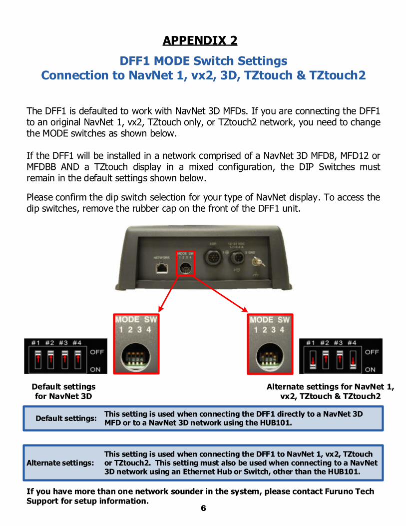
DFF1 MODE Switch SettingsConnection to NavNet 1, vx2, 3D, TZtouch & TZtouch2
The DFF1 is defaulted to work with NavNet 3D MFDs. If you are connecting the DFF1 to an original NavNet 1, vx2, TZtouch only, or TZtouch2 network, you need to change the MODE switches as shown below.
If the DFF1 will be installed in a network comprised of a NavNet 3D MFD8, MFD12 or MFDBB AND a TZtouch display in a mixed configuration, the DIP Switches must remain in the default settings shown below.
Please confirm the dip switch selection for your type of NavNet display. To access the dip switches, remove the rubber cap on the front of the DFF1 unit.
Default settingsfor NavNet 3D
Alternate settings for NavNet 1, vx2, TZtouch & TZtouch2
This setting is used when connecting the DFF1 directly to a NavNet 3D MFD or to a NavNet 3D network using the HUB101.
This setting is used when connecting the DFF1 to NavNet 1, vx2, TZtouch or TZtouch2. This setting must also be used when connecting to a NavNet 3D network using an Ethernet Hub or Switch, other than the HUB101.
Alternate settings:
Default settings:
If you have more than one network sounder in the system, please contact Furuno Tech Support for setup information.
6
APPENDIX 2

If you have more than one network sounder in the system, please contact Furuno Tech Support for setup information.
Only change settings for S2.
Do not change settings for S3.
The DFF3 is defaulted to work with NavNet 3D MFDs. If you are connecting the DFF3 to an original NavNet 1, vx2, TZtouch or TZtouch2 only network, you need to change the MODE switches as shown below.
If the DFF3 will be installed in a mixed system comprised of a NavNet 3D MFD8, MFD12 or MFDBB and either of the TZtouch displays, the DIP Switches must remain in the default settings shown below.
Default settingsfor NavNet 3D
Alternate settings for NavNet 1,vx2, TZtouch & TZtouch2
7
DFF3 MODE Switch Settings
Connection to NavNet 1, vx2, 3D, TZtouch & TZtouch2
APPENDIX 3

When the PSU012 or PSU013 power supply unit is connected to a TZtouch or TZtouch2 MFD, attach the shorting jumper (supplied) to J7 on the PWR Board.
(PSU012 = 03P9481) (PSU013: 03P9483)
8
PSU012/PSU013 Jumper Location for TZtouch & TZtouch2 Installations
APPENDIX 4