installation guide and detailing options for …dutchqualitystone.com/downloads/installation...
TRANSCRIPT
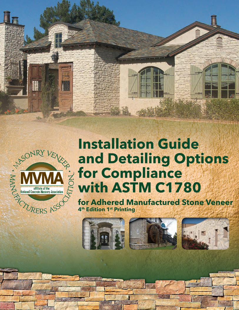
for Adhered Manufactured Stone Veneer4th Edition 1st Printing
Installation Guideand Detailing Optionsfor Compliancewith ASTM C1780

2
Masonry Veneer Manufacturers Associationwww.masonryveneer.org
April 30, 2014 Installation Guide for Adhered Manufactured Stone Veneer, 4th Edition 1st Printing
Table of Contents Definitions/Abbreviations ...................................................................................................................................................................................4
References ..............................................................................................................................................................................................................4
Summary Tables ...................................................................................................................................................................................................5
Workmanship........................................................................................................................................................................................................7
Material Requirements ........................................................................................................................................................................................7
Surface Preparation ..............................................................................................................................................................................................8
Installation of Adhered Manufactured Stone Veneer ....................................................................................................................................10
Cautions ...............................................................................................................................................................................................................12
Drawings / Cross SectionsFigure 1. Installation Over Wood Framing ....................................................................................................................................................13
Figure 2. Installation Over Concrete Masonry Units ..................................................................................................................................14
Figure 3. Wall Assembly ...................................................................................................................................................................................15
Figure 4. Typical Wall Section .........................................................................................................................................................................16
Figure 5. Foundation Wall Base .......................................................................................................................................................................17
Figure 6 . Foundation Wall Base-AMSV Overlapping Foundation .............................................................................................................18
Figure 7. Foundation Wall-Transition to AMSV Continuing Down Foundation ....................................................................................19
Figure 8. Cladding Transition ..........................................................................................................................................................................20
Figure 9. Outside Corner ..................................................................................................................................................................................21
Figure 10. Inside Corner ...................................................................................................................................................................................22
Figure 11. Horizontal Transition ......................................................................................................................................................................23
Figure 12. Vertical Transition ...........................................................................................................................................................................24
Figure 13. Open Eave-Overhang ......................................................................................................................................................................25
Figure 14. Open Eave-Flush ..............................................................................................................................................................................26
Figure 15. Rake-Overhang ................................................................................................................................................................................27
Figure 16. Rake-Flush .......................................................................................................................................................................................28
Figure 17. Side Wall-Composition Shingles ..................................................................................................................................................29
Figure 18. Side Wall-Composition Shingles Curbing ...................................................................................................................................30
Figure 19. Side Wall-Tile Roofing ...................................................................................................................................................................31
Figure 20. Side Wall-Tile Roofing Curbing ....................................................................................................................................................32
Figure 21. Window Sill .....................................................................................................................................................................................33
Figure 22. Window Jamb ..................................................................................................................................................................................34
Figure 23. Window Head..................................................................................................................................................................................35
Figure 24. Kick-Out Flashing ...........................................................................................................................................................................36
Figure 25. Cricket ..............................................................................................................................................................................................37
Figure 26. Chimney Chase ...............................................................................................................................................................................38
Figure 27. Column Base ...................................................................................................................................................................................39
Figure 28. Raised Column Base .......................................................................................................................................................................40
Figure 29. Penetration, Flanged ........................................................................................................................................................................41
3
Masonry Veneer Manufacturers Associationwww.masonryveneer.org
April 30, 2014Installation Guide for Adhered Manufactured Stone Veneer, 4th Edition 1st Printing
Masonry Veneer Manufacturers AssociationNational Concrete Masonry Association13750 Sunrise Valley DriveHerndon, VA 20171Phone: (703) 713-1900www.masonryveneer.orgwww.ncma.org
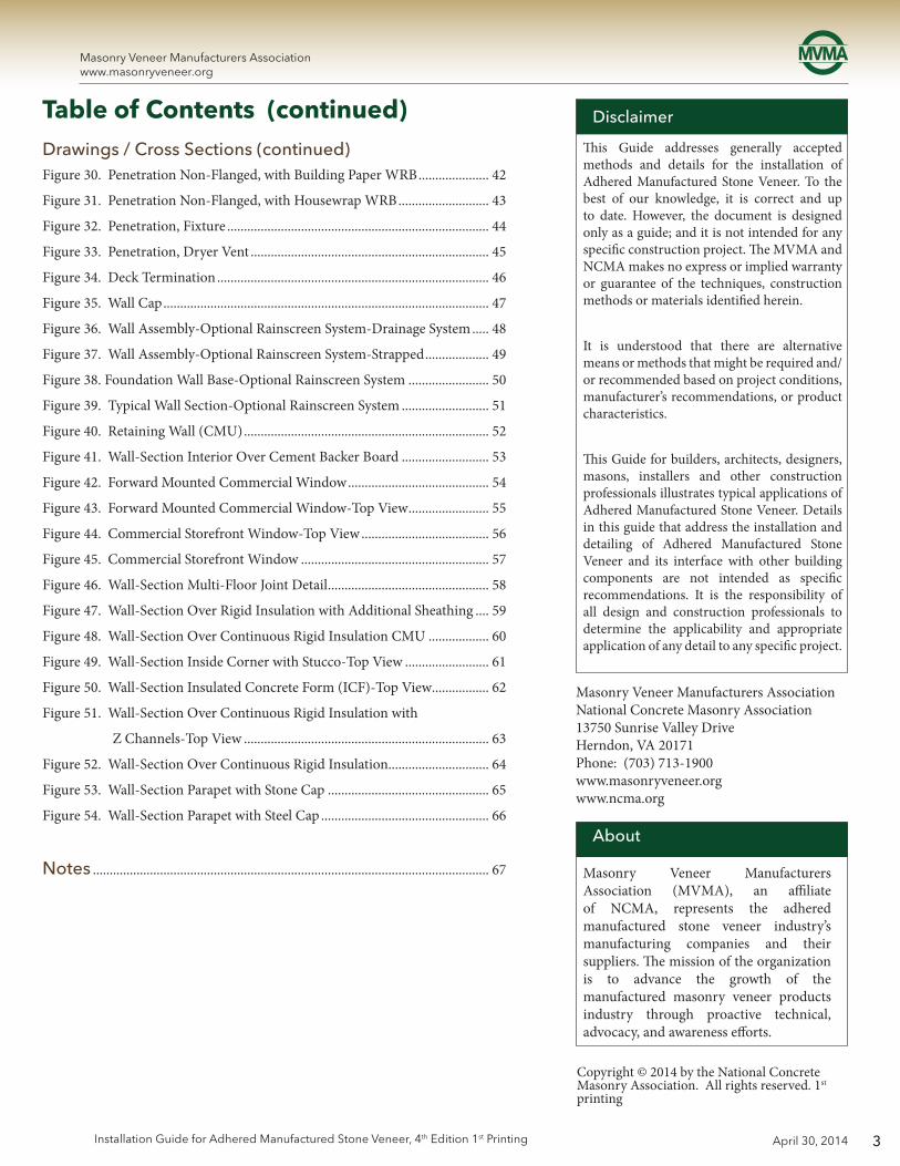
This Guide addresses generally accepted methods and details for the installation of Adhered Manufactured Stone Veneer. To the best of our knowledge, it is correct and up to date. However, the document is designed only as a guide; and it is not intended for any specific construction project. The MVMA and NCMA makes no express or implied warranty or guarantee of the techniques, construction methods or materials identified herein.
It is understood that there are alternative means or methods that might be required and/or recommended based on project conditions, manufacturer’s recommendations, or product characteristics.
This Guide for builders, architects, designers, masons, installers and other construction professionals illustrates typical applications of Adhered Manufactured Stone Veneer. Details in this guide that address the installation and detailing of Adhered Manufactured Stone Veneer and its interface with other building components are not intended as specific recommendations. It is the responsibility of all design and construction professionals to determine the applicability and appropriate application of any detail to any specific project.
Disclaimer
Copyright © 2014 by the National Concrete Masonry Association. All rights reserved. 1st printing
About
Masonry Veneer Manufacturers Association (MVMA), an affiliate of NCMA, represents the adhered manufactured stone veneer industry’s manufacturing companies and their suppliers. The mission of the organization is to advance the growth of the manufactured masonry veneer products industry through proactive technical, advocacy, and awareness efforts.
Table of Contents (continued)Drawings / Cross Sections (continued)Figure 30. Penetration Non-Flanged, with Building Paper WRB ..................... 42
Figure 31. Penetration Non-Flanged, with Housewrap WRB ........................... 43
Figure 32. Penetration, Fixture .............................................................................. 44
Figure 33. Penetration, Dryer Vent ....................................................................... 45
Figure 34. Deck Termination ................................................................................. 46
Figure 35. Wall Cap ................................................................................................. 47
Figure 36. Wall Assembly-Optional Rainscreen System-Drainage System ..... 48
Figure 37. Wall Assembly-Optional Rainscreen System-Strapped ................... 49
Figure 38. Foundation Wall Base-Optional Rainscreen System ........................ 50
Figure 39. Typical Wall Section-Optional Rainscreen System .......................... 51
Figure 40. Retaining Wall (CMU) ......................................................................... 52
Figure 41. Wall-Section Interior Over Cement Backer Board .......................... 53
Figure 42. Forward Mounted Commercial Window .......................................... 54
Figure 43. Forward Mounted Commercial Window-Top View ........................ 55
Figure 44. Commercial Storefront Window-Top View ...................................... 56
Figure 45. Commercial Storefront Window ........................................................ 57
Figure 46. Wall-Section Multi-Floor Joint Detail ................................................ 58
Figure 47. Wall-Section Over Rigid Insulation with Additional Sheathing .... 59
Figure 48. Wall-Section Over Continuous Rigid Insulation CMU .................. 60
Figure 49. Wall-Section Inside Corner with Stucco-Top View ......................... 61
Figure 50. Wall-Section Insulated Concrete Form (ICF)-Top View ................. 62
Figure 51. Wall-Section Over Continuous Rigid Insulation with
Z Channels-Top View ......................................................................... 63
Figure 52. Wall-Section Over Continuous Rigid Insulation.............................. 64
Figure 53. Wall-Section Parapet with Stone Cap ................................................ 65
Figure 54. Wall-Section Parapet with Steel Cap .................................................. 66
Notes ...................................................................................................................... 67
4
Masonry Veneer Manufacturers Associationwww.masonryveneer.org
April 30, 2014 Installation Guide for Adhered Manufactured Stone Veneer, 4th Edition 1st Printing
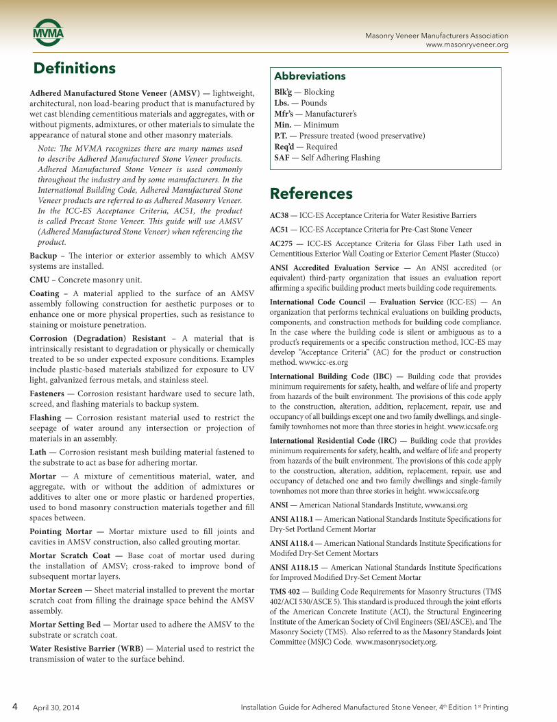
Adhered Manufactured Stone Veneer (AMSV) — lightweight, architectural, non load-bearing product that is manufactured by wet cast blending cementitious materials and aggregates, with or without pigments, admixtures, or other materials to simulate the appearance of natural stone and other masonry materials.
Note: The MVMA recognizes there are many names used to describe Adhered Manufactured Stone Veneer products. Adhered Manufactured Stone Veneer is used commonly throughout the industry and by some manufacturers. In the International Building Code, Adhered Manufactured Stone Veneer products are referred to as Adhered Masonry Veneer. In the ICC-ES Acceptance Criteria, AC51, the product is called Precast Stone Veneer. This guide will use AMSV (Adhered Manufactured Stone Veneer) when referencing the product.
Backup – The interior or exterior assembly to which AMSV systems are installed.CMU – Concrete masonry unit.Coating – A material applied to the surface of an AMSV assembly following construction for aesthetic purposes or to enhance one or more physical properties, such as resistance to staining or moisture penetration.Corrosion (Degradation) Resistant – A material that is intrinsically resistant to degradation or physically or chemically treated to be so under expected exposure conditions. Examples include plastic-based materials stabilized for exposure to UV light, galvanized ferrous metals, and stainless steel.Fasteners — Corrosion resistant hardware used to secure lath, screed, and flashing materials to backup system.Flashing — Corrosion resistant material used to restrict the seepage of water around any intersection or projection of materials in an assembly.Lath — Corrosion resistant mesh building material fastened to the substrate to act as base for adhering mortar.Mortar — A mixture of cementitious material, water, and aggregate, with or without the addition of admixtures or additives to alter one or more plastic or hardened properties, used to bond masonry construction materials together and fill spaces between.Pointing Mortar — Mortar mixture used to fill joints and cavities in AMSV construction, also called grouting mortar.Mortar Scratch Coat — Base coat of mortar used during the installation of AMSV; cross-raked to improve bond of subsequent mortar layers.Mortar Screen — Sheet material installed to prevent the mortar scratch coat from filling the drainage space behind the AMSV assembly.Mortar Setting Bed — Mortar used to adhere the AMSV to the substrate or scratch coat.Water Resistive Barrier (WRB) — Material used to restrict the transmission of water to the surface behind.
Definitions AbbreviationsBlk’g — BlockingLbs. — PoundsMfr’s — Manufacturer’sMin. — MinimumP.T. — Pressure treated (wood preservative)Req’d — RequiredSAF — Self Adhering Flashing
ReferencesAC38 — ICC-ES Acceptance Criteria for Water Resistive Barriers
AC51 — ICC-ES Acceptance Criteria for Pre-Cast Stone Veneer
AC275 — ICC-ES Acceptance Criteria for Glass Fiber Lath used in Cementitious Exterior Wall Coating or Exterior Cement Plaster (Stucco)
ANSI Accredited Evaluation Service — An ANSI accredited (or equivalent) third-party organization that issues an evaluation report affirming a specific building product meets building code requirements.
International Code Council — Evaluation Service (ICC-ES) — An organization that performs technical evaluations on building products, components, and construction methods for building code compliance. In the case where the building code is silent or ambiguous as to a product’s requirements or a specific construction method, ICC-ES may develop “Acceptance Criteria” (AC) for the product or construction method. www.icc-es.org
International Building Code (IBC) — Building code that provides minimum requirements for safety, health, and welfare of life and property from hazards of the built environment. The provisions of this code apply to the construction, alteration, addition, replacement, repair, use and occupancy of all buildings except one and two family dwellings, and single-family townhomes not more than three stories in height. www.iccsafe.org
International Residential Code (IRC) — Building code that provides minimum requirements for safety, health, and welfare of life and property from hazards of the built environment. The provisions of this code apply to the construction, alteration, addition, replacement, repair, use and occupancy of detached one and two family dwellings and single-family townhomes not more than three stories in height. www.iccsafe.org
ANSI — American National Standards Institute, www.ansi.org
ANSI A118.1 — American National Standards Institute Specifications for Dry-Set Portland Cement Mortar
ANSI A118.4 — American National Standards Institute Specifications for Modifed Dry-Set Cement Mortars
ANSI A118.15 — American National Standards Institute Specifications for Improved Modified Dry-Set Cement Mortar
TMS 402 — Building Code Requirements for Masonry Structures (TMS 402/ACI 530/ASCE 5). This standard is produced through the joint efforts of the American Concrete Institute (ACI), the Structural Engineering Institute of the American Society of Civil Engineers (SEI/ASCE), and The Masonry Society (TMS). Also referred to as the Masonry Standards Joint Committee (MSJC) Code. www.masonrysociety.org.
5
Masonry Veneer Manufacturers Associationwww.masonryveneer.org
April 30, 2014Installation Guide for Adhered Manufactured Stone Veneer, 4th Edition 1st Printing
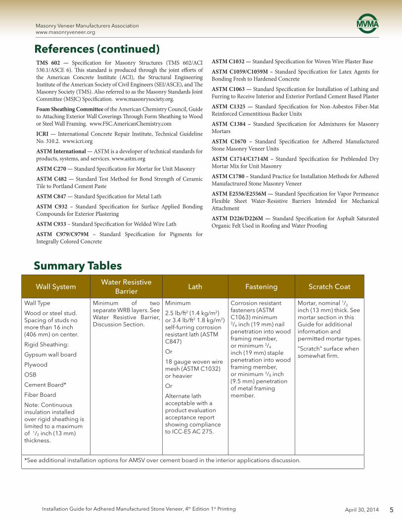
TMS 602 — Specification for Masonry Structures (TMS 602/ACI 530.1/ASCE 6). This standard is produced through the joint efforts of the American Concrete Institute (ACI), the Structural Engineering Institute of the American Society of Civil Engineers (SEI/ASCE), and The Masonry Society (TMS). Also referred to as the Masonry Standards Joint Committee (MSJC) Specification. www.masonrysociety.org.
Foam Sheathing Committee of the American Chemistry Council, Guide to Attaching Exterior Wall Coverings Through Form Sheathing to Wood or Steel Wall Framing. www.FSC.AmericanChemistry.com
ICRI — International Concrete Repair Institute, Technical Guideline No. 310.2. www.icri.org
ASTM International — ASTM is a developer of technical standards for products, systems, and services. www.astm.org
ASTM C270 — Standard Specification for Mortar for Unit Masonry
ASTM C482 — Standard Test Method for Bond Strength of Ceramic Tile to Portland Cement Paste
ASTM C847 — Standard Specification for Metal Lath
ASTM C932 – Standard Specification for Surface Applied Bonding Compounds for Exterior Plastering
ASTM C933 – Standard Specification for Welded Wire Lath
ASTM C979/C979M – Standard Specification for Pigments for Integrally Colored Concrete
References (continued)ASTM C1032 — Standard Specification for Woven Wire Plaster Base
ASTM C1059/C1059M – Standard Specification for Latex Agents for Bonding Fresh to Hardened Concrete
ASTM C1063 — Standard Specification for Installation of Lathing and Furring to Receive Interior and Exterior Portland Cement Based Plaster
ASTM C1325 — Standard Specification for Non-Asbestos Fiber-Mat Reinforced Cementitious Backer Units
ASTM C1384 – Standard Specification for Admixtures for Masonry Mortars
ASTM C1670 – Standard Specification for Adhered Manufactured Stone Masonry Veneer Units
ASTM C1714/C1714M – Standard Specification for Preblended Dry Mortar Mix for Unit Masonry
ASTM C1780 – Standard Practice for Installation Methods for Adhered Manufactrured Stone Masonry Veneer
ASTM E2556/E2556M — Standard Specification for Vapor Permeance Flexible Sheet Water-Resistive Barriers Intended for Mechanical Attachment
ASTM D226/D226M — Standard Specification for Asphalt Saturated Organic Felt Used in Roofing and Water Proofing
Summary Tables
Wall SystemWater Resistive
BarrierLath Fastening Scratch Coat
Wall Type
Wood or steel stud. Spacing of studs no more than 16 inch (406 mm) on center.
Rigid Sheathing:
Gypsum wall board
Plywood
OSB
Cement Board*
Fiber Board
Note: Continuous insulation installed over rigid sheathing is limited to a maximum of 1/2 inch (13 mm) thickness.
Minimum of two separate WRB layers. See Water Resistive Barrier, Discussion Section.
Minimum
2.5 lb/ft2 (1.4 kg/m2) or 3.4 lb/ft2 1.8 kg/m2) self-furring corrosion resistant lath (ASTM C847)
Or
18 gauge woven wire mesh (ASTM C1032) or heavier
Or
Alternate lath acceptable with a product evaluation acceptance report showing compliance to ICC-ES AC 275.
Corrosion resistant fasteners (ASTM C1063) minimum 3/4 inch (19 mm) nail penetration into wood framing member, or minimum 3/4 inch (19 mm) staple penetration into wood framing member, or minimum 3/8 inch (9.5 mm) penetration of metal framing member.
Mortar, nominal 1/2 inch (13 mm) thick. See mortar section in this Guide for additional information and permitted mortar types.
“Scratch” surface when somewhat firm.
*See additional installation options for AMSV over cement board in the interior applications discussion.

6
Masonry Veneer Manufacturers Associationwww.masonryveneer.org
April 30, 2014 Installation Guide for Adhered Manufactured Stone Veneer, 4th Edition 1st Printing
Wall SystemWater Resistive
BarrierLath Fastening Scratch Coat
Clean Concrete, Masonry / CMU, Stucco Scratch Coat (1st layer of cement plaster), or Stucco Brown Coat (2nd layer of cement plaster).
Note: walls / surfaces must be clean and free from release agents, paints, stains, sealers, or other bond-break materials that may reduce strength of mortar adhesion.
Note: A WRB may be needed to prevent moisture from penetrating the wall.
Install lath if there is a question or concern regarding ability of veneer to adhere to wall (see additional discussion under Surface Preparation Section):
2.5 lb (1.1 kg) or 3.4 lb (1.5 kg) self-furring 3/8 inch (9.5 mm) ribbed corrosion-resistant lath (ASTM C 847 )
Or
18 gauge woven wire mesh (ASTM C 1032)
Alternate lath acceptable with a product evaluation acceptance report showing compliance to ICC-ES AC 275.
If lath is applied, use corrosion resistant fasteners (ASTM 1063).
If a scratch coat is required use a nominal 1/2 inch (13 mm) thick. See mortar section in this Guide for additional information and permitted mortar types.
“Scratch” surface when somewhat firm.
Summary Tables (continued)
Wall SystemWater Resistive
BarrierLath Fastening Scratch Coat
Existing Concrete, Masonry / CMU, Stucco, or Brick (structurally sound) (e.g. painted or not clean)
If the wall system is effectively cleaned and with adequate surface roughness, see the table above.
Note: A WRB may be needed to prevent moisture from penetrating the wall.
2.5 lb (1.1 kg) or 3.4 lb (1.5 kg) self-furring 3/8 inch (9.5 mm) ribbed corrosion-resistant lath (ASTM C847)
Or
18 gauge woven wire mesh (ASTM C1032)
Alternate lath acceptable with a product evaluation acceptance report showing compliance to ICC-ES AC 275.
Use corrosion resistant fasteners (ASTM C1063).
Nominal 1/2 inch (13 mm) thick. See mortar section in this Guide for additional information and permitted mortar types.
“Scratch” surface when somewhat firm.
Wall SystemWater Resistive
BarrierLath Fastening Scratch Coat
Metal Buildings or other surfaces / wall construction not listed above. See manufacturer for recommendations regarding sheathing.
See manufacturer for recommendations.

7
Masonry Veneer Manufacturers Associationwww.masonryveneer.org
April 30, 2014Installation Guide for Adhered Manufactured Stone Veneer, 4th Edition 1st Printing
This guide focuses on the installation of AMSV systems for backup assemblies addressed in the tables above. Other backup systems, such as structural insulated panels (SIPs), may require a specifically-designed system of installation for AMSVs. AMSV systems should not be installed over deteriorating or unsound backup assemblies or exterior insulation and finishing systems (EIFS).
WorkmanshipThis Installation Guide assumes that construction personnel have knowledge of the materials described and their proper methods of installation.
Prior to commencing activity related to the scope of this Guide, review all adjacent products and other work that precedes the installation of AMSV to ensure that proper workmanship is reflected and that there are no recognizable errors or deficiencies.
Quality
A successful project requires the use of quality materials, proper detailing for the application, and a high standard of care during installation. Unfortunately, the execution of these components in the field can be subject to value-engineering resulting in materials being selected based solely on price and installation techniques that focus on speed rather than quality. While the performance of AMSV systems depends upon all three of these components, field workmanship issues tend to be the dominate source of problems when performance issues surface in the field. Installing AMSV in accordance with the recommended practices of this guide and ASTM 1780 helps to ensure AMSV systems perform as intended for decades.
Building Code RequirementsBuilding code requirements vary from area to area. Check with local authorities for building code requirements for your area and application. Carefully read all sections of this guide and follow the manufacturer’s installation instructions before proceeding with your AMSV application. In the event the manufacturer’s installation instructions conflict with the intent of statements made in this document, contact the manufacturer for additional guidance.
Project Site RequirementsJobsite safety is outside of the scope of this guide, however, users should always follow proper job site safety requirements including local, state, and federal laws when installing AMSV products and systems.
Material RequirementsFlashing All flashing and flashing accessories must be corrosion resistant and integrated with the WRB materials (if present). For exterior
applications flashing must be installed at all through wall penetrations and at terminations of AMSV installations. Flashing is not required for interior applications of AMSV systems not exposed to water. For interior applications that are exposed to water, treat as an exterior assembly.
Rainscreen Drainage Plane SystemsRainscreens are optional building techniques that are used to improve the drainage of incidental water behind the cladding and reduce drying time. Rainscreen products (such as drainage mats or formed polymer sheeting) or construction techniques (such as strapping or furring) that create a capillary break/air space between the cladding and the primary water resistive barrier can be effectively incorporated into AMSV applications. Refer to the manufacturer’s recommendation for rainscreen / drainage system applications with adhered manufactured stone veneer wall systems. Building codes may allow a single layer of a water resistive barrier when a drainage space is incorporated in the wall system (i.e. rainscreen). Requirements for rainscreens vary by region. Verify local jurisdictional requirements regarding the use and application of rainscreens.
Weep Screeds and Casing Beads Weep screeds and casing beads must be corrosion resistant, with weep screeds having a minimum vertical attachment flange of 3.5 inches (89 mm) that terminates behind the water resistive barrier (if present). The minimum thickness of metal weep screeds and casing beads should not be less than 0.0179 inches (0.45 mm) (26 gage) or less than 0.050 inches (1.3 mm) for plastic weep screeds or casing beads.
Lath Multiple lath materials have been used successfully for the installation of AMSV systems, including:
• 2.5 lb/yd2 (1.4 kg/m2) (or heavier) self-furring metal lath meeting ASTM C847;
• 3/8 inch (9.5 mm) rib (high rib), 3.4 lb/yd2 (1.8 kg/m2) (or heavier), self-furring metal lath meeting ASTM C847;
• WeldedwirelathcomplyingwithASTMC933;
• 18gauge(orheavier)wovenwiremeshmeetingASTMC1032;or
• ThelathproductisconsistentwiththeAMSVmanufacturer’sinstallation instructions and has an evaluation acceptance report from an accredited evaluation service showing compliance with ICC-ES Acceptance Criteria 275 (AC275), or equivalent.
All lath and lath accessories must be corrosion resistant, consisting of either galvanized or stainless steel materials or consisting of materials complying with AC 275. All lath material must be self-furred or use self-furring fasteners. Refer to the Summary Table of this guide for specific lath and fastener recommendations.
Fasteners Corrosion resistant fasteners are used to secure flashing and lath to the backup system. A variety of fasteners are available
8
Masonry Veneer Manufacturers Associationwww.masonryveneer.org
April 30, 2014 Installation Guide for Adhered Manufactured Stone Veneer, 4th Edition 1st Printing
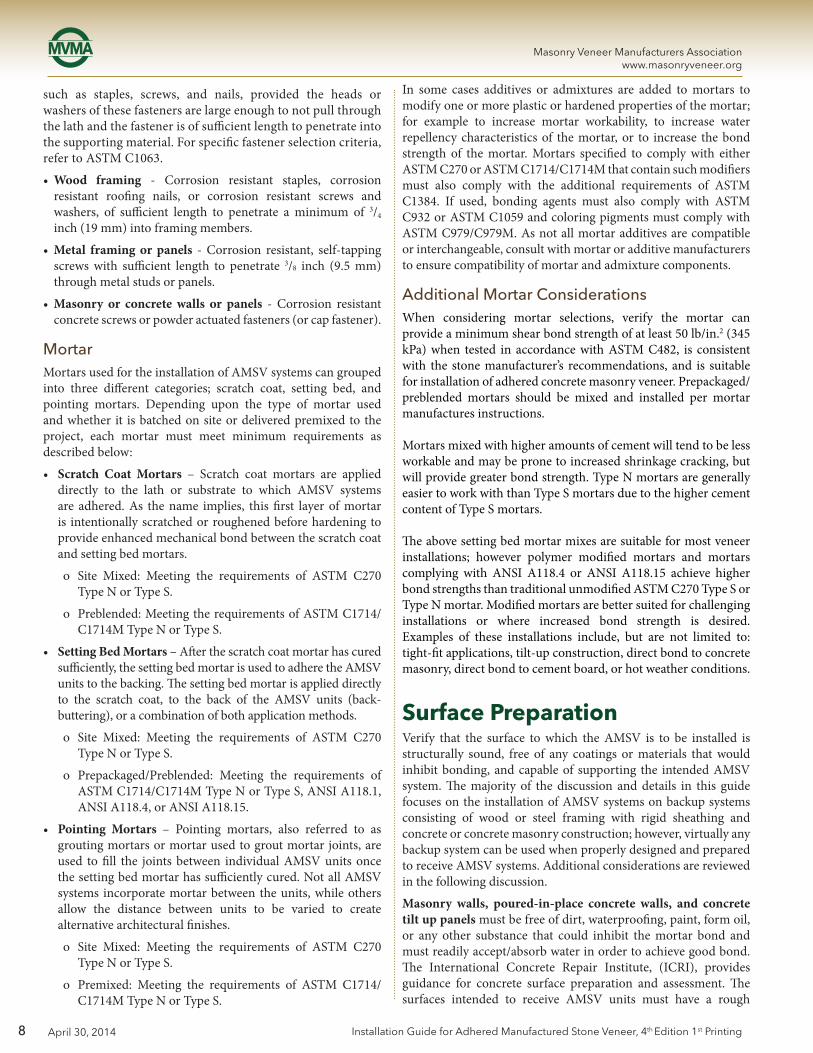
such as staples, screws, and nails, provided the heads or washers of these fasteners are large enough to not pull through the lath and the fastener is of sufficient length to penetrate into the supporting material. For specific fastener selection criteria, refer to ASTM C1063.
• Wood framing - Corrosion resistant staples, corrosion resistant roofing nails, or corrosion resistant screws and washers, of sufficient length to penetrate a minimum of 3/4 inch (19 mm) into framing members.
• Metal framing or panels - Corrosion resistant, self-tapping screws with sufficient length to penetrate 3/8 inch (9.5 mm) through metal studs or panels.
• Masonry or concrete walls or panels - Corrosion resistant concrete screws or powder actuated fasteners (or cap fastener).
Mortar Mortars used for the installation of AMSV systems can grouped into three different categories; scratch coat, setting bed, and pointing mortars. Depending upon the type of mortar used and whether it is batched on site or delivered premixed to the project, each mortar must meet minimum requirements as described below:
• Scratch Coat Mortars – Scratch coat mortars are applied directly to the lath or substrate to which AMSV systems are adhered. As the name implies, this first layer of mortar is intentionally scratched or roughened before hardening to provide enhanced mechanical bond between the scratch coat and setting bed mortars.
o Site Mixed: Meeting the requirements of ASTM C270 Type N or Type S.
o Preblended: Meeting the requirements of ASTM C1714/C1714M Type N or Type S.
• Setting Bed Mortars – After the scratch coat mortar has cured sufficiently, the setting bed mortar is used to adhere the AMSV units to the backing. The setting bed mortar is applied directly to the scratch coat, to the back of the AMSV units (back-buttering), or a combination of both application methods.
o Site Mixed: Meeting the requirements of ASTM C270 Type N or Type S.
o Prepackaged/Preblended: Meeting the requirements of ASTM C1714/C1714M Type N or Type S, ANSI A118.1, ANSI A118.4, or ANSI A118.15.
• Pointing Mortars – Pointing mortars, also referred to as grouting mortars or mortar used to grout mortar joints, are used to fill the joints between individual AMSV units once the setting bed mortar has sufficiently cured. Not all AMSV systems incorporate mortar between the units, while others allow the distance between units to be varied to create alternative architectural finishes.
o Site Mixed: Meeting the requirements of ASTM C270 Type N or Type S.
o Premixed: Meeting the requirements of ASTM C1714/C1714M Type N or Type S.
In some cases additives or admixtures are added to mortars to modify one or more plastic or hardened properties of the mortar; for example to increase mortar workability, to increase water repellency characteristics of the mortar, or to increase the bond strength of the mortar. Mortars specified to comply with either ASTM C270 or ASTM C1714/C1714M that contain such modifiers must also comply with the additional requirements of ASTM C1384. If used, bonding agents must also comply with ASTM C932 or ASTM C1059 and coloring pigments must comply with ASTM C979/C979M. As not all mortar additives are compatible or interchangeable, consult with mortar or additive manufacturers to ensure compatibility of mortar and admixture components.
Additional Mortar ConsiderationsWhen considering mortar selections, verify the mortar can provide a minimum shear bond strength of at least 50 lb/in.2 (345 kPa) when tested in accordance with ASTM C482, is consistent with the stone manufacturer’s recommendations, and is suitable for installation of adhered concrete masonry veneer. Prepackaged/preblended mortars should be mixed and installed per mortar manufactures instructions.
Mortars mixed with higher amounts of cement will tend to be less workable and may be prone to increased shrinkage cracking, but will provide greater bond strength. Type N mortars are generally easier to work with than Type S mortars due to the higher cement content of Type S mortars.
The above setting bed mortar mixes are suitable for most veneer installations; however polymer modified mortars and mortars complying with ANSI A118.4 or ANSI A118.15 achieve higher bond strengths than traditional unmodified ASTM C270 Type S or Type N mortar. Modified mortars are better suited for challenging installations or where increased bond strength is desired. Examples of these installations include, but are not limited to: tight-fit applications, tilt-up construction, direct bond to concrete masonry, direct bond to cement board, or hot weather conditions.
Surface PreparationVerify that the surface to which the AMSV is to be installed is structurally sound, free of any coatings or materials that would inhibit bonding, and capable of supporting the intended AMSV system. The majority of the discussion and details in this guide focuses on the installation of AMSV systems on backup systems consisting of wood or steel framing with rigid sheathing and concrete or concrete masonry construction; however, virtually any backup system can be used when properly designed and prepared to receive AMSV systems. Additional considerations are reviewed in the following discussion.
Masonry walls, poured-in-place concrete walls, and concrete tilt up panels must be free of dirt, waterproofing, paint, form oil, or any other substance that could inhibit the mortar bond and must readily accept/absorb water in order to achieve good bond. The International Concrete Repair Institute, (ICRI), provides guidance for concrete surface preparation and assessment. The surfaces intended to receive AMSV units must have a rough

9
Masonry Veneer Manufacturers Associationwww.masonryveneer.org
April 30, 2014Installation Guide for Adhered Manufactured Stone Veneer, 4th Edition 1st Printing
texture to ensure good mortar bond. Refer to ICRI Technical Guideline 310.2 for additional information on concrete surface preparation, including information on Concrete Surface Profile (CSP), a standardized method to measure concrete surface roughness. A CSP equal to or greater than 2 is usually acceptable for the installation of AMSV over concrete and masonry assemblies. If necessary, cleaning may be done with power washing or mechanical methods (i.e. shot or bead blasting). If a bondable surface cannot be achieved, attach lath and scratch coat before installing AMSV.
This guide does not address the installation of AMSV systems over open stud backup systems. Additional information on the use of AMSV systems in conjuction with open stud construction is available in previous editions of this guide.
Wall Systems with Exterior Continuous InsulationAMSV may be installed on walls insulated with continuous insulation such as foam insulation. Lath attachment methods described in this guide are generally considered acceptable when AMSV is installed over continuous insulation up to 1/2 inch (13 mm) thick. Installation of AMSV over continuous insulation greater than 1/2 inch (13 mm) thick generally requires an engineered fastening system.
The Foam Sheathing Committee of the American Chemistry Council (www.americanchemistry.com) has published a "Guide to Attaching Exterior Wall Coverings through Foam Sheathing to Wood or Steel Wall Framing" that may provide guidance when engineering a fastening system for AMSV (http://fsc.americanchemistry.com/Building-Code/Installation-of-Cladding/Guide-to-Attaching-Exterior-Wall-Coverings.pdf).
Water Resistive BarrierWhere a water resistive barrier (WRB) is required, it should be installed in two separate layers in shingle fashion, starting from the bottom of the wall. The inner layer of WRB should be installed, along with flashings, to create a drainage plane. The outer layer of WRB is intended to keep the scratch coat from contacting the inner layer of WRB. The upper layer of the WRB should lap on top of the lower layer by a minimum of 2 inches (51 mm). The vertical joints of the WRB should be lapped a minimum of 6 inches (152 mm). Inside and outside corners must be overlapped a minimum of 16 inches (406 mm) past the corner in both directions. The WRB should be installed in accordance with the manufacturer’s recommendations and be integrated with all flashing accessories, adjacent WRBs, doors, windows, penetrations, and cladding transitions.
Acceptable WRBs:
• Minimumtwoseparate layersof anyof the following:No.15felt complying with ASTM D226 for Type 1 felt, Grade D paper complying with ICC-ES AC38, house wrap complying with ICC-ES AC38, WR complying with ASTM E2556/E2556M, or any combination of two separate layers of these materials. One layer of paper-backed lath meeting requirements for Grade D paper may be substituted for the outer layer.
• Continuousinsulationmaybesubstitutedfortheinnerlayerof WRB provided it is installed and sealed and/or taped in accordance with the insulation manufacturer's installation instructions and has an evaluation service report from an accredited evaluation service recognizing it as a WRB. Continuous insulation is commonly applied on the exterior side of the framing or on the exterior side of sheathing, runs continuously, and has minimal thermal bridging. Ensure WRB(s) selected are intended for wall applications. Some WRB's intended for roofs are not appropriate for walls. For example, 15 pound felt is not the same product as No. 15 felt.
LathMetal lath should be applied horizontally (perpendicular to framing, if present) per manufacturer’s instructions, and should overlap a minimum of 1 inch (25 mm) at the horizontal and vertical seams. The ends of adjoining lath places should be staggered. Metal lath is usually installed with the lath "cups" (keys) facing up. With the cups up, the lath feels rough when sliding the hand vertically down the wall, and feels smooth when sliding the hand up the lath.
Lath should be wrapped around inside and outside corners a minimum of 12 inches (305 mm). Lath should be fastened every 6 inches (152 mm) vertically on each stud or similar spacing on concrete or masonry wall surfaces. Do not end lath at corner framing.
Alternate lath should be installed per the manufacturer’s instructions.
Flashings/Weep Screeds/Casing Bead/Movement JointsAll flashing and accessory detailing pieces should be corrosion resistant.
Verify that all flashing, including roofing kickout flashing, has been properly installed. Although roof flashings are not part of the wall cladding system, they are necessary for proper water management. Flashing material should extend above horizontal terminations, roofing material, and drainage planes or drainage products.
All flashing material should be integrated with water resistive barriers to prevent water penetration into structure. The WRB should overlap the weep screed flange.
Movement Joints - Different elements and materials within any structure move differently in response to applied loads or as a result of fluctuations in temperature or moisture content. In determining if and where movement joints may be needed as part of an AMSV installation, consideration should be given to where differential movement is expected—for example, at the intersection of dissimilar materials; or where movement may be concentrated—for example, at the transition between a framed backup assembly and a concrete masonry assembly. Additional information is available in "Are Control Joints Needed with Adhered Concrete Masonry Veneer" through MVMA's website: www.masonryveneer.org.
10
Masonry Veneer Manufacturers Associationwww.masonryveneer.org
April 30, 2014 Installation Guide for Adhered Manufactured Stone Veneer, 4th Edition 1st Printing
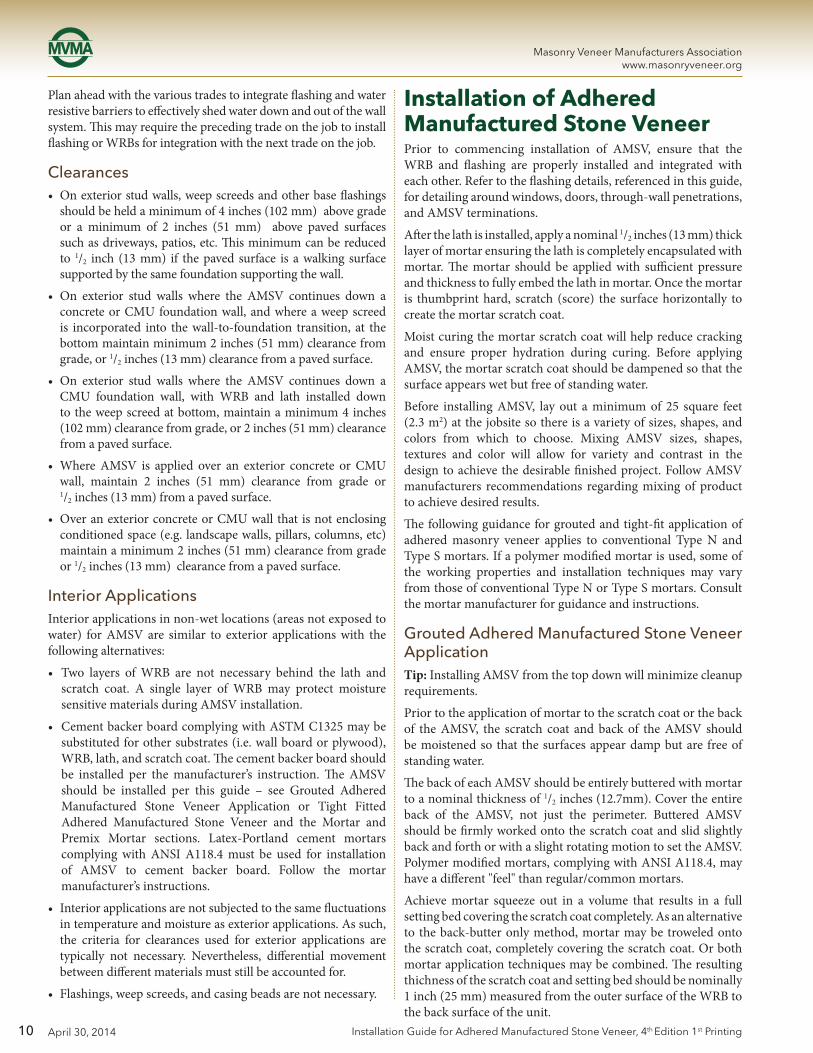
Plan ahead with the various trades to integrate flashing and water resistive barriers to effectively shed water down and out of the wall system. This may require the preceding trade on the job to install flashing or WRBs for integration with the next trade on the job.
Clearances • Onexteriorstudwalls,weepscreedsandotherbaseflashings
should be held a minimum of 4 inches (102 mm) above grade or a minimum of 2 inches (51 mm) above paved surfaces such as driveways, patios, etc. This minimum can be reduced to 1/2 inch (13 mm) if the paved surface is a walking surface supported by the same foundation supporting the wall.
• On exterior stud walls where the AMSV continues down aconcrete or CMU foundation wall, and where a weep screed is incorporated into the wall-to-foundation transition, at the bottom maintain minimum 2 inches (51 mm) clearance from grade, or 1/2 inches (13 mm) clearance from a paved surface.
• On exterior stud walls where the AMSV continues down aCMU foundation wall, with WRB and lath installed down to the weep screed at bottom, maintain a minimum 4 inches (102 mm) clearance from grade, or 2 inches (51 mm) clearance from a paved surface.
• WhereAMSV is applied over an exterior concrete orCMUwall, maintain 2 inches (51 mm) clearance from grade or 1/2 inches (13 mm) from a paved surface.
• OveranexteriorconcreteorCMUwallthatisnotenclosingconditioned space (e.g. landscape walls, pillars, columns, etc) maintain a minimum 2 inches (51 mm) clearance from grade or 1/2 inches (13 mm) clearance from a paved surface.
Interior ApplicationsInterior applications in non-wet locations (areas not exposed to water) for AMSV are similar to exterior applications with the following alternatives:
• Two layers ofWRB are not necessary behind the lath andscratch coat. A single layer of WRB may protect moisture sensitive materials during AMSV installation.
• CementbackerboardcomplyingwithASTMC1325maybesubstituted for other substrates (i.e. wall board or plywood), WRB, lath, and scratch coat. The cement backer board should be installed per the manufacturer’s instruction. The AMSV should be installed per this guide – see Grouted Adhered Manufactured Stone Veneer Application or Tight Fitted Adhered Manufactured Stone Veneer and the Mortar and Premix Mortar sections. Latex-Portland cement mortars complying with ANSI A118.4 must be used for installation of AMSV to cement backer board. Follow the mortar manufacturer’s instructions.
• Interior applications are not subjected to the same fluctuations in temperature and moisture as exterior applications. As such, the criteria for clearances used for exterior applications are typically not necessary. Nevertheless, differential movement between different materials must still be accounted for.
• Flashings,weepscreeds,andcasingbeadsarenotnecessary.
Installation of Adhered Manufactured Stone VeneerPrior to commencing installation of AMSV, ensure that the WRB and flashing are properly installed and integrated with each other. Refer to the flashing details, referenced in this guide, for detailing around windows, doors, through-wall penetrations, and AMSV terminations.
After the lath is installed, apply a nominal 1/2 inches (13 mm) thick layer of mortar ensuring the lath is completely encapsulated with mortar. The mortar should be applied with sufficient pressure and thickness to fully embed the lath in mortar. Once the mortar is thumbprint hard, scratch (score) the surface horizontally to create the mortar scratch coat.
Moist curing the mortar scratch coat will help reduce cracking and ensure proper hydration during curing. Before applying AMSV, the mortar scratch coat should be dampened so that the surface appears wet but free of standing water.
Before installing AMSV, lay out a minimum of 25 square feet (2.3 m2) at the jobsite so there is a variety of sizes, shapes, and colors from which to choose. Mixing AMSV sizes, shapes, textures and color will allow for variety and contrast in the design to achieve the desirable finished project. Follow AMSV manufacturers recommendations regarding mixing of product to achieve desired results.
The following guidance for grouted and tight-fit application of adhered masonry veneer applies to conventional Type N and Type S mortars. If a polymer modified mortar is used, some of the working properties and installation techniques may vary from those of conventional Type N or Type S mortars. Consult the mortar manufacturer for guidance and instructions.
Grouted Adhered Manufactured Stone Veneer ApplicationTip: Installing AMSV from the top down will minimize cleanup requirements.
Prior to the application of mortar to the scratch coat or the back of the AMSV, the scratch coat and back of the AMSV should be moistened so that the surfaces appear damp but are free of standing water.
The back of each AMSV should be entirely buttered with mortar to a nominal thickness of 1/2 inches (12.7mm). Cover the entire back of the AMSV, not just the perimeter. Buttered AMSV should be firmly worked onto the scratch coat and slid slightly back and forth or with a slight rotating motion to set the AMSV. Polymer modified mortars, complying with ANSI A118.4, may have a different "feel" than regular/common mortars.
Achieve mortar squeeze out in a volume that results in a full setting bed covering the scratch coat completely. As an alternative to the back-butter only method, mortar may be troweled onto the scratch coat, completely covering the scratch coat. Or both mortar application techniques may be combined. The resulting thichness of the scratch coat and setting bed should be nominally 1 inch (25 mm) measured from the outer surface of the WRB to the back surface of the unit.

11
Masonry Veneer Manufacturers Associationwww.masonryveneer.org
April 30, 2014Installation Guide for Adhered Manufactured Stone Veneer, 4th Edition 1st Printing
With the proper mortar mix, moisture content, and scratch coat preparation, the installer will feel the mortar start to grab within a few seconds of the setting movement process. At this point, no further movement of that AMSV should be made as bonding will be broken. If the AMSV is inadvertently moved after initial set has begun, it should be removed, mortar scraped off the back of the AMSV and scratch coat, and then reinstalled following the application process.
Grouting the joints should be completed only after there is sufficient cure time of the installed AMSV units; when mild contact with AMSV units will not break the bond to the backup system. Grouting may be done with a grout bag, filling joints to the desired depth, ensuring that mortar is forced into all voids. Grout should be “thumbprint hard” before tooling the joints. The curing time required before the grout is ready will vary significantly with temperature and humidity. Use a wooden raking stick or pointing tool to tool the joints to the desired depth. Extra precaution should be taken while tooling so the surface of the AMSV is not damaged. Clean off remaining grout debris on the AMSV surface with a dry, soft-bristled brush.
To prevent mortar smearing, DO NOT use a wet brush to treat uncured mortar joints.
Tight Fitted Adhered Manufactured Stone Veneer ApplicationRefer to Mortar section for additional guidance regarding mortar selection. For this installation technique, refer to the Additional Mortar Considerations section.
The back of the AMSV and the scratch coat should be moistened with the surfaces appearing damp but free of standing water.
The back of each AMSV should be entirely buttered with mortar to a nominal thickness of 1/2 inch (13 mm). Cover the entire back of the AMSV, not just the perimeter. Buttered AMSV should be firmly worked onto the scratch coat and slid slightly back and forth to set the AMSV.
Achieve mortar squeeze out in a volume that results in a full setting bed which covers the scratch coat completely. As an alternative to the back-butter only method, mortar may be troweled onto the scratch coat, completely covering the scratch coat. Or both mortar application techniques may be combined. The resulting thichness of the scratch coat and setting bed should be nominally 1 inch (25 mm) measured from the outer surface of the WRB to the back surface of the unit.
With the proper mortar mix, moisture content and scratch coat preparation, the installer will feel the mortar start to grab within a few seconds of the setting movement process. At this point, no further movement of that AMSV should be made as bonding will be broken. If the AMSV is inadvertently moved after initial set has begun, it should be removed, mortar scraped off the back of the AMSV and scratch coat, and then reinstalled following the application process.
Tight fitted AMSV should be applied from the corners toward the middle of a wall, and from the bottom toward the top of the wall.
Cold Weather ApplicationAMSV applications should be protected from temperatures below 40°F (4°C) during and immediately following installation. The use of anti-freeze admixtures to lower the freezing point of the mortar is not recommended. Accelerating admixtures shall comply with ASTM C1384; accelerating admixtures containing calcium chloride are not recommended. AMSV pieces containing visible frozen moisture shall not be installed.
The cold weather practices defined in TMS 602 should be followed for the installation of AMSV systems.
Hot Weather Application If the environmental conditions during installation exceed 90°F (32°C) additional water may be needed on the scratch coat surface and the backs of the AMSV being applied. Providing shade and/or frequent misting of the wall may be required. Consult with mortar manufacturer to determine if hot weather mortar mix options are available. The hot weather practices defined in TMS 602 should be followed for the installation of AMSV systems.
Cleaning the Adhered Manufactured Stone Veneer Refer to AMSV manufacturer recommendations on cleaning and maintenance. Do not use harsh chemicals for cleaning, such as acid, or use abrasive tools such as wire brushes or power washers.
Coating Adhered Manufactured Stone Veneer Refer to the AMSV manufacturer for recommendations regarding the use of sealants or other topically applied coatings used for water penetration resistance, graffiti resistance, or surface sealing.
Alternative Installation Methods / MaterialsThis guide covers common installation practices for AMSV systems. Alternative installation materials and methods not included in this guide may be introduced into the marketplace. Example: Exterior installation methods using cementitious adhesive mortars with a direct application to a substrate that may include cement board and / or coatings applied as loadbearing bonded water-proof membranes.
Alternative installation materials and methods along with their test methods and evaluation criteria are being developed. As a designer, contractor, or installer, you may wish to utilize these materials and/or methods in lieu of the resommended methods included in this guide. Users should verify that the alternative method(s) will meet or exceed the recommended installation practices presented in this guide.
12
Masonry Veneer Manufacturers Associationwww.masonryveneer.org
April 30, 2014 Installation Guide for Adhered Manufactured Stone Veneer, 4th Edition 1st Printing
Refer to manufacturer's recommendations for additional information regarding the use of alternative installation methods or materials.
CautionsThe following precautions should be taken to ensure a successful and durable AMSV installation.
• DonotsubjectAMSVtodirectorfrequentwatercontact.For example, avoid allowing sprinklers to directly spray onto the surface. Also, downspouts or drainage pipes should be placed so that water is not frequently moistening the AMSV units.
• Do not subject AMSV to contact with de-icing materials,salt, or other harsh chemicals. Prolonged exposure to these conditions may discolor the AMSV or result in surface damage.

13
Masonry Veneer Manufacturers Associationwww.masonryveneer.org
April 30, 2014Installation Guide for Adhered Manufactured Stone Veneer, 4th Edition 1st Printing
Figure 1. Installation Over Wood Framing
INTERIOR GYPSUM BOARD
BATT INSULATION
WOOD FRAMING
EXTERIOR GRADE SHEATHING
(2) LAYERS OF WRB
LATH
LATH FASTENERS - TYPE & SPACING PER ASTM C1063
MORTAR SCRATCH COAT
MORTAR SETTING BED
ADHERED CONCRETE MASONRY VENEER
MORTAR JOINT
WRB LAPPED OVER WEEP SCREED
WEEP SCREED

14
Masonry Veneer Manufacturers Associationwww.masonryveneer.org
April 30, 2014 Installation Guide for Adhered Manufactured Stone Veneer, 4th Edition 1st Printing
Figure 2. Installation Over Concrete Masonry Units
INTERIOR GYPSUM BOARD
FURRING OR CHANNEL
RIGID INSULATION
JOINT REINFORCEMENT
CMU BACKUP
LATH (OPTIONAL)
LATH FASTENER - TYPE & SPACING PER ASTM C1063
MORTAR SCRATCH COAT
MORTAR SETTING BED
ADHERED CONCRETE MASONRY VENEER
MORTARJOINT
WEEP SCREED (OPTIONAL)
15
Masonry Veneer Manufacturers Associationwww.masonryveneer.org
April 30, 2014Installation Guide for Adhered Manufactured Stone Veneer, 4th Edition 1st Printing
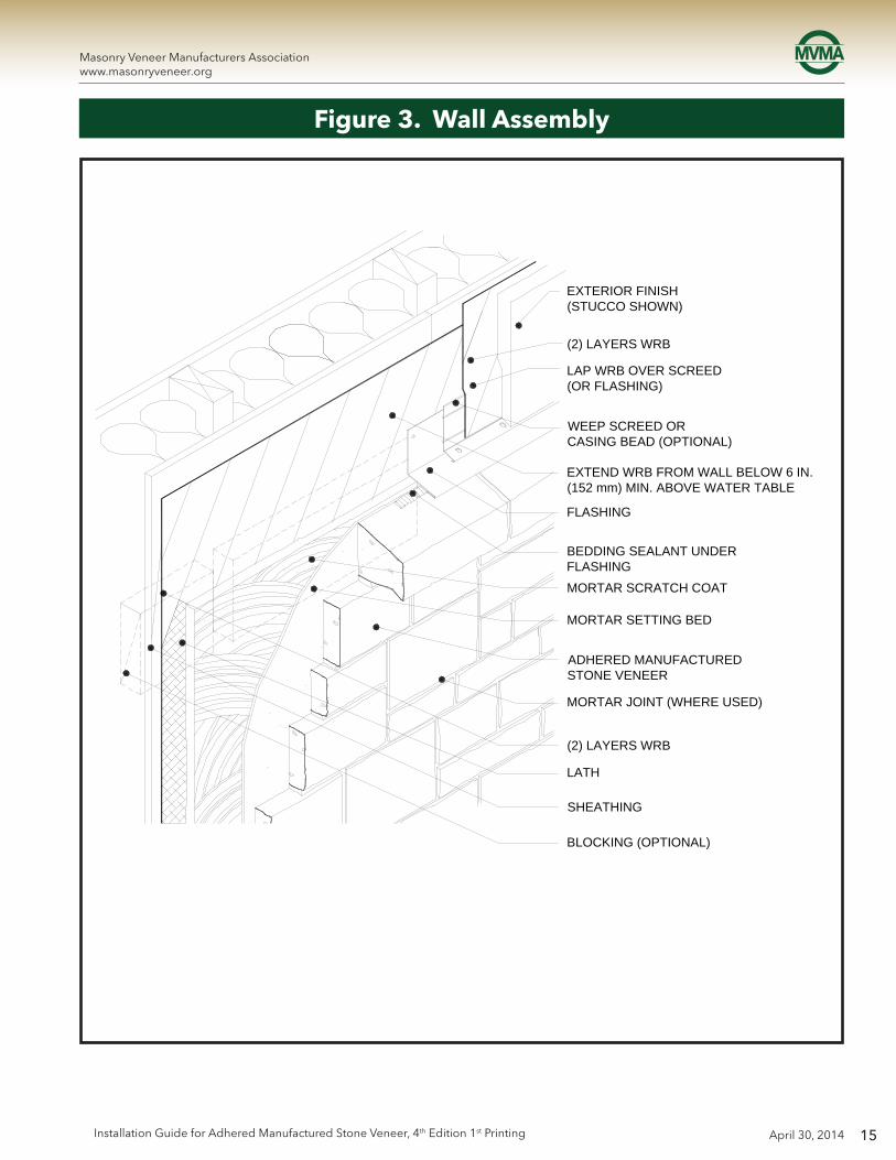
Figure 3. Wall Assembly
EXTERIOR FINISH(STUCCO SHOWN)
(2) LAYERS WRB
LAP WRB OVER SCREED(OR FLASHING)
WEEP SCREED ORCASING BEAD (OPTIONAL)
EXTEND WRB FROM WALL BELOW 6 IN.(152 mm) MIN. ABOVE WATER TABLE
FLASHING
BEDDING SEALANT UNDERFLASHINGMORTAR SCRATCH COAT
MORTAR SETTING BED
ADHERED MANUFACTURED STONE VENEER
MORTAR JOINT (WHERE USED)
(2) LAYERS WRB
LATH
SHEATHING
BLOCKING (OPTIONAL)

16
Masonry Veneer Manufacturers Associationwww.masonryveneer.org
April 30, 2014 Installation Guide for Adhered Manufactured Stone Veneer, 4th Edition 1st Printing
Figure 4. Typical Wall Section
WALL SYSTEM
SHEATHING
(2) LAYERS WRB
LATH
MORTAR SCRATCH COAT
MORTAR SETTING BED
ADHERED MANUFACTURED STONE VENEER
MORTAR JOINT (WHERE USED)
EXTERIORINTERIOR
SECTION VIEWNote: layering of sheathing, water resistive barrier, lath, scratch coat, and adhered manufactured stone veneer.
17
Masonry Veneer Manufacturers Associationwww.masonryveneer.org
April 30, 2014Installation Guide for Adhered Manufactured Stone Veneer, 4th Edition 1st Printing
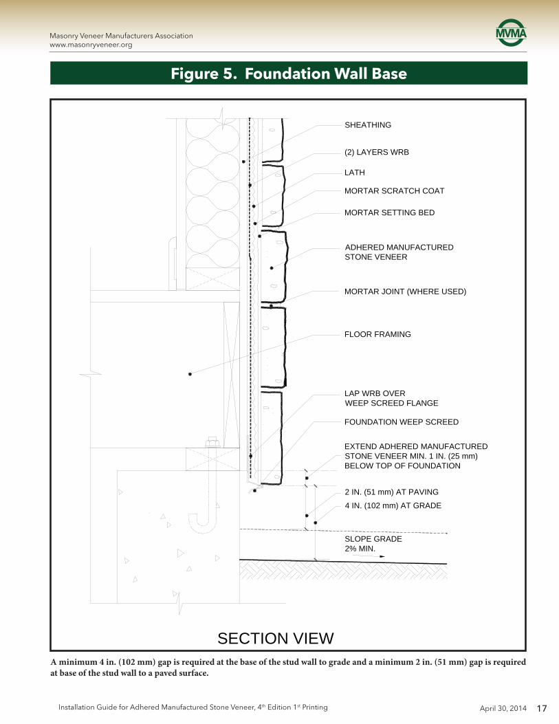
Figure 5. Foundation Wall Base
SHEATHING
(2) LAYERS WRB
LATH
MORTAR SCRATCH COAT
MORTAR SETTING BED
ADHERED MANUFACTURED STONE VENEER
MORTAR JOINT (WHERE USED)
FLOOR FRAMING
LAP WRB OVERWEEP SCREED FLANGE
FOUNDATION WEEP SCREED
EXTEND ADHERED MANUFACTURED STONE VENEER MIN. 1 IN. (25 mm) BELOW TOP OF FOUNDATION
2 IN. (51 mm) AT PAVING
4 IN. (102 mm) AT GRADE
SLOPE GRADE2% MIN.
SECTION VIEWA minimum 4 in. (102 mm) gap is required at the base of the stud wall to grade and a minimum 2 in. (51 mm) gap is required at base of the stud wall to a paved surface.

18
Masonry Veneer Manufacturers Associationwww.masonryveneer.org
April 30, 2014 Installation Guide for Adhered Manufactured Stone Veneer, 4th Edition 1st Printing
Figure 6. Foundation Wall Base – AMSV Overlapping Foundation
AMSV may overlap foundation wall with careful installation of flashing and WRB. This installation may continue down foundation wall to grade clearance.
FLASHING 6 in. (152 mm)
CMU OR CONCRETE WALLWATERPROOFING (WHERE REQ'D)
(2) LAYERS WRBCONTINUED (WHERE REQ'D)
LAP WRB OVERWEEP SCREED FLANGE
FOUNDATION WEEP SCREED
FLA
SH
ING
6 in
. (15
2 m
m)
SECTION VIEW
SHEATHING
(2) LAYERS WRB
LATH
MORTAR SCRATCH COAT
MORTAR SETTING BED
ADHERED MANUFACTURED STONE VENEER
MORTAR JOINT (WHERE USED)
(2) LAYERS WRB

19
Masonry Veneer Manufacturers Associationwww.masonryveneer.org
April 30, 2014Installation Guide for Adhered Manufactured Stone Veneer, 4th Edition 1st Printing
Figure 7. Foundation Wall – Transition to AMSV Continuing Down Foundation
AMSV may continue down the foundation with the incorporation of a flashing transition with careful installation of WRB and flashing.
SHEATHING
(2) LAYERS WRB
LATH
MORTAR SCRATCH COAT
MORTAR SETTING BED
ADHERED MANUFACTURED STONE VENEER
MORTAR JOINT (WHERE USED)
LAP WRB OVER FLASHINGSILL SCREED FLANGE
WEEP SCREED, DRIP SCREED, ORCASING BEAD (OPTIONAL)
BEDDING SEAL UNDER FLASHING WITH DRIP EDGE
FLASHING TRANSITION EXTEND MIN. 1 IN. (25 mm) BELOW TOP OF FOUNDATIONLATH (WHERE REQ'D)
MORTAR SETTING BED OVERMORTAR SCRATCH COAT
CMU OR CONCRETE WALLWATERPROOFING (WHERE REQ'D)
SECTION VIEW
1 IN
. (25
mm
)
20
Masonry Veneer Manufacturers Associationwww.masonryveneer.org
April 30, 2014 Installation Guide for Adhered Manufactured Stone Veneer, 4th Edition 1st Printing
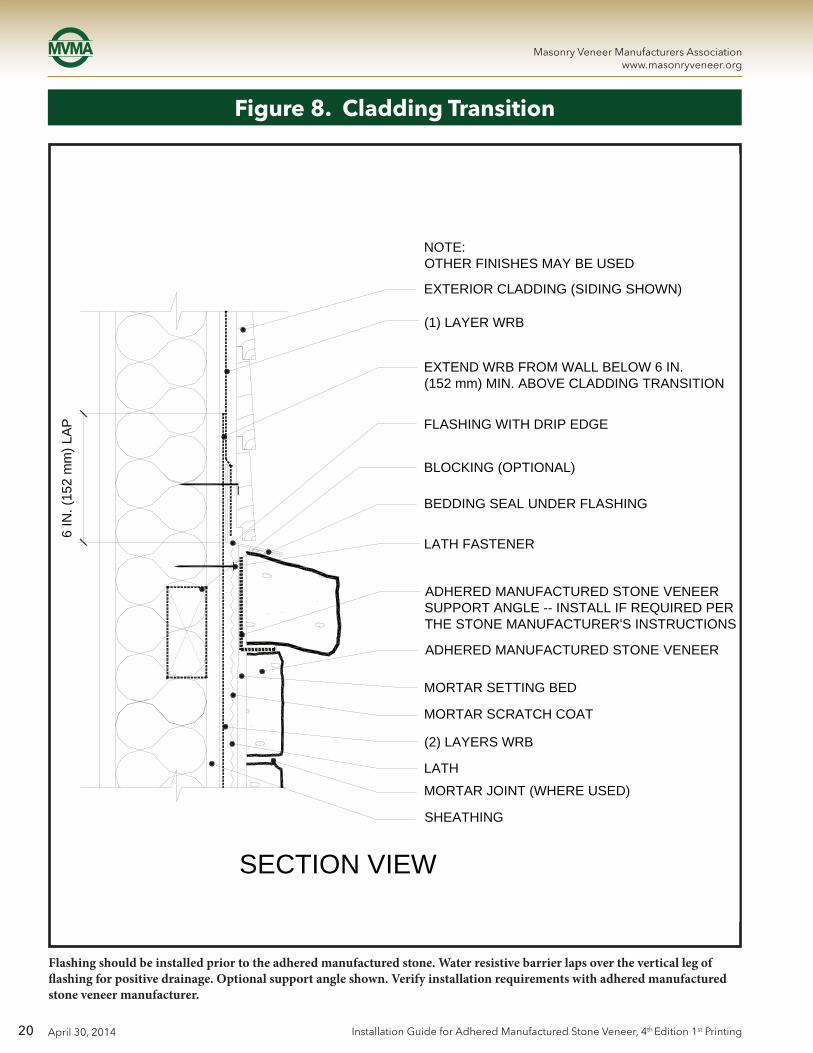
Flashing should be installed prior to the adhered manufactured stone. Water resistive barrier laps over the vertical leg of flashing for positive drainage. Optional support angle shown. Verify installation requirements with adhered manufactured stone veneer manufacturer.
Figure 8. Cladding Transition
EXTERIOR CLADDING (SIDING SHOWN)
NOTE:OTHER FINISHES MAY BE USED
(1) LAYER WRB
EXTEND WRB FROM WALL BELOW 6 IN. (152 mm) MIN. ABOVE CLADDING TRANSITION
FLASHING WITH DRIP EDGE
BLOCKING (OPTIONAL)
BEDDING SEAL UNDER FLASHING
LATH FASTENER
ADHERED MANUFACTURED STONE VENEERSUPPORT ANGLE -- INSTALL IF REQUIRED PER THE STONE MANUFACTURER'S INSTRUCTIONS
ADHERED MANUFACTURED STONE VENEER
MORTAR SETTING BED
MORTAR SCRATCH COAT
(2) LAYERS WRB
MORTAR JOINT (WHERE USED)
LATH
SHEATHING
SECTION VIEW
6 IN
. (15
2 m
m) L
AP

21
Masonry Veneer Manufacturers Associationwww.masonryveneer.org
April 30, 2014Installation Guide for Adhered Manufactured Stone Veneer, 4th Edition 1st Printing
Figure 9. Outside Corner
Randomly alternate short end returns above and below at the corner. Lap lath around the corner to the next framing member.
SHEATHING
BATT INSULATION
(2) LAYERS WRB
LATH -- WRAP LATH AROUNDCORNER TO NEXT FRAMINGMEMBER AND LAP AT FRAMING MEMBER
MORTAR SCRATCH COAT
MORTAR SETTING BED
ADHERED CONCRETE MASONRY VENEER
MORTAR JOINT (WHERE USED)
EXTEND AT LEAST ONE LAYER OF WRB FROM EACH DIRECTION AROUND CORNER 12 IN. (305 mm) MIN.
WALL SYSTEM AT CORNER
ADHERED CONCRETE MASONRY VENEER ALTERNATE SHORT END RETURNS ABOVE AND BELOW AT CORNER
PLAN VIEW

22
Masonry Veneer Manufacturers Associationwww.masonryveneer.org
April 30, 2014 Installation Guide for Adhered Manufactured Stone Veneer, 4th Edition 1st Printing
Figure 10. Inside Corner
Randomly alternate ends above and below to interweave the corner. Double wrap water resistive barrier around both sides of the corner. Lap lath to the framing at least 12 inches (305 mm) to the next framing member.
ADHERED MANUFACTURED STONE VENEERALTERNATE ENDS ABOVE AND BELOW TOINTERWEAVE CORNER
EXTEND AT LEAST ONE LAYER OF WRBFROM EACH DIRECTION AROUND CORNER 12 IN. (305 mm) MIN.
LATH - WRAP LATH AROUND CORNER TO NEXT FRAMING MEMBER AND LAP LATH AT FRAMING MEMBER
ADHERED MANUFACTURED STONE VENEER
MORTAR JOINT (WHERE USED)
MORTAR SCRATCH COAT
MORTAR SETTING BED
LATH
(2) LAYERS WRB
SHEATHING
PLAN VIEW

23
Masonry Veneer Manufacturers Associationwww.masonryveneer.org
April 30, 2014Installation Guide for Adhered Manufactured Stone Veneer, 4th Edition 1st Printing
Figure 11. Horizontal Transition
Note: flashing is lapped shingle-fashion with corrosion resistant sheet metal. A bedding seal is used under the corrosion resistant sheet metal next to the adhered manufactured stone veneer.
EXTERIOR SHEATHING (SIDING SHOWN)
NOTE: OTHER FINISHES MAY BE USED
(2) LAYERS WRB
FLASHING - PROVIDE END DAM AT FLASHING TERMINATION
HORIZONTAL WOOD TRIM (PRIMED)
STRIP OF FLASHING - LAP OVERFLASHING BELOW
BLOCKING FOR LATH EDGEAND FLASHING
FLASHING - PROVIDE END DAM ATFLASHING TERMINATION
BEDDING SEAL UNDER FLASHING
CASING BEAD (OPTIONAL) OVER WRB
ADHERED MANUFACTURED STONE VENEER
MORTAR SETTING BEDMORTAR SCRATCH COAT
LATH(2) LAYERS WRB
MORTAR JOINT (WHERE USED)
SHEATHING
EX
TEN
D W
RB
6 IN
. (15
2 m
m)
AB
OV
E F
LAS
HIN
G
SECTION VIEW

24
Masonry Veneer Manufacturers Associationwww.masonryveneer.org
April 30, 2014 Installation Guide for Adhered Manufactured Stone Veneer, 4th Edition 1st Printing
Figure 12. Vertical Transition
Flashing extends under the adjacent finishes. A 3/8 in. (10 mm) minimum gap should be used between finishes.
BLOCKING AT LATH EDGEFLASHING BEHIND TRIM - EXTEND UNDER ADJACENT FINISH AS REQUIREDADJACENT FINISHVARIES
BACKER ROD AND SEALANT
CASING BEAD AT SEALANT JOINT (OPTIONAL)
FLASHING
(2) LAYERS WRB - (1) LAYER UNDER FLASHING LAP (1) LAYER OVER FLASHING AND CASING BEAD
SHEATHING
WOOD TRIM (PRIMED) SIZE AND PROFILE MAY VARY
38 IN. (10 mm)
JOINTLAP FLASHING
OVER CASHING BEAD6 IN. (152 mm) MIN.
PLAN VIEW
LATHMORTAR SCRATCH COAT
MORTAR SETTING BED
ADHERED MANUFACTURED STONE VENEER
MORTAR JOINT(WHERE USED)

25
Masonry Veneer Manufacturers Associationwww.masonryveneer.org
April 30, 2014Installation Guide for Adhered Manufactured Stone Veneer, 4th Edition 1st Printing
ADHERED MANUFACTURED STONE VENEER
MORTAR SETTING BED
MORTAR SCRATCH COAT
MORTAR JOINT (WHERE USED)
LATH
(2) LAYERS WRB
SHEATHING
6 IN
. (15
2 m
m) M
IN. L
AP
FLA
SH
ING
OV
ER
WR
B
Figure 13. Open Eave - Overhang
Water resistive barrier should be in place prior to soffit installation followed by adhered manufactured stone veneer.

26
Masonry Veneer Manufacturers Associationwww.masonryveneer.org
April 30, 2014 Installation Guide for Adhered Manufactured Stone Veneer, 4th Edition 1st Printing
Figure 14. Open Eave - Flush
Water resistive barrier should be in place prior to soffit installation followed by adhered manufactured stone veneer.
WRB OR FLASHING
USE WOOD STOP OR 1X FILLER BEHIND FASCIA OPTION: CASING BEAD OVER FLASHING
1 IN. (25 mm) MIN. LAP OVER TOP OF ADHERED MANUFACTURED STONE VENEER
ADHERED MANUFACTURED STONE VENEER
MORTAR SETTING BEDMORTAR SCRATCH COAT
MORTAR JOINT (WHERE USED)
LATH
(2) LAYERS WRB
SHEATHING
6 IN
. (15
2 m
m) M
IN. L
AP
FLA
SH
ING
OV
ER
WR
B
SECTION VIEW
27
Masonry Veneer Manufacturers Associationwww.masonryveneer.org
April 30, 2014Installation Guide for Adhered Manufactured Stone Veneer, 4th Edition 1st Printing
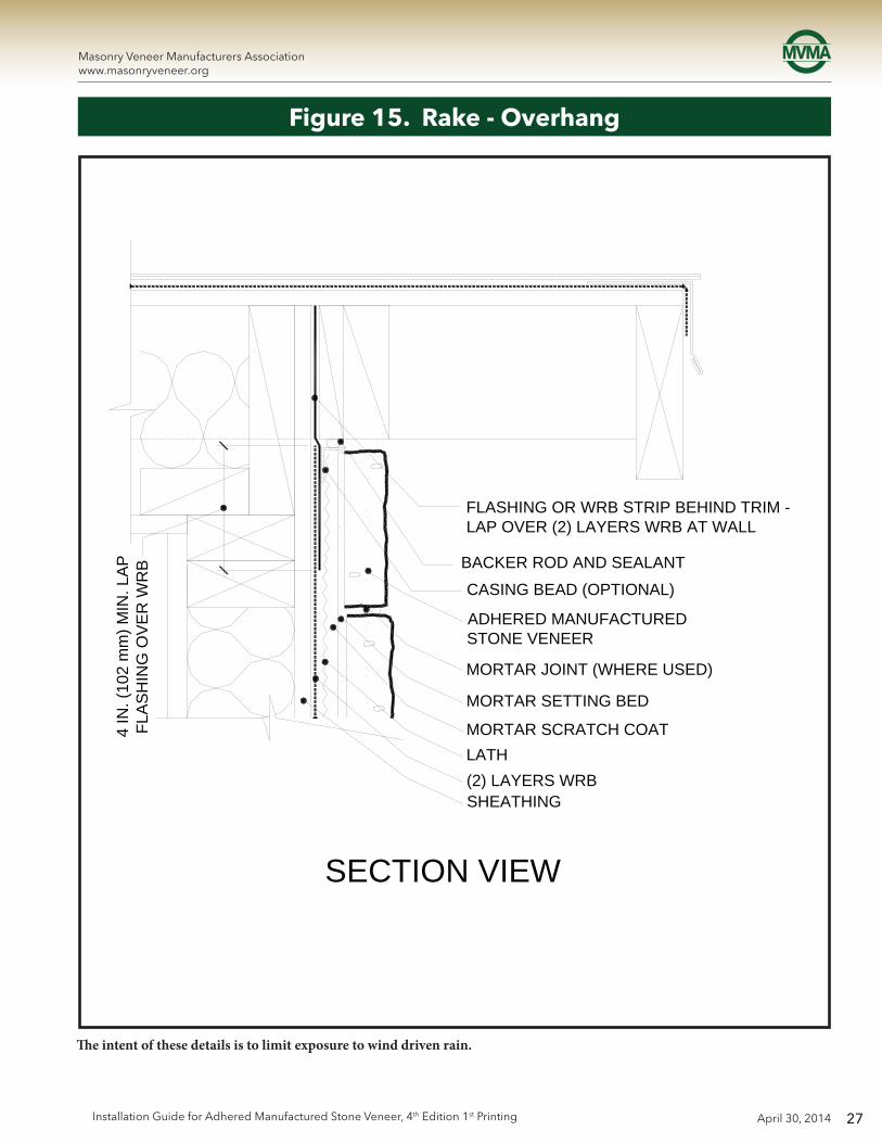
Figure 15. Rake - Overhang
The intent of these details is to limit exposure to wind driven rain.
FLASHING OR WRB STRIP BEHIND TRIM - LAP OVER (2) LAYERS WRB AT WALL
CASING BEAD (OPTIONAL)
ADHERED MANUFACTURED STONE VENEER
MORTAR JOINT (WHERE USED)
MORTAR SETTING BED
MORTAR SCRATCH COATLATH(2) LAYERS WRBSHEATHING
SECTION VIEW
4 IN
. (10
2 m
m) M
IN. L
AP
FLA
SH
ING
OV
ER
WR
B BACKER ROD AND SEALANT

28
Masonry Veneer Manufacturers Associationwww.masonryveneer.org
April 30, 2014 Installation Guide for Adhered Manufactured Stone Veneer, 4th Edition 1st Printing
Note: the use of backer rod and sealant.
Figure 16. Rake - Flush
FLASHING OR WRB STRIP BEHIND TRIM LAP OVER WRB AT WALL
1 IN. (25 mm) MIN. LAP OVER TOP OF ADHERED MANUFACTURED STONE VENEER
BACKER ROD AND SEALANT
CASING BEAD OVER (OPTIONAL)(2) LAYERS WRB - OPTION: USE WOOD STOP OR 1X FILLER BEHIND SUB-FASCIAADHERED MANUFACTURED STONE VENEER
MORTAR JOINT (WHERE USED)
MORTAR SETTING BED
MORTAR SCRATCH COAT
LATH(2) LAYERS WRB
SHEATHING
4 IN
. (10
2 m
m) M
IN. L
AP
FLA
SH
ING
OVE
R W
RB
SECTION VIEW

29
Masonry Veneer Manufacturers Associationwww.masonryveneer.org
April 30, 2014Installation Guide for Adhered Manufactured Stone Veneer, 4th Edition 1st Printing
Figure 17. Side Wall – Composition Shingles
Water resistive barrier laps over step flashing and weep screed.
ADHERED MANUFACTUREDSTONE VENEER
MORTAR SETTING BED
MORTAR SCRATCH COAT
MORTAR JOINT (WHERE USED)
LATH
BLOCKING FOR LATH EDGEAND FLASHING
(2) LAYERS WRB LAP OVER STEP FLASHING AND WEEP SCREED
STEP FLASHING AT RAKEPER ROOF MANUFACTURERE'S RECOMMENDATIONS
WEEP SCREED - LAPOVER STEP FLASHING 2 IN.(51 mm) MIN.
ROOF TYPE MAY VARY - COMPOSTION SHINGLEROOF SHOWN
ROOF UNDERLAYMENT -TURN UP AT SIDE WALL
2 IN
. (5
1mm
)M
IN.
SECTION VIEW

30
Masonry Veneer Manufacturers Associationwww.masonryveneer.org
April 30, 2014 Installation Guide for Adhered Manufactured Stone Veneer, 4th Edition 1st Printing
ADHERED MANUFACTUREDSTONE VENEER
(2) LAYERS WRBLAP OVER WEEP SCREEDAND COUNTERFLASHING
BLOCKING FOR LATH EDGE AND FLASHING
WEEP SCREED
COUNTERFLASHING
STEP FLASHING AT RAKE PERROOF MANUFACTURER'S RECOMMENDATION
ROOF TYPE MAY VARY -COMPOSTION SHINGLE ROOF SHOWN
ROOF UNDERLAYMENT -TURN UP AT SIDE WALL1X FILLER - SLOPE TOP
2 IN
. (51
mm
)M
IN.
2 IN
. (5
1 m
m)
MIN
.
2 IN
. (5
1 m
m)
MIN
.
Figure 18. Side Wall – Composition Shingles Curbing
This detail includes base trim. Note the counterflashing between trim and adhered manufactured stone veneer.

31
Masonry Veneer Manufacturers Associationwww.masonryveneer.org
April 30, 2014Installation Guide for Adhered Manufactured Stone Veneer, 4th Edition 1st Printing
ADHERED MANUFACTUREDSTONE VENEER
MORTAR SETTING BED
MORTAR SCRATCH COAT
LATH
BLOCKING FOR LATH EDGE AND FLASHING
(2) LAYERS WRB LAP OVER WEEP SCREED
WEEP SCREED OR DRIP SCREED LAP OVER RAKE WALL FLASHING2 IN. (51 mm) MIN.
SIDE WALL FLASHING PERROOF MANUFACTURER'SRECOMMENDATION
ROOF TYPE MAY VARY -TILE ROOF SHOWN
ROOF UNDERLAYMENT - TURN UP AT SIDE WALL
2 IN
. (5
1 m
m)
MIN
.
DETAIL VIEW
Figure 19. Side Wall – Tile Roofing
Water resistive barrier laps over step flashing and weep screed.

32
Masonry Veneer Manufacturers Associationwww.masonryveneer.org
April 30, 2014 Installation Guide for Adhered Manufactured Stone Veneer, 4th Edition 1st Printing
ADHERED MANUFACTURED STONE VENEER
(2) LAYERS WRB - LAPOVER WEEP SCREEDAND FLASHING
SCREED OR DRIP SCREED
BLOCKING FOR LATH EDGE AND FLASHING
COUNTERFLASHING
1X FILLER
SIDE WALL FLASHING PER ROOF MANUFACTURER'S RECOMMENDATION
ROOF TYPE MAY VARY - TILE ROOF SHOWN
ROOF UNDERLAYMENT - TURN UP AT SIDE WALL
DETAIL VIEW
2 IN
. (51
mm
) M
IN. L
AP
2 IN
. (5
1 m
m)
MIN
. Figure 20. Side Wall – Tile Roofing Curbing
This detail includes curbing. Note the counterflashing between trim and adhered manufactured stone veneer.

33
Masonry Veneer Manufacturers Associationwww.masonryveneer.org
April 30, 2014Installation Guide for Adhered Manufactured Stone Veneer, 4th Edition 1st Printing
WINDOW FRAMEPROFILE MAY VARY - REFER TO WINDOW MANUFACTURER'S DETAILS FOR INSTALLATION AND FLASHING
BEDDING SEALANT UNDER WINDOW FIN (IF REQUIRED PER WINDOW MANUFACTURER'S INSTRUCTIONS)
BACKER ROD AND SEALANT
CASING BEAD (OPTIONAL)
SILL FLASHING UNDER WINDOW FIN.LAP OVER WRB 4 IN. (102 mm) MIN.
38 IN. (10 mm)
ADHERED MANUFACTURED STONE VENEER WITH SLOPED TOPMORTAR SETTING BED
MORTAR JOINT (WHERE USED)
ADHERED MANUFACTURED STONE VENEER
MORTAR SCRATCH COAT
LATH
WRB UNDER SILL FLASHING
SHEATHING
DETAIL VIEW
AIR SEAL
Figure 21. Window Sill
Rough openings must be properly flashed prior to window installation. Tuck water resistive barrier under flashing at sill. Sill flashing should drain to the exterior of the primary WRB or to exterior of adhered manufactured stone veneer.

34
Masonry Veneer Manufacturers Associationwww.masonryveneer.org
April 30, 2014 Installation Guide for Adhered Manufactured Stone Veneer, 4th Edition 1st Printing
WINDOW FRAMEPROFILE MAY VARY - REFER TO WINDOW MANUFACTURER'S DETAILS FOR INSTALLATION AND FLASHING
JAMB FLASHING UNDERWINDOW FIN
BEDDING SEALANT UNDER WINDOW FIN
SHEATHING
(2) LAYERS WRBSEAL EDGE TO FIN
LATH
MORTAR SCRATCH COAT
MORTAR SETTING BED
MORTAR JOINT (WHERE USED)
ADHERED MANUFACTUREDSTONE VENEER
BEDDING SEALANT UNDER WRB LAPPED OVER CASING BEAD
CASING BEAD (OPTIONAL) LAP FLASHING OVER LEGBACKER ROD AND SEALANT
PLAN VIEW
38 IN.
(10 mm)
Figure 22. Window Jamb
Rough openings must be properly flashed prior to window installation. Backer rod and sealant between the window frame and the adhered manufactured stone veneer allows for movement between the dissimilar materials.

35
Masonry Veneer Manufacturers Associationwww.masonryveneer.org
April 30, 2014Installation Guide for Adhered Manufactured Stone Veneer, 4th Edition 1st Printing
SHEATHING
(2) LAYERS WRB
LATH
MORTAR SCRATCH COATMORTAR SETTING BED
ADHERED MANUFACTURED STONE VENEERMORTAR JOINT (WHERE USED)
ADHERED MANUFACTURED STONE VENEER KEY OR TRIM (WHERE OCCURS)
LAP WRB OVER HEAD FLASHINGAND SEAL EDGE
DRIP SCREED OR CASING BEAD (OPTIONAL)
HEAD FLASHING SET IN SEALANT(WIDTH TO COVER JAMB TREATMENT)
OPTIONAL BACKER ROD AND SEALANT
BEDDING SEALANT UNDER WINDOW FIN
WINDOW FRAME PROFILE MAY VARY - REFER TO WINDOW MANUFACTURER'S DETAILS FOR INSTALLATION AND FLASHING
38 IN. (10 mm)9
IN. (
229
mm
) MIN
. FLA
SH
ING
OV
ER
HE
AD
FIN
DETAIL VIEW
Figure 23. Window Head
Flashing and WRB installed shingle fashion may be complimented with self-adhered flashing to seal WRB to window frame.

36
Masonry Veneer Manufacturers Associationwww.masonryveneer.org
April 30, 2014 Installation Guide for Adhered Manufactured Stone Veneer, 4th Edition 1st Printing
Figure 24. Kick-Out Flashing
Kickout flashing should be sized properly to accommodate thickness of AMSV. Integration of WRB, flashing and kick-out critical.
ADHERED MANUFACTURED STONE VENEER
ROOFING MATERIAL
(2) LAYERS WRBLAP OVER SCREED ANDSTEP FLASHING
WEEP SCREED
STEP FLASHING AT ROOFING LAP OVER KICK-OUT FLASHING
KICK-OUT FLASHING - SEAL OVER EAVE FLASHING
SHINGLE LAP ALL WALL FLASHING PIECES WITH WRB
UNDERLAYMENT PER ROOF MANUFACTURER
EAVE DRIP EDGE FLASHING
GUTTER
WRB STRIP BEHIND TRIM LAP OVER WRB AT WALL
ISOMETRIC VIEW
37
Masonry Veneer Manufacturers Associationwww.masonryveneer.org
April 30, 2014Installation Guide for Adhered Manufactured Stone Veneer, 4th Edition 1st Printing
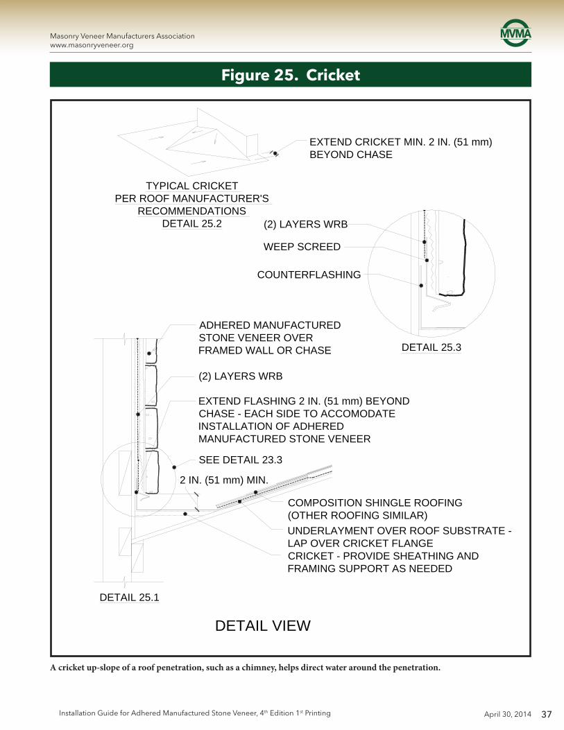
Figure 25. Cricket
TYPICAL CRICKET PER ROOF MANUFACTURER'S
RECOMMENDATIONS DETAIL 25.2
EXTEND CRICKET MIN. 2 IN. (51 mm) BEYOND CHASE
(2) LAYERS WRB
WEEP SCREED
COUNTERFLASHING
ADHERED MANUFACTURED STONE VENEER OVER FRAMED WALL OR CHASE DETAIL 25.3
(2) LAYERS WRB
EXTEND FLASHING 2 IN. (51 mm) BEYOND CHASE - EACH SIDE TO ACCOMODATE INSTALLATION OF ADHERED MANUFACTURED STONE VENEER
SEE DETAIL 23.3
COMPOSITION SHINGLE ROOFING (OTHER ROOFING SIMILAR)UNDERLAYMENT OVER ROOF SUBSTRATE - LAP OVER CRICKET FLANGECRICKET - PROVIDE SHEATHING AND FRAMING SUPPORT AS NEEDED
DETAIL 25.1
DETAIL VIEW
2 IN. (51 mm) MIN.
A cricket up-slope of a roof penetration, such as a chimney, helps direct water around the penetration.
38
Masonry Veneer Manufacturers Associationwww.masonryveneer.org
April 30, 2014 Installation Guide for Adhered Manufactured Stone Veneer, 4th Edition 1st Printing
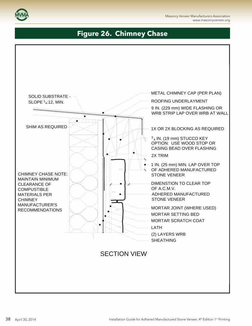
CHIMNEY CHASE NOTE:MAINTAIN MINIMUM CLEARANCE OF COMPUSTIBLE MATERIALS PER CHIMNEY MANUFACTURER'S RECOMMENDATIONS
SHIM AS REQUIRED
SOLID SUBSTRATE - SLOPE 14:12, MIN.
SECTION VIEW
METAL CHIMNEY CAP (PER PLAN)
ROOFING UNDERLAYMENT9 IN. (229 mm) WIDE FLASHING OR WRB STRIP LAP OVER WRB AT WALL
1X OR 2X BLOCKING AS REQUIRED
34 IN. (19 mm) STUCCO KEY
OPTION: USE WOOD STOP OR CASING BEAD OVER FLASHING
2X TRIM
1 IN. (25 mm) MIN. LAP OVER TOP OF ADHERED MANUFACTURED STONE VENEER
DIMENSTION TO CLEAR TOP OF A.C.M.V.ADHERED MANUFACTURED STONE VENEER
MORTAR JOINT (WHERE USED)MORTAR SETTING BEDMORTAR SCRATCH COATLATH(2) LAYERS WRBSHEATHING
Figure 26. Chimney Chase
39
Masonry Veneer Manufacturers Associationwww.masonryveneer.org
April 30, 2014Installation Guide for Adhered Manufactured Stone Veneer, 4th Edition 1st Printing
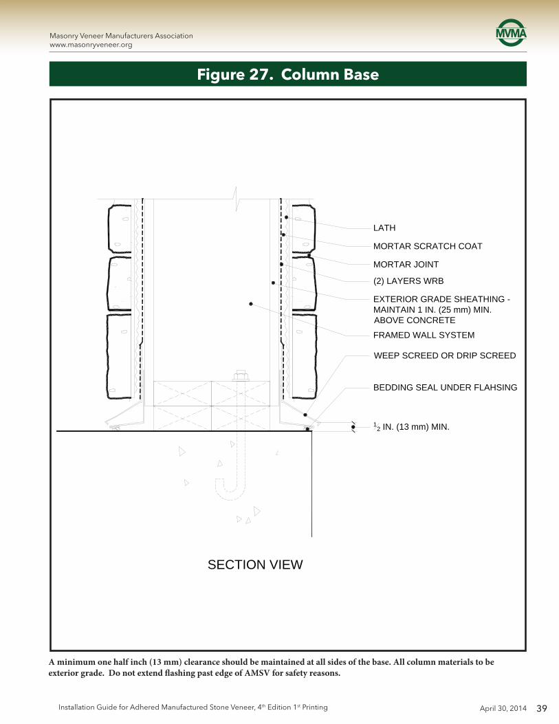
Figure 27. Column Base
A minimum one half inch (13 mm) clearance should be maintained at all sides of the base. All column materials to be exterior grade. Do not extend flashing past edge of AMSV for safety reasons.
SECTION VIEW
LATH
MORTAR SCRATCH COAT
MORTAR JOINT
(2) LAYERS WRB
EXTERIOR GRADE SHEATHING - MAINTAIN 1 IN. (25 mm) MIN. ABOVE CONCRETE
FRAMED WALL SYSTEM
WEEP SCREED OR DRIP SCREED
BEDDING SEAL UNDER FLAHSING
12 IN. (13 mm) MIN.

40
Masonry Veneer Manufacturers Associationwww.masonryveneer.org
April 30, 2014 Installation Guide for Adhered Manufactured Stone Veneer, 4th Edition 1st Printing
Figure 28. Raised Column Base
Adhered manufactured stone veneer may overlap the raised concrete pad, but a clearance of one half inch (13 mm) should be maintained at all sides of the base. Do not extend flashing past edge of AMSV.
DETAIL VIEW
RAISED CONCRETE PAD
FRAMED WALL SYSTEM
WEEP SCREED OR DRIP SCREED
BEDDING SEAL UNDER FLAHSING
12 IN. (13 mm) MIN.
LATH
MORTAR SCRATCH COAT
EXTERIOR GRADE SHEATHING - MAINTAIN 2 IN. (51 mm) MIN. ABOVE CONCRETE

41
Masonry Veneer Manufacturers Associationwww.masonryveneer.org
April 30, 2014Installation Guide for Adhered Manufactured Stone Veneer, 4th Edition 1st Printing
Figure 29. Penetration, Flanged
Penetration with flanges can be incorporated into the wall system by applying WRB in a watershed fashion and sealing cuts in the WRB with self-adhered flashing. Drawing illustrates installation with housewrap WRB. Installation with building paper WRB would be similar but instead of 45 degree cuts, fit last piece of WRB on top of flanges and tuck under WRB course above penetration (similar to Step 2 in Fig. 31.).
CUT WRB DIAGONALLY FROM TOP CORNERS PENETRATION FLANGE
(1) LAYER WRB
APPLY (1) LAYER SELF-ADHERED FLASHING (SAF) OVER WRB UNDER PENETRATION FLANGE
SEAL DIAGONAL CUTS IN WRB WITH (1) LAYER SAF
SEAL TOP FLAP OF WRB APPLY (1) LAYER SAF OVER TOP FLAP
APPLY (1) LAYER SAF OVER WRB EACH SIDE AND UNDER TOP FLAP OF CUT WRB
NOTE:2ND LAYER OF WRB (OUTER LAYER)TO BE APPLIED OVER FLANGE AND FLASHING OF PENETRATION
STEP 1
STEP 2
ISOMETRIC VIEW
42
Masonry Veneer Manufacturers Associationwww.masonryveneer.org
April 30, 2014 Installation Guide for Adhered Manufactured Stone Veneer, 4th Edition 1st Printing
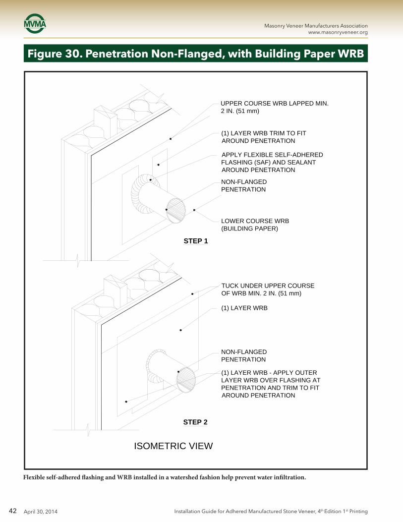
Figure 30. Penetration Non-Flanged, with Building Paper WRB
Flexible self-adhered flashing and WRB installed in a watershed fashion help prevent water infiltration.
UPPER COURSE WRB LAPPED MIN. 2 IN. (51 mm)
(1) LAYER WRB TRIM TO FIT AROUND PENETRATION
APPLY FLEXIBLE SELF-ADHERED FLASHING (SAF) AND SEALANT AROUND PENETRATION
STEP 1
STEP 2
ISOMETRIC VIEW
NON-FLANGED PENETRATION
LOWER COURSE WRB (BUILDING PAPER)
TUCK UNDER UPPER COURSE OF WRB MIN. 2 IN. (51 mm)
(1) LAYER WRB
NON-FLANGED PENETRATION
(1) LAYER WRB - APPLY OUTER LAYER WRB OVER FLASHING AT PENETRATION AND TRIM TO FIT AROUND PENETRATION
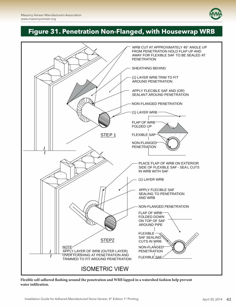
43
Masonry Veneer Manufacturers Associationwww.masonryveneer.org
April 30, 2014Installation Guide for Adhered Manufactured Stone Veneer, 4th Edition 1st Printing
Figure 31. Penetration Non-Flanged, with Housewrap WRB
Flexible self-adhered flashing around the penetration and WRB lapped in a watershed fashion help prevent water infiltration.
WRB CUT AT APPROXIMATELY 45° ANGLE UPFROM PENETRATION HOLD FLAP UP ANDAWAY FOR FLEXIBLE SAF TO BE SEALED ATPENETRATION
SHEATHING BEHIND
(1) LAYER WRB TRIM TO FITAROUND PENETRATION
APPLY FLECIBLE SAF AND (OR)SEALANT AROUND PENETRATION
NON-FLANGED PENETRATION
(1) LAYER WRB
FLAP OF WRBFOLDED UP
FLEXIBLE SAF
NON-FLANGEDPENETRATION
STEP 1
STEP2
PLACE FLAP OF WRB ON EXTERIORSIDE OF FLEXIBLE SAF - SEA L CUTSIN WRB WITH SAF
(1) LAYER WRB
APPLY FLECIBLE SAFSEALING TO PENETRATIONAND WRB
NON-FLANGED PENETRATION
FLAP OF WRBFOLDED DOWNON TOP OF SAFAROUND PIPE
FLEXIBLESAF SEALINGCUTS IN WRB
NON-FLANGEDPENETRATION
FLEXIBLE SAF
NOTE:APPLY LAYER OF WRB (OUTER LAYER)OVER FLASHING AT PENETRATION ANDTRIMMED TO FIT AROUND PENETRATION

44
Masonry Veneer Manufacturers Associationwww.masonryveneer.org
April 30, 2014 Installation Guide for Adhered Manufactured Stone Veneer, 4th Edition 1st Printing
INSULATIONWALL SYSTEMSHEATHING
(2) LAYERS WRB*
LATH
BED EXTERIOR FLANGE IN SEALANTPLASTER RING
MORTAR SETTING BED
ADHERED MANUFACTURED STONE VENEER
MORTAR SCRATCH COAT
(2) LAYERS WRB
MORTAR JOINT (WHERE USED)
LATH
INTERIOR EXTERIOR
SECTION VIEW*SEE FIGURES 29, 30, AND 31 FOR FLASHING OPTIONS.
Figure 32. Penetration, Fixture
Plaster rings should be affixed over the service box to bring the face of the box flush with the adhered manufactured stone veneer. Bed the exterior flange in sealant. Water resistive barrier should be installed snugly around the plaster ring flange.
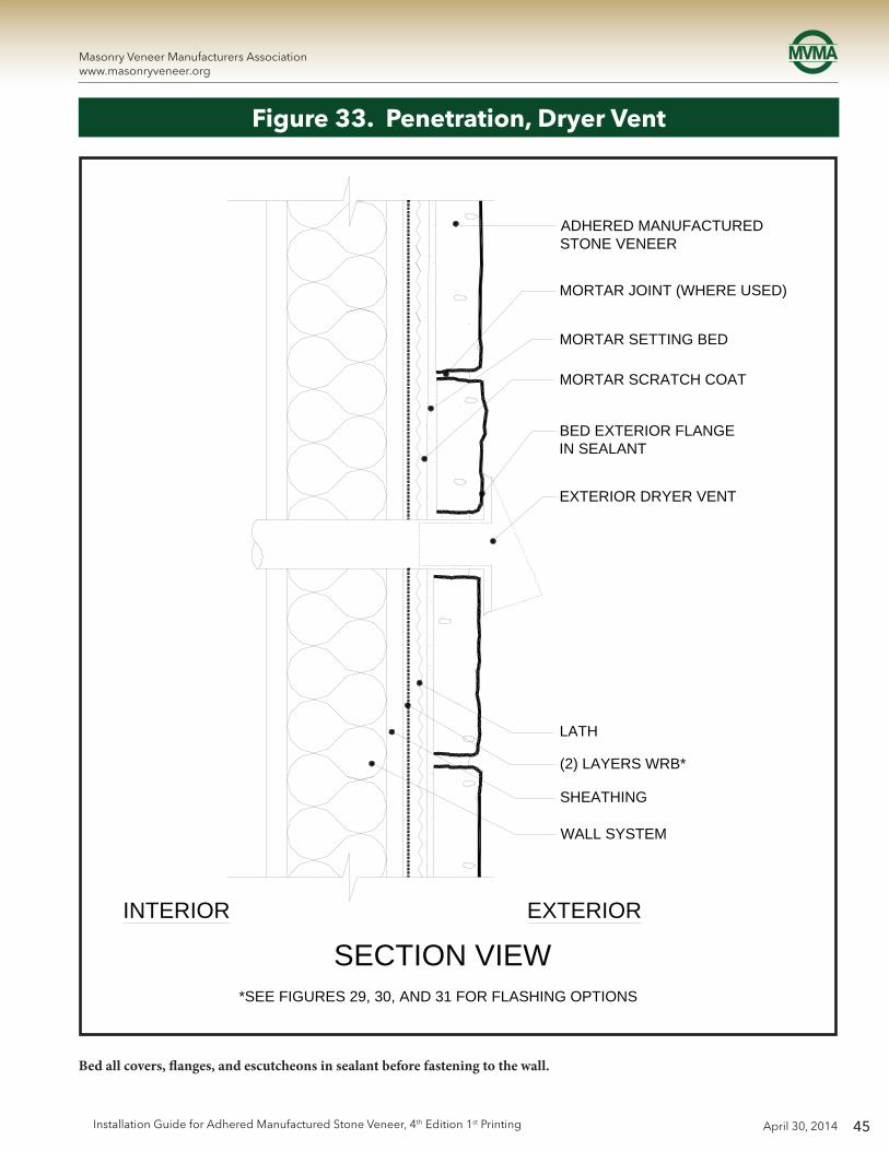
45
Masonry Veneer Manufacturers Associationwww.masonryveneer.org
April 30, 2014Installation Guide for Adhered Manufactured Stone Veneer, 4th Edition 1st Printing
Figure 33. Penetration, Dryer Vent
Bed all covers, flanges, and escutcheons in sealant before fastening to the wall.
INTERIOR EXTERIOR
SECTION VIEW
ADHERED MANUFACTURED STONE VENEER
MORTAR JOINT (WHERE USED)
MORTAR SETTING BED
MORTAR SCRATCH COAT
BED EXTERIOR FLANGEIN SEALANT
EXTERIOR DRYER VENT
LATH
(2) LAYERS WRB*
SHEATHING
WALL SYSTEM
*SEE FIGURES 29, 30, AND 31 FOR FLASHING OPTIONS

46
Masonry Veneer Manufacturers Associationwww.masonryveneer.org
April 30, 2014 Installation Guide for Adhered Manufactured Stone Veneer, 4th Edition 1st Printing
Figure 34. Deck Termination
Lap water resistive barrier over weep screed and floor framing to manage water intrusion. Provide gap between adhered manufactured stone veneer and decking for drainage. Water management at the deck ledger boards is critical, and may vary based on the building design.
SHEATHING
LATHMORTAR SCRATCH COAT
MORTAR SETTTING BED
ADHEREDMANUFACTURED STONE VENEER
MORTAR JOINT (WHERE USED)
(2) LAYERS WRB
LAP WRB OVER WEEP SCREED OR FLASHING
FLASHING OR WEEP SCREED
FLOOR FRAMING
LEDGER
DECK FRAMING
ADHERED MANUFACTUREDSTONE VENEER
FLASHING
MORTAR SETTING BED
MORTAR SSCRATCH COAT
(2) LAYERS WRB
LATH
SHEATHING
1 IN
. (25
mm
) M
IN.
SECTION VIEW

47
Masonry Veneer Manufacturers Associationwww.masonryveneer.org
April 30, 2014Installation Guide for Adhered Manufactured Stone Veneer, 4th Edition 1st Printing
A sloping solid shim should top the wall under the flashing and lath. Flashing should lap the top of the wall. Lath should lap over the top of the wall but be fastened only to vertical wall faces.
Figure 35. Wall Cap
ADHERED MANUFACTURED STONE VENEER CAP IN MORTAR SETTING BED
LEVEL SCRATCH COAT AT TOP OF WALL
LATH OVER TOP OF WALL - LAP OVER WALL LATH 4 IN. (102 mm) MIN. FASTEN LATH AT VERTICAL WALL FACES ONLY
FLASHING OVER TOP OF WALL CONSTRUCTION. LAP OVER WRB
SLOPING SOLID SHIM (e.g. BEVELED SIDING)
ADHERED MANUFACTURED STONE VENEER
MORTAR SETTING BED
MORTAR JOINT (WHERE REQUIRED)
MORTAR SCRATCH COAT
WRB (WHERE REQUIRED)
SHEATHINGWALL SYSTEM
WEEP SCREED OR DRIP SCREED
BEDDING SEAL UNDER FLASHING
2 IN
. (51
mm
) M
IN.
1 IN. (25 mm)
MIN.
SECTION VIEW

48
Masonry Veneer Manufacturers Associationwww.masonryveneer.org
April 30, 2014 Installation Guide for Adhered Manufactured Stone Veneer, 4th Edition 1st Printing
ADHERED MANUFACTURED STONE VENEERMORTAR SETTING BED
MORTAR SCRATCH COAT
LATH
(1) LAYER WRB OR MORTAR SCREENDRAINAGE MEDIUM
(1) LAYER WRB
SHEATHING
ISOMETRIC VIEW
Figure 36. Wall Assembly – Optional Rainscreen System – Drainage System
A rainscreen system incorporating a drainage medium (drainage mat or formed polymer sheeting, etc.) on the exterior side of the primary WRB.
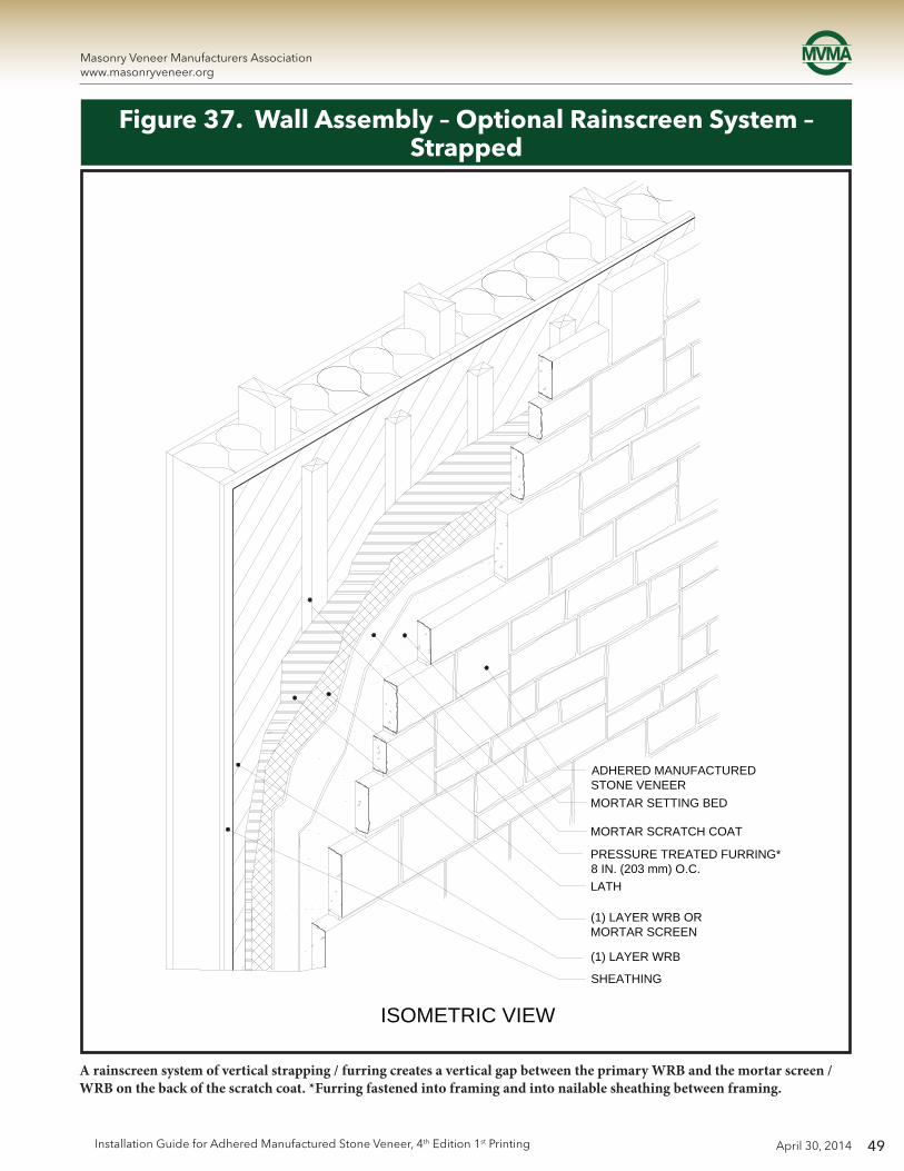
49
Masonry Veneer Manufacturers Associationwww.masonryveneer.org
April 30, 2014Installation Guide for Adhered Manufactured Stone Veneer, 4th Edition 1st Printing
A rainscreen system of vertical strapping / furring creates a vertical gap between the primary WRB and the mortar screen / WRB on the back of the scratch coat. *Furring fastened into framing and into nailable sheathing between framing.
ADHERED MANUFACTURED STONE VENEERMORTAR SETTING BED
MORTAR SCRATCH COAT
(1) LAYER WRB OR MORTAR SCREEN
(1) LAYER WRB
SHEATHING
ISOMETRIC VIEW
PRESSURE TREATED FURRING*8 IN. (203 mm) O.C.LATH
Figure 37. Wall Assembly – Optional Rainscreen System – Strapped

50
Masonry Veneer Manufacturers Associationwww.masonryveneer.org
April 30, 2014 Installation Guide for Adhered Manufactured Stone Veneer, 4th Edition 1st Printing
SHEATHING
WRB
DRAINAGE MEDIUM
MORTAR SCREEN / WRB
LATH
MORTAR SCRATCH COAT
MORTAR SETTING BED
ADHERED MANUFACTURED STONE VENEER
MORTAR JOINT (WHERE USED)
FLOOR FRAMING
LAP WRB OVER WEEP SCREED FLANGE
WEEP SCREED, DRIP SCREED, OR CASING BEAD (OPTIONAL)
FOUNDATION WEEP SCREED OR WEEP SCREED
EXTEND ADHERED MANUFACTURED STONE VENEER MIN. 1 IN. (25 mm) BELOW TOP OF FOUNDATION
2 IN. (51 mm) MIN. AT PAVING
4 IN. (102 mm) MIN. AT GRADE
SLOPE GRADE2% MIN.
SECTION VIEW
Figure 38. Foundation Wall Base – Optional Rainscreen System
The “Drainage Medium” of this wall section represents rainscreen products (such as drainage mats or formed polymer sheeting, etc.) or construction techniques (such as strapping or furring).

51
Masonry Veneer Manufacturers Associationwww.masonryveneer.org
April 30, 2014Installation Guide for Adhered Manufactured Stone Veneer, 4th Edition 1st Printing
Figure 39. Typical Wall Section – Optional Rainscreen System
The “Drainage Medium” of this wall section represents rainscreen products (such as drainage mats or formed polymer sheeting, etc.) or construction techniques (such as strapping or furring).
WALL SYSTEM
SHEATHING
(2) LAYERS WRB
LATH
MORTAR SCRATCH COAT
MORTAR SETTING BED
ADHERED MANUFACTUREDSTONE VENEER
MORTAR JOINT (WHERE USED)
EXTERIOR
SECTION VIEW

52
Masonry Veneer Manufacturers Associationwww.masonryveneer.org
April 30, 2014 Installation Guide for Adhered Manufactured Stone Veneer, 4th Edition 1st Printing
Figure 40. Retaining Wall (CMU)
Adhered masonry veneer offers attractive aesthetics to retaining walls.
2 IN. (51 mm) MIN. AT GRADE1
2 IN. (13 mm) MIN. AT PAVING
SECTION VIEW
APPLIED LIQUID WATERPROOF COATING
GRAVEL BACKFILL APPROXIMATELY 6 IN. (152 mm) WIDE PROVIDE DRAINAGE AT FOOTING
LANDSCAPE CLOTH (OPTIONAL)
ADHERED MANUFACTURED STONE VENEER CAP IN MORTAR SETTING BED
1 IN. (25 mm) MIN.
LEVEL SCRATCH COAT AT TOP OF WALL
ADHERED MANUFACTURED STONE VENEERMORTAR SETTING BED
MORTAR JOINT (WHERE USED)
CMU WALL SYSTEM WATERPROFFING (WHEN REQUIRED)
12 IN. (13 mm) MIN. AT PAVING
2 IN. (51 mm) MIN. AT GRADE
GRADE
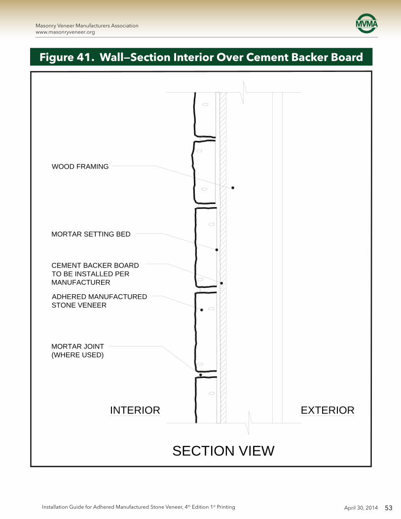
53
Masonry Veneer Manufacturers Associationwww.masonryveneer.org
April 30, 2014Installation Guide for Adhered Manufactured Stone Veneer, 4th Edition 1st Printing
Figure 41. Wall—Section Interior Over Cement Backer Board
WOOD FRAMING
MORTAR SETTING BED
CEMENT BACKER BOARD TO BE INSTALLED PER MANUFACTURER
ADHERED MANUFACTURED STONE VENEER
MORTAR JOINT(WHERE USED)
INTERIOR EXTERIOR
SECTION VIEW

54
Masonry Veneer Manufacturers Associationwww.masonryveneer.org
April 30, 2014 Installation Guide for Adhered Manufactured Stone Veneer, 4th Edition 1st Printing
Figure 42. Forward Mounted Commercial Window
(2) LAYERS WRB WRAPPED INTO ROUGH OPENING
SELF ADHERED FLASHING MEMBRANE
LATH
FIELD FAB CUSTOM DRIP CAP
(2) LAYERS WRB WRAPPED INTO ROUGH OPENING
CORNER UNIT
OPTIONAL CASING BEAD (NOT SHOWN)
BACKER ROD, SEALANT
WINDOW JAMB
BACKER ROD, SEALANT
OPTIONAL CASING BEAD(NOT SHOWN)PAN FLASHING
JAMB DETAIL
SECTION VIEW

55
Masonry Veneer Manufacturers Associationwww.masonryveneer.org
April 30, 2014Installation Guide for Adhered Manufactured Stone Veneer, 4th Edition 1st Printing
Figure 43. Forward Mounted Commercial Window—Top View
(2) LAYERS WRB WRAPPED INTO ROUGH OPENING
CORNER UNIT
BACKER ROD, SEALANT
WINDOW JAMB
OPTIONAL CASING BEAD(NOT SHOWN)
NOTE: FOR GUIDANCE WITH LATH FASTENING SYSTEM REFER TO THE FOAM COALITION WEBSITE, AS WELL AS LATH FASTENER SECTION OF THIS GUIDE. AIR BARRIER, VAPOR BARRIER, WATER-RESISTIVE BARRIER, WATERPROOFING MEMBRANE, FLASHING, LATH ATTACHMENT, Z-CHANNEL, AND INSULATION TYPE AND LOCATIONS TO BE DETERMINED BY DESIGN PROFESSIONAL
SECTION VIEW
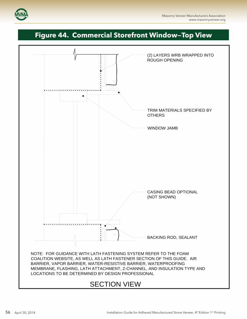
56
Masonry Veneer Manufacturers Associationwww.masonryveneer.org
April 30, 2014 Installation Guide for Adhered Manufactured Stone Veneer, 4th Edition 1st Printing
Figure 44. Commercial Storefront Window—Top View
WINDOW JAMB
(2) LAYERS WRB WRAPPED INTO ROUGH OPENING
TRIM MATERIALS SPECIFIED BY OTHERS
CASING BEAD OPTIONAL (NOT SHOWN)
BACKING ROD, SEALANT
SECTION VIEW
NOTE: FOR GUIDANCE WITH LATH FASTENING SYSTEM REFER TO THE FOAM COALITION WEBSITE, AS WELL AS LATH FASTENER SECTION OF THIS GUIDE. AIR BARRIER, VAPOR BARRIER, WATER-RESISTIVE BARRIER, WATERPROOFING MEMBRANE, FLASHING, LATH ATTACHMENT, Z-CHANNEL, AND INSULATION TYPE AND LOCATIONS TO BE DETERMINED BY DESIGN PROFESSIONAL

57
Masonry Veneer Manufacturers Associationwww.masonryveneer.org
April 30, 2014Installation Guide for Adhered Manufactured Stone Veneer, 4th Edition 1st Printing
Figure 45. Commercial Storefront Window
(2) LAYERS WRB WRAPPED INTO ROUGH OPENING
SELF ADHERED FLASHING MEMBRANE
(2) LAYERS WRB WRAPPED INTO ROUGH OPENINGOPTIONAL CASING BEAD (NOT SHOWN)
BACKER ROD, SEALANT
WINDOW JAMB
BACKER ROD, SEALANT
OPTIONAL CASING BEAD(NOT SHOWN)
PAN FLASHING
JAMB DETAIL
SECTION VIEW
TRIM MATERIALS SPECIFIED BY OTHERS
DRIP CAP
BEDDING SEAL
TRIM MATERIALS SPECIFIED BY OTHERS
SLOPPED SILL SPECIFIEDBY OTHERS

58
Masonry Veneer Manufacturers Associationwww.masonryveneer.org
April 30, 2014 Installation Guide for Adhered Manufactured Stone Veneer, 4th Edition 1st Printing
Figure 46. Wall—Section Multi-Floor Joint Detail
SECTION VIEW
NOTE: FOR GUIDANCE WITH LATH FASTENING SYSTEM REFER TO THE FOAM COALITION WEBSITE, AS WELL AS LATH FASTENER SECTION OF THIS GUIDE. AIR BARRIER, VAPOR BARRIER, WATER-RESISTIVE BARRIER, WATERPROOFING MEMBRANE, FLASHING, LATH ATTACHMENT, Z-CHANNEL, AND INSULATION TYPE AND LOCATIONS TO BE DETERMINED BY DESIGN PROFESSIONAL
LAP WRB OVER FLASHINGSILL SCREED FLANGE
WEEP SCREED, DRIP SCREED, OR WEEP CASING BEAD (OPTIONAL)
BEDDING SEAL UNDER
FLASHING WITH DRIP EDGE SIZED PER THICKEST STONE
FLASHING
SHEATHING
MORTAR SCRATCH COAT
MORTAR SETTING BED
ADHERED MANUFACTURED STONE VENEER
SEE DETAIL ABOVE
(2) LAYERS WRB
MORTAR JOINT (WHERE USED)
LATH
WALL SYSTEM
1 IN
. (25
mm
) MIN
.
DETAIL
WRB
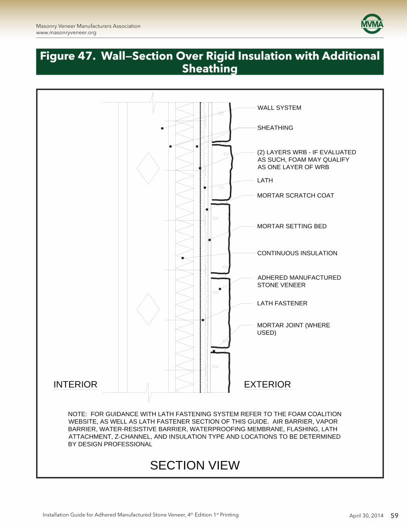
59
Masonry Veneer Manufacturers Associationwww.masonryveneer.org
April 30, 2014Installation Guide for Adhered Manufactured Stone Veneer, 4th Edition 1st Printing
Figure 47. Wall—Section Over Rigid Insulation with Additional Sheathing
SECTION VIEW
NOTE: FOR GUIDANCE WITH LATH FASTENING SYSTEM REFER TO THE FOAM COALITION WEBSITE, AS WELL AS LATH FASTENER SECTION OF THIS GUIDE. AIR BARRIER, VAPOR BARRIER, WATER-RESISTIVE BARRIER, WATERPROOFING MEMBRANE, FLASHING, LATH ATTACHMENT, Z-CHANNEL, AND INSULATION TYPE AND LOCATIONS TO BE DETERMINED BY DESIGN PROFESSIONAL
WALL SYSTEM
SHEATHING
(2) LAYERS WRB - IF EVALUATED AS SUCH, FOAM MAY QUALIFY AS ONE LAYER OF WRB
LATH
MORTAR SCRATCH COAT
MORTAR SETTING BED
CONTINUOUS INSULATION
ADHERED MANUFACTURED STONE VENEER
LATH FASTENER
MORTAR JOINT (WHERE USED)
EXTERIORINTERIOR

60
Masonry Veneer Manufacturers Associationwww.masonryveneer.org
April 30, 2014 Installation Guide for Adhered Manufactured Stone Veneer, 4th Edition 1st Printing
Figure 48. Wall—Section Over Continuous Rigid Insulation CMU
SECTION VIEW
NOTE: FOR GUIDANCE WITH LATH FASTENING SYSTEM REFER TO THE FOAM COALITION WEBSITE, AS WELL AS LATH FASTENER SECTION OF THIS GUIDE. AIR BARRIER, VAPOR BARRIER, WATER-RESISTIVE BARRIER, WATERPROOFING MEMBRANE, FLASHING, LATH ATTACHMENT, Z-CHANNEL, AND INSULATION TYPE AND LOCATIONS TO BE DETERMINED BY DESIGN PROFESSIONAL
LATH
EXTERIORINTERIOR
MASONRY WALL SYSTEM(CMU SHOWN)
MORTAR SCRATCH COAT
MORTAR SETTING BED
CONTINUOUS INSULATION
ADHERED MANUFACTURED STONE VENEER
LATH FASTENER EVERY 6 IN. (152 mm) AS PER SECTION 7.10.5 PER ASTM C1063
MORTAR JOINT (WHERE USED)
WRB (OPTIONAL)

61
Masonry Veneer Manufacturers Associationwww.masonryveneer.org
April 30, 2014Installation Guide for Adhered Manufactured Stone Veneer, 4th Edition 1st Printing
Figure 49. Wall-Section Inside Corner with Stucco—Top View
EXTEND AT LEAST ONE LAYER OF WRB FROM EACH DIRECTION AROUND CORNER 12 IN. (3O5 mm) MIN.
LATH - WRAP LATH AROUND CORNER TO NEXT FRAMING MEMBER
STUCCO
BACKER ROD AND SEALANT
ADHERED MANUFACTURED STONE VENEER
MORTAR JOINT (WHERE USED)
MORTAR SCRATCH COAT
MORTAR SETTING BED
LAP LATH AT FRAMING MEMBER
(2) LAYERS WRB
SHEATHING
PLAN VIEW

62
Masonry Veneer Manufacturers Associationwww.masonryveneer.org
April 30, 2014 Installation Guide for Adhered Manufactured Stone Veneer, 4th Edition 1st Printing
Figure 50. Wall-Section Insulated Concrete Form (ICF)—Top View
SECTION VIEW
NOTE: FOR GUIDANCE WITH LATH FASTENING SYSTEM REFER TO THE FOAM COALITION WEBSITE, AS WELL AS LATH FASTENER SECTION OF THIS GUIDE. AIR BARRIER, VAPOR BARRIER, WATER-RESISTIVE BARRIER, WATERPROOFING MEMBRANE, FLASHING, LATH ATTACHMENT, Z-CHANNEL, AND INSULATION TYPE AND LOCATIONS TO BE DETERMINED BY DESIGN PROFESSIONAL
ICF PLASTIC REINFORCEMENT TIES (TYPICAL)
ADHERED MANUFACTURED STONE VENEER
LATH FASTENER
MORTAR SETTING BED
WATERPROOFING MEMBRANE (OPTIONAL)
MORTAR SCRATCH COAT
(2) LAYERS WRB (IF NEEDED) IF EVALUATED AS SUCH, FOAM MAY QUALIFY AS ONE LAYER OF WRB
INSULATED CONCRETE FORM (BOTH SIDES)
CONCRETE CORE
LATH

63
Masonry Veneer Manufacturers Associationwww.masonryveneer.org
April 30, 2014Installation Guide for Adhered Manufactured Stone Veneer, 4th Edition 1st Printing
Figure 51. Wall-Section Over Continuous Rigid Insulation with Z Channels—Top View
SECTION VIEW
NOTE: FOR GUIDANCE WITH LATH FASTENING SYSTEM REFER TO THE FOAM COALITION WEBSITE, AS WELL AS LATH FASTENER SECTION OF THIS GUIDE. AIR BARRIER, VAPOR BARRIER, WATER-RESISTIVE BARRIER, WATERPROOFING MEMBRANE, FLASHING, LATH ATTACHMENT, Z-CHANNEL, AND INSULATION TYPE AND LOCATIONS TO BE DETERMINED BY DESIGN PROFESSIONAL
EXTERIORINTERIOR
WALL SYSTEM
(2) LAYERS WRB - IF EVALUATED AS SUCH, FOAM MAY QUALIFY AS ONE LAYER OF WRB
LATH
MORTAR SCRATCH COAT
MORTAR SETTING BED
CONTINUOUS INSULATION
ADHERED MANUFACTURED STONE VENEER
Z CHANNEL
MORTAR JOINT (WHERE USED)
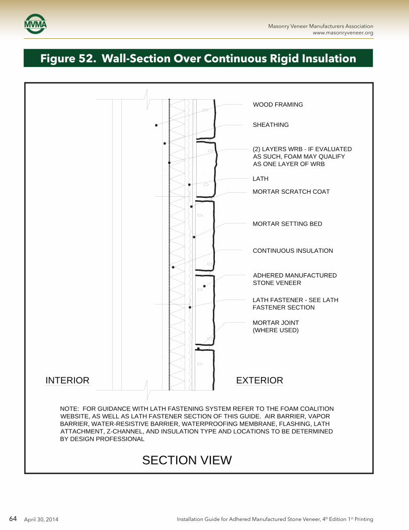
64
Masonry Veneer Manufacturers Associationwww.masonryveneer.org
April 30, 2014 Installation Guide for Adhered Manufactured Stone Veneer, 4th Edition 1st Printing
Figure 52. Wall-Section Over Continuous Rigid Insulation
SECTION VIEW
NOTE: FOR GUIDANCE WITH LATH FASTENING SYSTEM REFER TO THE FOAM COALITION WEBSITE, AS WELL AS LATH FASTENER SECTION OF THIS GUIDE. AIR BARRIER, VAPOR BARRIER, WATER-RESISTIVE BARRIER, WATERPROOFING MEMBRANE, FLASHING, LATH ATTACHMENT, Z-CHANNEL, AND INSULATION TYPE AND LOCATIONS TO BE DETERMINED BY DESIGN PROFESSIONAL
EXTERIORINTERIOR
(2) LAYERS WRB - IF EVALUATED AS SUCH, FOAM MAY QUALIFY AS ONE LAYER OF WRB
LATH
MORTAR SCRATCH COAT
MORTAR SETTING BED
CONTINUOUS INSULATION
ADHERED MANUFACTURED STONE VENEER
MORTAR JOINT (WHERE USED)
WOOD FRAMING
SHEATHING
LATH FASTENER - SEE LATH FASTENER SECTION

65
Masonry Veneer Manufacturers Associationwww.masonryveneer.org
April 30, 2014Installation Guide for Adhered Manufactured Stone Veneer, 4th Edition 1st Printing
Figure 53. Wall-Section Parapet with Stone Cap
SECTION VIEW
1X FILLER - SLOPE TOP
ROOF UNDERLAYMENT - TURN UP AT SIDE WALL
(2) LAYERS WRB
ADHERED MANUFACTURED STONE VENEER
MORTAR JOINT (WHERE USED)
MORTAR SETTING BED
CONTINUOUS INSULATION
LATH
SCRATCH COAT
BACKER ROD & SEALANT
SLOPING SOLID SHIM (e.g. BEVELED SIDING)
FLASHING OVER TOP OF WALL CONSTRUCTION. LAP OVER WRB
LEVEL SCRATCH COAT AT TOP OF WALL
LATH OVER TOP OF WALL - LAP OVER WALL LATH 4 IN. (102 mm) MIN. FASTEN LATH AT VERTICAL WALL FACES ONLY
ADHERED MANUFACTURED STONE VENEER CAP IN MORTAR SETTING BED
SHEATHING
SCUPPER
CURF
1IN. (25 mm) MIN.

66
Masonry Veneer Manufacturers Associationwww.masonryveneer.org
April 30, 2014 Installation Guide for Adhered Manufactured Stone Veneer, 4th Edition 1st Printing
Figure 54. Wall-Section Parapet with Steel Cap
LATH
SCRATCH COAT
SHEATHING
1 IN. (25 mm)
PE
R A
RC
H.
STY
LE
SECTION VIEW
(2) LAYERS WRB
PRESSURE TREATED BLOCKING
SLOPED METAL COPING SYSTEM
DRIP EDGE PERARCH.
MEMBRANE FLASHING EXTEND OVER TOP OF PARAPET
ADHERED MANUFACTURED STONE VENEER
SCUPPER
MORTAR JOINT (WHERE USED)
SEALANT, TYPICAL
ROOF SYSTEM PER ARCH.
MORTAR SETTING BED
CONTINUOUS INSULATION

67
Masonry Veneer Manufacturers Associationwww.masonryveneer.org
April 30, 2014Installation Guide for Adhered Manufactured Stone Veneer, 4th Edition 1st Printing
Notes:
