installation guide - big ass solutions · purlins, trusses, or bar joists. consult a structural...
TRANSCRIPT

INSTALLATION GUIDE
Powerfoil®8 Basic 6®
For help, call 1-877-BIG-FANS or visit www.bigassfans.com

PRE-INSTALLATION CHECKLISTI have the appropriate mount to accommodate the roof pitch and my building structure.
Big Ass Fans can only be mounted to I-beams or angle iron. Do not directly mount the fan to single purlins, trusses, or bar joists. Consult a structural engineer for mounting methods not covered in this manual.
A structural engineer approved the mounting structure.
The mounting structure must be able to withstand the torque forces generated by the fan. The largest Big Ass Fan generates up to 300 ft·lb (406.7 N·m) of torque during operation.
I am familiar with the function of the safety cable.
If my fan’s extension tube is 4 ft (1.2 m) or longer or if the fan is installed near any building fixtures, I will secure the fan with the provided guy wires as a safety measure.
The fan will be installed so that the airfoils are at least 10 ft (3.05 m) above the floor.
The fan will be installed so that the airfoils have a minimum of 2 ft (0.61 m) of clearance from obstructions and the building structure.
The distance of the fan from the ceiling should be measured from the top of the winglets to the ceiling.
The fan will be installed so that it is not subjected to high winds such as from an HVAC system or near a large garage door.
If the fan is mounted at the same level or higher than a diffuser, the winglets must be at a distance that is at least 1x the measure of the fan’s diameter. If the fan is mounted at the same height or below a diffuser, the winglets must be at a distance that is at least 2x the measure of the fan’s diameter.
The distance between multiple fans must be at least 2.5x the fans’ diameter when measured from the centers of the fans.
The upper mount is the correct size for the I-beam.
The airfoils and other fan components are those that were shipped with the motor unit. If installing multiple fans, do not mix and match fan components.
The supply power circuit is appropriate for the VFD, and power wiring is routed to the site of fan and the controller installation.
See the specification label on the fan for power requirements.

READ AND SAVE THESE INSTRUCTIONS
WARNING AND CAUTION SYMBOLIndicates a hazard with a medium level of risk that could result in injury or death or damage to property if not avoided.
ELECTRICAL WARNING SYMBOL Indicates an electrical hazard with a medium level of risk that could result in death or serious injury if not avoided.
This product was manufactured in a plant whose Management System is certified as being in conformity with ISO 9001.
LegalImproper installation, delivery, or maintenance, including, but not limited to, any of the following actions by the customer or agent of the customer will constitute a breach of and will void all warranties:
• Failure to follow the required installation procedures specified in this Installation Guide and in all other documentation supplied with the fans and related equipment including documentation provided by the manufacturers of the individual fan and control components;
• Failure to follow all relevant codes and ordinances, including, but not limited to, the National Electric Code (United States), applicable national and local electrical codes, and state and local building codes;
• Failure to follow electrical engineering industry standards regarding the approved method of installing solid-state electrical equipment having the characteristics of the fans, the fan controls, and their related components, even if such standards are not specifically referenced in any instructions or literature supplied by Big Ass Solutions or provided by manufacturers.
Basic 6 and Powerfoil are trademarks of Delta T Corporation. All other trademarks used herein are the properties of their respective owners. No part of this document may be reproduced or translated into a different language without the prior written consent of Big Ass Solutions. The information contained in this document is subject to change without notice. For the most up-to-date information, see the online installation guide at www.bigassfans.com
www.bigassfans.com/patents ▪ www.bigassfans.com/product-warranties
Conforms to ANSI/UL STD 507: Electric FansCertified to CAN/CSA C22.2 Fans & Ventilators
Installation GuideOctober 2017Rev. E10/03/2017
Original English Instructions

IMPORTANT SAFETY INSTRUCTIONS
WARNING—TO REDUCE THE RISK OF FIRE, ELECTRIC SHOCK, OR INJURY TO PERSONS, OBSERVE THE FOLLOWING:
WARNING: Installation work and electrical wiring must be done by qualified person(s) in accordance with all applicable codes and standards, including fire-rated construction.
WARNING: When cutting or drilling into a wall or ceiling, do not damage electrical wiring and other hidden utilities.
WARNING: The installation of all Big Ass Fan models covered under this manual must be installed in accordance with the requirements specified in this installation manual and with all national and local electrical codes. Code compliance is ultimately YOUR responsibility! Failure to comply with these codes could result in personal injury or property damage.
WARNING: Before servicing or cleaning the fan, switch power off at service panel and lock the service disconnecting means to prevent power from being switched on accidentally. When the service disconnecting means cannot be locked, securely fasten a prominent warning device, such as a tag, to the service panel.
WARNING: Big Ass Fans must be installed with part(s) that are marked (on their cartons) to Indicate the suitability with this model. Other similar part(s) cannot be substituted.
WARNING: This appliance is not intended for use by persons (including children) with reduced physical, sensory or mental capabilities, or lack of experience and knowledge, unless they have been given supervision or instruction concerning use of the appliance by a responsible person.
CAUTION: Exercise caution and common sense when powering the fan. Do not connect the fan to a damaged or hazardous power source. Do not attempt to resolve electrical malfunctions or failures on your own. Contact Big Ass Fans if you have any questions regarding the electrical installation of this fan.
CAUTION: Do not bend the airfoils when installing or servicing the fan. Do not insert foreign objects between rotating airfoils.
CAUTION: Use this fan only in the manner intended by Big Ass Fans. If you have questions, contact Customer Service.
CAUTION: Do not operate fan with damaged cord or plug. Return fan to authorized service facility for examination or repair.
ATTENTION: If installing the fan in the United States, the fan must be installed per the following National Fire Protection Association (NFPA) guidelines:
• The fan must be centered approximately between four adjacent sprinklers.• The vertical distance from the fan to the sprinkler deflector must be at least 3 ft (91.4 cm).• The fan must be interlocked to shut down immediately upon receiving a waterflow signal from the alarm
system.

CONTENTSIntroduction Important Safety Instructions ii
Technical Specifications 1
Pre-Installation Before Installing Your Fan 2Parts and Hardware 3Fan Diagram 4Where to Install Your Fan 5
Installation Overview 101a. Prepare the I-Beam 111b. Prepare the Angle Irons 122. Directly Mount Main Fan Unit to Angle Irons 153a. Attach Upper Mount to I-Beam 163b. Attach Upper Mount to Angle Irons 174. Attach the Extension Tube 185. Secure the Safety Cable 186. Attach Lower Yoke 197. Attach Main Fan Unit 198. Confirm Orientation 209. Install Guy Wires 2010. Mount the Variable Frequency Drive (VFD) 2311. Install the Electronic Programming Module (EPM) 2412. Wire the Fan and VFD 2413. Install the Airfoils 2514. Install the Hub Cover (Powerfoil 8/Powerfoil 8 Plus only) 26
Electrical Guidelines Cable Types 27Grounding 28Input Voltage Irregularities 28Delta Secondary 29Branch Circuit Protection 30VFD Wiring: ESFR (Early Suppression Fast Response) 31VFD Wiring: 100-125 V & 200-240 V, 1 Φ Controller 32VFD Wiring: 200–240 V, 3 Φ Controller 33VFD Wiring: 400-480 V & 575-600 V, 3 Φ Controller 34Daisy Chaining 35Motor Wiring: 9-Lead, Dual Voltage, Wye Motor Configuration 36
Operating the Controller
Starting and stopping the fan 37Adjusting fan speed 37Reversing direction of fan rotation 37
Operating the Fan Heating Season 38Cooling Season 38
Onboard VFD 1. Attach Mounting Brackets 392. Attach VFD 403. Attach Mounting Plate 404. Connect to VFD 40Operation 42

Maintenance Annual Preventative Maintenance 43General Preventative Maintenance 43Annual Maintenance Checklist 44
Troubleshooting General Troubleshooting 45Cutting the Extension Tube 46Status and warning messages 47Fault messages 48179 diagnostics running display options 49
Warranty Contact Us 51Check-In Procedure 53Close-Out Procedure 55

WWW.BIGASSSOLUTIONS.COM © 2016 DELTA T CORP. ALL RIGHTS RESERVED. 1
TECHNICAL SPECIFICATIONSNote: All controllers produce 3-phase output power regardless of input phase.
Basic 6Diameter Motor Size Minimum Circuit Size Full Load Amps (Fan)
8 ft (2.4 m)1.0 hp
(0.75 kW)
15 A @ 100–125 V, 1 Φ15 A @ 200–240 V, 1 Φ 10 A @ 200–240 V, 3 Φ 10 A @ 400–480 V, 3 Φ10 A @ 575–600 V, 3 Φ
9.0 A 8.8 A 5.0 A 2.6 A 1.3 A
10 ft (3.0 m)
12 ft (3.6 m)1.5 hp (1.1 kW)
25 A @ 200–240 V, 1 Φ 15 A @ 200–240 V, 3 Φ 10 A @ 400–480 V, 3 Φ10 A @ 575–600 V, 3 Φ
13.3 A 5.0 A 2.6 A 2.0 A14 ft (4.3 m)
16 ft (4.9 m)
2.0 hp (1.5 kW)
25 A @ 200–240 V, 1 Φ 15 A @ 200–240 V, 3 Φ 10 A @ 400–480 V, 3 Φ10 A @ 575–600 V, 3 Φ
13.3 A 8.1 A 4.8 A 2.7 A
18 ft (5.5 m)
20 ft (6.1 m)
24 ft (7.3 m)
Powerfoil 8 PlusFan Diameter Motor Size Minimum Circuit Size Full Load Amps (Fan)
PP82-10 12 ft (3.6 m)1.5 hp (1.1 kW)
25 A @ 200–240 V, 1 Φ 15 A @ 200–240 V, 3 Φ 10 A @ 400–480 V, 3 Φ10 A @ 575–600 V, 3 Φ
8.8–7.2 A 5.0–4.2 A 2.6–2.0 A 2.0–1.6 A
PP82-12 14 ft (4.3 m)1.5 hp (1.1 kW)
25 A @ 200–240 V, 1 Φ 15 A @ 200–240 V, 3 Φ 10 A @ 400–480 V, 3 Φ10 A @ 575–600 V, 3 Φ
12.4–11.1 A5.0–4.2 A3.5–3.2 A2.0–1.6 A
PP82-14 16 ft (4.9 m)2.0 hp
(1.5 kW)
25 A @ 200–240 V, 1 Φ 15 A @ 200–240 V, 3 Φ 10 A @ 400–480 V, 3 Φ10 A @ 575–600 V, 3 Φ
12.4–11.1 A7.2–5.5 A3.5–3.2 A2.7–2.2 A
PP82-16 18 ft (5.5 m)
2.0 hp (1.5 kW)
25 A @ 200–240 V, 1 Φ 15 A @ 200–240 V, 3 Φ 10 A @ 400–480 V, 3 Φ10 A @ 575–600 V, 3 Φ
15.8–14.0 A 7.2–5.5 A 4.4–4.0 A 2.7–2.2 A
PP82-18 20 ft (6.1 m)
PP82-20 22 ft (6.7 m)
PP82-24 24 ft (7.3 m)
Powerfoil 8Fan Diameter Motor Size Minimum Circuit Size Full Load Amps (Fan)
PF82-08 8 ft (2.4 m)1.0 hp
(0.75 kW)
15 A @ 100–125 V, 1 Φ15 A @ 200–240 V, 1 Φ 10 A @ 200–240 V, 3 Φ 10 A @ 400–480 V, 3 Φ10 A @ 575–600 V, 3 Φ
9.0–7.2 A 8.7–7.6 A 5.0–3.8 A 2.4–2.1 A 1.3–1.0 A
PF82-10 10 ft (3.0 m)
PF82-12 12 ft (3.6 m)1.5 hp (1.1 kW)
25 A @ 200–240 V, 1 Φ 15 A @ 200–240 V, 3 Φ 10 A @ 400–480 V, 3 Φ10 A @ 575–600 V, 3 Φ
12.4–11.1 A 5.0–4.3 A 3.5–3.2 A 2.0–1.6 APF82-14 14 ft (4.3 m)
PF82-16 16 ft (4.9 m)
2.0 hp (1.5 kW)
25 A @ 200–240 V, 1 Φ 15 A @ 200–240 V, 3 Φ 10 A @ 400–480 V, 3 Φ10 A @ 575–600 V, 3 Φ
15.8–14.0 A 8.1–4.8 A 4.4–4.0 A 2.7–2.2 A
PF82-18 18 ft (5.5 m)
PF82-20 20 ft (6.1 m)
PF82-24 24 ft (7.3 m)

WWW.BIGASSSOLUTIONS.COM © 2016 DELTA T CORP. ALL RIGHTS RESERVED.2
BEFORE INSTALLING YOUR FANReview the following pre-installation procedures and checks to ensure you have all necessary items for installation.
ToolsThe largest Big Ass Fan weighs a maximum of 415 lbs (188 kg). A suitable means for lifting the weight of the fan, such as a scissor lift, at least two personnel, and the following tools will be required. Note: Depending on your application, additional tools may be required.
☐ Standard wrench set
☐ Standard socket set and ratchet
☐ Torque wrench capable of 40 ft·lb (54.2 N·m) & 3/4” socket
☐ Phillips and flat head screwdrivers
☐ Standard allen wrench set
☐ 1/4” nut driver
☐ 5/16” nut driver
☐ #10 to #14 AWG strippers
☐ Medium channel locks
☐ Multimeter
Power supply guidelinesIf you are unfamiliar or uncomfortable with the installation of electrical components, do not attempt to install the fan without an electrician. This guide is merely a recommendation of proper installation.
✓ Dedicated Branch Circuit Protection. Each fan requires dedicated branch circuit protection.
✓ Circuit Requirements. Refer to the fan label for appropriate circuit requirements for your fan size.
✓ Conduit. Controller output/motor input leads cannot share a conduit with any other controller’s AC supply feed.
✓ Local Disconnect. If required, a local disconnect should be installed per NEC and all local codes.
✓ Onboard VFD. If you are installing an onboard variable frequency drive (VFD), route the power wiring to the location where the fan will be mounted.
✓ Manual Disconnect. To satisfy some local code requirements, it may be necessary to install a manual disconnect at the fan motor location when the fan assembly is not within “line-of-sight” from the VFD. A non-fused, 600 V, 3-phase, blade style disconnect should be used to satisfy this “line-of-sight” requirement.
Power wiring guidelines ✓ To reduce the risk of electric shock, wiring should be performed by a qualified electrician. Incorrect assembly
can cause electric shock or damage to the motor or controller.
✓ The electrical installation of the fan must be in accordance with the National Electrical Code, ANSI/NFPA 70-2014, if applicable, and all local codes.
✓ See the Electrical Guidelines section for complete input power guidelines.

WWW.BIGASSSOLUTIONS.COM © 2016 DELTA T CORP. ALL RIGHTS RESERVED. 3
HardwareFan hardware for hanging the fan and airfoils is provided on hardware boards. Verify you have all of the following required hardware before beginning the installation process.
Mounting Hardware Board1
Upper Mount Hardware• (4) 1/2-13 x 2” Bolts• (8) 1/2” Flat Washers• (4) 1/2-13 Nylock Nuts
Safety Cable Shackle
Extension Tube Hardware• (2) 1/2-13 x 4-1/2” Bolts• (4) 1/2” Flat Washers• (2) 1/2-13 Nylock Nuts
Lower Yoke Hardware• (2) 1/2-13 x 4-1/2” Bolts• (4) 1/2” Flat Washers• (2) 1/2-13 Nylock Nuts
Motor Unit Hardware• (4) 1/2-13 x 1-3/4” Bolt• (8) 1/2” Flat Washer• (4) 1/2-13 Nylock Nut
Airfoil and Winglet Hardware BoardsAirfoil Hardware• 5/16-18 x 2’’ GR 8 Bolt• 5/16” Flat Washer• 5/16-18 Nylock Nut
Winglet Hardware• 10-24 x 3/4” Barrel• 10-24 x 1/2” Bolt
Guy Wire Hardware2
• Locking Carabiners• 1/4” Beam Clips• 1/4-20 x 1” Eyebolts• 1/4-20 Hex Nuts
• Gripples• Guy Wires• Wire Rope Clips
1. Square washers are included and are only used if you are mounting the fan to angle irons. The number of square washers used depends on the number of angle irons used.2. Guy wires and hardware are only included with your order if the fan’s lateral movement needs to be restrained. Big Ass Fans recommends using guy wires if the extension tube
is four feet or longer, or if the fan is exposed to high winds or similar conditions, or if the fan is near building structural components.
PartsCheck that the fan boxes have all the parts before beginning installation. If you ordered multiple fans, be sure to keep the components of each fan together. The fans each have differently rated components that are not interchangeable. Note: Illustrations are not to scale.
(2) Beam Clip (2) Spacer
Upper Mount1 Lower Yoke Hub Cover2 EPM Module & Fire Relay3
OR
Airfoils4 Winglets5 Airfoil Retainers Wall Controller
Main Fan Unit
1. The upper mount may differ from the picture. Confirm that you have the appropriate mount for your roof pitch.
2. Powerfoil 8 and Powerfoil 8 Plus only.3. The fire relay is not shown. If multiple fans are to be installed, make sure to install the exact
EPM included with the fan’s packaging. EPMs are not interchangeable!4. An AirFence™ is installed on the midsection of each airfoil if you have a Powerfoil 8 fan. Check
each airfoil to ensure the AirFence is properly secured. Basic 6 fans do not include AirFences.5. Powerfoil winglets are standard. Powerfoil Plus winglets are only available with Powerfoil
8Plus fans if ordered.6. The safety cable is preattached to the extension tube (or packaged separately if the extension
tube was not ordered). Extension Tube6

K
WWW.BIGASSSOLUTIONS.COM © 2016 DELTA T CORP. ALL RIGHTS RESERVED.4
FAN DIAGRAMContact Customer Service if you are missing any parts or hardware needed for installation. Note: Powerfoil 8 illustrated below. Basic 6 has six airfoils and does not include the hub cover.
A Safety Cable E Extension Tube I Winglet
B Beam Clips & Spacers F Motor J Hub Cover
C Upper Mount G Hub K Airfoil
D Lower Yoke H AirFence™
A
B
C
D
E
G
H
IPowerfoil Plus
WingletPowerfoil Winglet
J

WWW.BIGASSSOLUTIONS.COM © 2016 DELTA T CORP. ALL RIGHTS RESERVED. 5
WHERE TO INSTALL YOUR FANBefore beginning installation, check that the building structure and fan location meet Big Ass Solutions’ safety guidelines by confirming the below requirements.
☐ Fans mounted on fabricated I-beams, which are common in steel buildings, could cause the beam to flex and the fan to move significantly during operation. If this flexing causes a clearance problem, we suggest installing the I-Beam Stabilizer Kit. Contact Customer Service for more information.
☐ The fan’s lateral movement must be secured using guy wires if the fan’s extension tube is 4 ft (1.2 m) or longer or if the mounting structure requires it. If the fan is close to any building fixtures it is recommended to secure the fan with guy wires as a safety measure.
☐ The fan must be installed so that it is plumb to the ground
☐ All fan parts must be ≥ 2 ft (61 cm) from all obstructions. The fan installation area must be free of obstructions such as lights, cables, sprinklers, or other building structure components.
☐ The fan must be installed so that it is ≥ 10 ft (3 m) above the finished floor.
Clearance guidelinesIf your fan application does not meet these requirements, contact Customer Service to discuss alternative installations or other fan options.
General clearance ☐ Multiple fans must be spaced at a center-to-center distance that is no less than 2.5x the fan diameter.
☐ The fan must be installed so that it is ≥ 10 ft (3 m) above the finished floor.
Ceiling clearanceThe fans must be installed at the distance listed below according to your fan size. The distance of the fan from the ceiling should be measured from the top of the winglets to the ceiling.
Fan Diameter Distance from Ceiling
8–14 ft (2.4–4.3 m) 5 ft (1.5 m) *
16–18 ft (4.9–5.5 m) 6 ft (1.8 m) *
20–24 ft (6.1–7.3 m) 7 ft (2.1 m) *
*If your fan includes Powerfoil Plus winglets, add 1 ft (30 cm) to the distance to the ceiling.

WWW.BIGASSSOLUTIONS.COM © 2016 DELTA T CORP. ALL RIGHTS RESERVED.6
Clearance from HVAC equipment and radiant heatersThe fan must be installed at the minimum distances shown below in relation to HVAC (Heating, Ventilation, and Cooling) systems.
HVAC Equipment ≥1x fan diameter if at the same level or above diffuser. ≥2x fan diameter if below diffuser. Refer to the illustrations below.
Radiant Heaters See the manufacturer’s requirements for the minimum clearance to combustibles.
Fan located at or above HVAC discharge or intakeIf the fan is at the same level or above the HVAC diffuser, it must have a clearance of ≥1x fan’s diameter.
Fan located below HVAC discharge or intakeIf the fan is located below the HVAC diffuser, it must have a clearance of ≥2x the fan’s diameter.
≥ 2 x fan’s diameter 40 ft (12.1 m)
Diameter: 20 ft (6.1 m)
HVAC Diffuser
HVAC Diffuser
≥ 1 x fan’s diameter 20 ft (6.1 m)
Diameter: 20 ft (6.1 m)
WWW.BIGASSSOLUTIONS.COM © 2016 DELTA T CORP. ALL RIGHTS RESERVED. 7
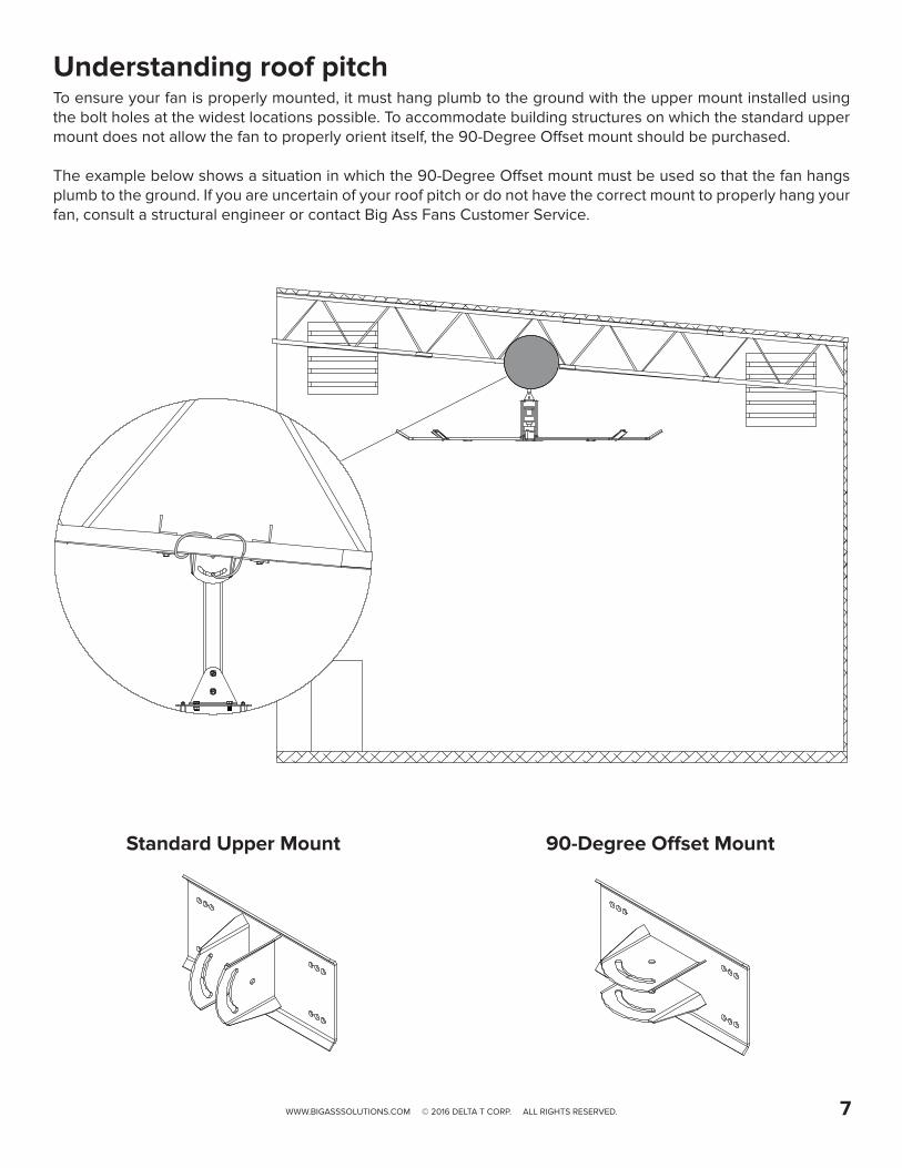
Standard Upper Mount 90-Degree Offset Mount
Understanding roof pitchTo ensure your fan is properly mounted, it must hang plumb to the ground with the upper mount installed using the bolt holes at the widest locations possible. To accommodate building structures on which the standard upper mount does not allow the fan to properly orient itself, the 90-Degree Offset mount should be purchased.
The example below shows a situation in which the 90-Degree Offset mount must be used so that the fan hangs plumb to the ground. If you are uncertain of your roof pitch or do not have the correct mount to properly hang your fan, consult a structural engineer or contact Big Ass Fans Customer Service.

WWW.BIGASSSOLUTIONS.COM © 2016 DELTA T CORP. ALL RIGHTS RESERVED.8
Understanding airflow patternsCorrect fan placement is crucial for maximizing airflow distribution while adhering to safety standards.
Airflow in an open areaThe airflow moves from the fan toward the floor. When airflow hits the floor, it moves outward in all directions. The deflection of air off the floor is called a “floor jet.”
Airflow in an enclosed areaThe floor jet radiates outward until it reaches the walls, which deflect the jet upward. After it hits the ceiling, the upward flow is directed inward to the low pressure area above the fan where it is then pulled down toward the floor. This creates a convection-like air current that gathers momentum. Once this current is established, the fan begins to move air outside the current, escalating its cooling effects.
Airflow with multiple fansWhere there are multiple fans appropriately spaced, the expanding jets of adjacent fans meet to create a pressure zone. The pressure zone acts like a wall, causing each fan to behave like a single enclosed fan. Typically, a single fan’s performance will increase when working in conjunction with other fans.
Airflow with streamlined obstructionObstructions on the floor tend to block the horizontally moving air. Thin or streamlined obstructions do not block much airflow, regardless of size. The air tends to flow smoothly around these obstructions, losing little momentum, and leaving only a small stagnant area behind the obstruction.
Airflow with wide, blunt obstructionA wide, blunt, or flat-faced obstruction forces the air to change direction, turning upward and outward. There is a stagnant area behind these obstructions that is wider and higher than the obstructions themselves.

WWW.BIGASSSOLUTIONS.COM © 2016 DELTA T CORP. ALL RIGHTS RESERVED. 9
Powerfoil Plus airflowThe Powerfoil Plus winglet creates a jet of air that flows outward at a 45° angle, passing over floor obstructions and delivering airflow in a much broader pattern. When planning fan placement, consider this fan’s larger coverage area. Note: PowerfoilPlus winglets are optional and may not be included in your fan order.
General airflow tipsBelow are some techniques that make a dramatic difference in congested areas of your facility. Treat air like water, and scoop, direct, and channel it to where it is needed most. Note: Powerfoil Plus winglets deliver air from a much higher angle, resolving many of the issues outlined below.
• Make sure people are not hidden behind structures that would block airflow. This may seem obvious, but work areas are routinely blocked by shelving, crates, and machinery.
• Position large obstructions so that their smallest profiles are perpendicular to the direction of air movement. For example, a sheet metal press brake might have five times the frontal area if it is facing the airflow rather than if it is turned sideways.
• Wherever possible, position welding curtains, partitions, sheet materials, etc., to scoop air into the work area rather than deflect it.
• Take advantage of the air moving near the floor by creating ground level openings in your work area. It is better to have a work area blocked by materials stacked to the ceiling with an opening below than to have low stacks 3 ft (0.9 m) to 6 ft (1.8 m) high sitting on the floor.

WWW.BIGASSSOLUTIONS.COM © 2016 DELTA T CORP. ALL RIGHTS RESERVED.10
INSTALLATIONWARNING: The fan should not be installed unless the structure on which the fan is to be mounted is of sound construction, undamaged, and capable of supporting the loads of the fan and its method of mounting. A structural engineer should verify that the structure is adequate prior to fan installation. Verifying the stability of the mounting structure is the sole responsibility of the customer and/or end user, and Big Ass Fans hereby expressly disclaims any liability arising therefrom, or arising from the use of any materials or hardware other than those supplied by Big Ass Fans or otherwise specified in these installation instructions.
CAUTION: Before beginning installation, confirm that you have the appropriate mount for your roof pitch.
WARNING: Ensure there are no persons below the fan unit during installation!
OverviewBig Ass Fans can only be hung from an I-beam or angle irons. Consult a structural engineer for installation methods not covered in this manual. Follow the steps on the following pages to install your fan.
I-Beam Angle Irons• It is not recommended to mount a Big Ass Fan
to a fabricated I-beam. Do not direct mount the fan to an I-beam. The I-beam on which the fan will mount must be part of the existing building structure.
• Do not install the fan from a single purlin, truss, or bar joist.
• Unsupported angle iron spans should not exceed 12 ft (3.7 m).
• The angle irons must be fastened to the roof structure at each end.

WWW.BIGASSSOLUTIONS.COM © 2016 DELTA T CORP. ALL RIGHTS RESERVED. 11
outer holesmiddle holesinner holes
Upper Mount (top view)
1a. Prepare I-BeamATTENTION
If you are mounting your fan to angle irons, proceed to the following page.
Measure the flange width of the I-beam from which the fan will be hung. Select the mounting holes that match the flange width of the I-beam from the diagrams below.
Proceed to step 2.
Small Upper Mount 13-3/4’’ x 10” (349 mm x 258 mm)
I-Beam Flange Width Mounting Holes
5” to 6-5/8” (127 to 168 mm)
Inner holes
> 6-5/8” to 8-1/4” (> 168 to 210 mm)
Middle holes
> 8-1/4” to 9-7/8” (> 210 to 250 mm)
Outer holes
Large Upper Mount18-1/2’’ x 10” (470 mm x 258 mm)
I-Beam Flange Width Mounting Holes
9-7/8” to 11-3/8” (250 to 289 mm)
Inner holes
> 11-3/8” to 13” (> 289 to 330 mm)
Middle holes
> 13” to 14-5/8” (> 330 to 371 mm)
Outer holes

WWW.BIGASSSOLUTIONS.COM © 2016 DELTA T CORP. ALL RIGHTS RESERVED.12
1b. Prepare the Angle IronsCAUTION: Do not install the fan from a single purlin, truss, or bar joist.
CAUTION: Unsupported angle iron spans should not exceed 12 ft (3.7 m).
CAUTION: The angle irons must be fastened to the roof structure at each end.
If you are mounting your fan to an I-Beam, see the previous page. Consult a structural engineer for installation methods not covered in this manual.
A. Select proper angle ironsFollow the table below when selecting angle irons for fan installation. Note: Angle irons and angle iron hardware are not included with the fan.
Angle iron span(between mounting points)
Minimum Angle Iron dimensions(W x H x T)
Number of angle irons needed
6 ft (1.8 m) or less 2.5” (6.4 cm) x 2.5” (6.4 cm) x 0.25” (0.6 cm) 2
6 ft to 8 ft (1.8 m to 2.4 m) 3” (7.6 cm) x 3” (7.6 cm) x 0.25” (0.6 cm) 2
8 ft to 12 ft (2.4 m to 3.7 m) 3” (7.6 cm) x 3” (7.6 cm) x 0.25” (0.6 cm) 4*
*Two pairs of angle irons needed.
6 ft (1.8 m) or less
over 6–8 ft (1.8–2.4 m)
over 8–12 ft (2.4 m–3.7 m)
Angle Iron Side View (see table for dimensions)
Width
HeightThickness

ab
bc
WWW.BIGASSSOLUTIONS.COM © 2016 DELTA T CORP. ALL RIGHTS RESERVED. 13
B. Pre-drill angle ironsBefore drilling the angle irons, confirm that you have the appropriate mount to accommodate the roof pitch of your mounting structure.
Drill two Ø9/16” (1.4 cm) holes exactly 5-3/8” (13.7 cm) apart in the centers of two angle irons.
Measure the distance between the mounting points of the roof structure that the angle irons will span. Measure the same distance on the angle irons and drill Ø9/16” (1.4 cm) holes through each end of the angle irons. Drill holes in two angle irons if the span is 8 ft (2.4 m) or less. Drill holes in four angle irons if span is greater than 8 ft (2.4 m).
C. Fasten angle irons together (if span is longer than 8 ft [2.4 m])If the angle iron span is 8 ft (2.4 m) or less, skip this step and proceed to step D.
If the angle iron span is longer than 8 ft (2.4 m), use double angle irons. Locate the center of the angle iron length. Drill a Ø9/16” (1.4 cm) hole through the center of the vertical wall of the angle iron. Drill a total of four angle irons.
Place two drilled angle irons back to back. Fasten the angle irons together with Ø1/2-13 Grade 8 hardware. Align the angle irons to each other and tighten the bolts to 40 ft·lb (54.2 N·m) using a torque wrench and 3/4” socket.
Repeat this step for the remaining two angle irons.
Proceed to step D.
Grade 8 Hardware (Installer-Supplied):a. (2) 1/2-13 Boltb. (4) 1/2” Washerc. (2) 1/2-13 Nylock Nut
Mount with extension tube: 5-3/8’’ (13.7 cm) Direct mount: 5-1/2’’ (14 cm)
Distance between roof structure mounting points
A1/2 AØ 9/16’’ (1.4 cm)
Side view

Double Angle Irons
a
b
cb
d
Square Washer
Thickness: 1/4” (6 mm)
3” (7.6 cm)
3” (7.6 cm)
Ø 9/16” (1.4 cm)
a
b
cbd
Vertical walls are to the outside
Single Angle Irons
WWW.BIGASSSOLUTIONS.COM © 2016 DELTA T CORP. ALL RIGHTS RESERVED.14
D. Fasten angle irons to roof structure mounting points
Single Angle IronFasten the angle irons to the roof structure mounting points at each end with Grade 8 hardware as shown. Do not tighten the hardware until the upper mount has been mounted to the angle irons (step 5). We recommend orienting the angle irons so that the horizontal legs are facing each other (or the vertical legs are on the outside). Proceed to step 5.
Grade 8 Hardware (Installer-Supplied):a. (4) 1/2-13 Boltb. (8) 1/2” Washerc. (4) 3” Square Washer (supplied; see diagram) d. (4) 1/2-13 Nylock Nut
Double Angle IronFasten the angle irons to the roof structure mounting points at each end with Grade 8 hardware as shown. The angle irons with fan mounting holes should be positioned on the inside, facing each other. Do not tighten the hardware until the upper mount has been mounted to the angle irons.
Grade 8 Hardware (Installer-Supplied):a. (8) 1/2-13 Boltb. (16) 1/2” Washerc. (8) 3” Square Washer (supplied; see diagram) d. (8) 1/2-13 Nylock Nut

WWW.BIGASSSOLUTIONS.COM © 2016 DELTA T CORP. ALL RIGHTS RESERVED. 15
2. Directly Mount Main Fan Unit to Angle IronsATTENTION
If you are installing the fan with an extension tube, skip to step 3a (I-beam) or 3b (angle irons).
CAUTION: The main fan unit is heavy. Use caution when raising it. A 24-ft (7.3-m) fan weighs a maximum of 415 lbs (188 kg). A suitable means for lifting the weight of the fan, such as a scissor lift, and at least two (2) installation personnel will be required.
Attach the main fan unit directly to the angle irons with the Main Fan Unit Hardware. Consult the diagram below for distances between the angle irons. Tighten the bolts to 40 ft·lb (54.2 N·m) using a torque wrench and 3/4” socket.
After securing the main fan unit to the angle irons, tighten all the bolts securing the angle irons to the roof structure to 40 ft·lb (54.2 N·m) using a torque wrench and 3/4” socket.
Proceed to step 5.
Main Fan Unit Hardware:a. (4) 1/2-13 x 1-3/4” GR 8 Bolt b. (8) 1/2’’ Flat Washerc. (4) 1/2-13 Nylock Nut
a
b
b
c
5 1/2”(14 cm)
5 1/2”(14 cm)

Side View
a
b
d
e
b
c
WWW.BIGASSSOLUTIONS.COM © 2016 DELTA T CORP. ALL RIGHTS RESERVED.16
3a. Attach Upper Mount to I-BeamIf you are mounting the fan to angle irons, skip to step 3b on the following page.
Note: Spacers are only used on I-Beams when the beam flange exceeds 3/8” (1 cm).
Secure the upper mount to the I-beam with the Upper Mount Hardware. Tighten the bolts to 40 ft·lb (54.2 N·m) using a torque wrench and 3/4” socket.
Proceed to step 4.
Upper Mount Hardware:a. (4) 1/2-13 x 2” GR 8 Boltb. (8) 1/2’’ Flat Washerc. (4) 1/2-13 Nylock Nutd. (2) Beam Clipe. (2) Spacer

Note: Dashed lines represent angle irons.
10-7/8” (27.6 cm)
Small Upper Mount 13-3/4’’ (34.9 cm) x
9-5/8” (24.4 cm)
15-5/8” (39.7 cm)
Large Upper Mount 18-1/2’’(46.9 cm) x 9-5/8”(24.4 cm)
5.38” (13.7 cm)
5.38” (13.7 cm)
WWW.BIGASSSOLUTIONS.COM © 2016 DELTA T CORP. ALL RIGHTS RESERVED. 17
3b. Attach Upper Mount to Angle IronsSecure the upper mount directly to the angle irons with the Upper Mount Hardware as shown. The angle irons should be aligned with the outermost holes of the upper mount. Consult the diagrams below for distances between the angle irons. Do not use beam clips on angle irons!
Tighten the bolts to 40 ft·lb (54.2 N·m) using a torque wrench and 3/4” socket. After attaching the upper mount to the angle irons, tighten all the bolts securing the angle irons to the roof structure to 40 ft·lb (54.2 N·m).
Proceed to step 4.
Upper Mount Hardware:a. (4) 1/2-13 x 2” GR 8 Bolt b. (8) 1/2’’ Flat Washerc. (4) 1/2-13 Nylock Nut
The angle irons should be aligned with the outermost holes on the upper mount. Do not use beam clips on angle irons!
a
b
c
b
Side View

WWW.BIGASSSOLUTIONS.COM © 2016 DELTA T CORP. ALL RIGHTS RESERVED.18
4. Attach the Extension TubeFasten the extension tube to the upper mount with the Extension Tube Hardware. Ensure the extension tube is hanging plumb to the ground, and then tighten the hardware so that it is snug, but not fully tightened.
Note: If the mounting structure requires a non-standard length of extension tube, see “Cutting the Extension Tube.”
Extension Tube Hardware:a. (2) 1/2-13 x 4-1/2’’ GR 8 Bolt b. (4) 1/2’’ Flat Washerc. (2) 1/2-13 Nylock Nut
5. Secure the Safety CableATTENTION
The safety cable is a crucial part of the fan and must be installed correctly. If you have any questions, call Customer Service for assistance.
Note: If your fan installation includes an extension tube, the safety cable is already attached to the extension tube. If you are mounting the fan without an extension tube, the safety cable is packed separately.
I-Beam mount
Secure the safety cable by wrapping it around the I-beam and connecting the looped ends with the shackle as shown. The cable must be drawn tightly around the I-beam, leaving as little slack as possible. If possible, the shackle should be on the topside of the I-beam. Securely tighten the shackle.
Angle iron mount (with extension tube)
Secure the safety cable by wrapping it around the angle irons and connecting the looped ends with the shackle as shown. The cable must be drawn tightly around the angle irons, leaving as little slack as possible. If possible, the shackle should be on the topside of the angle irons. Securely tighten the shackle.
Angle iron mount (no extension tube)
Route the cable through the motor frame and around the angle irons as shown. Connect the looped ends of the cable with the shackle. The cable must be drawn tightly around the angle irons, leaving as little slack as possible. If possible, the shackle should be on the topside of the angle irons. Securely tighten the shackle.
abbc

WWW.BIGASSSOLUTIONS.COM © 2016 DELTA T CORP. ALL RIGHTS RESERVED. 19
6. Attach Lower YokeAttach the lower yoke to the bottom of the extension tube with the Lower Yoke Hardware as shown. Tighten the hardware so that it is snug, but not fully tightened.
Lower Yoke Hardware:a. (2) 1/2-13 x 4-1/2’’ GR 8 Boltb. (4) 1/2’’ Flat Washerc. (2) 1/2-13 Nylock Nut
7. Attach Main Fan Unit CAUTION: The main fan unit is heavy. Use caution when raising it.
Attach the main fan unit to the lower yoke with the Main Fan Unit Hardware. Do not rest the main fan unit on the ground! Make sure the lower cable is positioned between the lower yoke brackets as shown on the right.
Tighten the bolts to 40 ft·lb (54.2 N·m) using a torque wrench and 3/4” socket. Do not discard the main fan unit packaging. It should be used if the fan is ever moved or relocated.
Main Fan Unit Hardware:a. (4) 1/2-13 x 1-3/4” GR 8 Boltb. (8) 1/2’’ Flat Washerc. (4) 1/2-13 Nylock Nut
ab
c b
a
b
c
b
WWW.BIGASSSOLUTIONS.COM © 2016 DELTA T CORP. ALL RIGHTS RESERVED.20
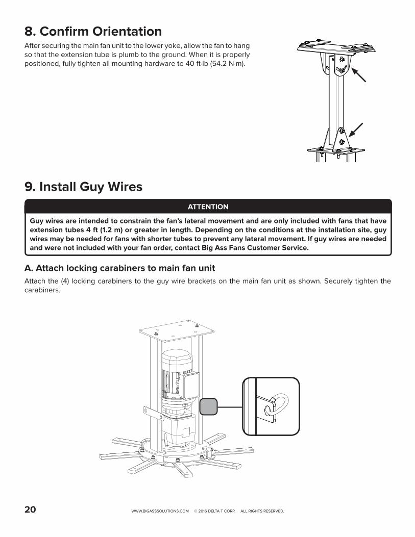
8. Confirm OrientationAfter securing the main fan unit to the lower yoke, allow the fan to hang so that the extension tube is plumb to the ground. When it is properly positioned, fully tighten all mounting hardware to 40 ft·lb (54.2 N·m).
9. Install Guy WiresATTENTION
Guy wires are intended to constrain the fan’s lateral movement and are only included with fans that have extension tubes 4 ft (1.2 m) or greater in length. Depending on the conditions at the installation site, guy wires may be needed for fans with shorter tubes to prevent any lateral movement. If guy wires are needed and were not included with your fan order, contact Big Ass Fans Customer Service.
A. Attach locking carabiners to main fan unitAttach the (4) locking carabiners to the guy wire brackets on the main fan unit as shown. Securely tighten the carabiners.

WWW.BIGASSSOLUTIONS.COM © 2016 DELTA T CORP. ALL RIGHTS RESERVED. 21
B. Attach beam clampsFor best results, the guy wires should be installed at 45° in the X-Y, Y-Z, and X-Z planes as shown below. If the angle deviates by more than 15°, contact Customer Service for assistance.
Attach the beam clamp to the mounting structure. The guy wire should be approximately 45° from the horizontal plane. Place the beam clamp accordingly. Fully tighten the set screw to secure the clamp.
Fasten the small eyebolt and nut onto the beam clamp. The nut will be on the outside of the beam clamp. Loop the crimped end of the guy wire into the locking carabiner and secure to the eyebolt as shown. Securely tighten the carabiner.
Guy Wire Hardware*:a. 1/4” Beam Clampb. 1/4-20 x 1” Eyeboltc. 1/4-20 Hex Nutd. Locking Carabinere. Guy Wire
* The amount of hardware depends on the fan’s number of blades.
Note: I-beams shown above. Your mounting structure may differ.
Guy Wire
I-Beam
I-Beam
I-Beam
I-Beam
I-Beam
I-Beam
45°
Beam Clamp
e
b
dc
a
Guy Wire
45°

WWW.BIGASSSOLUTIONS.COM © 2016 DELTA T CORP. ALL RIGHTS RESERVED.22
C. Route guy wire through Gripple®
Route the guy wire through the Gripple, the carabiner on the fan, and then back through the Gripple as shown. Do not tighten the Gripple until the remaining guy wires have been installed.
Note: To back the guy wire out of the Gripple, insert 1/16 (1.5 mm) Allen wrench into the small hole on the Gripple.
D. Install remaining guy wires
CAUTION: Over-tightening the guy wires could throw the fan off balance.
Repeat steps B and C to install the three remaining guy wires.
Evenly cinch all four guy wires into place using the Gripples. The guy wires should be taut, evenly spaced around the fan, and away from the path of the airfoils. Maintain a distance of 6” to 8” between the Gripple and the carabiner.
Once all of the guy wires are taut, secure their loose ends with the wire rope clips and torque to 4.5 ft·lb (6.1 N·m). Ensure all electrical cords/cables are unobstructed by the guy wire system.
Wire Rope Clip

U/T1 V/T2 W/T3PE L1 L2 L3
L1
L2
L3
1 2 5 6 13A13B13C 1 4 30 1 6 1 725 4 1 11 2 5 6 13A13B13C 1 4 30 1 6 1 725 4 1 1
SCA MESCA ME
MR F
RUN
STOP
AUTO FWD
REV
U/T1 V/T2 W/T3PE L1 L2 L3
L1
L2
L3
1 2 5 6 13A13B13C 1 4 30 1 6 1 725 4 1 11 2 5 6 13A13B13C 1 4 30 1 6 1 725 4 1 1
SCA MESCA ME
MR F
RUN
STOP
AUTO FWD
REV
WARNINGDO NOT USE THISDISCONNECT TO
START AND STOP THEFAN. PERMANENT
DAMAGE WILLRESULT!
WARNINGDO NOT USE THISDISCONNECT TO
START AND STOP THEFAN. PERMANENT
DAMAGE WILLRESULT!
WWW.BIGASSSOLUTIONS.COM © 2016 DELTA T CORP. ALL RIGHTS RESERVED. 23
10. Mount the Variable Frequency Drive (VFD)WARNING: To reduce the risk of electric shock, wiring should be performed by a qualified electrician! Incorrect assembly can cause electric shock or damage the motor and the controller! Hazard of electrical shock!
WARNING: The installation of a Big Ass Fan must be in accordance with the requirements specified in this installation manual and with any additional requirements set forth by the National Electric Code (NEC), ANSI/NFPA, and all local codes. Code compliance is ultimately YOUR responsibility!
ATTENTION
If you are mounting the VFD to the fan motor frame instead of the wall (onboard VFD option), skip this step and refer to the instructions that are packaged with the wall controller.
A. Select a Mounting LocationAdhere to the following guidelines when selecting the VFD location:• Install the controller on a flat surface that is readily accessible, free from vibration, and where there is adequate
distance from foreign objects or moving equipment.• Do not mount any controller adjacent to or above a heat source or heat-producing equipment.• The ambient temperature must be between 14° F (-10° C) and 122° F (50° C) with a relative humidity range of 0 to
95% non-condensing.• Do not expose the controller to a corrosive atmosphere or direct sunlight.• When mounting the controller, keep in mind that the fan should be visible from the controller.• A minimum distance of 6” (15.2 cm) should be maintained between controllers.
B. Mount the VFDIf the controller has been in storage or disconnected from power for more than one year, apply AC supply power to the controller for a period of two hours prior to operation in order to recondition the internal DC bus capacitors.
Mount the VFD to the wall using a #8–#10 screw. Refer to the diagrams below for mounting hole dimensions.
2 hp Controller1 hp Controller
6.25” (159 mm) 6.25” (159 mm)
5.95” (151 mm) 5.95” (151 mm)
10.9
” (2
77 m
m)
10.9
” (2
77 m
m)
9.5
” (2
41 m
m)
9.5
” (2
41 m
m)
5.5
1” (1
40 m
m)
7.3”
(18
5 m
m)
SCA MESCA ME
WARNINGDO NOT USE THISDISCONNECT TO
START AND STOP THEFAN. PERMANENT
DAMAGE WILLRESULT!
U/T1 V/T2 W/T3PE L1 L2 L3
L1
L2
L3
SCA MESCA ME
MR F
RUN
STOP
AUTO FWD
REV
WARNINGDO NOT USE THISDISCONNECT TO
START AND STOP THEFAN. PERMANENT
DAMAGE WILLRESULT!
1 2 5 6 13A 13B 13C 14 30 1 6 1 725 4 111 2 5 6 13A 13B 13C 14 30 1 6 1 725 4 11
WWW.BIGASSSOLUTIONS.COM © 2016 DELTA T CORP. ALL RIGHTS RESERVED.24
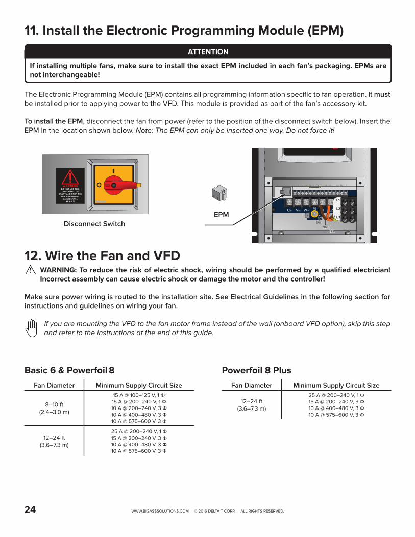
11. Install the Electronic Programming Module (EPM) ATTENTION
If installing multiple fans, make sure to install the exact EPM included in each fan’s packaging. EPMs are not interchangeable!
The Electronic Programming Module (EPM) contains all programming information specific to fan operation. It must be installed prior to applying power to the VFD. This module is provided as part of the fan’s accessory kit.
To install the EPM, disconnect the fan from power (refer to the position of the disconnect switch below). Insert the EPM in the location shown below. Note: The EPM can only be inserted one way. Do not force it!
12. Wire the Fan and VFDWARNING: To reduce the risk of electric shock, wiring should be performed by a qualified electrician! Incorrect assembly can cause electric shock or damage the motor and the controller!
Make sure power wiring is routed to the installation site. See Electrical Guidelines in the following section for instructions and guidelines on wiring your fan.
If you are mounting the VFD to the fan motor frame instead of the wall (onboard VFD option), skip this step and refer to the instructions at the end of this guide.
EPM
ORGBRN
YEL
Disconnect Switch
Powerfoil 8 PlusFan Diameter Minimum Supply Circuit Size
12–24 ft (3.6–7.3 m)
25 A @ 200–240 V, 1 Φ 15 A @ 200–240 V, 3 Φ 10 A @ 400–480 V, 3 Φ10 A @ 575–600 V, 3 Φ
Basic 6 & Powerfoil 8 Fan Diameter Minimum Supply Circuit Size
8–10 ft (2.4–3.0 m)
15 A @ 100–125 V, 1 Φ15 A @ 200–240 V, 1 Φ 10 A @ 200–240 V, 3 Φ 10 A @ 400–480 V, 3 Φ10 A @ 575–600 V, 3 Φ
12–24 ft (3.6–7.3 m)
25 A @ 200–240 V, 1 Φ 15 A @ 200–240 V, 3 Φ 10 A @ 400–480 V, 3 Φ10 A @ 575–600 V, 3 Φ

c
b
b
a
WWW.BIGASSSOLUTIONS.COM © 2016 DELTA T CORP. ALL RIGHTS RESERVED. 25
Hole B
Hole A
Airfoil Retainer
A. Attach winglets to airfoilsNote: Check each airfoil to ensure the AirFence is still securely attached.
Attach a winglet to each airfoil using the Winglet Hardware. Both a Phillips head and flat head screwdriver are required to properly secure the fasteners. Attach winglets to all eight airfoils before attaching the airfoils to the fan.
Winglet Hardware:a. 10-24 x 3/4” Barrelb. 10-24 x 1/2” Bolt
B. Attach airfoils to hubSlide airfoils onto the tabs of the fan hub. The airfoils must be attached to the fan hub with the curved sides facing downward.
Attach the airfoil retainers with the Airfoil Hardware. Moving clockwise around the fan hub, position the airfoil retainers end over end as shown. Hole A of the retainer should be positioned over top of Hole B. Do not tighten the bolts until all the airfoil retainers have been attached!
Tighten the bolts along the outer perimeter to 29 ft·lb (39.3 N·m) using a torque wrench and 1/2” socket. After the outer perimeter bolts are torqued, tighten the bolts along the inner perimeter to 29 ft·lb (39.3 N·m) using a torque wrench and 1/2” socket.
Airfoil Hardware:a. 5/16-18 x 2’’ GR 8 Boltb. 5/16” Flat Washerc. 5/16-18 Nylock Nut
13. Install the AirfoilsATTENTION
If the AirFence™ accessory was included with your fan order, examine each AirFence to ensure it is properly installed on the airfoil.
Disconnect power to the fan before installing the airfoils.
b
a
b
a
WWW.BIGASSSOLUTIONS.COM © 2016 DELTA T CORP. ALL RIGHTS RESERVED.26
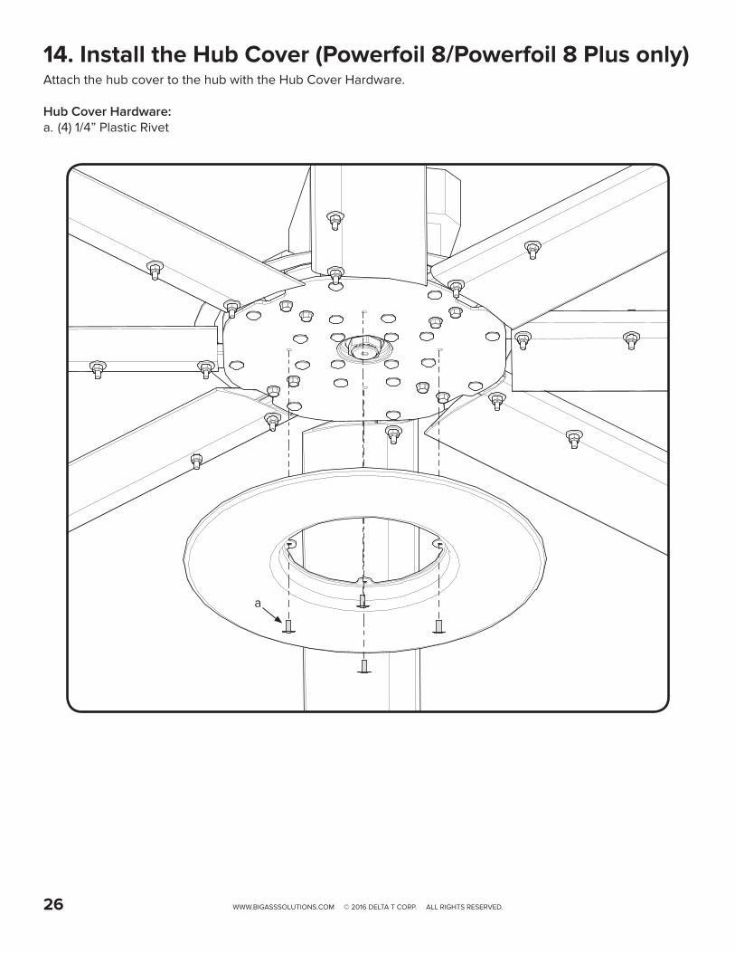
14. Install the Hub Cover (Powerfoil 8/Powerfoil 8 Plus only)Attach the hub cover to the hub with the Hub Cover Hardware.
Hub Cover Hardware:a. (4) 1/4” Plastic Rivet
a

WWW.BIGASSSOLUTIONS.COM © 2016 DELTA T CORP. ALL RIGHTS RESERVED. 27
ELECTRICAL GUIDELINESWARNING: Installation must comply with specifications from National Electrical Codes and standards (NEC, VDE, BSI, etc.) regarding wire types, conductor sizes, branch circuit protection, and disconnecting devices.
WARNING: To avoid a possible shock hazard and/or nuisance tripping caused by induced voltages, unused wires in the conduit must be grounded at both ends. For the same reason, VFD output wires should not share a conduit with another VFDs output leads, or other power circuits (lighting, motors, etc.).
CAUTION: MC or “Metal clad” cable cannot be used for controller output/motor leads. Both stranded and solid core varieties must be avoided. Do not use solid core cable of any size or insulation class for motor wiring. Use of such types of cabling may result in nuisance tripping or premature equipment failure.
Cable typesA variety of cable types are acceptable for variable frequency drive installations. For many installations, unshielded cable is adequate if it can be separated from sensitive circuits. In all cases, parallel runs of control and motor cabling should be avoided when unshielded cable is used. Do not use cable with an insulation thickness of less than 15 mils.• UL installations in 50º C ambient must use 600 V, 75º C or 90º C wire.• UL installations in 40º C ambient should use 600 V, 75º C or 90º C wire.
Acceptable unshielded typesTHHN, THNW, or similar wire is acceptable for drive installations in dry environments if adequate free air space and/or conduit fill rate limits are provided. Do not use THHN or similarly coated wire in wet areas. Any wire chosen must have a minimum insulation thickness of 15 mils and should not have large variations in insulation concentricity.
Acceptable shielded typesThe drain conductor included with shielded cables must be connected to both the motor frame and the PE/Ground terminal of the Variable Frequency Drive.
Location Rating / Type Description
Standard (Option 1)
600 V, 75º C or 90º C (167º F or 194º F) RHH/RHW-2
• Four tinned conductors with XLPE insulation• Foil shield and tinned copper drain wire with 85% braid
coverage• PVC JacketBelden 29501-29507 or equivalent
Standard (Option 2)
Tray rated 600 V, 75º C or 90º C (167º F or 194º F) RHH/RHW-2
• Three tinned copper conductors with XLPE insulation• 5 mil single helical copper tape (25% overlap minimum)
with three bare copper grounds in contact with shield• PVC JacketShawflex 2ACD/3ACD or equivalent
Class I & II Division I & II
Tray rated 600 V, 75º C or 90º C (167º F or 194º F) RHH/RHW-2
• Three bare copper conductors with XLPE insulation with impervious corrugated continuously welded aluminum armor
• Black sunlight resistant PVC jacket overall• Three copper grounds on #10 AWG and smaller
Output disconnectsA device, such as a contactor, that routinely disconnects and reapplies output power to the motor for the purpose of starting and stopping the motor cannot be used.
Recommended wire sizeA minimum of 14 AWG is acceptable for motor leads. Power feeders to controllers must be governed by the fuse size included with the VFD and/or required circuit breaker.
WWW.BIGASSSOLUTIONS.COM © 2016 DELTA T CORP. ALL RIGHTS RESERVED.28
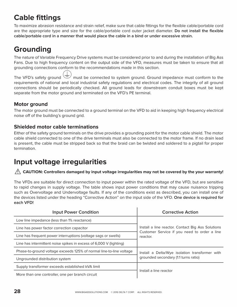
Cable fittingsTo maximize abrasion resistance and strain relief, make sure that cable fittings for the flexible cable/portable cord are the appropriate type and size for the cable/portable cord outer jacket diameter. Do not install the flexible cable/portable cord in a manner that would place the cable in a bind or under excessive strain.
GroundingThe nature of Variable Frequency Drive systems must be considered prior to and during the installation of Big Ass Fans. Due to high frequency content on the output side of the VFD, measures must be taken to ensure that all grounding connections conform to the recommendations made in this section.
The VFD’s safety ground must be connected to system ground. Ground impedance must conform to the requirements of national and local industrial safety regulations and electrical codes. The integrity of all ground connections should be periodically checked. All ground leads for downstream conduit boxes must be kept separate from the motor ground and terminated on the VFD’s PE terminal.
Motor groundThe motor ground must be connected to a ground terminal on the VFD to aid in keeping high frequency electrical noise off of the building’s ground grid.
Shielded motor cable terminationsEither of the safety ground terminals on the drive provides a grounding point for the motor cable shield. The motor cable shield connected to one of the drive terminals must also be connected to the motor frame. If no drain lead is present, the cable must be stripped back so that the braid can be twisted and soldered to a pigtail for proper termination.
Input voltage irregularitiesCAUTION: Controllers damaged by input voltage irregularities may not be covered by the your warranty!
The VFDs are suitable for direct connection to input power within the rated voltage of the VFD, but are sensitive to rapid changes in supply voltage. The table shows input power conditions that may cause nuisance tripping such as Overvoltage and Undervoltage faults. If any of the conditions exist as described, you can install one of the devices listed under the heading “Corrective Action” on the input side of the VFD. One device is required for each VFD!
Input Power Condition Corrective Action
Low line impedance (less than 1% reactance)
Install a line reactor. Contact Big Ass Solutions Customer Service if you need to order a line reactor.
Line has power factor correction capacitor
Line has frequent power interruptions (voltage sags or swells)
Line has intermittent noise spikes in excess of 6,000 V (lighting)
Phase-to-ground voltage exceeds 125% of normal line-to-line voltage Install a Delta/Wye isolation transformer with grounded secondary (1:1 turns ratio)Ungrounded distribution system
Supply transformer exceeds established kVA limit Install a line reactor
More than one controller, one per branch circuit

WWW.BIGASSSOLUTIONS.COM © 2016 DELTA T CORP. ALL RIGHTS RESERVED. 29
Delta secondaryCAUTION: Care must be taken when connecting to a three-phase 240/120 V secondary as shown below. All VFD models rely on internal references made between each incoming phase and ground. To prevent nuisance tripping such as Overvoltage and Undervoltage faults, 200–240 V, three phase VFDs should be connected so that the High leg, or “phase B,” terminates on “L2” of the VFD’s input power terminals.
CAUTION: Avoid installations utilizing supply transformers with a 480V delta secondary (ungrounded, corner grounded, open). Proper fan operation cannot be guaranteed due to a lack of proper phase-to-ground voltage references.
There are many different arrangements available for industrial and commercial power distribution in North America. The most common are the following:
• 575 V/330 V Three-Phase (Wye Secondary). Provides 575 V between phases, and 330 V from each phase to Neutral/Ground.
• 480 V/277 V Three-Phase (Wye Secondary). Provides 480 V between phases, and 277 V from each phase to Neutral/Ground.
• 208 V/120 V Three-Phase (Wye Secondary). Provides 208 V between phases, and 120 V from each phase to Neutral/Ground.
• 240 V/120 V Three-Phase (Delta Secondary). Provides 240 V between phases for three-phase loads, 120 V from phase “A” and “C” to Neutral/Ground, and 208 V from phase “B” to Neutral/Ground as shown below. In this transformer arrangement, phase “B” is commonly referred to as a “Wild Leg” or “High Leg,” and shall be marked accordingly with an orange finish or other effective means per NEC 110.15.
“B” Phase
“C” Phase
Neutral / Ground
“A” Phase
120
V12
0 V
240
V
240
V
240
V
208
V

U/
T1
V/
T2
W/
T3
PE L1 L2 L3
L1
L2
L3
1 2 5 6 13A13B13C 14 30 1
61725 4 1
11 2 5 6 13A13B13C 1
4 30 16
1725 4 1
1
SCAMESCAME
MR F
RUN
STOP
AUTO FWD
REV
WARNINGDO NOT USE THISDISCONNECT TOSTART AND STOP
THE FAN.PERMANENT
DAMAGE WILLRESULT!
U/
T1
V/
T2
W/
T3
PE L1 L2 L3
L1
L2
L3
1 2 5 6 13A13B13C 14 30 1
61725 4 1
11 2 5 6 13A13B13C 1
4 30 16
1725 4 1
1
SCAMESCAME
MR F
RUN
STOP
AUTO FWD
REV
WARNINGDO NOT USE THISDISCONNECT TOSTART AND STOP
THE FAN.PERMANENT
DAMAGE WILLRESULT!
U/
T1
V/
T2
W/
T3
PE L1 L2 L3
L1
L2
L3
1 2 5 6 13A13B13C 14 30 1
61725 4 1
11 2 5 6 13A13B13C 1
4 30 16
1725 4 1
1
SCAMESCAME
MR F
RUN
STOP
AUTO FWD
REV
WARNINGDO NOT USE THISDISCONNECT TOSTART AND STOP
THE FAN.PERMANENT
DAMAGE WILLRESULT!
U/
T1
V/
T2
W/
T3
PE L1 L2 L3
L1
L2
L3
1 2 5 6 13A13B13C 14 30 1
61725 4 1
11 2 5 6 13A13B13C 1
4 30 16
1725 4 1
1
SCAMESCAME
MR F
RUN
STOP
AUTO FWD
REV
WARNINGDO NOT USE THISDISCONNECT TOSTART AND STOP
THE FAN.PERMANENT
DAMAGE WILLRESULT!
U/
T1
V/
T2
W/
T3
PE L1 L2 L3
L1
L2
L3
1 2 5 6 13A13B13C 14 30 1
61725 4 1
11 2 5 6 13A13B13C 1
4 30 16
1725 4 1
1
SCAMESCAME
MR F
RUN
STOP
AUTO FWD
REV
WARNINGDO NOT USE THISDISCONNECT TOSTART AND STOP
THE FAN.PERMANENT
DAMAGE WILLRESULT!
U/
T1
V/
T2
W/
T3
PE L1 L2 L3
L1
L2
L3
1 2 5 6 13A13B13C 14 30 1
61725 4 1
11 2 5 6 13A13B13C 1
4 30 16
1725 4 1
1
SCAMESCAME
MR F
RUN
STOP
AUTO FWD
REV
WARNINGDO NOT USE THISDISCONNECT TOSTART AND STOP
THE FAN.PERMANENT
DAMAGE WILLRESULT!
U/
T1
V/
T2
W/
T3
PE L1 L2 L3
L1
L2
L3
1 2 5 6 13A13B13C 14 30 1
61725 4 1
11 2 5 6 13A13B13C 1
4 30 16
1725 4 1
1
SCAMESCAME
MR F
RUN
STOP
AUTO FWD
REV
WARNINGDO NOT USE THISDISCONNECT TOSTART AND STOP
THE FAN.PERMANENT
DAMAGE WILLRESULT!
U/
T1
V/
T2
W/
T3
PE L1 L2 L3
L1
L2
L3
1 2 5 6 13A13B13C 14 30 1
61725 4 1
11 2 5 6 13A13B13C 1
4 30 16
1725 4 1
1
SCAMESCAME
MR F
RUN
STOP
AUTO FWD
REV
WARNINGDO NOT USE THISDISCONNECT TOSTART AND STOP
THE FAN.PERMANENT
DAMAGE WILLRESULT!
WWW.BIGASSSOLUTIONS.COM © 2016 DELTA T CORP. ALL RIGHTS RESERVED.30
Branch circuit protectionCAUTION: VFDs may not be daisy chained on a branch circuit without providing either one fused disconnect or circuit breaker per controller.
The VFD does not contain individual branch circuit over-current protection. Local code and/or NEC requirements may not permit installation of multiple VFDs on a shared feeder. Confirm prior to installation.
Electrical Distribution Panel
Electrical Distribution Panel

U/T1 V/T2 W/T3PE L1 L2 L3
1 2 5 6 13A 13B 13C 1 4 30 16 1 725 4 1 11 2 5 6 13A 13B 13C 1 4 30 16 1 725 4 1 1
L1
L2
L3
PAM-SD
MR F
RUN
STOP
AUTO FWD
REV
WWW.BIGASSSOLUTIONS.COM © 2016 DELTA T CORP. ALL RIGHTS RESERVED. 31
VFD Wiring: ESFR (Early Suppression Fast Response)WARNING: Improper installation can cause electric shock or damage to the motor and controller. A qualified electrician should perform the installation.
If installing the fan in the United States, the fan must be installed per the following National Fire Protection Association (NFPA) guidelines:
• The fan must be centered approximately between four adjacent sprinklers.• The vertical distance from the fan to the sprinkler deflector must be at least 3 ft (91.4 cm).• The fan must be interlocked to shut down immediately upon receiving a waterflow signal from the alarm
system. The fire relay included with the fan is needed only if the fan will be installed in a building that has a fire sprinkler system. The fire relay integrates the fan with the sprinkler system and shuts down the fan upon receiving an alarm signal from the system. If the building in which the fan will be installed has a sprinkler system, you must install the relay according to the instructions below.
A contact closure across the digital input terminals 4 and 13A will result in fan shutdown. The included relay uses a Normally Open (N.O.) contact as shown below. The relay coil must be energized by the FACP for fan shutdown. Optionally, the normally closed (N.C.) relay contact can be used. The relay coil must remain energized by the FACP for fan operation. This would be considered a fail safe or fail open wiring arrangement. Two additional relay coil leads are provided to facilitate supervision pass-through where required.
Relay is mounted to the backside of the access cover.
An alarm condition will stop the fan and issue an “F_EF” external fault on the controller’s display.
Relay Coil/Contact Details
White (X2)
(-) C Blue
NC Yellow
Red (X2) (+) NO Orange
Coil: 20–32 VDC @ 20 mA
Terminals 4 & 13A for ESFR Relay
From Main FACP or NAC Box if Applicable
BLU
ORG
REDWHT
YEL

U/T1 V/T2 W/T3PE L1 L2 L3
N
1 2 5 6 13A13B13C 14 30 16 1725 4 111 2 5 6 13A13B13C 14 30 16 1725 4 11
L1
L2
U/T1 V/T2 W/T3PE L1 L2 L3
N
1 2 5 6 13A13B13C 14 30 16 1725 4 111 2 5 6 13A13B13C 14 30 16 1725 4 11
L1
L2
WWW.BIGASSSOLUTIONS.COM © 2016 DELTA T CORP. ALL RIGHTS RESERVED.32
VFD Wiring: 100–125 V & 200–240 V, 1 Ф ControllerWARNING: Wait three minutes after disconnecting before servicing!
WARNING: Improper installation can cause electric shock or damage to the motor and controller. A qualified electrician should perform the installation.
The diagrams below shows wiring options for a 100–125 V and 200–240 V, single-phase VFD. Note: The VFD does not contain fusing! Power must be supplied to this controller via a dedicated circuit breaker or properly fused disconnect!
200–240 V, 1 Φ, 50/60 Hz ControllersThe neutral terminal is not used when wiring the VFD for 200–240 V, 1 Φ. A disconnect and EMI filter are included with this VFD.
100–125 V, 1 Φ, 50/60 Hz Controllers (Optional)The L2 terminal is not used when wiring the VFD for 100–125 V, 1 Φ. A disconnect is included with this VFD.
AC Input Wiring 2W plus GND
Motor Output Wiring 3W plus GND
AC Input Wiring 2W plus GND
Motor Output Wiring 3W plus GND
BLK
BLKRED
RED GRN/YEL
GRN/YEL
BLU
BLK
WHT
GRN/YEL
BLK
RED GRN/YEL
BLU

U/T1 V/T2 W/T3PE L1 L2 L3
1 2 5 6 13A13B13C 14 30 16 1725 4 111 2 5 6 13A13B13C 14 30 16 1725 4 11
L1
L2
L3
U/T1 V/T2 W/T3PE L1 L2 L3
1 2 5 6 13A13B13C 14 30 16 1725 4 111 2 5 6 13A13B13C 14 30 16 1725 4 11
L1
L2
L3
WWW.BIGASSSOLUTIONS.COM © 2016 DELTA T CORP. ALL RIGHTS RESERVED. 33
VFD Wiring: 200–240 V, 3 Ф ControllerWARNING: Wait three minutes after disconnecting before servicing!
WARNING: Improper installation can cause electric shock or damage to the motor and controller. A qualified electrician should perform the installation.
The diagrams below shows wiring options for a 200–240 V, three-phase VFD. Note: The VFD does not contain fusing! Power must be supplied to this controller via a dedicated circuit breaker or properly fused disconnect!
200–240 V, 3 Φ, 50/60 Hz ControllersA disconnect is included with the VFD for 200–240 V, 3 Φ. An EMI filter is not included with this VFD.
Optional 1 Φ Wiring for 200–240 V, 3 Φ, 50/60 Hz ControllersThe L3 terminal is not used when wiring the VFD for 200–240 V, 1 Φ. A disconnect is included with the VFD. An EMI filter is not included with this VFD.
AC Input Wiring 3W plus GND
Motor Output Wiring 3W plus GND
AC Input Wiring 2W plus GND
Motor Output Wiring 3W plus GND
BLK
RED
GRN/YEL
BLK
RED GRN/YEL
BLU
BLK
RED
GRN/YEL
BLK
RED GRN/YEL
BLU
U/T1 V/T2 W/T3PE L1 L2 L3
1 2 5 6 13A13B13C 14 30 16 1725 4 111 2 5 6 13A13B13C 14 30 16 1725 4 11
L1
L2
L3
U/T1 V/T2 W/T3PE L1 L2 L3
1 2 5 6 13A13B13C 14 30 16 1725 4 111 2 5 6 13A13B13C 14 30 16 1725 4 11
L1
L2
L3
WWW.BIGASSSOLUTIONS.COM © 2016 DELTA T CORP. ALL RIGHTS RESERVED.34
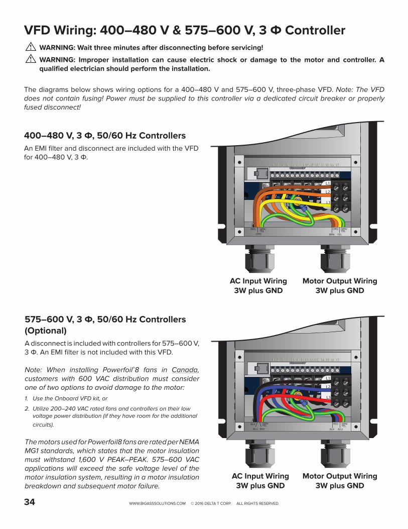
VFD Wiring: 400–480 V & 575–600 V, 3 Ф ControllerWARNING: Wait three minutes after disconnecting before servicing!
WARNING: Improper installation can cause electric shock or damage to the motor and controller. A qualified electrician should perform the installation.
The diagrams below shows wiring options for a 400–480 V and 575–600 V, three-phase VFD. Note: The VFD does not contain fusing! Power must be supplied to this controller via a dedicated circuit breaker or properly fused disconnect!
400–480 V, 3 Φ, 50/60 Hz ControllersAn EMI filter and disconnect are included with the VFD for 400–480 V, 3 Φ.
575–600 V, 3 Φ, 50/60 Hz Controllers (Optional)A disconnect is included with controllers for 575–600 V, 3 Φ. An EMI filter is not included with this VFD.
Note: When installing Powerfoil®8 fans in Canada, customers with 600 VAC distribution must consider one of two options to avoid damage to the motor:1. Use the Onboard VFD kit, or
2. Utilize 200–240 VAC rated fans and controllers on their low voltage power distribution (if they have room for the additional
circuits).
The motors used for Powerfoil8 fans are rated per NEMA MG1 standards, which states that the motor insulation must withstand 1,600 V PEAK–PEAK. 575–600 VAC applications will exceed the safe voltage level of the motor insulation system, resulting in a motor insulation breakdown and subsequent motor failure.
AC Input Wiring 3W plus GND
Motor Output Wiring 3W plus GND
AC Input Wiring 3W plus GND
Motor Output Wiring 3W plus GND
BRN
BRNORG
ORG GRN/YEL
GRN/YEL
YEL
BLK
RED
GRN/YEL
BLK
RED GRN/YEL
BLUBLU

U/T1 V/T2 W/T3PE
L1 L2 L3
1 2 5 6 13A 13B 13C 14 30 16 1725 4 111 2 5 6 13A 13B 13C 14 30 16 1725 4 11
U/T1 V/T2 W/T3PE
L1 L2 L3
1 2 5 6 13A 13B 13C 14 30 16 1725 4 111 2 5 6 13A 13B 13C 14 30 16 1725 4 11
WWW.BIGASSSOLUTIONS.COM © 2016 DELTA T CORP. ALL RIGHTS RESERVED. 35
Daisy Chaining the FansWARNING: Wait three minutes after disconnecting before servicing!
The following illustrations and parameter changes enable daisy chaining of multiple fans. The first fan provides a start/stop contact and 0–10 VDC analog speed reference for the first downstream VFD, which then provides a new start/stop contact and 0–10 VDC analog speed reference for the following downstream VFD. This preferred method of linking the VFDs together ensures minimal signal loss of command signals in larger multi-fan systems.
Assertion Level Switch (ALSW)The VFD ships with the onboard digital I/O configured for Sourcing (PNP) operation. Terminal 4 provides +15 VDC to be used as a supply voltage for user-supplied switches and accessories. For this 3-wire daisy chaining application, the downstream VFDs must be switched to Sinking (NPN) operation. Terminal 4 will then provide a DC common connection and allow the analog signal and start/stop signal to share that common. The Assertion Level switch above terminal 4 must be switched from (+) to (-) on all downstream VFDs for proper daisy chaining operation prior to powerup, parameter changes, and operation.
Parameter changes (for first controller) Parameter changes (for downstream VFDs)Parameter Description Parameter Description
Relay Output FunctionChange from “0” for None to “1” for Run.
Assertion LevelChange from “2” for High to “1” for Low
TB-30 OutputChange from “0” for None to “1” for 0–10 VDC output (scaled to drive output frequency).
Start Control SourceChange from “0” for keypad operation to “1” for Terminal Strip.
TB-30 Scaling FrequencyChange to equal the frequency setting of P103 Maximum Frequency.
Standard Reference SourceChange from “0” for keypad operation to “1” for 0–10VDC analog input operation.
Speed at Max SignalChange to equal the frequency setting of P103 Maximum Frequency.
Note: Depending on the AWG and distance of the low voltage wiring, the downstream fans may run slightly slower than the leading fan. If this occurs, P161 Speed at Max Signal can be used to introduce a minor command reference overshoot to compensate for the analog voltage drop. At each downstream fan (beginning with the first), adjust the value of P161 up 0.1–0.2 Hz increments until the fan’s output frequency matches that of the lead fan.
#17 = N.O. Relay Output #17 = N.O. Relay Output
#16 = N.O. Relay Output #16 = N.O. Relay Output#2 = Analog Common
3 conductor shielded cable minimum 20 AWG Stranded (installer-supplied) Recommended
Maximum distance = 200 ft
#30 = 0–10 VDC Output #30 = 0–10 VDC Output
#4 = Digital Common*
0–10 VDC and Start/Stop out to next
downstream controller
#2 = Analog Common
Terminals 2 and 16 shall be tied together on the first VFD.
#1 = Run/Stop Input
#5 = 0–10VDC Input
Terminals 2, 4, and 16 shall all be tied together on all downstream VFDs.
RED REDREDBLK BLKBLK
WHT WHTWHT

W1T3
V1T2
U1T1
W5T9
V5T8
U5T7
V2T5
U2T4
W1T3
V1T2
U1T1
W5T9
V5T8
U5T7
W2T6
V2T5
U2T4
W2T6
WWW.BIGASSSOLUTIONS.COM © 2016 DELTA T CORP. ALL RIGHTS RESERVED.36
Motor Wiring: 9-Lead, Dual Voltage, Wye Motor ConfigurationsThe motor wiring configurations shown below are applicable to 9-lead, dual voltage, wye wound motors rated for 230/460 VAC and 330/600 VAC. Consult the motor nameplate and/or wiring placard for verification of required wiring connections. Motors with terminal blocks require ring terminals and a 7 mm nut driver for termination. The diagrams below include L2 and L3 swap to yield proper motor rotation. Note: Swapping leads to reverse rotation is done only on the output side of the drive.
Low Voltage
200–240 VAC, 50–60 Hz 330–350 VAC, 50–60 Hz
High Voltage
400–480 VAC, 50–60 Hz 575–600 VAC, 50–60 Hz
Jumper bars are provided with the
motorHigh Voltage
Low Voltage
GREEN W/ YELLOW TRACERVA
C fr
om V
FD
BLACK
GREEN W/ YELLOW TRACER
WHITEREDBLACK
WHITERED
VA
C fr
om V
FD

MR F
RUN
STOP
AUTO FW D
REV
MR F
RUN
STOP
AUTO FW D
REV
RUN
STOP
M
R F
MR F
RUN
STOP
AUTO FW D
REV
WWW.BIGASSSOLUTIONS.COM © 2016 DELTA T CORP. ALL RIGHTS RESERVED. 37
OPERATING THE CONTROLLERWARNING: The following startup procedures apply to standard model controllers. Procedures may vary depending on installation options and system automation. The installer should verify proper wiring, terminations, and proper voltage supply before proceeding. High voltage gloves and arc flash protection are recommended.
Starting and stopping the fanThe RUN and STOP buttons control the fan start and stop functions. To start the fan, press the green RUN button. To stop the fan, press the red STOP button.
Adjusting fan speedThe Arrow buttons control speed adjustment. To adjust fan speed, press the Up or Down Arrow button. Single presses will increase or decrease the speed in 1-2% increments. Pressing and holding the Up or Down Arrow button will slowly and continuously adjust fan speed until the button is released.
Reversing direction of fan rotationThe direction of fan rotation can be reversed when the fan is stopped or running. To reverse the direction of rotation, press the Direction button, and then press the Memory/Enter button (as shown on the left). The associated Direction indicator will flash, indicating the pending change.
Drive Idle/Stopped Screen
Fan Speed Percentage Display (73.5% Running FWD)
Typical Fault Message Display(Incoming Line Over-Voltage Shown)
then

WWW.BIGASSSOLUTIONS.COM © 2016 DELTA T CORP. ALL RIGHTS RESERVED.38
OPERATING THE FANBig Ass Fans are the highest quality, most meticulously engineered HVLS fans on the planet, moving a lot of air with their size, not speed. Moving at a low speed means less energy used for operation, translating into more energy savings year-round. Follow the procedures below to ensure the most efficient operation of your Big Ass Fan.
To ensure proper fan rotation:1. Turn on the fan. 2. Verify that the fan is rotating in the counterclockwise direction (when viewed from below). 3. If the fan is not rotating counterclockwise, reverse the direction of rotation. See the previous page for instructions
on changing the direction of rotation.
Heating seasonThe Powerfoil 8 and Basic 6 fan returns heat from the ceiling to floor level more efficiently than small ceiling fans. For maximum energy savings, the fan should be operated continuously during the heating season and should not be operated in reverse (clockwise). Big Ass Fans are designed to operate efficiently at very low speeds, so turning the fan very slowly in the forward direction (counterclockwise) will provide enough air movement to circulate the hot air at the ceiling down to the floor without causing a draft.
Adjust the fan speed to the appropriate starting fan speed listed in the table below.
Floor-to-ceiling height (ft) Starting fan speed Display %< 40 15 Hz 20–30%
≥ 40 20 Hz 30–40%
Stand directly below the tips of the airfoils with hand outstretched. If you feel a draft, slightly decrease the fan speed by 0.5 Hz (1–2%). Repeat until the draft is no longer noticeable.
Cooling seasonThe cooling effect created by the breeze from the Powerfoil 8 and Basic 6 fan keeps occupants comfortable with the thermostat at a higher setting. During the cooling season, every degree higher that the thermostat is reset reduces the energy consumed by the air conditioner by 1.5–2%. To minimize energy usage during the cooling season, operate the fan only when building occupants are present.
Adjust the fan speed to the appropriate starting fan speed listed in the table below.
Floor-to-ceiling height (ft) Starting fan speed Display %< 40 25 Hz 40–50%
≥ 40 40 Hz 60–70%
Increase the speed of the fan until desired air speed or maximum fan speed is reached. In air conditioned facilities, increase the thermostat setting by 2–7° F to save energy.

a
b
WWW.BIGASSSOLUTIONS.COM © 2016 DELTA T CORP. ALL RIGHTS RESERVED. 39
ONBOARD VARIABLE FREQUENCY DRIVEATTENTION
It is the responsibility of the installer to install the fan according to facility and owner standards and all local and national safety codes. Big Ass Fans does not provide additional means of disconnect when the VFD is mounted onboard the fan. If preferred or required by local or national code, additional means of disconnect should be provided by the installer as specified by the owner of the fan or facility manager.
Make sure to route the power wiring to the fan location before installing the VFD!
WARNING: Before servicing the fan, ensure power is disconnected.
Parts and hardwareIf you are missing any parts or hardware, contact Customer Service. Note: The illustrations below are not to scale.
Wall Controller Mounting Plate & Cover
(2) VFD Mounting Bracket
VFD Interface Module1
(2) 1/4”-20 x 1.75” Flange Head Bolt
(2) 1/4”-20 Flange Locknut
(4) 10-24 Pan Head Screw
(2) 6-32 x 1.25” Flat Head Screw
(4) 6-32 x 0.38” Flat Head Screw
(4) 10-24 Nylock Nut
1. Attach mounting bracketsAttach the VFD mounting brackets using the Mounting Bracket Hardware. Do not fully tighten the nuts.
Mounting Bracket Hardware:a. (2) 1/4”-20 x 1.75” Flange Head Boltb. (2) 1/4”-20 Flange Locknut
1. The VFD interface module required for this installation is marked “RK” for Remote Keypad. A nearly identical module is used for BAFWorks® and Dewtect® installations. This module is marked “RO” and is not compatible with remote keypad installations.
Wall Controller & Rubber Gasket

ab
a
To Junction Box (in Wall)
WWW.BIGASSSOLUTIONS.COM © 2016 DELTA T CORP. ALL RIGHTS RESERVED.40
2. Attach VFD and tighten nutsSecure the VFD (provided with the fan) to the mounting brackets using the VFD Hardware. Fully tighten the 1/4” locknuts from the previous step.
VFD Hardware:a. (4) 10-24 Pan Head Screwb. (4) 10-24 Nylock Nut
3. Attach mounting plate WARNING: Ensure the VFD is disconnected from power. Wait three minutes after disconnecting before servicing!
Select a mounting location that is visible from the fan. Remove the two (2) screws and the rubber gasket from the back of the wall controller. Discard the screws. Attach the rubber gasket and the wall controller mounting plate to the junction box in the wall with the 6-32 x 1.25” flat head screws (a). Note: The mounting plate fits a standard junction box (not supplied).
4. Connect to VFDATTENTION
Steps a–g below MUST be completed in the order shown.
a. Make the electrical connections to the VFD as described in the Electrical Installation section.
b. Install the VFD interface module, and then wire the wall controller to the module. Refer to the table and the illustration below for wiring instructions and the appropriate communications cable for your application.
Length of run (controller to VFD) Cable to use
≤ 100 ft (30.5 m)Belden 8332, General Cable C0620, or equivalent with 300 V jacket insulation
100 ft (30.5 m) < x ≤ 328 ft (100 m) 18–16 AWG 4 conductor shielded cable
VFD interface module terminal Description Wall controller terminal1 Wall controller power (-) 2
2 Communication (TXA) TXA
3 No connection --
4 Communication (TXB) TXB
5 Wall controller power (+) 11

1 2 3 4 5
7mm
< (16-26 AWG)
0.5 Nm/ 4.5 lb-in
6 mm
< (16-26 AWG)
0.2 Nm/ 2 lb-in
Mounting Plate
Wall Controller
Controller Cover
a
WWW.BIGASSSOLUTIONS.COM © 2016 DELTA T CORP. ALL RIGHTS RESERVED. 41
c. For proper functionality, set the following VFD parameters in the order shown from the VFD’s main keypad:
Parameter Set to DescriptionP199 00 Unlock EPM to user programming
P100 02 Set start source to wall controller only
P400 01 Set network protocol to wall controller
P166 00 Set PWM frequency to 10 kHz
Note: The P166 setting should only be set to 00 on VFDs mounted to the fan frame as described in these instructions. All other “long lead” installations should remain set to 01.
Note: A control configuration fault (“F_Fnr”) may be displayed after you change P100 or P400. You can ignore this fault by pressing STOP on the main VFD keypad.
d. Power down the fan, and then insert a jumper wire between terminals 1 and 4 on the VFD terminal strip for a drive RUN enable. Do not install the jumper before making the parameter changes listed in the previous step.
e. Secure the lower VFD cover with the four screws and reapply AC power.
f. Rest the wall controller in the controller cover, and then secure the cover to the mounting plate with the 6-32 x 0.38” flat head screws (a).
1. Install module under this tab first.
2. Roll module into position under this tab. Module will click into place.
3. Plug module’s 6-pin connector into the “PL3” socket on the VFD.

M
R F
STOPRUN
M
R F
STOPRUN
M
R F
STOPRUN
REVRUNFWDAUTO
M
R F
STOPRUN
REVRUNFWDAUTO
M
R F
STOPRUN
REVRUNFWDAUTO
M
R F
STOPRUN
M
R F
STOPRUN
WWW.BIGASSSOLUTIONS.COM © 2016 DELTA T CORP. ALL RIGHTS RESERVED.42
OperationWARNING: The following startup procedures apply to standard model controllers. Procedures may vary depending on installation options and system automation. The installer should verify proper wiring, terminations, and voltage supply before proceeding. High voltage gloves and arc flash protection are recommended.
Starting and stopping the fanThe RUN and STOP buttons control the fan start and stop functions.
To start the fan, press the green RUN button.
To stop the fan, press the red STOP button.
Adjusting fan speedThe arrow buttons control speed adjustment.
To adjust fan speed, press the Up or Down arrow button.• Single presses will increase or decrease the speed in 1–2% increments.• Pressing and holding the Up or Down arrow button will slowly and continuously adjust fan
speed until the button is released.
Reversing direction of fan rotationThe direction of fan rotation can be reversed when the fan is stopped or running.
To reverse the direction of rotation, press the Direction button, and then press the Memory/Enter button as shown on the left. The associated direction indicator will flash to indicate the pending change.
then
Drive idle/stopped screen Fan speed percentage display (73.5% running forward)
Typical fault message display (incoming line over-voltage shown)

WWW.BIGASSSOLUTIONS.COM © 2016 DELTA T CORP. ALL RIGHTS RESERVED. 43
MAINTENANCEWARNING – TO REDUCE THE RISK OF FIRE, ELECTRIC SHOCK, OR INJURY TO PERSONS, OBSERVE THE FOLLOWING:
a. Use this unit only in the manner intended by the manufacturer. If you have questions, contact Big Ass Solutions.
b. Before servicing or cleaning unit, switch power off at the service panel, and lock the service disconnecting means to prevent power from being switched on accidentally. When the service disconnecting means cannot be locked, securely fasten a prominent warning device, such as a tag, to the service panel.
When servicing of a component in the fan requires the removal or disconnection of a safety device, the safety device must be reinstalled or remounted as previously installed.
Please take a few moments each year to perform the following preventive maintenance inspection on your fan to ensure its safe and efficient operation. Before contacting Customer Service, try mending the issue using the troubleshooting procedures listed in “General Troubleshooting.” If you have any questions, contact Customer Service.
Annual preventive maintenancePerform the following maintenance procedures each year using the Maintenance Checklist:
1. Check for the presence of the safety cable and shackle. The cable should be wrapped around the I-beam/angle irons leaving as little slack as possible. The shackle should be securely tightened and located on the topside of the I-beam/angle irons.
2. Ensure all mounting bolts are present and torqued to 40 ft·lb (54.2 N·m). There are four bolts for direct mount installations, and 12 bolts for installations with extension tube.
3. Inspect motor terminations inside the junction box and tighten if necessary.4. Check the gear reducer for oil leakage. If leakage is present, contact Customer Service.5. Ensure all bolts securing the airfoils to the fan are present and torqued to 29 ft·lb (39.3 N·m).6. Ensure airfoils are secured to one another by airfoil retainers.7. Ensure the bolts securing the winglets to the airfoils are securely tightened.8. Inspect for signs of corrosion, discoloration, pitting, or flaking of metal.9. Inspect the airfoils and hub for signs of damage or cracks. 10. Check guy wires (if installed) for fraying or damage.
General preventive maintenance• Check all connections in the controller and tighten as needed. Using a vacuum, remove all dust and debris
from the inside and outside of the controller.• Verify proper fan rotation. The fan should be turning counterclockwise when viewed from the floor.• Dust the airfoils, motor, and motor housing. If desired, use a gentle cleaner or degreasing agent to polish the
foils. Do not use Clorox® or other chlorine based cleaners! This could result in the release of toxic/fatal fumes.• Observe the motion of the fan during operation. The fan should not wobble or precess. If any wobble is noticed,
ensure the mounting structure is rigid enough to support the fan and that the guy wires, if used, are sufficiently taut. If guy wires were not used, Big Ass Fans suggests installing them. Contact Customer Service.

WWW.BIGASSSOLUTIONS.COM © 2016 DELTA T CORP. ALL RIGHTS RESERVED.44
Fan Model: Fan Model: Fan Model:
Serial #: Serial #: Serial #:
Location: Location: Location:
Date Initials Date Initials Date Initials
ANNUAL MAINTENANCE CHECKLIST

WWW.BIGASSSOLUTIONS.COM © 2016 DELTA T CORP. ALL RIGHTS RESERVED. 45
GENERAL TROUBLESHOOTINGSome issues can be resolved before requesting service. Review the troubleshooting tips listed below before contacting Customer Service for support.
Customers in the United StatesFor questions about your product or customer service inquiries, please call our toll free number (877-BIG-FANS) or visit www.bigassfans.com/service.
Customers outside of the United StatesFor questions about your product or customer service inquiries, please contact your local Big Ass Solutions representative or fill out a contact form at www.bigassfans.com/service.
Symptom Possible solution(s)
The fan is turning in the wrong direction.
To be effective, the fan should be rotating in the counterclockwise direction when viewed from the floor. If the fan is not rotating in the counterclockwise direction, press the F/R button on the controller.
A popping noise is coming from the fan.
Airfoil noise comes from airfoils that are not tightened to the specified torque.
Disconnect the fan from power, and then tighten the airfoil fasteners to 29 ft·lb (39.3 N·m). If the popping still occurs, verify that the airfoils are not contacting each other. If they are, contact Big Ass Solutions Customer Service.
The fan will not start.
Verify the following:• Make sure that all wires are securely connected.• Verify that supply power is adequate and functional.
If the fan still does not start, contact Customer Service.
The VFD generates radio frequency noise (RF).
VFDs generate RF noise in many ways, but this can be prevented using the proper wiring practices outlined in “Electrical Installation.”
Verify the following:• Do not run your controller and sensitive equipment on the same
power line.
• Ensure proper grounding at the motor, controller, and from the controller to the utility.
If the noise is still present, contact Customer Service.
The motor makes noise when fan speed is increased.
Audible high frequency carrier noise may be an indicator of a stall condition.
Verify motor currents are within limits. Reference the technical specifications in this manual to confirm motor currents for your fan size.
The fan wobbles during operation.
• Verify that the mounting structure is rigid enough to support the fan and that the fan is not being exposed to external air forces.
• If guy wires were installed, confirm proper installation. If guy wires were not installed, contact Customer Service.
Note: Some motor, gearbox, or drive noise is to be expected and is normal.

Cutting the extension tubeCAUTION: Make sure the safety cable is not damaged after cutting and drilling the extension tube!
If your mounting structure requires a non-standard extension tube length, use the guidelines below to cut the extension tube.
IMP
OR
TAN
T
Safe
ty c
able
is a
ttac
hed
here
. D
o no
t cut
or
alte
r th
is e
nd!
BO
TTO
M E
ND
—
CU
T TH
IS E
ND
O
NLY
TOP
EN
D
Leng
thØ
0.5
6”
(1.4
cm)
9/1
6”
or 7
/32”
D
rill P
erm
issi
ble0.78
” (1.
98
cm)
0.78
” (1.
98
cm)
1.5”
(3.8
cm
)
1.5”
(3.8
cm
)
3”
(7.6
2 cm
)3”
(7
.62
cm)
3”
(7.6
2 cm
)
3”
(7.6
2 cm
)
2.8”
(5
.79
cm
)
WWW.BIGASSSOLUTIONS.COM © 2016 DELTA T CORP. ALL RIGHTS RESERVED.46
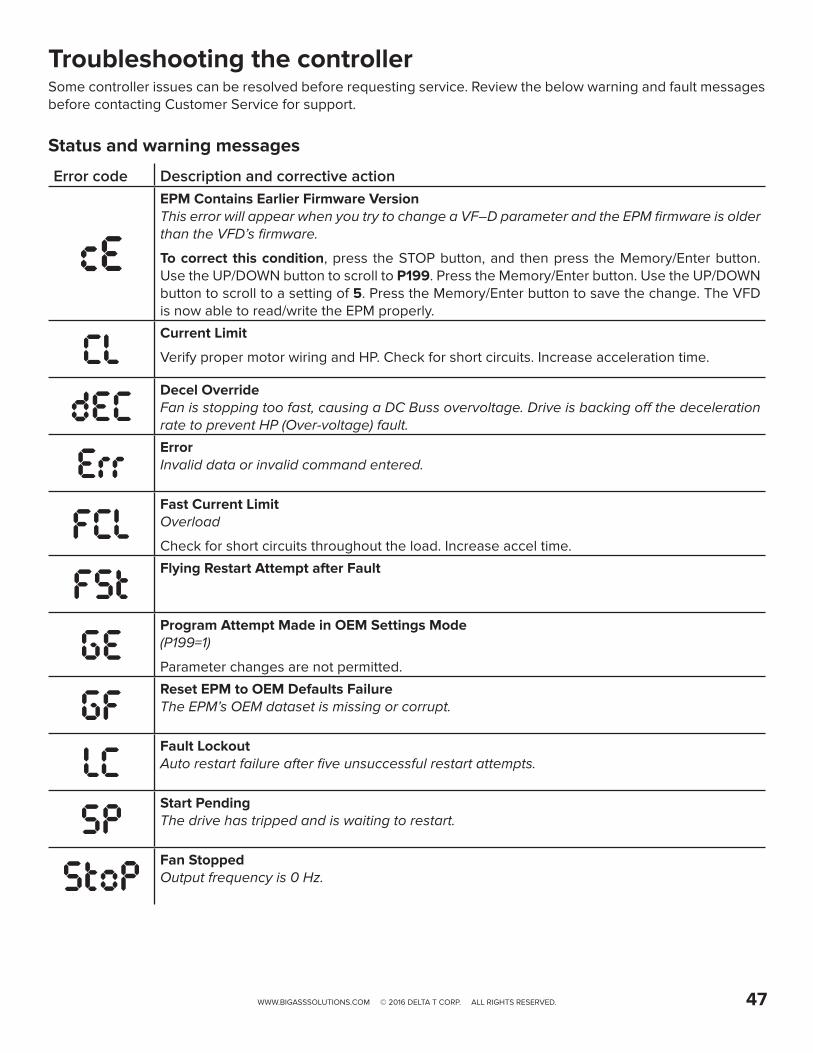
WWW.BIGASSSOLUTIONS.COM © 2016 DELTA T CORP. ALL RIGHTS RESERVED. 47
Troubleshooting the controllerSome controller issues can be resolved before requesting service. Review the below warning and fault messages before contacting Customer Service for support.
Status and warning messages
Error code Description and corrective actionEPM Contains Earlier Firmware VersionThis error will appear when you try to change a VF–D parameter and the EPM firmware is older than the VFD’s firmware.
To correct this condition, press the STOP button, and then press the Memory/Enter button. Use the UP/DOWN button to scroll to P199. Press the Memory/Enter button. Use the UP/DOWN button to scroll to a setting of 5. Press the Memory/Enter button to save the change. The VFD is now able to read/write the EPM properly.
Current Limit
Verify proper motor wiring and HP. Check for short circuits. Increase acceleration time.
Decel OverrideFan is stopping too fast, causing a DC Buss overvoltage. Drive is backing off the deceleration rate to prevent HP (Over-voltage) fault.
ErrorInvalid data or invalid command entered.
Fast Current LimitOverload
Check for short circuits throughout the load. Increase accel time.
Flying Restart Attempt after Fault
Program Attempt Made in OEM Settings Mode(P199=1)
Parameter changes are not permitted.
Reset EPM to OEM Defaults FailureThe EPM’s OEM dataset is missing or corrupt.
Fault LockoutAuto restart failure after five unsuccessful restart attempts.
Start PendingThe drive has tripped and is waiting to restart.
Fan StoppedOutput frequency is 0 Hz.

WWW.BIGASSSOLUTIONS.COM © 2016 DELTA T CORP. ALL RIGHTS RESERVED.48
Fault messages
Error code Description and corrective actionHigh Temperature fault
Check for excessive load or a dirty heatsink. Improve the drive cooling ability.
Assertion Level fault
Check the assertion level switch relative to P120.
Personality faultDrive hardware error
Cycle power, and then reprogram EPM. If the fault will not clear, replace the drive and EPM.
Control faultDrive hardware error
Cycle power, and then reprogram EPM. If the fault will not clear, replace the drive and EPM.
Incompatible EPM faultDrive hardware error
Cycle power, and then reprogram EPM. If the fault will not clear, replace the drive and EPM.
External fault
Digital input programmed for this feature has been energized/de-energized depending on programming. P121-P124
EPM faultEPM is missing or defective.
Replace the EPM.
to
Hardware Failure
Replace the drive.
4–20 mA Signal Loss
Check signal source and wiring, i.e., SmartSense wiring error.
OEM Defaults Data FaultThe OEM parameters in the EPM module do not match the anticipated defaults according to the VFD. This fault may appear immediately upon VFD power-up.
To correct this condition, press the STOP button, and then press the Memory/Enter button. Use the UP/DOWN button to scroll to P199. Press the Memory/Enter button. Use the UP/DOWN button to scroll to a setting of 0. Press the Memory/Enter button to save the change. The VFD is now able to read/write the EPM properly.
High Voltage fault
Check AC incoming power or increase fan deceleration time.
Low Voltage fault
Check AC incoming power

WWW.BIGASSSOLUTIONS.COM © 2016 DELTA T CORP. ALL RIGHTS RESERVED. 49
Error code Description and corrective actionOutput Transistor faultShort circuit, excessive load, excessive cable charging current
Verify correct load (motor HP, motor wiring, cable length, cable type).
Motor Short to Ground
Motor Thermal OLCheck actual motor current against FLA (P108)
Flying Restart faultFailed motor speed sync attempt
Single Phase faultIncoming AC line phase loss
Check supply power.
Start faultStart command was present on powerup.
Cycle start command.
179 diagnostics running display options
Error code Description and corrective actionFault History (n.xxx)
N = 1–8xxx = Fault code
Software Version
Drive ID
Internal Code (x.yz)
DC Buss Voltage (divided by 1.414 = approximate line input voltage)
RMS Equivalent Motor Voltage at Drive Output Terminals
Motor Load (% of drive output rating)

WWW.BIGASSSOLUTIONS.COM © 2016 DELTA T CORP. ALL RIGHTS RESERVED.50
Error code Description and corrective actionActual Motor Current in Amperes
Torque as a Percentage of Motor Rated Torque (vector mode only)
Drive Output Power in kW
Total kWH for Drive Lifetime
Heatsink Temperature Degrees Celsius
0–10 VDC Input Voltage (VDC)
4–20mA Input Current (mA)
Analog Output Level (VDC)
Actual Drive Output Frequency (Hz)
Network Speed Command (Hz)
Total Runtime (hours)
Total Powered-On Time (hours)
Fault History(n.xxx)
N = 1–8xxx = Fault code

WWW.BIGASSSOLUTIONS.COM © 2017 DELTA T CORP. ALL RIGHTS RESERVED. 51
CONTACT USTalk to a Big Ass Fan Expert. Call us at one of the numbers below or visit www.bigasssolutions.com
Customer ServiceUnited States2348 Innovation Drive Lexington, KY 40511USA 877-244-3267+1 859-233-1271
Australia/Oceania35 French StreetEagle Farm, QLD 4009 Australia(07) 3292 0100
EuropeOBELIS S.ABd. Général Wahis, 531030 Brussels, Belgium+32.2.732.59.54
Canada6300 Northwest Dr, Unit 3 Mississauga, ON L4V 1J7Canada 1-844-924-4277
South and Southeast Asia18 Tampines Industrial Crescent #06-07Singapore 528 605 +65 6709 8500
MalaysiaNo 4, Jalan Jururancang U1/21A Hicom Glenmarie Industrial Park40150 Shah Alam, SelangorMalaysia
Manufacturing and WarrantyYou are responsible for providing and paying for shipping when returning a product to Big Ass Solutions for the purpose of recycling under the WEEE directive.
Manufacturing2425 Merchant Street Lexington, KY 40511USA
Warranty and WEEE Returns2251 Innovation DriveLexington, KY 40511USA
Manufacturing2251 Innovation Drive Lexington, KY 40511USA


WWW.BIGASSSOLUTIONS.COM © 2017 DELTA T CORP. ALL RIGHTS RESERVED. 53
CHECK-IN PROCEDURE (Big Ass Fans Certified Installers Only)
Fan placement is to be in accordance with agreed upon original Scope of Work and Layout. If this is to change, please note change and consult Field Service Manager for approval.
Installation techniques have been discussed (type of conduit, L-brackets if required, mounting technique explained). If the extension tubes exceed 4 ft (1.2 m), guy wires are explained and fully understood.
Times in/out, duration, and schedule presented and accepted.
Time (please list the number of employees and total duration of jobs):
Safety rules and regulations have been brought to installer’s attention (e.g., badges, safety harnesses, vests, hard hats, footwear, lock out/tag out, certification processes, work area free of trash and debris, etc.). If there are any areas that are forbidden or secure, they are brought to the supervisor’s attention and instructed not to enter. If there are any special site conditions (i.e., open areas and operating machinery to be avoided), they are also brought to the supervisor’s attention and instructed how to bypass the area if required.
Safety Rules and Regulations listed:
The facility manager understands all electrical requirements, i.e., breaker size, voltage, brand, main panel space, and they are in accordance with original Scope of Work and Layout.
Additional comments:
Date:
Company: Job Name:
Address: Purchase Order No.:
City/State/ZIP:
Contact Name: Phone:
E-mail:
**SEE THE FOLLOWING PAGE FOR NFPA 13 REGULATIONS**
ATTENTION
These items must be completed prior to any additional installation crew members entering the job site or any installation material being unloaded.

WWW.BIGASSSOLUTIONS.COM © 2017 DELTA T CORP. ALL RIGHTS RESERVED.54
National Fire Protection Association Standard for HVLS — United States and CanadaIn accordance with sections 12.1.4 and 11.1.7: High Volume Low Speed (HVLS) Fans of NFPA 13, the installation of HVLS fans in buildings equipped with sprinklers, including ESFR sprinklers, shall comply with the following:• The maximum fan diameter shall be 24 feet (7.3 meters).• The fan shall be approximately centered between four adjacent sprinklers.• The vertical clearance from the fan to sprinkler deflector shall be a minimum of 3 feet (0.9 meters).• All fans shall be interlocked to shut down immediately upon receiving a water flow signal from the alarm system
in accordance with the requirements of NFPA 72 National Fire Alarm and Signaling Code.
WARNING: The fan should not be installed unless the structure on which the fan is to be mounted is of sound construction, undamaged, and capable of supporting the loads of the fan and its method of mounting. Verifying the stability of the mounting structure is the sole responsibility of the customer and/or end user, and Big Ass Solutions hereby expressly disclaims any liability arising therefrom, or arising from the use of any materials or hardware other than those supplied by Big Ass Solutions or otherwise specified in the installation instructions.
If this installation will be performed outside the scope of work or not within the specifications of Big Ass Solutions by customer’s request, please provide specific details:
Please sign below if both parties agree that all aspects of this installation have been thoroughly explained and are of clear understanding and agreement of the installation to be completed.
Customer Signature:
Printed Name: Date:
Contractor Signature:
Printed Name: Date:
The supervisor is to hold all documents until the job is complete and send all forms back to Field Service Manager. This will consist of the service/work order, Check-In document, and Close-Out document. The installation crew will not receive payment until all forms are signed by the facility manager and the supervisor. These documents will then be forwarded to the Field Service Manager at Big Ass Solutions.

WWW.BIGASSSOLUTIONS.COM © 2017 DELTA T CORP. ALL RIGHTS RESERVED. 55
CLOSE-OUT PROCEDURE (Big Ass Fans Certified Installers Only)
**SEE THE FOLLOWING PAGE FOR NFPA REGULATIONS**
The field crew supervisor and facility manager are to walk through the completed installation.The installation is complete and on time in accordance with the original Check-In document. If not, explain:
Conduit runs are installed in accordance with the Check-In document, Scope of Work, and Layout. If not, explain:
The fans are correctly placed in accordance with both the Check-In document, Scope of Work, and Layout. If not, explain:
Breaker size and wire type are in accordance with the Check-In document, Scope of Work, and Layout. If not, explain:
All safety rules and regulations met in accordance with the Check-In document, Scope of Work, and Layout. If not, explain:
Fans have been running for over an hour and operate without visible defect or issue.
The fan is spinning in the correct direction (counterclockwise when viewed from floor).Angle irons are securely fastened and are without any apparent problems in accordance with installation techniques discussed at check-in.If extension tube is 4 ft (1.2 m) or longer, guy wires are in place and there is no evidence of a wobble.Supervisor or contractor has supplied and explained the Installation Guide. If not, explain:
The supervisor or contractor has explained and I understand how to operate fan including starting/stopping, speed operation, and power disconnect. If not, explain:
Time in/out and duration are in accordance with Check-In document.
Additional comments:
Date:
Company: Job Name:
Address: Purchase Order No.:
City/State/ZIP:
Contact Name: Phone:
E-mail:

WWW.BIGASSSOLUTIONS.COM © 2017 DELTA T CORP. ALL RIGHTS RESERVED.56
National Fire Protection Association Standard — United States and CanadaIn accordance with sections 12.1.4 and 11.1.7: High Volume Low Speed (HVLS) Fans of NFPA 13, the installation of HVLS fans in buildings equipped with sprinklers, including ESFR sprinklers, shall comply with the following:• The maximum fan diameter shall be 24 feet (7.3 meters).• The fan shall be approximately centered between four adjacent sprinklers.• The vertical clearance from the fan to sprinkler deflector shall be a minimum of 3 feet (0.9 meters).• All fans shall be interlocked to shut down immediately upon receiving a water flow signal from the alarm system
in accordance with the requirements of NFPA 72 National Fire Alarm and Signaling Code.
WARNING: The fan should not be installed unless the structure on which it is to be mounted is of sound construction, undamaged, and capable of supporting the loads of the fan and its method of mounting. Verifying the stability of the mounting structure is the sole responsibility of the customer and/or end user, and Big Ass Solutions hereby expressly disclaims any liability arising therefrom, or arising from the use of any materials or hardware other than those supplied by Big Ass Solutions or otherwise specified in the installation instructions.
The customer’s initials are required as acknowledgment for the following instances: Return Trip Required—Additional Charges Apply (Customer Not Ready/Lift Issues) Work Completed Outside Scope of Work (if applicable) Installation Not Performed per BAS Recommendations or Specifications for Any Reason Customer Understands and Approves Additional Charges as Explained in amount of $ (if applicable) Other (Please Explain Below)
If any portion of this installation was performed outside the scope of work or not within the specifications of Big Ass Solutions at any capacity or for any reason, please provide specific details below:
Powerfoil X3.0 Fans and SmartSenseIf SmartSense is installed:
☐ Customer provided the 110 V receptacle according to the Scope of Work
☐ Big Ass Fans-certified installer installed the 110 V receptacle
If SmartSense is not installed: ☐ Customer declined install of controller included
standard as part of Powerfoil X3.0 fan kit ☐ SmartSense not included on order per salesperson
Additional Comments:
Signatures of both parties are required to acknowledge that this installation has been completed to customer satisfaction, activate warranty, and to issue payment to contractor (with required documentation).
Customer Signature:
Printed Name: Date:
Contractor Signature:
Printed Name: Date:
The supervisor is to hold all documents until the job is complete and send all forms back to Field Service Manager. This will consist of the service/work order, Check-In document, and Close-Out document. The installation crew will not receive payment until all forms are signed by the facility manager and the supervisor. These documents will then be forwarded to the Field Service Manager at Big Ass Solutions.


IND-INST-93-MUL-01
2425 Merchant St., Lexington, KY 405111 (877) BIG-FANS | WWW.BIGASSFANS.COM
Rev. E10/03/2017