installation guide · centres and within 200mm of each corner. for 60mm frames use the inner eaves...
TRANSCRIPT

ULTRASKY ROOF AUGUST 2018 | V4
INSTALLATION GUIDE
2
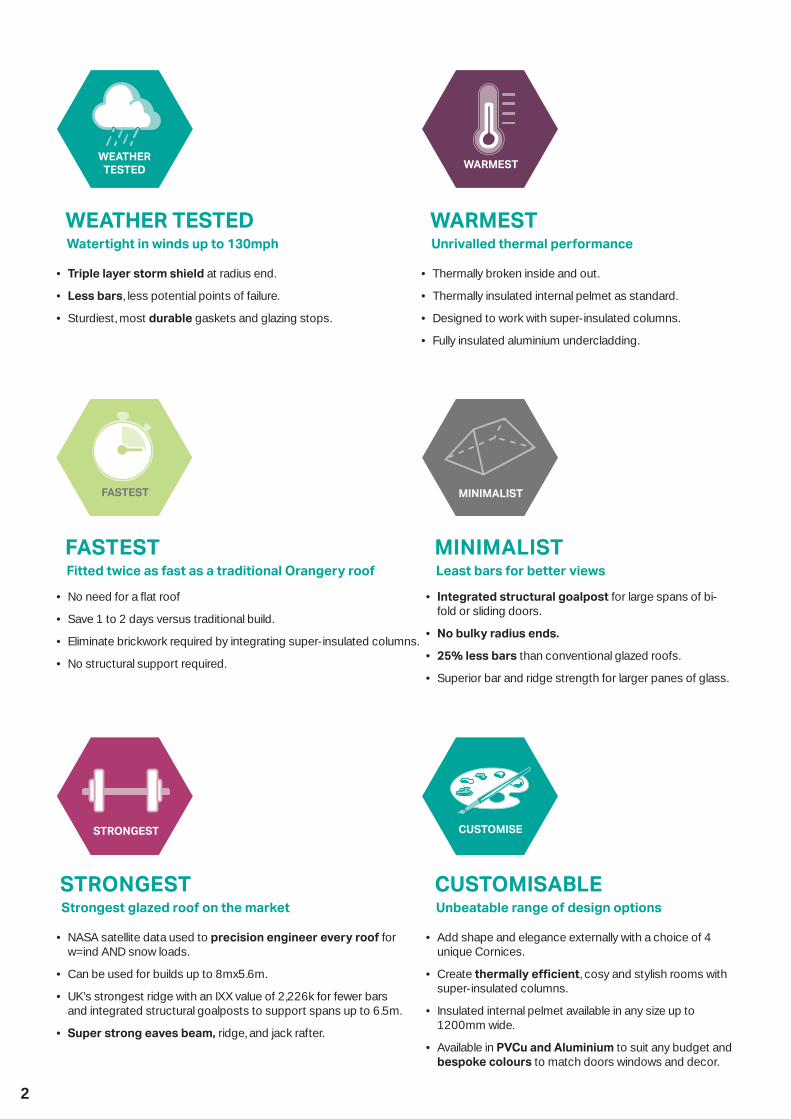
FASTEST Fitted twice as fast as a traditional Orangery roof
• No need for a fl at roof
• Save 1 to 2 days versus traditional build.
• Eliminate brickwork required by integrating super-insulated columns.
• No structural support required.
MINIMALIST Least bars for better views
• Integrated structural goalpost for large spans of bi-fold or sliding doors.
• No bulky radius ends.
• 25% less bars than conventional glazed roofs.
• Superior bar and ridge strength for larger panes of glass.
CUSTOMISABLE Unbeatable range of design options
• Add shape and elegance externally with a choice of 4 unique Cornices.
• Create thermally effi cient, cosy and stylish rooms with super-insulated columns.
• Insulated internal pelmet available in any size up to 1200mm wide.
• Available in PVCu and Aluminium to suit any budget and bespoke colours to match doors windows and decor.
STRONGESTStrongest glazed roof on the market
• NASA satellite data used to precision engineer every roof for w=ind AND snow loads.
• Can be used for builds up to 8mx5.6m.
• UK’s strongest ridge with an IXX value of 2,226k for fewer bars and integrated structural goalposts to support spans up to 6.5m.
• Super strong eaves beam, ridge, and jack rafter.
WARMEST Unrivalled thermal performance
• Thermally broken inside and out.
• Thermally insulated internal pelmet as standard.
• Designed to work with super-insulated columns.
• Fully insulated aluminium undercladding.
WEATHER TESTED Watertight in winds up to 130mph
• Triple layer storm shield at radius end.
• Less bars, less potential points of failure.
• Sturdiest, most durable gaskets and glazing stops.

3
Thank you for choosing the Ultrasky Roof product. This guide is designed to make fitting as straightforward as possible.
Before you commence installation of the roof, please;
1) Take a moment to read these two introductory
pages before reading the rest of this guide.
2) Do not fix the frames down at this stage – only
temporarily ‘pin’ the frames to the house wall (one
fixing each side) to allow the conservatory to ‘float’.
Any feedback - positive or negative - is welcomed so
we can make our systems even better.
Please contact the Ultraframe Tech Support Team
on 01200 452 918 or email [email protected]
3
2
4
6
8
5
7
1
9
10
11
ULTRASKY ROOF1 High performance thermal break 2 Patented thermally insulated aluminium rafter3 Super strong ridge for fewer bars and more light4 Thermally isolating top cap clip5 ‘Secure- t’ end caps are a further thermal barrier6 Patented insulated perimeter ceiling (max. 1200mm wide)7 Housing for additional insulation, speakers or down lights8 Decorative cornice to hide gutters and add shape to the roo ine9 ‘Heat guard’ modesty shield 10 Adjustable reinforced stopper to prevent glass slipping11 Choice of aluminium or PVCu internal and externals
FEWER BARS
4xSTRONGER
MORE LIGHT GUARANTEEYEAR
ULTRASKY ROOF COMBINES FRESH MODERN STYLING WITH NATURAL LIGHT TO CREATE A BEAUTIFUL WARM GLAZED EXTENSION WITH THE STYLE AND GRANDEUR OF A TRADITIONAL ORANGERY
Ultrasky’s Stormshield Protection System includes:
1 Waterproof glazing compression trims2 Ridge end weathering shields3 Secure t radius end covers
STRENGTH, WARMTH AND MAXIMUM LIGHT,PERFORMANCE ENGINEERING
3
2
1
PROTECTION
stormSHIELD
SYSTEM
“Fully thermally broken roofi ng system inside and out”

4
General pointsCare should be taken when handling components that are seen by the homeowner, as surfaces may be scratched if not handled with care. Choose a suitable area for unpacking the components and always check them before tting. Any claims for missing or damaged parts are only accepted in line with our standard terms and conditions of sale. Health & safetySite safety is paramount. The Construction (Design & Management) Regulations 2015 apply to the whole construction process, on all construction projects from concept through to completion. Compliance is required to ensure construction projects are carried out in a way that secures health and safety. The installation company shall be responsible for the safety of all of the tting team, the customer and members of the public.
The Surveyor should have carried out a risk assessment to reduce risk on site and this should have been discussed with you prior to starting.
Please use safe working platforms and ladders that comply with BS EN 131. Always use equipment in line with manufacturers recommendations. Personal Protective Equipment –such as goggles, mask and ear defenders – should be used when, for example, grinding out for the ashing.
Careful consideration should be given to the safe disposal of all packaging – our packaging is predominantly made from recycled materials and can be readily recycled.
ProductThe roof kit is supplied with a location plan, a quality control check list for the box in which this guide arrives and, of course, this installation guide. The location plan is used to match individual components to their respective position on the roof. Our numbering convention always
starts at the top left, against the house wall as you look from outside the conservatory back at the host wall.
The majority of aluminium and PVCu components contain identi cation codes, usually by inkjetting or labelling – should you need to re-order a part this should help. Please ask for a copy of our Classic product guide to keep in the van, which will give you further assistance with future identi cation.
SealingIt is important to use the correct sealant when sealing the roof.1. For roofs glazed with Polycarbonate (or standard sealed units) a low modulus neutral cure brand of silicone must be used.2. For roofs glazed with Conservaglass or other true `self cleaning` glass, then MS Polymer sealant such as Rotabond 2000 must be used.
Sealed UnitsAll protective handling tape must be removed prior to installation. For the correct selection of sealant please see above
The SuperstructureCheck the dwarf wall or plinth for being level all round. Ensure that all frames which abut the host wall are vertically plumb, which will then allow perfect alignment with our Classic eavesbeam. Before starting to install the roof, please check the condition of the host wall and whether it’s plumb – depending upon what you nd, these conditions can seriously a ect the nal integrity of the roof, particularly when a Tie Bar Replacement Kit (TBRK) is tted.
Technical SupportTel: 01200 452 918Email: [email protected]
CONTENTS
PRE INSTALLATION CHECKS 5TOOLS REQUIRED 5HANDLING ALUMINIUM PRODUCTS 6CLEANING AND MAINTENANCE ALUMINIUM EXTERNAL 6GENERAL INSTALLATION 7 17FITTING STARTER BARS WITH ALUMINIUM INTERNAL CLADDING IF SPECIFIED 8FITTING ALUMINIUM INTERNAL CLADDING HIPS 9 FITTING JACK RAFTERS 10FITTING ALUMINIUM INTERNAL CLADDING TRANSOMS 10 11 ADDITIONAL STEPS WHEN CORNICE IS USED WITH LOGGIA COLUMNS 11CORNICE AND GUTTER 12
GLASS INSTALLATION MUNTIN BAR 13INTERNAL PELMET 14 15TIE BAR STRUT BEAM 15 16CORNICE INSTALLATION 18TIE BAR REPLACEMENT KIT TBRK 18PVCU ROOF VENT INSTALLATION SASH 19 20ALUMINIUM ROOF VENT INSTALLATION 20 21VENT MOTOR 21 22SUPER DUTY EAVES BEAM 22BOX GUTTER INSTALLATION 23 24BOX GUTTER JOINTING 24BOX GUTTER SUPPORT 25RAISED BACK BOX GUTTERS 25 26
5
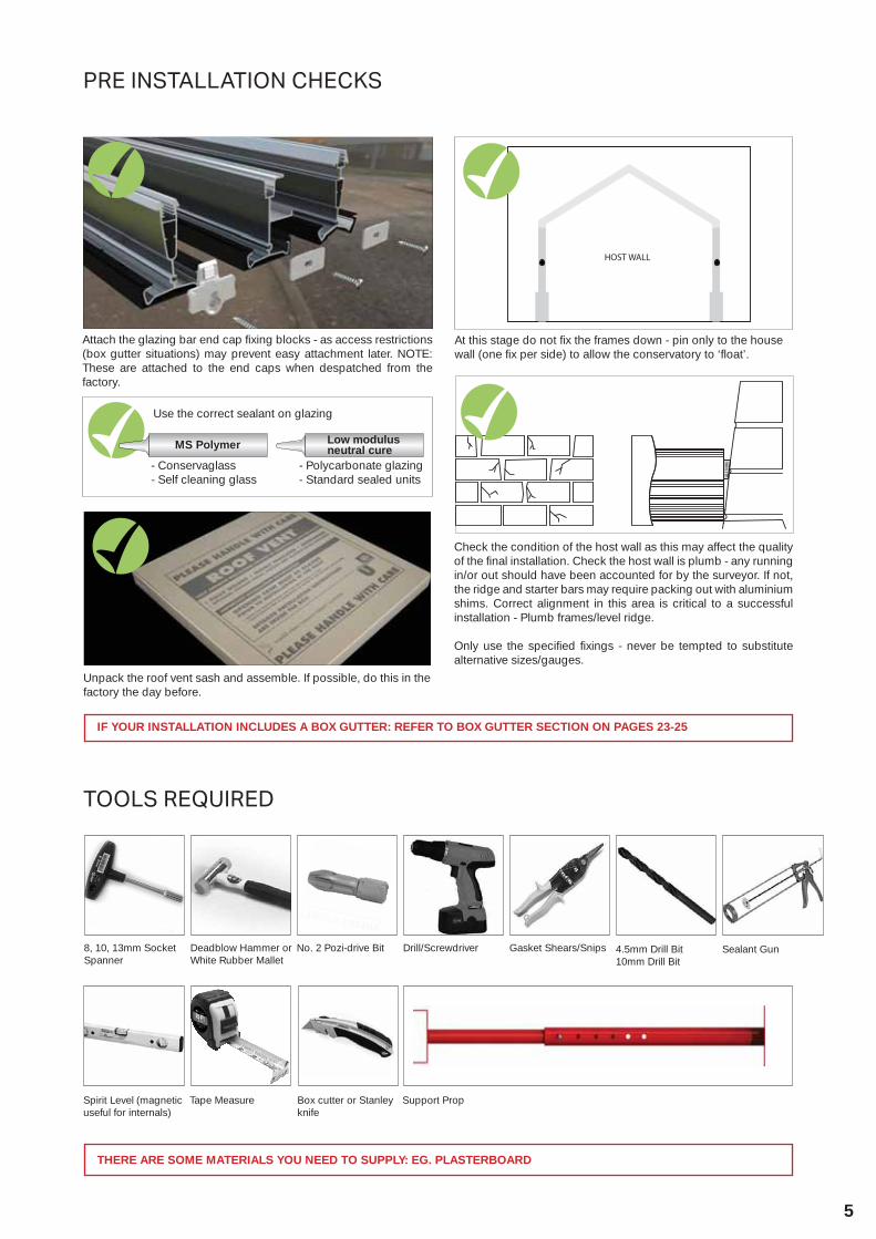
TOOLS REQUIRED
THERE ARE SOME MATERIALS YOU NEED TO SUPPLY: EG. PLASTERBOARD
8, 10, 13mm Socket Spanner
Deadblow Hammer or White Rubber Mallet
No. 2 Pozi-drive Bit Drill/Screwdriver Gasket Shears/Snips 4.5mm Drill Bit10mm Drill Bit
Sealant Gun
Spirit Level (magnetic useful for internals)
Tape Measure Box cutter or Stanley knife
Support Prop
Attach the glazing bar end cap fixing blocks - as access restrictions (box gutter situations) may prevent easy attachment later. NOTE: These are attached to the end caps when despatched from the factory.
Check the condition of the host wall as this may affect the quality of the final installation. Check the host wall is plumb - any running in/or out should have been accounted for by the surveyor. If not, the ridge and starter bars may require packing out with aluminium shims. Correct alignment in this area is critical to a successful installation - Plumb frames/level ridge.
Only use the specified fixings - never be tempted to substitute alternative sizes/gauges.
At this stage do not fix the frames down - pin only to the house wall (one fix per side) to allow the conservatory to ‘float’.
Unpack the roof vent sash and assemble. If possible, do this in the factory the day before.
Use the correct sealant on glazing
Low modulus neutral cure
- Polycarbonate glazing- Standard sealed units
MS Polymer
- Conservaglass- Self cleaning glass
PRE INSTALLATION CHECKS
IF YOUR INSTALLATION INCLUDES A BOX GUTTER: REFER TO BOX GUTTER SECTION ON PAGES 23-25

6
QUALITY EXPECTATIONS ON INSTALLATION.Appearance: This is assessed based on the selection of the ‘significant’ (primary) surface. From a distance of 3m, stand at an oblique angle of 60degree and then defects such as blisters, runs, pin holes etc should NOT be seen. Colour and gloss: Viewed from 5m, the coating must be of even colour and gloss with good coverage.
PAINTED ALUMINIUM PRODUCTS - PLEASE NOTEAll paints will ‘chalk’ to some extent and there will be a reduction in gloss level over time. (See Cleaning and Maintenance guidelines on the back cover)
Grease marks, dirt and mastic spillage may be removed using soapy water.
If storing in warehouse racking or on frails/roof racks, take care to support the products and do not over tension straps and ropes. When opening sealed packs, use a special box knife opener.
HANDLING ALUMINIUM PRODUCTS
Take care when tting aluminium products to not use excessive force.
1 2 3
CAUTION WHEN HANDLING ALUMINIUM PRODUCTS USE PROTECTIVE HAND WEAR.
If surface damage is encountered, use 120-360 grit paper to prepare the surface. Wipe clean with white spirit.
1
Finally, apply an air drying top coat with a ne brush.
3
Ensure the surface is dry – apply a thin primer coat using a ne brush.
2
General cleaning can be undertaken by a wash with warm soapy water.
4
For added protection, a wax polish can be applied up to twice per year – follow the polish manufacturer’s instructions carefully.
5
CLEANING AND MAINTENANCE ALUMINIUM EXTERNAL
It should be noted that polyester powder coatings are not maintenance free – the extent of cleaning depends upon the local environment and on the attitude of the building owner. Think cars here...if the building owner wants a nish like that, more regular cleaning is needed. All paints will ‘chalk’ to some extent and there will be a reduction in gloss level over time – this can be restored.
PLEASE PASS TO HOMEOWNER
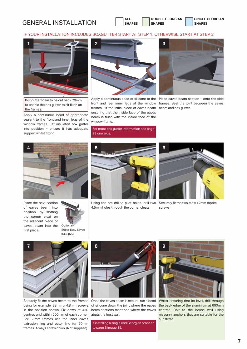
DOUBLE GEORGIAN SHAPES
SINGLE GEORGIAN SHAPES
ALL SHAPES
7
GENERAL INSTALLATION
1
Place eaves beam section – onto the side frames. Seal the joint between the eaves beam and box gutter.
3
Apply a continuous bead of silicone to the front and rear inner legs of the window frames. Fit the initial piece of eaves beam ensuring that the inside face of the eaves beam is ush with the inside face of the window frame.
2
Securely t the eaves beam to the frames using for example, 38mm x 4.8mm screws in the position shown. Fix down at 450 centres and within 200mm of each corner. For 60mm frames use the inner eaves extrusion line and outer line for 70mm frames. Always screw down. (Not supplied)
7
Whilst ensuring that its level, drill through the back edge of the aluminium at 600mm centres. Bolt to the house wall using masonry anchors that are suitable for the substrate.
8
Place the next section of eaves beam into position, by slotting the corner cleat on the adjacent piece of eaves beam into the rst piece.
4
Securely t the two M5 x 12mm taptite screws.
6
Using the pre-drilled pilot holes, drill two 4.5mm holes through the corner cleats.
5
Once the eaves beam is secure, run a bead of silicone down the joint where the eaves beam sections meet and where the eaves abuts the host wall.
9
Apply a continuous bead of appropriate sealant to the front and inner legs of the window frames. Lift insulated box gutter into position – ensure it has adequate support whilst tting.
Box gutter foam to be cut back 70mm to enable the box gutter to sit ush on the frames.
IF YOUR INSTALLATION INCLUDES BOXGUTTER START AT STEP 1, OTHERWISE START AT STEP 2
Optional Super Duty Eaves (SEE p22)
If installing a single end Georgian proceed to page 8 image 15.
For more box gutter information see page 23 onwards.

DOUBLE GEORGIAN SHAPES
SINGLE GEORGIAN SHAPES
ALL SHAPES
8
GENERAL INSTALLATION
Either peel back or knife o a small amount of the insulation where the cleat is to be xed. Drill a 4.5mm pilot hole and then x
the cleats with the two M5 12mm taptite screws provided.. The protruding taptite screws will need trimming back prior to xing the adaptor (alternatively, when its
time to insert the adaptor, undo the taptites, drill a pilot hole through the adaptor and then re-screw the taptites and fully seal).
10
Now seal the internal joint between the eaves beam and box gutter and back point the leading edge of the box gutter where it sits on the side frames.
12
Mark out and grind a channel in the masonry for the ashing – blow out any dust in the channel.
11
Attach spring clips (LAN014) to side of glazing bar - to each side of bar - 50mm from top of transom bar - 100 mm from eaves (both hip and transom). Push the leg in under the gasket and spring around the underside as shown. Ensure the clips are fully pushed on.
1
Fit the pre formed soaker trim to each starter bar, tighten the bars at the ridge and then at the eaves. Ensure the bar caps have been tted.
2
Prop ridge in position using suitable supports, centralising between eaves beam sections. (When the ridge features aluminium painted internal nish it will need to be protected whilst supporting).
14
Using the roof rise height supplied set the ridge and x the bracket to the host wall using the appropriate xings.
15
Spring clips in position.
3
FITTING STARTER BARS WITH ALUMINIUM INTERNAL CLADDING IF SPECIFIED NOTE: IF FITTING STARTER BARS ENSURE CLIPS ARE INSTALLED FIRST LAN014
LANRF001 is supplied pre-installed into the ridge. Remove and fix radius end (LAN032BL) then replace the screw. If using 3 bar attach LAN031 using EBT001. (M5x12 P021 pan screw).
13
LAN031 EBT001
9
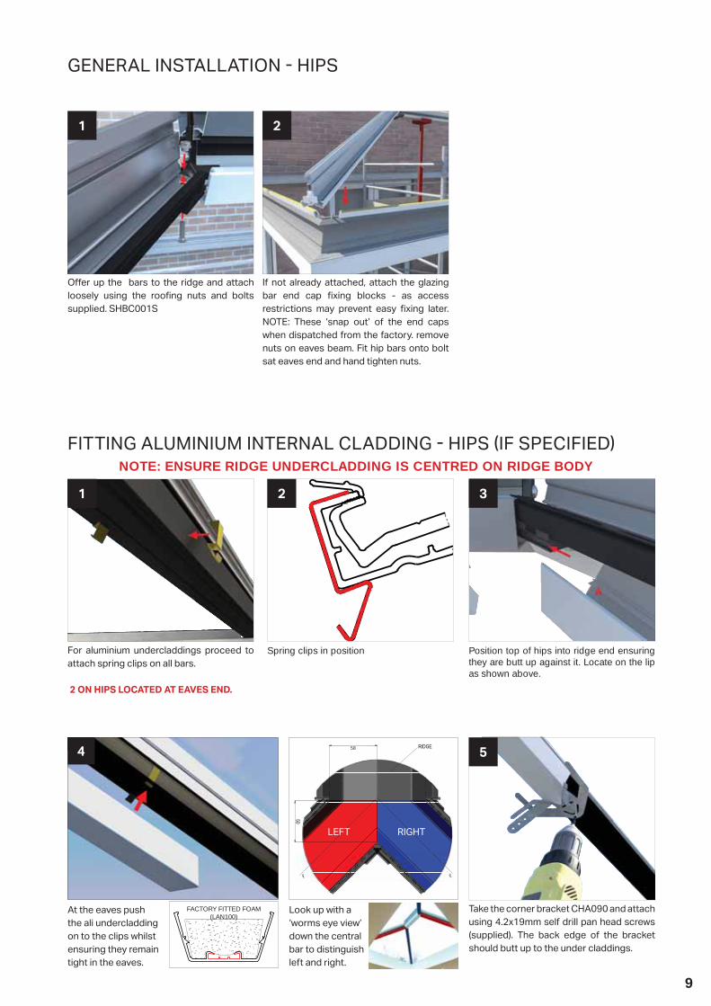
GENERAL INSTALLATION HIPS
O er up the bars to the ridge and attach loosely using the roo ng nuts and bolts supplied. SHBC001S
1
If not already attached, attach the glazing bar end cap xing blocks - as access restrictions may prevent easy xing later. NOTE: These ‘snap out’ of the end caps when dispatched from the factory. remove nuts on eaves beam. Fit hip bars onto bolt sat eaves end and hand tighten nuts.
2
FITTING ALUMINIUM INTERNAL CLADDING HIPS IF SPECIFIEDNOTE: ENSURE RIDGE UNDERCLADDING IS CENTRED ON RIDGE BODY
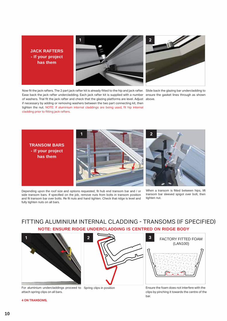
For aluminium undercladdings proceed to attach spring clips on all bars.
2 ON HIPS LOCATED AT EAVES END.
1
Position top of hips into ridge end ensuring they are butt up against it. Locate on the lip as shown above.
3
Spring clips in position
2
RIDGE
CLCL
4
At the eaves push the ali undercladding on to the clips whilst ensuring they remain tight in the eaves.
Take the corner bracket CHA090 and attach using 4.2x19mm self drill pan head screws (supplied). The back edge of the bracket should butt up to the under claddings.
5
FACTORY FITTED FOAM (LAN100)
Look up with a ‘worms eye view’ down the central bar to distinguish left and right.
RIGHTLEFT
58
10
Depending upon the roof size and options requested, fit hub end transom bar and / or side transom bars. If specified on the job, remove nuts from bolts in transom position and fit transom bar over bolts. Re fit nuts and hand tighten. Check that ridge is level and fully tighten nuts on all bars.
1
1
Now t the jack rafters. The 2 part jack rafter kit is already tted to the hip and jack rafter. Ease back the jack rafter undercladding. Each jack rafter kit is supplied with a number of washers. Trial t the jack rafter and check that the glazing platforms are level. Adjust if necessary by adding or removing washers between the two part connecting kit, then tighten the nut. NOTE: If aluminium internal claddings are being used, t hip internal cladding prior to tting jack rafters.
Slide back the glazing bar undercladding to ensure the gasket lines through as shown above.
2
JACK RAFTERS - If your project
has them
2
When a transom is fitted between hips, lift transom bar sleeved spigot over bolt, then tighten nut.
TRANSOM BARS- If your project
has them
FITTING ALUMINIUM INTERNAL CLADDING TRANSOMS IF SPECIFIEDNOTE: ENSURE RIDGE UNDERCLADDING IS CENTRED ON RIDGE BODY
For aluminium undercladdings proceed to attach spring clips on all bars.
4 ON TRANSOMS,
1
Spring clips in position
2 FACTORY FITTED FOAM (LAN100)
3
Ensure the foam does not interfere with the clips by pinching it towards the centre of the bar.
11
2a
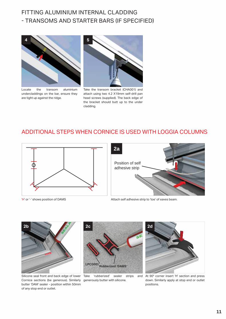
‘H’ or ‘-’ shows position of DAMS Attach self adhesive strip to ‘toe’ of eaves beam.
Position of selfadhesive strip
ADDITIONAL STEPS WHEN CORNICE IS USED WITH LOGGIA COLUMNS
LPCD090
Silicone seal front and back edge of lower Cornice sections (be generous). Similarly butter ‘DAM’ sealer - position within 50mm of any stop end or outlet.
2b
At 90° corner insert ‘H’ section and press down. Similarly apply at stop end or outlet positions.
2d
Take ‘rubberized’ sealer strips and generously butter with silicone.
2c
Rubberized ‘DAMS’LPCD001
FITTING ALUMINIUM INTERNAL CLADDING TRANSOMS AND STARTER BARS IF SPECIFIED
Locate the transom aluminium undercladdings on the bar, ensure they are tight up against the ridge.
4
Take the transom bracket (CHA001) and attach using two 4.2 X19mm self-drill pan head screws (supplied). The back edge of the bracket should butt up to the under cladding.
5

12
Fit the cleats (CRN001) to the desired side using the xings provided (CRN006) as shown and assemble the remaining lower sections.
2
Fit all the gutter brackets supplied with the kit at maximum 750mm centres and maximum 200mm from each corner.
4
Secure each corner using the cleats (CRN001) and xings provided (CRN006).
The gutter should now be tted check integrity of all gutter joints before proceeding further.
3
GENERAL INSTALLATION CORNICE AND GUTTER
Gutter bracket shown fully engaged.
8
Locate the back edge of each section of gutter into the slot in the gutter bracket.
7
Decide the position of the gutter outlet by lining the extrusion ‘v’ groove up with the centre of the hole for the down pipe. Using a 73mm dia hole saw, cut the hole for the down pipe in the lower section.
1
‘V’ gro
ove
5 6
Next, build on the ground the gutter runs, by rolling items like a stopend under the back edge of a gutter jointer. Push up to the insertion line. DO NOT silicone seal, this would prevent natural expansion contraction.
Snap the integral clips on the adaptors over the gutter. IMPORTANT: ensure all lengths of gutter t to the market insertion line seen in all unions and box gutter adaptors.
13
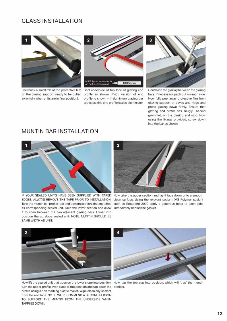
IF YOUR SEALED UNITS HAVE BEEN SUPPLIED WITH TAPED EDGES, ALWAYS REMOVE THE TAPE PRIOR TO INSTALLATION.Take the muntin bar pro le (top and bottom section) that matches its corresponding sealed unit. Take the lower section and allow it to span between the two adjacent glazing bars. Lower into position the up slope sealed unit. NOTE: MUNTIN SHOULD BE SAME WIDTH AS UNIT.
1
Now take the upper section and lay it face down onto a smooth clean surface. Using the relevant sealant (MS Polymer sealant such as Rotabond 2000 apply a generous bead to each side, immediately behind the gasket.
2
MUNTIN BAR INSTALLATION
Now lift the sealed unit that goes on the lower slope into position, turn the upper pro le over, place it into position and tap down the pro le using a non marking plastic mallet. Wipe clean any sealant from the unit face. NOTE: WE RECOMMEND A SECOND PERSON TO SUPPORT THE MUNTIN FROM THE UNDERSIDE WHEN TAPPING DOWN.
3
Now, tap the top cap into position, which will ‘trap’ the muntin pro les.
4
Peel back a small tab of the protective lm on the glazing support (ready to be pulled away fully when units are in nal position).
1
Centralise the glazing between the glazing bars. If necessary, pack out on each side. Now fully peel away protective lm from glazing support at eaves and ridge and press glazing down rmly. Ensure that glazing end pro le sits snugly behind grommet, on the glazing end stop. Now using the xings provided, screw down into the bar as shown.
2
Seal underside of top face of glazing end pro le as shown (PVCu version of end pro le is shown - if aluminium glazing bar top caps, this end pro le is also aluminium).
3
MS Polymer sealant only on Self cleaning glass MS Polymer
GLASS INSTALLATION
14
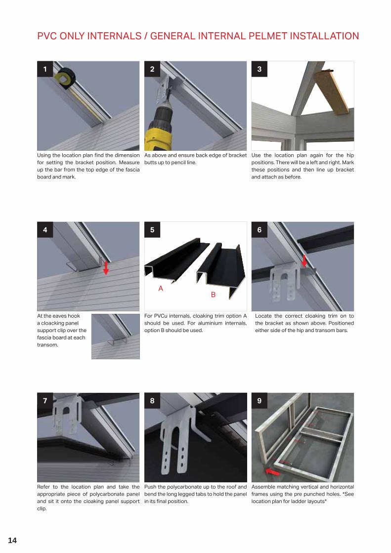
At the eaves hook a cloacking panel support clip over the fascia board at each transom.
4 5
Using the location plan nd the dimension for setting the bracket position. Measure up the bar from the top edge of the fascia board and mark.
1
Use the location plan again for the hip positions. There will be a left and right. Mark these positions and then line up bracket and attach as before.
3
As above and ensure back edge of bracket butts up to pencil line.
2
For PVCu internals, cloaking trim option A should be used. For aluminium internals, option B should be used.
6
AB
Locate the correct cloaking trim on to the bracket as shown above. Positioned either side of the hip and transom bars.
Refer to the location plan and take the appropriate piece of polycarbonate panel and sit it onto the cloaking panel support clip.
7
Assemble matching vertical and horizontal frames using the pre punched holes. *See location plan for ladder layouts*
9
Push the polycarbonate up to the roof and bend the long legged tabs to hold the panel in its nal position.
8
PVC ONLY INTERNALS GENERAL INTERNAL PELMET INSTALLATION

15
INTERNAL PELMET CONTINUED
Attach L-Shaped frame using one of the three positions on the bracket, use 4 x13 self-drill screws provided.
10
Check the frame is level and x either on or below fascia using 4.8 x 32 self-drill screws provided.
11
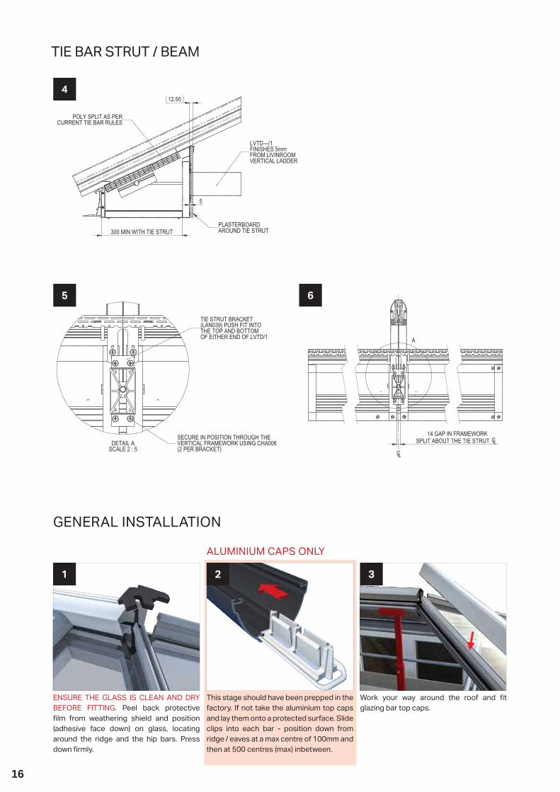
TIE BAR STRUT BEAM
Overview
1
Attach the threaded bar through the barrel and then t washer and two M10 nuts. Next insert the barrel assembly into the slot in the underside of the glazing bar and secure with a further two M10 nuts.
2
Now insert the PVCU tube (this acts as a damper) over the threaded bar and secure in place with double sided tape or silicone. Now insert the box section beam over the threaded bar/tube assembly.
3
LAN039 (x2)
LVTD/1
CHA006 (x4)
FIT THE 2 LAN039 BRACKETSINTO THE TOP AND BOTTOM
OF THE LVTD/1
SECURE TO LIVINROOM FRAMEWORKWITH 4 CHA006 SCREWS
16
GENERAL INSTALLATION
ENSURE THE GLASS IS CLEAN AND DRY BEFORE FITTING. Peel back protective lm from weathering shield and position
(adhesive face down) on glass, locating around the ridge and the hip bars. Press down rmly.
1
Work your way around the roof and t glazing bar top caps.
3
This stage should have been prepped in the factory. If not take the aluminium top caps and lay them onto a protected surface. Slide clips into each bar - position down from ridge / eaves at a max centre of 100mm and then at 500 centres (max) inbetween.
2
ALUMINIUM CAPS ONLY
TIE BAR STRUT BEAM
4
5 6
300 MIN WITH TIE STRUT
12.50
5
LVTD---/1FINISHES 5mmFROM LIVINROOMVERTICAL LADDER
PLASTERBOARDAROUND TIE STRUT
POLY SPLIT AS PERCURRENT TIE BAR RULES
14 GAP IN FRAMEWORKSPLIT ABOUT THE TIE STRUT CL
A
CL
DETAIL ASCALE 2 : 5
TIE STRUT BRACKET(LAN039) PUSH FIT INTOTHE TOP AND BOTTOM OF EITHER END OF LVTD/1
SECURE IN POSITION THROUGH THEVERTICAL FRAMEWORK USING CHA006(2 PER BRACKET)
17
GENERAL INSTALLATION
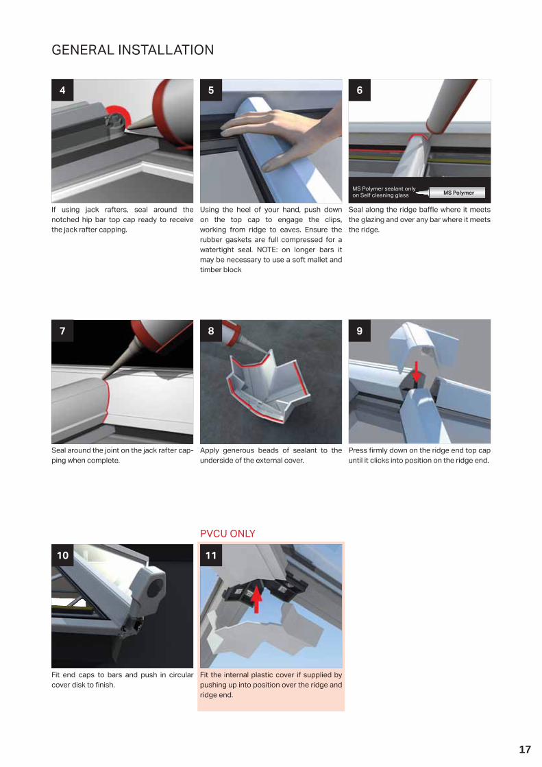
Seal around the joint on the jack rafter cap-ping when complete.
7
Press rmly down on the ridge end top cap until it clicks into position on the ridge end.
8
Apply generous beads of sealant to the underside of the external cover.
9
PVCU ONLY
Fit end caps to bars and push in circular cover disk to nish.
10
Fit the internal plastic cover if supplied by pushing up into position over the ridge and ridge end.
11
If using jack rafters, seal around the notched hip bar top cap ready to receive the jack rafter capping.
4
Seal along the ridge ba e where it meets the glazing and over any bar where it meets the ridge.
6
Using the heel of your hand, push down on the top cap to engage the clips, working from ridge to eaves. Ensure the rubber gaskets are full compressed for a watertight seal. NOTE: on longer bars it may be necessary to use a soft mallet and timber block
5
MS Polymer sealant only on Self cleaning glass MS Polymer

18
INSTALLATION - ALUMINIUM INTERNAL COVER (OPTIONAL ITEM)
1
Clip fit into position the aluminium internal radius end cover trim.
2 3
Clipped into final position. No central leg when roof has central transom between hip bars fitted.
CORNICE INSTALLATION CONTINUED FROM PAGE 12
Where the eaves beam sits against the host masonry wall, it has a structural moulding attached to the eaves beam. This has three xing positions cast into it to allow attachment into masonry –
choose the hole that directly lines up with solid masonry and drill a 10mm hole into the host wall. Attach the structural moulding using the M8x80mm anchor supplied. Silicone seal the gap where the moulding attaches to the eaves beam.
1
Place the inline strap (SES005, 165mm / SES006, 265mm) over the single roo ng bolt on the sloped gutter. Temporarily x the bracket to the host wall using three M8 sleeve anchor bolts (SAB001) supplied. Fit the starter bar. Secure the strap to the eaves with the two xings supplied (UZBGF001-D). Finally, x anchor bolts.
90° EAVES AND RAISED BACK BOX GUTTER ASSEMBLY
2
REFER TO THE CORNICE INSTALLATION GUIDE TO COMPLETE CURVED, 1, 2 AND 3 TIER VARIANTS
3
Fit cleats as shown.O er up the middle Cornice section into position, (it may be advisable to temporarily support the lower Cornice section whilst xing) secure using xings provided
(CRN007). (Long reach driver required).
Ensure the eaves beam, glazing bars, ridge/wallplate are already installed
Prior to tting gutter o er up the lower Cornice section then secure into position using the xings provided (CRN007). Please note: Always start with the front facet!
1
Min 120mm
from co
rner
TIE BAR REPLACEMENT KIT TBRK

19
Remove all handling tape around the perimeter of the unit. When inserting the glazing ensure it is the correct way round and the external face is face down onto the continuous bead of sealant.
1
Remove the opening vent sash from the vent mainframe and lay the opening sash upside down on a at surface. (Protect the surface to prevent damage to the sash). Run a continuous bead of appropriate sealant immediately behind the black co-extruded gasket, taking care to ensure a continuous run around the perimeter of the opening sash.
2
Seal the area around the full perimeter of the glazing.
1
Centrally screw x the sash bracket into the position shown above using the xings pro-vided. Leave the sash to cure before tting.
3
Re- t the ‘L’ shaped serrated glazing beads to the opening sash. A small block of timber is useful to carefully knock in the beads.
2
With the opening sash removed, lay the mainframe upside down on a smooth clean surface (protect the surface to prevent damage). Run a continuous bead of sealant (appropriate to the glass type) immediately behind the co-extruded gasket on the upper and lower legs.
4
Lift the lower mainframe leg and o er into position the lower double glazed unit. Press down the mainframe rmly into position.
6
Carefully lower the frame into position on to the upper double glazed unit, making sure that any glazing tape has been removed from the edges of the sealed unit).
5
MS Polymer sealant only on Self cleaning glass MS Polymer
MS Polymer sealant only on Self cleaning glass MS Polymer
IMPORTANTThe roof vent opening sash must be glazed prior to fi tting the vent to the conservatory roof. Leaving the recommended time (dependent on outside air temperature) for the sealant to cure.Sealant curing time will vary depending upon the time of year and outside temperature prevailing, this could take up to 8 hours in cold conditions. This is critical when the sash is to be glazed with a sealed unit.
PVC ROOF VENT INSTALLATION SASH
PVC ROOF VENT INSTALLATION SASH CONTINUED
20
PVC ROOF VENT INSTALLATION
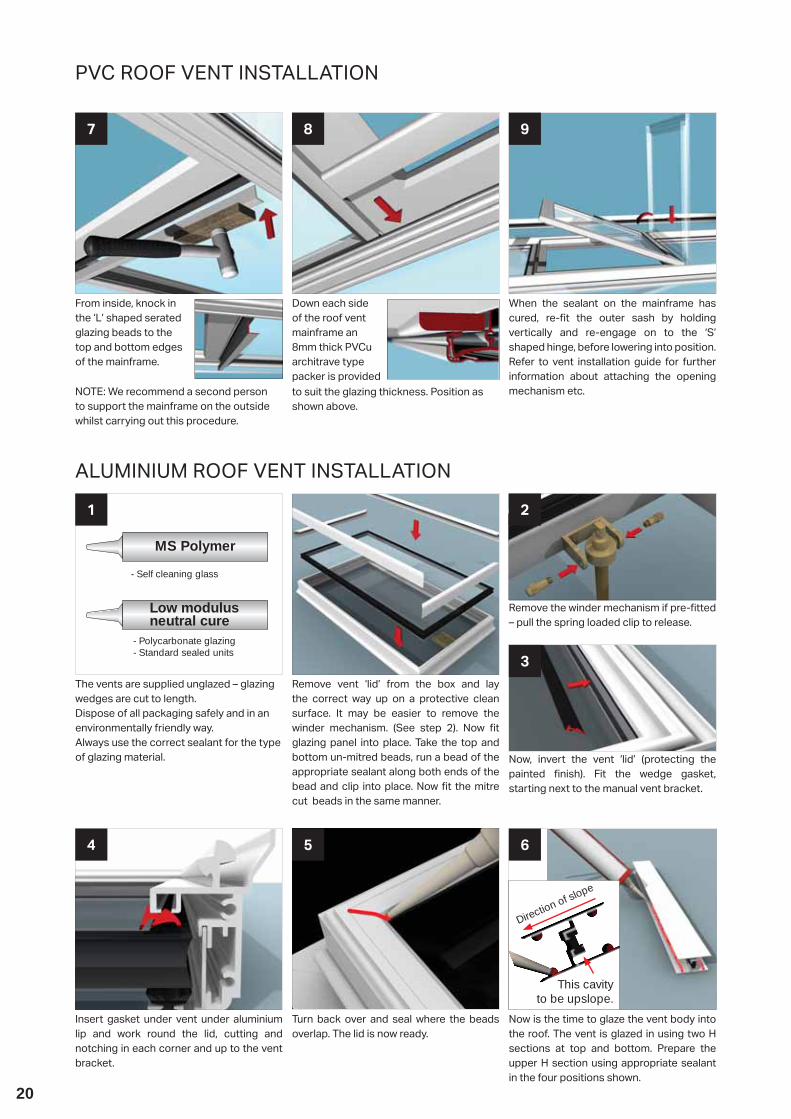
From inside, knock in the ‘L’ shaped serated glazing beads to the top and bottom edges of the mainframe.
7
When the sealant on the mainframe has cured, re- t the outer sash by holding vertically and re-engage on to the ‘S’ shaped hinge, before lowering into position. Refer to vent installation guide for further information about attaching the opening mechanism etc.
8
Down each side of the roof vent mainframe an 8mm thick PVCu architrave type packer is provided
9
to suit the glazing thickness. Position as shown above.
NOTE: We recommend a second person to support the mainframe on the outside whilst carrying out this procedure.
Insert gasket under vent under aluminium lip and work round the lid, cutting and notching in each corner and up to the vent bracket.
4
Now is the time to glaze the vent body into the roof. The vent is glazed in using two H sections at top and bottom. Prepare the upper H section using appropriate sealant in the four positions shown.
6
Turn back over and seal where the beads overlap. The lid is now ready.
5
ALUMINIUM ROOF VENT INSTALLATION
12b2a
The vents are supplied unglazed – glazing wedges are cut to length.Dispose of all packaging safely and in an environmentally friendly way.Always use the correct sealant for the type of glazing material.
Remove the winder mechanism if pre- tted – pull the spring loaded clip to release.
Remove vent ‘lid’ from the box and lay the correct way up on a protective clean surface. It may be easier to remove the winder mechanism. (See step 2). Now t glazing panel into place. Take the top and bottom un-mitred beads, run a bead of the appropriate sealant along both ends of the bead and clip into place. Now t the mitre cut beads in the same manner.
Now, invert the vent ‘lid’ (protecting the painted nish). Fit the wedge gasket, starting next to the manual vent bracket.
3
Low modulus neutral cure
- Polycarbonate glazing- Standard sealed units
MS Polymer
- Self cleaning glass
Direction of slope
This cavity to be upslope.
2
21
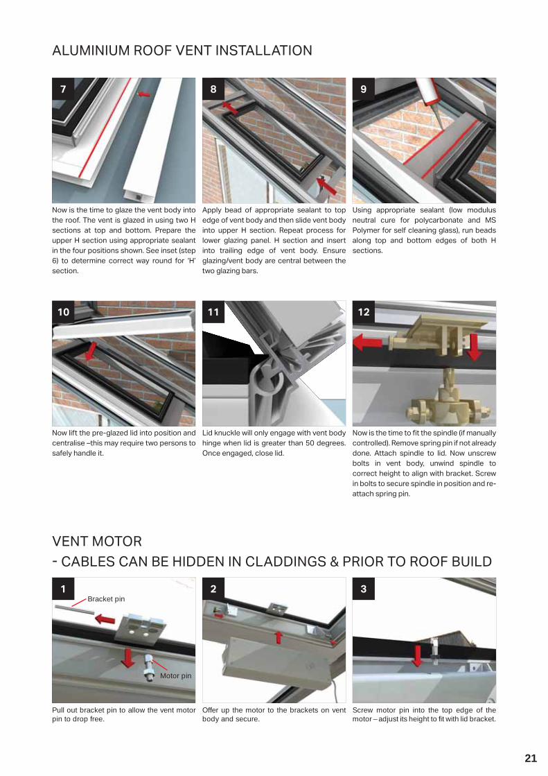
Now is the time to glaze the vent body into the roof. The vent is glazed in using two H sections at top and bottom. Prepare the upper H section using appropriate sealant in the four positions shown. See inset (step 6) to determine correct way round for ‘H’ section.
7
Using appropriate sealant (low modulus neutral cure for polycarbonate and MS Polymer for self cleaning glass), run beads along top and bottom edges of both H sections.
8
Apply bead of appropriate sealant to top edge of vent body and then slide vent body into upper H section. Repeat process for lower glazing panel. H section and insert into trailing edge of vent body. Ensure glazing/vent body are central between the two glazing bars.
9
Now lift the pre-glazed lid into position and centralise –this may require two persons to safely handle it.
10
Now is the time to t the spindle (if manually controlled). Remove spring pin if not already done. Attach spindle to lid. Now unscrew bolts in vent body, unwind spindle to correct height to align with bracket. Screw in bolts to secure spindle in position and re-attach spring pin.
12
Lid knuckle will only engage with vent body hinge when lid is greater than 50 degrees. Once engaged, close lid.
11
Pull out bracket pin to allow the vent motor pin to drop free.
1
Screw motor pin into the top edge of the motor – adjust its height to fit with lid bracket.
3
Offer up the motor to the brackets on vent body and secure.
2
VENT MOTOR CABLES CAN BE HIDDEN IN CLADDINGS & PRIOR TO ROOF BUILD
Bracket pin
Motor pin
ALUMINIUM ROOF VENT INSTALLATION
22
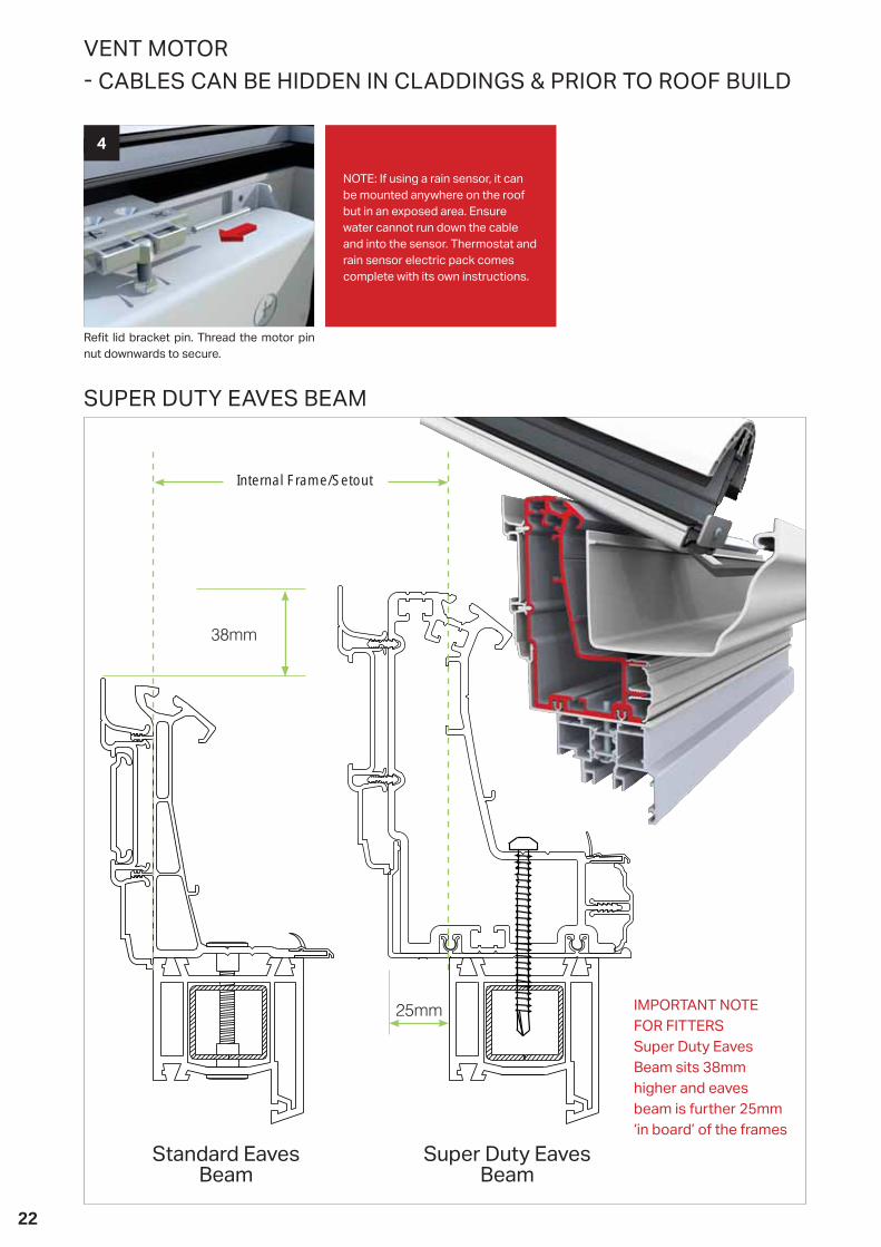
Re t lid bracket pin. Thread the motor pin nut downwards to secure.
4
NOTE: If using a rain sensor, it can be mounted anywhere on the roof but in an exposed area. Ensure water cannot run down the cable and into the sensor. Thermostat and rain sensor electric pack comes complete with its own instructions.
VENT MOTOR CABLES CAN BE HIDDEN IN CLADDINGS & PRIOR TO ROOF BUILD
Standard Eaves Beam
Super Duty Eaves Beam
IMPORTANT NOTE FOR FITTERSSuper Duty Eaves Beam sits 38mm higher and eaves beam is further 25mm ‘in board’ of the frames
Internal Frame/Setout
SUPER DUTY EAVES BEAM
23
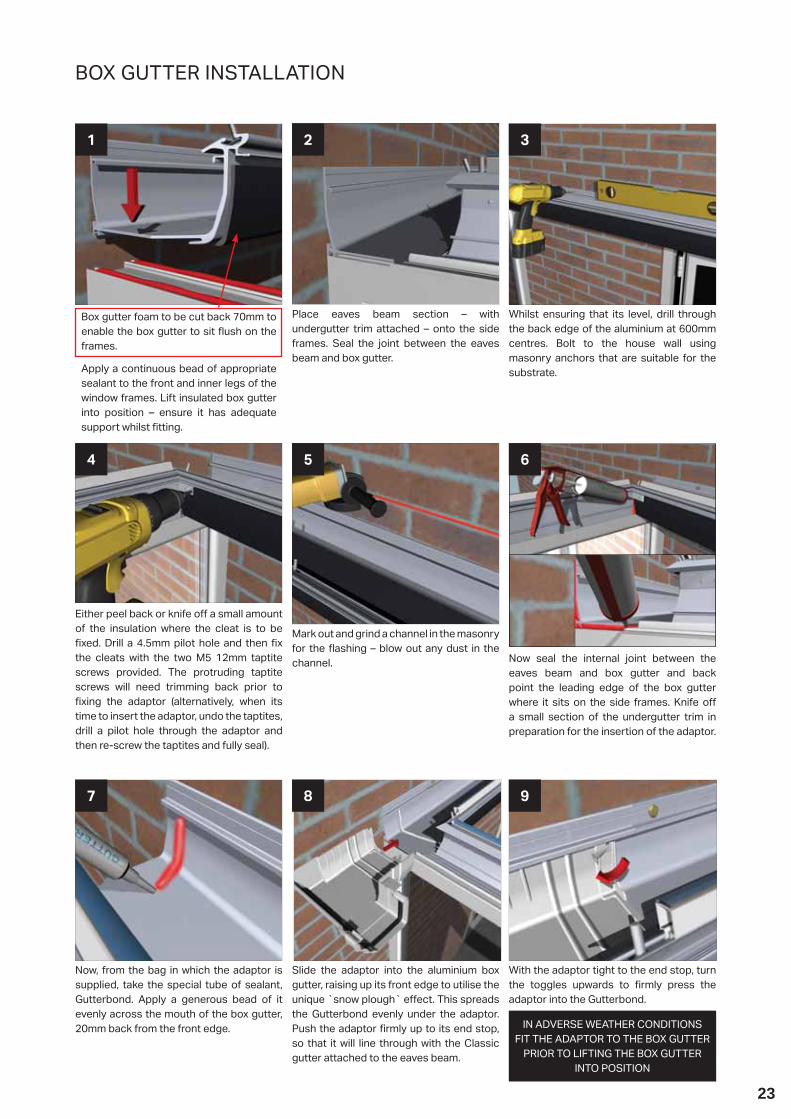
BOX GUTTER INSTALLATION
Box gutter foam to be cut back 70mm to enable the box gutter to sit ush on the frames.
Apply a continuous bead of appropriate sealant to the front and inner legs of the window frames. Lift insulated box gutter into position – ensure it has adequate support whilst tting.
1
Whilst ensuring that its level, drill through the back edge of the aluminium at 600mm centres. Bolt to the house wall using masonry anchors that are suitable for the substrate.
3
Place eaves beam section – with undergutter trim attached – onto the side frames. Seal the joint between the eaves beam and box gutter.
2
Now, from the bag in which the adaptor is supplied, take the special tube of sealant, Gutterbond. Apply a generous bead of it evenly across the mouth of the box gutter, 20mm back from the front edge.
7
With the adaptor tight to the end stop, turn the toggles upwards to rmly press the adaptor into the Gutterbond.
8
Either peel back or knife o a small amount of the insulation where the cleat is to be xed. Drill a 4.5mm pilot hole and then x
the cleats with the two M5 12mm taptite screws provided. The protruding taptite screws will need trimming back prior to xing the adaptor (alternatively, when its
time to insert the adaptor, undo the taptites, drill a pilot hole through the adaptor and then re-screw the taptites and fully seal).
4
Now seal the internal joint between the eaves beam and box gutter and back point the leading edge of the box gutter where it sits on the side frames. Knife o a small section of the undergutter trim in preparation for the insertion of the adaptor.
6
Mark out and grind a channel in the masonry for the ashing – blow out any dust in the channel.
5
Slide the adaptor into the aluminium box gutter, raising up its front edge to utilise the unique `snow plough` e ect. This spreads the Gutterbond evenly under the adaptor. Push the adaptor rmly up to its end stop, so that it will line through with the Classic gutter attached to the eaves beam.
9
IN ADVERSE WEATHER CONDITIONS FIT THE ADAPTOR TO THE BOX GUTTER
PRIOR TO LIFTING THE BOX GUTTER INTO POSITION

24
BOX GUTTER INSTALLATION
Use the balance of the Gutterbond to back point any gaps at the front edge.
10 12
Seal the top and bottom edges of the alu-minium box gutter, where it abuts the house wall.
11
Check surfaces are dry, clean and grease free. De-grease if necessary.Heat both the sealing tape and the box gutter with a heat gun and position the tape over the joint. Press the tape rmly across the joint of the sleeve and the box gutter ensuring there are no air pockets.
4 5
Thoroughly clean the mating parts using wire wool. Surfaces must be clean and grease free. Apply a generous bead of low modulus neutral cure to the pre- xed in-ternal sleeve along the entire face of the sleeve.
1
Drill 6.5mm holes through the box gutter and sleeve (at positions shown, ensuring both halves of the box gutter are ush to-gether) and x using the bolts, nuts and washers provided and in the order shown . Trim any excess o the bolt head before tting the internal cladding as it may foul.
3
Drill through the top edge of the aluminium box gutter at 600mm centres .A xing must be positioned within 50mm each side of the joint.O er second half of the box gutter up to the internal sleeve and push rmly on. Fasten this second box gutter run to the host wall with masonry anchors suitable to the substrate. Ensure both sections are level and ush.
2
Now seal over all the exposed bolt heads, on the inside and outside of the box gutter.
Lastly locate the upper legs of the fascia board on to the box gutter. Finally seal the undercladding against the house wall.
Before lifting into position, assemble the fascia board and undercladding. O er up the undercladding rear legs, and knock up into position.
ALL box gutters (especially those with tie bars or joints) MUST be
supported.
We recommend several types of support for box gutters including brick piers. Fitting a conservatory
box gutter without adequate support will lead to structural
failure. Please take the correct steps BEFORE installation.
BOX GUTTER JOINTING

25
BOX GUTTER SUPPORT
O er the raised back or special box gutter into position. Carefully mark onto the aluminium leg against the host wall the position of each xing – use 600mm maximum centres.
1
Lift the box gutter back into position, check levels, and then mark the wall (through the pre-drilled holes) ready to drill the host wall and grind out for the ashing.
2
Lift the box gutter down to the ground and turn it around. Drill through the aluminium leg (that abuts the host wall) at the pre-marked positions. Whilst the box gutter is on the ground, seal along the front/rear face where the deep skirt sits inside the head of the extruded box gutter.
3
165mm box guttersThese are supplied loose and MUST BE FITTED – they are a structural requirement of the roof. The straps must be installed within 75mm of glazing bar centres (when measured from centre of the strap to the centre of the bar). To install these straps, simply `nip up` as shown.
265mm/special box guttersStraps are factory welded into position.
BOX GUTTER STRAP
These are available for 165/265mm box gutters.
To install, notch out the insulation to ensure metal to metal contact between the extruded box gutter and gallows bracket. O er up the gallows bracket and mark it ready to drill – always try to line up with the centre of a brick rather than a mortar joint. Drill the gallows bracket (the positions should be similar to the ones shown). Three masonry anchors should be used that are appropriate to the substrate.Finally, notch out the undercladding, o er it into position and clip in.Maximum centres are 2300mm. If the roof has a tie bar installed or a joint within the box gutter, then a gallows a gallows bracket should be installed directly underneath it.
GALLOWS BRACKET
165mm box guttersIf these have been speci ed by your company at the time of order they are supplied loose and must be tted. The structural requirement for the hanging brackets are 2 x hanging brackets (sat side by side) at a maximum span of 2300mm unless the roof has a tie bar or joint on the box gutter which should then be positioned in the same area.Drill through the head of the hanger into the centre of the masonry, avoiding the mortar joint if possible. Use a masonry anchor suitable for the substrate. Lead ashing should be dressed down over the hanger, and snipped around the sloped leg.
To attach it to the box gutter, simply ‘nip up’ as shown.
265mm box guttersHanger not available.
BOX GUTTER HANGER
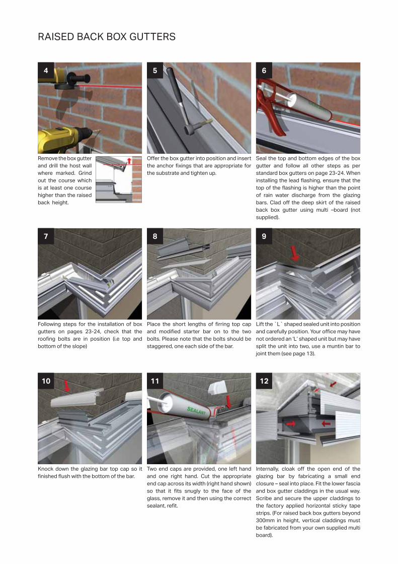
RAISED BACK BOX GUTTERS
RAISED BACK BOX GUTTERS
Remove the box gutter and drill the host wall where marked. Grind out the course which is at least one course higher than the raised back height.
4
Seal the top and bottom edges of the box gutter and follow all other steps as per standard box gutters on page 23-24. When installing the lead ashing, ensure that the top of the ashing is higher than the point of rain water discharge from the glazing bars. Clad o the deep skirt of the raised back box gutter using multi –board (not supplied).
6
O er the box gutter into position and insert the anchor xings that are appropriate for the substrate and tighten up.
5
Knock down the glazing bar top cap so it nished ush with the bottom of the bar.
10
Internally, cloak o the open end of the glazing bar by fabricating a small end closure – seal into place. Fit the lower fascia and box gutter claddings in the usual way. Scribe and secure the upper claddings to the factory applied horizontal sticky tape strips. (For raised back box gutters beyond 300mm in height, vertical claddings must be fabricated from your own supplied multi board).
11
Following steps for the installation of box gutters on pages 23-24, check that the roo ng bolts are in position (i.e top and bottom of the slope)
7
Lift the ̀ L` shaped sealed unit into position and carefully position. Your o ce may have not ordered an ‘L’ shaped unit but may have split the unit into two, use a muntin bar to joint them (see page 13).
9
Place the short lengths of rring top cap and modi ed starter bar on to the two bolts. Please note that the bolts should be staggered, one each side of the bar.
8
Two end caps are provided, one left hand and one right hand. Cut the appropriate end cap across its width (right hand shown) so that it ts snugly to the face of the glass, remove it and then using the correct sealant, re t.
12

27

Job No.: 3563 Ultrasky Roof Install 08/2018 V4 LAN026 It is Ultraframe’s policy to continually seek to improve its products, processes and services, and we reserve the right to change speci cations without prior notice. Ultraframe is a trading name of Ultraframe (UK) Limited.
www.ultraframetrade.co.uk