installation guide, cr4 battery pack charger for 81 ... · td 92724en 26 september 2011 / ver. b...
TRANSCRIPT
TD 92724EN
26 September 2011 / Ver. B
Installation GuideCR4, Battery Pack Charger

TD 92724EN
26 September 2011 / Ver. B
Installation GuideCR4 Battery Pack Charger
Contents
1 Introduction....................................................................................................................... 1
1.1 Safety ............................................................................................................................................. 3
1.2 Compliance .................................................................................................................................... 3
1.2.1 Regulatory Compliance Statements (EU/EFTA only) ............................................... 3
1.2.2 Regulatory Compliance Statements (USA/Canada only) ........................................ 3
1.3 Technical Solution ....................................................................................................................... 4
2 Installation and Configuration ........................................................................................ 5
2.1 CR4 Installation ............................................................................................................................ 5
2.1.1 General ................................................................................................................................. 5
2.1.2 Wall mounting ................................................................................................................... 6
2.1.3 Electrical installation ........................................................................................................ 6
3 Commissioning ................................................................................................................ 12
4 Operation ......................................................................................................................... 13
5 Troubleshooting .............................................................................................................. 14
6 Related Documents......................................................................................................... 15
7 Document History ........................................................................................................... 16
TD 92724ENInstallation GuideCR4 Battery Pack Charger
1 Introduction
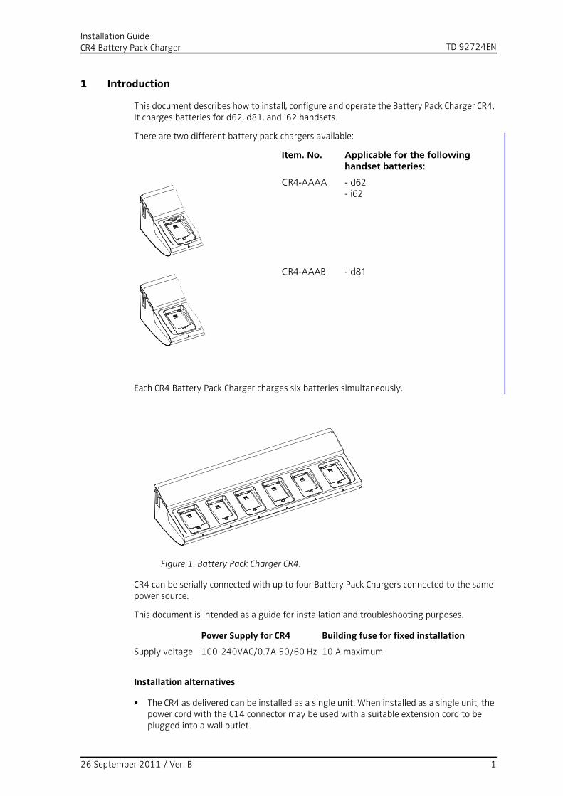
This document describes how to install, configure and operate the Battery Pack Charger CR4. It charges batteries for d62, d81, and i62 handsets.
There are two different battery pack chargers available:
Each CR4 Battery Pack Charger charges six batteries simultaneously.
Figure 1. Battery Pack Charger CR4.
CR4 can be serially connected with up to four Battery Pack Chargers connected to the same power source.
This document is intended as a guide for installation and troubleshooting purposes.
Installation alternatives
• The CR4 as delivered can be installed as a single unit. When installed as a single unit, the power cord with the C14 connector may be used with a suitable extension cord to be plugged into a wall outlet.
Item. No. Applicable for the following handset batteries:
CR4-AAAA - d62- i62
CR4-AAAB - d81
Figure 1.
Power Supply for CR4 Building fuse for fixed installation
Supply voltage 100-240VAC/0.7A 50/60 Hz 10 A maximum
26 September 2011 / Ver. B 1

TD 92724ENInstallation GuideCR4 Battery Pack Charger
• If more than one CR4 is used in a serial configuration a fixed installation must be made. For safety reasons it is not allowed to supply more than one unit by the power cord with the C14 connector. When units are supplied in series, the installation must be made by an authorized electrician and the C14 connectors must be removed. Maximum five units may be connected in serial power supply.
In Sweden, Norway and Finland a connection to protective earth (safety grounding) must be provided.
In the USA and Canada the CR4 must only be installed as a single unit, serial configuration is not permitted.
26 September 2011 / Ver. B 2
TD 92724ENInstallation GuideCR4 Battery Pack Charger
1.1 Safety
The Battery Pack Charger CR4 shall be connected to 100-240VAC/0.7A 50/60 Hz.For safety reasons:
• the safety covers on top of the supply voltage terminal blocks must be mounted to prevent hazardous situations, like electric shock.
• when servicing the units the mains power supply cable must be disconnected.
Note the following:
- for PERMANENTLY CONNECTED EQUIPMENT, a readily accessible disconnect device shall be incorporated in the building installation wiring. The disconnect device shall disconnect both poles.
- for PLUGGABLE EQUIPMENT, the socket-outlet shall be installed near the equipment and shall be easily accessible.
In Sweden, Norway and Finland the unit must be connected to a wall outlet with protective earth (safety grounding). For other countries it is recommended to use a protective earth connection.
• Suomi: Laite on liitettävä suojamaadoituskoskettimilla varustettuun pistorasiaan.
• Norge: Apparatet må tillkoples jordet stikkontakt.
• Sverige: Apparaten skall anslutas till jordat uttag.
1.2 Compliance
1.2.1 Regulatory Compliance Statements (EU/EFTA only)
This equipment is intended to be used in the whole EU & EFTA.
This equipment is in compliance with the essential requirements and other relevant provisions of R&TTE Directive 1999/5/EC. The Declaration of Conformity may be consulted at: http://www.ascom.com/ws/products_ws.htm
The product is marked with .
1.2.2 Regulatory Compliance Statements (USA/Canada only)
FCC Compliance Statements for USA
This equipment has been tested and found to comply with the limits for a Class B digital device, pursuant to part 15 of the FCC Rules. These limits are designed to provide reasonable protection against harmful interference in a residential installation. This equipment generates, uses and can radiate radio frequency energy and, if not installed and used in accordance with the instructions, may cause harmful interference to radio communications. However, there is no guarantee that interference will not occur in a particular installation. If this equipment does cause harmful interference to radio or television reception, which can be determined by turning the equipment off and on, the user is encouraged to try to correct the interference by one or more of the following measures:
• Reorient or relocate the receiving antenna
• Increase the separation between the equipment and receiver
26 September 2011 / Ver. B 3

TD 92724ENInstallation GuideCR4 Battery Pack Charger
IC Requirements for Canada
This Class B digital apparatus complies with Canadian ICES-003.
Cet appareil numérique de la Classe B conforme á la norme NMB-003 du Canada.
1.3 Technical Solution
The following functionality is provided by the CR4:
• Charging of the handset battery.
26 September 2011 / Ver. B 4

TD 92724ENInstallation GuideCR4 Battery Pack Charger
2 Installation and Configuration
2.1 CR4 Installation
2.1.1 General
• IMPORTANT: The unit shall be installed by authorized personnel only.
• The units shall be placed in a dry environment with a temperature range from+5° C up to + 40° C (41° F to 104° F).
• The units shall be mounted on a vertical wall.
• Avoid mounting the CR4 Battery Pack Charger in a sunlit place. This can affect the charging capacity.
• The unit shall be mounted on concrete or plaster walls only.
• If the CR4 is connected to a power supply via an AC wall plug, serial power supply connection is not allowed.
• When using a fixed connection, up to five CR4 Battery Pack Chargers or CR3 Rack Chargers can be serially connected to the same AC connection.
• If the CR4 is connected to a power supply via an AC wall plug, the socket-outlet shall be situated near the equipment and shall be easily accessible.
• If the CR4 is connected to a power supply via a fixed connection, a readily accessible disconnect device shall be incorporated in the building installation wiring.
Delivery includes:
• Battery Pack Charger
• Power supply cord including IEC C14 connector (male)
• Inlet accessory kit including cable support holders and screws
NOTE: An extension cord IEC C13 AC connector (female, IEC60320-C13) to wall socket has to be ordered separately. It shall be connected between the pre-installed IEC C14 AC connector (male) and the wall socket.
Required Tools etc.
• Screwdrivers
• Cutting pliers
• Multimeter
• Screws and wall plugs for wall mounting. Make sure the screws and wall plugs have the correct length for the type of wall used. See example below:
Examples of Ways to Mount the Battery Pack Chargers
The following picture shows different ways to mount CR4 Battery Pack Chargers. It is possible to set up different combinations of CR4 Battery Pack Chargers and Charging Racks.
Wall material Plug length Screw diameter
Single plasterboard Thorsman TP1 3.5 – 5 mm
Double plasterboard Thorsman TP2 3.5 – 5 mm
Concrete Thorsman TP2 3.5 – 5 mm
26 September 2011 / Ver. B 5
TD 92724ENInstallation GuideCR4 Battery Pack Charger
Installation steps
The installation is done in two steps:
1 Wall mounting.
2 Electrical installation.
2.1.2 Wall mounting
First, make an outline of how the battery pack chargers are to be placed.
Tip: If several CR4 Battery Pack Chargers (or CR3 Charging Racks) are to be mounted close to each other, mount them so that there is enough space between then to be able to disconnect the batteries or the handsets (vertical distance) and to be able to open the top cover (horizontal distance).
Tip: When you are planning the location of the modules, start to mount them in a height that makes it easy to reach the batteries.
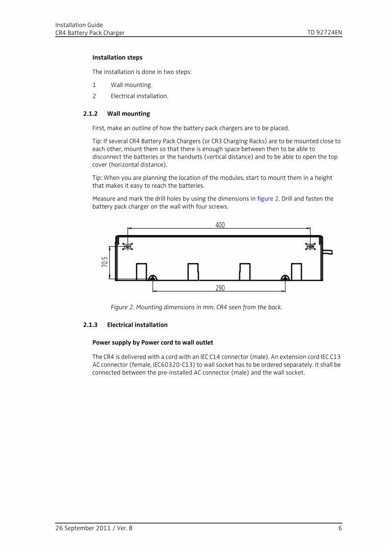
Measure and mark the drill holes by using the dimensions in figure 2. Drill and fasten the battery pack charger on the wall with four screws.
Figure 2. Mounting dimensions in mm. CR4 seen from the back.
2.1.3 Electrical installation
Power supply by Power cord to wall outlet
The CR4 is delivered with a cord with an IEC C14 connector (male). An extension cord IEC C13 AC connector (female, IEC60320-C13) to wall socket has to be ordered separately. It shall be connected between the pre-installed AC connector (male) and the wall socket.
Figure 2.
400
290
70.5
26 September 2011 / Ver. B 6
TD 92724ENInstallation GuideCR4 Battery Pack Charger
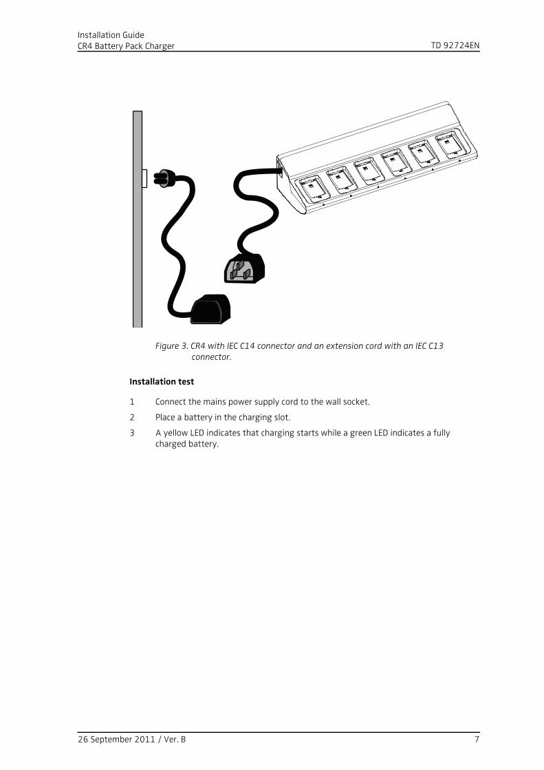
Figure 3. CR4 with IEC C14 connector and an extension cord with an IEC C13 connector.
Installation test
1 Connect the mains power supply cord to the wall socket.
2 Place a battery in the charging slot.
3 A yellow LED indicates that charging starts while a green LED indicates a fully charged battery.
Figure 3.
26 September 2011 / Ver. B 7
TD 92724ENInstallation GuideCR4 Battery Pack Charger
Power supply by fixed connection
NOTE: If the charging rack shall be connected with a fixed connection, the AC connection must be done by a authorized electrician.
Tip: It is possible to use any one of the two AC terminal blocks for AC input. Consequently, the unused terminal block may be used to connect the next charging rack or battery pack charger.
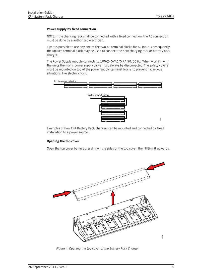
The Power Supply module connects to 100-240VAC/0.7A 50/60 Hz. When working with the units the mains power supply cable must always be disconnected. The safety covers must be mounted on top of the power supply terminal blocks to prevent hazardous situations, like electric chock..
Examples of how CR4 Battery Pack Chargers can be mounted and connected by fixed installation to a power source.
Opening the top cover
Open the top cover by first pressing on the sides of the top cover, then lifting it upwards.
Figure 4. Opening the top cover of the Battery Pack Charger.
Figure 4.
Figure 5.
To disconnect device
009
To disconnect device
005
26 September 2011 / Ver. B 8
TD 92724ENInstallation GuideCR4 Battery Pack Charger
Fixed installation in detail
Fixed installation of the first charger or single unit with fixed electrical installation.
1 Remove the C14 connector from the power cord. Measure cut and strip the power cord to be connected to the disconnect device.
2 Connect the mains power supply cord to the disconnect device.
The IEC color code is used in the power cord supplied.
Table 1: Wiring Color Codes
Installation of additional units in a serial power configuration
NOTE: Maximum five units may be connected in power series.
IMPORTANT: It is not allowed to connect additional charging racks or battery pack chargers if the chargers are connected to the power supply via an AC plug. Additionally, disconnect the power supply connection before working on the units.
1 If the additional charging rack has not yet been mounted on the wall, do this according to figure 2 on page 6.
2 Open the top cover of the rack charger closer to the AC power source.
3 Remove the cover which protects the unused AC output terminal block of the charger closer to the AC power source.
Colors
IEC US Old * Load Also called
Brown Black Red Active Line, Hot
Blue White Black Neutral Return, Cold, Grounded connector
Gr/Ye ** Green Green Earth Ground, Safety Earth, Earth Ground, Grounding conductor ***
* The "Old" standard was used in various countries (including Australia), and some wiring may still use these colours.
** Gr/Ye - Green with Yellow stripe - this is the standard world wide, although it is not common in the US or Canada at present.
*** There is an important distinction between "Grounding conductor" (safety earth) and "Grounded conductor" (Neutral). These are US terms for the conductors and they are not interchangeable, despite the similarity of the names !
26 September 2011 / Ver. B 9
TD 92724ENInstallation GuideCR4 Battery Pack Charger
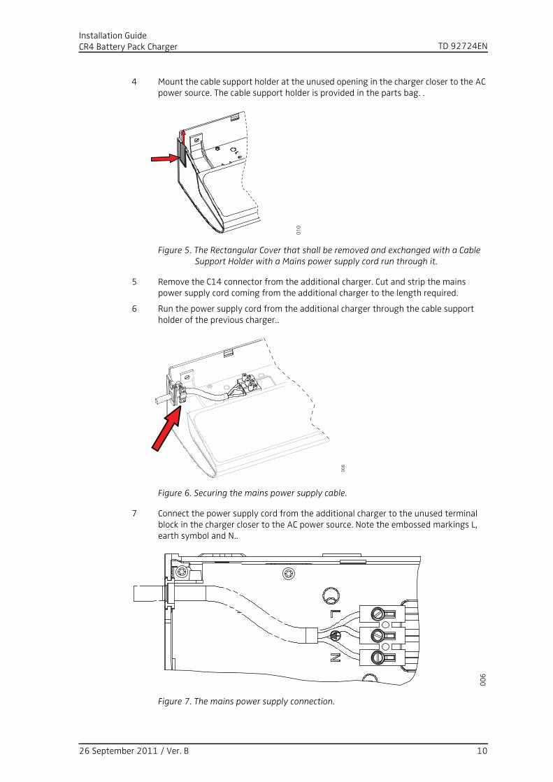
4 Mount the cable support holder at the unused opening in the charger closer to the AC power source. The cable support holder is provided in the parts bag. .
Figure 5. The Rectangular Cover that shall be removed and exchanged with a Cable Support Holder with a Mains power supply cord run through it.
5 Remove the C14 connector from the additional charger. Cut and strip the mains power supply cord coming from the additional charger to the length required.
6 Run the power supply cord from the additional charger through the cable support holder of the previous charger..
Figure 6. Securing the mains power supply cable.
7 Connect the power supply cord from the additional charger to the unused terminal block in the charger closer to the AC power source. Note the embossed markings L, earth symbol and N..
Figure 7. The mains power supply connection.
Figure 6.
Figure 7.
Figure 8.
010
008
006
26 September 2011 / Ver. B 10
TD 92724ENInstallation GuideCR4 Battery Pack Charger
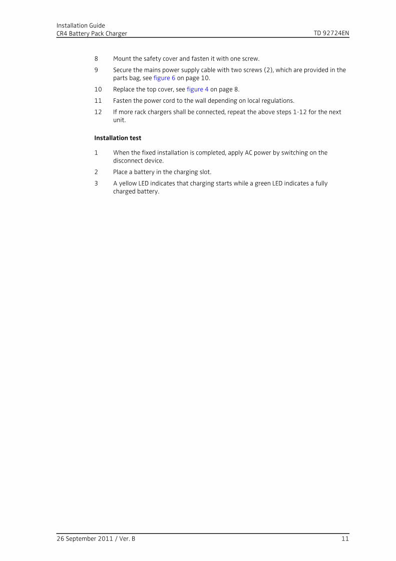
8 Mount the safety cover and fasten it with one screw.
9 Secure the mains power supply cable with two screws (2), which are provided in the parts bag, see figure 6 on page 10.
10 Replace the top cover, see figure 4 on page 8.
11 Fasten the power cord to the wall depending on local regulations.
12 If more rack chargers shall be connected, repeat the above steps 1-12 for the next unit.
Installation test
1 When the fixed installation is completed, apply AC power by switching on the disconnect device.
2 Place a battery in the charging slot.
3 A yellow LED indicates that charging starts while a green LED indicates a fully charged battery.
26 September 2011 / Ver. B 11

TD 92724ENInstallation GuideCR4 Battery Pack Charger
3 Commissioning
The commissioning includes the following:
• Installation test
• Charging
Installation test
For Installation test, see chapter Installation test on page 7 or page 11.
Charging
IMPORTANT: It is not allowed to charge an EX classified battery pack alone. Do not place the EX classified battery pack in the charging slot.
To verify that the charging works, follow these instructions.
1 Place a battery in a charging slot.
2 A yellow LED indicates that the charging has started while a green LED indicates a fully charged battery.
26 September 2011 / Ver. B 12
TD 92724ENInstallation GuideCR4 Battery Pack Charger
4 Operation
When the charger is connected to external power supply, normal operation is done as follows:
Charging
1 Connect the charger to the AC power supply.
2 Place a battery in the charging slot to start charging. Secure the battery by moving the lock switch.
Battery disconnection
1 Unlock the lock switch on the battery.
2 Remove the battery by lifting it.
26 September 2011 / Ver. B 13

TD 92724ENInstallation GuideCR4 Battery Pack Charger
5 Troubleshooting
Fault Solution
Charging does not start - Check that the battery is properly inserted in the charger.
- Check the AC power supply connection.
26 September 2011 / Ver. B 14
TD 92724ENInstallation GuideCR4 Battery Pack Charger
6 Related Documents
Data Sheet, CR4 Battery Pack Charger TD 92723GB
Data Sheet, CR3 Charging Rack TD 92721GB
Installation and Operation Manual, CR3 Charging Rack TD 92480EN
26 September 2011 / Ver. B 15
TD 92724ENInstallation GuideCR4 Battery Pack Charger
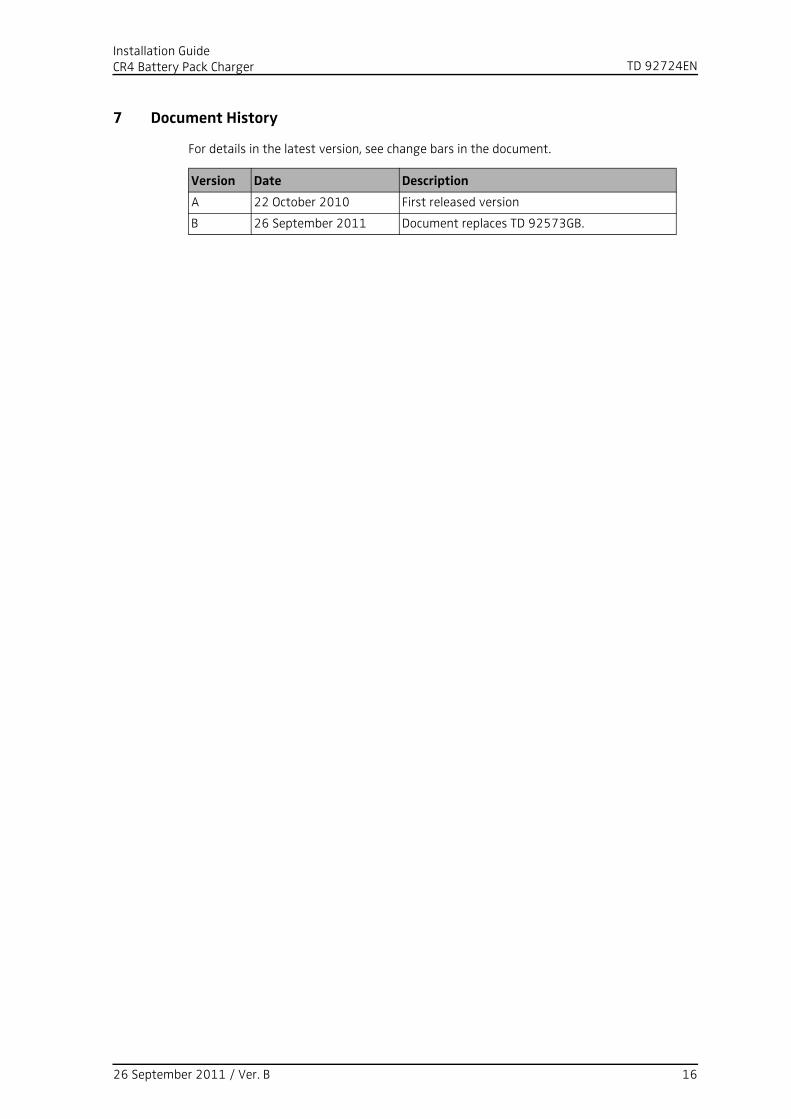
7 Document History
For details in the latest version, see change bars in the document.
Version Date Description
A 22 October 2010 First released version
B 26 September 2011 Document replaces TD 92573GB.
26 September 2011 / Ver. B 16