installation guide ethernet/ip card
TRANSCRIPT
Installation Guide
EtherNet/IP CardVLT® Soft Starter MCD 600
vlt-drives.danfoss.com

11.1
1.2
22.1
2.2
2.3
33.1
3.2
3.2.1
3.2.2
3.2.3
3.3
3.4
44.1
4.2
4.3
4.4
4.5
4.5.1
4.5.2
4.5.2.1
4.5.2.2
4.5.3
4.5.4
4.5.4.1
4.5.4.2
4.6
4.6.1
55.1
5.2
ContentsSafety 6
Disclaimer 6
Warnings 6
Introduction 7Product Design 7
Compatibility 7
Network Connection 7
Installation 8Installing the Expansion Card 8
Network Connections 8
Ethernet Ports 8
Cables 8
EMC Precautions 8
Network Establishment 8
Addressing 8
Device Configuration 9Before Configuring the Device 9
Configuration Methods 9
Parameters for Configuring Network Settings 9
Enabling Network Control 9
On-board Web Server 10
Connect to the Device 10
Manage Users and Passwords 11
Adding a User 11
Deleting a User 11
Configuring the IP Address 12
Configure IoT Settings 12
Configuring MQTT Settings 13
Configuring OPC UA Settings 14
Scanning the Network 14
Identifying the Device with Ethernet Device Configuration Tool 14
Scanner Configuration 16EDS File 16
Assembly Objects 16
AN353423548483en-000101/130R0945 | 3Danfoss A/S © 2020.12
Contents
EtherNet/IP Card
Installation Guide
66.1
6.2
6.3
6.4
77.1
7.1.1
7.1.2
7.1.2.1
7.1.2.2
7.1.2.3
7.1.3
7.1.3.1
7.1.3.2
7.1.3.3
7.1.3.4
7.1.3.5
7.2
7.2.1
7.2.2
7.2.2.1
7.2.2.2
7.2.2.3
7.2.3
7.2.3.1
7.2.3.2
88.1
8.2
8.2.1
99.1
9.2
9.3
9.4
Operation 17Requirements for Successful Operation 17
Device Classification 17
Ensuring Safe and Successful Control 17
Feedback LEDs 17
Messaging 18Implicit Messaging (Cyclic Operation) 18
Assembly Objects 16
Control Commands (Assembly Instance 104d) 18
Bytes 0–1: Command 18
Bytes 2–3: Reserved 18
Command Examples 18
Status Information (Assembly Instance 154d) 19
Bytes 0–1: Starter State 19
Bytes 2–3: Reserved 19
Bytes 4–7: Motor Current 19
Bytes 8–9: Trip Code 20
Bytes 10–11: Reserved 20
Explicit Messaging (Acyclic Operation) 20
Identity Object (Class 0x01) 20
Vendor-specific Objects 20
Class 100 and 101 Objects (Read/Write) 20
Class 103 Objects (Read Only) 20
Class 104 Objects (Read Only) 22
Supported Services for Vendor-specific Objects 22
Service Codes for Acyclic Operation 23
Status Codes for Acyclic Services 23
Attributes 24Trip Codes 24
Parameter Lists 25
Parameters, Class 100 and Class 101 Objects (Read/Write) 26
Network Design 30Star Topology 30
Line Topology 30
Ring Topology 31
Combined Topologies 31
AN353423548483en-000101/130R09454 | Danfoss A/S © 2020.12
Contents
EtherNet/IP Card
Installation Guide

1010.1
10.2
10.3
10.4
10.5
Specifications 33Connections 33
Settings 33
Network 33
Power 33
Certification 33
AN353423548483en-000101/130R0945 | 5Danfoss A/S © 2020.12
Contents
EtherNet/IP Card
Installation Guide
-
--
1 Safety
1.1 DisclaimerThe examples and diagrams in this manual are included solely for illustrative purposes. The information contained in this manual issubject to change at any time and without prior notice. Responsibility or liability is never accepted for direct, indirect, or consequen-tial damage resulting from the use or application of this equipment.
1.2 Warnings
W A R N I N GSHOCK HAZARDAttaching or removing accessories while the soft starter is connected to mains voltage may cause personal injury.
Before attaching or removing accessories, isolate the soft starter from mains voltage.
W A R N I N GRISK OF PERSONAL INJURY AND EQUIPMENT DAMAGEInserting foreign objects or touching the inside of the soft starter while the expansion port cover is open may endanger person-nel and can damage the soft starter.
Do not insert foreign objects in the soft starter with the port cover open.
Do not touch the inside of the soft starter with the port cover open.
AN353423548483en-000101 / 130R09456 | Danfoss A/S © 2020.12
Safety
EtherNet/IP Card
Installation Guide
2 Introduction
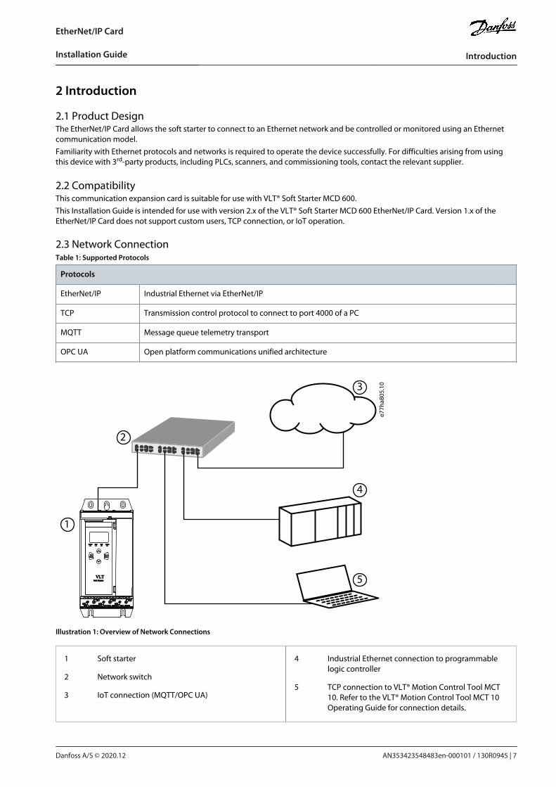
2.1 Product DesignThe EtherNet/IP Card allows the soft starter to connect to an Ethernet network and be controlled or monitored using an Ethernetcommunication model.Familiarity with Ethernet protocols and networks is required to operate the device successfully. For difficulties arising from usingthis device with 3rd-party products, including PLCs, scanners, and commissioning tools, contact the relevant supplier.
2.2 CompatibilityThis communication expansion card is suitable for use with VLT® Soft Starter MCD 600.This Installation Guide is intended for use with version 2.x of the VLT® Soft Starter MCD 600 EtherNet/IP Card. Version 1.x of theEtherNet/IP Card does not support custom users, TCP connection, or IoT operation.
2.3 Network ConnectionTable 1: Supported Protocols
Protocols
EtherNet/IP Industrial Ethernet via EtherNet/IP
TCP Transmission control protocol to connect to port 4000 of a PC
MQTT Message queue telemetry transport
OPC UA Open platform communications unified architecture
4/T2
READY RUN TRIP LOCAL
ExitReset
MenuStore
2/T1 6/T31/L1 3/L2 5/L3
VLT®
Soft Starter
1
2
4
3
5
e77h
a805
.10
Illustration 1: Overview of Network Connections
1 Soft starter
2 Network switch
3 IoT connection (MQTT/OPC UA)
4 Industrial Ethernet connection to programmablelogic controller
5 TCP connection to VLT® Motion Control Tool MCT10. Refer to the VLT® Motion Control Tool MCT 10Operating Guide for connection details.
AN353423548483en-000101 / 130R0945 | 7Danfoss A/S © 2020.12
Introduction
EtherNet/IP Card
Installation Guide

1.
2.
•
•
•
•
•
•
3 Installation
3.1 Installing the Expansion Card
1 2
e77h
a739
.10
Procedure
Push a small flat-bladed screwdriver into the slot in the center of the expansion port cover and ease the cover away fromthe soft starter.Align the card with the expansion port. Gently push the card along the guide rails until it clicks into the soft starter.
3.2 Network Connections
3.2.1 Ethernet PortsThe device has 2 Ethernet ports. If only 1 connection is required, either port can be used.
3.2.2 CablesWhen connecting to the device, make sure that the cables are of 1 of the following categories:
Category 5
Category 5e
Category 6
Category 6e
3.2.3 EMC PrecautionsTo minimize electromagnetic interference, Ethernet cables should be separated from motor and mains cables by 200 mm (7.9 in).If the Ethernet cable must cross motor or mains cables, the crossing should be at an angle of 90°.
3.3 Network EstablishmentThe controller must establish communications directly with each device before the device can participate in the network.
3.4 AddressingEach device in a network is addressed using a MAC address and an IP address.
The device can be assigned a static IP address during configuration or can be configured to accept a dynamic IP address (viaDHCP).
The MAC address is fixed within the device and is printed on a label on the front of the device.
AN353423548483en-000101 / 130R09458 | Danfoss A/S © 2020.12
Installation
EtherNet/IP Card
Installation Guide
•
•
•
4 Device Configuration
4.1 Before Configuring the Device
N O T I C EThe error LED flashes whenever the device is receiving power but is not connected to a network. The error LED will flash occa-sionally during the configuration process.
N O T I C EAt power-up, the communication card loads the IP address stored in the soft starter.
4.2 Configuration MethodsNetwork communication parameters for the communication card can be set via the soft starter or via the on-board web server.
The card uses a static IP address by default. To enable DHCP addressing, set parameter 12–20 DHCP to enable or change thesetting via the on-board web server.
The IP address can be set via the programmable parameters of the soft starter.
The web server can configure the IP address and messaging settings for MQTT/OPC UA operation.
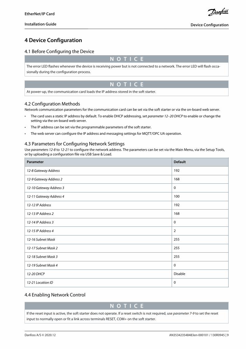
4.3 Parameters for Configuring Network SettingsUse parameters 12-8 to 12-21 to configure the network address. The parameters can be set via the Main Menu, via the Setup Tools,or by uploading a configuration file via USB Save & Load.
Parameter Default
12-8 Gateway Address 192
12-9 Gateway Address 2 168
12-10 Gateway Address 3 0
12-11 Gateway Address 4 100
12-12 IP Address 192
12-13 IP Address 2 168
12-14 IP Address 3 0
12-15 IP Address 4 2
12-16 Subnet Mask 255
12-17 Subnet Mask 2 255
12-18 Subnet Mask 3 255
12-19 Subnet Mask 4 0
12-20 DHCP Disable
12-21 Location ID 0
4.4 Enabling Network Control
N O T I C EIf the reset input is active, the soft starter does not operate. If a reset switch is not required, use parameter 7-9 to set the resetinput to normally open or fit a link across terminals RESET, COM+ on the soft starter.
AN353423548483en-000101 / 130R0945 | 9Danfoss A/S © 2020.12
Device Configuration
EtherNet/IP Card
Installation Guide
1.
Procedure
Set parameter 1-1 Command Source to Network for the soft starter to accept commands from the EtherNet/IP Card.
4.5 On-board Web Server
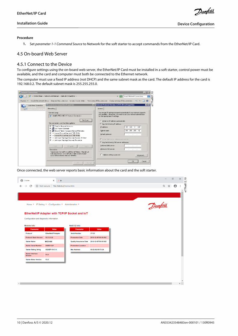
4.5.1 Connect to the DeviceTo configure settings using the on-board web server, the EtherNet/IP Card must be installed in a soft starter, control power must beavailable, and the card and computer must both be connected to the Ethernet network.The computer must use a fixed IP address (not DHCP) and the same subnet mask as the card. The default IP address for the card is192.168.0.2. The default subnet mask is 255.255.255.0.
e77h
a807
.10
Once connected, the web server reports basic information about the card and the soft starter.
MCD 600
e77h
a812
.10
AN353423548483en-000101 / 130R094510 | Danfoss A/S © 2020.12
Device Configuration
EtherNet/IP Card
Installation Guide
•
•
•
1.2.3.4.5.6.
1.2.3.
--
4.5.2 Manage Users and Passwords
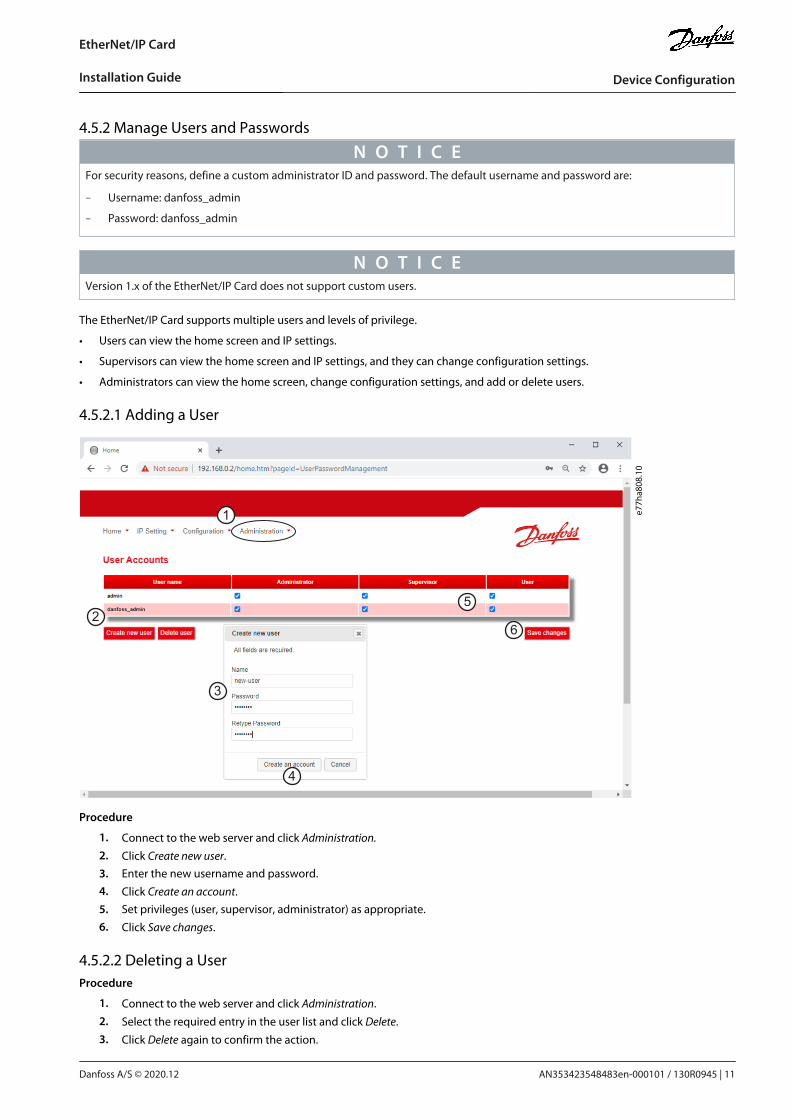
N O T I C EFor security reasons, define a custom administrator ID and password. The default username and password are:
Username: danfoss_admin
Password: danfoss_admin
N O T I C EVersion 1.x of the EtherNet/IP Card does not support custom users.
The EtherNet/IP Card supports multiple users and levels of privilege.
Users can view the home screen and IP settings.
Supervisors can view the home screen and IP settings, and they can change configuration settings.
Administrators can view the home screen, change configuration settings, and add or delete users.
4.5.2.1 Adding a User
1
2
3
5
6e7
7ha808
.10
4
Procedure
Connect to the web server and click Administration.
Click Create new user.Enter the new username and password.
Click Create an account.Set privileges (user, supervisor, administrator) as appropriate.
Click Save changes.
4.5.2.2 Deleting a UserProcedure
Connect to the web server and click Administration.
Select the required entry in the user list and click Delete.
Click Delete again to confirm the action.
AN353423548483en-000101 / 130R0945 | 11Danfoss A/S © 2020.12
Device Configuration
EtherNet/IP Card
Installation Guide

1.2.3.
4.5.3 Configuring the IP Address
N O T I C EFor version 1.x of the EtherNet/IP Card, changes made via the web server are not stored in the soft starter and will be lost whencontrol power is cycled.
1
2
3
e77h
a806
.10
Procedure
Connect to the web server and click IP Setting.Edit settings as required. To enable DHCP addressing, tick the DHCP checkbox.
Click Submit to send the new settings to the device.
4.5.4 Configure IoT SettingsThe EtherNet/IP Card supports soft starter status monitoring via IoT. The card cannot control or program the soft starter.
N O T I C EVersion 1.x of the EtherNet/IP Card does not support IoT operation.
AN353423548483en-000101 / 130R094512 | Danfoss A/S © 2020.12
Device Configuration
EtherNet/IP Card
Installation Guide

1.2.3.
4.5.6.
4.5.4.1 Configuring MQTT Settings
e77h
a810
.10
Procedure
Connect to the web server and click Configuration.
Select MQTT Client.
Tick the Enable checkbox to enable MQTT client operation.
The MQTT client is enabled by default.
Click Connection and configure the settings as required.
Click Connections⇒Actions to select which information the card should publish.
Click Submit to save all settings in the card.
AN353423548483en-000101 / 130R0945 | 13Danfoss A/S © 2020.12
Device Configuration
EtherNet/IP Card
Installation Guide

1.2.3.
4.5.6.
1.2.
4.5.4.2 Configuring OPC UA Settings
e77h
a813
.10
Procedure
Connect to the web server and click Configuration.
Select OPC UA Server.
Tick the Enable checkbox to enable OPC UA client operation.
The OPC UA client is enabled by default.
Click Server Configuration and configure the settings as required.
Select Actions to select the actions for different object instances.
Click Submit to save all settings in the card.
4.6 Scanning the NetworkIf there is no connection to the web server and the soft starter cannot be accessed physically, use the Ethernet Device ConfigurationTool to scan the network and identify the device. Changes made via the Ethernet Device Configuration Tool cannot be stored per-manently in the device and will be lost when the control power is cycled.Download the Ethernet Device Configuration Tool from www.danfoss.com under the sections Services/PC-tools.
N O T I C EIf the PC has a firewall enabled, add the tool to the list of authorized programs.
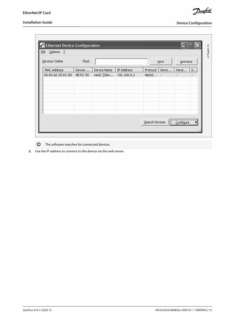
4.6.1 Identifying the Device with Ethernet Device Configuration ToolProcedure
Start the Ethernet Device Configuration Tool.
Click Search Devices.
AN353423548483en-000101 / 130R094514 | Danfoss A/S © 2020.12
Device Configuration
EtherNet/IP Card
Installation Guide
3.
e77h
a641
.10
The software searches for connected devices.
Use the IP address to connect to the device via the web server.
AN353423548483en-000101 / 130R0945 | 15Danfoss A/S © 2020.12
Device Configuration
EtherNet/IP Card
Installation Guide
5 Scanner Configuration
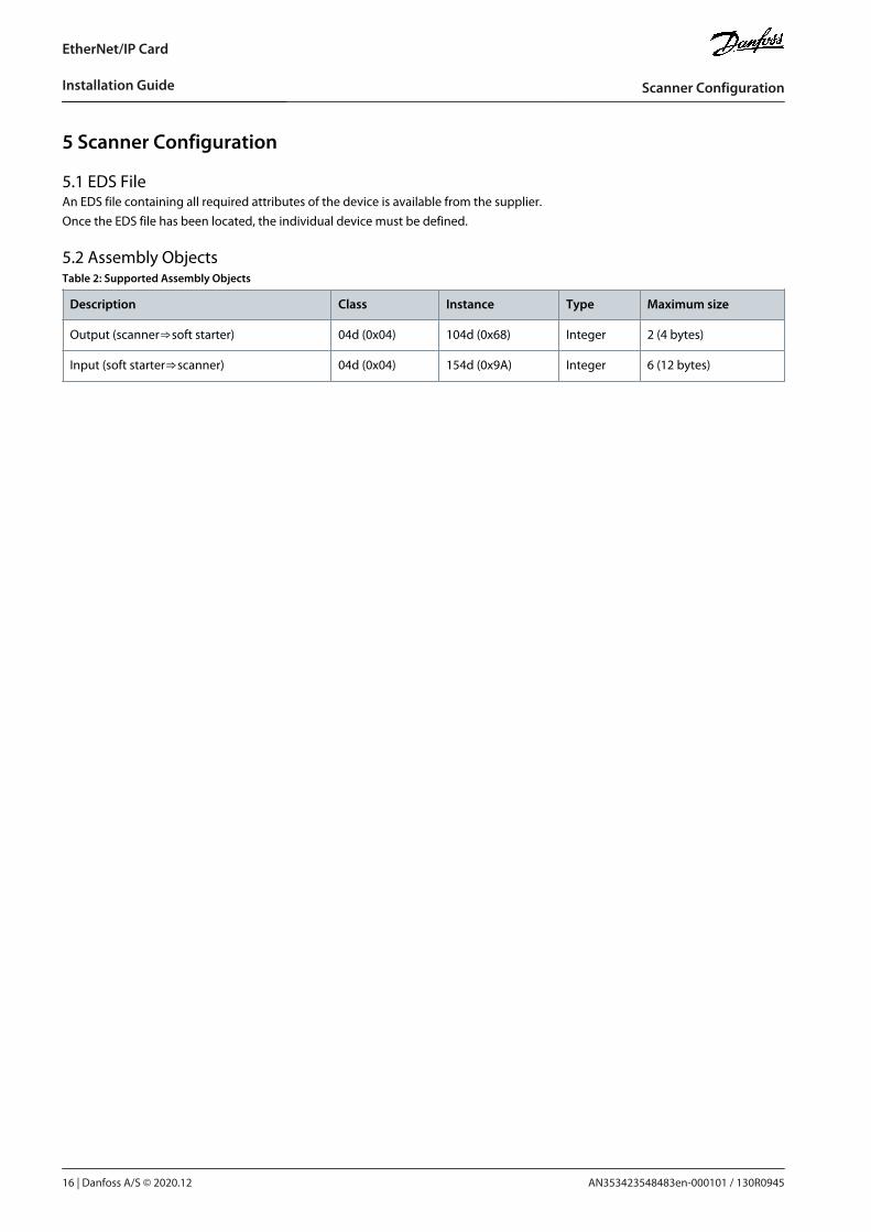
5.1 EDS FileAn EDS file containing all required attributes of the device is available from the supplier.Once the EDS file has been located, the individual device must be defined.
5.2 Assembly ObjectsTable 2: Supported Assembly Objects
Description Class Instance Type Maximum size
Output (scanner⇒soft starter) 04d (0x04) 104d (0x68) Integer 2 (4 bytes)
Input (soft starter⇒scanner) 04d (0x04) 154d (0x9A) Integer 6 (12 bytes)
AN353423548483en-000101 / 130R094516 | Danfoss A/S © 2020.12
Scanner Configuration
EtherNet/IP Card
Installation Guide
6 Operation
6.1 Requirements for Successful OperationThe EtherNet/IP Card is conformance tested to ODVA. For successful operation, the scanner must also support all functions andinterfaces described in this manual.
N O T I C EThe available features and parameter details may vary according to the model and software version of the soft starter. Refer tothe VLT® Soft Starter MCD 600 Operating Guide for details of parameters and supported features.
6.2 Device ClassificationThe EtherNet/IP Card is an I/O adapter and must be managed by an I/O scanner over Ethernet.The EtherNet/IP Card supports both implicit (cyclic) and explicit (acyclic) messaging.
6.3 Ensuring Safe and Successful ControlData written to the device remains in its registers until the data is overwritten or the device is reinitialized. If the soft starter is con-trolled via parameter 7-1 Command Override or is disabled via the reset input (terminals RESET, COM+), fieldbus commands shouldbe cleared from the registers. If a command is not cleared, it is re-sent to the soft starter once fieldbus control resumes.
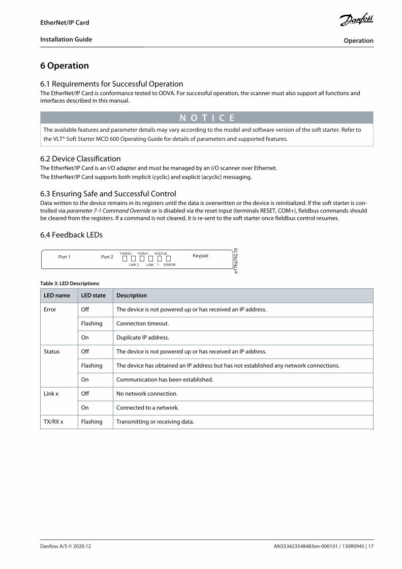
6.4 Feedback LEDs
Port 1 Port 2 Keypad
LINK 2
TX/RX2
LINK 1
TX/RX1
ERROR
STATUS
e77h
a742
.10
Table 3: LED Descriptions
LED name LED state Description
Error Off The device is not powered up or has received an IP address.
Flashing Connection timeout.
On Duplicate IP address.
Status Off The device is not powered up or has received an IP address.
Flashing The device has obtained an IP address but has not established any network connections.
On Communication has been established.
Link x Off No network connection.
On Connected to a network.
TX/RX x Flashing Transmitting or receiving data.
AN353423548483en-000101 / 130R0945 | 17Danfoss A/S © 2020.12
Operation
EtherNet/IP Card
Installation Guide
7 Messaging
7.1 Implicit Messaging (Cyclic Operation)This section lists the requirements related to cyclic (implicit messaging) services for the EtherNet/IP Card. The minimum cyclic inter-val is 1 ms. All data is in little endian format.
7.1.1 Assembly ObjectsTable 4: Supported Assembly Objects
Description Class Instance Type Maximum size
Output (scanner⇒soft starter) 04d (0x04) 104d (0x68) Integer 2 (4 bytes)
Input (soft starter⇒scanner) 04d (0x04) 154d (0x9A) Integer 6 (12 bytes)
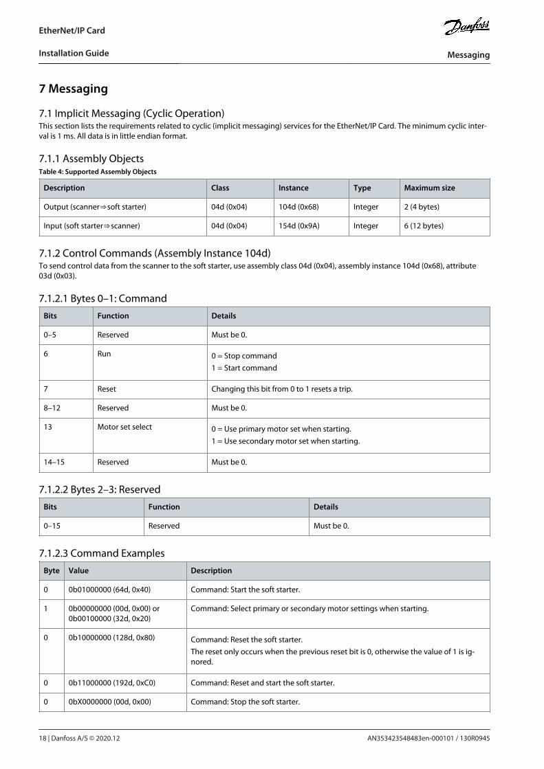
7.1.2 Control Commands (Assembly Instance 104d)To send control data from the scanner to the soft starter, use assembly class 04d (0x04), assembly instance 104d (0x68), attribute03d (0x03).
7.1.2.1 Bytes 0–1: Command
Bits Function Details
0–5 Reserved Must be 0.
6 Run 0 = Stop command1 = Start command
7 Reset Changing this bit from 0 to 1 resets a trip.
8–12 Reserved Must be 0.
13 Motor set select 0 = Use primary motor set when starting.1 = Use secondary motor set when starting.
14–15 Reserved Must be 0.
7.1.2.2 Bytes 2–3: Reserved
Bits Function Details
0–15 Reserved Must be 0.
7.1.2.3 Command Examples
Byte Value Description
0 0b01000000 (64d, 0x40) Command: Start the soft starter.
1 0b00000000 (00d, 0x00) or0b00100000 (32d, 0x20)
Command: Select primary or secondary motor settings when starting.
0 0b10000000 (128d, 0x80) Command: Reset the soft starter.The reset only occurs when the previous reset bit is 0, otherwise the value of 1 is ig-nored.
0 0b11000000 (192d, 0xC0) Command: Reset and start the soft starter.
0 0bX0000000 (00d, 0x00) Command: Stop the soft starter.
AN353423548483en-000101 / 130R094518 | Danfoss A/S © 2020.12
Messaging
EtherNet/IP Card
Installation Guide
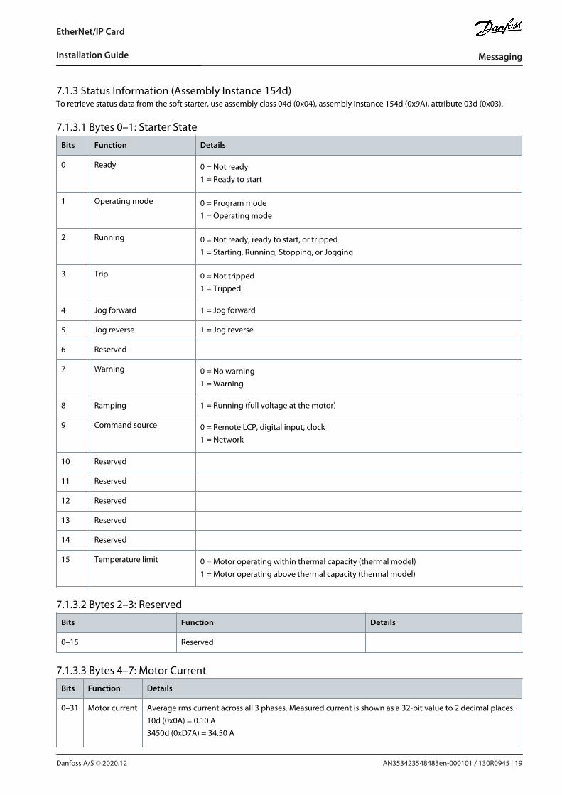
7.1.3 Status Information (Assembly Instance 154d)To retrieve status data from the soft starter, use assembly class 04d (0x04), assembly instance 154d (0x9A), attribute 03d (0x03).
7.1.3.1 Bytes 0–1: Starter State
Bits Function Details
0 Ready 0 = Not ready1 = Ready to start
1 Operating mode 0 = Program mode1 = Operating mode
2 Running 0 = Not ready, ready to start, or tripped1 = Starting, Running, Stopping, or Jogging
3 Trip 0 = Not tripped1 = Tripped
4 Jog forward 1 = Jog forward
5 Jog reverse 1 = Jog reverse
6 Reserved
7 Warning 0 = No warning1 = Warning
8 Ramping 1 = Running (full voltage at the motor)
9 Command source 0 = Remote LCP, digital input, clock1 = Network
10 Reserved
11 Reserved
12 Reserved
13 Reserved
14 Reserved
15 Temperature limit 0 = Motor operating within thermal capacity (thermal model)1 = Motor operating above thermal capacity (thermal model)
7.1.3.2 Bytes 2–3: Reserved
Bits Function Details
0–15 Reserved
7.1.3.3 Bytes 4–7: Motor Current
Bits Function Details
0–31 Motor current Average rms current across all 3 phases. Measured current is shown as a 32-bit value to 2 decimal places.10d (0x0A) = 0.10 A3450d (0xD7A) = 34.50 A
AN353423548483en-000101 / 130R0945 | 19Danfoss A/S © 2020.12
Messaging
EtherNet/IP Card
Installation Guide

•
•
Bits Function Details
68930d (0x10D42) = 689.30 A
7.1.3.4 Bytes 8–9: Trip Code
Bits Function Details
0–15 Trip code See the chapter Trip Codes.
7.1.3.5 Bytes 10–11: Reserved
Bits Function Details
0–15 Reserved
7.2 Explicit Messaging (Acyclic Operation)This section provides information on objects, instances, attributes, and services for acyclic operation (explicit messaging).All data is in little endian format.
7.2.1 Identity Object (Class 0x01)Table 5: Supported Attributes for Identity Objects
Attribute Function Value
1 Vendor 204d (0xCC)
2 Device type 12d (0x0C)
3 Product code 269d (0x10D)
4 Revision: Major, minor EDS file version
5 Status Supported
6 Serial number Supported
7 Product name Supported
7.2.2 Vendor-specific ObjectsThe EtherNet/IP Card supports vendor-specific classes 100, 101, 103, and 104.
7.2.2.1 Class 100 and 101 Objects (Read/Write)Class 100 and 101 objects allow parameter values to be read from and written to the soft starter.
Class 100d (0x64): Parameters 1–99
Class 101d (0x65): Parameters 100–199
See the chapter Parameter Lists for more details.
7.2.2.2 Class 103 Objects (Read Only)Class 103d (0x67) allows soft starter state information to be read from the soft starter.
N O T I C EFor models MCD6-0063B and smaller, current reported via communications is 10 times greater than the actual value shown onthe LCP.
AN353423548483en-000101 / 130R094520 | Danfoss A/S © 2020.12
Messaging
EtherNet/IP Card
Installation Guide
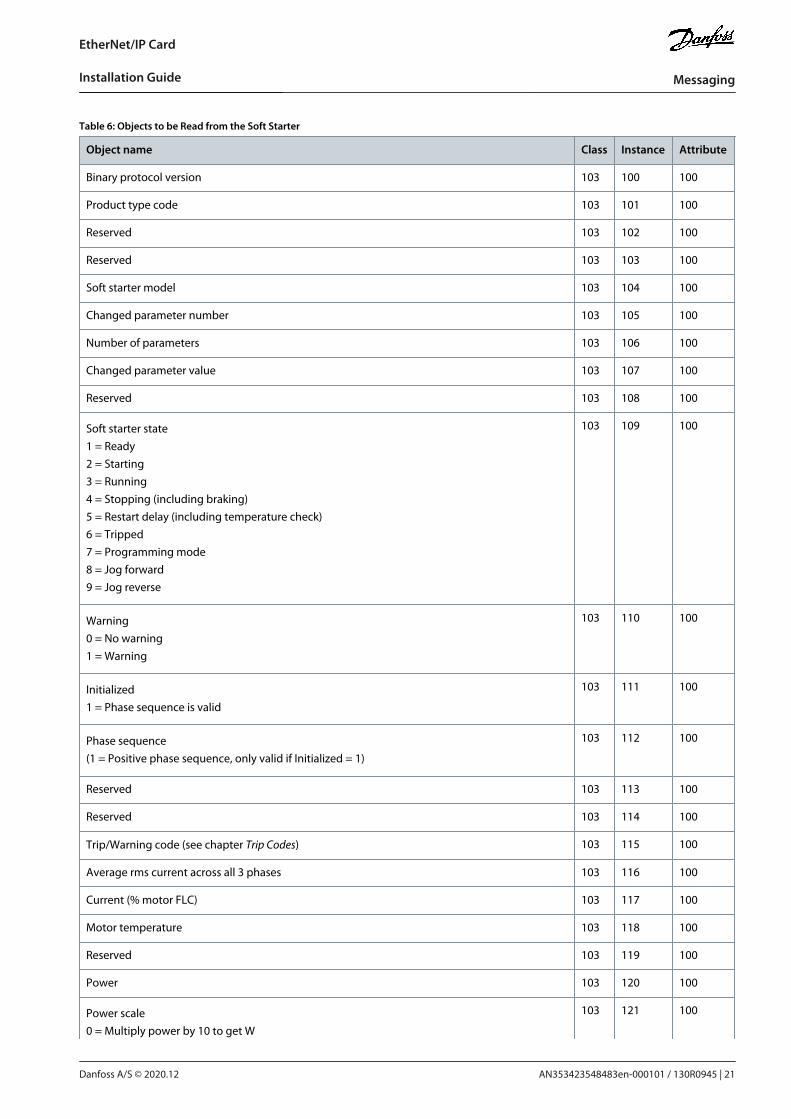
Table 6: Objects to be Read from the Soft Starter
Object name Class Instance Attribute
Binary protocol version 103 100 100
Product type code 103 101 100
Reserved 103 102 100
Reserved 103 103 100
Soft starter model 103 104 100
Changed parameter number 103 105 100
Number of parameters 103 106 100
Changed parameter value 103 107 100
Reserved 103 108 100
Soft starter state1 = Ready2 = Starting3 = Running4 = Stopping (including braking)5 = Restart delay (including temperature check)6 = Tripped7 = Programming mode8 = Jog forward9 = Jog reverse
103 109 100
Warning0 = No warning1 = Warning
103 110 100
Initialized1 = Phase sequence is valid
103 111 100
Phase sequence(1 = Positive phase sequence, only valid if Initialized = 1)
103 112 100
Reserved 103 113 100
Reserved 103 114 100
Trip/Warning code (see chapter Trip Codes) 103 115 100
Average rms current across all 3 phases 103 116 100
Current (% motor FLC) 103 117 100
Motor temperature 103 118 100
Reserved 103 119 100
Power 103 120 100
Power scale0 = Multiply power by 10 to get W
103 121 100
AN353423548483en-000101 / 130R0945 | 21Danfoss A/S © 2020.12
Messaging
EtherNet/IP Card
Installation Guide

Object name Class Instance Attribute
1 = Multiply power by 100 to get W2 = Power (kW)3 = Multiply power by 10 to get kW
% Power factor 103 122 100
Average rms voltage across all 3 phases 103 123 100
Phase 1 current 103 124 100
Phase 2 current 103 125 100
Phase 3 current 103 126 100
Phase 1 voltage 103 127 100
Phase 2 voltage 103 128 100
Phase 3 voltage 103 129 100
Parameter list minor version 103 130 100
Parameter list major version 103 131 100
Digital input stateFor all inputs, 0 = open, 1 = closed (short-circuited)Start/stop input = 01h, reset = 04h, programmable input A = 08h, programmable input B = 10h
103 132 100
N O T I C EThe reset input is normally closed by default. If parameter 7-9 Reset/Enable Logic is set to normally open, the reported state isinverted (0 = closed, 1 = open).
7.2.2.3 Class 104 Objects (Read Only)Class 104d (0x68) allows extended information to be read from the soft starter.
Object name Class Instance Attribute
Major software version - User interface 104 101 100
Minor software version - User interface 104 102 100
Major software version - Motor control 104 103 100
Minor software version - Motor control 104 104 100
Major software version - Remote LCP (if installed) 104 105 100
Minor software version - Remote LCP (if installed) 104 106 100
Major software version - Expansion card (if installed) 104 107 100
Minor software version -. Expansion card (if installed) 104 108 100
7.2.3 Supported Services for Vendor-specific ObjectsThis section describes the operational instructions to carry out acyclic services on class objects 100, 101, 103, and 104.
AN353423548483en-000101 / 130R094522 | Danfoss A/S © 2020.12
Messaging
EtherNet/IP Card
Installation Guide

•
•
7.2.3.1 Service Codes for Acyclic OperationTable 7: Supported Services for Vendor-specific Objects
Service code Function Description
01d (0x01) Get attribute all Only supported for class 0x01 identity object
10d (0x10) Set attribute single Supported
15d (0x0E) Get attribute single Supported
7.2.3.2 Status Codes for Acyclic ServicesTable 8: Status Codes Returned in Response to Get/Set Attribute Single
Status code Status name Details
00d (0x00) Success This code is returned when:
the register mapped for Get Attribute Single is successfully read.
the register mapped for "Set Attribute Single" is successfully set.
03d (0x03) Invalid parameter value –
05d (0x05) Path destination unknown The mapped register does not exist.
08d (0x08) Service not supported The requested service is not available for this object class/instance.
09d (0x09) Invalid attribute value This code only applies to the service Set Attribute Single. It is returned if the value isout of range of the mapped register.
15d (0x0E) Attribute not settable This code only applies to the service Set Attribute Single. It is returned if the mappedregister is read-only.
20d (0x14) Attribute not supported The attribute specified in the request is not supported.
22d (0x16) Object does not exist The object specified does not exist in the device.
AN353423548483en-000101 / 130R0945 | 23Danfoss A/S © 2020.12
Messaging
EtherNet/IP Card
Installation Guide
8 Attributes
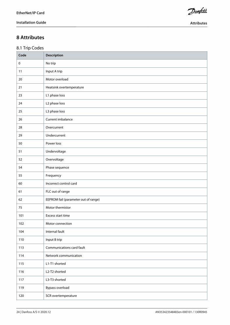
8.1 Trip Codes
Code Description
0 No trip
11 Input A trip
20 Motor overload
21 Heatsink overtemperature
23 L1 phase loss
24 L2 phase loss
25 L3 phase loss
26 Current imbalance
28 Overcurrent
29 Undercurrent
50 Power loss
51 Undervoltage
52 Overvoltage
54 Phase sequence
55 Frequency
60 Incorrect control card
61 FLC out of range
62 EEPROM fail (parameter out of range)
75 Motor thermistor
101 Excess start time
102 Motor connection
104 Internal fault
110 Input B trip
113 Communications card fault
114 Network communication
115 L1-T1 shorted
116 L2-T2 shorted
117 L3-T3 shorted
119 Bypass overload
120 SCR overtemperature
AN353423548483en-000101 / 130R094524 | Danfoss A/S © 2020.12
Attributes
EtherNet/IP Card
Installation Guide
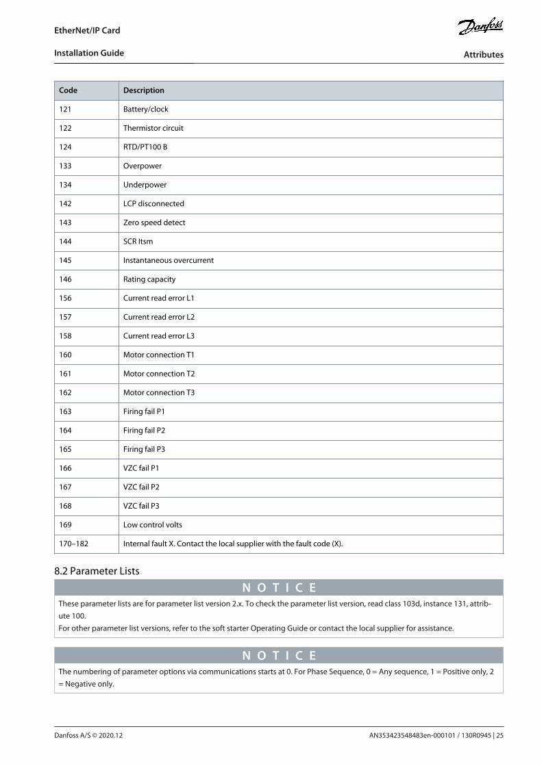
Code Description
121 Battery/clock
122 Thermistor circuit
124 RTD/PT100 B
133 Overpower
134 Underpower
142 LCP disconnected
143 Zero speed detect
144 SCR Itsm
145 Instantaneous overcurrent
146 Rating capacity
156 Current read error L1
157 Current read error L2
158 Current read error L3
160 Motor connection T1
161 Motor connection T2
162 Motor connection T3
163 Firing fail P1
164 Firing fail P2
165 Firing fail P3
166 VZC fail P1
167 VZC fail P2
168 VZC fail P3
169 Low control volts
170–182 Internal fault X. Contact the local supplier with the fault code (X).
8.2 Parameter Lists
N O T I C EThese parameter lists are for parameter list version 2.x. To check the parameter list version, read class 103d, instance 131, attrib-ute 100.For other parameter list versions, refer to the soft starter Operating Guide or contact the local supplier for assistance.
N O T I C EThe numbering of parameter options via communications starts at 0. For Phase Sequence, 0 = Any sequence, 1 = Positive only, 2= Negative only.
AN353423548483en-000101 / 130R0945 | 25Danfoss A/S © 2020.12
Attributes
EtherNet/IP Card
Installation Guide
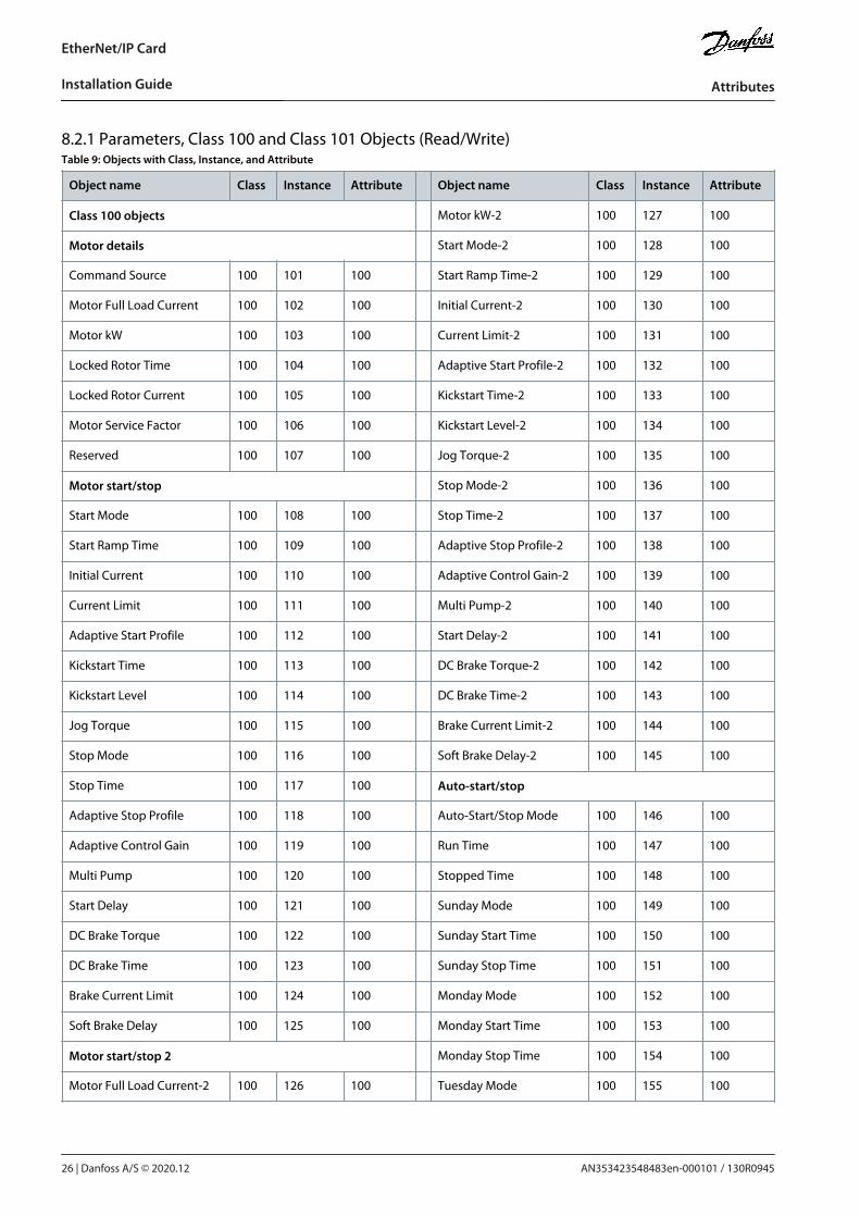
8.2.1 Parameters, Class 100 and Class 101 Objects (Read/Write)Table 9: Objects with Class, Instance, and Attribute
Object name Class Instance Attribute Object name Class Instance Attribute
Class 100 objects Motor kW-2 100 127 100
Motor details Start Mode-2 100 128 100
Command Source 100 101 100 Start Ramp Time-2 100 129 100
Motor Full Load Current 100 102 100 Initial Current-2 100 130 100
Motor kW 100 103 100 Current Limit-2 100 131 100
Locked Rotor Time 100 104 100 Adaptive Start Profile-2 100 132 100
Locked Rotor Current 100 105 100 Kickstart Time-2 100 133 100
Motor Service Factor 100 106 100 Kickstart Level-2 100 134 100
Reserved 100 107 100 Jog Torque-2 100 135 100
Motor start/stop Stop Mode-2 100 136 100
Start Mode 100 108 100 Stop Time-2 100 137 100
Start Ramp Time 100 109 100 Adaptive Stop Profile-2 100 138 100
Initial Current 100 110 100 Adaptive Control Gain-2 100 139 100
Current Limit 100 111 100 Multi Pump-2 100 140 100
Adaptive Start Profile 100 112 100 Start Delay-2 100 141 100
Kickstart Time 100 113 100 DC Brake Torque-2 100 142 100
Kickstart Level 100 114 100 DC Brake Time-2 100 143 100
Jog Torque 100 115 100 Brake Current Limit-2 100 144 100
Stop Mode 100 116 100 Soft Brake Delay-2 100 145 100
Stop Time 100 117 100 Auto-start/stop
Adaptive Stop Profile 100 118 100 Auto-Start/Stop Mode 100 146 100
Adaptive Control Gain 100 119 100 Run Time 100 147 100
Multi Pump 100 120 100 Stopped Time 100 148 100
Start Delay 100 121 100 Sunday Mode 100 149 100
DC Brake Torque 100 122 100 Sunday Start Time 100 150 100
DC Brake Time 100 123 100 Sunday Stop Time 100 151 100
Brake Current Limit 100 124 100 Monday Mode 100 152 100
Soft Brake Delay 100 125 100 Monday Start Time 100 153 100
Motor start/stop 2 Monday Stop Time 100 154 100
Motor Full Load Current-2 100 126 100 Tuesday Mode 100 155 100
AN353423548483en-000101 / 130R094526 | Danfoss A/S © 2020.12
Attributes
EtherNet/IP Card
Installation Guide
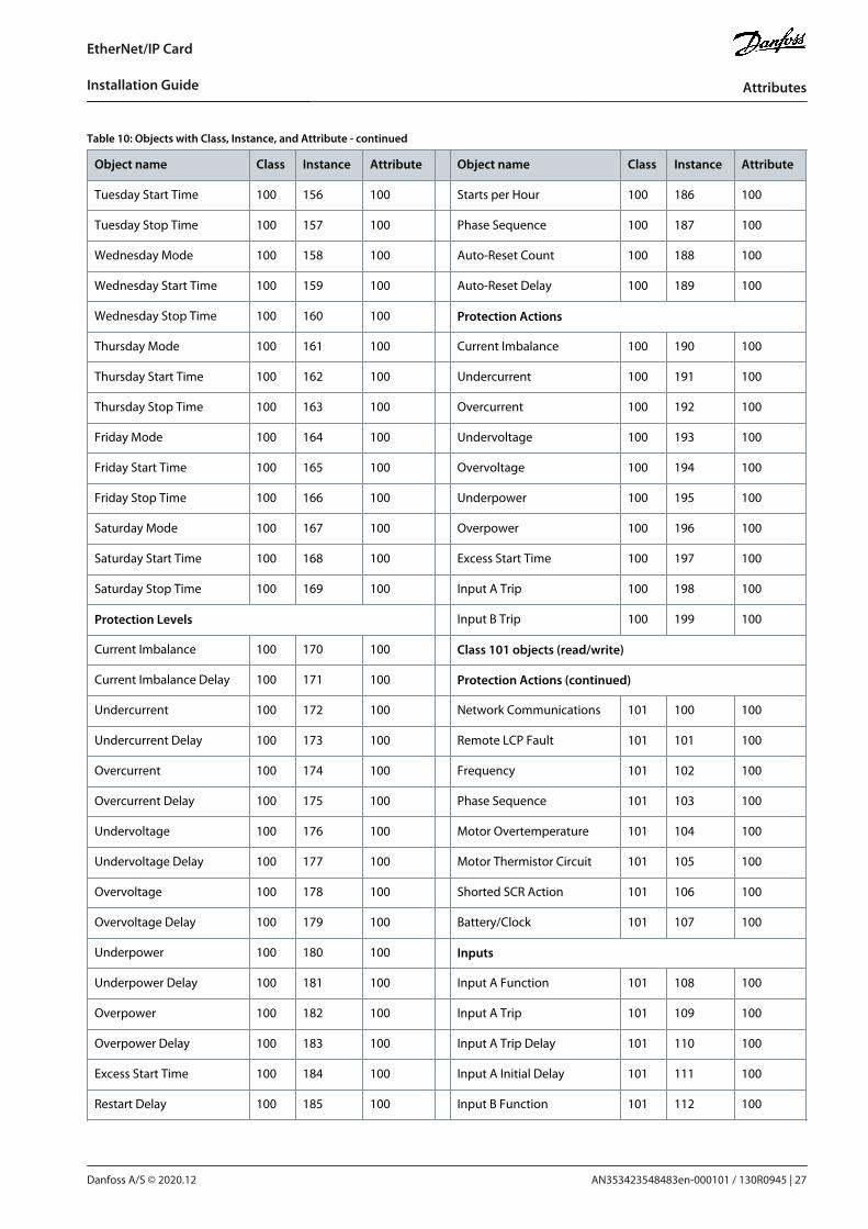
Table 10: Objects with Class, Instance, and Attribute - continued
Object name Class Instance Attribute Object name Class Instance Attribute
Tuesday Start Time 100 156 100 Starts per Hour 100 186 100
Tuesday Stop Time 100 157 100 Phase Sequence 100 187 100
Wednesday Mode 100 158 100 Auto-Reset Count 100 188 100
Wednesday Start Time 100 159 100 Auto-Reset Delay 100 189 100
Wednesday Stop Time 100 160 100 Protection Actions
Thursday Mode 100 161 100 Current Imbalance 100 190 100
Thursday Start Time 100 162 100 Undercurrent 100 191 100
Thursday Stop Time 100 163 100 Overcurrent 100 192 100
Friday Mode 100 164 100 Undervoltage 100 193 100
Friday Start Time 100 165 100 Overvoltage 100 194 100
Friday Stop Time 100 166 100 Underpower 100 195 100
Saturday Mode 100 167 100 Overpower 100 196 100
Saturday Start Time 100 168 100 Excess Start Time 100 197 100
Saturday Stop Time 100 169 100 Input A Trip 100 198 100
Protection Levels Input B Trip 100 199 100
Current Imbalance 100 170 100 Class 101 objects (read/write)
Current Imbalance Delay 100 171 100 Protection Actions (continued)
Undercurrent 100 172 100 Network Communications 101 100 100
Undercurrent Delay 100 173 100 Remote LCP Fault 101 101 100
Overcurrent 100 174 100 Frequency 101 102 100
Overcurrent Delay 100 175 100 Phase Sequence 101 103 100
Undervoltage 100 176 100 Motor Overtemperature 101 104 100
Undervoltage Delay 100 177 100 Motor Thermistor Circuit 101 105 100
Overvoltage 100 178 100 Shorted SCR Action 101 106 100
Overvoltage Delay 100 179 100 Battery/Clock 101 107 100
Underpower 100 180 100 Inputs
Underpower Delay 100 181 100 Input A Function 101 108 100
Overpower 100 182 100 Input A Trip 101 109 100
Overpower Delay 100 183 100 Input A Trip Delay 101 110 100
Excess Start Time 100 184 100 Input A Initial Delay 101 111 100
Restart Delay 100 185 100 Input B Function 101 112 100
AN353423548483en-000101 / 130R0945 | 27Danfoss A/S © 2020.12
Attributes
EtherNet/IP Card
Installation Guide
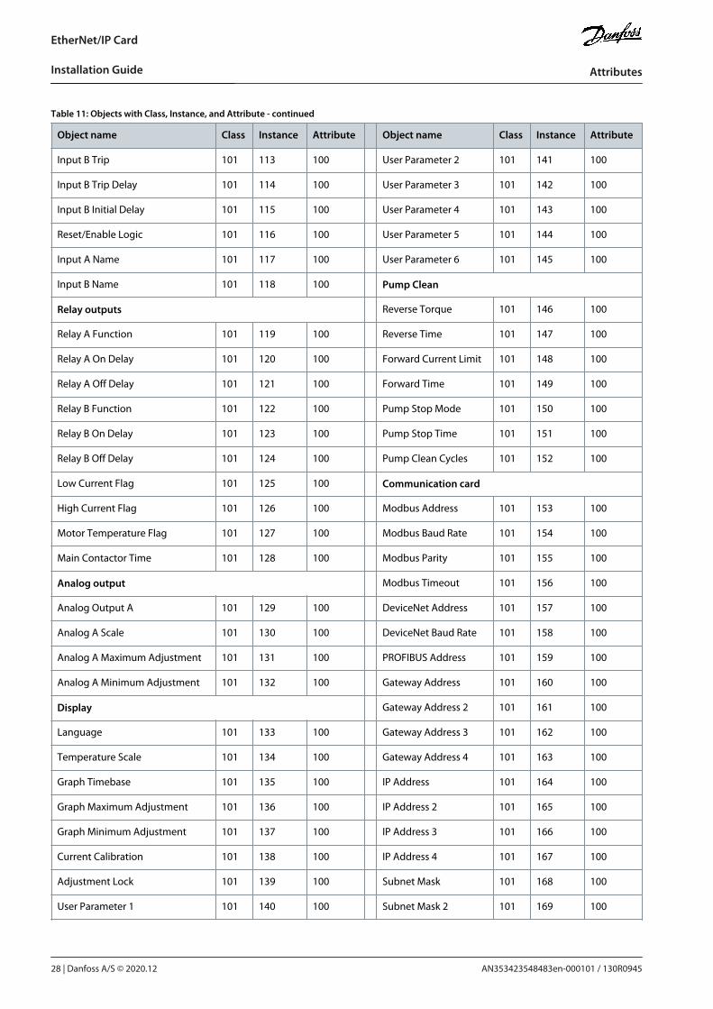
Table 11: Objects with Class, Instance, and Attribute - continued
Object name Class Instance Attribute Object name Class Instance Attribute
Input B Trip 101 113 100 User Parameter 2 101 141 100
Input B Trip Delay 101 114 100 User Parameter 3 101 142 100
Input B Initial Delay 101 115 100 User Parameter 4 101 143 100
Reset/Enable Logic 101 116 100 User Parameter 5 101 144 100
Input A Name 101 117 100 User Parameter 6 101 145 100
Input B Name 101 118 100 Pump Clean
Relay outputs Reverse Torque 101 146 100
Relay A Function 101 119 100 Reverse Time 101 147 100
Relay A On Delay 101 120 100 Forward Current Limit 101 148 100
Relay A Off Delay 101 121 100 Forward Time 101 149 100
Relay B Function 101 122 100 Pump Stop Mode 101 150 100
Relay B On Delay 101 123 100 Pump Stop Time 101 151 100
Relay B Off Delay 101 124 100 Pump Clean Cycles 101 152 100
Low Current Flag 101 125 100 Communication card
High Current Flag 101 126 100 Modbus Address 101 153 100
Motor Temperature Flag 101 127 100 Modbus Baud Rate 101 154 100
Main Contactor Time 101 128 100 Modbus Parity 101 155 100
Analog output Modbus Timeout 101 156 100
Analog Output A 101 129 100 DeviceNet Address 101 157 100
Analog A Scale 101 130 100 DeviceNet Baud Rate 101 158 100
Analog A Maximum Adjustment 101 131 100 PROFIBUS Address 101 159 100
Analog A Minimum Adjustment 101 132 100 Gateway Address 101 160 100
Display Gateway Address 2 101 161 100
Language 101 133 100 Gateway Address 3 101 162 100
Temperature Scale 101 134 100 Gateway Address 4 101 163 100
Graph Timebase 101 135 100 IP Address 101 164 100
Graph Maximum Adjustment 101 136 100 IP Address 2 101 165 100
Graph Minimum Adjustment 101 137 100 IP Address 3 101 166 100
Current Calibration 101 138 100 IP Address 4 101 167 100
Adjustment Lock 101 139 100 Subnet Mask 101 168 100
User Parameter 1 101 140 100 Subnet Mask 2 101 169 100
AN353423548483en-000101 / 130R094528 | Danfoss A/S © 2020.12
Attributes
EtherNet/IP Card
Installation Guide

Table 12: Objects with Class, Instance, and Attribute - continued
Object name Class Instance Attribute Object name Class Instance Attribute
Subnet Mask 3 101 170 100 Bypass Contactor Delay 101 176 100
Subnet Mask 4 101 171 100 Model Rating 101 177 100
DHCP 101 172 100 Screen Timeout 101 178 100
Location ID 101 173 100 Motor Connection 101 179 100
Advanced External Bypass 101 180 100
Tracking Gain 101 174 100 Shunt Trip Mode 101 181 100
Pedestal Detect 101 175 100 – – – –
AN353423548483en-000101 / 130R0945 | 29Danfoss A/S © 2020.12
Attributes
EtherNet/IP Card
Installation Guide
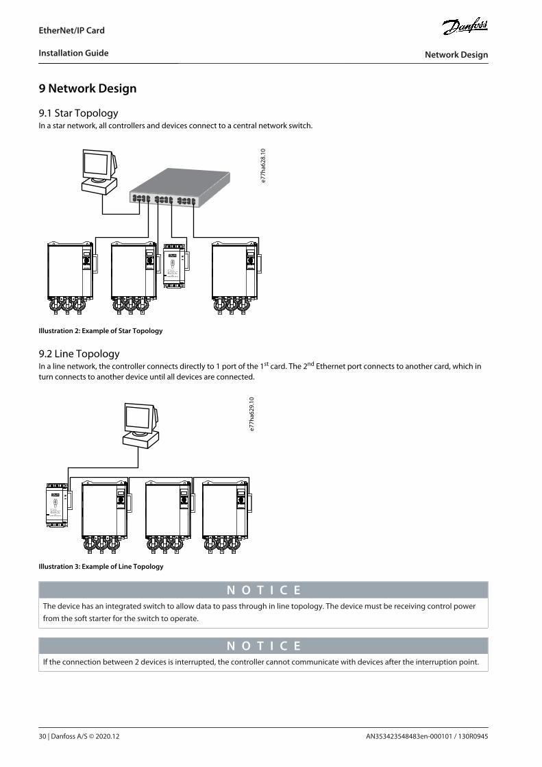
9 Network Design
9.1 Star TopologyIn a star network, all controllers and devices connect to a central network switch.
e77h
a628
.10
Illustration 2: Example of Star Topology
9.2 Line TopologyIn a line network, the controller connects directly to 1 port of the 1st card. The 2nd Ethernet port connects to another card, which inturn connects to another device until all devices are connected.
e77h
a629
.10
Illustration 3: Example of Line Topology
N O T I C EThe device has an integrated switch to allow data to pass through in line topology. The device must be receiving control powerfrom the soft starter for the switch to operate.
N O T I C EIf the connection between 2 devices is interrupted, the controller cannot communicate with devices after the interruption point.
AN353423548483en-000101 / 130R094530 | Danfoss A/S © 2020.12
Network Design
EtherNet/IP Card
Installation Guide

N O T I C EEach connection adds a delay to the communication with the next device. The maximum number of devices in a line network is32. Exceeding this number may reduce the reliability of the network.
9.3 Ring TopologyIn a ring topology network, the controller connects to the 1st card via a network switch. The 2nd Ethernet port of the card connectsto another device, which in turn connects to another device until all devices are connected. The final device connects back to theswitch.The device supports beacon-based ring node configuration.
e77h
a630
.10
Illustration 4: Example of Ring Topology
N O T I C EThe network switch must support loss of line detection.
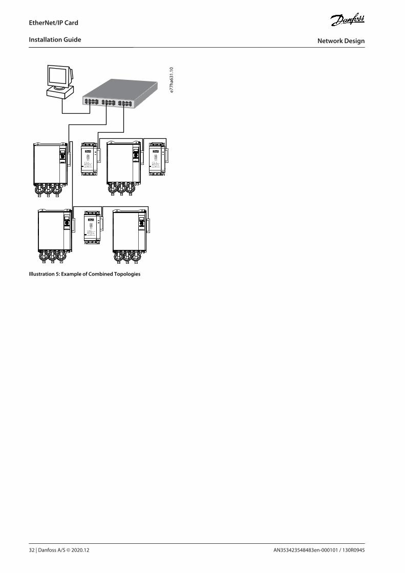
9.4 Combined TopologiesA single network can include both star and line components.
AN353423548483en-000101 / 130R0945 | 31Danfoss A/S © 2020.12
Network Design
EtherNet/IP Card
Installation Guide
e77h
a631
.10
Illustration 5: Example of Combined Topologies
AN353423548483en-000101 / 130R094532 | Danfoss A/S © 2020.12
Network Design
EtherNet/IP Card
Installation Guide
10 Specifications
10.1 ConnectionsSoft starter 6-way pin assembly
Contacts Gold flash
Network RJ45
10.2 SettingsIP address Automatically assigned, configurable
Device name Automatically assigned, configurable
10.3 NetworkLink speed 10 Mbps, 100 Mbps (auto-detect)
Full duplex
Auto crossover
10.4 PowerConsumption (steady state, maximum) 35 mA@24 V DC
Reverse polarity protected
Galvanically isolated
10.5 CertificationRCM IEC 60947-4-2
CE EN 60947-4-2
ODVA
Illustration 6: ODVA
AN353423548483en-000101 / 130R0945 | 33Danfoss A/S © 2020.12
Specifications
EtherNet/IP Card
Installation Guide

AN353423548483en-000101 / 130R0945
*M0025501*Danfoss A/S © 2020.12
Danfoss A/SUlsnaes 1DK-6300 Graastenvlt-drives.danfoss.com
Danfoss can accept no responsibility for possible errors in catalogs, brochures and other printed material. Danfoss reserves the right to alter its products without notice. Thisalso applies to products already on order provided that such alterations can be made without subsequential changes being necessary in specifications already agreed. Alltrademarks in this material are property of the respective companies. Danfoss and the Danfoss logotype are trademarks of Danfoss A/S. All rights reserved.
*130R0945*