installation guide - s3-ap-southeast-2.amazonaws.com · technical details fs65 a4265-2.3 hbm:...
TRANSCRIPT

Installation Guide
English
FS65Accelerometer

Hottinger Baldwin Messtechnik GmbH
Im Tiefen See 45
D-64239 Darmstadt
Tel. +49 6151 803-0
Fax +49 6151 803-9100
www.hbm.com
HBM FiberSensing, S.A.
Optical Business
Rua Vasconcelos Costa, 277
4470-640 Maia
Portugal
Tel. +351 229 613 010
Fax +351 229 613 020
www.hbm.com/fs
Mat.: 7-2002.4265
DVS: A4265-2.3 HBM: public
05.2015
Sensor Design Version: v1.0
� Hottinger Baldwin Messtechnik GmbH.
Subject to modifications.
All product descriptions are for general information only.
They are not to be understood as a guarantee of quality or
durability.

FS65 A4265-2.3 HBM: public 3
English
1 Technical Details 4. . . . . . . . . . . . . . . . . . . . . . . . . . . . . . . . . . . . . . . . .
1.1 General Information 4. . . . . . . . . . . . . . . . . . . . . . . . . . . . . . . . . . . . . . . .
1.1.1 Overview 4. . . . . . . . . . . . . . . . . . . . . . . . . . . . . . . . . . . . . . . . . . . . . . . . .
1.1.2 Characteristics 4. . . . . . . . . . . . . . . . . . . . . . . . . . . . . . . . . . . . . . . . . . . . .
1.1.3 Applications 5. . . . . . . . . . . . . . . . . . . . . . . . . . . . . . . . . . . . . . . . . . . . . . .
1.1.4 Quality 6. . . . . . . . . . . . . . . . . . . . . . . . . . . . . . . . . . . . . . . . . . . . . . . . . . .
1.1.5 Accessories 6. . . . . . . . . . . . . . . . . . . . . . . . . . . . . . . . . . . . . . . . . . . . . . .
1.2 General Specifications 7. . . . . . . . . . . . . . . . . . . . . . . . . . . . . . . . . . . . . .
2 Sensor Installation 8. . . . . . . . . . . . . . . . . . . . . . . . . . . . . . . . . . . . . . . .
2.1 Accelerometer 8. . . . . . . . . . . . . . . . . . . . . . . . . . . . . . . . . . . . . . . . . . . . .
2.1.1 List of Materials 8. . . . . . . . . . . . . . . . . . . . . . . . . . . . . . . . . . . . . . . . . . . .
2.1.2 Placing the Sensor 9. . . . . . . . . . . . . . . . . . . . . . . . . . . . . . . . . . . . . . . . .
2.1.3 Fixing the Sensor 10. . . . . . . . . . . . . . . . . . . . . . . . . . . . . . . . . . . . . . . . . .
2.1.4 Protecting the Sensor 10. . . . . . . . . . . . . . . . . . . . . . . . . . . . . . . . . . . . . . .
2.2 Bi or Triaxial Accelerometer 11. . . . . . . . . . . . . . . . . . . . . . . . . . . . . . . . .
2.2.1 List of Materials 11. . . . . . . . . . . . . . . . . . . . . . . . . . . . . . . . . . . . . . . . . . . .
2.2.2 Assembling the Sensors 12. . . . . . . . . . . . . . . . . . . . . . . . . . . . . . . . . . . .
2.2.3 Fixing the Assembly 20. . . . . . . . . . . . . . . . . . . . . . . . . . . . . . . . . . . . . . . .
2.2.4 Protecting the Sensors 20. . . . . . . . . . . . . . . . . . . . . . . . . . . . . . . . . . . . . .
3 Sensor Configuration 22. . . . . . . . . . . . . . . . . . . . . . . . . . . . . . . . . . . . .
3.1 Sensor Calibration Sheet 22. . . . . . . . . . . . . . . . . . . . . . . . . . . . . . . . . . . .
3.1.1 General nformation 23. . . . . . . . . . . . . . . . . . . . . . . . . . . . . . . . . . . . . . . . .
3.1.2 Calibration Data 23. . . . . . . . . . . . . . . . . . . . . . . . . . . . . . . . . . . . . . . . . . .
3.1.3 Acceleration Computation 23. . . . . . . . . . . . . . . . . . . . . . . . . . . . . . . . . . .

Technical Details
4 A4265-2.3 HBM: public FS65
1 Technical Details
1.1 General Information
This installation guide applies to the following products:
Part Number Description
K-FS65-30-11-302 FS65 - Accelerometer • Outdoor • FC/APC
K-FS65-30-13-302 FS65 - Accelerometer • Outdoor • SC/APC
K-FS65-30-10-302 FS65 - Accelerometer • Outdoor • NC
1.1.1 Overview
The FS65 - Accelerometer is a Fiber Bragg Grating
(FBG) based sensor, suitable for a large range of appli
cations where low frequency and small amplitude vibra
tions are present.
1.1.2 Characteristics
: Robustness
Long-term reliability ensured by innovative sensor
design, careful selection of materials and IP68 packag
ing.
: Completely passive
Inherent immunity to all electromagnetic effects (EMI,
RFI, sparks, etc.) and safe operation in hazardous envi
ronments.
Technical Details
FS65 A4265-2.3 HBM: public 5
: High multiplexing capability
Connection of a large number of sensors to a single opti
cal fiber, reducing network and installation complexity.
: Remote sensing
Large distance between sensors and interrogator (sev
eral kilometers).
: Compatible with most interrogators
Provided with calibration sheet, allowing easy and accu
rate configuration.
: Self-referenced
Based on the measurement of an absolute parameter -
the Bragg wavelength - independent of power fluctua
tions.
1.1.3 Applications
HBM FiberSensing accelerometer can be used in a large
range of monitoring applications, including measuring
ambient induced vibration of civil structures.
: Civil Engineering
: Energy
: R&D
Technical Details
6 A4265-2.3 HBM: public FS65
1.1.4 Quality
All HBM FiberSensing's processes are strictly controlledfrom development to production. Each product is sub
jected to high standard performance and endurance
tests, individually calibrated and checked before ship
ping.
HBM FiberSensing, S.A. concentrates all optical sensing
activity of HBM and is an ISO 9001:2008 certified com
pany.
1.1.5 Accessories
The implementation of complex sensing networks in large
structures is made simpler with HBM FiberSensing
accessories. These include cables especially designed to
resist harsh environments as in civil engineering, not onlyduring construction, but also during the lifetime of the
structure (humidity, corrosion, etc.).
HBM FiberSensing also provides accessories for compact in series mounting of two or three accelerometers in
transversal directions, allowing the simultaneous mea
surement of vibration along multiple axis.

Technical Details
FS65 A4265-2.3 HBM: public 7
1.2 General Specifications
Sensor
Sensitivity1) 75 pm/g @ 40 Hz
Measurement range ±10 g
Frequency range 0 to 50 Hz
Resonance frequency1) 430 Hz
Flatness < 2%
Resolution2)12.5 μg/�Hz
Maximum calib. error ±0.1 g @ 40 Hz
Transverse sensitivity < 0.1%
Optical
Central wavelength 1500 to 1600 nm
Spectral width (FWHM) < 0.2 nm
Reflectivity > 65%
Side lobe suppression > 10 dB
Inputs / Outputs
Cable type Ø 3 mm outdoor (armor)
Cable length 2 m each side (±5 cm)
Connectors FC/APC
SC/APC
NC (No Connectors)
Environmental
Operation temperature -20 to 80 ºC
Protection class IP68
Mechanical
Materials Aluminum
Dimensions 73 x Ø 53 mm
Weight 250 g
1) Typical values2) For 1 pm resolution in wavelength measurement

Sensor Installation
8 A4265-2.3 HBM: public FS65
2 Sensor Installation
2.1 Accelerometer
2.1.1 List of Materials
Included Material
Accelerometer
List of Needed Equipment
The needed tools to install the FS65 - Accelerometer
depend on the structure the sensor is to be installed on.
In many cases, mounting parts may need to be designed
in order to adapt the sensor to the spot where it is going
to be installed.
The installation solution should be carefully designed in
order to meet the sensor measuring direction and the
structure characteristics.

Sensor Installation
FS65 A4265-2.3 HBM: public 9
2.1.2 Placing the Sensor
The FS65 - Accelerometers can be placed headed up,headed down or towards the side (Fig. 2.1).
ÓÓÓÓÓÓÓÓÓÓÓÓÓÓÓÓÓÓÓÓÓÓÓÓÓÓÓÓÓÓÓÓÓÓÓÓÓÓÓÓ
ÔÔÔÔÔÔÔÔÔÔÔÔÔÔÔÔÔÔÔÔÔÔÔÔÔÔÔÔÔÔÔÔÔÔÔÔÔÔÔÔÔÔÔÔÔÔÔÔÔÔÔÔÔÔÔÔÔÔÔÔÔÔÔÔÔ
Fig. 2.1
Information
This will only alter the sensor's DC output. Dynamically, it
will still have the same behavior.
Its position must be set according to its measuring direc
tion.
Sensor Installation
10 A4265-2.3 HBM: public FS65
measuring
direction
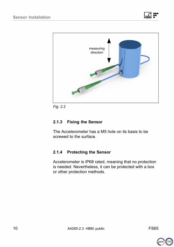
Fig. 2.2
2.1.3 Fixing the Sensor
The Accelerometer has a M5 hole on its basis to be
screwed to the surface.
2.1.4 Protecting the Sensor
Accelerometer is IP68 rated, meaning that no protection
is needed. Nevertheless, it can be protected with a box
or other protection methods.
Sensor Installation
FS65 A4265-2.3 HBM: public 11
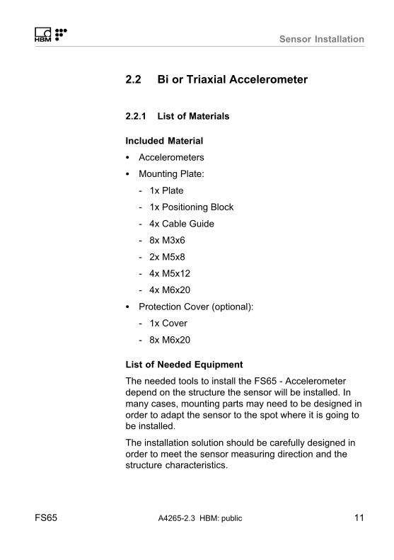
2.2 Bi or Triaxial Accelerometer
2.2.1 List of Materials
Included Material
� Accelerometers
� Mounting Plate:
- 1x Plate
- 1x Positioning Block
- 4x Cable Guide
- 8x M3x6
- 2x M5x8
- 4x M5x12
- 4x M6x20
� Protection Cover (optional):
- 1x Cover
- 8x M6x20
List of Needed Equipment
The needed tools to install the FS65 - Accelerometer
depend on the structure the sensor will be installed. In
many cases, mounting parts may need to be designed in
order to adapt the sensor to the spot where it is going tobe installed.
The installation solution should be carefully designed in
order to meet the sensor measuring direction and thestructure characteristics.
Sensor Installation
12 A4265-2.3 HBM: public FS65
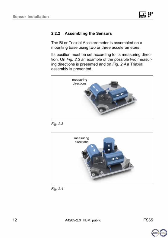
2.2.2 Assembling the Sensors
The Bi or Triaxial Accelerometer is assembled on amounting base using two or three accelerometers.
Its position must be set according to its measuring direc
tion. On Fig. 2.3 an example of the possible two measur
ing directions is presented and on Fig. 2.4 a Triaxialassembly is presented.
measuring
directions
Fig. 2.3
measuring
directions
Fig. 2.4

Sensor Installation
FS65 A4265-2.3 HBM: public 13
Preparing the Mounting Plate
Mechanical parts of the mounting plate are delivered
separately.
Start by screwing the position block to the mounting plate
using 3 of the provided M5x12 screws. These screws
should be threaded from the backside as shown on
Fig. 2.5.
Mounting plate
M5x12
Fig. 2.5
Position block
Fig. 2.6
Sensor Installation
14 A4265-2.3 HBM: public FS65
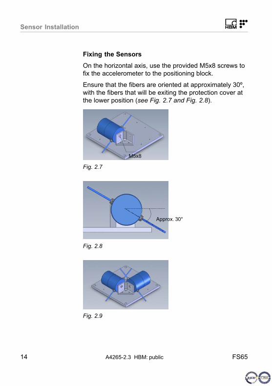
Fixing the Sensors
On the horizontal axis, use the provided M5x8 screws to
fix the accelerometer to the positioning block.
Ensure that the fibers are oriented at approximately 30º,
with the fibers that will be exiting the protection cover at
the lower position (see Fig. 2.7 and Fig. 2.8).
M5x8
Fig. 2.7
Approx. 30°
Fig. 2.8
Fig. 2.9

Sensor Installation
FS65 A4265-2.3 HBM: public 15
For the vertical axis sensor, use the remaining M5x12screw.
Place the vertical sensor with the fibers oriented at 45º
(Fig. 2.12).
M5x12
Fig. 2.10
Fig. 2.11
45°
Fig. 2.12

Sensor Installation
16 A4265-2.3 HBM: public FS65
Arranging Cables
Use the provided Cable Guides (Fig. 2.13) and M3x6
screws to place and fix the cable guides on the mounting
plate (Fig. 2.14).
Cable Guide
M3x6
Fig. 2.13
Fig. 2.14
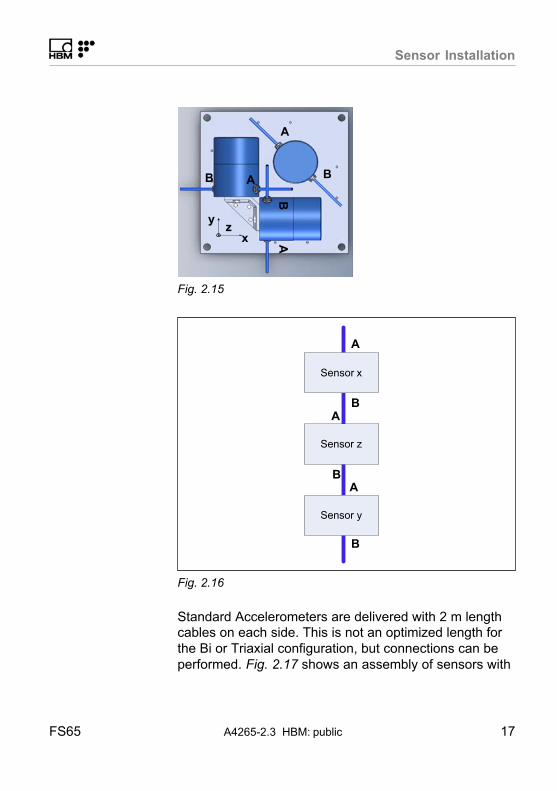
Considering the triaxial configuration and the defined
directions as represented on Fig. 2.15, sensor connec
tion should be performed as on Fig. 2.16:
Sensor Installation
FS65 A4265-2.3 HBM: public 17
y
xz
B A
AB
A
B
Fig. 2.15
A
BA
BA
B
Sensor x
Sensor y
Sensor z
Fig. 2.16
Standard Accelerometers are delivered with 2 m lengthcables on each side. This is not an optimized length for
the Bi or Triaxial configuration, but connections can be
performed. Fig. 2.17 shows an assembly of sensors with

Sensor Installation
18 A4265-2.3 HBM: public FS65
the standard cable lengths. In Fig. 2.18, an assembly ofsensors with an optimized cable length is presented.
Fig. 2.17
Fig. 2.18
Start by taking the cable B (Fig. 2.15) of the sensor on
the x axis and place it around the assembly as onFig. 2.19.
Then, take cable A of the sensor on the z axis and place
it around the assembly as on Fig. 2.20. Use an OpticalAdapter and attach both connectors.

Sensor Installation
FS65 A4265-2.3 HBM: public 19
ÖÖÖFig. 2.19
ÖÖÖÖÖÖÖÖÖÖÖÖÖÖÖÖÖÖÖÖÖÖÖÖÖÖÖÖÖÖÖÖÖÖÖÖÖÖÖÖÖÖÖÖÖÖÖÖÖÖÖÖÖÖÖÖÖÖÖÖÖÖÖÖÖÖÖÖÖÖÖÖÖÖÖÖÖÖÖÖÖ
ÖÇÇÖÖÇÇÇÇÇÇÇÇÖÖÖÖÖÖÖÖÇÇ
ÖÖÖFig. 2.20
ÖÖÖÖÖÖÖÖÖÖÖÖÖÖÖÖÖÖÖÖÖÖÖÖÖÖÖÖÖÖÖÖÖÖÖÖÖÖÖÖÖÖÖÖÖÖÖÖÖÖÖÖÖÖÖÖÖÖÖÖÖÖÖÖÖÖÖÖÖÖÖÖÖÖÖÖÖÖÖÖÖÖÖÖÖÖÖÖÖÖ
ÇÇÇÇÇÇÇÇÇÇÇÇÇÇÇÇÇÇÇÇÇÇÇÇÇÇÇÇÇÇÇÇÇÇÇÇÇÇÇÇÇÇÇÇÇÇÇÇÇÇÇÇÇÇÇÇÇÇÇÇÇÇÇÇÇÇÇÇÇÇÇÇÇÇÇÇÇÇÇÇÇÇÇÇÇÇÇÇÇÇ
ÖÖÖÖÇÇÇÇÖÖÖÖÇÇÖÖÇÇÖÇÇÇÖÖÖÖÇÇÇÇÖÖÖÖÇÇÖÖÇÇÇÇÖÖÖÖÇÖÖÖÇÇÇÇÖÖÖÖ
ÇÇÇÇÇÇÇÇÇÇÖÖÖÖÖÖÖÖÇÇÇÇ
ÖÖÖÖÇÇÇÇÇÇÖÖÖÖÖÖÖÖÇÇÇÇÇÇÇÇÇÇ
ÖÖÖFig. 2.21
ÇÇÇÇÇÇÇÇÇÇÇÇÇÇÇÇÇÇÇÇÇÇÇÇÇÇÇÇÇÇÇÇÇÇÇÇÇÇÇÇÇÇÇÇÇÇÇÇÇÇÇÇÇÇÇÇÇÇÇÇÇÇÇÇÇÇÇÇÇÇÇÇÇÇÇÇÇÇÇÇÇÇÇÇÇÇÇÇÇÇÇÇÇÇÇÇÇÇÇÇ
ÖÖÖÖÖÖÖÖÖÖÖÖÖÖÖÖÖÖÖÖÖÖÖÖÖÖÖÖÖÖÖÖÖÖÖÖÖÖÖÖÖÖÖÖÖÖÖÖÖÖÖÖÖÖÖÖÖÖÖÖÖÖÖÖÖÖÖÖÖÖÖÖÖÖÖÖÖÖÖÖÖÖÖÖÖÖÖÖÖÖÖÖÖÖÖÖÖÖÖÖ
ÇÇÇÇÇÇÇÇÇÇÇÇÇÇÇÇÇÇÇÇÇÇÇÇÇÇÇÇÇÇÇÇÇÇÇÇÇÇÇÇÇÇÇÇÇÇÇÇÇÇÇÇÇÇÇÇÇÇÇÇÇÇÇÇÇÇÇÇÇÇÇÇÇÇÇÇÇÇÇÇÇÇÇÇÇÇÇÇÇÇÇÇÇÇÇÇÇÇÇÇ
ÖÖÇÇÖÖÖÖÇÇÖÖÇÇÖÇÖÖÇÇÇÇÇÇÖÖÖÖÇÇÇÇÖÖÇÇÖÖÇÇÖÖÖÖÖÖÇÇÇÇÖÖÖÖÖÇÇÇÇÇÖÖÖÖ
ÇÇÇÇ
ÖÖÖÖÇÇÇÇÇÇÖÖÖÖ
ÇÇÇÇ
ÇÇ
ÖÖÖÖÖÖ
ÖÖÖÖÖÖÖÖÖÖÖÖÇÇÇÇÇÇÇÇÇÇÖÖÖÖ
ÇÇÇFig. 2.22
Proceed in a similar way with cable B of the z axis
accelerometer (Fig. 2.21) and cable A of the y axis
accelerometer (Fig. 2.22). Use clumps to fix cabling and
connections.
Sensor Installation
20 A4265-2.3 HBM: public FS65
2.2.3 Fixing the Assembly
The Bi or Triaxial assembly is now ready to be fixed tothe structure. The mounting base has 4 M6 holes for that
purpose. Four M6x20 screws are provided, but these can
be or not be suited for fixing the base to the structure.
The fixing method should be carefully defined.
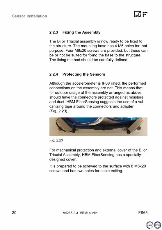
2.2.4 Protecting the Sensors
Although the accelerometer is IP68 rated, the performed
connections on the assembly are not. This means that
for outdoor usage of the assembly arranged as above
should have the connectors protected against moistureand dust. HBM FiberSensing suggests the use of a vul
canizing tape around the connectors and adapter
(Fig. 2.23).
Fig. 2.23
For mechanical protection and external cover of the Bi or
Triaxial Assembly, HBM FiberSensing has a specially
designed cover.
It is prepared to be screwed to the surface with 8 M6x20
screws and has two holes for cable exiting.

Sensor Installation
FS65 A4265-2.3 HBM: public 21
Fig. 2.24

Sensor Configuration
22 A4265-2.3 HBM: public FS65
3 Sensor Configuration
3.1 Sensor Calibration Sheet
Every HBM FiberSensing sensor is provided with a cali
bration sheet. The layout of this document is the samefor all accelerometers.
Fig. 3.1

Sensor Configuration
FS65 A4265-2.3 HBM: public 23
3.1.1 General nformation
Number 1 in Fig. 3.1 shows the general information on
the particular sensor, such as its type, the sensor part
number, its serial number and the production tracking
number, the FBG ID.
3.1.2 Calibration Data
The most important information related to the accelerom
eter sensor – the two central wavelengths at room temperature and sensitivity - is shown in the Calibration Data
table (number 2 in Fig. 3.1). These values should be
used for acceleration computation.
3.1.3 Acceleration Computation
Number 3 in Fig. 3.1 exemplifies the calculations that
should be performed for wavelength measurement to
acceleration conversion. The acceleration variation of an
Accelerometer, under a reference frequency, is given by
the quotient of wavelength shift from the zero moment bythe sensor's sensitivity.
acceleration � x�S � acceleration
� (WL � CWL)�S
Fig. 3.2
Where
� x is the wavelength shift in nm
� S is the given sensitivity in nm/g
� CWL is the central wavelength of the sensor at the
zero moment in nm
� WL is the measured wavelength in nm.

ww
w.h
bm
.co
m
HBM Test and Measurement
Tel. +49 6151 803-0
Fax +49 6151 803-9100
measure and predict with confidence
A4265-2
.3 7-2
002.4
265 H
BM
: public