installation guide - slb - l - american...
TRANSCRIPT

INSTALLATION GUIDEThis product is covered by U.S. Patent #5906084 and other patents pending.
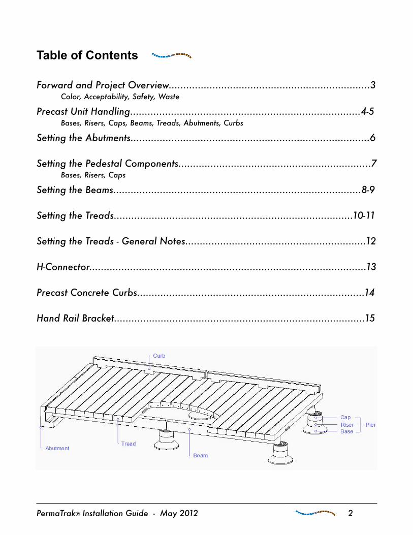
Table of Contents
Forward and Project Overview.....................................................................3 Color, Acceptability, Safety, Waste
Precast Unit Handling...............................................................................4-5 Bases, Risers, Caps, Beams, Treads, Abutments, Curbs
Setting the Abutments..................................................................................6
Setting the Pedestal Components..................................................................7 Bases, Risers, Caps
Setting the Beams.....................................................................................8-9
Setting the Treads..................................................................................10-11
Setting the Treads - General Notes..............................................................12
H-Connector...............................................................................................13
Precast Concrete Curbs..............................................................................14
Hand Rail Bracket......................................................................................15
PermaTrak® Installation Guide - May 2012 2

Forward
This installation guide is to be used as a reference only. The construction of the PermaTrak® system may vary from information contained in this guide due to different field conditions, special components, or other construction requirements. Please contact your PermaTrak field representative with any questions regarding installation details or product features.
Color
• Colors may vary due to the materials used. Variations in sand, aggregate, and cement can cause slight differences in the finished color of precast components. An exact duplicate cannot be guaranteed.
Acceptability
• All PermaTrak® components are produced in National Precast Concrete Association certified production facilities. The precast components meet or exceed NPCA or PCI guidelines. Every effort is used to deliver the best product possible.
• Imperfections in concrete are inevitable. Small bug holes on the surface are not detrimental to the structural integrity or durability of the PermaTrak components.
Safety
• All safety codes and construction guidelines for handling heavy material should be closely followed. Those working at the job site should comply with all health, safety, and environmental policies.
Waste
• Ensure that all waste is removed from site and responsibly discarded.
PermaTrak® Installation Guide - May 2012 3

Precast Unit Handling
All lifting equipment that comes in contact with the precast components should have rubber padding installed for protection. We recommend that adequate padding be used on both the top and bottom of the handling forks. This is an important step that will help prevent damage to the component surfaces.
Bases, Risers and Caps
• Each of these standard components has a threaded lifting insert cast into the top of the unit. Refer to the shop drawings for specific sizes of threaded lifting inserts.
• Using a threaded rod with a hook bend or an eye bolt (provided by contractor) is recommended for handling.
Beams
• Each beam is produced with two threaded lifting inserts on the top surface. Refer to the shop drawings for specific sizes of threaded lifting inserts. Beams may be handled by proper lifting equipment using eye bolts in these inserts.
PermaTrak® Installation Guide - May 2012 4
• Slings and equipment with forks may also be used if they are placed at the proper lifting points.
• Beams may be damaged if they are lifted with incorrectly placed slings or forks. Please consult your PermaTrak representative with questions about handling the beams.

Treads
• Maintaining the proper physical appearance of the tread surface ensures an acceptable installation.
•To remove individual treads from delivered stack, two lifting straps should be used. Position straps toward the outer edges of the tread. Never lift treads in the center, as this action may cause damage to the tread. If forks are to be used, they must be positioned to pick up the treads on the outer quarters of the tread’s total length. A 12 ft. long tread should have a fork spread of 6 ft. minimum.
•After the tread is installed, the top surface must be protected from abrasion or wear caused by wheels, tracks, or construction material. Always protect the tread surface with plywood or OSB sheeting.
• Consult with your PermaTrak® representative for special requirements if the boardwalk is to be constructed “top-down.” Your representative will advise on handling equipment and techniques applicable to your project.
Abutments• The abutments have two threaded lifting
inserts on the inner wall for handling. Refer to the shop drawings for specific sizes of threaded lifting inserts.
Curbs• The curbs can be removed from the pallet or
stack using slings at each end.
PermaTrak® Installation Guide - May 2012 5
Setting the Abutments Abutments
• Place abutments on prepared subgrade, specified in the installation drawings. A chalk line placed on the subgrade is recommended for aligning abutments.
• Clean debris from the prepared subgrade and abutments. There should be minimal gap between the units (less than 1/4”).
H-Connectors for Abutment-to-Abutment Connection
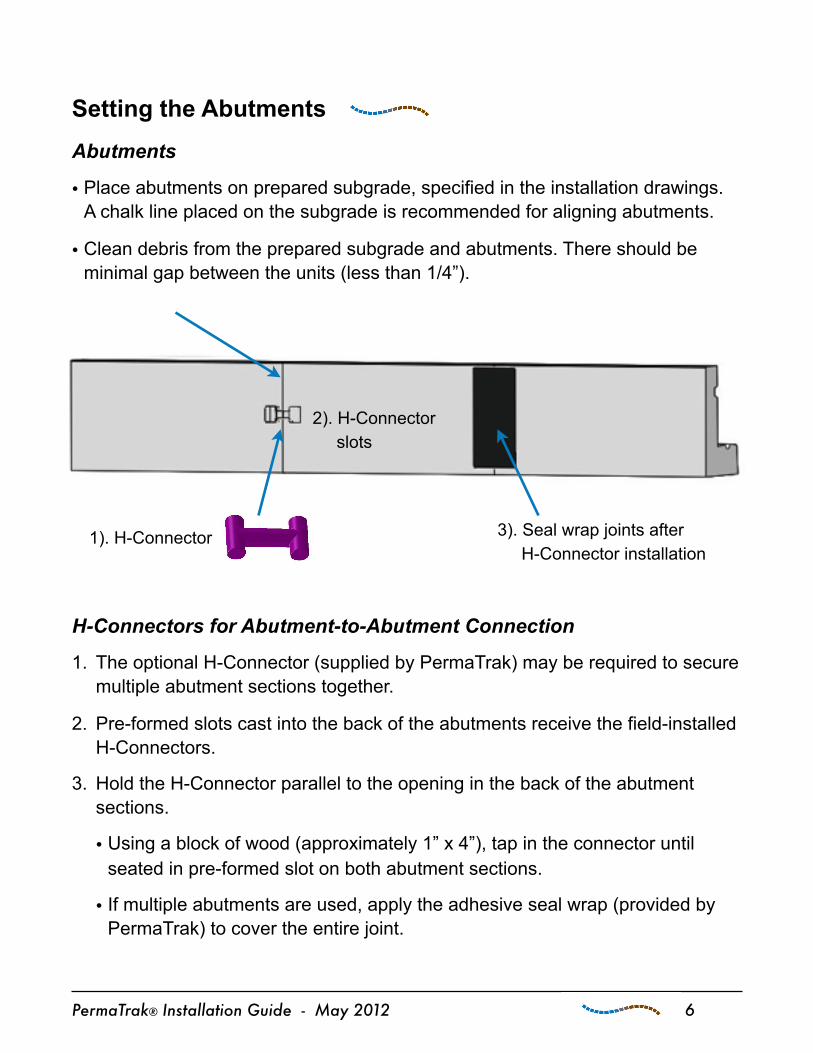
1. The optional H-Connector (supplied by PermaTrak) may be required to secure multiple abutment sections together.
2. Pre-formed slots cast into the back of the abutments receive the field-installed H-Connectors.
3. Hold the H-Connector parallel to the opening in the back of the abutment sections.
• Using a block of wood (approximately 1” x 4”), tap in the connector until seated in pre-formed slot on both abutment sections.
• If multiple abutments are used, apply the adhesive seal wrap (provided by PermaTrak) to cover the entire joint.
PermaTrak® Installation Guide - May 2012 6
1). H-Connector
2). H-Connector slots
3). Seal wrap joints after H-Connector installation
Setting the Pedestal Components Laser levels are recommended to ensure accurate elevations throughout the installation process.
Bases
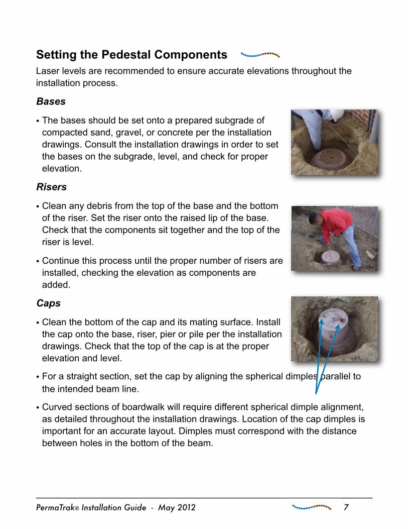
• The bases should be set onto a prepared subgrade of compacted sand, gravel, or concrete per the installation drawings. Consult the installation drawings in order to set the bases on the subgrade, level, and check for proper elevation.
Risers
• Clean any debris from the top of the base and the bottom of the riser. Set the riser onto the raised lip of the base. Check that the components sit together and the top of the riser is level.
• Continue this process until the proper number of risers are installed, checking the elevation as components are added.
Caps
• Clean the bottom of the cap and its mating surface. Install the cap onto the base, riser, pier or pile per the installation drawings. Check that the top of the cap is at the proper elevation and level.
• For a straight section, set the cap by aligning the spherical dimples parallel to the intended beam line.
• Curved sections of boardwalk will require different spherical dimple alignment, as detailed throughout the installation drawings. Location of the cap dimples is important for an accurate layout. Dimples must correspond with the distance between holes in the bottom of the beam.
PermaTrak® Installation Guide - May 2012 7

Setting the Beams• We recommend lifting the beams with eye bolts in the threaded lifting inserts on
the beam’s top surface.
• On the bottom surface of each beam there are two pre-formed holes, one round and one elongated oval. These holes are to receive the spherical connecting pins (provided by PermaTrak).
Round hole (this end 1st) Elongated oval hole (this end 2nd)
• While the beams are suspended in air, the spherical connector can be tapped into the round, pre-formed hole on the bottom surface of the beam (see photo-bottom right).
• Silicone spray lubricant can be used to aid placement of this spherical connector into the round, pre-formed hole. The sphere should rest flush with the bottom surface of the beam.
PermaTrak® Installation Guide - May 2012 8
Beam Bottom View
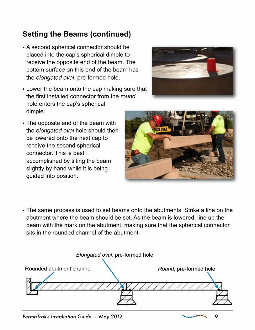
Setting the Beams (continued)• A second spherical connector should be
placed into the cap’s spherical dimple to receive the opposite end of the beam. The bottom surface on this end of the beam has the elongated oval, pre-formed hole.
• Lower the beam onto the cap making sure that the first installed connector from the round hole enters the cap’s spherical dimple.
• The opposite end of the beam with the elongated oval hole should then be lowered onto the next cap to receive the second spherical connector. This is best accomplished by tilting the beam slightly by hand while it is being guided into position.
• The same process is used to set beams onto the abutments. Strike a line on the abutment where the beam should be set. As the beam is lowered, line up the beam with the mark on the abutment, making sure that the spherical connector sits in the rounded channel of the abutment.
PermaTrak® Installation Guide - May 2012 9
Elongated oval, pre-formed hole
Round, pre-formed hole Rounded abutment channel
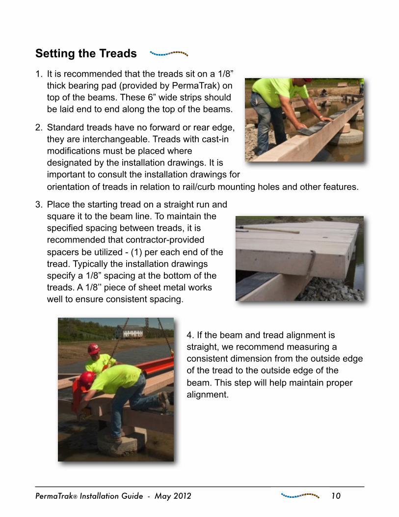
Setting the Treads 1. It is recommended that the treads sit on a 1/8”
thick bearing pad (provided by PermaTrak) on top of the beams. These 6” wide strips should be laid end to end along the top of the beams.
2. Standard treads have no forward or rear edge, they are interchangeable. Treads with cast-in modifications must be placed where designated by the installation drawings. It is important to consult the installation drawings for orientation of treads in relation to rail/curb mounting holes and other features.
3. Place the starting tread on a straight run and square it to the beam line. To maintain the specified spacing between treads, it is recommended that contractor-provided spacers be utilized - (1) per each end of the tread. Typically the installation drawings specify a 1/8” spacing at the bottom of the treads. A 1/8’’ piece of sheet metal works well to ensure consistent spacing.
4. If the beam and tread alignment is straight, we recommend measuring a consistent dimension from the outside edge of the tread to the outside edge of the beam. This step will help maintain proper alignment.
PermaTrak® Installation Guide - May 2012 10

Setting the Treads (continued) 5. The treads may have
provisions for a urethane stop pin (provided by PermaTrak), usually placed every 4-5 treads. Install the tapered end of the urethane pin into the tapered holes on the bottom surface of the tread. These pins require no lubricant and should be tapped in until they are snug.
6. We recommend checking the linear measurements to the end abutment as tread installation continues. It is much easier to adjust tread spacing (if needed) as you proceed, rather than to return and move previously installed treads. It is recommended to check this linear measurement every 4-5 treads.
7. When treads are less than 7’-6’’ wide and can be easily handled, temporarily set the last several treads with no spacing, prior to meeting the abutment. This will allow for a simple placement of the final tread into the keyway of the abutment. Once the final tread is placed, the previously unspaced treads can then be set uniformly.
8. When treads are over 7’-6’’ wide or over 700 lbs., it is optional to remove the tongue on the final tread that adjoins the abutment. An alternative to this method is to support the end beams adjacent to the abutment on temporary wood supports. These temporary blocks should be stacked just high enough to move the abutments away from the beams, install the final tread, then move the abutments back into final location. Then lift the beams with a pry bar to remove the wood blocks and set the beam back down onto the abutment.
PermaTrak® Installation Guide - May 2012 11
Setting the Treads - General Notes Handling Larger Treads
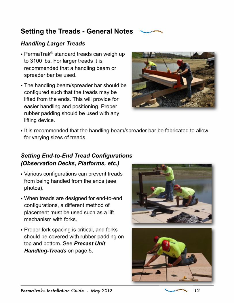
• PermaTrak® standard treads can weigh up to 3100 lbs. For larger treads it is recommended that a handling beam or spreader bar be used.
• The handling beam/spreader bar should be configured such that the treads may be lifted from the ends. This will provide for easier handling and positioning. Proper rubber padding should be used with any lifting device.
• It is recommended that the handling beam/spreader bar be fabricated to allow for varying sizes of treads.
Setting End-to-End Tread Configurations (Observation Decks, Platforms, etc.)
• Various configurations can prevent treads from being handled from the ends (see photos).
• When treads are designed for end-to-end configurations, a different method of placement must be used such as a lift mechanism with forks.
• Proper fork spacing is critical, and forks should be covered with rubber padding on top and bottom. See Precast Unit Handling-Treads on page 5.
PermaTrak® Installation Guide - May 2012 12

H-Connector(Patent Pending)
Tread-to-Beam Connection for Uplift Resistance
• The optional H-Connector (supplied by PermaTrak) is used to attach the treads to the beams per the installation drawings.
• The pre-formed slots cast into the beam and the tread receive the field-installed H-Connector.
• Fully insert the H-Connector until it seats itself into the pre-formed slot in the tread.
• Position the H-Connector installation tool (supplied by PermaTrak) in the same pre-formed slot (see left photo).
• Apply pressure to the installation tool handle until the H-Connector snaps into the beam’s pre-formed slot.
PermaTrak® Installation Guide - May 2012 13
Apply pressure until H-Connector is fully seated
Tread Recess
Beam Recess
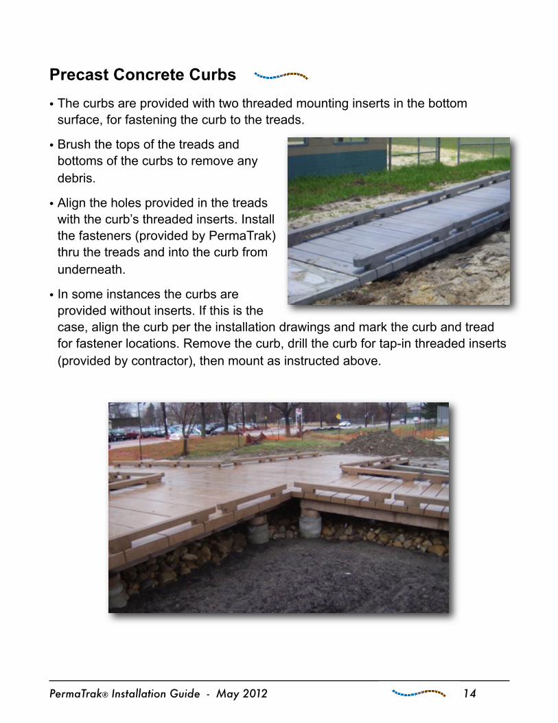
Precast Concrete Curbs• The curbs are provided with two threaded mounting inserts in the bottom
surface, for fastening the curb to the treads.
• Brush the tops of the treads and bottoms of the curbs to remove any debris.
• Align the holes provided in the treads with the curb’s threaded inserts. Install the fasteners (provided by PermaTrak) thru the treads and into the curb from underneath.
• In some instances the curbs are provided without inserts. If this is the case, align the curb per the installation drawings and mark the curb and tread for fastener locations. Remove the curb, drill the curb for tap-in threaded inserts (provided by contractor), then mount as instructed above.
PermaTrak® Installation Guide - May 2012 14

Hand Rail Bracket(Patent Pending)
• Handrail brackets and corresponding fasteners (all supplied by PermaTrak) are optional components. If specified, they are fastened to the treads at locations designated in the installation drawings.
• The closed part of the bracket should be facing the center of the walkway (see photo below).
• Place the timber posts into the bracket and mark location of the holes. Prior to drilling the holes thru the post, remove the post from the mounting bracket.
• Do not drill thru the bracket - this will remove the corrosion-resistant properties of the plating on the bracket.
• Bolt the post into position using the post mounting hardware (provided by PermaTrak).
• The same mounting techniques for the bracket shown can be utilized for a variety of hand rail and curb rail designs. Different styles of hand rails and curbs will incorporate a fastener system similar to the design illustrated above.
PermaTrak® Installation Guide - May 2012 15