installation guide...starter strip to each other. starter can be cut with tin snips when shorter...
TRANSCRIPT
Installation Guide
2
Table of Contents
Siding Profiles _________________3
Accessories ____________________4
Tools & Equipment _____________5
Preparation ___________________6
House Insulation and House Wrap ______6
Surface Preparation __________________6
Window Sill Preparation ______________6
Window and Door Build Out ___________6
Undersill and Undereave Furring ________7
Straightline _________________________7
Level _____________________________7
Accessory Installation __________8
Inside Corners ______________________8
Expansion for Inside Corners ___________8
Outside Corner Post (O.C.P.) ___________8
O.C.P. Installation ___________________8
Steel Starter Strip ____________________9
Nailing ___________________________9
Other Starter Methods ________________9
Window and Door J-Channel Use ______10
Flashing __________________________10
Gable Sidewall J-Channel Use _________10
Steel Siding Cutting ___________11
Power Saw ________________________11
Tin Snips _________________________11
Cut-off Tool _______________________11
Electric Shear ______________________11
Panel Installation _____________12
Row 1 ___________________________12 Panel Laps ________________________12 Expansion and Contraction ___________12 Proper Siding Staggering _____________12 Hanging of Siding __________________13 Nails ____________________________13 Power Nailers _____________________13 Panels at Window (Bottoms) __________13 Panels at Windows and Doors (Tops) ____14 Furring ___________________________14 Finishing __________________________14
Gable End Measuring and Cutting _____14Installing ______________________14 Final Row of Siding Under Eaves ____15
Board and Batten Only Application ____15Accessories and Starter ___________15 First Row ______________________15 Subsequent Rows _______________15 Door and Window Cuts __________15
Clean Up _________________________16 Job Site __________________________16 Replacing Damaged Panels ___________16Additional Tips _____________________16

3
Double 4” HorizontalA four-inch profile gives the exterior a more “solid” appearance and therefore draws the eye to the accents, window and door trim especially.
6 Siding Profiles
Single 6” HorizontalA six-inch profile provides homeowners with a new option not available in vinyl. Reflecting the charm of traditional siding, the look of our six-inch profile offers a distinctive architectural expression.
Single 6” Dutch Lap HorizontalA six-inch profile with a groove at the top of each panel to improve strength and reflect light, adding visual interest and natural shadow lines.
Single 8” HorizontalThe eight-inch profile is an architectural statement. It tends to call attention to itself. Therefore the window and door trim should blend in with the siding, rather than creating a strong contrast.
Board & Batten Profiles - 6” & 10”Board and batten provides greater design options for the exterior. It comes in 19 designer colors and offers both a narrow or wide option. The unique profile makes it a great accent for certain styles of homes or combine the two patterns for a custom look.
7”6.13”
8.75” 8” 7”6.13”
8.75”8”
3/4”
7.88”
6”
3/4”
11.88”
10”
(6” Profile)
(10” Profile)
4
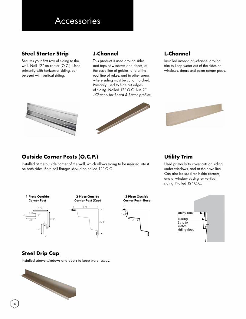
Steel Starter StripSecures your first row of siding to the wall. Nail 12” on center (O.C.). Used primarily with horizontal siding, can be used with vertical siding.
Steel Drip CapInstalled above windows and doors to keep water away.
Accessories
J-ChannelThis product is used around sides and tops of windows and doors, at the eave line of gables, and at the roof line of rakes, and in other areas where siding must be cut or notched. Primarily used to hide cut edges of siding. Nailed 12” O.C. Use 1” J-Channel for Board & Batten profiles.
L-ChannelInstalled instead of j-channel around trim to keep water out of the sides of windows, doors and some corner posts.
Outside Corner Posts (O.C.P.)Installed at the outside corner of the wall, which allows siding to be inserted into it on both sides. Both nail flanges should be nailed 12” O.C.
Utility TrimUsed primarily to cover cuts on siding under windows, and at the eave line. Can also be used for inside corners, and at window casing for vertical siding. Nailed 12” O.C.
3.75”
.25”
3.75”
1.25”
1.25”
.69”
.69”
.25”
.5”
.5”
1-Piece Outside Corner Post
3.75”.5”
.5”
3.75”
2-Piece Outside Corner Post (Cap)
2-Piece Outside Corner Post - Base
2”
1.44”
.65”

5
Tools & Equipment
ToolsHelpful Tools for Installation�� Hammer �� Level �� Tape Measure�� Power Saw (with steel sheet metal blade) �� Electric Shear �� Utility Knife �� Safety Goggles �� Aviation Snip �� Flathead Screwdriver �� Caulk Gun�� Speed Square�� Needles Nose Pliers
Additional Tools for Installation�� Trim Coil �� Touch-up Paint�� 1 1/2” to 2 1/2” Galvanized Siding Nails �� 1” to 1 3/4” Steel Trim Nails�� Nail Punch�� Butyl or erathane based caulk
Ladders and ScaffoldsMany different styles and options are available. Most common system used by siding professionals are extension ladders and ladder jacks, simply because of there portability and minimal cost. Contact your local OSHA office for specifications on proper scaffolding for your particular need.
EquipmentSiding Cutting TableThis table allows for a normal circular saw to be used with the proper steel blade to cut siding and soffit, especially helpful for angled cuts on peaks and rakes. These tables are lightweight and portable and can be set up and moved by one person with ease. These tables also allow for the saw to be away from the siding when being cut. This allows for fewer scratches or damage to occur to the siding panels.
*Always make sure to wear protective safety glasses and gloves when cutting/handling steel siding.
*Follow safety instructions that accompany your tools/blades and wear the suggested protective gear.
6
Preparation
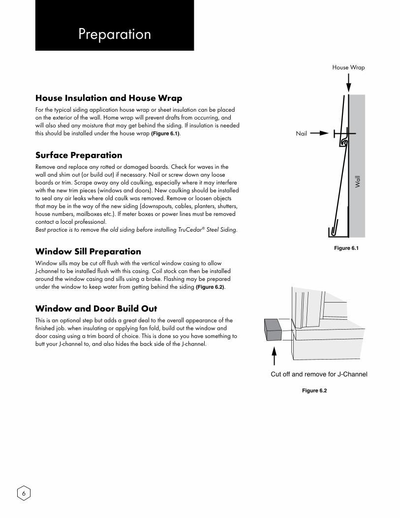
House Insulation and House Wrap For the typical siding application house wrap or sheet insulation can be placed on the exterior of the wall. Home wrap will prevent drafts from occurring, and will also shed any moisture that may get behind the siding. If insulation is needed this should be installed under the house wrap (Figure 6.1).
Surface PreparationRemove and replace any rotted or damaged boards. Check for waves in the wall and shim out (or build out) if necessary. Nail or screw down any loose boards or trim. Scrape away any old caulking, especially where it may interfere with the new trim pieces (windows and doors). New caulking should be installed to seal any air leaks where old caulk was removed. Remove or loosen objects that may be in the way of the new siding (downspouts, cables, planters, shutters, house numbers, mailboxes etc.). If meter boxes or power lines must be removed contact a local professional. Best practice is to remove the old siding before installing TruCedar® Steel Siding.
Window Sill PreparationWindow sills may be cut off flush with the vertical window casing to allow J-channel to be installed flush with this casing. Coil stock can then be installed around the window casing and sills using a brake. Flashing may be prepared under the window to keep water from getting behind the siding (Figure 6.2).
Window and Door Build OutThis is an optional step but adds a great deal to the overall appearance of the finished job. when insulating or applying fan fold, build out the window and door casing using a trim board of choice. This is done so you have something to butt your J-channel to, and also hides the back side of the J-channel.
Nail
Wal
l
House Wrap
Figure 6.1
Figure 6.2
Cut off and remove for J-Channel

7
Undersill and Undereave FurringUndersill and undereave furring is often needed when the row of siding needs to be cut down to fit under the window sill or to fit under the eaves. Furring is installed in these situations to maintain the proper slope angle of the siding across the face of the panel. These cuts are then covered with finish trim.
StraightlineA chalk line is a good way to start an installation. Often times this is used to develop a reference line as to which the starter strip can be installed. We recommend measuring equal distances down from the eave line, or from the window sills that are at the same height (Figure 7.1). This line allows for the siding to be run parallel with the eaves or windows which gives the appearance that the siding is running level regardless of the actual levelness of the house or ground.
LevelAnother good way to start an installation is to check if the walls are level. If the walls are reasonably level a chalk line and level may be used to determine a line for the starter strip to be installed. This is done by driving a nail at the desired height for the top of the starter strip. Connect the end of the chalk line to the nail and pull to the opposite end of the wall, make sure to pull the line tight. Then use a level in the middle of the line to determine where the chalk line should be snapped. Be sure there is no sag in the line when it is snapped, this can easily occur when the line is stretched over 20’. Continue this process on all sides of the building making sure the line matches up on all sides. This is very important because this is the basis for all subsequent rows of siding.
*It is recommended to use a level 4’ or longer in this process and also to take level readings at the center of the line.
Figure 7.1

8
Inside CornersTwo J-channels at right angles may be used for the inside corners (Figure 8.1). Install a small bead of caulking where the two J-channels meet one another (Figure 8.2). J-channels should be installed at full lengths, 1/2” below the bottom of the starter strip and extending to the eave line or gable trim. If a shorter piece is needed to reach the eave or gable trim be sure to overlap the bottom piece with the top piece. J-channel flanges should be nailed every 12”, making sure not to drive the nails to tight. Driving nails to tight may cause a distortion to occur in the J-channel. J-channels can easily be cut with a pair of aviation snips.
Accessory Installation
Figure 8.2
Figure 8.1
Expansion for Inside CornersSiding is installed into the receiving end of the J-channel, making sure to leave 1/16” of space between the back side of the J-channel and siding.

9
Steel Starter StripUsing your chalk line previously established, install top of starter strip on the line. Be sure to build out any hollow spots behind starter strip to prevent any wavy appearances in bottom row of siding. Make sure starter strip is straight and meets accurately at all corners of building. If using starter strip for vertical siding be sure to use a plumb line to determine where starter should be nailed.
Nailing Be sure to install starter with nails spaced no more than 12” O.C. (Figure 9.4). Overlap the corner nail flanges (inside & outside), this will help reduce any air leaks. Be sure to nail starter strip as low as possible this will provide extra rigidity to bottom row of siding. Do not overdrive nails to prevent distortion. Butt starter strip to each other. Starter can be cut with tin snips when shorter lengths are needed.
Other Starter MethodsStarter strip may not work in all situations, often times J-channel may be used to start rows of siding especially over decks, concrete porches, brick, retaining walls, garage doors etc.
Top view of One Piece Corner Post
Figure 9.1
Figure 9.2
Figure 9.3
(Figure 9.4)
Outside Corner Post (O.C.P.)The bottom of the O.C.P. can be capped by cutting away the J-portion of corner and folding the remaining faces of corner back to close the bottom of corner (Figure 9.1). Tops of corners may be capped in the same fashion. These steps apply to both one and two piece O.C.P. Corner posts should be installed prior to the siding panels.
One Piece O.C.P. InstallationThe O.C.P. is installed in the same manner as the inside corners, 1/2” below the bottom of the starter strip and running to the eave line or gable trim. If more than one post is needed to reach the desired height be sure to overlap bottom corner with the top corner. Be sure to install nails every 12” on both nail flanges. Avoid driving nails to tight because distortion can occur if this is done. Make sure corners are installed squarely to the wall, this will add to the final appearance of the job.
Two Piece O.C.P. Installation (Figure 9.3)
The Two Piece O.C.P. base is installed first, before the cap is attached. Fasten the base to the building plumb to the corner, ½” below the bottom of the starter strip. This can be done with a plumb line as a level. If more than one post is needed to reach the desired height be sure to overlap bottom corner with top corner. Be sure to install nails every 12” on both nailing areas. Avoid driving nails to tight because distortion can occur if this is done. Make sure the corner base is installed squarely to the wall, this will add to the final appearance of the job. Once the base is installed, cut and your siding to fit tightly into the pocket and then add the cap to finish it off. Attach one side of the cap to the base along the full length, and then work the other side in. No nails are needed to install the cap.
3.75”.5”
.5”
3.75”
2-Piece Outside Corner Post (Cap)

10
Window and Door J-Channel UseJ-channel can be installed around windows and doors (Figure 10.1). This is done so the butt end of the siding can be slipped into the J-channel opening. The side pieces of J-channel are left 3/4” above the window top, and 3/4” below the window sill. The bottom of the J-channel has a V-groove notched out of the back side and nail flanges (3/4” depth). This allows for the siding to slip into the finish trim and hide the cut of the finish trim. The top of the J-channel has the back side notched out 3/4”, leaving the face and nail flange in place. The top J-channel is cut to fit from outside to outside of the side J-channels. A 3/4” slit is cut into the corners of the J-channel and top is folded down inside the side J-channel pocket. Be sure to put the face of top J-channel over the face of the side J-channel. Drip cap needs to be installed before the J-channel at the top of the windows and doors. L-channel should be used in this application.
FlashingIt is a good idea to install window tape over existing window nail flange (Figure 10.2). Also you may install a piece of window tape or coil stock under the nail flange of the side J-channels and lap over the nail flange of the siding panel directly under the window or opening. This will allow water to run over the top of the siding and out the weep holes in the bottom of the siding instead of behind the siding panel.
Gable Sidewall J-Channel UsePrior to siding installation a J-channel may be placed at the bottom of the sidewall. This allows cut ends of siding to be hidden. Start J-channel at bottom of gable sidewall and work to the top of the gable. Be sure to overlap bottom J-channel with top J-channel if more than one piece is needed to reach top. (Figure 10.3 and 10.4) At the top of the gable butt one J-channel into the peak and overlap this J-channel with the other side J-channel. Nail every 16”.
Examples of Finished J-Channel
Figure 10.1
Figure 10.2
Figure 10.3 Figure 10.4

11
1. Power SawSteel siding may be cut with a carbide tip saw blade, that is specifically designed for cutting steel. Always cut the siding with the painted finish down. Failure to do this may damage the protective finish applied to the siding and void the warranty.
2. Tin SnipsA tin snips may be used to cut siding (Figure 11.1). Start by drawing a straight line on the siding with a speed square. Start cutting with the lock edge first working downward, cut through middle butt carefully, continue downward, snip through and around the bottom lock. Then use a screwdriver to re-open the lock edge and bottom locking edge. Also used to cut J-channel, finish trim, and O.C.P.
3. Cut-off ToolA guillotine siding cutter may be used for straight cuts (Figure 11.2). These tools have interchangeable blades designed for 4”, 6”, and 8” siding.
4. Electric ShearThis tool may be used for length wise cuts across face of siding. Especially helpful for window and door cuts.
Steel Siding Cutting
Figure 11.1
Figure 11.2

12
Panel Installation
Row OneRow one is the most important row of siding on the building. This row is the basis for all other rows of siding to be installed. Make sure this row runs parallel to the eaves and or windows, or is level depending on the situation (Figure 12.1). Install bottom lock of siding around bottom edge of starter strip, be sure that entire bottom lock of siding is around the bottom of starter. Be sure not to pull to hard on this row when nailing, if forced to hard a distortion of the panel may occur. Check for alignment of inside and outside corners making sure panel matches up at all corners. You should have a minimum of 6” clearance between ground and bottom of the first row. Install end of siding into corner post openings first, then apply upward pressure down the entire piece of siding, making sure lock of siding goes around steel starter strip. Nails should be spaced 16” OC in the middle of the factory nail slots provided at the top of the siding panel (in studs where possible). If using a smooth shank nail be sure it is driven in a minimum of 3/4” into solid lumber.
Panel LapsBe smart in how you lap your siding. On the sides of the building start at the rear of the side and work towards the front, this will make your laps less noticeable from the front of the building. Always start away from driveways or doors and work towards them, this will allow for the laps to be less noticeable. Always lap the factory cut over the field cut. Using these techniques will allow for a better finished product. Siding should overlap each other by approximately 1” (Figure 12.2). This will allow for expansion and contraction of product.
Expansion and ContractionSteel siding will expand and contract minimally when heated and cooled F. The normal expansion and contraction rate is 1/16” per 12’ panel over a 100˚ temperature change (Figure 12.3). Using this guide will help you achieve a great appearance of your new siding, and also avoid any waves or buckling that may occur if cut to fit siding is installed too tightly. When installing into wood or PVC trim the siding may be tight. The soft trim material will absorb the 1/16” expansion that may occur.
Proper Siding StaggeringThought and care should be used when staggering joints of siding. A minimum of 2’ distance between overlaps of siding and also a bare minimum of two rows of siding between joints that are in line vertically. Following these guidelines will improve the overall appearance of the siding job. Stair stepping or aligning the joints of the siding vertically will attract the eye to all of the overlaps, and detract from the new siding. A good rule of thumb is to place your overlaps on a random pattern (Figure 12.4).
Approx. 1/2”
Overlapping to Avoid
Bad Bad Bad Good
Figure 12.1
Figure 12.2
Figure 12.3
Figure 12.4
13
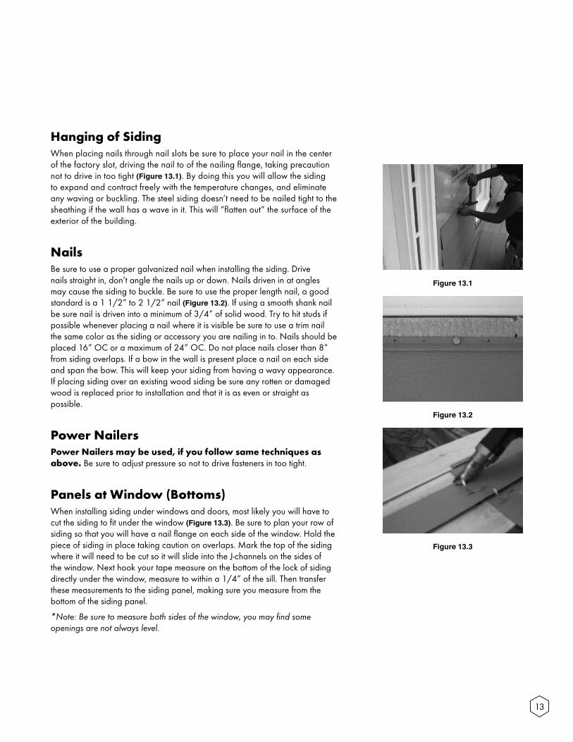
Hanging of SidingWhen placing nails through nail slots be sure to place your nail in the center of the factory slot, driving the nail to of the nailing flange, taking precaution not to drive in too tight (Figure 13.1). By doing this you will allow the siding to expand and contract freely with the temperature changes, and eliminate any waving or buckling. The steel siding doesn’t need to be nailed tight to the sheathing if the wall has a wave in it. This will “flatten out” the surface of the exterior of the building.
NailsBe sure to use a proper galvanized nail when installing the siding. Drive nails straight in, don’t angle the nails up or down. Nails driven in at angles may cause the siding to buckle. Be sure to use the proper length nail, a good standard is a 1 1/2” to 2 1/2” nail (Figure 13.2). If using a smooth shank nail be sure nail is driven into a minimum of 3/4” of solid wood. Try to hit studs if possible whenever placing a nail where it is visible be sure to use a trim nail the same color as the siding or accessory you are nailing in to. Nails should be placed 16” OC or a maximum of 24” OC. Do not place nails closer than 8” from siding overlaps. If a bow in the wall is present place a nail on each side and span the bow. This will keep your siding from having a wavy appearance. If placing siding over an existing wood siding be sure any rotten or damaged wood is replaced prior to installation and that it is as even or straight as possible.
Power NailersPower Nailers may be used, if you follow same techniques as above. Be sure to adjust pressure so not to drive fasteners in too tight.
Panels at Window (Bottoms)When installing siding under windows and doors, most likely you will have to cut the siding to fit under the window (Figure 13.3). Be sure to plan your row of siding so that you will have a nail flange on each side of the window. Hold the piece of siding in place taking caution on overlaps. Mark the top of the siding where it will need to be cut so it will slide into the J-channels on the sides of the window. Next hook your tape measure on the bottom of the lock of siding directly under the window, measure to within a 1/4” of the sill. Then transfer these measurements to the siding panel, making sure you measure from the bottom of the siding panel.
*Note: Be sure to measure both sides of the window, you may find some openings are not always level.
Figure 13.1
Figure 13.2
Figure 13.3

14
Panels at Windows and Doors (Tops)Cutting out the tops of windows and doors is nearly the same as the bottoms. The difference in this process is the clearance needed to install the siding. When measuring your clearance, measure tight to the inside of the J-channel. When cutting horizontally, cut an extra 1/4” to allow for the bottom of this panel to slide over the lock of the lower panel and engage it (Figure 14.1 and Fiture 14.2).
FurringCheck to see if you need any furring to keep the slope angle of your siding correct. If needed nail furring behind the finish trim that covers your horizontal cut.
FinishingCut a piece of finish trim to exact measurement of your cut out. Install finish trim on cut edge and drop your panel into place. Then slide the utility trim down to cover any gap that may be noticeable where siding meets J-channel.
Gable End Measuring and CuttingAngle cuts will have to be made on siding in gable sidewalls. A pattern can easily be made for these angles. Start with two small pieces of siding, lock one piece onto the panel below the start of the gable. The other piece hold into the eave line. At the bottom of the second piece draw a line on the first piece, following the angle. Cut on this line with a power saw or tin snips. You now have a pattern to transfer your cut lines on each row of siding in gable. Be sure to check your pattern often, all gable slopes are not always straight. Any roof slope can be handled in this manner.
Installing Install the angled end of the siding into the J-channel first then lock the butt end of the siding into the lower row of siding (Figure 14.4). Make sure you maintain the proper allowance for expansion and contraction. The final row of the peak may be nailed with a trim nail that matches siding color, through the face of the siding. (Figure 14.5) Touch-up paint can be used to cover any exposed nail heads.
Figure 14.1
Figure 14.2
Figure 14.3
Figure 14.4
Figure 14.5

15
Final Row of Siding Under EavesThe last row of siding will most likely have to be cut down to fit under the eave (Figure 15.1). To do this measure from the lower rows lock to the bottom of the eave. Transfer this measurement to the panel to be cut. Use an electric shear to make this cut 1/4” below the line. Check to see if furring is needed to keep slope angle correct. If needed install furring. Install finish trim flush with the eave. Finish trim should be installed on the entire length of the wall. The siding can then be inserted into the finish trim and locked into the lower row of siding. This row may be held in place by applying a bead of caulk in the lock of this panel prior to installation. Trim nails may be needed in the weep holes to keep siding in place, be sure to use touch-up paint to cover exposed nail heads.
Board and Batten ApplicationBoard and Batten can be used as an accent or for an entire installation. Most of the techniques used for Board and Batten siding are the same as for horizontal siding, the main difference is that the starter strip is installed vertically and panels lock together vertically (Figure 15.2). When running extra-long lengths of Board and Batten, Z Strip should be used to start and stop the panels (Figure 15.3).
Accessories and StarterSnap a chalk line that is parallel to the eaves or tops of windows at the bottom of the building. Use this line to install 1” rat guard at the bottom of the building. Trim windows and doors completely with J-channel or finish trim. To install starter strip correctly drop a plumb line off center of the gable peak. Measure sideways off this line to set your first panel.
First RowMeasure the length of the first row and cut to length. Cut the batten off of this piece and install cut edge of panel under the bottom edge of starter strip (Figure 15.4). Cut the other row to length and lock this panel into the starter strip nail both rows completely through nailing flanges following proper nailing guidelines.
Subsequent RowsInstall rest of panels working both in right and left directions from the two center panels (Figure 15.5). This technique will allow for even spacing of battens. You can also nail a starter strip at the corner vertically and install panels in one direction, this should be done when battens don’t have to be spaced evenly.
Door and Window CutsCuts are made in the same fashion as for horizontal siding. Be sure to install finish trim on vertical cuts to hide cut edges of siding that may be visible. Furring may be needed to build out panel if vertical cuts are made in Battens. Be sure to nail furring on first then nail on finish trim, this technique should also be used at O.C.P.
Z Strip
Vertical Siding
Figure 15.1
Figure 15.2
Figure 15.3
Figure 15.4
Figure 15.5

16
Clean UpUse a mild soap and water for clean-up with a soft cloth or sponge. Do not rub excessively, this could cause damage to the surface. Do not use harsh abrasives. Mineral spirits may be used sparingly to remove grease or asphalt stains
Job SiteRe-install all fixtures and wires that were removed prior to installation. Scrap pieces, siding boxes, nails debris, etc. should be removed daily.
Replacing Damaged PanelsCut damaged panel just above the center with an electric shear. Remove the bottom section of damaged panel. Do not remove remaining siding panel.
Remove the top lock of the replacement panel as high under the lock as possible. Remove any burrs or imperfections that may have occurred while cutting. Slip the new piece of siding under the old lock. If this lock is to tight open gap with a flat screwdriver.
Apply adhesive caulk on the full length of the old panel 1/2” to 3/4” under old lock.
Install new piece of siding carefully over the top of the adhesive caulk and into the old lock. Press new panel into the caulk so that it makes contact the full width of siding. Do not nail this panel into place. Use this procedure for all replacement. Nail through weep hole with stainless steel trim nails to hold the panel in place.
Additional TipsIt may be necessary to leave J-channels or corner posts loose around openings to help for installation of short siding panels. You may also have to leave J-channels off to get short pieces in and slip a J-channel in after installation. Nailing for this procedure can be done into the back side of the J-channel at every other row into the casing which it is butted into. A nail set will help in this procedure to set your nails into the wood. If leaving J-channels loose bow out ends and slip siding into J-channels and lock together.

qualityedge.com
888.784.0878
SSIG
04
/201
5