installation guide - serad variateur/imdl-gi-1724-… · imdl drive installation guide r1724 - 4 -...
TRANSCRIPT
IMDL-GI-1724-EN
Digital DRIVE for Brushless motor
IMDL Series
Read manual before installing and respect
all indications with this icon:
INSTALLATION
GUIDE


IMDL Drive installation guide
R1724 - 3 - SERAD S.A
Table of Contents
1- Introduction ................................................................................... 4
1-1- Warning ...................................................................................... 4
1-2- IMDL series drive description ................................................... 5
2- Installation ..................................................................................... 7
2-1- General ....................................................................................... 7
2-2- Front view ................................................................................... 8
2-3- Top view ...................................................................................... 9
2-4- Bottom view .............................................................................. 10
2-5- Mounting ................................................................................... 11
2-6- Connector pin assignments ...................................................... 12
2-7- Cables ....................................................................................... 23
2-8- Connection diagrams / Protections .......................................... 24
2-9- Stand-alone drive ..................................................................... 25
2-10- Drive controlled by a motion controller ................................ 26
2-11- Connecting a motor brake ...................................................... 27
2-12- System checks before starting ................................................ 27
2-13- STATUS DISPLAY .................................................................. 28
2-14- Error messages: ..................................................................... 31

IMDL Drive installation guide
R1724 - 4 - SERAD S.A
1- Introduction
1-1- Warning
Read this manual before first installing, nonobservance may result in property
damages and in personal injuries.
Only suitable qualified personnel should undertake the mounting, installation,
operation and maintenance of the equipment must be complied with the general setup
and safety regulations for work on power installations (e.g. DIN, VDE, EN, IEC or
other national and international regulations).
It is important that all safety instructions are strictly followed. Personal injury can
result from a poor understanding of the safety requirements.
The following safety regulations should be followed:
VDE 0100Specification for the installation of power systems
up to 1000 V
VDE 0113 Electrical equipment of machines
VDE 0160Equipment for power systems containing electronic
components.
- Never open the equipment.
- Dangerous high voltages exist within the equipment and on the connectors.
Because of this, before removing any of the connectors, it is necessary to remove
the power and wait at least 5 minutes to allow the capacitors to discharge.
- Never connect or disconnect the drive with power applied.
- Some of the drive’s surfaces can be very hot.
Some of the drive's components are susceptible to damage from electrostatic
discharges. Always handle the equipment using appropriate anti-static precautions.
We have gone to great lengths to ensure this documentation is correct and complete. However, since it
is not possible to produce an absolutely error-free text. No responsibility will be assumed by SERAD
for all damages caused by using this documentation and software.
We reserve the right to make changes to all or part of the specification without prior notice.

IMDL Drive installation guide
R1724 - 5 - SERAD S.A
1-2- IMDL series drive description
Supply : IMDL230 : 230V AC ±10% single phase
IMDL400 : 400V AC ±10% three phase
Auxiliary supply : 24 V DC ±10%, 0.4A typical (0,7A max if all options)
Supply filter : Integral
Switching frequency : 6.67 kHz sine-wave PWM
DC bus voltage : 310 V for IMDL 230 series, 560V for IMDL 400 series
Braking resistance :
Integral IMDL 230 : 110 ohms 30W
IMDL 400 : 150 ohms 30W
Facility to add an external resistor :
Type Min. value Max.cont. power Max imp. power
IMDL230 /2 60 Ω 1000W 2300W
IMDL230 /5 30 Ω 1800W 4600W
IMDL400 /1 ou /5 80 Ω 2800W 7000W
Protection :
Short circuit between phases, phase to earth, over current, I2t
Over voltage, under voltage
Motor feedback fault
Motor feedback : Resolver
SinCos encoder Hiperface (option)
Master encoder :
Incremental encoger
Absolute encoder SSI
SinCos encoder Hiperface (option)
Virtual
Encoder emulation : Incremental : A, /A, B, /B, Z, /Z 1 to 100 000 points per rev
Diagnostic : STATUS display
Communication :
RS 232 MODBUS RTU
RS 422(option), RS 485 MODBUS RTU(option)
EtherCAT(option)
CANopen (option)
Digital inputs :
4 inputs (with 2 fast inputs I3 and I4)
12 additional inputs with expansion module (with 2 fast inputs I15 and I16)
Type: PNP, 24V DC, 8mA per input and 15 per fast input
Logic 0: Between 0 and 5 V
Logic 1: Between 8 and 30 V
Digital outputs :
2 outputs as standard
S1 : Relay, 48V dc / 48V ac, 3A max
S2 : NPN (open collector) 24V dc, 100mA
8 additional outputs with expansion module
Type : PNP 24V dc, 500mA max per output
Protected against short circuit and over temperature.
Analogue inputs :
2 inputs :
Input voltage : ±10 V
Maximum voltage : ±12 V
Input impedance : 20 Kohms
Resolution : 16 bits for input 1 and 12 bits for input 2

IMDL Drive installation guide
R1724 - 6 - SERAD S.A
Analogue output :
1 output :
Output voltage : ±10 V
Maximum current : 5 mA
Resolution : 8 bits, bandwidth 20Hz
Architecture :
Processor :150 MHz DSP and 100 000 gates FPGA
FLASH memory for programs and parameters
RAM memory for data
FRAM memory for variables
Real-time, multi-tasking kernel
Control loops :
Current loop : 75 µs
Speed loop : 150 µs
Position loop : 150µs
Operating modes :
Torque mode
Speed mode
Position mode
Stepper Mode (pulse input, direction)
Motion functions (absolute, relative and infinite movements, S profile)
Advanced motion functions (gearbox, CAM profiles, CAMBOX functions, triggered movement)
Operating temperature : 0 to 40°C
Storage temperature : -10 to 70°C
Degree of protection : IP 20
Weight 3,6 Kg
Drive Rated current Peak current ( 2s ) Rated power Dimensions w x h x d
IMDL230 / 2 2,5 Aeff 5 Aeff 0,7 kVA 64 x 293 x 201
IMDL230 / 5 5 Aeff 10 Aeff 1,5 kVA 64 x 293 x 201
IMDL400 / 1 1,25 Aeff 2,5 Aeff 0,7 kVA 64 x 293 x 201
IMDL400 / 4 4 Aeff 8 Aeff 2,2 kVA 64 x 293 x 201

IMDL Drive installation guide
R1724 - 7 - SERAD S.A
2- Installation
2-1- General
It is very important to adhere to the following:
A badly earthed connection can damage electronic drive components.
The drive must be installed vertically in free air to ensure cooling by natural
convection.
It must be protected from excess humidity, liquids, and dirt.
The motor, resolver and encoder cables must be screened, the screen being earthed
at both ends of the cable.
The analogue I/O must use screened cable, the screen being earthed at one end
only.
The cable for the RS 232 serial link between the drive and the PC must be screened,
the screen being earthed at both ends of the cable. It should be disconnected from the
drive when no longer in use. All of these cables, as well as the I/O cables, should be
run separately from the power cables.
Diodes must be fitted across the loads on all static digital outputs (Q2 to Q10).
These diodes must be positioned as close to the load as possible. The supply and
signal cables must be free from over-voltage transients.
Safety standards specify a manual reset after a stop caused either by a supply
interruption, or by an emergency stop or by a drive fault.
For all serious faults, it is obligatory to remove the high voltage supply to the drive.
The Drive Ready output should be connected in series in the emergency stop loop.
In the case of axis over-travel, the over-travel limit switches must be connected to
the limit inputs or in series with the emergency stop loop. It is also recommended to
use the software limits.
If the drive is configured in speed loop, the drive enable input should be controlled
by the supervisory controller (CNC, PLC etc).
If the drive is configured in position loop, the parameter "Maximum following
error" should be set appropriately.
If the drive contains an application program developed using iDPL, connect a
signal ‘Cabinet supplies OK’ to one of the digital inputs and monitor it in a non-
blocking safety task. On detection of an excess following error the drive will be put in
open loop mode and the drive ready relay will be opened. If another action is required
you should use the SECURITY instruction.
IMDL Drive installation guide
R1724 - 8 - SERAD S.A
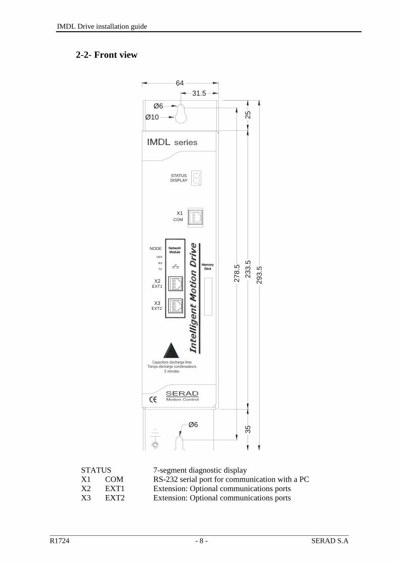
2-2- Front view
STATUS 7-segment diagnostic display
X1 COM RS-232 serial port for communication with a PC
X2 EXT1 Extension: Optional communications ports
X3 EXT2 Extension: Optional communications ports
DISPLAYSTATUS
COM
X1
EXT2
EXT1
X3
X2
TX
RX
NODE
OFF
Memory
Stick
Memory
Stick
Network
Module
Network
Module
27
8.5
293
.5
25
35Ø6
233.5
Ø6
Ø10
64
31.5

IMDL Drive installation guide
R1724 - 9 - SERAD S.A
2-3- Top view
X4 ENCODER OUTPUT Multifunction encoder output
X5 ENCODER INPUT Multifunction encoder input
X6 AUX. SUPPLY 24VCC Auxiliary 24V DC supply
X7 DIGITAL I/O Digital I/O
X8 BALLAST External braking resistor
X9 EXTENDED I/O Option: I/O expansion board
X SAFE Option : Secure input
The voltage on connector X8 can reach 400V for an IMDL 230 and 800V for an
IMDL 400!
64.0
201.5
X9
-E
XT
EN
DE
DI/O
X8-B
ALL
AS
TX
7-D
IGIT
AL
I/O
X6
-A
UX
.
SU
PP
LY
24V
CC
X5
-E
NC
OD
ER
INP
UT
X4
-E
NC
OD
ER
OU
TP
UT
1
2
3
12345678
1
2 +
4 X
- S
AFE

IMDL Drive installation guide
R1724 - 10 - SERAD S.A
2-4- Bottom view
X10 POWER Single / Three-phase supply Motor armatures
X11 FEEDBACK Motor position feedback (resolver / encoder)
X12 ANALOG Analogues I/O
X 13 SINCOS Motor position feedbacks (if SINCOS encoder is used)
Care must be taken when making connection to connector X10. An incorrect
connection can seriously damage the drive. Dangerous voltages are present on X10.
Wait at least 5 minutes to allow the capacitors to discharge before remove connector.
X12
AN
AL
OG
I /O
X11
RE
SO
LV
ER
X1
3-S
INC
OS
X10
-P
OW
ER
SU
PP
LY
/M
OT
OR

IMDL Drive installation guide
R1724 - 11 - SERAD S.A
2-5- Mounting
Several drives can be mounted side-by-side provided that enough space (at least 20
mm) is left to ensure good natural convection. Let a space greater than 90 cm over and
under drives to allow for the various connectors and cables to be fitted
35
23
3.5
25
X8- BALLAST
RB
RI
21 3
I27
X7 - DIGITALI/O
X6 - AUX.SUPPLY
I4 I 3
24V
2121 53 4 6
ENCODER INPUT
X5
ENCODER OUTPUT
X4I18
Intelligent Motion Drive
SERAD Motion Control
271, route des crêtes
EXTENDED I/O
X9
X10 - POWER SUPPLY / MOTOR
Capacitors discharge time : 5 minutes
High voltage on X8 - X10 connectors
All the PE pins must be connected
Read manual before installing
Temps de décharge des condensateurs : 5 minutes
Haute tension sur les connecteurs X8 - X10
Toutes les bornes PE doivent être raccordées
Lire le manuel avant l'utilisation
L3
L2
PE
PE
L1
21 53 4
WU V
876
X11
RESOLVER
X12
ANALOG I/O
SINCOS
X13
www.serad.fr44440 TEILLE
RACCORDEMENT
BLINDAGE MOTEUR
80
23
3.5
90
4
IMDL Drive installation guide
R1724 - 12 - SERAD S.A
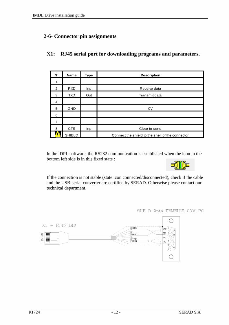
2-6- Connector pin assignments
X1: RJ45 serial port for downloading programs and parameters.
N° Name Type Description
1
2 RXD Inp Receive data
3 TXD Out Transmit data
4
5 GND 0V
6
7
8 CTS Inp Clear to send
SHIELD Connect the shield to the shell of the connector
In the iDPL software, the RS232 communication is established when the icon in the
bottom left side is in this fixed state :
If the connection is not stable (state icon connected/disconnected), check if the cable
and the USB-serial converter are certified by SERAD. Otherwise please contact our
technical department.
3-TXD2-RXD
5-GND
78-CTS
6
4
1

IMDL Drive installation guide
R1724 - 13 - SERAD S.A
X2 & X3: Extension: Optional communications port
X2 and X3 are identical and have the same connection. They make easier drive
network connection.
For the TCP module, refer to the documentation TCP option installation guide
available on www.serad.fr
Node Address : For RS422, RS485 and CANopen, the NodeID corresponds to the
five firstly dipswitchs + 1
Ex:
For the RS422, RS485 and CANopen module, the terminal resistor is activated by the dip
switch n°6 (120Ω).
In CANopen, do not use the Node ID n° 1 if you have a multi drive project.
RS232 communication allows communication with only 1 device (ex: 1 PLC
and 1 IMD drive).
N° Module RS 232 Module RS 422 Module RS 485 Module CANopen Module EtherCAT Module TCP
1 TD + TD +
2 RXD RX+ TD - TD -
3 TXD RX- RD + RD +
4
5 GND GND GND GND
6 RD - RD -
7 TX- TRX- CAN_L
8 TX+ TRX+ CAN_H
Connect the shield to the shell of the connector

IMDL Drive installation guide
R1724 - 14 - SERAD S.A
Node Address : For RS422, RS485 and CANopen, the NodeID corresponds to the
six firstly dipswitchs + 1
Ex:

IMDL Drive installation guide
R1724 - 15 - SERAD S.A
X4: Multifunction encoder output:
Encoder emulation output
The choice of the number of points is made from the iDPL software.
Connector : SUBD 9 way female
NC (Not connected): It is forbidden to connect this pins.
N° Name Type Encoder emulation
1 A Out Channel A
2 /A Out Channel A inverted
3 B Out Channel B
4 /B Out Channel B inverted
5 Z Out Channel Z
6 /Z Out Channel Z inverted
7
8 GND 0V
9
SHIELD Connect the shield to the shell of the connector

IMDL Drive installation guide
R1724 - 16 - SERAD S.A
X5: Multifunction encoder input:
Incremental encoder input
SSI encoder input
Stepper input
The choice of the input is made in iDPL software in the Multifunction encoder input
windows
TTL 5V encoder (0-5V, differential)
Connector : SUBD 9 way male
* If the feedback is SINCOS then don’t use 5V powersupply (pin 7 of connector X5)
but an external powersupply.
NC (Not connected): It is forbidden to connect this pins.
X6: 24V dc supply
Connector: Removable 2 ways, 5.08mm pitch
N° Name Type Description
1 XGND 0V
2 24Vdc Inp Control card supply, backup motor position
N° Name Type Incremental encoder Codeur SSI Stepper IMDbus
1 A Inp Channel A Data Direction Data
2 /A Inp Channel A inverted /Data /Direction /Data
3 B Inp Channel B NC Pulse Clock
4 /B Inp Channel B inverted NC /Pulse /Clock
5 Z I/O Zero marker Clock NC NC
6 /Z I/O Zero marker inverted /Clock NC NC
7 +5Vdc OutSupply for external
encoder, 100 mA max.*NC NC NC
8 GND 0V 0V 0V 0V
9 Inp NCSSI selection : Connect
pins 8 and 9NC NC
SHIELD Connect the shield to the shell of the connector

IMDL Drive installation guide
R1724 - 17 - SERAD S.A
X7: Digital I/O
Connector: Removable 8 ways, 3.81mm pitch
N° Name Type Description
1 Q2 Out Output 2, programmable : type NPN, 24 Vdc, 100mA
2 Q1 Out Output 1, programmable : standard function DRIVE READY
3 Q1 Relay contact, N/O between terminals 2 and 3
4 DGND 0V digital I/O
5 I4 Inp Input 4, programmable
6 I3 Inp Input 3, programmable
7 I2 Inp Input 2, programmable
8 I1 Inp Input 1, programmable:standard function ENABLE
The output Q2 is NPN open collector: the load must be connected between
Q2 and +24V DC.
X8: High voltage supply
Connector: Removable 4 ways, 7.62mm pitch
No. Name Type Description
1 RI Internal braking resistor *
2 RB Braking resistor *
3 DC Bus + Out DC bus (310 V for IMDL 230, 560 V for IMDL 400)
4 DC Bus - Out DC bus (310 V for IMDL 230, 560 V for IMDL 400)
*Selection of the braking resistor:
- Internal resistor: Fit a link between terminals 1 and 2
- External resistor: Remove the link between terminals 1 and 2
Connect the external resistor between terminals 2 and 3
The voltage on connector X8 can reach 400V for an IMDL 230 and 800V for an IMDL
400!

IMDL Drive installation guide
R1724 - 18 - SERAD S.A
X9: Option: Expansion module, 12 inputs / 8 outputs
Connector: SUBD 25 way female
N° Name Type Description
1 I5 Inp Input 5, programmable
2 I6 Inp Input 6, programmable
3 I7 Inp Input 7, programmable
4 I8 Inp Input 8, programmable
5 I9 Inp Input 9, programmable
6 I10 Inp Input 10, programmable
7 IOGND* 0V digital I/O
8 Q3 Out Output 3, programmable
9 Q4 Out Output 4, programmable
10 Q5 Out Output 5, programmable
11 Q6 Out Output 6, programmable
12 IO 24Vdc** Inp External supply, 24 V dc
13 IO 24Vdc** Inp External supply, 24 V dc
14 I11 Inp Input 11, programmable
15 I12 Inp Input 12, programmable
16 I13 Inp Input 13, programmable
17 I14 Inp Input 14, programmable
18 I15 Inp Input 15, programmable
19 I16 Inp Input 16, programmable
20 Q7 Out Output 7, programmable
21 Q8 Out Output 8, programmable
22 Q9 Out Output 9, programmable
23 Q10 Out Output 10, programmable
24 IOGND* 0V digital I/O
25 IOGND* 0V digital I/O
SHIELD Connect the shield to the shell of the connector
* Pins 7, 24, 25: internal connection
** Pins 12, 13: internal connection

IMDL Drive installation guide
R1724 - 19 - SERAD S.A
X10: Motor armature
Connector: Removable 8 ways, 7.62mm pitch
No. Name Type Description
1 PE Supply earth
2 L1* In Supply L1 (230V for IMDL 230, 400V for IMDL 400)
3 L2* In Supply L2 (230V for IMDL 230, 400V for IMDL 400)
4 L3 In Supply L3 (230V for IMDL 230, 400V for IMDL 400)
5 PE Motor earth
6 U Out Motor phase U
7 V Out Motor phase V
8 W Out Motor phase W
For a 230V ac single-phase supply, connect Live to L1 and Neutral to L2
SERAD MOTOR
C
A
1
4
B
D
3
Shield reverse
around the ring
1
4
3
2
C
Phase U
D
Phase V
Phase W
Earth
Break +
Break -
DESCRIPTION
Attention. Care must be taken when making connection to connector X10. An
incorrect connection can seriously damage the drive. Dangerous voltages are present
on X10.
The armoured motor cable must arrive directly on the terminals of the drive.
Connect the shield (on drive side) to the srew provided (see 2-2 Front view).
The maximum length for the power and feedback cables is 20m. For more than
20m, please contact our technical support.
IMDL Drive installation guide
R1724 - 20 - SERAD S.A
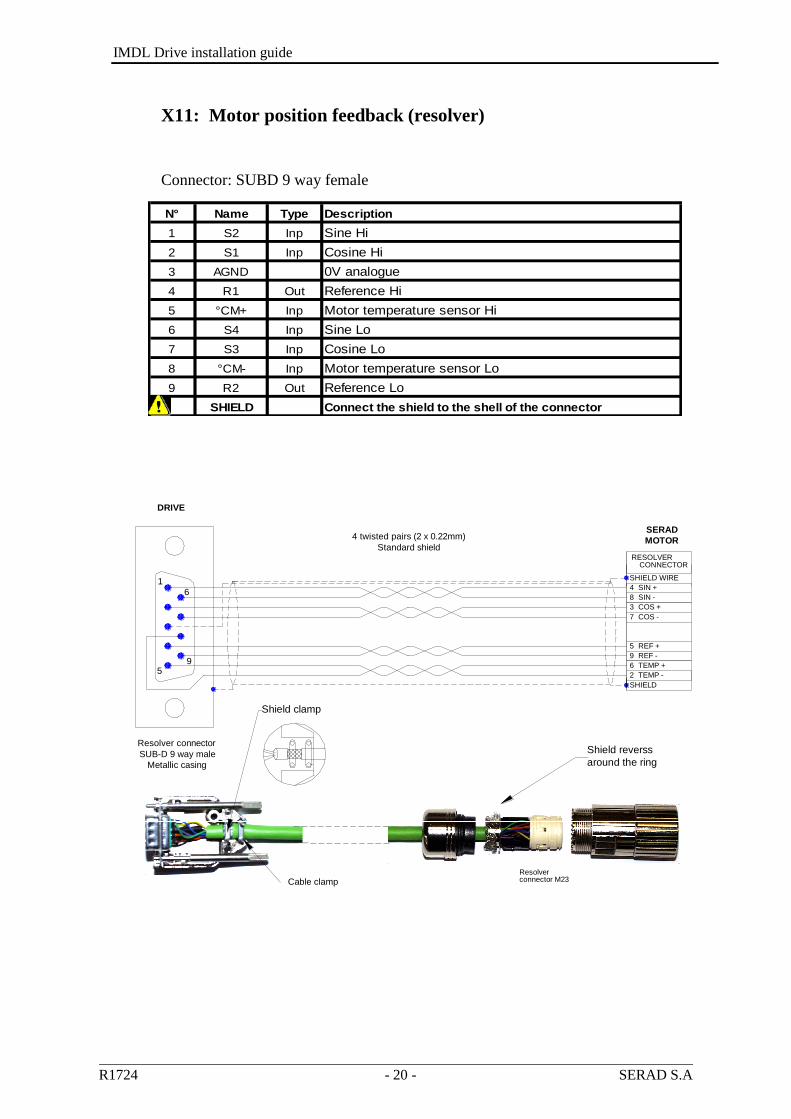
X11: Motor position feedback (resolver)
Connector: SUBD 9 way female
N° Name Type Description
1 S2 Inp Sine Hi
2 S1 Inp Cosine Hi
3 AGND 0V analogue
4 R1 Out Reference Hi
5 °CM+ Inp Motor temperature sensor Hi
6 S4 Inp Sine Lo
7 S3 Inp Cosine Lo
8 °CM- Inp Motor temperature sensor Lo
9 R2 Out Reference Lo
SHIELD Connect the shield to the shell of the connector
1
5
6
9
Resolver connector
SUB-D 9 way male
Metallic casing
Cable clamp
RESOLVER
SHIELD WIRE
2 TEMP -
SHIELD
5 REF +
6 TEMP +
9 REF -
4 SIN +
8 SIN -
7 COS -
3 COS +
CONNECTOR
Shield reverss
around the ring
connector M23Resolver
4 twisted pairs (2 x 0.22mm)
Standard shield
DRIVE
SERAD
MOTOR
Shield clamp
IMDL Drive installation guide
R1724 - 21 - SERAD S.A
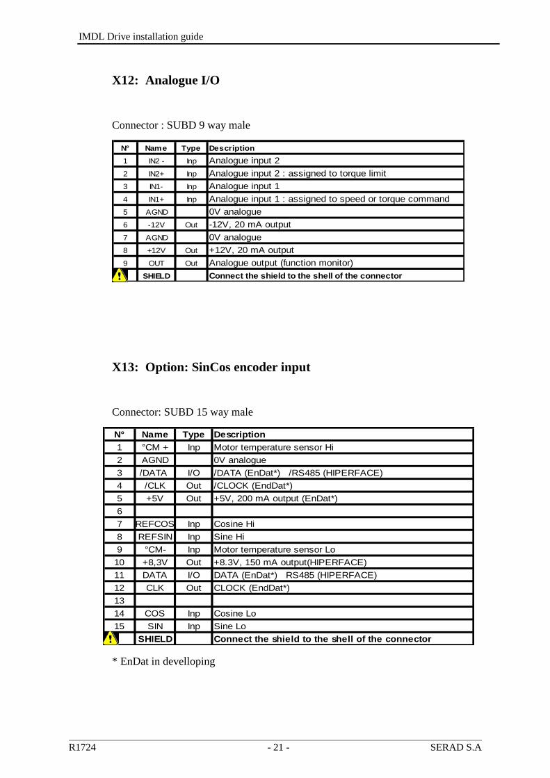
X12: Analogue I/O
Connector : SUBD 9 way male
N° Name Type Description
1 IN2 - Inp Analogue input 2
2 IN2+ Inp Analogue input 2 : assigned to torque limit
3 IN1- Inp Analogue input 1
4 IN1+ Inp Analogue input 1 : assigned to speed or torque command
5 AGND 0V analogue
6 -12V Out -12V, 20 mA output
7 AGND 0V analogue
8 +12V Out +12V, 20 mA output
9 OUT Out Analogue output (function monitor)
SHIELD Connect the shield to the shell of the connector
X13: Option: SinCos encoder input
Connector: SUBD 15 way male
N° Name Type Description
1 °CM + Inp Motor temperature sensor Hi
2 AGND 0V analogue
3 /DATA I/O /DATA (EnDat*) /RS485 (HIPERFACE)
4 /CLK Out /CLOCK (EndDat*)
5 +5V Out +5V, 200 mA output (EnDat*)
6
7 REFCOS Inp Cosine Hi
8 REFSIN Inp Sine Hi
9 °CM- Inp Motor temperature sensor Lo
10 +8,3V Out +8.3V, 150 mA output(HIPERFACE)
11 DATA I/O DATA (EnDat*) RS485 (HIPERFACE)
12 CLK Out CLOCK (EndDat*)
13
14 COS Inp Cosine Lo
15 SIN Inp Sine Lo
SHIELD Connect the shield to the shell of the connector
* EnDat in develloping
IMDL Drive installation guide
R1724 - 22 - SERAD S.A
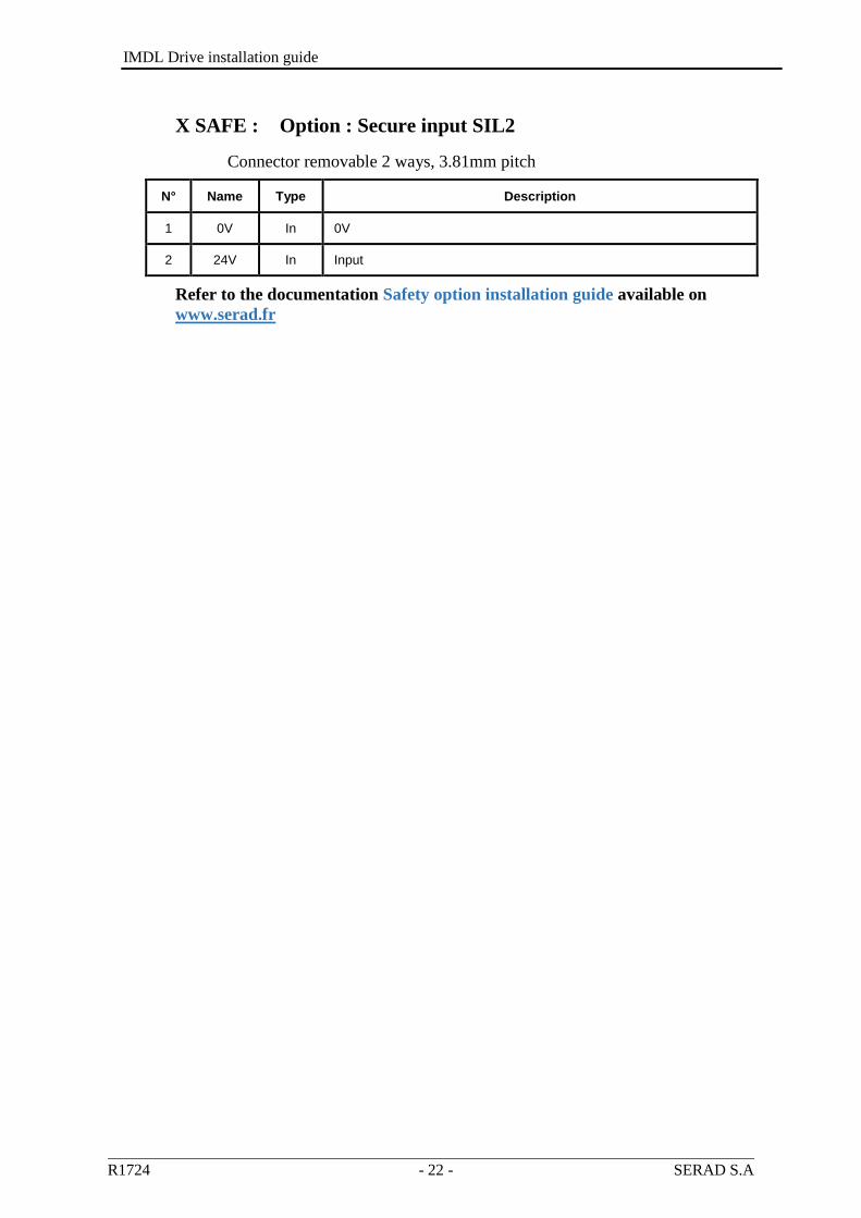
X SAFE : Option : Secure input SIL2
Connector removable 2 ways, 3.81mm pitch
N° Name Type Description
1 0V In 0V
2 24V In Input
Refer to the documentation Safety option installation guide available on
www.serad.fr

IMDL Drive installation guide
R1724 - 23 - SERAD S.A
2-7- Cables
We can made you all cables with connectors (standard, robotics ...), contacts us.
RS 232 serial communication cable, X1:
Screened cable, 4 core
Connect the shield on each extremity, to the shell of the connector (RJ45 and
SUBD).
Encoder cable, X4/X5:
Screened cable with 4 twisted pairs, 0.25 mm²
Connect the shield on each extremity, to the shell of the connector.
Analogue cable, X12:
Screened cable, 2 core, 0.25 mm² per analogue input.
Connect the shield: on drive side to the screw provided (see 2-2 Front view) and
on the other side to the shell equipment (ex. Motion controller …)
Motor feedback cable (resolver), X11:
Screened cable with 4 twisted pairs, 0.25 mm²
Ground the shield of the feedback SUBD as shown below:
Motor power cable, X10:
Screened cable, 4 core, (+2 for a brake), 1.5 mm² until 8A drive else use 2,5 mm²
Connect the shield (on drive side) to the screw provided (see Front view of the
drive).

IMDL Drive installation guide
R1724 - 24 - SERAD S.A
2-8- Connection diagrams / Protections
All connections must be realised by qualified personnel. The cables must be
tested before being connected as any wiring fault can give rise to serious
problems
Remove all voltages before inserting the connectors.
Ensure that the earth connection to the drive is correctly made (pin 4 of the
connector X8).
Connect the motor earth to the drive (pin 5 of the connector X10) before applying
any voltages.
For the shielded cables, to connect the braid to the frame at each extremity via
the caps of the connectors (for the SUBD) or the screws provided for this purpose
(X7) in order to ensure an optimal equipotentiality.
Preventive reference rejection measures should be taken for control panel, such
as connections contactors (obligatory on brake) and relay using RC elements or
diodes( ex 1N4007).
Drive Input voltage Max. input current Safety device : cutout C curve
Wire
IMDL230 / 2 230V monophasé 7A 10A maxi 1,5²
IMDL230 / 5 230V monophasé 14A 10A maxi 1,5²
IMDL400 / 1 400V three phase 2,2A 10A maxi 1,5²
IMDL400 / 4 400V three phase 6,6A 10A maxi 1,5²
Caution: the ringing current can reach 25A during 10ms.
IMDL Drive installation guide
R1724 - 25 - SERAD S.A
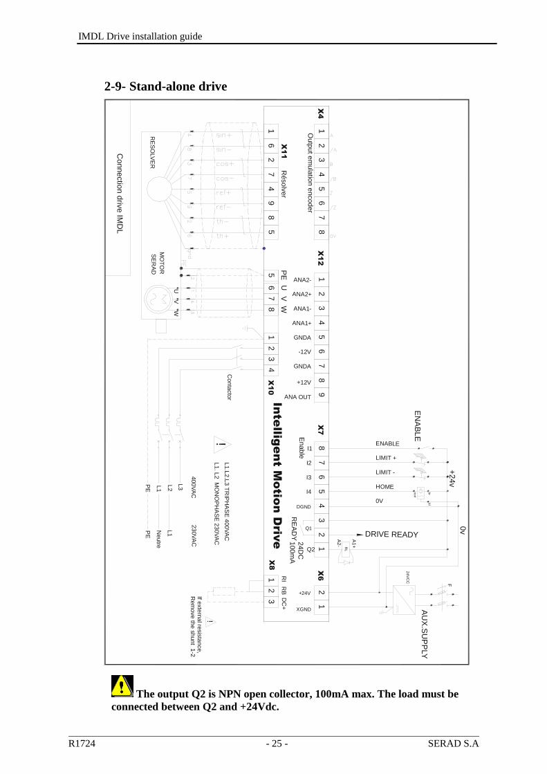
2-9- Stand-alone drive
The output Q2 is NPN open collector, 100mA max. The load must be
connected between Q2 and +24Vdc.
Inte
llig
en
t M
otio
n D
rive
EN
AB
LE
Rem
ove th
e s
hunt 1
-2If e
xte
rnal re
sis
tance,
Co
nn
ectio
n d
rive
IMD
L
RE
SO
LV
ER
MO
TO
R
UV
W
8 7.
7
X1
1
16
24
9
4
Outp
ut e
mu
latio
n e
nco
der
21
35
64
ANA2+
ANA2-
ANA1-
55
67
8
PE
UV
W
X1
28
21
3
ANA OUT
GNDA
-12V
+12V
GNDA
ANA1+
41
23
X1
0
!
75
69
8
Conta
cto
r
L1. L
2 M
ON
OP
HA
SE
230V
AC
L1.L
2.L
3 T
RIP
HA
SE
400V
AC
!
230V
AC
L3L1
L2
400V
AC
PE
1
0V
ENABLE
LIMIT +
LIMIT -
HOME
DRIVE READY
3
Ena
ble
DGND
7
I2
X7
8
I1
5
I4
6
I3
4
24
DC
+24V
XGND
RE
AD
Y
X8
10
0m
A
12
3
RB
RI
DC
+
A2
-
2Q1
1
Q2
RL
A1
+
2X
6
+24v
no
ir
br
bl
24
VC
C
F
0vN
eutre
L1
X4
Ré
so
lve
r
SE
RA
DP
E
AU
X.S
UP
PLY

IMDL Drive installation guide
R1724 - 26 - SERAD S.A
2-10- Drive controlled by a motion controller
The output Q2 is NPN open collector, 100mA max. The load must be
connected between Q2 and +24Vdc.
With
MC
S 3
2ex
Connectio
n d
rive IM
DL
AX
IS
SR
V 8
5
.
HO
ME
noir
br
bl
DRIVE READYA2
- RL
A1
+
+24v
EN
AB
LE 0
v
24V
CC
F
Q2
Q1
XGND
+24V
I3
I4
I1
I2
DGND
ANA1+
GNDA
+12V
-12V
GNDA
ANA OUT
ANA1-
ANA2-
ANA2+
L1.L
2.L
3 T
RIP
HA
SE
40
0V
AC
L1. L
2 M
ON
OP
HA
SE
230
VA
C
Intellige
nt M
otion D
rive
61
WV
U
RE
SO
LV
ER
MO
TO
R
5
Résolv
er
42
7
X11
98
PE5
87
6
VU
W
L3PE
L2L1
Co
nta
cto
r
43
21
X10
!
400
VA
C
Enable
L1
Ne
utre
DC
+
3
230
VA
C 100m
A
24D
CR
EA
DY
21
X8
RI
RB
42
X4
.1
48
53
46
71
X12
23
76
59
87
X7
85
61
12
3X
62
SE
RA
D
PE
If exte
rna
l resis
tance
, R
em
ove
the
sh
un
t 1-2
!
Outp
ut e
mula
tion e
ncoder
AU
X. S
UP
PLY

IMDL Drive installation guide
R1724 - 27 - SERAD S.A
2-11- Connecting a motor brake
The output Q2 is NPN open collector, 100mA max. The load must be
connected between Q2 and +24Vdc.
Using the iDPL parameter set-up window, select the function Brake for output 2.
It is obligatory to put the 2 protection diodes else drive components can be
damaged.
2-12- System checks before starting
With the Enable input off, switch on the auxiliary 24V dc supply.
Ensure that on the STATUS display, the point blinking.
Apply power.
If the Status display shows an error message check the list of error codes.
X7
READY
24DC100mA
Statique
Relay
8
7
6
5
4
3
2
1
i1
i2
i3
i4
DGND
Q1
Q2
F2
Brake
Motor
24Vcc
+
-
0v
+24Vcc
External
Power
24Vcc
+/- 10%F1
diodeprotect
DRIVE
IMD
protectdiode
+24Vcc
Input

IMDL Drive installation guide
R1724 - 28 - SERAD S.A
2-13- STATUS DISPLAY
When the drive is starting
1) BOOT initialisation
Before the initialisation of the boot, the STATUS DISPLAY display :
In case of initialisation fault, you may have the following faults :
: Checksum fault during the initialisation.
: The OS is not loaded correctly. Refer to the documentation loading of
operating system available on www.serad.fr
: Internal fault
2) OS initialisation
The segments switch on fastly in the following order :
3) End initialisation, the number of OS version is displayed
The example above gives you the OS version 3.38

IMDL Drive installation guide
R1724 - 29 - SERAD S.A
Drive running
Blinking of the point
If system is linking (IDPL link) :
If the drive is not linked :
Enable state
If the instructions display is used in a tasks, the display is a priority.
Motor position state
The segments around are moving serving the motor position.
If the instructions display is used in a tasks, the display is a priority.
ON : enable
OFF : disable
Rotation
moving -
Rotation
moving +

IMDL Drive installation guide
R1724 - 30 - SERAD S.A
X-SAFE state
In case of drive with safety option :
3 segments horizontales blinking indicate they don’t have 24v on the X-safe
connector.
When the 24v is back again on the X-safe connector, the status display go back
on normal running, if the instruction display have been used before, the status
display can be locked on this state :
When a new instruction display is used the satus display will change.

IMDL Drive installation guide
R1724 - 31 - SERAD S.A
2-14- Error messages:
DC Bus over-voltage : an over-voltage has been detected on the
internal dc bus. This fault can be due either to an over-voltage on
the supply or to the braking resistance being insufficient.
DC Bus under-voltage : an under-voltage has been detected on the
internal dc bus. This condition is only monitoring when the drive is
active (Enable = ON, tension DC Bus voltage lesser then a drive’s
parameter ) and when drive try to pass enable (DC Bus voltage
lesser than 250V).
I²t motor : I²t motor detected.
Over-current : a current greater than the maximum current has
been detected. The drive must be powered 24Vdc (Connector X6) for 15 min
before it can be unlocked (iDPL v3.38 or higher). Immediate unlocking possible
by computer in advanced mode.
Short-circuit : a short-circuit between phases or between a motor
phase and earth has been detected. The drive must be powered 24Vdc
(Connector X6) for 15 min before it can be unlocked (iDPL v3.38 or higher).
Immediate unlocking possible by computer in advanced mode.
Temperature IGBT : maximum temperature attained in the drive.
Temperature motor : maximum motor temperature attained.
Resolver fault : Resolver feedback or absolute encoder or
SinCOS signals defective.
Invalid parameters : checksum error on the drive parameters or
parameters not initialised.
Drive type error : the parameter file does not correspond to the
drive type or parameters not configured.
iDPL error : an error has been detected during the execution of the
iDPL tasks (division by zero, not correct instruction, CAM or
synchro. movement error …).
Following error : the maximum following error has been
exceeded.Contact technical support.
FLASH memory error: impossible writting. Contact technical
support.
IMDL Drive installation guide
R1724 - 32 - SERAD S.A
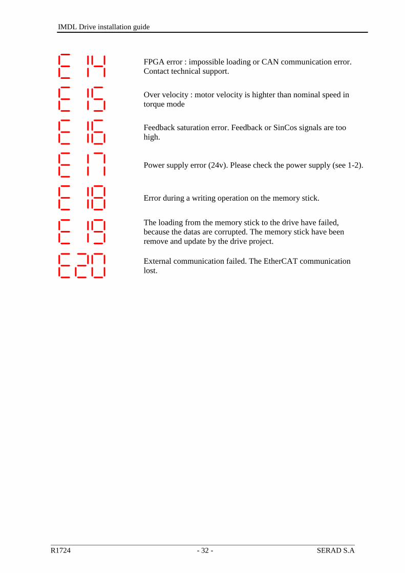
FPGA error : impossible loading or CAN communication error.
Contact technical support.
Over velocity : motor velocity is highter than nominal speed in
torque mode
Feedback saturation error. Feedback or SinCos signals are too
high.
Power supply error (24v). Please check the power supply (see 1-2).
Error during a writing operation on the memory stick.
The loading from the memory stick to the drive have failed,
because the datas are corrupted. The memory stick have been
remove and update by the drive project.
External communication failed. The EtherCAT communication
lost.
