installation instructions 17
TRANSCRIPT
Hydraulic Power Assist for SeaStarSteering Systems
Including:
Before you do it your way,
please try it our way
17.2
INSTALLATION INSTRUCTIONS
AND OWNER'S MANUAL
w w w . s e a s t a r s o l u t i o n s . c o m
SEVENTEENPOINT TWO
ISO 9001

Power Assist for SeaStar Systems i
Throughout this publication, Warnings and Cautions (accompanied by theInternational Hazard Symbol ) are used to alert the manufacturer orinstaller to special instructions concerning a particular service oroperation that may be hazardous if performed incorrectly or carelessly.
Observe Them Carefully!
These safety alerts alone, cannot eliminate the hazards that theysignal. Strict compliance to these special instructions when performingthe installation and maintenance plus common sense operation are majoraccident prevention measures.
Notice to Boat Manufactureror Installer
Hazards or unsafepractices whichCOULD result inminor injury orproduct or propertydamage.
CAUTIONHazards or unsafepractices whichCOULD result insevere personalinjury or death.
WARNINGImmediate hazardswhich WILL result insevere personalinjury or death.
DANGERInformation which isimportant to properinstallation ormaintenance, but isnot hazard-related.
NOTICE
Cleaning fluids containing ammonia, acids or any other corrosiveingredients MUST NOT be used for cleaning any part of thisHydraulic Steering System. Failure to comply will cause seriousdamage to the steering system, resulting in possible loss ofsteering, causing property damage, personal injury and/or death.
WARNING
Help protect your boating environment by ensuring that all used oilis disposed of properly.
NOTICE
NOTICE
Don't compromise performance... use genuineSeaStar parts only!• SeaStar Helms • SeaStar Cylinders• SeaStar Hoses • SeaStar Oil
Substituting non SeaStar parts in any part of the SeaStar hydraulicsteering system, may seriously compromise system performance.
Please ensure this manual is left on board theboat for future reference.
Marine Canada Acquisition Inc. DBA SeaStar Solutions is referred toas SeaStar Solutions throughout this publication.
ii SEASTAR Hydraulics ii
INTRODUCTION
IndexBefore Operating Your Boat ........................................................ 1Compatibility/Tools/Specifications.............................................. 2How The System Works ............................................................. 3Things You Need to Know .......................................................... 4Before Starting ......................................................................... 4System Installation Overview...................................................... 5
Specific InstallationOutboard Front Mount & HC5332............................................... 6Side Mount & Splashwell Mount Cylinders .................................. 9Inboard & Sterndrive ............................................................... 10Autopilot Connection................................................................ 11Electrical Installation ............................................................... 12Power Purge Filling and Purging................................................ 14Manual Filling and Purging ....................................................... 15Troubleshooting....................................................................... 21Accessories ............................................................................ 23Mounting Templates ................................................................ 25Warranty ................................................................................. 29
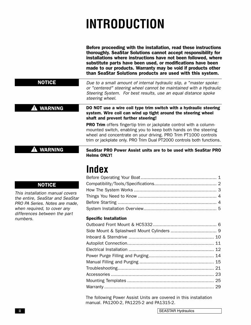
Before proceeding with the installation, read these instructionsthoroughly. SeaStar Solutions cannot accept responsibility forinstallations where instructions have not been followed, wheresubstitute parts have been used, or modifications have beenmade to our products. Warranty may be void if products otherthan SeaStar Solutions products are used with this system.
Due to a small amount of internal hydraulic slip, a "master spoke:or "centered" steering wheel cannot be maintained with a HydraulicSteering System. For best results, use an equal distance spokesteering wheel.
DO NOT use a wire coil type trim switch with a hydraulic steeringsystem. Wire coil can wind up tight around the steering wheelshaft and prevent further steering!
PRO Trim offers fingertip trim or jackplate control with a column-mounted switch, enabling you to keep both hands on the steeringwheel and concentrate on your driving. PRO Trim PT1000 controlstrim or jackplate only. PRO Trim Dual PT2000 controls both functions.
NOTICE
WARNING
This installation manual coversthe entire, SeaStar and SeaStarPRO PA Series. Notes are made,when required, to cover anydifferences between the partnumbers.
NOTICE
SeaStar PRO Power Assist units are to be used with SeaStar PROHelms ONLY!
WARNING
The following Power Assist Units are covered in this installationmanual. PA1200-2, PA1225-2 and PA1315-2.

Power Assist for SeaStar Systems 1
Ensure that the following check list is carried out
1 With the P/A unit "OFF" (ignition off) perform a system pressuretest by turning the helm all the way to hard over and then forcingthe helm another one quarter to one half turn past the stop point.
Inspect the following areas for leaks.- Inspect helm fittings- Inspect P/A fittings- Inspect cylinder fittings
Look for evidence of a leak. This test is to be done in BOTHdirections. Any leak that is noticed will need to be repairedbefore operating the boat.
2 Confirm that extruded nylon tubing has NOT beensubstituted for SeaStar/SeaStar PRO Hydraulic Steering hose.
3 Confirm that there is no interference between the steeringcylinder and the transom, splashwell or jackplate or anycombination of these parts by performing these simple steps:
• If installed on an outboard engine, with the engine fully titled,turn steering from hard over to hard over and confirm that NOinterference occurs. If you are using a hydraulic jack plate thisalso must be performed at the top and bottom position of thejack plate. (If interference is present, it MUST be eliminatedwith trim limiting switches and/or jack plate restrictors. ContactJack plate manufacturer for advice if required.)
• Confirm that the steering cylinder can be stroked fully in bothdirections as well as full tilt and trim without stretching and/orkinking the hydraulic hoses.
• Confirm that the hydraulic hose/tube are not subjected to chafing,rubbing or stretching. Stretched, kinked or chafed hose/tube willfail over a period of time leading to loss of steering control.
BEFORE OPERATINGYOUR BOAT
Failure to comply with the above may result in loss of steeringcontrol, leading to collision with obstacle(s), ejection from vesselresulting in property damage and/or personal injury or death.
WARNING
The SeaStar P/A unit has beendesigned and tested for use withMarine Hydraulic Steering ONLY.It is not recommended for anyother use. Not complying withthis warning may result inproperty damage and/orpersonal injury or death.
WARNING
Stretched, kinked or chafed hose will fail over a period of time.WARNING
When working in an area where fumes from fuel are present, allowthe fumes to disperse completely BEFORE doing any electricalconnection to the battery. Failure to do so may result in anexplosion and or fire.
WARNING
If power to the unit is lost, the SeaStar Power Assist and SeaStarPower Assist PRO will revert to manual steering, requiring substan-tially more effort to turn the wheel.
CAUTION
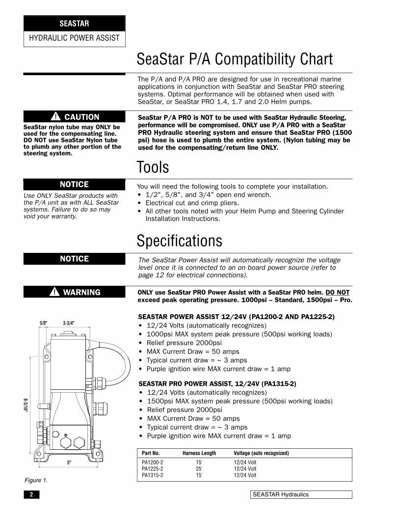
SEASTAR POWER ASSIST 12/24V (PA1200-2 AND PA1225-2)• 12/24 Volts (automatically recognizes)• 1000psi MAX system peak pressure (500psi working loads)• Relief pressure 2000psi• MAX Current Draw = 50 amps• Typical current draw = ~ 3 amps• Purple ignition wire MAX current draw = 1 amp
SEASTAR PRO POWER ASSIST, 12/24V (PA1315-2)• 12/24 Volts (automatically recognizes)• 1500psi MAX system peak pressure (500psi working loads)• Relief pressure 2000psi• MAX Current Draw = 50 amps• Typical current draw = ~ 3 amps• Purple ignition wire MAX current draw = 1 amp
2 SEASTAR Hydraulics
HYDRAULIC POWER ASSIST
SEASTAR
You will need the following tools to complete your installation.• 1/2", 5/8", and 3/4" open end wrench.• Electrical cut and crimp pliers.• All other tools noted with your Helm Pump and Steering Cylinder
Installation Instructions.
SeaStar P/A Compatibility Chart
Tools
The P/A and P/A PRO are designed for use in recreational marineapplications in conjunction with SeaStar and SeaStar PRO steeringsystems. Optimal performance will be obtained when used withSeaStar, or SeaStar PRO 1.4, 1.7 and 2.0 Helm pumps.
Specifications
3-3/4"
5"
8-3/16"
5/8"
SeaStar nylon tube may ONLY beused for the compensating line.DO NOT use SeaStar Nylon tubeto plumb any other portion of thesteering system.
SeaStar P/A PRO is NOT to be used with SeaStar Hydraulic Steering,performance will be compromised. ONLY use P/A PRO with a SeaStarPRO Hydraulic steering system and ensure that SeaStar PRO (1500psi) hose is used to plumb the entire system. (Nylon tubing may beused for the compensating/return line ONLY.
Use ONLY SeaStar products withthe P/A unit as with ALL SeaStarsystems. Failure to do so mayvoid your warranty.
The SeaStar Power Assist will automatically recognize the voltagelevel once it is connected to an on board power source (refer topage 12 for electrical connections).
NOTICE
NOTICE
ONLY use SeaStar PRO Power Assist with a SeaStar PRO helm. DO NOTexceed peak operating pressure. 1000psi – Standard, 1500psi – Pro.
WARNING
Part No. Harness Length Voltage (auto recognized)
PA1200-2 15' 12/24 VoltPA1225-2 25' 12/24 VoltPA1315-2 15' 12/24 Volt
CAUTION
Figure 1.

Power Assist for SeaStar Systems 3
HOW THE SYSTEM WORKS
SeaStar P/A (Power Assist) steering uses an electronically controlledhydraulic pump to provide "Power" for your SeaStar HydraulicSteering system.
The SeaStar P/A system is comprised of two circuits: a hand operatedmanual system, which is the control element, and a hydraulic powerpump, which is the working element.
The manual system consists of a helm pump with internal relief andcheck valves, as well as a built in reservoir. Two steering lines and acompensating line which provide a routing for fluid to transmit throughthe system, and a steering cylinder which moves the steering deviceon the boat from side to side.
The power system, is an electronically controlled hydraulic pump thatboosts the fluid being sent from the helm pump to the steering cylinder(this will result in much easier effort at the wheel—even when underheavy loads). A compensating line connects the P/A unit to the helmpump, allowing the P/A unit to share fluid with the helm reservoir.
The SeaStar P/A is compatible with multiple steering stations, andwith the use of an autopilot. In the event of a P/A power loss orfailure the hydraulic system will automatically revert to a manualhydraulic system.
H1 H2
C1 C2
H1 H2
C1 C2
HELMPUMP
STEERINGLINES
COMPENSATINGLINE
POWERASSISTUNIT
POWERASSISTUNIT
HELMPUMP
STEERINGLINES
COMPENSATINGLINE
SEASTAR OUTBOARDCYLINDER
TILLER ARM SEASTAR INBOARDCYLINDER
Typical installations shown (please refer to you cylinder installation manual for proper hoseinstallation diagrams).
Figure 2.

4 SEASTAR Hydraulics
THINGS YOU NEED TO KNOW
BEFORE STARTINGStudy this manual and the other manuals provided with your SeaStarSteering system carefully, and thoroughly to familiarize yourself with allof the components and their intended or required mounting locations.Ensure there is adequate space available for installation of allcomponents, hydraulic lines, and easy access for service. It is goodpractice to mount all components first, before running hoses. Thisallows port to port connection with less chance of an error. If youmust run hoses first, a system of marking the various lines must beused. ALL hose ends must be closed with tape or similar material toprevent contamination. Contamination is the most common causeof system failure.
Read ALL bold print text, notes and cautions. Reading them now willhelp prevent unexpected surprises during the installation.
SeaStar/SeaStar PRO Steering hoses CANNOT be cut. Cuttingthese hoses will render them useless. Failing to comply may resultin possible loss of steering causing property damage, personalinjury and/or death.
The SeaStar and SeaStar PRO Power Assist pump will automaticallyrecognize the power source output (12/24Volt). If connecting SeaStar,or SeaStar PRO Power Assist directly to the battery, the connectionMUST be fused in compliance with ABYC specifications.
WARNING
DO NOT use SeaStar Nylon tube with P/A unit, other than to plumbthe compensating line. Use of SeaStar or SeaStar PRO steering hoseis the ONLY hose recommended for use with the P/A unit.
CAUTION
Confirm that all components needed to complete the installation arepurchased, including: helm pump, steering cylinder, hoses, fluid, fittingsand pipe sealant such as Loctite PST, NEVER USE TEFLON TAPE.
CAUTION
The Power Assist Pump MUST be mounted in a DRY location. Caremust be taken to avoid any gathering of water/moisture on or aroundthe power assist unit. Failure to mount the Power Assist in a DRYlocation may result in irreparable damage to the unit and/or shortingof the battery which may result in property damage, personalinjury and/or death.
WARNING
Take EXTREME care not to allow any foreign material or contaminationto enter the hydraulic system. Contamination is the main causefor a hydraulic system to wear and or fail. Keep protective capson hose ends until ready to install onto the fitting.
CAUTION
NOTICE
These instructions have been made as complete as possible, but asbrief as practical. If you have any questions, contact your Distributoror SeaStar Solutions.

Filling and Purging Procedure• Refer to steps 1 through 5, located on page 15 of this manual.
DO NOT run the P/A unit until the SeaStarSteering System has been bled free of air. Failure to do somay result in non-repairable damage to the P/A unit.
Electrical Installation• Refer to page 12 of this manual for electrical connection.
Power Assist for SeaStar Systems 5
SYSTEM INSTALLATIONOVERVIEWSystem Installation• Install SeaStar Helm pump onto the dash using installation
instructions provided with your helm pump.
• Install Steering Cylinder into boat using the installationinstructions provided with your steering cylinder.
• The P/A unit will make a noise similar to that of an autopilot;this should be taken into consideration if installing the P/A unitinto a center consul and/or in an area where noise is preferredto be limited. Install the P/A unit in a vertical position (seediagram) as close the steering cylinder as possible.DO NOT mount the P/A unit in a horizontal position.
The P/A motor may be HOT to the touch, DO NOTmount P/A in an area where fabrics and/or any other flammablematerial may come in contact with the P/A motor.
• Install steering hoses using diagrams noted on page 6 throughpage 10, using your specific application.
The SeaStar PRO system must use SeaStar PROsteering hoses.
Due to the different cylinders options availablewith SeaStar Steering, be sure that you choose the correctinstallation diagram noted in this book.
Hoses MUST be at least 6’ in length from the powerassist to the helm pump, or, from the power assist to the cylinder(s).
NOTICE
NOTICE
CAUTION
WARNING
WARNING
CYLINDER
P/A UNIT
HELM
10° 10°
STEP 1
Final Purge and System Check• Turn ignition ON and continue with the filling and purging
instructions step 6 on page 18 of this manual
STEP 4
STEP 2
STEP 3
6 SEASTAR Hydraulics
SYSTEM INSTALLATION
SEASTAR POWER ASSIST
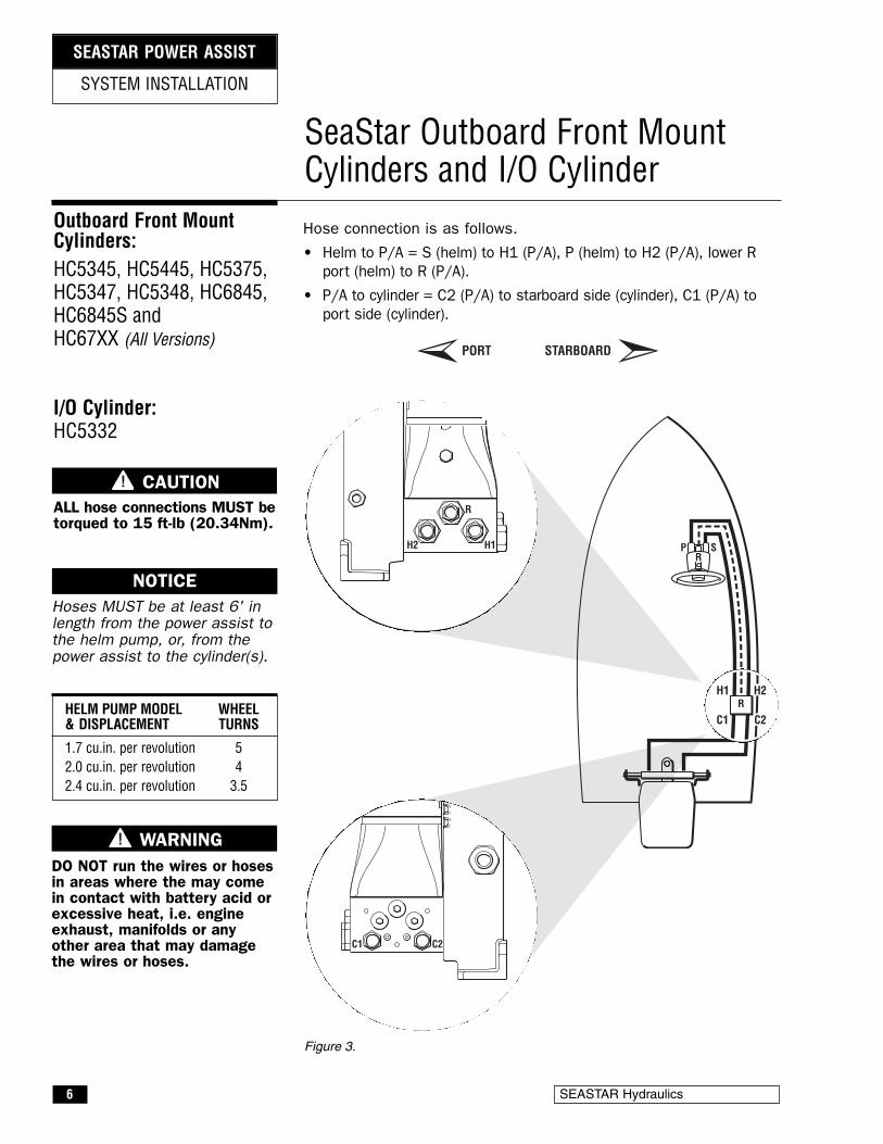
Hose connection is as follows.
• Helm to P/A = S (helm) to H1 (P/A), P (helm) to H2 (P/A), lower Rport (helm) to R (P/A).
• P/A to cylinder = C2 (P/A) to starboard side (cylinder), C1 (P/A) toport side (cylinder).
SeaStar Outboard Front MountCylinders and I/O Cylinder
PR
S
H1 H2
C1 C2R
Outboard Front MountCylinders:HC5345, HC5445, HC5375,HC5347, HC5348, HC6845,HC6845S andHC67XX (All Versions)
I/O Cylinder:HC5332
C1 C2
R
H1H2
PORT STARBOARD
Hoses MUST be at least 6' inlength from the power assist tothe helm pump, or, from thepower assist to the cylinder(s).
NOTICE
HELM PUMP MODEL WHEEL& DISPLACEMENT TURNS
1.7 cu.in. per revolution 52.0 cu.in. per revolution 42.4 cu.in. per revolution 3.5
Figure 3.
CAUTIONALL hose connections MUST betorqued to 15 ft-lb (20.34Nm).
DO NOT run the wires or hosesin areas where the may comein contact with battery acid orexcessive heat, i.e. engineexhaust, manifolds or anyother area that may damagethe wires or hoses.
WARNING
Power Assist for SeaStar Systems 7
H1 H2
C1 C2
PR
R
S
C1 C2
R
H1H2
PORT STARBOARD
PR
R
S
H1 H2
C1 C2
ALIGNMENTVALVE
SYSTEM INSTALLATION
SEASTAR POWER ASSIST
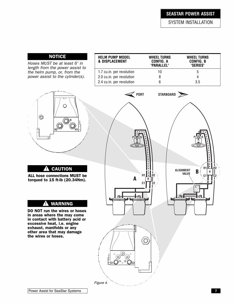
HELM PUMP MODEL WHEEL TURNS WHEEL TURNS& DISPLACEMENT CONFIG. A CONFIG. B
'PARALLEL' 'SERIES'
1.7 cu.in. per revolution 10 52.0 cu.in. per revolution 8 42.4 cu.in. per revolution 6 3.5
AB
Hoses MUST be at least 6' inlength from the power assist tothe helm pump, or, from thepower assist to the cylinder(s).
NOTICE
Figure 4.
CAUTIONALL hose connections MUST betorqued to 15 ft-lb (20.34Nm).
DO NOT run the wires or hosesin areas where the may comein contact with battery acid orexcessive heat, i.e. engineexhaust, manifolds or anyother area that may damagethe wires or hoses.
WARNING

8 SEASTAR Hydraulics
P SR
H1 H2R
C1 C2
C1 C2
R
H1H2
PORT STARBOARD
P S
H1 H2R
C1 C2
R
ALIGNMENTVALVE
SYSTEM INSTALLATION
SEASTAR POWER ASSIST
HELM PUMP MODEL WHEEL TURNS WHEEL TURNS& DISPLACEMENT CONFIG. C CONFIG. D
'PARALLEL' 'SERIES'
1.7 cu.in. per revolution 14.5 102.0 cu.in. per revolution 12.5 82.4 cu.in. per revolution 10.3 6
C D
Hoses MUST be at least 6' inlength from the power assist tothe helm pump, or, from thepower assist to the cylinder(s).
NOTICE
Figure 5.
CAUTIONALL hose connections MUST betorqued to 15 ft-lb (20.34Nm).
DO NOT run the wires or hosesin areas where the may comein contact with battery acid orexcessive heat, i.e. engineexhaust, manifolds or anyother area that may damagethe wires or hoses.
WARNING

HELM PUMP MODEL WHEEL TURNS WHEEL TURNS& DISPLACEMENT HC5370 HC5380
1.7 cu.in. per revolution 4.8/5.7 5.5/6.52.0 cu.in. per revolution 4.0/4.8 4.6/5.52.4 cu.in. per revolution 3.5/4.0 3.9/4.6
Power Assist for SeaStar Systems 9
Hose connection is as follows.
• Helm to P/A = S (helm) to H1 (P/A), P (helm) to H2 (P/A), lower Rport (helm) to R (P/A).
• P/A to cylinder = C1 (P/A) to starboard side (cylinder). C2 (P/A) toport side (cylinder).
SeaStar Outboard Side Mount andSplashwell Mount Cylinders
H1 H2
C1 C2
Side Mount Cylinder:HC5370 and HC5370-3
Splashwell Cylinder:HC5380 and HC5380-3
C1 C2
SYSTEM INSTALLATION
SEASTAR POWER ASSIST
PORT STARBOARD
R
H1H2
DO NOT use SeaStar PRO systemswith HC5370 side mount and/orHC5380 Splashwell mountcylinders as SeaStar PRO systemsare not compatible with anyunbalanced cylinder.
WARNING
Hoses MUST be at least 6' inlength from the power assist tothe helm pump, or, from thepower assist to the cylinder(s).
NOTICE
Figure 6.
Unbalanced cylinder will resultin unequal wheel turns.
NOTICE
CAUTIONALL hose connections MUST betorqued to 15 ft-lb (20.34Nm).
DO NOT run the wires or hosesin areas where the may comein contact with battery acid orexcessive heat, i.e. engineexhaust, manifolds or anyother area that may damagethe wires or hoses.
WARNING
10 SEASTAR Hydraulics
H1 H2
C1 C2
SYSTEM INSTALLATION
SEASTAR POWER ASSIST
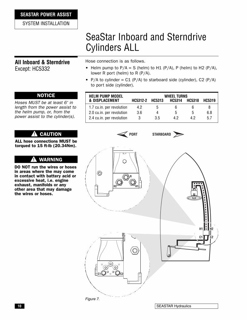
Hose connection is as follows.
• Helm pump to P/A = S (helm) to H1 (P/A), P (helm) to H2 (P/A),lower R port (helm) to R (P/A).
• P/A to cylinder = C1 (P/A) to starboard side (cylinder), C2 (P/A)to port side (cylinder).
SeaStar Inboard and SterndriveCylinders ALL
All Inboard & SterndriveExcept: HC5332
C1 C2
R
H1H2
PORT STARBOARD
Hoses MUST be at least 6' inlength from the power assist tothe helm pump, or, from thepower assist to the cylinder(s).
NOTICE
Figure 7.
HELM PUMP MODEL WHEEL TURNS& DISPLACEMENT HC5312-2 HC5313 HC5314 HC5318 HC5319
1.7 cu.in. per revolution 4.2 5 6 6 82.0 cu.in. per revolution 3.6 4 5 5 6.82.4 cu.in. per revolution 3 3.5 4.2 4.2 5.7
CAUTIONALL hose connections MUST betorqued to 15 ft-lb (20.34Nm).
DO NOT run the wires or hosesin areas where the may comein contact with battery acid orexcessive heat, i.e. engineexhaust, manifolds or anyother area that may damagethe wires or hoses.
WARNING
Power Assist for SeaStar Systems 11
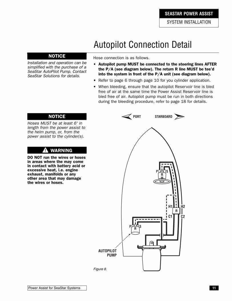
Hose connection is as follows.
• Autopilot pump MUST be connected to the steering lines AFTERthe P/A (see diagram below). The return R line MUST be tee'dinto the system in front of the P/A unit (see diagram below).
• Refer to page 6 through page 10 for you cylinder application.
• When bleeding, ensure that the autopilot Reservoir line is bledfree of air at the same time the Power Assist Reservoir line isbled free of air. Autopilot pump must be run in both directionsduring the bleeding procedure, refer to page 18 for details.
Autopilot Connection Detail
SYSTEM INSTALLATION
SEASTAR POWER ASSIST
PORT STARBOARD
Installation and operation can besimplified with the purchase of aSeaStar AutoPilot Pump. ContactSeaStar Solutions for details.
NOTICE
H1 H2
C1 C2
PR
R
S
P R S
AUTOPILOTPUMP
Hoses MUST be at least 6' inlength from the power assist tothe helm pump, or, from thepower assist to the cylinder(s).
NOTICE
Figure 8.
DO NOT run the wires or hosesin areas where the may comein contact with battery acid orexcessive heat, i.e. engineexhaust, manifolds or anyother area that may damagethe wires or hoses.
WARNING
12 SEASTAR Hydraulics
SYSTEM INSTALLATION
SEASTAR POWER ASSIST
Electrical Installation
Always use appropriate wiring terminals as per ABYC requirements.
Any electrical harness less than 72" in total length does not requirean overcurrent protection device as per ABYC E11.12 OVERCURRENTPROTECTION. Any harness length EXCEEDING 72" in total lengthMUST use an overcurrent protection device as per ABYC E11.12.Failure to NOT protect a harness may result in a fire and/or explosionleading to property damage, personal injury and/or death.It is good electrical practice to protect any harness, regardless oflength, with an overcurrent protection device. SeaStar Solutionsoffers two options, both of which meet ABYC E11.12 OVERCURRENTPROTECTION.
• HA1206, in-line MAXI fuse
• HA1207, battery mount fuse
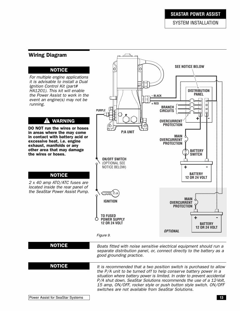
Refering to the wiring diagram on page 13 of this manual.
• Connect Red wire (+ positive) to the positive (+) supply
• Connect Black wire (– negative) to the negative (–) supply
• Connect purple wire (Power) to the ignition of the boat. Use of atwo-position ON/OFF switch is recommended, use a fuse protectedswitch ONLY. Use of this switch will allow the helmsman to turnthe Power Assist OFF in the case of power supply being limited.
NOTICE
If applicable, complete the wiring from the distribution panel to theboat battery in accordance to ABYC E-11.10 Load Calculation andE-11.16 System wiring.
NOTICE
WARNING
ALWAYS use ABYC compliant components in electrical installationsof the Power Assist and any other electrical device being installedon board the vessel. Failure to do so may result in a fire and/orexplosion leading to property damage, personal injury and/or death.
WARNING
The Power Assist wiring may be cutto length as per your installation.
NOTICE
Power Assist for SeaStar Systems 13
P/A UNIT
DISTRIBUTIONPANEL
BATTERYSWITCH
BRANCHCIRCUITS
MAINOVERCURRENT
PROTECTION
MAINOVERCURRENT
PROTECTION
OVERCURRENTPROTECTION
SEE NOTICE BELOW
OPTIONAL
+ -
BATTERY12 OR 24 VOLT
BATTERY12 OR 24 VOLT
+ -
+ -
– BLACK
PURPLE
+ RED
TO FUSEDPOWER SUPPLY12 OR 24 VOLT
IGNITION
ON/OFF SWITCH(OPTIONAL SEENOTICE BELOW)
SYSTEM INSTALLATION
SEASTAR POWER ASSIST
DO NOT run the wires or hosesin areas where the may comein contact with battery acid orexcessive heat, i.e. engineexhaust, manifolds or anyother area that may damagethe wires or hoses.
WARNING
NOTICEFor multiple engine applicationsit is advisable to install a DualIgnition Control Kit (part#HA1201). This kit will enablethe Power Assist to work in theevent an engine(s) may not berunning.
Wiring Diagram
2 x 40 amp ATO/ATC fuses arelocated inside the rear panel ofthe SeaStar Power Assist Pump.
NOTICE
It is recommended that a two position switch is purchased to allowthe P/A unit to be turned off to help conserve battery power in asituation where battery power is limited. In order to prevent accidentalP/A shut down, SeaStar Solutions recommends the use of a 12-Volt,15 amp, ON/OFF, rocker style or push button style switch. ON/OFFswitches are not available from SeaStar Solutions.
NOTICE
Boats fitted with noise sensitive electrical equipment should run aseparate distribution panel, or, connect directly to the battery as agood grounding practice.
NOTICE
Figure 9.
14 SEASTAR Hydraulics
Step 3
Step 1
Step 2
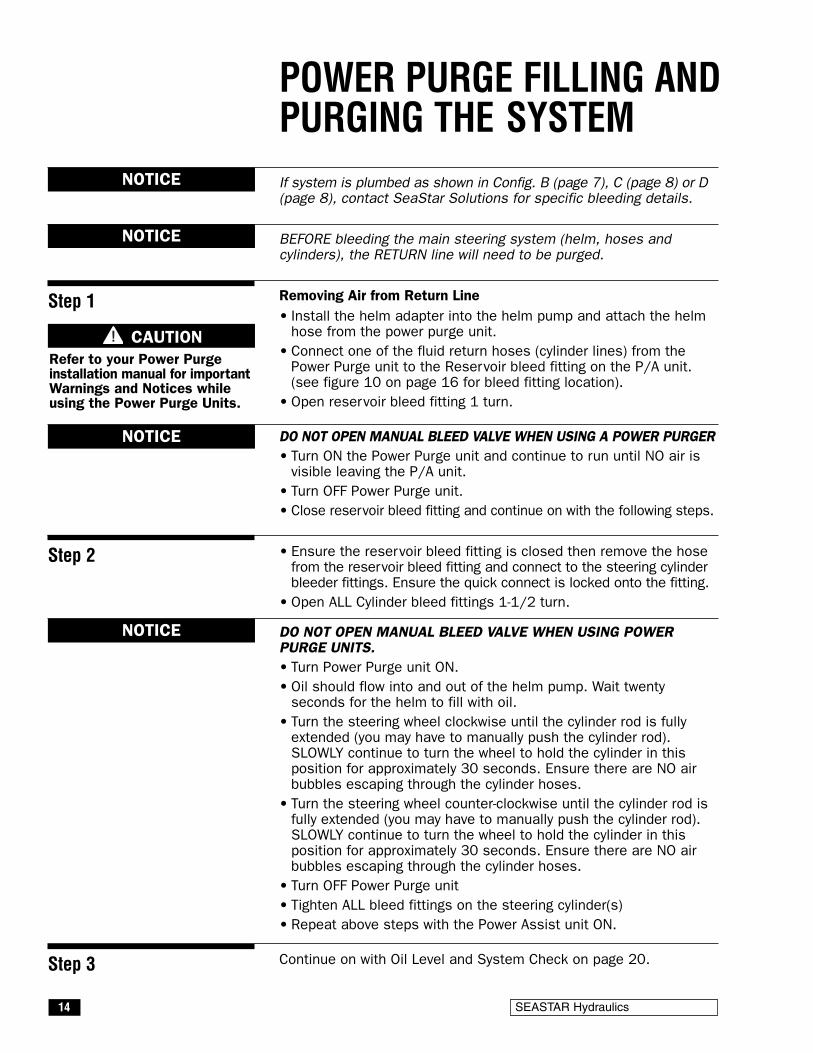
POWER PURGE FILLING ANDPURGING THE SYSTEMIf system is plumbed as shown in Config. B (page 7), C (page 8) or D(page 8), contact SeaStar Solutions for specific bleeding details.
BEFORE bleeding the main steering system (helm, hoses andcylinders), the RETURN line will need to be purged.
Removing Air from Return Line• Install the helm adapter into the helm pump and attach the helmhose from the power purge unit.
• Connect one of the fluid return hoses (cylinder lines) from thePower Purge unit to the Reservoir bleed fitting on the P/A unit.(see figure 10 on page 16 for bleed fitting location).
• Open reservoir bleed fitting 1 turn.
DO NOT OPEN MANUAL BLEED VALVE WHEN USING A POWER PURGER• Turn ON the Power Purge unit and continue to run until NO air isvisible leaving the P/A unit.
• Turn OFF Power Purge unit.• Close reservoir bleed fitting and continue on with the following steps.
• Ensure the reservoir bleed fitting is closed then remove the hosefrom the reservoir bleed fitting and connect to the steering cylinderbleeder fittings. Ensure the quick connect is locked onto the fitting.
• Open ALL Cylinder bleed fittings 1-1/2 turn.
DO NOT OPEN MANUAL BLEED VALVE WHEN USING POWERPURGE UNITS.• Turn Power Purge unit ON.• Oil should flow into and out of the helm pump. Wait twentyseconds for the helm to fill with oil.
• Turn the steering wheel clockwise until the cylinder rod is fullyextended (you may have to manually push the cylinder rod).SLOWLY continue to turn the wheel to hold the cylinder in thisposition for approximately 30 seconds. Ensure there are NO airbubbles escaping through the cylinder hoses.
• Turn the steering wheel counter-clockwise until the cylinder rod isfully extended (you may have to manually push the cylinder rod).SLOWLY continue to turn the wheel to hold the cylinder in thisposition for approximately 30 seconds. Ensure there are NO airbubbles escaping through the cylinder hoses.
• Turn OFF Power Purge unit• Tighten ALL bleed fittings on the steering cylinder(s)• Repeat above steps with the Power Assist unit ON.
Continue on with Oil Level and System Check on page 20.
NOTICE
NOTICE
NOTICE
NOTICE
CAUTIONRefer to your Power Purgeinstallation manual for importantWarnings and Notices whileusing the Power Purge Units.

Power Assist for SeaStar Systems 15
MANUAL FILLING ANDPURGING THE SYSTEM
Hydraulic Oil Requirements
NOTICE
NOTICE
NOTICE
CAUTION
These instructions show how to fill and purge a SeaStar SteeringSystem with the P/A unit installed. The same steps apply to ALLcylinders with the exception of which bleed fitting to open and closeand the direction the cylinder rod moves. These variations areshown in inset diagrams at each step. For multiple steering stations,start with the lowest station while going through Steps 1 – 7,repeat at each higher station until complete.
DO NOT turn ON P/A unit until manual portion is completed.
This procedure requires two people. One person may not be ableto remove all the air from the system, which will result in spongy,unresponsive steering.
During the entire filling procedure, oil MUST be visible in the fillertube. DO NOT allow oil level to disappear into the helm pump, asthis may introduce air into the system and increase your filling time.
2 bottles (2 quarts or liters) for single station and single cylindersystems. One additional bottle for each cylinder, helm, and orautopilot added to the system.
Oil can be re-used if filtered through a fine mesh screen such asthat used for gasoline. If unable to filter oil, an additional bottle offluid is required.
"Bleeder" refers to cylinder or P/A unit fitted with bleed fittings.Bleed fittings can be opened by unscrewing bleed nipple nut twoturns.
Protect your boating environment by ensuring that all used oil isdisposed of properly.
Read First
Single Station One CylinderNOTICE BEFORE bleeding the main steering system (helm, hoses and
cylinders), the RETURN line will need to be purged.
Removing Air From Return Line
• Install the fill tube and fluid fill bottle into the helm pump.
Filling the helm full of fluid prior to connecting the filler tube and oilbottle will decrease purge time.
• Open the manual bleed valve (see Figure 10) and reservoir bleedfitting (see Figure 10) on the power assist unit. The manual bleedvalve should be opened two full turns.
Step 1
NOTICE

16 SEASTAR Hydraulics
FILLING AND PURGING
SEASTAR POWER ASSIST
Step 2
OPEN RIGHT SIDEBLEEDER
TURNCLOCKWISE
OPEN LEFT SIDEBLEEDER
TURNCLOCKWISE
• Turn the steering wheel clockwise until the cylinder rod is fullyextended on the right side of the cylinder.
• Open bleed fitting as per your installation.
Outboard Front Mount & HC5332 Cylinder Side Mount / Splashwell Mount Cylinder All Balanced Cylinder. Inboard & Sterndrive Cylinders
OPEN LEFT SIDEBLEEDER
TURNCLOCKWISE
R
H1H2
MANUAL BLEED VALVE
RESERVOIR BLEED FITTING
FILLER PLUG(REMOVED)
PUSH PIN
FILLER KIT
HELM FILL PORT
DO NOT LETOIL LEVELFALL BELOWTHIS POINT
• Fill helm with fluid, then, turn steering wheel to the starboard sideuntil a steady stream of "air-free" oil comes out of the reservoirbleed fitting on the Power Assist Unit.
• Close reservoir bleed fitting.
• Continue to turn the wheel to starboard another 15 turns after closingthe reservoir bleed fitting and prior to closing the manual bleed valve.
• Close manual bleed valve and continue with Steps 2 – 5.
Figure 10.

Power Assist for SeaStar Systems 17
FILLING AND PURGING
SEASTAR POWER ASSIST
Step 3
TURN COUNTER-CLOCKWISE
CLOSE RIGHTSIDE BLEEDER
CLOSE LEFT SIDEBLEEDER
TURN COUNTER-CLOCKWISE
• Holding the cylinder body (Front Mount cylinder) or rod (SideMount cylinder) to prevent the body/rod from moving, turn thesteering wheel counter-clockwise until a steady stream of air freeoil comes out of the bleeder. (Drain approx. 1/2 bottle of oil or asrequired).
Do not use anything other than your hands to restrain thecylinder body/rod.
• While continuing to turn the wheel close the bleed fitting for yourapplication and let go of the cylinder body/rod.
Outboard Front Mount & HC5332 Cylinder Side Mount / Splashwell Mount Cylinder All Balanced Cylinder. Inboard & Sterndrive Cylinders
TURN COUNTER-CLOCKWISE
CLOSE LEFT SIDEBLEEDER
Step 4
TURN COUNTER-CLOCKWISE
OPEN LEFTSIDE BLEEDER
OPENRIGHTSIDEBLEEDER
TURN COUNTER-CLOCKWISE
• Continue turning the steering wheel counter-clockwise until the cylinderrod is fully extended to the left. (Steering wheel will come to a stop).
• Open bleed fitting as per your installation.
Outboard Front Mount & HC5332 Cylinder Side Mount / Splashwell Mount Cylinder All Balanced Cylinder. Inboard & Sterndrive Cylinders
TURN COUNTER-CLOCKWISE
OPENRIGHTSIDEBLEEDER

18 SEASTAR Hydraulics
FILLING AND PURGING
SEASTAR POWER ASSIST
Step 5
TURN CLOCKWISE
CLOSE LEFT SIDEBLEEDER
TURN CLOCKWISE
• Holding the cylinder body (Front Mount cylinder) or rod (Side Mountcylinder) to prevent the body/rod from moving, turn the steeringwheel clockwise until a steady stream of air free oil comes out ofthe bleeder.
• While continuing to turn the wheel close the bleed fitting for yourapplication and let go of the cylinder body/rod.
CLOSERIGHT SIDEBLEEDER
Outboard Front Mount & HC5332 Cylinder Side Mount / Splashwell Mount Cylinder All Balanced Cylinder. Inboard & Sterndrive Cylinders
TURN CLOCKWISE
CLOSERIGHT SIDEBLEEDER
Step 6 • Complete electrical connections as outlined in your InstallationOwner’s Manual.
• Repeat Steps 2 – 5 of purging instructions with the P/A unit "ON"
Be sure to remove ALL air from the autopilot reservoir line.
If the system has an autopilot installed, ensure that the autopilotpump is run for at least 10 seconds in both directions during Step 3and Step 5.
NOTICE
CAUTION Prior to operating system, perform Oil Level System Check, referto page 20.

Power Assist for SeaStar Systems 19
FILLING AND PURGING
SEASTAR POWER ASSIST
Perform Steps 1 – 6 at stationno. 1. Then repeat Steps 2 – 5at station no. 2.
Note: Refer to Oil Level &System Check on page 20.
Twin Station Single CylinderSTATION NO.2
STATION NO.1
CYLINDER
P/A UNIT
Follow same procedure asinstructed for single station-twincylinders, beginning at stationno. 1, and repeat entireprocedure at station no. 2.
Note: Refer to Oil Level &System Check on page 20.
Twin Station Twin Cylinder
CYLINDER NO.2 CYLINDER NO.1
STATION NO.2
STATION NO.1
CYLINDER NO.2 CYLINDER NO.1
When performing Steps 2 – 5,perform instructions in eachstep first on cylinder no. 1 andthen on cylinder no. 2, beforeproceeding to the next step. ie:Perform instructions referringto right side of cylinder first oncylinder no. 1 and then oncylinder no. 2.
Note: Refer to Oil Level &System Check on page 20.
Single Station Twin Cylinder
P/A UNIT
P/A UNIT

20 SEASTAR Hydraulics
FILLING AND PURGING
SEASTAR POWER ASSIST
At this time the steering system must be checked for properconnections hose and fittings, possible leaks, and air removal.Please complete the following steps with the P/A Unit OFF.
• Turn steering wheel to hard over, then force the wheel another onequarter to one half turn past the stop point. Check the followingareas for evidence of a leak.
- Helm fitting connections.
- P/A fitting connections
- Cylinder fitting connections
• Repeat above steps to the other steering direction.
• Any sign of a leak MUST be repaired prior to operating the boat.
• While turning steering wheel observe fluid level in the helm pump.If fluid level drops and rises as the wheel is being turned there isstill air in the system. Complete bleeding instructions again untilno obvious fluid level change is noticed.
Helms mounted with the wheel shaft completely horizontal must befilled to the bottom of the filler hole at all times. Do NOT allow thefluid level to drop more than one-quarter inch below the filler hole.
Helms mounted on a 20 degree angle or with the wheel shaft verticalMUST have the fluid level within 1/2" of the filler hole, refer to thediagram below.
Oil Level and System Check
NOTICE
NOTICE
1/2"(12.5mm)
VERTICAL
20∞
Figure 11.

Power Assist for SeaStar Systems 21
TROUBLESHOOTING GUIDE
FAULT CAUSE SOLUTION
1. P/A unit does notturn on.
Blown Fuse/Breaker
Wrong electrical connections
Replace 'external' fuse if blown first.Replace 'internal' fuse if blown second.Or, reset breaker.
2 x 40 amp ATO/ATC fuses arelocated inside the rear panel of the SeaStarPower Assist Pump.
If it is necessary to replace thefuse(s) in the Power Assist Unit, ensurethe Power Assist Unit is turned OFF.
Refer to wiring diagram and location offuse on on page 13.
2. Turns the wrong way Lines reversed Review the plumbing diagrams for your systemnoted on page 6 through page 10, confirmthat your hoses are hooked up correctly.
3. Wheel is bumpy Air in system Re-Bleed. Concentrate on remaining air inthe P/A unit.
Autopilot has not been bled as per instructions.
4. Helm locks up in bothdirections
Hoses installed in the wrongports.
Kinked or collapsed line
Review the plumbing diagrams for your systemnoted on page 6 through page 10, confirmthat your hoses are hooked up correctly.
Check ALL lines for sign of a collapsed orkinked line.
5. Helm only turns in onedirection and free wheelsin the other
Port or Starboard line isconnected to the reservoir Rport on the P/A unit.
Review the plumbing diagrams for your systemnoted on page 6 through page 10, confirmthat your hoses are hooked up correctly.
6. Steering is very hard (stiff) P/A unit is not turned on.
Partially kinked or collapsedline.
H1, H2 or R port screenfilters are plugged withcontamination.
See fault #1
Check ALL lines for a sign of a collapsedor kinked line
Remove H1, H2 and R hose and fittings.Clean screens located in the adapter fittings.
7. No Power Assist, Lights areblinking.
Note sequence of blinkinglights
See page 22 for details
NOTICE
WARNING
8. After hitting hard over and/orrunning at high loads with theSeaStar PRO Power Assist,the effort at the wheelincreasing dramatically.
Helm is super charging Super charging is a normal occurrencewith ALL PRO systems, while running athigher loads and/or hitting the hard overpoint. This should not be taken as a faultin the system.

22 SEASTAR Hydraulics
9. The power assist unit isreally hot to the touch.
Motor operating This is a normal occurrence with the PowerAssist unit; mount the P/A in an areawhere it can not easily be handled andaway from flammable materials.
Whenever a solution calls for the removal from vessel and/ordismantling of steering system components, such work must ONLYbe carried out by a qualified marine hydraulic mechanic. SeaStarSolutions offers this information as a guide ONLY and is notresponsible for any consequences resulting from incorrect repairs.When in doubt, contact your parts distributor or SeaStar Solutionsfor assistance.
WARNING
FAULT CAUSE SOLUTION
10. Lock to lock wheel turnsare different with the powerassist “off” than with thepower assist “on”.
Hitting hard-over causing hoseexpansion.
Power assist is pressurizingsystem.
This is a normal occurrence when usingthe power assist system.
This is a normal occurrence when using apower assist.
11. Noise interference throughradio, VHF, stereo or sonardevices when the powerassist is turned ON andoperating.
Power Assist wired to samedistribution panel as noisesensitive equipment.
Sensitive equipment is notmeeting immunity standards.
Wire Power Assist to separate distributionpanel or direct to the battery.
Add noise suppression/isolation betweenpower source and sensitive equipment.
The Green and Red lights are used to show the status of the SeaStarPower Assist Units. Below is a quick list as to what the lights referto. Any fault within the Power Assist Unit will be acknowledged viathe RED light flashing in the sequences noted below.
• GREEN. Steady (no flash)Normal operation.
• RED. Two flashes, long pauseStandby mode, lack of calibration.SOLUTION: Contact SeaStar Solutions.
• RED. Three flashes, long pauseCalibration mode.SOLUTION: Turn OFF ignition, after one minute, turn ignition ON.If problem persists, contact SeaStar Solutions.
• RED. Four flashes, long pauseOvervoltage mode.SOLUTION: check ignition and battery voltage. MUST be lessthan 32Volts, correct as required.
NOTICE

Power Assist for SeaStar Systems 23
ACCESSORIES
The Dual Ignition Control Kit is designed to connect the P/A unit'signition wire to two engines allowing one engine to be turned offand retain power assist control.
SeaStar P/A Dual IgnitionControl KitPart# HA1201
SeaStar®/BayStar™ Power Purge Jr. is the quickest way to bleed aSeaStar®/ BayStar™ system in the field and assure a rock-solidsteering feel every time!
SeaStar Power Purge JR.Part# HA5445-2
• Steering feel is solid every time• Complete Fill & Purge in 10
minutes or less• Fast and efficient• Easy to operate• Screens contaminants from oil• Quick connect fittings
• Convenient portable size• Convenient electrical hook-up
utilizing 12 volt boat battery• Optional Dual Cylinder Purging
Kit HA5461 available• Optional 50’ Hose Extension
Kit HA5462, for longer runs
Advantages:
For each and every engine fittedafter two (triples, quads... etc.),you will require one moreHA1201 kit per engine beingadded.
NOTICEP/A UNIT
ENGINE #3
ENGINE #1
ENGINE #2
Figure 12.
Figure 13.

24 SEASTAR Hydraulics

Power Assist for SeaStar Systems 25�
2-1/2"
5"(127 mm)
5-.42"
(138m
m)
1-3/8"(64 mm)
TOP OF POWERASSIST UNIT
2 x .22"(35 mm)
Floor MountingTemplate
If printing, or photocopying fromthis page. Using a ruler, confirmthat the measurements shownon the print out are as stated on
this page BEFORE drilling.
NOTICE

26 SEASTAR Hydraulics

Power Assist for SeaStar Systems 27�
5.0"
3.7"(94 mm)
8.19"
(208m
m)
(127 mm)
4 x .22"
FRONT OF POWERASSIST UNIT
Wall MountingTemplate
If printing, or photocopying fromthis page. Using a ruler, confirmthat the measurements shownon the print out are as stated on
this page BEFORE drilling.
NOTICE

28 SEASTAR Hydraulics

Power Assist for SeaStar Systems 29
Statement of Limited Warranty
Return Goods Procedure
We warrant to the original retail purchaser that Marine CanadaAcquisition Inc. DBA SEASTAR SOLUTIONS (herein forward referredto as SeaStar Solutions) products have been manufactured free fromdefects in materials and workmanship. This warranty is effective fortwo years from date of purchase, excepting that where SeaStarSolutions products are used commercially or in any rental or incomeproducing activity, then this warranty is limited to one year from thedate of purchase.
We will provide replacement product without charge, for any SeaStarSolutions product meeting this warranty, which is returned (freightprepaid) within the warranty period to the dealer from whom suchproduct were purchased, or to us at the appropriate address. In sucha case SeaStar Solutions products found to be defective andcovered by this warranty, will be replaced at SeaStar Solutions'option, and returned to the customer.
The above quoted statement is an extract from the complete SeaStarSolutions products warranty statement. A complete warranty policyis available in our SeaStar Solutions products catalogue.
Prior to returning product to SeaStar Solutions under warranty,please obtain a Return Goods Authorization number (claim number).
Be sure to label the goods with:a) the name and address of the sender, andb) the return goods authorization number (claim number)
Please address the returned goods as follows:
From U.S.A.RGA # ?SeaStar Solutionsc/o UPS–Supply Chain Solutions Inc.Door A371201 C Street NW, Auburn, WA,98001
Phone: 604-248-3858
email: [email protected]
Hours: Monday - Friday 05:00 – 15:30 PST
Web: www.seastarsolutions.com
Technical Support
From CanadaRGA # ?SeaStar Solutions3831 No. 6 RoadRichmond, B.C.Canada V6V 1P6

30 SEASTAR Hydraulics

SEASTAR SOLUTIONS3831 NO.6 ROADRICHMOND, B.C.CANADA V6V 1P6
FAX 604-270-7172
www.seastarsolutions.com
© 2007 MARINE CANADA ACQUISITION INC.DBA SEASTAR SOLUTIONS
PRINTED IN CANADA
2000–09/14
ISO 10592
FORM NO. 298403 Rev. F