installation instructions - rheem 325 installation and users...installation instructions air sourced...
TRANSCRIPT

This water heater must be installed and serviced by an authorised person. Please leave this guide with the householder.
Installation Instructions
Air Sourced Split
Heat Pump Module
MPs Series

PATENTS This water heater may be protected by one or more patents or registered designs
in the name of Rheem Australia Pty Ltd.
TRADE MARKS ® Registered trademark of Rheem Australia Pty Ltd.
™ Trademark of Rheem Australia Pty Ltd.
Note: Every care has been taken to ensure accuracy in preparation of this publication. No liability can be accepted for any consequences,
which may arise as a result of its application.
Notice to Victorian Customers from the Victorian Plumbing Industry Commission.
This water heater must be installed by a licensed person as required by the Victorian Building Act 1993.
Only a licensed person will give you a Compliance Certificate, showing that the work complies with all the relevant standards. Only a licensed person will have insurance protecting their workmanship for 6 years. Make sure you use a licensed person to install this water heater and ask for your Compliance Certificate.

3
CONTENTS
HOUSEHOLDER – This installation instruction booklet is intended for the installer but you may find it of interest.
Installation .............................................................................................. 4
Heat Pump And Tank Assembly ......................................................... 11
Connections – Electrical ..................................................................... 30
Commissioning .................................................................................... 32
Water Supplies ..................................................................................... 36
Warranty Note ...................................................................................... 39

4
INSTALLATION
THE HEAT PUMP MODULE OF THIS WATER HEATER IS FOR OUTDOOR INSTALLATON ONLY. The installation must comply with the requirements of AS/NZS 3500.4, AS/NZS 3000 and all local codes and regulatory authority requirements. In New Zealand, the installation must conform with Clause G12 of the New Zealand Building Code. This water heater is recommended for connection to a 24 hour per day power supply. All packaging materials must be removed from the heat pump module prior to its installation. This includes the removal of the cardboard base of the carton from the underside of the module.
STORAGE TANK AND HEAT PUMP MODULE
The heat pump water heater is made of two main components, the storage tank and the heat pump module. For transport and handling (weight) purposes both items are shipped separately. The water heater must not be operated until both components are installed, connected and purged of air. Refer to “Heat Pump and Tank Assembly” on page 11. Take care when handling the heat pump module. The jacket of the heat pump module needs to be handled gently so as not to cause damage. Care must be taken during transportation and handling. Do not lay the heat pump module down and do not tilt the heat pump module more than 30° from the vertical. This will displace the compressor lubricating oil. If the heat pump module has been tilted more than 30° from the vertical during handling, it will need one hour to drain back before the power to the water heater can be switched on, otherwise damage to the compressor may result.
Warning: This heat pump module is designed to be installed with a purpose
built water heater storage tank and may not be used for any other purpose.

INSTALLATION
5
HEAT PUMP MODULE LOCATION
The heat pump module is suitable for outdoor installation only. The heat pump module‟s position is to be chosen with noise, safety and service in mind. Make sure people (particularly children) will not accidentally touch the air inlet louvres and outlet grille and that they are clear of obstructions and shrubbery. It is advisable to install the heat pump module away from bedroom or living room windows as the system components can generate a level of noise whilst they are operating. Consider the location in relation to neighbours‟ bedrooms and living room windows. Clearance must be allowed for servicing of the heat pump module. It must be accessible without the use of a ladder or scaffold. Make sure the heat pump module‟s top and front covers and system controls can be removed for service. You must be able to read the information on the rating plate of the heat pump module. Remember you may have to remove the heat pump module later for servicing. It is recommended the heat pump module be installed at ground or floor level and must stand vertically upright. The heat pump module must be installed against a wall and on a level slab or solid base with a minimum size of 600 mm wide x 600 mm deep. The heat pump module must be secured using the wall bracket and four feet brackets provided. Refer to “Heat Pump and Tank Installation” on page 11. A clearance of at least 300 mm is required perpendicular from both the side air inlet louvres and the outlet grille to any wall or obstruction. Refer to the dimensions diagram on page 9. The heat pump storage tank and heat pump module must be installed within four (4) metres of each other. The heat pump flow and return pipes connecting the heat pump storage tank to the heat pump module must not exceed four (4) metres in length each and must not contain more than 4 x 90º bends each. All changes in direction of the pipe work must be made using bends. The pipe work should not contain elbows. The water heater must not be installed in an area with a corrosive atmosphere where chemicals are stored or where aerosol propellants are released. Remember the air may be safe to breathe, but the chemicals may attack the materials used in the heat pump system.

INSTALLATION
6
Note These instructions cover only the installation of the heat pump module and the connections made between the heat pump module and storage tank. Refer to the Owner‟s Guide and Installation Instructions supplied with the storage tank for further information including:
where and how to locate the heat pump water heater
the dimensions of the heat pump water heater and any clearances required from surrounding objects
how to connect the heat pump water heater to the electricity supply and to the plumbing system
how to operate the heat pump water heater
what to do if something goes wrong.
FREEZE PROTECTION
The water heater has a freeze protection system. The freeze protection system will protect the water heater from damage, by preventing ice forming in the waterways of the water heater, in the event of freezing conditions occurring. If the ambient air temperature falls below 4°C and the heat pump module is not operating, the system will operate the circulator periodically. During this freeze protection cycle, the circulator will operate for three (3) minutes and then rest for fifteen (15) minutes, before the cycle is recommenced. Water is circulated from the storage tank through the heat pump circuit, to prevent freezing in the connecting pipe work and heat pump module.
Warning: In areas where the ambient air temperature may fall below 0°C, power must be available to the water heater at all times to prevent freezing in the heat pump circuit. The system must be installed with the heat pump circuit hot and cold pipes fully insulated with closed cell polymer insulation with a minimum thickness of 13 mm. Thicker insulation may be required to comply with the requirements of AS/NZS 3500.4. The water heater has NO WARRANTY for freeze damage if the heat pump circuit hot and cold pipes are not suitably insulated or if power is unavailable at the water heater.

INSTALLATION
7
MAINS WATER SUPPLY
Where the mains water supply pressure exceeds that shown in the table below, an approved pressure limiting valve is required. Refer to the Owner‟s Guide and Installation Instructions supplied with the storage tank for the position of the pressure limiting valve.
Model 270, 325, 410
Relief valve setting 1000 kPa
Expansion control valve setting * 850 kPa
Max. mains supply pressure
With expansion control valve 680 kPa
Without expansion control valve 800 kPa
Min. mains supply pressure 200 kPa
* Expansion control valve not supplied with the water heater.
A minimum water supply pressure of 200 kPa is required to enable the heat pump circulator and heat pump system to operate effectively.
TANK WATER SUPPLY
If the water heater is supplied with water from a tank supply and a minimum water supply pressure of 200 kPa at the water heater cannot be achieved, then a pressure pump system must be installed to allow the heat pump circulator to operate and avoid air locks in the circuit. Care must be taken to avoid air locks. The cold water line from the supply tank should be adequately sized and fitted with a full flow gate valve or ball valve.
PURGING AIR FROM THE SYSTEM
The water heater system must be purged of air prior to operation, using the manual air bleed valve supplied on the storage tank. Failure to bleed the air out of the connecting pipe work and heat pump module will result in non-operation of the circulator and failure of the heat pump to operate due to overheating.

INSTALLATION
8
CONDENSATE DRAIN
A drain line must be fitted to the heat pump module‟s condensate drain to carry the discharge clear of the water heater. The drain line can be extended using 12 mm rigid poly hose or conduit. The pipe work from the condensate drain should be as short as possible, and fall all the way from the water heater with no restrictions. It should have no more than three right angle bends in it. The outlet of the drain line must be in such a position that flow out of the pipe can be easily seen - but arranged so water discharge will not cause damage or nuisance. The condensate drain line must not be connected to the relief valves drain lines but may discharge at the same point.
WARNING
This water heater is only intended to be operated by persons who have the experience or the knowledge and the capabilities to do so. This water heater is not intended to be operated by persons with reduced physical, sensory or mental capabilities, i.e. the infirm, or by children. Children should be supervised to ensure they do not interfere with the water heater. This water heater uses 240 V AC electrical power for operation of the control systems and the electrically operated components. The removal of the access cover(s) will expose 240 volt wiring. They must only be removed by an authorised or qualified person.
ENVIRONMENT
At the end of the service life of the heat pump water heater and prior to the water heater being disposed of, a person qualified to work with refrigerants must recover the refrigerant from within the sealed system. The refrigerant must not be vented to atmosphere. Phone your nearest Rheem Service Department or Accredited Service Agent to arrange for an inspection.

INSTALLATION
9
DIMENSIONS AND TECHNICAL DATA
HEAT PUMP DIMENSIONS - REMOTE
325 LITRE STORAGE TANK
HEAT PUMP DIMENSIONS - REMOTE
325 LITRE STORAGE TANK
elevation plan view
Heat pump module models 180536 (R) 180540 (E)
Maximum rated power input watts 3600
Rated heat pump power input watts 800
Booster element ratings kW 2.4, 3.6
Refrigerant type R134a
Refrigerant circuit pressure kPa 3000
Mass heat pump module kg 46
Storage tank capacity litres 270 325 410
Boost capacity* litres 180 180 200
Mass tank empty kg 71 88 112
Mass tank full kg 341 413 522
* The boost capacity of a low watts density or other than a 2.4 kW or 3.6 kW heating unit, if used, is 100 litres (270 and 325 litre storage tanks) or 125 litres (410 litre storage tank). Technical data is subject to change.

INSTALLATION
10
TYPICAL INSTALLATON – OUTDOOR LOCATION
TYPICAL INSTALLATION
HEAT PUMP WATER HEATER - REMOTE

11
HEAT PUMP AND TANK ASSEMBLY
STORAGE TANK AND HEAT PUMP MODULE
The heat pump water heater is made of two main components, the storage tank and the heat pump module. For transport and handling (weight) purposes both items are shipped separately. The water heater must not be operated until both components are installed, connected and purged of air. Note: The heat pump flow and return pipes connecting the heat pump storage tank to the heat pump module must not exceed four (4) metres in length each and must not contain more than 4 x 90º bends each. All changes in direction of the pipe work must be made using bends. The pipe work should not contain elbows.
HEAT PUMP MODULE
The heat pump module is shipped in a box containing two hand holes to facilitate easy handling and lifting. The heat pump module must be installed against a wall and on a level slab or solid base with a minimum size of 600 mm wide x 600 mm deep. The heat pump module must be secured using the wall bracket and four feet brackets provided. CAUTION: The heat pump module weighs approximately 46 kg. Use the hand holes provided in the sides of the packaging. Good lifting practice should be followed. There are two flexible braided hoses provided inside the heat pump module. The flexible braided hoses are removed from the module and fixed to the outside of the heat pump module jacket using the brackets provided during the assembly procedure. The flow and return pipe work from the heat pump storage tank connects to these hoses. A cable set housed in conduit is provided inside the heat pump module. The cable set is removed from the module and fixed to the outside of the heat pump jacket using the brackets provided during the assembly procedure. The cable set connects to the heat pump storage tank.
STORAGE TANK
The storage tank must be fully supported by a level slab or solid base. There are two water fittings located on the side of the storage tank to which the flow and return pipe work from the heat pump module is connected during the assembly procedure. The cable set from the heat pump module is also connected to the storage tank during the assembly procedure.

HEAT PUMP AND TANK ASSEMBLY
12
storage tank heat pump module
KIT
There is a kit supplied with the heat pump module (PN 290123). The components supplied in the kit are:
290123 Kit Installation Heat Pump Module Split Qty
126574 Installation instructions heat pump module split 1
126571 Easy start guide instructions heat pump module split 1
220522 Drain hose tube ½” ID x 380 long 1
080189 Hose spring clamp – ½” ID 1
052165 Saddle clamp 1
080021 Screw phillips pan head No. 8 x 13 zinc plated black 2
108392 Bracket hose mount 1
108393 Bracket hose clamp 1
080059 Nut speed fasteners No. 6 1219 4
052160 Conduit clamp 1
080031 Screw phillips pan head No 8 x 13 7
- Dynabolt Z passivated anchor 8 mm x 40 mm (M6) 4
108399 Bracket wall 1
- Wall plug 8 mm x 25 mm 1
080117 Screw button head 8G x 15 x 25 zinc plated 1
088189 Tube bush fitting connector ½” M x ½” OD reliance W120 2
- Cable tie black UV rated nylon 200 x 4.8 mm 4

HEAT PUMP AND TANK ASSEMBLY
13
ASSEMBLY PROCEDURE
Warning: The heat pump must be assembled, plumbed, filled with water
and purged of air prior to power being connected and switched on. The following procedure is to be followed to install the heat pump module in position and connect to the heat pump storage tank.
1. Heat Pump Storage Tank: Remove all packaging including the carton base from the storage tank and position in its intended location, supported by a level slab or solid base.
The cold and hot water connections may be on either the left or right hand side, and should be parallel to the wall.
The heat pump flow and return connections are on the opposite side of the heat pump storage tank to the cold and hot water connections. The heat pump storage tank should be orientated so these connections face the location of the heat pump module. This will allow for an easier and neater installation of the heat pump flow and return pipe work.
2. Heat Pump Module: Remove all packaging including the carton base from the heat pump module.
Set aside the carton liner piece marked “(DO NOT REMOVE)” as this contains the template which is required to locate the position of the holes to be drilled to connect the heat pump module bracket to the wall and the heat pump feet to the supporting base.
Remove the heat pump module‟s rear access panel from the carton liner and set aside.
3. Kit Bag and Cable Set: Through the opening at the rear of the heat pump module:
Remove the kit bag and set aside
Withdraw the cable set and the two flexible braided hoses.

HEAT PUMP AND TANK ASSEMBLY
14
4. Drain Hose: Retrieve the drain hose, hose clamp, saddle and two black screws from the kit bag.
Feed the hose through the penetration on the side of the heat pump module
Slip the hose clamp over the upper end of the hose within the heat pump module
Push the hose over the spigot on the condensate tray located below the evaporator
Secure the hose to the spigot with the hose clamp
Extend the hose away from the base of the heat pump module using standard 12 mm irrigation fittings
Secure the hose to the side of the heat pump module with the saddle, using the two black screws.
Step 4
feed hose through secure hose secure hose penetration to the spigot with saddle

HEAT PUMP AND TANK ASSEMBLY
15
5. Heat Pump Module Location: Select the location for the heat pump module.
The heat pump module must be positioned such that there is a clearance of at least 300 mm perpendicular from the air inlet louvres and the outlet grilles.
The heat pump module must be installed against a wall and on a level slab or solid base with a minimum size of 600 mm wide x 600 mm deep.
The heat pump flow and return lines connecting the heat pump storage tank to the heat pump module must not exceed four (4) metres in length each and must not contain more than 4 x 90º bends each. All changes in direction of the pipe work must be made using bends. The pipe work should not contain elbows.
Ensure the cable set reaches the storage tank with sufficient length to enable it to be saddle clamped to the wall.
Ensure the maximum length of the heat pump flow and return pipe work and the maximum number of 90° bends will not be exceeded.
HEAT PUMP DIMENSIONS - REMOTE
325 LITRE STORAGE TANK
Step 5 select location for heat pump module
and allow for at least 300 mm ventilation clearance
HEAT PUMP AND TANK ASSEMBLY
16
6. Connection Side for Heat Pump Module: Select which side, either the left or right hand side, of the heat pump module will be used to connect the heat pump flow and return lines to the flexible braided hoses.
It is recommended to select the side of the heat pump module which is closest to the heat pump storage tank. This will allow for an easier and neater installation of the heat pump flow and return pipe work.
The cable set should also be run from this side of the heat pump module to the heat pump storage tank.
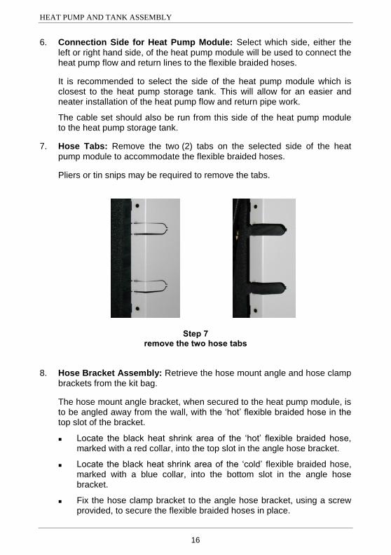
7. Hose Tabs: Remove the two (2) tabs on the selected side of the heat pump module to accommodate the flexible braided hoses.
Pliers or tin snips may be required to remove the tabs.
Step 7 remove the two hose tabs
8. Hose Bracket Assembly: Retrieve the hose mount angle and hose clamp brackets from the kit bag.
The hose mount angle bracket, when secured to the heat pump module, is to be angled away from the wall, with the „hot‟ flexible braided hose in the top slot of the bracket.
Locate the black heat shrink area of the „hot‟ flexible braided hose, marked with a red collar, into the top slot in the angle hose bracket.
Locate the black heat shrink area of the „cold‟ flexible braided hose, marked with a blue collar, into the bottom slot in the angle hose bracket.
Fix the hose clamp bracket to the angle hose bracket, using a screw provided, to secure the flexible braided hoses in place.

HEAT PUMP AND TANK ASSEMBLY
17
Step 8 assemble hose mount angle and hose clamp brackets
9. Speed Fasteners: Retrieve the four (4) sheet metal speed fasteners from the kit bag.
Clip one speed fastener over each of the four (4) holes, two (2) on either side of the rear access opening, in the heat pump module casing.
Step 9 clip speed fasteners to the heat pump module casing

HEAT PUMP AND TANK ASSEMBLY
18
10. Rear Access Panel: Retrieve the heat pump module‟s rear access panel.
Loosely position the two flexible braided hoses attached to the hose bracket assembly in the two tab cut outs.
The „hot‟ flexible braided hose, marked with a red collar, should be in the top tab cut out.
Position the rear access panel over the opening in the rear of the heat pump module, with the panel located between the hose clamp assembly and heat pump module.
Locate the holes in the rear access panel over the holes and speed fasteners on the heat pump module and fix in position on the side opposite to the selected location of the flexible braided hoses, using two of the screws provided.
Position the hose bracket assembly, locating over the two holes in the rear access panel and the two holes and speed fasteners on the heat pump module and fix in position, using two of the screws provided.
Step 10 fix rear access panel and hose bracket assembly
to heat pump module

HEAT PUMP AND TANK ASSEMBLY
19
11. Conduit Clamp: Retrieve the conduit clamp from the kit bag and fix it to the pilot hole above the rear access panel on the side which will be closest to the heat pump storage tank, using a screw provided.
Locate the cable set conduit in the conduit clamp and close the clamp.
Step 11 fix conduit clamp to heat pump module and locate cable set conduit
12. Slab or Solid Base: Position the slab or solid base to support the heat pump module.
Note: The rear edge of the slab or solid base should be placed hard against or as close as practicable to the wall to enable sufficient area for the location of the rear dynabolt holes.
Ensure the base or solid base is level.

HEAT PUMP AND TANK ASSEMBLY
20
13. Template: Retrieve the heat pump module‟s carton liner piece, marked “(DO NOT REMOVE)”, from the original packaging.
Position the heat pump module template, in an L shape, against the wall and slab or solid base.
Mark the location on the slab or solid base, through the template, of the four (4) holes to be drilled for the dynabolts to secure the heat pump module to the slab or solid base.
Mark the location on the wall, through the template, of the hole to be drilled for the heat pump module wall bracket.
Remove the template.
MARK LOCATION ON
WALL TO DRILL HOLE
FOR THE WALL
BRACKET.
MARK LOCATION ON
SLAB OR SOLID BASE
TO DRILL HOLES
FOR THE DYNABOLTS
POSITION THE
CARTON LINER
ON THE SLAB
OR SOLID BASE
AND AGAINST
THE WALL
CARTON LINER TEMPLATE LOCATION
REMOTE HEAT PUMP MODULE
Step 13 position template on the slab or solid base and against the wall

HEAT PUMP AND TANK ASSEMBLY
21
14. Dynabolts in Base: Drill four (4) x 8 mm holes in the slab or solid base.
Insert the four (4) x 8 mm (M6) dynabolts provided, into the slab or solid base.
Ensure the collar of the dynabolt does not protrude above the surface of the slab or solid base.
Position the dynabolt nuts so they are at least 5 mm above the slab, to allow the heat pump module‟s feet to slide into place against the bolts.
Step 14 drill holes in slab or solid base
and insert dynabolts

HEAT PUMP AND TANK ASSEMBLY
22
15. Wall Bracket: Drill a hole in the wall to receive a suitable anchor for the heat pump module wall bracket.
Retrieve the heat pump wall bracket from the kit bag and fix to the wall using the 8 mm wall plug and 25 mm x 8 G screw, suitable for a masonry wall, provided. If this anchor is not suitable for the wall construction, then an alternative method of fixing to the wall will need to be used.
Ensure the horizontal section of the wall bracket is below the vertical section.
16. Wall Bracket Tab: Fold out the wall bracket tab at the top of the upper rear panel of the heat pump module, using a pair of pliers.
Step 16 fold out wall bracket tab
17. Position Heat Pump Module: Position the heat pump module hard against the wall and slightly to the right of its final location.
Slide the heat pump module to the left, so the slots in the feet of the heat pump module fit around the four (4) dynabolts.
Note: Ensure the feet of the heat pump module are flat and have not been bent up during handling, otherwise the dynabolt nuts may not be able to be fully tightened.
Tighten the nuts on the dynabolts, securing the feet of the heat pump module to the slab or solid base.
HEAT PUMP AND TANK ASSEMBLY
23
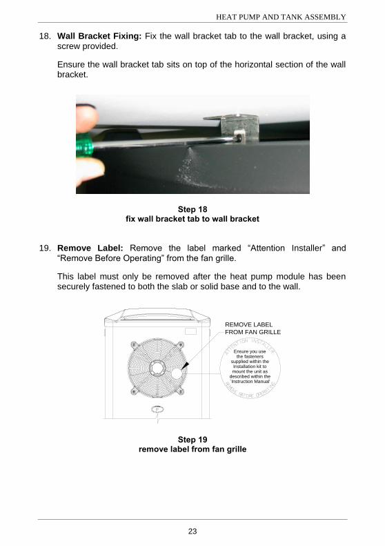
18. Wall Bracket Fixing: Fix the wall bracket tab to the wall bracket, using a screw provided.
Ensure the wall bracket tab sits on top of the horizontal section of the wall bracket.
Step 18 fix wall bracket tab to wall bracket
19. Remove Label: Remove the label marked “Attention Installer” and “Remove Before Operating” from the fan grille.
This label must only be removed after the heat pump module has been securely fastened to both the slab or solid base and to the wall.
Ensure you usethe fasteners
supplied within theInstallation kit tomount the unit as
described within the`Instruction Manual'
REMOVE LABEL
FROM FAN GRILLE
LABEL REMOVAL
REMOTE HEAT PUMP MODULE
Step 19 remove label from fan grille
HEAT PUMP AND TANK ASSEMBLY
24
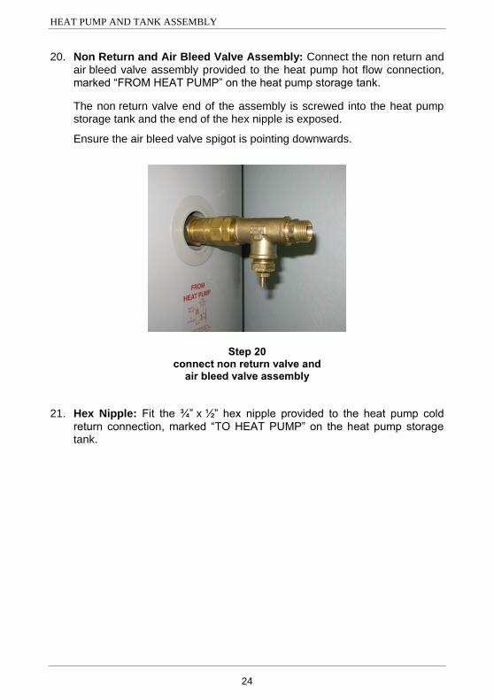
20. Non Return and Air Bleed Valve Assembly: Connect the non return and air bleed valve assembly provided to the heat pump hot flow connection, marked “FROM HEAT PUMP” on the heat pump storage tank.
The non return valve end of the assembly is screwed into the heat pump storage tank and the end of the hex nipple is exposed.
Ensure the air bleed valve spigot is pointing downwards.
Step 20 connect non return valve and
air bleed valve assembly
21. Hex Nipple: Fit the ¾” x ½” hex nipple provided to the heat pump cold return connection, marked “TO HEAT PUMP” on the heat pump storage tank.

HEAT PUMP AND TANK ASSEMBLY
25
22. Heat Pump Circuit: Install the heat pump circuit flow and return pipes between the heat pump module and the heat pump storage tank.
The pipe work between the storage tank and the heat pump module must be fully insulated with closed cell polymer insulation or similar of a minimum thickness of 13 mm. Thicker insulation may be required to comply with the requirements of AS/NZS 3500.4. The insulation must be weatherproof and UV resistant if exposed. The insulation must be fitted up to the connections on both the storage tank and the heat pump module.
All compression fittings must use brass or copper olives.
Either DN15 copper pipe or ½” cross linked polyethylene (PEX) pipe suitably rated for use with a hot water supply and pressures may be used.
Connect one end of the hot water flow pipe to the ½” x ½” hex nipple on the non return and air bleed valve assembly at the heat pump storage tank, using a ½” compression nut and olive provided.
Connect the other end of the hot water flow pipe to the flexible braided hose connection, marked with a red collar, at the heat pump module. A ½” male tube bush is provided for use with copper pipe.
Connect one end of the cold water return pipe to the ¾” x ½” hex nipple at the heat pump cold return connection on the heat pump storage tank, using a ½” compression nut and olive provided.
Connect the other end of the pipe work to the flexible braided hose connection, marked with a blue collar, at the heat pump module. A ½” male tube bush is provided for use with copper pipe.
Attach the insulated pipe work to the wall using pipe clips or saddles.
Slit the 150 mm x 35 mm diameter insulation provided and insulate the non return and air bleed valve assembly, securing with the two cable ties provided.
Ensure the slit of the insulation is on the underside of the assembly and the air bleed valve spigot is accessible.

HEAT PUMP AND TANK ASSEMBLY
26
Step 22
connect insulated heat pump circuit insulate non return valve and pipe work to heat pump module air bleed valve assembly and heat pump storage tank
23. Lower Front Cover: Remove the two screws securing the lower front cover to the storage tank.
Remove the lower front cover from the heat pump storage tank.
Identify the three plugs to connect the three sockets from the heat pump module cable set.
Step 23 remove lower front cover identify three plugs for cable set connection
plugs for cable set
connection

HEAT PUMP AND TANK ASSEMBLY
27
24. Cable Set Connection: Route the cable set from the heat pump module
to the heat pump storage tank.
Unscrew the gland nut from the gland on the cable set and insert the 3 plugs, wires and nut of the cable set through the hole on the right hand side of the electrical connection tab at the bottom of the lower front opening.
It will be necessary to hold the gland nut at an angle to pass it through the hole in the electrical connection tab.
Position the threaded end of the gland in the hole in the electrical connection tab and tighten the nut onto the gland to secure in position.
Connect the 3 plugs (4 pin, 3 pin and 2 pin) from the heat pump storage tank into the 3 sockets from the cable set.
Step 24 secure gland to connect plugs electrical connection tab to sockets
25. Cable Set Conduit: Fix the conduit of the cable set to the wall using saddles, ensuring there is no loose play in the conduit between the heat pump storage tank and the heat pump module.
Alternatively, the conduit may be positioned against either of the insulated heat pump circuit flow and return pipes and secured with the cable ties provided.
Coil up any excess conduit and neatly place behind the heat pump module.

HEAT PUMP AND TANK ASSEMBLY
28
26. Mains Power Connection: Connect the mains power supply wiring to the terminal block and earth connection inside of the lower front cover.
Secure the conduit to the side of the storage tank with a saddle.
Refer to “Connections – Electrical” on page 30 and in the Owner‟s Guide and Installation Instructions supplied with the heat pump storage tank.
Note: The power supply to the water heater must not be switched on until the installation is complete, the water heater is filled with water, air has been purged from the heat pump circuit and a satisfactory megger reading is obtained.
Step 26 connect wiring
27. Lower Front Cover: Refit the lower front cover.
28. Water Connections: Connect the cold water supply and the hot water pipe work to the storage tank.
Connect the temperature pressure relief valve and its drain line.
Refer to “Connections – Plumbing” in the Owner‟s Guide and Installation Instructions supplied with the heat pump storage tank.

HEAT PUMP AND TANK ASSEMBLY
29
29. Water Supply: Turn on the cold water supply and fill the water heater.
Refer to “To Fill And Turn On The Water Heater” on page 32.
It is important the heat pump circuit is purged of air, otherwise the system will not work effectively.
Open all of the hot water taps in the house (don‟t forget the shower).
Connect a 6 mm diameter clear plastic hose to the spigot of the air bleed valve.
Let the other end of the hose go away from the work area where discharge will not cause a nuisance.
Open the air bleed valve, using a 13 mm (½”) spanner.
Air will be purged from the heat pump circuit as the water heater fills with water.
Open the cold water isolation valve fully to the water heater.
Air will be forced out of the taps.
Close the air bleed valve when the air has been purged and water flows freely from the hose.
Remove the hose from the spigot of the air bleed valve.
Close each tap as water flows freely from it.
Check the pipe work, inlet and outlet connections and the connection points for the flexible braided hoses for leaks.
Step 29 connect hose to spigot purge air through air bleed valve
30. Commissioning: Refer to “Commissioning” on page 32 and in the Owner‟s Guide and Installation Instructions supplied with the heat pump storage tank.
30
CONNECTIONS – ELECTRICAL
The power supply to the water heater must not be switched on until the water heater is filled with water and a satisfactory megger reading is obtained.
MEGGER READING
When a megger test is conducted on this water heater, then the following should be noted.
Warning: This water heater contains electronic equipment and 500 V
insulation tests must only be conducted between active and earth and between neutral and earth. An active to neutral test WILL damage the electronics. An insulation test result of between 100 KΩ and 660 KΩ for this water heater is normal. Typically the insulation resistance between live and earthed parts of an electrical installation should not be less than 1 MΩ. However AS/NZS 3000:2000 clause 6.3.3.3.2 „Results‟ states: “The value of 1 MΩ may be reduced to:
0.01 MΩ for sheathed heating elements or appliances; or
a value permitted in the Standard applicable to electrical equipment.”
This model water heater is categorised as a „stationary class 1 motor operated appliance‟ and has been tested to AS/NZS 3350.1:2002 clause 16 „Leakage current and electric strength‟ and has passed the requirements of this Standard. Therefore, this model water heater complies with the condition stated in AS/NZS 3000:2000 clause 6.3.3.3.2 (b).
ELECTRICAL CONNECTION
All electrical work and permanent wiring must be carried out by a qualified person and in accordance with the Wiring Rules AS/NZS 3000 and local authority requirements. This water heater is recommended for connection to a 24 hour per day power supply.

CONNECTIONS – ELECTRICAL
31
WIRING DIAGRAM
Electrical Circuit for Heat Pump – Robertshaw “ST” Thermostat
Rem
ote
LED
Dis
pla
y
CABLIN
G I
N C
ON
DU
IT
INSID
E T
AN
K J
ACKET
CO
NTRO
L
BO
ARD
A
E
N
PO
WER P
LU
G
CO
MPRESSO
R
CAPACIT
OR
FAN
CAPACIT
OR
LO
WER T
AN
K
TH
ERM
ISTO
R (
T0)
CO
MPR
ESSO
R
TH
ERM
ISTO
R (
T2)
EVAPO
RATO
R
TH
ERM
ISTO
R (
T1)
Act
ive L
ow
Voltage
Act
ive R
etu
rn L
ow
Voltage
Neutr
al Low
Voltage
Capaci
tor
Low
Voltage
Eart
h L
ow
Voltage
Therm
isto
r /
LED
Dis
pla
y E
xtr
a L
ow
Voltage
LEG
EN
D
PU
MP P
LU
G
CO
MPRESSO
R P
LU
G
FAN
PLU
G
CO
NTRO
L B
OARD
EN
CLO
SU
RE
REM
OTE
LED
DIS
PLAY
T3 -
Top T
ank T
herm
isto
r
UPPER T
AN
K
TH
ERM
ISTO
R
(T3)
MF
4 1 2 3
SH
IELD
UPPER T
HERM
ISTO
R P
LU
G
CABLE S
ET
BLACK
LO
WER
TH
ERM
ISTO
R
PLU
GTAN
K
PO
WER P
LU
G
TH
ERM
ISTO
R
PLU
G
UPPER
TH
ERM
ISTO
R
PLU
G
Wir
ing
Dia
gra
m -
He
at
Pu
mp
- 5
61
Se
rie
s w
ith
ST
Th
erm
osta
t
BLACK
BRO
WN
BLU
E
BLU
E
BLU
E
BLU
E
BLU
E
BLACK
BLACK
BLACK
BLACK
BLACK
RED
GREEN
/YELLO
W
RED
WH
ITE
RED
GREEN
/YELLO
W
GREEN
/YELLO
W
BLACK
GREEN/YELLOW
BROWN
BLACK
LIGHT RED
BLUE
LIGHT RED
GREEN/YELLOW
RED
BLU
E
BLACK
GREEN
/YELLO
W
GREEN
/YELLO
W
MF
MF
MF
MF
MF
1 3 4 2 1 1 43 4 2 1 2 33 2
T0 -
Bott
om
Tank T
herm
isto
r
T1 -
Evapora
tor
Therm
isto
r
T2 -
Com
pre
ssor
Therm
isto
r
CO
M
NC
NO
CO
MP-A
CO
MP-N
FAN
-NFAN
-A
PU
MP-N
PU
MP-A
NEU
TRAL
EAR
TH
TH
ERM
OSTAT
HEATER
ELEM
EN
T
CO
MPRESSO
R
C
R
PU
MP
FAN
S
32
COMMISSIONING
TO FILL AND TURN ON THE WATER HEATER
The power supply to the water heater must not be switched on until the water heater is filled with water and a satisfactory megger reading is obtained.
Open all of the hot water taps in the house (don‟t forget the shower).
Connect a 6 mm diameter clear plastic hose to the spigot of the air bleed valve, located on the heat pump flow line at the connection to the storage tank.
Let the other end of the hose go away from the work area where discharge will not cause a nuisance.
Open the air bleed valve, using a 13 mm (½”) spanner.
Air will be purged from the heat pump circuit as the water heater fills with water.
Open the cold water isolation valve fully to the water heater.
Air will be forced out of the taps.
Close the air bleed valve when the air has been purged and water flows freely from the hose.
Remove the hose from the spigot of the air bleed valve.
Close each tap as water flows freely from it.
Check the pipe work, inlet and outlet connections and the connection points for the flexible braided hoses for leaks.
Switch on the electrical supply at the isolating switch to the water heater.
Set the timer if one is installed.
The heat pump may take up to one minute to commence operating when the power supply is switched on. The heat pump will only operate when the water in the storage tank requires heating, the heat pump compressor is cool and power is available at the water heater. Once the heat pump is operating, the system may switch to the booster heating unit, after three minutes of operation, instead of the heat pump if it detects the ambient air temperature is outside the heat pump‟s operating range of between
a minimum of 3°C to 5 C and maximum of 45 C to 55°C.

COMMISSIONING
33
Note: The heat pump may not turn on after having just completed a heating cycle and more hot water is drawn from the water heater. The heat pump will wait until the compressor has cooled down and the conditions for start up are favourable, in order to protect the compressor from damage. This may take up to 90 minutes from the last heating cycle. It is important to wait for five minutes after the heat pump has activated to ensure it continues to operate and is functioning correctly. Explain to the householder or a responsible officer the functions and operation of the heat pump water heater. Upon completion of the installation and commissioning of the water heating system, leave this guide with the householder or a responsible officer.
TO TURN OFF THE WATER HEATER
We recommend you leave the water heater switched on in the event of freezing conditions occurring (refer to “Freeze Protection” on page 6). If it is necessary to turn off the water heater on completion of the installation, such as on a building site or where the premises are vacant, then:
Switch off the electrical supply at the isolating switch to the water heater.
Close the cold water isolation valve at the inlet to the water heater.
Notes: The freeze protection system will be rendered inoperable if electrical power is not available at the water heater. Damage caused by freezing due to the unavailability of power at the water heater is not covered by warranty (refer to “Warranty Exclusions” on page 39). If the power has been switched off to the water heater and there is a risk of freezing, then it is necessary to drain the water heater (refer to the “Draining The Water Heater” section in the Owner‟s Guide and Installation Instructions supplied with the heat pump storage tank).

COMMISSIONING
34
DIAGNOSTIC FEATURES OF THE HEAT PUMP CONTROLLER
An operating mode monitor is located on the front of the heat pump module and houses a green and a red LED. The green LED, marked “NORMAL”, indicates the current operating mode of the heat pump water heater and the red LED, marked “ATTENTION”, indicates a fault mode. The green LED will emit either a constant glow or a series of flashes, with a 2 second interval between each series. A series of long green flashes may also be emitted. The red LED will emit a series of flashes, with a 2 second interval between each series, only if there is a particular fault condition within the system. The Operating Modes are:
Flashes Operating Modes
solid green (remains on)
Standby mode – water is hot
1 x green Call for heating received – system checks performed Note: unit may wait and continue flashing until compressor has cooled from its last operation
2 x green Circulator commences circulation
3 x green Heat pump operation – compressor and fan running
4 x green Defrost mode – circulator operates for three (3) minutes
long green Heating unit on – ambient air temperature below 3°C to 5°C or above 45°C to 55°C
no green (remains off)
No power at the water heater or a possible fault condition
Refer to notes below before calling for service
Flashes Fault Modes
1 x red Heating unit on compressor over temperature (possible circulator fault)
2 x red Heating unit on compressor fault condition
3 x red Heating unit on compressor cooling fault condition
4 x red Heating unit on lower tank thermistor fault condition
5 x red Heating unit on evaporator thermistor fault condition
6 x red Heating unit on compressor thermistor fault condition
7 x red Heating unit on upper tank thermistor fault condition

COMMISSIONING
35
Notes:
Power must be available at the water heater and to the heat pump for the LEDs to glow or flash.
Time controlled power supply
If the water heater is connected to a time controlled power supply, then during periods of no power supply at the water heater the LEDs will be off.
This is not a fault condition, but a result of no power being available to energise the LEDs.
The green LED will recommence glowing or flashing when power is available again at the water heater.
If there is power to the water heater and the green LED is off or the red LED is flashing, this indicates there may be a fault condition with the water heater. The red LED may emit up to seven flashes in each series of flashes. Refer to “Possible fault condition” on page 35.
Possible fault condition
There may be a fault condition with the water heater if either:
there is power available at the water heater and the green LED is off
Before phoning to arrange a service inspection due to the green LED being off, refer to “Heat Pump Is Not Operating” in the “Save A Service Call” section of the Owner‟s Guide and Installation Instructions supplied with the heat pump storage tank.
or
the red LED is flashing – the red LED may emit up to seven flashes in each series of flashes
The fault condition which led to the red LED flashing may be cleared after the backup heating cycle by the booster heating unit has completed and the red LED has gone out. If the red LED has gone out, when heating is next required, the green LED will flash and the heat pump will commence to operate. If the heat pump stops operating and the red LED recommences to flash, a service call may be required.
Before phoning to arrange a service inspection due to the red LED flashing, refer to “Heat Pump Is Not Operating” in the “Save A Service Call” section of the Owner‟s Guide and Installation Instructions supplied with the heat pump storage tank.

36
WATER SUPPLIES
This water heater must be installed in accordance with this advice to be covered by the warranty. This water heater is manufactured to suit the water conditions of most public reticulated water supplies. However, there are some known water chemistries which can have detrimental effects on the water heater and its operation and / or life expectancy. If you are unsure of your water chemistry, you may be able to obtain information from your local water supply authority. This water heater should only be connected to a water supply which complies with these guidelines for the water heater warranty to apply.
CHANGE OF WATER SUPPLY
The changing or alternating from one water supply to another can have a detrimental effect on the operation and / or life expectation of a number of components in this water heater. Where there is a changeover from one water supply to another, e.g. a rainwater tank supply, bore water supply, desalinated water supply, public reticulated water supply or water brought in from another supply, then water chemistry information should be sought from the supplier or it should be tested to ensure the water supply meets the requirements given in these guidelines for warranty to apply.
SATURATION INDEX
The saturation index (SI) is used as a measure of the water‟s corrosive or scaling properties. Where the saturation index is less than –1.0, the water is very corrosive and warranty does not apply to the water heater. In a corrosive water supply, the water can attack copper parts and cause them to fail. Where the saturation index exceeds +0.40, the water is very scaling and warranty does not apply to the water heater. Water which is scaling may be treated with a water softening device to reduce the saturation index of the water.

WATER SUPPLIES
37
CHLORIDE AND PH
Where the chloride level exceeds 250 mg/L warranty does not apply to the water heater. In a high chloride water supply, the water can corrode stainless steel parts and cause them to fail. Where the pH is less than 6.0 warranty does not apply to the water heater. pH is a measure of whether the water is alkaline or acid. In an acidic water supply, the water can attack stainless steel parts and cause them to fail. Water with a pH less than 6.0 may be treated to raise the pH. The water supply from a rainwater tank in a metropolitan area is likely to be corrosive due to the dissolution of atmospheric contaminants.
SUMMARY OF WATER CHEMISTRY ADVICE AFFECTING WARRANTY
The warranty of and the water heater, including this heat pump module, does not apply if the water heater is connected at any time to a water supply with water chemistry of:
Water Chemistry
Saturation Index (SI) < -1.0
Saturation Index (SI) > +0.4
Chloride > 250 mg/L
pH < 6.0
Refer to “Water Supplies” in the Owner‟s Guide and Installation Instructions supplied with the storage tank for the complete water supply statement.

38
This page is intentionally blank.
39
WARRANTY NOTE
The heat pump water heater is covered by a comprehensive warranty. For full warranty details, refer to the Owner‟s Guide and Installation Instructions supplied with the storage tank. The part extracts from the Warranty Condition (5) and warranty exclusions (c), (d), (e), (f) and 2 of the water heater warranty should be noted before commencing the installation. The term “water heater” used in the Warranty, Warranty Conditions and Warranty Exclusions means the Manufacturer supplied storage tank, heat pump module and components.
WARRANTY CONDITIONS
5. Where the water heater is installed in a position that does not allow safe, ready access, the cost of accessing the site safely, including the cost of additional materials handling and / or safety equipment, shall be the owner’s responsibility.
WARRANTY EXCLUSIONS
c) Where the water heater or water heater component has failed directly or indirectly as a result of: excessive water pressure; excessive temperature and / or thermal input; blocked overflow / vent drain; corrosive atmosphere; ice formation in the pipe work to or from the water heater.
d) Where the water heater or water heater component has failed directly or indirectly as a result of ice formation in the waterways of: a heat pump water heater system where the system has not been installed in accordance with the water heater installation instructions; a heat pump water heater with a freeze protection system where the electricity supply has been switched off or has failed.
e) Where the water heater is located in a position that does not comply with the water heater installation instructions or relevant statutory requirements, causing the need for major dismantling or removal of cupboards, doors or walls, or use of special equipment to bring the water heater to floor or ground level or to a serviceable position.
f) Where the water heater has been connected at any time to a water supply that does not comply with the water supply guidelines as outlined in the Owner’s Guide and Installation Instructions.
2. SUBJECT TO ANY STATUTORY PROVISIONS TO THE CONTRARY, THIS WARRANTY
EXCLUDES ANY AND ALL CLAIMS FOR DAMAGE TO FURNITURE, CARPETS, WALLS, FOUNDATIONS OR ANY OTHER CONSEQUENTIAL LOSS EITHER DIRECTLY OR INDIRECTLY DUE TO LEAKAGE FROM THE WATER HEATER, OR DUE TO LEAKAGE FROM FITTINGS AND / OR PIPE WORK OF METAL, PLASTIC OR OTHER MATERIALS CAUSED BY WATER TEMPERATURE, WORKMANSHIP OR OTHER MODES OF FAILURE.
Revision Date: 2009 November 126574C
40