installation instructions and maintenance manual side to
TRANSCRIPT
Installation Instructions and Maintenance Manual
Side to Side Monitor (SSM) Arm

Preface
IMPORTANT, PLEASE READ CAREFULLY
Thank you for your purchase with Amico Accessories Inc.
This unit is designed for long lasting performance, providing the end user complies with assembly and maintenance procedures. This Instruction Manual is your guide to ensure that you get the best performance out of the equipment. Amico Accessories is not responsible for any damage as a result of (but not limited to) abuse and other problems that may be a direct or indirect result of failure to comply with the instructions provided in this manual.
Please note these key words and symbols:
WARNING Steps where extra care should be taken to prevent injuries and damage.
NOTE Steps that point out helpful information.
Medical Facility Responsibilities
Preventive maintenance checks must be performed regularly to maintain the quality and performance of this product. Any parts that may be broken, missing, worn, distorted, or contaminated in any way should not be used and all affected parts should be replaced immediately. Should the necessity of any repair be suspected; please contact your local distributor or call 1-877-264-2697.

Table of Contents
Section 1: Installation Preparation 4-6Installation Tools Requirements 4Pre-Installation Information 5Typical Installation Reference for SSM 6
Section 2: Installation on Rail Systems 7-10Mounting to MRS (Monitor Rail System) 7Mounting to Hill-Rom Vertical Rail (with the G-Track Adapter (GTA)) 8Mounting to the VRS (Vertical Rail System) with the V-Adapter 9Mounting to the Ergotron and Rubbermaid Rail 10OSHPD Anchor Pre-Approval OPA-1743 10
Section 3: Monitor Installation 11-17Monitor Mounting 11Monitor Shelf: 3" (76.2 mm) Top/Back Mount, 5" (127 mm) Top/ Back Mount and VESA 12Monitor Shelf: 6" (152.4 mm) Drop On 13Monitor Shelf: Philips Intellivue 14Monitor Shelf: Welch Allyn 15Monitor Mounting: VESA 75/100 16Accessory Shelf: Disc 17
Section 4: Adjustments 18-25Rotation (SSM Side To Side) 18Adjusting the Tension Bolt 19Monitor Tilt 20-21Rotation (Monitor Head) 22Portrait and Landscape Adjustment 22Portrait and Landscape Limiter 23Cable Management: SSM Cable Management 24Cable Management: MRS Rail Cover 25
Section 5: Troubleshooting, Maintenance and Product Classification 25-30Cleaning 25Troubleshooting 26Preventive Maintenance (SSM Monitor Arm) 27-28Part Number Matrix 29-30Warranty Information 31

4 Amico Accessories Inc.
Section 1: Installation Preparation
Installation Tools Requirements
The following table lists all the tools and parts required for installation
NOTE: Amico does not provide any display hardware, nor the tools necessary for assembly (All above in grey text).
NOTE: Tools and the monitor-dependant hardware set are not provided by Amico Accessories Inc.
A B
1
2
3
4
Item Item number Quantity
Phillips screw driver #2 A1 1
Hex keys (1/8" [0.3 cm], 3/16" [0.5 cm], M3, M4) A2 1 each
Socket wrenches (12 mm [1.2 cm],1/2" [0.05 cm]) A3 1 each
Adjustable wrench A4 1
SSM arm B1 1
Mounting adapter/plate (many options)and Monitor dependant hardware set
B2 1
Mounting shelf (0-9, W) B3 1
Extension arm (optional) B4 1

www.amico.com 5
Section 1: Installation Preparation
Pre-Installation Information (Please read carefully before starting)
WARNING: VERIFY THAT RAILS HAVE BEEN INSTALLED IN ACCORDANCE WITH AMICO RAIL INSTALLATION INSTRUCTIONS. RAIL FAILURE WITH DEVICES MOUNTED CAN CAUSE SERIOUS INJURY AND EQUIPMENT DAMAGE.
WARNING: IT IS DANGEROUS TO USE THE ARM FOR WEIGHTS OUTSIDE OF THE RATED RANGE. STRUCTURAL FAILURE AND/OR SERIOUS INJURY COULD RESULT.
WARNING: DO NOT POSITION THE SSM MONITOR ARM ABOVE A PATIENT.
WARNING: IT SHALL BE THE RESPONSIBILITY OF THE HOSPITAL, ITS CONSULTANTS AND/OR CONTRACTORS TO DETERMINE IF THE WALL IS ADEQUATE TO SAFELY MOUNT THE SPECIFIC INSTRUMENT. THIS INCLUDES THE SELECTION OF APPROPRIATE FASTENERS AND THE PROPER INSTALLATION OF EQUIPMENT, REGARDLESS OF WHAT IS SUPPLIED WITH YOUR SSM MONITOR ARM. SEE RAIL INSTRUCTIONS FOR SPECIFIC WALL CHANNEL GUIDELINE INFORMATION.
WARNING: VERIFY THE WEIGHT OF THE DEVICE TO BE MOUNTED. SINGLE ARM SSM MONITOR ARMS ARE RATED FOR 30 LBS (13.6 KG), DUAL ARM SSM MONITOR ARMS ARE RATED FOR 15 LBS (6.8 KG). PLEASE REFER TO WEIGHT RATING LABEL, LOCATED EITHER ON THE TOP OR BOTTOM OF THE ARM ASSEMBLY, DEPENDING ON THE MODEL. CHECK THAT THE DEVICE TO BE MOUNTED DOES NOT EXCEED THE WEIGHT RATING. SERIOUS INJURY AND DAMAGE TO THE ARM CAN OCCUR AS A RESULT OF OVERLOADING THE ARM ASSEMBLY.
For installation on non-Amico rails, ensure the rail is safe for the application.
If you are unsure about any part of the installation process or product use, please contact an Amico Accessories product Specialist: 1-877-264-2697
Considerable efforts have been made to ensure the safety of your hospital staff and your patients. The installation itself is beyond the control of Amico Accessories. Accordingly, Amico Accessories will not be responsible for failure related to the installation of the product.
HAVE A PRODUCT QUESTION? GIVE US A CALL AT: 1-877-264-2697

6 Amico Accessories Inc.
Typical Installation Reference for SSM
The diagram below illustrates the components referenced in relation to one another in the installation of the SSM Monitor Arm. Please follow the instructions outlined herein to ensure proper installation.
SSM MONITOR ARM
1. Monitor Mounting Adapter VESA LCD mount shown, other options available
2. Monitor Head - Rotation Monitor rotation adjustment
3. SSM Joint Rotates the monitor head to the desired position
4. MRS Adapter Adapter for the MRS rail
5. Cable Management Manages the cables of the monitor for better organization
Section 1: Installation Preparation
SSM MONITOR ARM
1. Monitor Mounting Adapter (Pg.12-18)VESA LCD mount shown, other options available
2. Monitor Head - Rotation (Pg. 22)Monitor Rotation Adjustment3. SSM Joint (Pg. 20)Rotates the Monitor Head to the desired position4. Mounting Adapter (Pg. 6-9)MON adapter shown for MRS rail
5. MRS Adapter (Pg. 9)Adapter for the MRS Rail
6. Cable Management (Pg. 25)Manages the cables of the Monitor for better organization.
1
2
3
4
5
6
12
3
4
5
6

www.amico.com 7
Section 2: Installation on Rail Systems
WARNING: DO NOT ATTEMPT TO MOUNT/REMOVE THE ARM FROM THE RAIL WHEN LOADED WITH ANY INSTRUMENT
Mounting to the MRS (Monitor Rail System)
WARNING: SUPPORT SSM ARM UNTIL THE SET SCREWS ARE TIGHTENED, SSM ARM CAN SLIDE DOWN WHEN SET SCREWS ARE NOT TIGHTENED.
NOTE: Top and bottom stoppers prevent the adapter from sliding out of the MRS. To remove, the adapter must be removed from the top with the top stopper pressed into the rail (Figure 2).
NOTE: To slide the arm vertically in the channel, lift the arm near the monitor and push up or down at the adapter (Figure 1).
1. Support the bottom of the arm with one hand, guide the adapter into the top of the channel (Figure 1).
2. Once the arm is at the desired height, tighten the two set screws located at the bottom of the adapter using a 1/8" (3 mm) HEX key. DO NOT release the SSM Monitor Arm until the two set screws are tight. The SSM Monitor Arm may slide down the rail if the set screws are not tightened.
Figure 2
Bottom Stopper
Top Stopper
MRS Rail: Length for representational use only
Figure 1
1/8" (3 mm)set screws
SSM Arm
Standard MON Channel Adapter
MRS Rail

8 Amico Accessories Inc.
Section 2: Installation on Rail Systems
Mounting to Hill-Rom Vertical Rail (with the G-Track Adapter (GTA))
WARNING: TO PREVENT THE ADAPTER FROM FALLING DOWN THE CHANNEL, ENSURE THAT THE SCREWS ARE FASTENED AS TIGHT AS POSSIBLE. AFTER INSTALLATION, ROTATE THE SSM ARM SIDE TO SIDE AND VERIFY NO MOVEMENT IS PRESENT BETWEEN THE ADAPTER AND THE RAIL.
WARNING: REMOVAL OF LOCK NUTS WILL REQUIRE A NEW SET FOR REINSTALLATION. PLEASE CONTACT AMICO ACCESSORIES FOR SPARE PARTS, 1-877-264-2697.
NOTE: Before installing, ensure two regular nuts and two lock nuts are loosened to the tip of the G-adapter screws. This will allow the head of the G-adapter screws to adjust into the profile of the Hill-Rom rail (Figure 3).
1. Support the bottom of the SSM Arm and guide the head of the top screw into the opening of the rail (Figure 1 and 2).
2. Ensure the flange on the GTA is properly aligned with the rail. Slide the GTA up so that the head of the bottom screw slides into the opening of the rail (Figure 3).
3. Position the SSM Arm at the desired height. Tighten the two regular nuts and then the two lock nuts on the top and bottom of the adapter using a 12 mm socket wrench.
4. Cover the nuts with the two plastic caps provided (Figure 4).
Figure 1
Hill-RomRail
Front
Opening of the rail
Jam nut, lock nut, and
plastic cap
Figure 3
Side of the G-Adapter
12 mm nuts, lock nuts
Flange
Backside
Head of the top GTA pin
Head of the bottom GTA pin
Figure 2
G-adapter Screw
Figure 4
Plastic caps

www.amico.com 9
Section 2: Installation on Rail Systems
Mounting to the VRS (Vertical Rail System) with the V-Adapter
WARNING: TO PREVENT THE V-ADAPTER FROM FALLING DOWN THE CHANNEL, ENSURE THAT THE SCREWS ARE FASTENED AS TIGHT AS POSSIBLE. ROTATE SSM ARM SIDE TO SIDE AFTER INSTALLATION TO VERIFY NO MOVEMENT IS PRESENT BETWEEN THE ADAPTER AND THE RAIL.
NOTE: Before installation, ensure two nuts and two knobs are loose to the tip of the V-adapter screws. This will allow the head of the V-adapter screws to adjust into the profiles of the vertical rail.
1. Angle the SSM Arm from either side and guide the heads of the top and bottom screws into the channel of the rail (Figure 1-3)
2. Ensure the flange on the adapter is properly aligned with the rail.
3. Position the arm to the desired height and fasten two knobs and two nuts (12 mm) to the tightest possible position. Cover the nuts with the two plastic caps provided (Figure 4).
Figure 1 Figure 4
Vertical Rail
End Cap
Screw Knobs
Tighten thumb screws and nuts
Flange
Backside
Head of the top screw
Head of the bottom screw
Figure 2
V-adapter Screw
Figure 3
Side of theV-adapter
Side ofthe VRS

10 Amico Accessories Inc.
Section 2: Installation on Rail Systems
OSHPD Anchor Pre-Approval OPA-1743
Mounting to the Ergotron and Rubbermaid Rail (15 lbs [6.8 kg] max. weight capacity)
WARNING: TO PREVENT THE SSM ARM FROM FALLING DOWN THE CHANNEL, ENSURE THAT THE TWO NUTS ARE FASTENED AS TIGHT AS POSSIBLE.
NOTE: COW-adapter will work both with Ergotron and Rubbermaid rails. Set the slider horizontally to insert theadapter to the Rubbermaid rail, and set the slider vertically to insert the adapter to the Ergotron rail (Figure 1:Rubbermaid) (Figure 2: Ergotron).
NOTE: Before installing, ensure two nuts are loosened to the tip of the screws. This will allow the sliders to adjust into the profile of the rail.
1. Remove the cap from the top of the rail.
2. Ensure the sliders are vertical for the Ergotron or horizontal for the Rubbermaid rail.
3. Align the sliders with the slot on the rail and slide the adapter into the slot from the top of the rail (Figure 4 and 5).
4. Position the adapter to the desired height and tighten the nuts. Replace plastic caps on to the nuts.
Figure 1 Figure 2 Figure 3
Sliders set horizontally for the
Rubbermaid rail
Sliders set vertically for the
Ergotron rail
Figure 4 Figure 5
Top of theErgotron
Ergotron rail shown
COW - Rail
SlotCOW - Rail
Slot
Plastic caps
COW - Rail
In compliance with standards established for the anchor and installation of instrument support systems by the California Office of Statewide Health Planning and Development (OSHPD), Amico Accessories Inc. has obtained preapproval for MRS 19" (482.6 mm) Wall Channels or longer with extension Arm. For proper installation requirements please refer to our OPA document.

www.amico.com 11
Section 3: Monitor Installation
Monitor Mounting
WARNING: ENSURE THAT THE ARM IS IN THE HIGHEST POSITION AND IS LOCKED BEFORE MOUNTING OR REMOVING THE ARM FROM THE CHANNEL.
WARNING: ENSURE THE MONITOR SHELVES/PLATES PROVIDED BY AMICO ACCESSORIES INC. OR OTHER MANUFACTURERS ARE ASSEMBLED AS DIRECTED AND MATCH THE SHELF REQUIREMENT. IF A MONITOR SHELF/PLATE DOES NOT MATCH THE REQUIREMENT, PLEASE CONTACT AMICO ACCESSORIES INC. AT 1-877-264-2697
NOTE: Amico Accessories Inc. carries a variety of Mounting Shelves and adapters that attach to the SSM Arm. View the SSM Matrix on pages 29 and 30 for more information.
NOTE: SSM - XXY - (C) – (Z) - Variables X, Y, C and Z are placeholders for part classification. Please refer to the SSM Matrix on pages 29 and 30 for more information.

12 Amico Accessories Inc.
Section 3: Monitor Installation
Monitor Shelf: 3" (76.2 mm) Top/Back Mount, 5" (127 mm) Top/ Back Mount and VESA
WARNING: ENSURE THE MOUNTING SHELF IS SECURELY LOCKED AND HORIZONTAL TO PREVENT THE MONITOR FROM SLIDING AND FALLING (SEE PAGE 20).
WARNING: ON THE BOTTOM OF THE MOUNTING SHELF THERE IS A PLUNGER THAT SECURES THE SHELF TO THE MOUNTING ADAPTER. SIMPLY PULL DOWN ON THE PLUNGER, ALIGN THE ADAPTER PLATE WITH THE SHELF AND RELEASE THE PLUNGER ONCE POSITIONED OVER THE CLEARANCE HOLE (FIGURE 3).
NOTE: The plunger can be locked in the open position by pulling and twisting it.
1. First install the mounting adapter to the device (Please refer to the adapter installation manual provided with the adapter) (Figure 1 on previous page).
2. Loosen the plastic screws on the bottom side of the mounting shelf. Pull down on the plunger lock at the bottom of the mounting shelf and twist it to keep it open. Slide the adapter laterally onto the mounting shelf until the plunger aligns with the clearance hole at the front of the mounting adapter (Figure 3).
3. Release the plunger and tighten the plastic screws by hand (Figure 4).
Mounting shelf
Monitor
Mounting adapter
Front of the mounting
adapter
Monitor dependant hardware
Figure 1 Figure 2
Mounting shelf
Front of the shelf
Plunger Lock
5" (127 mm) mounting shelf is shown above
Plastic Screws
Plunger released
Plunger pulled
Figure 3 Figure 4

www.amico.com 13
Section 3: Monitor Installation
Monitor Shelf: 6" (152.4 mm) Drop On
WARNING: Ensure the mounting shelf is secure and vertical to prevent the monitor from sliding and/or falling.
NOTE: Quick installation system: On the back of the mounting plate there is a plunger that secures the plate to the mounting adapter. Simply slide and align the adapter to the shelf and the plunger will automatically engage and lock.
1. First, install the mounting adapter to the back of the monitor (Please refer to the adapter installation manual provided with the adapter).
2. Lift the monitor and slide the mounting adapter plate on to the mounting shelf. Slide the monitor down until the mounting hole on the mounting adapter aligns with the plunger (Figure 1). When the hole and the plunger are perfectly aligned the plunger will automatically lock. If the plunger does not lock automatically then lock the plunger manually by turning it. Tighten the locking screws by hand to the tightest possible position (Figure 2).
Figure 1 Figure 2
Mounting shelf
Plunger Lock
Locking screws
Mounting adapter plate
Mounting hole

14 Amico Accessories Inc.
Section 3: Monitor Installation
Monitor Shelf: Philips Intellivue
WARNING: ENSURE THE MOUNTING SHELF IS FIRMLY LOCKED AND HORIZONTAL TO PREVENT THE MONITOR FROM SLIDING AND FALLING.
NOTE: Philips recommends a Maximum tilt of 15°.
NOTE: It is recommend to use M6 x 20 mm screws with thread locker or patched screws in order to eliminate possible dangers.
1. Attach the table top mount from Philips (not supplied by Amico) to the mounting shelf by securing the 3 screws through the shelf (Figure 2).
2. Place the monitor to the table top mount until it clicks (Figure 3).
3. Tilt the monitor to the desired angle and re-adjust the tension as needed with a 12 mm wrench (Figure 4).
Philips Table Top Mount(not supplied)
12 mm hex nut
To tighten
To loosen
Three 20 mm M6 screws
Table top mount
Mounting shelf
Figure 1 Figure 2 Figure 3 Figure 4

www.amico.com 15
Section 3: Monitor Installation
Monitor Shelf: Welch Allyn
WARNING: ENSURE THE MOUNTING SHELF IS SECURE AND HORIZONTAL TO PREVENT THE MONITOR FROM SLIDING AND FALLING.
1. To attach the monitor to the Welch Allyn shelf, lift the monitor to match the front lip of the mounting plate. Slide the monitor laterally until the mounting hole on the monitor aligns with the thumb screw on the adapter (Figure 1).
2. Tighten the thumb screw to the tightest possible position (Figure 2).
Figure 1 Figure 2
Thumb screw
Front lip
Thumb screw

16 Amico Accessories Inc.
Section 3: Monitor Installation
Monitor Mounting: VESA 75/100
NOTE: Setting the VESA shelf horizontally can make the mounting procedure easier.
NOTE: If the original monitor bolts are too large, determine the screw size and consult with Amico Accessories Inc.
1. Determine the monitor mounting configuration. VESA 75 (75 mm x 75 mm with M4 threads) or VESA 100 (100 mm x 100 mm with M4 threads).
2. If a VESA 75 configuration is present on the monitor then lift the monitor to match the mounting holes on the VESA 75 shelf (Figure 1). Fasten two M4 screws by hand through the back of the VESA 75 shelf and into the rear of the monitor. Secure the two remaining screws through the holes on the back of the VESA 75 shelf and into the monitor. Ensure all screws are secured. Be sure not to force the screw in, as it may strip the head. The VESA 100 adapter will not be required. Tighten using a cross pattern.
3. If a VESA 100 configuration is present on the monitor then attach the back of the VESA 100 adapter to the front of the VESA 75 shelf. This is done by inserting four M4 screws through the holes on the back of the VESA 75 shelf, into the inner threads from the back of the VESA 100 adapter (Figure 2 and 3) Lift the monitor to match the mounting holes on the VESA 100 adapter. Secure four M4 screws provided by the monitor manufacturer through the back of the VESA 100 adapter and into the monitor. Ensure all screws are secured; be sure not to force the screw in, as it may strip the head. Tighten using a cross pattern.
Figure 1 Figure 2 Figure 3
M4 screws for VESA
Front of the VESA 100 adapter
M4 inner threads
M4 mounting hole
Screws
VESA 75
VESA 100
Side of the VESA 75 and VESA 100 together
M4 mounting hole
Front of the VESA 75 shelf

www.amico.com 17
Section 3: Monitor Installation
Accessory Shelf: Disc
NOTE: It is possible to attach accessories to the top or bottom side of the SSM Arm using this same mount (Figure 1).
NOTE: Amico Accessories Inc. carries a variety of different accessories that attach to the head of the SSM Arm.
Figure 1
Figure 5
Figure 2
Figure 6
Figure 3
Figure 7
Figure 4
Figure 8
6" and 12" post(152.4 mm and 304.8 mm)
Single or dual cord holder
Keyboard handle
Screw type: 10 x 32
Top side Bottom side
(Disc installed on the top and Disc installed on the bottom)
Dual Head Keyboard Tray Laptop Holder ARS Rail

18 Amico Accessories Inc.
Rotation (SSM Side To Side)
WARNING: BOTH ARMS HAVE A 180° ROTATION. ENSURE PROPER CLEARANCE AROUND THE ARM(S) TO AVOID COLLISION.
NOTE: If the arm becomes difficult to rotate, or too loose, please contact Amico Accessories Inc.: 1-877- 264-2697.
Single Arm Rotation:To rotate the arm, simply push on the side of the arm or the mounted monitor in the direction desired (Figure 1).
Dual Arm Rotation:To rotate at the end point (near wall), push on the side of the extension arm, near the mid-way point (Figure 2). To rotate at the midway point, hold the extension arm with one hand and push on the side of the SSM Arm with the mounted monitor in the direction desired (Figure 3).
Section 4: Adjustments
Figure 5
1 23
4
DETAIL 1 SCALE 1 : 5
DETAIL 2 SCALE 1 : 5
DETAIL 3 SCALE 1 : 5
DETAIL 4 SCALE 1 : 5
Detail 1Scale 1:5
Detail 2Scale 1:5
Detail 3Scale 1:5
Detail 4Scale 1:5
Figure 4
Arm rotated
Figure 1
To rotate at first arm
First arm rotated
Figure 2
Second arm rotated
To rotate at second arm
Figure 3
End point
End point
Midway point

www.amico.com 19
Adjusting the Tension Bolt
WARNING: It is not recommended to adjust the rotation tension bolt. If you do, be sure not to unfasten the bolt too much or the head will disassemble from the arm.
WARNING: Be sure not to adjust rotation tension bolt at the bottom end of the arm. This may damage the hardware inside the head.
1. The rotation tension bolt is located under the front-end of the arm. This is where the tension of the heads rotation is adjusted (Figure 1).
2. The mounted device rotates at the front of the arm. To rotate the device, push the corners of the device or the head (Figure 2 and 3).
Section 4: Adjustments
1/2" (12.7 mm) bolt
Rotation Tension Point
Figure 1 Figure 2 Figure 3
Head Rotated SSM Head without Rotation

20 Amico Accessories Inc.
Section 4: Adjustments
Monitor Tilt
WARNING: ALWAYS SUPPORT THE MONITOR IF ADJUSTING THE TILT ANGLE WHILE A MONITOR IS MOUNTED.
WARNING: FOR HEAVIER MONITORS, IT IS STRONGLY RECOMMENDED TO CHECK WHETHER THE TILT-SETTING LEVER IS TIGHTENED TO THE TIGHTEST POSITION WHILE THE MONITOR IS ATTACHED. IF THE ADJUSTMENT LEVER CANNOT BE TIGHTENED ENOUGH TO SECURE THE MONITOR IN PLACE, PROCEED TO STEP 3.
WARNING: DO NOT ADJUST TILT-ANGLE WITHOUT FIRST LOOSENING THE TILT-SETTING LEVER.
NOTE: Tilt-angle setting is ONLY ACHIEVED BY TIGHTENING THE TILT-SETTING LEVER. DO NOT tighten nuts adjacent to the Tilt-setting Lever.
Tilt Hinge Tilt-Setting Lever
4 mm (5/32") Allen NutPatient Monitor
Shelf
1. To TIGHTEN the Tilt-Hinge (in order to set the desired tilt angle), TURN the Tilt-Setting Lever CLOCKWISE. [Turning the Lever COUNTER-CLOCKWISE will ENABLE tilt movement]
4 mm Allen Key 12 mm Socket Wrench
Tools Reference
Tighten Loosen

www.amico.com 21
Section 4: Adjustments
2. A sufficient level of tightness may not be achieved by the time the Tilt-setting Lever touches the back of the Patient Monitor Shelf (Figure 1). If this occurs, PULL the lever AWAY from the MON Head to disengage the lever (Figure 2). TURN the lever COUNTER-CLOCKWISE (Figure 3 [1]) to create space for the lever to further tighten. PUSH the lever TOWARDS the MON Head (Figure 3 [2]) to re-engage the lever. Repeat Step 1 to further tighten the Tilt Hinge.
3. If a sufficient level of tightness cannot be achieved, use a 4 mm Allen key to loosen the screw that keeps the Tilt-setting Lever in place (Figure 4). Remove the screw and spring (Figure 5). Remove the lever to reveal the 12 mm hex-nut (Figure 6).
NOTE: In some instances (especially with heavy monitors), a sufficient level of tightness cannot be achieved. If monitor tilt-angle will not set, proceed to Step 3.
4. Turn the 12 mm hex-nut CLOCKWISE using the 12 mm socket wrench (Figure 7) to tighten.
5. Test to confirm the tilt-angle is secure.
Figure 1Lever blocked by Patient Monitor Shelf
Figure 2Pull lever AWAY from the MON Head
Figure 3Rotate Lever COUNTER-CLOCKWISE [1] and PUSH [2]
Figure 4 Figure 5 Figure 6
Figure 7
Spring
1
2

22 Amico Accessories Inc.
Section 4: Adjustments
Rotation (Monitor Head)
WARNING: DO NOT ADJUST THE ROTATION TENSION BOLT. IF THERE ARE PROBLEMS ASSOCIATED WITH THE HEAD ROTATION PLEASE CONTACT AMICO ACCESSORIES INC. OR REFER TO THE TROUBLESHOOTING SECTION (PAGE 28) FOR MORE INFORMATION.
1. The monitor rotates at the front of the arm. To rotate the monitor, push the corners of the device or the head while holding the SSM Arm. If the SSM is not held in place, the monitor head will rotate with the swivel post (Figure 1).
Portrait and Landscape Adjustment
NOTE: It is recommended to make the adjustments with the monitor mounted.
1. To adjust the orientation, turn the monitor. The monitor can turn up to 135° in either left or right. The stopper is built so that it cannot rotate further than 135° (Figure 2).
2. To adjust the tension of the portrait and landscape feature for VESA 75 plate, The monitor must be removed from the Monitor Head. Remove the four VESA 75 screws from the monitor. Turn the Rotational Tension Bolt (Figure 2) in the center of the VESA adapter clockwise to tighten the tension. Turn counterclockwise to loosen the tension. After tension is adjusted, remount the monitor (Refer to Page 16).
3. To adjust the tension of the portrait and landscape feature for VESA 100 plate, The monitor must be removed from the Monitor Head. Remove the four inner screws that secure the VESA 100 plate to the VESA 75 plate. There is no need to remove the VESA 100 plate from the monitor. Turn the Rotational Tension Bolt (Figure 2) in the center of the VESA adapter clockwise to tighten the tension. Turn counterclockwise to loosen the tension. After tension is adjusted, remount the monitor (Refer to Page 16).
Figure 1
Figure 2
Head Rotated
Rotational Tension Bolt
www.amico.com 23
Portrait and Landscape Limiter
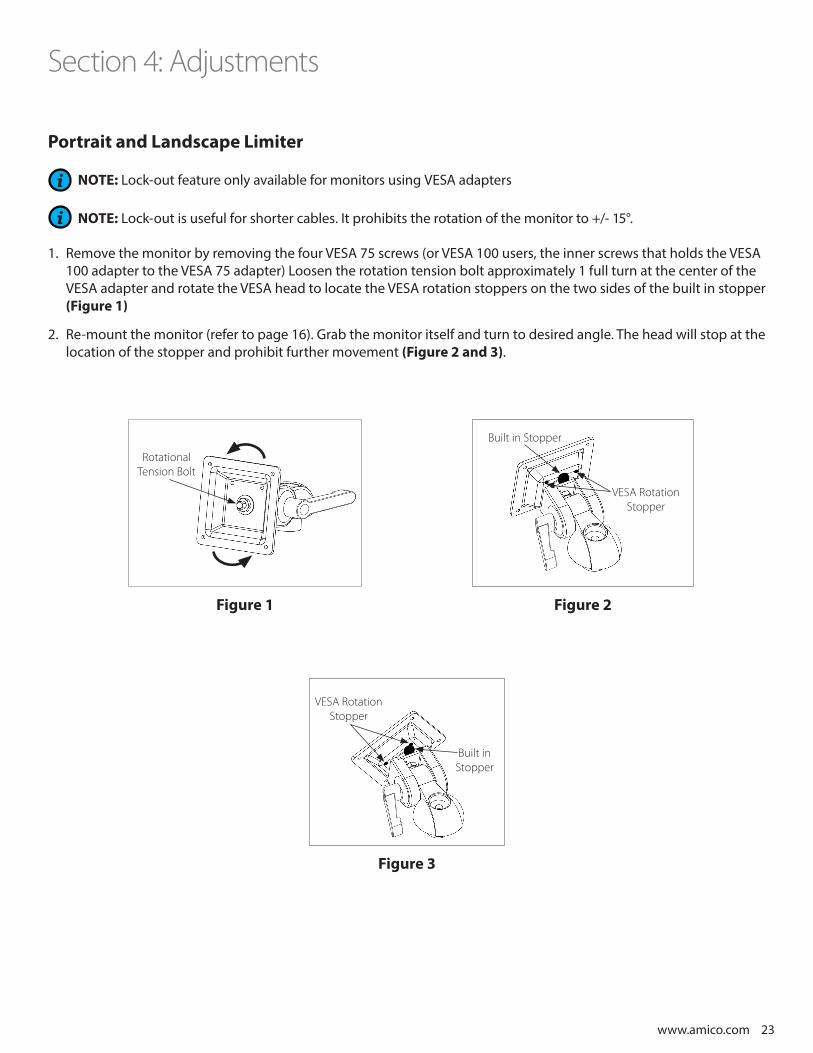
NOTE: Lock-out feature only available for monitors using VESA adapters
NOTE: Lock-out is useful for shorter cables. It prohibits the rotation of the monitor to +/- 15°.
1. Remove the monitor by removing the four VESA 75 screws (or VESA 100 users, the inner screws that holds the VESA 100 adapter to the VESA 75 adapter) Loosen the rotation tension bolt approximately 1 full turn at the center of the VESA adapter and rotate the VESA head to locate the VESA rotation stoppers on the two sides of the built in stopper (Figure 1)
2. Re-mount the monitor (refer to page 16). Grab the monitor itself and turn to desired angle. The head will stop at the location of the stopper and prohibit further movement (Figure 2 and 3).
Section 4: Adjustments
Figure 1 Figure 2
Figure 3
Rotational Tension Bolt
VESA Rotation Stopper
Built in Stopper
VESA Rotation Stopper
Built in Stopper

24 Amico Accessories Inc.
Cable Management: SSM Cable Management
NOTE: A Cable guide is provided to facilitate routing of cables along the bottom of the arm.
1. Route cables between the openings and snap them into the cable guide. Larger cables may require the cable guide be pried apart. In that case, take care not to damage the cable guide. Leave some extra cable loose at the front and rear of the arm to prevent cable binding, connector damage or cable guide damage (Figure 1).
Cable Management: MRS Rail Cover
1. Guide the cables into the center of the MRS rail, keep cables off the two sides of the MRS rail (Figure 2).
2. Guide the MRS rail cable cover into the channel over the cable. Ensuring no cable is pinched between the rail and the cover. Safely trim off any excess MRS cover after installation.
Section 4: Adjustments
Figure 1
Bottom of the SSM Arm Cable Cover
Figure 2
Direction to slide MRS Rail Cover
www.amico.com 25
Section 5: Troubleshooting, Maintenance, Product ClassificationCleaning
WARNING: THE CLEANING CHEMICALS AND METHODS BELOW ARE NOT MEANT FOR CONTROLLING ANY INFECTIONS. IT SHALL BE THE RESPONSIBILITY OF THE HOSPITAL OR THE HOSPITAL’S INFECTION CONTROL OFFICER TO SANITIZE THE EQUIPMENT.
WARNING: PLEASE DO NOT SPRAY ANY CHEMICAL DIRECTLY ONTO THE ARM. APPLY ONTO A SOFT CLOTH AND WIPE CLEAN TO PREVENT CHEMICALS GETTING INTO THE INTERNAL COMPONENTS OF THE ARM.
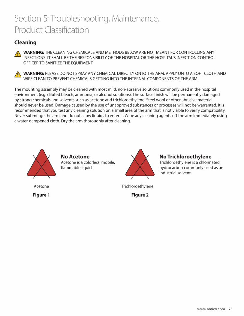
The mounting assembly may be cleaned with most mild, non-abrasive solutions commonly used in the hospital environment (e.g. diluted bleach, ammonia, or alcohol solutions). The surface finish will be permanently damaged by strong chemicals and solvents such as acetone and trichloroethylene. Steel wool or other abrasive material should never be used. Damage caused by the use of unapproved substances or processes will not be warranted. It is recommended that you test any cleaning solution on a small area of the arm that is not visible to verify compatibility. Never submerge the arm and do not allow liquids to enter it. Wipe any cleaning agents off the arm immediately using a water-dampened cloth. Dry the arm thoroughly after cleaning.
No AcetoneAcetone is a colorless, mobile, flammable liquid
No TrichloroethyleneTrichloroethylene is a chlorinated hydrocarbon commonly used as an industrial solvent
Acetone Trichloroethylene
Figure 1 Figure 2
26 Amico Accessories Inc.
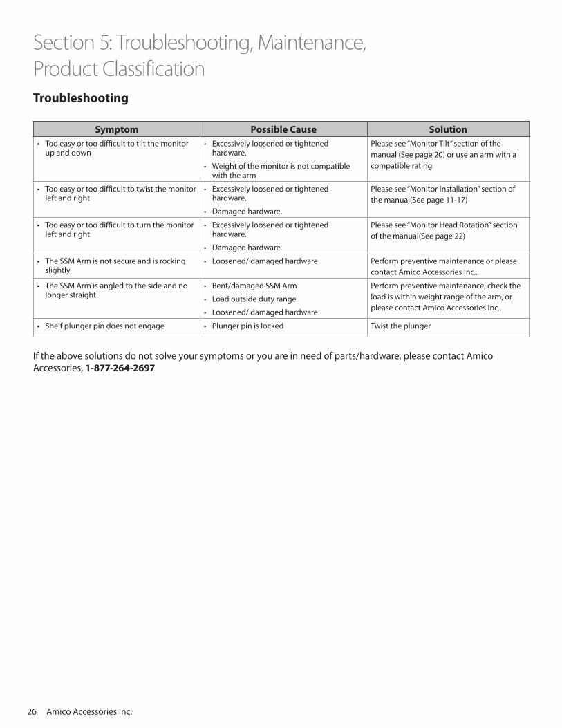
Section 5: Troubleshooting, Maintenance, Product ClassificationTroubleshooting
Symptom Possible Cause Solution• Too easy or too difficult to tilt the monitor
up and down• Excessively loosened or tightened
hardware.
• Weight of the monitor is not compatible with the arm
Please see “Monitor Tilt” section of the manual (See page 20) or use an arm with a compatible rating
• Too easy or too difficult to twist the monitor left and right
• Excessively loosened or tightened hardware.
• Damaged hardware.
Please see “Monitor Installation” section of the manual(See page 11-17)
• Too easy or too difficult to turn the monitor left and right
• Excessively loosened or tightened hardware.
• Damaged hardware.
Please see “Monitor Head Rotation” section of the manual(See page 22)
• The SSM Arm is not secure and is rocking slightly
• Loosened/ damaged hardware Perform preventive maintenance or please contact Amico Accessories Inc..
• The SSM Arm is angled to the side and no longer straight
• Bent/damaged SSM Arm
• Load outside duty range
• Loosened/ damaged hardware
Perform preventive maintenance, check the load is within weight range of the arm, or please contact Amico Accessories Inc..
• Shelf plunger pin does not engage • Plunger pin is locked Twist the plunger
If the above solutions do not solve your symptoms or you are in need of parts/hardware, please contact AmicoAccessories, 1-877-264-2697

www.amico.com 27
Section 5: Troubleshooting, Maintenance, Product ClassificationPreventive Maintenance (SSM Monitor Arm)
WARNING: SSM MONITOR ARM REQUIRES PERIODIC INSPECTION AND MAINTENANCE TO PERFORM OPTIMALLY AND ACHIEVE MAXIMUM OPERATION LIFE.
WARNING: THE INTERVALS SHOWN ON THE NEXT PAGE ARE RECOMMENDED. MAINTENANCE SCHEDULES SHOULD BE SHORTENED FOR SSM MONITOR ARM THAT SEE HEAVY USE.
Please be sure to thoroughly check the areas illustrated below for SSM Monitor Arm:
3
4
1
2

28 Amico Accessories Inc.
Section 5: Troubleshooting, Maintenance, Product Classification
Area Maintenance Period (Month)
1
2
Area 1:
A) Check if the adapter plate and the monitor are securely attached.• Mounting shelves and drop on shelf (SSM-XX (0, 2, 6, 8 and 9)) – Ensure the
screws are tight. Ensure the plunger is securely holding the adapter.
• VESA 75/100(SSM-LCD) – Ensure the four screws on the mounting plate are fastened to the tightest possible position (shown).
• Philips (SSM-XX3) – Ensure studs are securely holding the monitor
• Welch Allyn (SSM-XXW) – Ensure the thumb screw is fastened to the tightest possible position.
B) Visually inspect for any signs of grinding and gapping.
3
1
Area 2:
A) Ensure the adjustment lever is tight and secure. Also check if the plastic cover is attached firmly. Tightening will be required after prolonged use.
B) Inspect the bolt, washers and contacting surfaces for grinding and wearing. Ensure the bolt is tightened to the tightest position.
C) Check for any signs of gapping between the bushing and the head. Also ensure the head of the SSM is horizontal and is secure.
D) Inspect the bolt, washers and contacting surfaces for grinding and wearing.
1
6
6
6
3Area 3:
Ensure all the screws are fastened to the tightest possible position. Inspect for any signs of grinding, bending and gapping and ensure the SSM Arms are tightly attached together. 1
3
Area 4:
A) Inspect the bolt, washers and contacting surfaces for grinding and wearing. Ensure the bolt is tightened to the tightest position.
B) Inspect visually for any gapping between the bracket and the adapter plate. Ensure the bracket is tightly attached to the adapter plate.
MRS and Hill-Rom – Ensure the screws are fastened to the tightest possible position.
VRS – Ensure the screw knobs are fastened to the tightest possible position.
6
1
www.amico.com 29
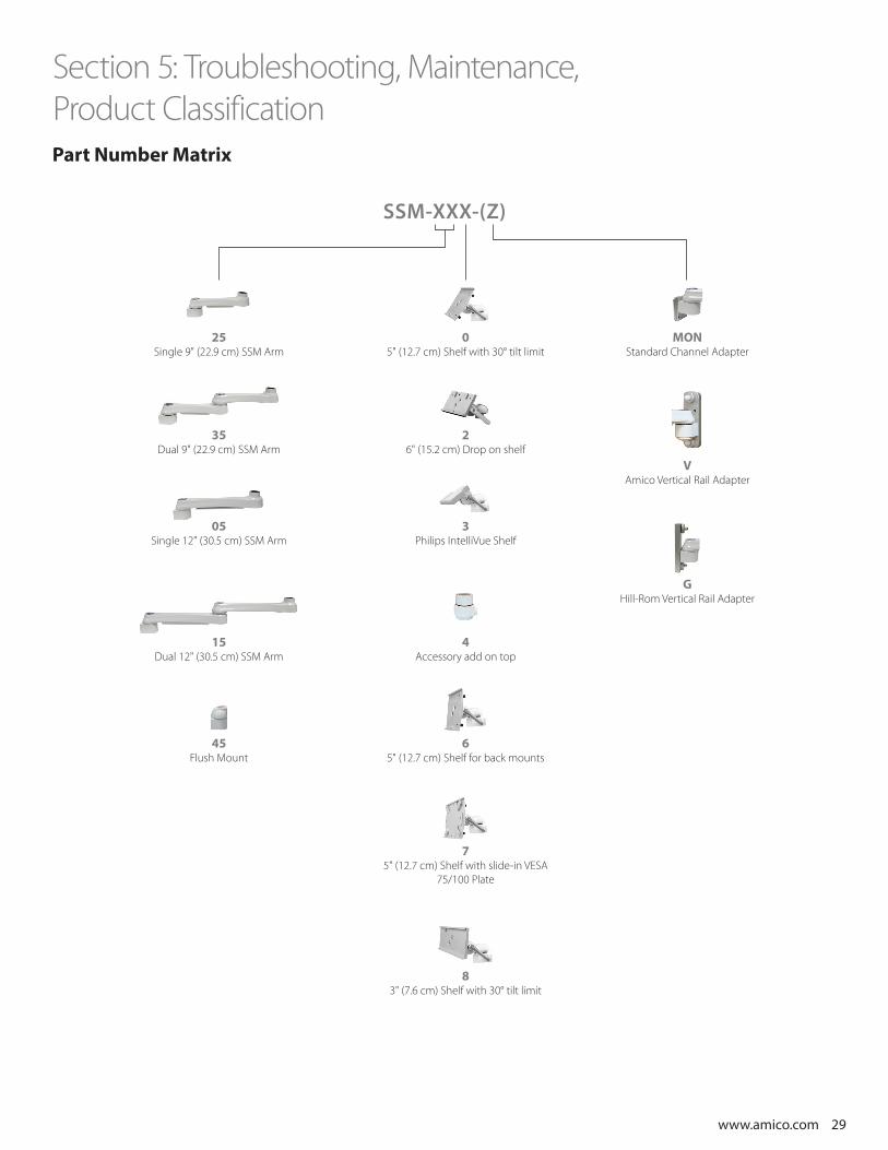
Section 5: Troubleshooting, Maintenance, Product Classification
SSM-XXX-(Z)
25Single 9" (22.9 cm) SSM Arm
35Dual 9" (22.9 cm) SSM Arm
05Single 12" (30.5 cm) SSM Arm
15Dual 12" (30.5 cm) SSM Arm
45Flush Mount
Part Number Matrix
05" (12.7 cm) Shelf with 30° tilt limit
MONStandard Channel Adapter
VAmico Vertical Rail Adapter
GHill-Rom Vertical Rail Adapter
26" (15.2 cm) Drop on shelf
3Philips IntelliVue Shelf
4Accessory add on top
65" (12.7 cm) Shelf for back mounts
83" (7.6 cm) Shelf with 30° tilt limit
75" (12.7 cm) Shelf with slide-in VESA
75/100 Plate
30 Amico Accessories Inc.
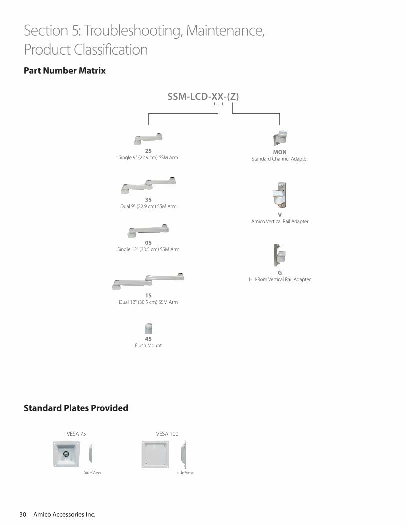
VESA 75
Side View Side View
VESA 100
SSM-LCD-XX-(Z)
Part Number Matrix
Standard Plates Provided
25Single 9" (22.9 cm) SSM Arm
MONStandard Channel Adapter
35Dual 9" (22.9 cm) SSM Arm
VAmico Vertical Rail Adapter
GHill-Rom Vertical Rail Adapter
05Single 12" (30.5 cm) SSM Arm
15Dual 12" (30.5 cm) SSM Arm
45Flush Mount
Section 5: Troubleshooting, Maintenance, Product Classification

www.amico.com 31 www.amico.com www.amico.com
Amico Accessories Inc. warrants all mounting accessories to be free from defects in material and workmanship for a period of
twelve (12) months from the date of shipment. Within this period Amico Accessories Inc. will repair or replace any part which is
proven to be defective.
Amico Accessories Inc. will warrant its materials to be free from defect for an additional period of four (4) years, (five [5] years from
the date of shipment). Within this period, Amico Accessories Inc. will replace any part which is proven to be defective, at no charge.
Shipping and Installation costs after the first twelve (12) months will be borne by the Customer.
This warranty is valid only when the product has been properly installed according to Amico Accessories Inc. specifications, used
in a normal manner and serviced according to factory recommendations. It does not cover products that are not manufactured by
Amico Accessories Inc. It does not cover failures due to damage which occurs in shipments or failures which result from accidents,
misuse, abuse, neglect, mishandling, alteration, misapplication or damage that may be attributable to acts of God.
Amico Accessories Inc. shall not be liable for incidental or consequential damages resulting from use of equipment.
All claims for warranty must first be approved by Amico Accessories Inc. A valid Return Goods Authorization (RGA) number must
be obtained from Amico Accessories Inc. prior to commencement of any service work. Warranty work, which has not been pre-
authorized by Amico Accessories Inc., will not be reimbursed.
AMICO ACCESSORIES INC. DOES NOT HONOR VERBAL STATEMENTS CONCERNING THE WARRANTY.
The distributor and/or dealer are not sanctioned to create verbal warranties about the product described in this agreement. Any
statements will not be honored or be made part of the agreement of sale. This document is the final complete and exclusive terms
of the agreement.
THIS WARRANTY IS INCLUSIVE AND REPLACES ALL OTHER WARRANTIES.
Amico Accessories Inc. shall not, under any circumstances be liable for incidental or consequential damages including, but not
limited to, profit, loss of sales or injuries to person(s) or property. Correction of noncompliance as noted above will result in
completion of all liabilities of Amico Accessories Inc., whether based on agreement, neglect or changed materials, designs or
specifications without notice.
All claims for warranty must first be approved by Amico Accessories Inc. Service Department: [email protected] or
1.877.264.2697. A valid Return Goods Authorization number must be obtained from Amico Accessories Inc. prior to commencement
of any warranty claim.
Amico Accessories Inc. 85 Fulton Way, Richmond Hill, ON L4B 2N4, CanadaTel: 905.763.7778 | Fax: 905.763.8587
Warranty Policy - Equipment Mounting Solutions
AA-WARRANTY 08.16.2017

www.amico.com
AMICO-AA-SSM-SIDE-TO-SIDE-PATIENT-MONITOR-ARM-MANUAL 05.13.2021
Amico Accessories Inc. | 85 Fulton Way, Richmond Hill, ON L4B 2N4, CanadaToll Free Tel: 1.877.264.2697 | Tel: 905.763.7778 | Fax: 905.763.8587Email: [email protected] | www.amico.com