installation instructions and owner's...
TRANSCRIPT

INSTALLATION INSTRUCTIONSAND OWNER'S MANUAL
CAST IRON UNVENTED ROOM hEATER
MODELS
SMALLVFD(10,20)CC(30,70)(B,F,M)(N,P)-1
MEDIUMVFD30CC(30,70)(B,F,M,S,W)(N,P)-1
GAS-FIRED
Installer: Leave this manual with the appliance.Consumer: Retain this manual for future reference.
This is an unvented gas-fired heater. It uses air (oxy-gen) from the room in which it is installed. Provisions for adequate combustion and ventilation air must be provided. Refer to page 7 .
WARNING: If not installed, operated and maintained in accordance with the manufacturer's instructions, this product could expose you to substances in fuel or from fuel combustion which can cause death or serious illness.
WATER VAPOR: A By-PRODUCT OF UNVENTED ROOM hEATERSWater vapor is a by-product of gas combustion. An unvented room heater produces approximately one ounce (30 ml) of water for every 1,000 BTU's (.3KW's) of gas input per hour. Refer to page 6.
This appliance may be installed in an aftermarket, permanently located, manufactured (mobile) home, where not prohibited by local codes.
This appliance is only for use with the type of gas indicated on the rating plate. This appliance is not convertible for use with other gases.
WARNING: If the information in these instruc-tions are not followed exactly, a fire or explosion may result causing property damage, personal in-jury or loss of life.
— Do not store or use gasoline or other flammable vapors and liquids in the vicinity of this or any other appliance.
— WhAT TO DO IF yOU SMELL GAS • Do not try to light any appliance. • Do not touch any electrical switch; do not use
any phone in your building. • Immediately call your gas supplier from a
neighbor’s phone. Follow the gas supplier’s instructions.
• If you cannot reach your gas supplier, call the fire department.
— Installation and service must be performed by a qualified installer, service agency or the gas sup-plier.
Page 1

31208-13-0916Page 2
section Page
iMPoRtant saFetY inFoRMation .................................................................................................... 3saFetY inFoRMation FoR UseRs oF LP-gas ............................................................................... 4intRoDUction ...................................................................................................................................... 5sPeciFications .................................................................................................................................... 6WateR VaPoR: a BY-PRoDUct oF UnVenteD RooM HeateRs ............................................... 6-7gas sUPPLY ........................................................................................................................................... 8cLeaRances ......................................................................................................................................... 9Log iDentiFication .......................................................................................................................... 10Log PLaceMent ............................................................................................................................ 11-18PLaceMent oF gLoWing eMBeRs (RocK WooL) ....................................................................... 19oPeRation instRUctions/FLaMe aPPeaRance ........................................................................ 19oPeRating gUiDeLines .................................................................................................................... 20MiLLiVoLt LigHting instRUctions ............................................................................................... 2110,000 BtU MiLLiVoLt LigHting instRUctions ........................................................................... 22PiLot FLaMe cHaRacteRistics ................................................................................................ 23-24MiLLiVoLt WiRing .......................................................................................................................... 25-26MiLLiVoLt tRoUBLesHooting ................................................................................................... 27-28iP oPeRating instRUctions .......................................................................................................... 29iP WiRing .............................................................................................................................................. 30iP LigHting instRUctions .............................................................................................................. 31iP tRoUBLesHooting .................................................................................................................. 32-34Main BURneR FLaMe cHaRacteRistics ...................................................................................... 35Maintenance ..................................................................................................................................... 36PaRts List - VFD10cc(30,70) ............................................................................................................ 37PaRts VieW - VFD10cc(30,70) .......................................................................................................... 38PaRts List - VFD20cc(30,70) ............................................................................................................ 39PaRts VieW - VFD20cc(30,70) .......................................................................................................... 40PaRts List - VFD30cc(30,70) ............................................................................................................ 41PaRts VieW - VFD30cc(30,70) .......................................................................................................... 42casting PaRts List - VFD(10,20,30)cc(30,70) ............................................................................... 43casting PaRts VieW - VFD(10,20,30)cc(30,70) ............................................................................. 44MasteR PaRts DistRiBUtoR List .................................................................................................. 45HoW to oRDeR RePaiR PaRts ........................................................................................................ 45accessoRY siDe sHeLVes instaLLation instRUctions ........................................................ 46oPtionaL stone inLaY instaLLation instRUctions ............................................................... 46ciB4-1 oPtionaL BLoWeR instaLLation instRUctions ..................................................... 47-48ciB3-1 oPtionaL BLoWeR instaLLation instRUctions ..................................................... 49-50WaRRantY ........................................................................................................................................... 51aPPLiance seRVice HistoRY ..................................................................................................... 52-53QUicK ReFeRence gUiDe ........................................................................................................... 54-55
TABLE OF CONTENTS

31208-13-0916 Page 3
ThIS IS A hEATING APPLIANCEDo not oPeRate tHis aPPLiance WitHoUt FRont PaneL instaLLeD.
IMPORTANT SAFETy INFORMATION
DANGER: indicates a hazardous situation which, if not avoided, will result in death or serious injury.
WARNING: indicates a hazardous situation which, if not avoided, could result in death or serious injury.
CAUTION: indicates a hazardous situation which, if not avoided, could result in minor or moderate injury.
NOTICE: addresses practices not related to personal injury.• An unvented room heater having an input rating of more than
6,000 Btu per hour shall not be installed in a bathroom• An unvented room heater having an input rating of more than 10,000
Btu per hour shall not be installed in a bedroom or bathroom.• Due to high temperatures, the appliance should be located out of
traffic and away from furniture and draperies.• Children and adults should be alerted to the hazard of high surface
temperature and should stay away to avoid burns or clothing ignition.
• Young children should be carefully supervised when they are in the same room with the appliance.
• Do not place clothing or other flammable material on or near the appliance.
• Avoid the use of scented air fresheners (plug in type air fresheners, etc. ) while the log set is in operation. Air fresheners produce a residue in the air similar to candles and may produce a soot like substance.
• Avoid the use of scented or decorative candles while the log set is in operation. Candles produce a residue in the air that creates a soot like substance. Burning candles while the log set is operating magnifies the problem. It should be noted that candles, in general, produce soot. The amount of time burned and the quantity of candles burned will determine the amount of soot produced and deposited.
• Installation and repair should be done by a qUALIFIED SERVICE PERSON. This appliance should be inspected before use and at least annually by a professional service person. More frequent cleaning may be required due to excessive lint from carpeting, bedding materials, etc. It is imperative that control compartments, burners and circulating air passageways of the appliance be kept clean.
• Do noT use this room heater if any part has been under water. Immediately call a qualified service technician to inspect the room heater and to replace any part of the control system and any gas control which has been under water.
• You must operate heater with fireplace screen in place. • Do not place trash, logs or other articles on the log set during
operation.• During manufacturing, fabricating and shipping, various
components of this appliance are treated with certain oils, films or bonding agents. These bonding agents are not harmful but may produce annoying smoke and smells as they are burned off during initial operation of the appliance. This is a normal temporary occurrence. A window should be opened during the initial bake out period.
• Correct installation of the ceramic fiber logs, proper location of the heater and annual cleaning are necessary to avoid potential problems with sooting. Sooting, resulting from improper installation or operation, can settle on surfaces outside the fireplace. See instructions for proper installation.
• WARnInG: Do not allow fans to blow directly into the fireplace. Avoid any drafts that alter burner flame patterns.
• WARnInG: Do not use a blower insert, heat exchanger insert or other accessory not approved for use with this heater.
• WARnInG! This fireplace needs fresh air for ventilation to run properly. This fireplace has an oDS (oxygen depletion sensor) which will shut down the heater if adequate fresh air is not available. See troubleshooting section in the instructions.
• WARNING: DO NOT operate this appliance unless all components including logs, burners, and controls are in good working condition. never operate this appliance if any log or twig is broken, or out of their intended position. Refer to the Log set placement instructions for correct log and twig positioning. Replacement components are available through your local dealer as indicated in the how to Order Repair Parts section of the appliance manual.
• Keep appliance area clear and free from combustible materials, gasoline and other flammable vapors and liquids.
• WARnInG: Failure to keep the primary air opening(s) of the burner(s) clean may result in sooting and property damage.
WARNINGWhen used without adequate combustion and ventilation air, heater may give off CARBon MonoXIDE, an odorless, poison-ous gas.
Do not install heater until all necessary provisions are made for combustion and ventilation air. Consult the writ-ten instructions provided with the heater for information concerning combustion and ventilation air. In the absence of instructions, refer to the National Fuel Gas Code, ANSI Z223.1/NFPA 54, Air for Combustion and Ventilation, or applicable local codes.
This heater is equipped with a PILOT LIGhT SAFETy SyS-TEM designed to turn off the heater if not enough fresh air is available.
DO NOT TAMPER WITh PILOT LIGhT SAFETy SySTEM!
If heater shuts off, do not relight until you provide fresh air.If heater keeps shutting off, have it serviced. Keep burner and control compartment clean.
CARBon MonoXIDE poISonInG MAY lEAD To DEATh.
Early signs of carbon monoxide poisoning resemble the flu, with headache, dizziness and/or nausea. If you have these signs, heater may not be working properly. Get fresh air at once! have heater serviced. Some people — pregnant women, persons with heart or lung disease, anemia, those under the influence of alcohol , those at high altitudes — are more affected by carbon monoxide than others.The pilot light safety system senses the depletion of oxygen at its location. If this heater is installed in a structure having a high vertical dimension, the possibility exists that the oxygen supply at the higher levels will be less than that at the heater. In this type of application, a fan to circulate the structure air will minimize this effect. The use of this fan will also improve the comfort level in the structure. When a fan is used to circulate air, it should be located so that the air flow is not directed at the burner.

31208-13-0916Page 4
SOME POINTS TO REMEMBER
NO ODOR DETECTED - ODOR FADE
LP-GAS WARNING ODORIf a gas leak happens, you should be able to smell the gas because of the odorant put in the lp-Gas.
That's your signal to go into immediate action!
propane (lp-Gas) is a flammable gas which can cause fires and explosions. In its natural state, propane is odorless and colorless. You may not know all the following safety precau-tions which can protect both you and your family from an accident. Read them carefully now, then review them point by
point with the members of your household. Someday when there may not be a minute to lose, everyone's safety will depend on knowing exactly what to do. If, after reading the following information, you feel you still need more information, please contact your gas supplier.
• Donotoperateelectricswitches,lightmatches,useyourphone.Do not do anything that could ignite the gas.
•Geteveryoneoutofthebuilding,vehicle,trailer,orarea.DothatiMMeDiateLY.
•Closeallgastankorcylindersupplyvalves.•LP-Gasisheavierthanairandmaysettleinlowareassuchasbasements.Whenyouhavereasontosuspectagasleak,keepoutofbasementsandotherlowareas.Stayoutuntilfirefightersdeclarethemtobesafe.
•Useyourneighbor'sphoneandcallatrainedLP-Gasservice
personandthefiredepartment.Eventhoughyoumaynotcon-tinue to smell gas, do not turn on the gas again. Do not re-enter thebuilding,vehicle,trailer,orarea.
• Finally, lettheservicemanandfirefighterscheckforescapedgas.Have themairout theareabeforeyou return.ProperlytrainedLP-Gasservicepeopleshouldrepairtheleak,thencheckand relight the gas appliance for you.
Some people cannot smell well. Some people cannot smell the odor of the chemical put into the gas. You must find out if you can smell the odorant in propane.Smokingcandecreaseyourabilitytosmell.Beingaroundanodorforatimecanaffectyoursensitivityorabilitytodetectthatodor.Sometimesotherodorsintheareamaskthegasodor.Peoplemaynotsmellthegasodorortheirmindsareonsomethingelse.Thinkingaboutsmellingagasodorcanmakeiteasiertosmell.
The odorant in LP-gas is colorless, and it can fade under some circumstances.Forexample,ifthereisanundergroundleak,themovementofthegasthroughsoilcanfiltertheodorant.OdorantsinLP-Gasalsoaresubjecttooxidation.Thisfadingcanoccurif
thereisrustinsidethestoragetankorinirongaspipes.
Theodorantinescapedgascanadsorborabsorbontoorintowalls,masonryandothermaterialsandfabricsinaroom.Thatwilltakesome of the odorant out of the gas, reducing its odor intensity.
LP-gas may stratify in a closed area, and the odor intensity could varyatdifferentlevels.Sinceitisheavierthanair,theremaybemoreodoratlowerlevels.Alwaysbesensitivetotheslightestgasodor.Ifyoudetectanyodor,treatitasaseriousleak.Immediatelygo into action as instructed earlier.
• learn to recognize the odor of lp-gas. Your local LP-gas Dealer can give you a "scratch and sniff" pamphlet. Use it to findoutwhatthepropaneodorsmellslike.IfyoususpectthatyourLP-Gashasaweakorabnormalodor,callyourLP-GasDealer.
• Ifyouarenotqualified,donotlightpilotlights,performservice,ormakeadjustmentstoappliancesontheLP-Gassystem.Ifyouarequalified,consciouslythinkabouttheodorofLP-Gasprior to and while lighting pilot lights or performing service or makingadjustments.
• Sometimes a basement or a closed-up house has a mustysmell that can cover up the LP-gas odor. Do not try to light pilot lights,performservice,ormakeadjustmentsinanareawherethe conditions are such that you may not detect the odor if there hasbeenaleakofLP-Gas.
• Odorfade,duetooxidationbyrustoradsorptiononwallsofnewcylindersandtanks,ispossible.Therefore,peopleshouldbeparticularlyalertandcarefulwhennewtanksorcylindersareplacedinservice.Odorfadecanoccurinnewtanks,orreinstalledoldtanks,iftheyarefilledandallowedtosettoolongbeforerefilling.Cylindersandtankswhichhavebeenoutofservicefora time may develop internal rust which will cause odor fade. if
such conditions are suspected to exist, a periodic sniff test of thegasisadvisable.If you have any question about the gas odor, call your LP-gas dealer. A periodic sniff test of the LP-gas is a good safety measure under any condition.
• If,atanytime,youdonotsmelltheLP-Gasodorantandyouthinkyoushould,assumeyouhavealeak.Thentakethesameimmediateactionrecommendedabovefortheoccasionwhenyou do detect the odorized LP-gas.
• Ifyouexperienceacomplete"gasout,"(thecontainerisundernovaporpressure),turnthetankvalveoffimmediately.Ifthecontainer valve is left on, the container may draw in some air throughopeningssuchaspilotlightorifices.Ifthisoccurs,somenew internal rusting could occur. if the valve is left open, then treatthecontainerasanewtank.Alwaysbesureyourcontainerisundervaporpressurebyturningitoffatthecontainerbeforeitgoescompletelyemptyorhavingitrefilledbeforeitiscompletelyempty.
SAFETy INFORMATION FOR USERS OF LP-GAS

31208-13-0916 Page 5
safe when installed in accordance with this installation Manual. Reporttoyourdealeranypartsdamagedinshipment,specificallychecklogplacement.Donotinstallunitwithdamaged,incomplete,orsubstituteparts.Readallinstructionsbeforestartinginstallationand follow these instructions carefully during installation to insure maximumbenefitandsafety.Failuretofollowthemwillvoidyourwarrantyandmaypresentafirehazard.
Thewarrantywillbevoidedby,and thewarranterdisclaimsanyresponsibilityforthefollowingactions:• Installationofanydamagedfireplace.• Modificationofthefireplace.• InstallationotherthanasinstructedbyEmpireComfortSystems
inc.• Improperpositioningofthelogs.• Installationand/oruseofanycomponentpartnotmanufactured
orapprovedbymanufacturer.Qualified Installing AgencyInstallationandreplacementofgaspiping,gasutilizationequipmentoraccessoriesandrepairandservicingofequipmentshallbeperformedonlybyaqualifiedagency.Theterm"qualifiedagency"meansanyindividual,firm,corporationorcompanywhicheitherinpersonorthrougharepresentativeisengagedinandisresponsiblefor(a)theinstallationorreplacementofgaspipingor(b)theconnection,installation,repairorservicingofequipment,whoisexperiencedinsuchwork,familiarwithallprecautionsrequiredandhascompliedwithalltherequirementsoftheauthorityhavingjurisdiction.
State of Massachusetts: The installationmust bemadeby a licensed plumber or gas fitter in theCommonwealth ofMassachusetts.
Sellersofunventedpropaneornaturalgas-firedsupplementalroom heaters shall provide to each purchaser a copy of 527 cMR 30 upon sale of the unit. in the state of Massachusetts, unvented propaneornaturalgasfiredspaceheatersshallbeprohibitedinbedroomsandbathrooms.
Theinstallationmustconformwithlocalcodesor,intheabsenceoflocal codes, with the National Fuel Gas Code, ANSI Z223.1/NFPA 54.**Available from the American National Standards Institute, Inc., 11 West 42nd St., New York, N.Y. 10036.
WARNINGanY cHange to tHis FiRePLace oR its contRoLs can Be DangeRoUs.
Improper installation or use of the fireplace can cause serious injury or death from fire, burns, explosions, or carbon monoxide poisoning.Any alteration of the original design, installed other than shown in these instructions or use with a type of gas not shown on the rating plate is the responsibility of the person and company making the change.high AltitudesForaltitudes/elevationsabove2,000feet(610m),ratingsshouldbereducedattherateof4percentforeach1,000feet(305m)abovesealevel.Contactthemanufactureroryourgascompanybeforechangingspud/orificesize.
always consult your local Building Department regarding regulations, codes or ordinances which apply to the installation of an unvented room heater.Thisappliancemaybe installed inanaftermarket*permanentlylocated, manufactured (mobile) home, where not prohibited bystate or local codes.*Aftermarket:Completionofsale,notforpurposeofresale,from
the manufacturer.this appliance is only for use with the type of gas indicated on the rating plate.Instructions to Installer1. installer must leave instruction manual with owner after
installation.2. Installermusthaveownerfilloutandmailproductregistration
card supplied with unvented room heater.3. installer should show owner how to start and operate unvented
room heater.ThisproductisdesigncertifiedinaccordancewithAmericanNationalStandardsInstituteZ21.11.2byUnderwritersLaboratories(UL)asanUnventedRoomHeaterandshouldbeinstalledaccordingtothese instructions.NOTICE: Removescrewinvalvecover.Screwisrequiredtopreventshipping damage.Attention: During initial use of ceramic log you will detect an odor as the ceramic log is cured. Any alteration of the original design, installed other than as shown in these instructions or use with a type of gas not shown on the rating plate is the responsibility of the person and company making the change. Do not operate this appliance unless all components including logs, burners, and controls are in good working condition. never operate this appliance if any log or twig is broken, or out of their intended position. Refer to Log Placement on pages 10 - 11 for correct log and twig positioning. Replacement parts are available through your local dealer as indicated in the Parts Sections on pages 30 through 37.
WARNINGThis appliance is equipped for (natural or propane) gas. Field conversion is not permitted.
WARNINGThis unit is not for use with solid fuels.
ImportantAllcorrespondenceshouldrefertocompleteModelNumber,SerialNumberandtypeofgas.Notice:Duringinitialfiringofthisunit,itspaintwillbakeout,andsmokemayoccur.Topreventtriggeringofsmokealarms,ventilatethe room in which the unit is installed.Installation in Residential GaragesGasutilizationequipmentinresidentialgaragesshallbeinstalledsothatallburnersandburnerignitiondevicesarelocatednotlessthan18"(457mm)abovethefloor.Suchequipmentshallbelocated,orprotected,soitisnotsubjecttophysicaldamagebyamovingvehicle.PreparationThisvent freegasfireplaceand its componentsare testedand
INTRODUCTION

31208-13-0916Page 6
Watervaporisaby-productofgascombustion.Anunventedroomheater produces approximately one ounce (30 ml) of water for every 1,000BTU's(.3KW's)ofgasinputperhour.
Unvented room heaters must be used as supplemental heat (a room) rather than a primary heat source (an entire house). in most supplemental heat applications, the water vapor does not create a problem.Inmostapplications,thewatervaporenhancesthelowhumidity atmosphere experienced during cold weather.
the following steps will help insure that water vapor does not becomeaproblem.1. Be sure the heater is sized properly for the application, including
amplecombustionairandcirculationair.2. Ifhighhumidityisexperienced,adehumidifiermaybeusedto
help lower the water vapor content of the air.3. Do not use an unvented room heater as the primary heat source
(an entire house).
WATER VAPOR: A By-PRODUCT OF UNVENTED ROOM hEATERS
AccessoriesFRBc Battery operated Remote controlFRBtc Battery operated Remote control w/thermostatFRBtP 7-DayProgrammableRemoteFRec electric Remote controlFWs Wall switchtMV Millivolt Wall thermostat - Reed switchtRW Remote Wall thermostatciB4 automatic Blower (VFD(10,20)cc Units)ciB3 automatic Blower (VFD30cc Units)stone inlay Replaces standard grill top (Medium Units only)csi-8V stone inlay Venetian goldcsi-9a stone inlay AdobeFrostcsi-10M stone inlay Patina Mochacsi-11g stone inlay temple graycsi-12a stone inlay american Beauty
SPECIFICATIONSModel VFD10CCinput BtU/HR (KW/H) Maximum 10,000input BtU/HR (KW/H) Minimum 10,000Height 24 1/8" (612.8 mm)Width 21 1/2" (546.1 mm)Depth 15 3/8" (390.5 mm)gas inlet 3/8" (9.5 mm)air shutter setting (nat) 1/16" air shutter setting (LP) 1/4"Model VFD20CCinput BtU/HR (KW/H) Maximum (LP) 20,000input BtU/HR (KW/H) Minimum (LP) 16,000input BtU/HR (KW/H) Maximum (nat) 20,000input BtU/HR (KW/H) Minimum (nat) 14,500Height 24 1/8" (612.8 mm)Width 21 1/2" (546.1 mm)Depth 15 3/8" (390.5 mm)gas inlet 3/8" (9.5 mm)air shutter setting (nat) 1/8"air shutter setting (LP) 3/8"Model VFD30CCinput BtU/HR (KW/H) Maximum (LP) 25,000input BtU/HR (KW/H) Minimum (LP) 21,000input BtU/HR (KW/H) Maximum (nat) 25,000input BtU/HR (KW/H) Minimum (nat) 17,500Height 27 3/4" (704.9 mm)Width 28 1/16" (712.8 mm)Depth 17 1/8" (435.0 mm)gas inlet 3/8" (9.5 mm)air shutter setting (nat) 1/16"air shutter setting (LP) 7/16"
Accessories
Model DescriptionAvailable on Models
VFD(10,20)CC VFD30CC
csK-B side shelfPorcelainBlack X X
csK-F side shelf MatteBlack X X
csK-M side shelf Porcelain Mahogany X X
csK-s side shelf Porcelain sand X
csK-W side shelf Matte Pewter X

31208-13-0916 Page 7
Thisheatershallnotbeinstalledinaconfinedspaceorunusuallytight construction unless provisions are provided for adequatecombustionandventilationair.
Aconfinedspaceisanareawithvolumelessthan50cubicfeetper1,000Btuhofthecombinedinputratesofallappliancesdrawingcombustionairfromthatspace.Smallareassuchasequipmentroomsareconfinedspaces.Furnacesinstalledinaconfinedspacewhich supply heated air to areas outside the space must draw return air from outside the space through tightly sealed return air ducts. a confinedspacemusthave2openingsintothespaceforcombus-tionair.Oneopeningmustbewithin12inchesoftheceilingandtheothermustbewithin12inchesofthefloor.Therequiredsizingoftheseopeningsisdeterminedbywhetherinsideoroutsideairisusedtosupportcombustion,themethodbywhichtheairisbroughttothespace(verticalorhorizontalduct)andbythetotalinputrateof all appliances in the space.
the following example is for determining the volume of a typical areainwhichtheVFD30maybelocatedandfordeterminingifthisareafitsthedefinitionofanunconfinedspace.
the maximum input of the VFD30 is 25,000 Btu per hour. Based onthe50cubicfeetper1,000Btuperhourformula,theminimum areathatisanunconfinedspaceforinstallationoftheVFD30is1,250cubicfeet,50cubicfeetx25=1,250cubicfeet.TodeterminethecubicfeetoftheareainwhichtheVFD30istobeinstalled,measure the length, width and height of the area. example: the area measures 16 feet in length, 10 feet in width and 8 feet in height,theareais1,280cubicfeet.TheVFD30canbeinstalledinthisunconfinedspacewithnorequirementtoprovideadditionalcombustionandventilationair.
PROVISIONS FOR ADEqUATE COMBUSTION & VENTILATION AIR
WARNINGIftheareainwhichtheheatermaybeoperatedissmallerthanthatdefinedasanunconfinedspaceorifthebuildingisofunusuallytightconstruction,provideadequatecombustionandventilationairbyoneofthemethodsdescribedintheorapplicablelocalcodes.
Unusually Tight ConstructionTheairthatleaksarounddoorsandwindowsmayprovideenoughfreshairforcombustionandventilation.However,inbuildingsofunusually tight construction, you must provide additional fresh air. Unusually tight construction is defined as construction
where:a. Walls and ceilings exposed to the outside atmosphere have
a continuous water vapor retarder with a rating of one perm orlesswithopeningsgasketedorsealed,and
b. Weather-strippinghasbeenaddedonopenablewindowsand doors, and
c. Caulking or sealants are applied to areas such as jointsaroundwindowanddoorframes,betweensoleplatesandfloors,betweenwall-ceilingjoints,betweenwallpanels,atpenetrationsforplumbing,electrical,andgaslines,andatother openings.
IftheVFD30heaterisinstalledinabuildingofunusuallytightcon-struction,adequateairforcombustion,ventilationanddilutionoffluegasesshallbeprovidedinaccordancewithANSIZ223.1/NFPA54.
31208-13-0916Page 8
Checkalllocalcodesforrequirements,especiallyforthesizeandtypeofgassupplylinerequired.
Recommended Gas Pipe DiameterPipe Length schedule 40 Pipe
inside DiameterTubing,TypeL
outside Diameternat. L.P. nat. L.P.
0-10 feet0-3 meters
1/2”12.7 mm
3/8”9.5 mm
1/2”12.7 mm
3/8”9.5 mm
10-40 feet4-12 meters
1/2”12.7 mm
1/2”12.7 mm
5/8”15.9 mm
1/2”12.7 mm
40-100 feet13-30 meters
1/2”12.7 mm
1/2”12.7 mm
3/4”19 mm
1/2”12.7 mm
100-150 feet31-46 meters
3/4”19 mm
1/2”12.7 mm
7/8”22.2 mm
3/4”19 mm
NOTICE:Neveruseplasticpipe.Checktoconfirmwhetheryourlocalcodesallowcoppertubingorgalvanized.
NOTICE: since some municipalities have additional local codes, it isalwaysbesttoconsultyourlocalauthorityandinstallationcode.
Installing a new Main Gas Cock Eachapplianceshouldhaveitsownmanualgascock.Amanualmaingascockshouldbelocatedinthevicinityoftheunit.Wherenoneexists,orwhereitssizeorlocationisnotadequate,contact your local authorized installer for installation or relocation.Compoundsusedonthreadedjointsofgaspipingshallberesistanttotheactionofliquefiedpetroleumgases.Thegaslinesmustbecheckedforleaksbytheinstaller.Thisshouldbedonewithasoapsolutionwatchingforbubblesonallexposedconnections,and ifunexposed,apressuretestshouldbemade.never use an exposed flame to check for leaks. Appliance must be disconnected from piping at inlet of control valve and pipe capped or plugged for pressure test. Never pressure test with appliance connected; control valve will sustain damage!Agasvalveandgroundjointunionshouldbeinstalledinthegaslineupstreamofthegascontroltoaidinservicing.ItisrequiredbytheNationalFuelGasCodethatadriplinebeinstallednearthegasinlet. this should consist of a vertical length of pipe tee connected intothegaslinethatiscappedonthebottominwhichcondensationand foreign particles may collect.
the use of the following gas connectors is recommended:
— ANSZ21.24ApplianceConnectorsofCorrugatedMetalTubingand Fittings
— ANSZ21.45AssembledFlexibleApplianceConnectorsofOtherthan all-Metal construction
TheaboveconnectorsmaybeusedifacceptablebytheauthorityhavingjurisdictionThestateofMassachusettsrequiresthataflexibleappliance connector cannot exceed three feet in length.
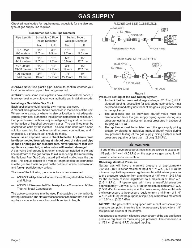
GAS SUPPLy
Figure 1pressure Testing of the Gas Supply System1. Tochecktheinletpressuretothegasvalve,a1/8"(3mm)N.P.T.
pluggedtapping,accessiblefortestgaugeconnection,mustbeplacedimmediatelyupstreamofthegassupplyconnectionto the appliance.
2. The appliance and its individual shutoff valve must bedisconnected from the gas supply piping system during any pressure testing of that system at test pressures in excess of 1/2psig(3.5kPa).
3. Theappliancemustbe isolated from thegas supplypipingsystembyclosing its individualmanualshutoffvalveduringany pressure testing of the gas supply piping system at test pressuresequaltoorlessthan1/2psig(3.5kPa).
WARNINGIfoneoftheaboveproceduresresultsinpressuresinexcessof1/2psig(14"w.c.)(3.5kPa)ontheappliancegasvalve,itwillresult in a hazardous condition.
Checking Manifold pressurenatural gas will have a manifold pressure of approximately 3.5"w.c.(.871kPa)formaximuminputor1.7"w.c.(.423kPa)forminimum input at the pressure regulator outlet with the inlet pressure tothepressureregulatorfromaminimumof4.5"w.c.(1.245kPa)for the purpose of input adjustment to a maximum of 10.5" w.c. (2.614 kPa). Propane gas will have a manifold pressureapproximately10.0"w.c.(2.49kPa)formaximuminputor6.3"w.c.(1.568kPa)forminimuminputatthepressureregulatoroutletwiththe inlet pressure to the pressure regulator from a minimum of 11.0" w.c.(2.739kPa)forthepurposeofinputadjustmenttoamaximumof13.0"w.c.(3.237kPa).
NOTICE: Thegascontrolisequippedwithacapturedscrewtypepressure test point, therefore it is not necessary to provide a 1/8" test point up stream of the control.
a test gauge connection is located downstream of the gas appliance pressure regulator for measuring gas pressure. the connection is a 1/8 inch (3 mm) n.P.t. plugged tapping.
31208-13-0916 Page 9
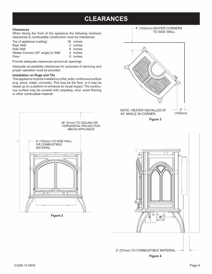
ClearancesWhen facing the front of the appliance the following minimum clearancestocombustibleconstructionmustbemaintained.top of appliance (ceiling) 36 inchesRear Wall 2 inchesside Wall 6 inchesHeater corners (45° angle) to Wall 4 inchesFloor 0 inchesProvideadequateclearancesaroundairopenings.Adequateaccessibilityclearancesforpurposesofservicingandproperoperationmustbeprovided.Installation on Rugs and TileThisappliancemustbeinstalledonaflat,solid,continuoussurface(e.g.wood,metal,concrete).Thismaybethefloor,oritmayberaised up on a platform to enhance its visual impact. the continu-oussurfacemaybecoveredwithcarpeting,vinyl,woodflooringorothercombustiblematerial.
CLEARANCES
Figure 2
Figure 3
Figure 4
31208-13-0916Page 10
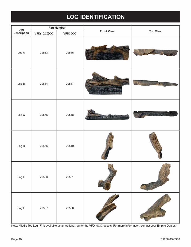
Note:MiddleTopLog(F)isavailableasanoptionallogfortheVFD10CClogsets.Formoreinformation,contactyourEmpireDealer.
Log Description
Part NumberFront View Top View
VFD(10,20)CC VFD30CC
Log a 29553 29546
Log B 29554 29547
Log c 29555 29548
Log D 29556 29549
Log e 29558 29551
Log F 29557 29550
LOG IDENTIFICATION

31208-13-0916 Page 11
LOG PLACEMENT
CAUTIONDonotchangetheangleofthetwoLogLocatingTabsontherearlogshelforthetwoLogLocatingTabsontheburnerbase.Doing so will cause misalignment of logs.
WARNINGFailure to position the parts in accordance with this diagram or failure touseonlypartsspecificallyapprovedwith thisheatermay result in property damage or personal injury.
note: For step by step log placement instructions with im-ages, see pages 12-18.
Figure 6 - Log Placement
Figure 5 - Burner
Figure 7 - Completed Log Placement

31208-13-0916Page 12
1. PlaceLogAontothetwoLogLocatingTabsontherearlogshelfasshownbelow.
LOG PLACEMENT

31208-13-0916 Page 13
2. PlaceLogBbehindthetwoLogLocatingTabsontheburnerbaseasshownbelow.
LOG PLACEMENT

31208-13-0916Page 14
3. PlaceLogContothetwoLogLocatingExtensionsontheburnerbodyasshownbelow.
LOG PLACEMENT

31208-13-0916 Page 15
4. PlaceLogDontotheleftpinonLogA.TheendofLogDwillrestonLogCasshownbelow.
LOG PLACEMENT

31208-13-0916Page 16
5. PlaceLogEontherightpinonLogA.TheendofLogEwillrestintherightflatareaonLogCasshownbelow.
LOG PLACEMENT

31208-13-0916 Page 17
6. Thisstepisoptionalfor10,000BTUunits.PlaceLogFnexttotherightnubonLogBandtheleftflatareaonLogC.Seeimagebelow.
LOG PLACEMENT

31208-13-0916Page 18
7. Logassemblyiscompleted.
LOG PLACEMENT

31208-13-0916 Page 19
Providedwiththelogsetisasmallbagofglowingembers(rockwool)tobeplacedbetweenlogsontheflatmetalsurfaceoftheburner.Placementof theembers(rockwool) isvery individualand lightcoverageoftheareasindicatedwillprovideyourbesteffects.Werecommendseparationoftherockwoolbyhandandmakeyourcoverageaslightandfluffyaspossible.
Placejustenoughembers(rockwool)ontheburnertoobtaintheglowandagoldyellowflame.
Donotplacerockwooloverlargeportsinrearportionofburner.
A thin layer of rockwool should be placed under open spacebetweenthefrontandmiddlelogs.
Rockwoolshouldnotbeplacedintheareaofthepilotassembly.
Replacementofloosematerial(glowingembers)mustbepurchasedfrom empire comfort systems, inc. application of excess loose material (glowingembers)mayadversely affect performanceofthe heater.
WARNINGAllpreviouslyappliedloosematerialmustberemovedpriortoreapplication.
NOTICE:Asingle layerofembers is tobeusedwhenapplyingPlatinumBrightEmbers(aloneorincombinationwithproductionembers)totheburner.
Replacement Loose Material (glowing embers) Part Number
RockWool-VFD10CC 31104RockWool-VFD(20,30)CC 15998PlatinumBrightEmbers Pe-20-1
Flamesfromthepilot(rearrightbacksideoftheburner)aswellasthemainflameshouldbevisuallycheckedasthelogsetisinstalled.Innormaloperationat fullrateafter10to15minutes,theflameappearanceshouldbesetsofyellowflames.NOTICE:Allflameswillberandombydesign,flameheightwillgoup and down.Glowing embers (rockwool) can cover the burner in betweenthefrontandmiddlelogs,butverylittleisnecessarytocoverthisarea.Excessembermaterialcausestheyellowflametobecomeorangeandstringy.Applyjustenoughtoobtainslowglowandagold,yellowflame.Avoidanydraftsthatalterburnerflamepatterns.Donotallowfanstoblowdirectlyintofireplace.Donotplaceablowerinsidetheburnerareaofthefirebox.Ceilingfansmaycreatedraftsthatalterflamepatterns.Sootingandimproperburningwillresult.
Duringmanufacturing,fabricatingandshipping,variouscomponentsofthisappliancearetreatedwithcertainoils,filmsorbondingagents.Thesechemicalsarenotharmful,butmayproduceannoyingsmokeandsmellsastheyareburnedoffduringtheinitialoperationoftheappliance,possiblycausingheadachesoreyeorlungirritation.Thisis a normal and temporary occurrence.Theinitialbreak-inoperationshouldlast2-3hourswiththeburnerat thehighest setting.Providemaximumventilationby openingwindows or doors to allow odors to dissipate. any odors remaining after this initial break-inwill be slight andwill disappear withcontinued use.
plACEMEnT oF GloWInG EMBERS (RoCK Wool)
OPERATION INSTRUCTIONS/FLAME APPEARANCE
Figure 8

31208-13-0916Page 20
Standing Pilot Operation1. Follow the saFetY and LigHting instRUctions for standing
pilotcontrolsfoundinthismanualandonlabelsfoundattachedto the appliance.
CAUTIONDuring the initial purging and subsequent lightings, never allow the gas valve control knob to remain depressed in the "pilot" position without pushing the piezo ignitor button at least once every second.
2. Duringtheheatingseason,leavethecontrolvalveknobinthe"ON"position.Thiswillallowthepilotflametoremainlit.TurntheburnerflameonoroffwiththeapplianceREMOTE/OFF/ONrockerswitch,wallswitch,remotecontrolkitsor750millivoltwallthermostat.
Figure 9
NOTICE: the gas control valve allows you to increase or decrease theheightofthemainburnerflame.ThecontrolvalvehasapressureregulatorwithaknobasshowninFigure9.Rotatetheknobclockwiseto"HI"toincreasetheflameheightandcounterclockwiseto"LO"todecreasetheflameheight.3. When the heating season is over, turn the ReMote/oFF/on
switch to "oFF" and the control valve to "oFF". the system, includingthepilotlight,willbeshutdown.
Maximum and Minimum InputThegasvalveontheapplianceallowstheinputtoadjustbetweena maximum input of 25,000 Btuh to a minimum input of 17,500 Btuh.Pleasebeadvised,themaximuminputprovidesthegreatestamountofyellowflameandemberglowonthelogset.Theminimuminputsubstantiallydecreasestheyellowflameandemberglowonthe log set.
Before operating this heater, please review the safety warnings pagesatthebeginningofthismanualandthoseprecautionsandwarningslistedbelow.1. Know what type of ignition system this model has (standing
pilot) and follow the applicable SAFETY and LIGHTINGinstructions.
2. Check to ensure there are no gas leaks. If you are unsure,turn gas off to the heater and call a service person or your gas utility.
CAUTIONClothing or other flammable material should not be placed on or near the appliance.
WARNINGChildren and adults should be alerted to the hazard of high surface temperature and should stay away to avoid burns or clothing ignition. Young children should be carefully supervised when they are in the same room as the appliance.
3. tampering is DangeRoUs and voids all warranties. any componentthatisfoundtobefaulty,mustbereplacedwithanapproved component.
Initial LightingUpon completing the gas line or turning the gas valve "on" after it hasbeeninthe"OFF"position,asmallamountofairwillbeinthelines.Whenfirstlightingtheappliance,itwilltakeafewminutesfor the lines to purge themselves of this air. once the purging is complete, the appliance will light and operate satisfactorily.Subsequentlightingsoftheappliancewillnotrequiresuchpurgingif the gas valve is not turned to "oFF."
OPERATING GUIDELINES

31208-13-0916 Page 21
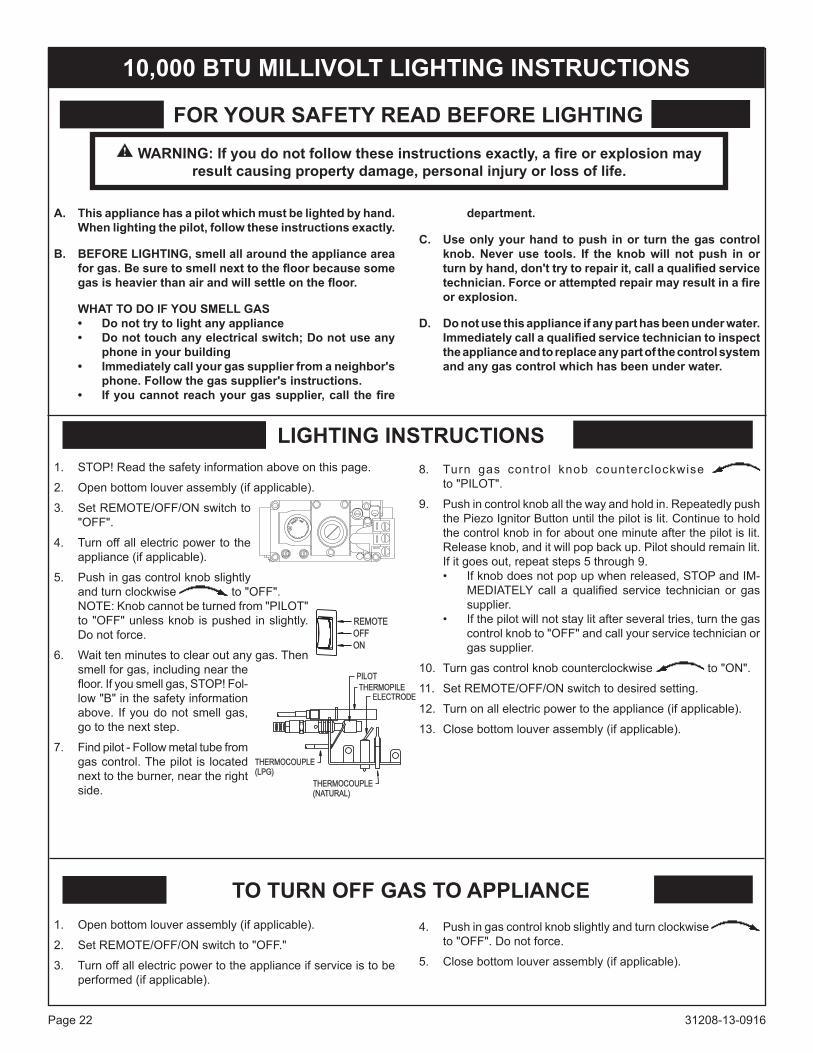
MILLIVOLT LIGhTING INSTRUCTIONS
WARNING: If you do not follow these instructions exactly, a fire or explosion may result causing property damage, personal injury or loss of life.
A. This appliance has a pilot which must be lighted by hand. When lighting the pilot, follow these instructions exactly.
B. BEFORE LIGhTING, smell all around the appliance area for gas. Be sure to smell next to the floor because some gas is heavier than air and will settle on the floor.
WhAT TO DO IF yOU SMELL GAS • Do not try to light any appliance • Do not touch any electrical switch; Do not use any
phone in your building • Immediately call your gas supplier from a neighbor's
phone. Follow the gas supplier's instructions. • If you cannot reach your gas supplier, call the fire
department.
C. Use only your hand to push in or turn the gas control knob. never use tools. If the knob will not push in or turn by hand, don't try to repair it, call a qualified service technician. Force or attempted repair may result in a fire or explosion.
D. Do not use this appliance if any part has been under water. Immediately call a qualified service technician to inspect the appliance and to replace any part of the control system and any gas control which has been under water.
1. Openbottomlouverassembly(ifapplicable).
2. set ReMote/oFF/on switch to "oFF."
3. Turnoffallelectricpowertotheapplianceifserviceistobeperformed(ifapplicable).
4. Pushingascontrolknobslightlyandturnclockwise to "oFF". Do not force.
5. Closebottomlouverassembly(ifapplicable).
1. STOP!Readthesafetyinformationaboveonthispage.
2. Openbottomlouverassembly(ifapplicable).
3. set ReMote/oFF/on switch to "oFF".
4. turn off all electric power to the appliance(ifapplicable).
5. Pushingascontrolknobslightlyand turn clockwise to "oFF". NOTE:Knobcannotbeturnedfrom"PILOT"to"OFF"unlessknob ispushed inslightly.Do not force.
6. Wait ten minutes to clear out any gas. then smell for gas, including near the floor. If you smell gas,stoP! Follow "B" in the safety informationabove.Ifyoudonotsmell gas, go to the next step.
7. Findpilot-Followmetaltubefromgas control. the pilot is located nexttotheburner,neartherightside.
8. Turn gas control knob counterclockwise to "PiLot".
9. Pushincontrolknoballthewayandholdin.Repeatedlypushthe Piezo ignitor Button until the pilot is lit. continue to hold thecontrolknobinforaboutoneminuteafterthepilotislit.Releaseknob,anditwillpopbackup.Pilotshouldremainlit.if it goes out, repeat steps 5 through 9.
• Ifknobdoesnotpopupwhenreleased,STOPandIM-MEDIATELYcall a qualified service technicianor gassupplier.
• Ifthepilotwillnotstaylitafterseveraltries,turnthegascontrolknobto"OFF"andcallyourservicetechnicianorgas supplier.
10. Turngascontrolknobcounterclockwise to "on".
11. set ReMote/oFF/on switch to desired setting.
12. Turnonallelectricpowertotheappliance(ifapplicable).
13. Closebottomlouverassembly(ifapplicable).
FOR yOUR SAFETy READ BEFORE LIGhTING
LIGhTING INSTRUCTIONS
TO TURN OFF GAS TO APPLIANCE
31208-13-0916Page 22
WARNING: If you do not follow these instructions exactly, a fire or explosion may result causing property damage, personal injury or loss of life.
A. This appliance has a pilot which must be lighted by hand. When lighting the pilot, follow these instructions exactly.
B. BEFORE LIGhTING, smell all around the appliance area for gas. Be sure to smell next to the floor because some gas is heavier than air and will settle on the floor.
WhAT TO DO IF yOU SMELL GAS • Do not try to light any appliance • Do not touch any electrical switch; Do not use any
phone in your building • Immediately call your gas supplier from a neighbor's
phone. Follow the gas supplier's instructions. • If you cannot reach your gas supplier, call the fire
department.
C. Use only your hand to push in or turn the gas control knob. never use tools. If the knob will not push in or turn by hand, don't try to repair it, call a qualified service technician. Force or attempted repair may result in a fire or explosion.
D. Do not use this appliance if any part has been under water. Immediately call a qualified service technician to inspect the appliance and to replace any part of the control system and any gas control which has been under water.
1. Openbottomlouverassembly(ifapplicable).
2. set ReMote/oFF/on switch to "oFF."
3. Turnoffallelectricpowertotheapplianceifserviceistobeperformed(ifapplicable).
4. Pushingascontrolknobslightlyandturnclockwise to "oFF". Do not force.
5. Closebottomlouverassembly(ifapplicable).
1. STOP!Readthesafetyinformationaboveonthispage.
2. Openbottomlouverassembly(ifapplicable).
3. set ReMote/oFF/on switch to "oFF".
4. turn off all electric power to the appliance(ifapplicable).
5. Pushingascontrolknobslightlyandturnclockwise to "oFF". NOTE:Knobcannotbeturnedfrom"PILOT"to"OFF"unlessknob ispushed inslightly.Do not force.
6. Wait ten minutes to clear out any gas. then smell for gas, including near the floor.Ifyousmellgas,STOP!Fol-low "B" in the safety information above. Ifyoudonotsmellgas,go to the next step.
7. Findpilot-Followmetaltubefromgas control. the pilot is located nexttotheburner,neartherightside.
8. Turn gas control knob counterclockwise to "PiLot".
9. Pushincontrolknoballthewayandholdin.Repeatedlypushthe Piezo ignitor Button until the pilot is lit. continue to hold thecontrolknobinforaboutoneminuteafterthepilotislit.Releaseknob,anditwillpopbackup.Pilotshouldremainlit.if it goes out, repeat steps 5 through 9.
• Ifknobdoesnotpopupwhenreleased,STOPandIM-MEDIATELYcall a qualified service technicianor gassupplier.
• Ifthepilotwillnotstaylitafterseveraltries,turnthegascontrolknobto"OFF"andcallyourservicetechnicianorgas supplier.
10. Turngascontrolknobcounterclockwise to "on".
11. set ReMote/oFF/on switch to desired setting.
12. Turnonallelectricpowertotheappliance(ifapplicable).
13. Closebottomlouverassembly(ifapplicable).
10,000 BTU MILLIVOLT LIGhTING INSTRUCTIONS
FOR yOUR SAFETy READ BEFORE LIGhTING
LIGhTING INSTRUCTIONS
TO TURN OFF GAS TO APPLIANCE

31208-13-0916 Page 23
PILOT FLAME ChARACTERISTICSINTERMITTANT PILOT
Correct Pilot Flame Pattern
Figure 12
Incorrect Pilot Flame Pattern
Figure 13
Ifpilotflamepatternisincorrect,asshowninFigure13:• SeeTroubleshooting,pages25to27.
Figures10and12showacorrectpilotflamepattern.Thecorrectflamewillbeblueandwillextendbeyondthethermocoupleandthermopile.The flamewill surround the thermocouple and ther-mopilejustbelowthetip.Aslightyellowflamemayoccurwherethepilotflameandmainburnerflamemeet. Figures11and13showanincorrectpilotflamepattern.Theincorrectpilotflameisnot touching the thermocouple or thermopile. this will cause the thermocouple or thermopile to cool. When the thermocouple cools, the heater will shut down.
MILLIVOLT PILOT
Correct Pilot Flame Pattern
Figure 10
Incorrect Pilot Flame Pattern
Figure 11Ifpilotflamepatternisincorrect,asshowninFigure11:• SeeTroubleshooting,pages20and21.

31208-13-0916Page 24
Cleaning and Pilot Maintenanceoxygen Depletion Sensor pilotWhen the pilot has a large yellow tip flame, clean theOxygenDepletion sensor as follows:
1. CleantheODSpilotbylooseningnutBfromthepilottubing.Whenthisprocedureisrequired,graspnutAwithanopenendwrench.
2. Blowairpressurethroughtheholesindicatedbythearrows.Thiswillblowoutforeignmaterialssuchasdust,lintandspiderwebs.TightennutBalsobygraspingnutA.
Millivolt PilotFigure 14
Intermittant PilotFigure 15
WARNINGnever use needles, wires, or similar cylindrical objects to clean the pilot to avoid damaging the calibrated ruby that controls the gas flow.
PILOT FLAME ChARACTERISTICS

31208-13-0916 Page 25
ON/OFF/REMOTE SwitchThisproductisequippedwithanON/OFF/ReMote switch which is located on the wire channel. a wire harness is attached to the ON/OFF/REMOTEswitch.Thered,blackandgreen(wires)femalepush-ons attach to the on/oFF/ReMote switch. at the opposite endofthewireharness,theblackandgreen(wires)femalepush-ons attach to the gas valve. an additional green wire and the red wire,whicharestrippedandbare,willattachtothe750millivoltwallthermostat accessory, or, to one of the other accessories that can bepurchasedforusewithyourlogset.Operation of ON/OFF/REMOTE Switch with no Accessories Toignitemainburner,turnthecontrolknobonthegasvalvefromthe PiLot position to the on position. turn the on/oFF/ReMote switch from the oFF position to the on position. the additional green wireandredwire,whicharestrippedandbarearenotused.Operation of ON/OFF/REMOTE Switch with Accessories750 Millivolt Wall Thermostat Connectthegreenandred,strippedandbare,wiresontheON/OFF/ReMote switch wire harness to the wall thermostat. turn the on/oFF/ReMote switch on the wire channel to the ReMote position. set the wall thermostat to the desired temperature. it is important to use wire of a gauge proper for the length of the wire:
RECOMMENDED WIRE GAUGES Maximum Wire Length gauge 1'to10' 18 10'to25' 16 25'to35' 14
Wall Switch, FWS-1Connectthegreenandred,strippedandbare,wiresontheON/oFF/ReMote switch wire harness to the wall switch. turn the on/oFF/ReMote switch on the wire channel to the ReMote position. PivottherockerswitchontheFWS-1totheONposition.Battery operated Remote Control, FRBC, FRBTp, TRW, and FRBTCConnectthegreenandred,strippedandbare,wiresontheON/oFF/ReMote switch wire harness to the remote receiver that is a component in the FRBc and FRBtc. turn the on/oFF/ReMote switch on the wire channel to the ReMote position. Follow instruc-tions in the FRBc and FRBtc to complete installation. NOTICE:IfbatteriesfailinFRBCorFRBTC,andimmediateheatis desired, turn the on/oFF/ReMote switch on wire channel from the ReMote position to the on position. Electric (120 volt) Operated Remote Control, FRECConnectthegreenandred,strippedandbare,wiresontheON/oFF/ReMote switch wire harness to the wires on remote receiver that is a component in the FRec. turn the on/oFF/ReMote switch on the wire channel to the ReMote position. Follow instructions in the FRec to complete installation.NOTICE: if electric (120 volt) fails in FRec, and immediate heat is desired, turn the on/oFF/ReMote switch on wire channel from the ReMote position to the on position.
Wiring of ON/OFF/REMOTE Switch with 750 Millivolt Wall Thermostat Accessory and Another AccessoryConnectthegreenandred,strippedandbare,wiresontheON/OFF/ReMote switch wire harness to the 750 millivolt wall thermostat anD to the remote receiver that is a component in the FRBc, FRec oR to the FWs, wall switch.1. connect one wire from the 750 millivolt wall thermostat and one
wire from appropriate accessory to the gReen, stripped and barewirefromtheON/OFF/REMOTEwireharness.
2. connect one wire from the 750 millivolt wall thermostat and one wirefromappropriateaccessorytotheRED,strippedandbarewire from the on/oFF/ReMote wire harness.
NOTICE: When the appliance is in the ManUaL mode and the batteriesfailintheFRBCoriftheelectric(120volt)failsintheFRec, and immediate heat is desired, turn the on/oFF/ReMote switch on wire channel from the ReMote position to the on position.
Manual Operation1. turn on/oFF/ReMote switch on wire channel to ReMote
position.2. turn wall thermostat oFF.3. turn accessory, FRBc, FRec, FRBtP, tRW or FWs, on.
appliance is now in the manual mode. You must turn the appliance on or oFF with appropriate accessory.
Wall Thermostat Operation1. turn the on/oFF/ReMote switch on wire channel to ReMote
position.2. turn accessory, FRBc, FRec or FWs, oFF.3. turn wall thermostat on and set appropriate temperature. Wall
thermostat will cycle the appliance on and oFF.Installation of Remote Receiver 1. attach, from left to right, the slide-on cover plate onto the remote
receiver. ONwillbetothetopandOFFwillbetothebottomonthe slide-on cover plate.
2. Push thereceiverslidebuttononto thereceiverslideswitch.Reverseinstallationoftheslidebuttonifitisoffcenter.
3. attach Velcro loop on the left side of the valve cover support.4. AttachVelcrohookontoremotereceiver.ThewordTOP on the
remotereceivershouldbetothetopwheninstalledontovalvecover support.
5. AttachVelcrohookonremotereceiverontoVelcrolooponvalvecover support.
Refer to remote control installation and operating instructions for more details on remote control.
Figure 16
MILLIVOLT WIRING

31208-13-0916Page 26
Wiring Diagram
MILLIVOLT WIRING (continued)
Figure 17
31208-13-0916 Page 27
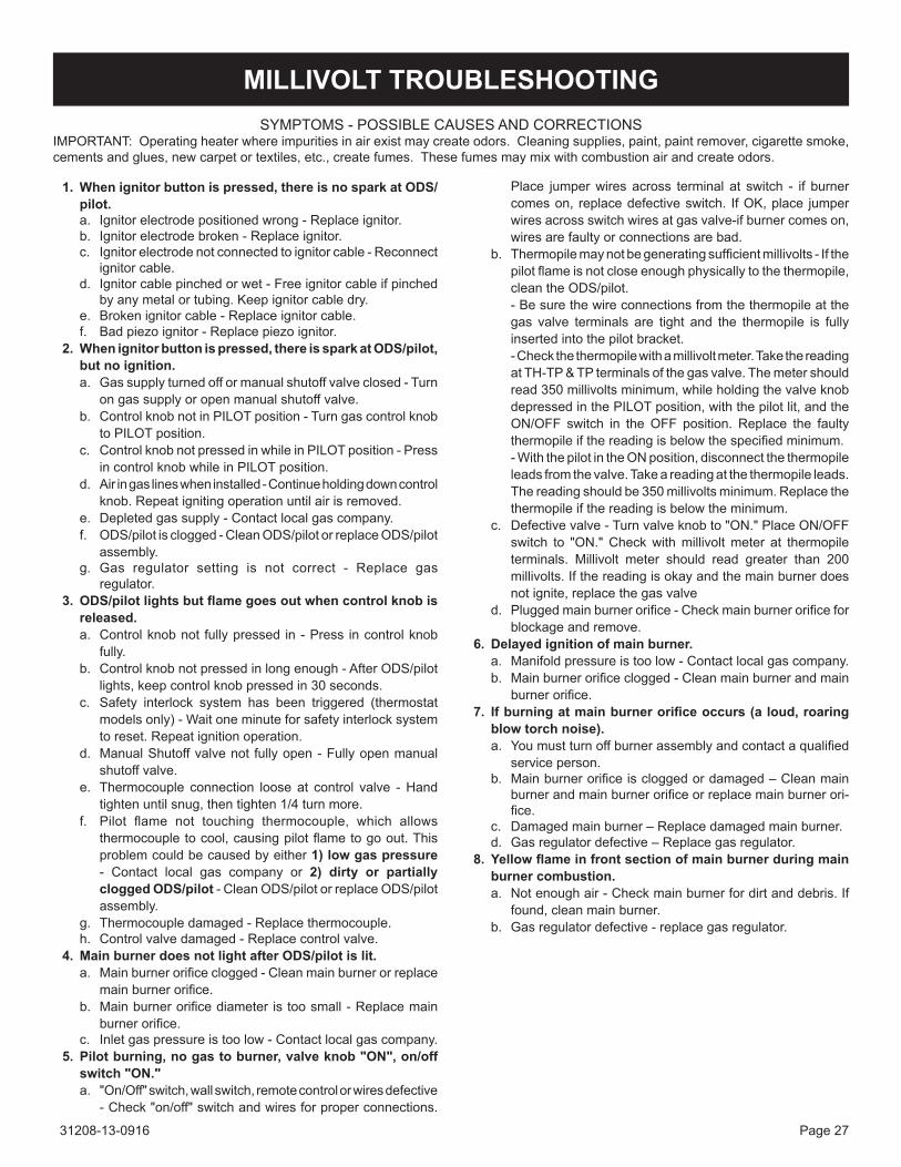
sYMPtoMs - PossiBLe caUses anD coRRectionsiMPoRtant:Operatingheaterwhereimpuritiesinairexistmaycreateodors.Cleaningsupplies,paint,paintremover,cigarettesmoke,cementsandglues,newcarpetortextiles,etc.,createfumes.Thesefumesmaymixwithcombustionairandcreateodors.
1. When ignitor button is pressed, there is no spark at oDS/pilot. a. ignitor electrode positioned wrong - Replace ignitor.b. Ignitorelectrodebroken-Replaceignitor.c. Ignitorelectrodenotconnectedtoignitorcable-Reconnect
ignitorcable.d. Ignitorcablepinchedorwet-Freeignitorcableifpinched
byanymetalortubing.Keepignitorcabledry.e. Brokenignitorcable-Replaceignitorcable.f. Bad piezo ignitor - Replace piezo ignitor.
2. When ignitor button is pressed, there is spark at oDS/pilot, but no ignition.a. gas supply turned off or manual shutoff valve closed - turn
on gas supply or open manual shutoff valve.b. ControlknobnotinPILOTposition-Turngascontrolknob
to PiLot position.c. ControlknobnotpressedinwhileinPILOTposition-Press
incontrolknobwhileinPILOTposition.d. air in gas lines when installed - continue holding down control
knob.Repeatignitingoperationuntilairisremoved.e. Depleted gas supply - contact local gas company.f. oDs/pilot is clogged - clean oDs/pilot or replace oDs/pilot
assembly.g. gas regulator setting is not correct - Replace gas
regulator. 3. oDS/pilot lights but flame goes out when control knob is
released.a. Controlknobnot fullypressed in-Press incontrolknob
fully.b. Controlknobnotpressedinlongenough-AfterODS/pilot
lights,keepcontrolknobpressedin30seconds.c. Safety interlock system has been triggered (thermostat
modelsonly)-Waitoneminuteforsafetyinterlocksystemto reset. Repeat ignition operation.
d. Manual shutoff valve not fully open - Fully open manual shutoff valve.
e. thermocouple connection loose at control valve - Hand tighten until snug, then tighten 1/4 turn more.
f. Pilot flame not touching thermocouple, which allowsthermocoupletocool,causingpilotflametogoout.Thisproblemcouldbecausedbyeither1) low gas pressure - contact local gas company or 2) dirty or partially clogged ODS/pilot - clean oDs/pilot or replace oDs/pilot assembly.
g. thermocouple damaged - Replace thermocouple.h. control valve damaged - Replace control valve.
4. Main burner does not light after ODS/pilot is lit.a. Mainburnerorificeclogged-Cleanmainburnerorreplace
mainburnerorifice.b. Mainburnerorificediameter istoosmall-Replacemain
burnerorifice.c. inlet gas pressure is too low - contact local gas company.
5. pilot burning, no gas to burner, valve knob "on", on/off switch "ON."a. "on/off" switch, wall switch, remote control or wires defective
-Check"on/off"switchandwiresforproperconnections.
Place jumperwires across terminal at switch - if burnercomes on, replace defective switch. if oK, place jumper wiresacrossswitchwiresatgasvalve-ifburnercomeson,wiresarefaultyorconnectionsarebad.
b. Thermopilemaynotbegeneratingsufficientmillivolts-Ifthepilotflameisnotcloseenoughphysicallytothethermopile,clean the oDs/pilot.
- Be sure the wire connections from the thermopile at the gas valve terminals are tight and the thermopile is fully insertedintothepilotbracket.
-Checkthethermopilewithamillivoltmeter.Takethereadingat tH-tP & tP terminals of the gas valve. the meter should read350millivoltsminimum,whileholdingthevalveknobdepressed in the PiLot position, with the pilot lit, and the on/oFF switch in the oFF position. Replace the faulty thermopileifthereadingisbelowthespecifiedminimum.
- With the pilot in the on position, disconnect the thermopile leadsfromthevalve.Takeareadingatthethermopileleads.Thereadingshouldbe350millivoltsminimum.Replacethethermopileifthereadingisbelowtheminimum.
c. Defectivevalve-Turnvalveknobto"ON."PlaceON/OFFswitch to "ON."Checkwithmillivoltmeter at thermopileterminals. Millivolt meter should read greater than 200 millivolts.Ifthereadingisokayandthemainburnerdoesnot ignite, replace the gas valve
d. Pluggedmainburnerorifice-Checkmainburnerorificeforblockageandremove.
6. Delayed ignition of main burner.a. Manifold pressure is too low - contact local gas company.b. Mainburnerorificeclogged-Cleanmainburnerandmain
burnerorifice. 7. If burning at main burner orifice occurs (a loud, roaring
blow torch noise).a. Youmustturnoffburnerassemblyandcontactaqualified
service person.b. Mainburnerorificeiscloggedordamaged–Cleanmain
burnerandmainburnerorificeorreplacemainburnerori-fice.
c. Damagedmainburner–Replacedamagedmainburner.d. Gasregulatordefective–Replacegasregulator.
8. Yellow flame in front section of main burner during main burner combustion.a. Notenoughair-Checkmainburnerfordirtanddebris.If
found,cleanmainburner.b. Gasregulatordefective-replacegasregulator.
MILLIVOLT TROUBLEShOOTING

31208-13-0916Page 28
9. Slight smoke or odor during initial operation.a. Residues from manufacturing processes and logs curing -
Problemwillstopafterafewhoursofoperation. 10. heater produces a whistling noise when main burner is
lit.a. Turningcontrolknob toHIpositionwhenmainburner is
cold-TurncontrolknobtoLOpositionandletwarmupfora minute.
b. Airingasline-Operatemainburneruntilairisremovedfromline.Havegaslinecheckedbylocalgascompany.
c. Airpassagewaysonheaterblocked-Observeminimuminstallation clearances (see page 9).
d. Dirtyorpartiallycloggedmainburnerorifice-Cleanmainburner and main burner orifice or replace main burnerorifice.
11. heater produces a clicking/ticking noise just after main burner is lit or shut off.a. Metal expanding while heating or contracting while cooling
- this is common with most heaters. if noise is excessive, contact service person.
12. heater produces unwanted odor.a. Heaterburningvaporsfrompaint,hairspray,glues,cleaners,
chemicals, new carpet, etc. - open window to ventilate room. stop using odor causing products while heater is operating.
b. Lowfuelsupply-Refillsupplytank.c. Gasleak-Locateandcorrectallleaks.
13. heater shuts off in use (ODS operates).a. Notenoughfreshairisavailable-Openwindowand/ordoor
for ventilation.b. Lowlinepressure-Contactlocalgascompany.c. oDs/pilot is partially clogged - clean oDs/pilot.
14. Gas odor even when control knob is in oFF position.a. Gasleak-Locateandcorrectallleaks.b. Controlvalvedefective-Replacecontrolvalve.
15. Gas odor during combustion.a. Foreignmatterbetween logsandmainburner - remove
foreign matter.b. Gasleak-Locateandcorrectallleaks.
16. Doors open on their own.a. casting not level. -Loosenfrontlevelingboltstoelevatefrontofcastingslightly
abovetherearofcasting.
MILLIVOLT TROUBLEShOOTING (continued)
31208-13-0916 Page 29
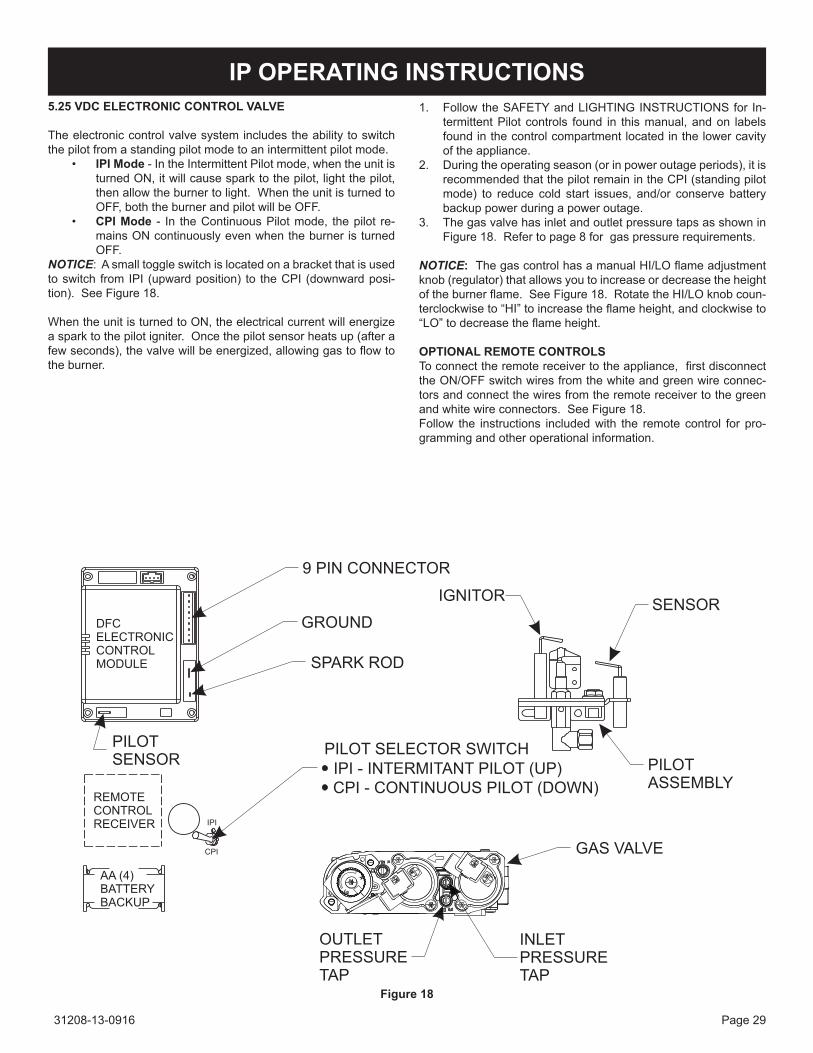
IP OPERATING INSTRUCTIONS5.25 VDC ELECTRONIC CONTROL VALVE
Theelectroniccontrolvalvesystemincludestheabilitytoswitchthe pilot from a standing pilot mode to an intermittent pilot mode.
• IPI Mode - in the intermittent Pilot mode, when the unit is turnedON,itwillcausesparktothepilot,lightthepilot,thenallowtheburnertolight.WhentheunitisturnedtoOFF,boththeburnerandpilotwillbeOFF.
• CPI Mode - in the continuous Pilot mode, the pilot re-mainsONcontinuouslyevenwhentheburneristurnedoFF.
NOTICE:Asmalltoggleswitchislocatedonabracketthatisusedto switch from iPi (upward position) to the cPi (downward posi-tion). see Figure 18.
When the unit is turned to on, the electrical current will energize asparktothepilotigniter.Oncethepilotsensorheatsup(afterafewseconds),thevalvewillbeenergized,allowinggastoflowtotheburner.
1. Follow the saFetY and LigHting instRUctions for in-termittentPilotcontrols found in thismanual,andon labelsfound in the control compartment located in the lower cavity of the appliance.
2. During the operating season (or in power outage periods), it is recommended that the pilot remain in the cPi (standing pilot mode) to reduce cold start issues, and/or conserve batterybackuppowerduringapoweroutage.
3. the gas valve has inlet and outlet pressure taps as shown in Figure18.Refertopage8forgaspressurerequirements.
NOTICE: ThegascontrolhasamanualHI/LOflameadjustmentknob(regulator)thatallowsyoutoincreaseordecreasetheheightoftheburnerflame.SeeFigure18.RotatetheHI/LOknobcoun-terclockwiseto“HI”toincreasetheflameheight,andclockwiseto“LO”todecreasetheflameheight.
OPTIONAL REMOTE CONTROLS Toconnecttheremotereceivertotheappliance,firstdisconnectthe on/oFF switch wires from the white and green wire connec-tors and connect the wires from the remote receiver to the green and white wire connectors. see Figure 18.Follow the instructions included with the remote control for pro-gramming and other operational information.
Figure 18

31208-13-0916Page 30
IP WIRING
If any of the original wire as suppliedwith this unitmust bereplaced, itmustbereplacedwithequivalentgaugeandtem-perature rated wire.
this appliance is only for use with the type of gas indicated on theratingplateandmaybeinstalledinanaftermarket,perma-nentlylocated,manufactured(mobile)homewherenotprohib-itedby local codes.This appliance is not convertible for usewith other gases.
CAUTIONDonotoperate theappliancewithpanel(s) removed,crackedor broken.Replacement of thepanel(s) shouldbedonebyalicensedorqualifiedserviceperson.
WARNINGimproper installation, adjustment, alteration, service or mainte-nance can cause property damage, personal injury or loss of life. Installationandservicemustbeperformedbyaqualifiedinstaller, service agency or the gas supplier.

31208-13-0916 Page 31
to tURn oFF gas to FiRePLace
1. STOP!Readthesafetyinformationabove.2. turn oFF electric power to the appliance.3. Removefrontsurroundpanelassemblyorbottomlouver if
included.4. Turngascockcounterclockwise to“On”position.5. Wait ten minutes to clear out any gas. then smell for gas,
includingnearthefloor.Ifyousmellgas,STOP!Follow“B”inthesafetyinformationaboveonthispage.Ifyoudonotsmellgas, go to the next step.
6. turn on electric power to the appliance.7. Findpilot-Followmetaltubefromgascontrol.Thepilot is
behindtheburnerontherightside.8. Turnmainflame toon. If thepilotdoesnot lightwithin60
seconds, stop and go to step 5.
9. Refer to remote control instructions for detailed information, control features, and operation. note: there is a cPi/iPi switch behindtherightsidepanelthatallowsforacontinuousstandingpilot mode or an intermittent pilot mode. see appliance manual forlocationofthisswitch.Ifthepilotorburnerdoesnotstaylit (in the standing pilot mode), stop and immediately call a qualifiedservicetechnicianorgassupplier.
10. Iftheburnerorpilotdoesnotoperateproperlyafterseveraltries,turnthegascockclockwise to“OFF”andcallyour service technician or gas supplier.
11. Replacethefrontsurroundassemblyorclosebottomlouverassembly.
12. Operation of the gas valve is controlled by a manual on/off switch or a hand held remote control. Refer to remote instructions for detailed operation information.
FoR YoUR saFetY ReaD BeFoRe LigHtingWaRning:Ifyoudonotfollowtheseinstructionsexactly,afireorexplosionmayresult
causing property damage, personal injury or loss of life.
A.Thisappliancehasapilotwhichmustbelightedbyhand.Whenlighting the pilot, follow these instructions exactly.
B. Before lighting smell all around the appliance area for gas. Be suretosmellnexttothefloorbecausesomegasisheavierthanairandwillsettleonthefloor.
What to Do if You smell gas• Donottrytolightanyappliance.• Donottouchanyelectricalswitch;• Donotuseanyphoneinyourbuilding.• Immediatelycallyourgassupplierfromaneighbor'sphone.
Followthegassupplier'sinstructions.• Ifyoucannotreachyourgassupplier,callthefiredepart-
ment.
C.Useonlyyourhandtopushinorturnthegascontrolknob.Neverusetools.Iftheknobwillnotpushinorturnbyhand,don'ttrytorepairit;callaqualifiedservicetechnician.Forceorattemptedrepairmayresultinafireorexplosion.
D.Donotusethisapplianceifanyparthasbeenunderwater.Immediatelycallaqualifiedservicetechniciantoinspecttheappliance and to replace any part of the control system and anygascontrolwhichhasbeenunderwater.
LigHting instRUctions
1. set ReMote/oFF/on switch to oFF.2. Turnoffallelectricpowertotheapplianceifserviceistobe
performed(ifapplicable).3. Lowerbottomlouverassembly.
4. Pushingascontrolknobslightlyandturnclockwise to "oFF." Do not force.
5. Closebottomlouverassembly.
IP LIGhTING INSTRUCTIONS
GAS CoCK

31208-13-0916Page 32
IP TROUBLEShOOTINGBrief Description of the ComponentsThegasvalveisequippedwithamanualHI/LOknobtoallowformanual modulation of the gas outlet pressure. the manual Hi/Lo knob can be replaced by an EmpireComfort SystemsVariableRemote Kit.
WARNINGThis appliance is equipped for Natural or Propane gas. Field conversion is not permitted.
the Digital Fireplace control (DFc) is an automatic gas ignition systembasedonasinglemicrocontrollercore.Thiscontrolman-agesall functionsrelatedto ignition,flamesensingandsupervi-sion for atmospheric applications. TheDFCcanbesettoprovidecontinuousorintermittentignitioncontrolsequencesandflamemonitoringwithsafetyshutdownincase of failure.the DFc is set up as a stand alone (ac powered system with batterybackup.SeeLightingInstructionsonpage24andWiringDiagram on page 23.
TroubleshootingBefore proceedingwith the procedures in the following trouble-shooting table, verify that the power supply (AC/DCadapter) ispresentandthatthebatteriesinsidethereceiverand/oroptionalbatterypackarefreshandinstalledwithcorrectpolarity.Makesureall theconnectionsbetween thewireharnessesandsystem components are proper and positive.Verify that the static inlet pressure meets the manufacturer’s rec-ommended inlet pressure. if necessary adjust the line pressure regulator.Iftherecommendedactionsforthefollowingtroubleshootingchartdonothelptoaddresstheproblemconsiderreplacingwiringhar-nesses.
WARNINGAny actions performed on the gas valve must be performed in accordance with this instruction manual. likewise, any actions performed on the DFC or other system components must be done in accordance with the individual component instructions. Replacement of components must be performed in accor-dance with this instructions manual.

31208-13-0916 Page 33
IP TROUBLEShOOTING

31208-13-0916Page 34
IP TROUBLEShOOTING

31208-13-0916 Page 35
Figure19showsacorrectmainburnerflamepattern.Figure20showsanincorrectmainburnerflamepattern.
Ifmainburnerflamepatternisincorrect,asshowninFigure22:• SeeTroubleshooting,pages20and21formillivoltmodelsand
pages 25 - 27 for iP models.
Correct Main Burner Flame will be yellow in ColorFigure 19
Incorrect Main Burner Flame will be Blue in ColorFigure 20
Cleaning and Maintenance / Main Burner
WARNINGTurnoffheaterandletcoolbeforecleaning.
Afteruse,cleaningofthemainburnermayberequiredfortheproperflame.Themainburnermaybecleanedbyapplyingairpressuretotheportsonthemainburner.Cleaning the log Set and Firebox
CAUTIONDo not handle these logs with your bare hands. Always wear gloves to prevent skin irritation.
During the annual inspection and maintenance appointment, the service person should clean dust, lint, and any light accumulation fromthelogsandthefireboxarea.Anextra-softbrushshouldbeusedonthelogsandburnerastheyareextremelyfragile;avacuumcleanermaybeusedonthefirebox.Ifatanytimethelogscannotberemovedorinstalledwithoutforcing,thecausemustbefound.Thelogsmustneverbeforced.
CAUTIONTheceramiclogsaredurablewhenhandledandinstalledproperly.However, theyaredelicateandmaybedamagedeasily ifnothandled with care. Handling damage to the ceramic logs is not coveredbywarranty.
Do not HanDLe Logs WHiLe tHeY aRe Hot. aLLoW PLentY oF tiMe FoR tHe aPPLiance to cooL coMPLeteLY BeFoRe HanDLing.
PLEASE NOTEIt is normal for appliances fabricated of steel to give off some expansion and/or contraction noises during the start up or cool down cycle. Similar noises are found with your furnace heat exchanger or car engine.
MAIN BURNER FLAME ChARACTERISTICS

31208-13-0916Page 36
IMPORTANT: Turn off gas before servicing appliance. It isrecommended that a qualified service technician perform thesecheck-upsatthebeginningofeachheatingseason.• CleanBurnerandControlCompartment Keepthecontrolcompartment,logsandburnerareasurroundingthelogscleanbyvacuumingorbrushingatleasttwiceayear.
Cleaning Procedure1. turn off pilot light at gas valve.2. Remove screen front. (two 10 x 1/2" screws)3. Vacuumburnercompartmentespeciallyaroundorifice/primary
air openings. 4. Replace screen front. (two 10 x 1/2" screws)5. ignite pilot. (see Lighting instructions, pages 14 and 24)6. Operatethemainburnerandvisuallychecktomakesurethe
flamepatternappearssimilartothepictorialillustrationshownforpropermainburnerflamepattern,Figure19.Ifitappearsabnormalcallaserviceperson.
Verify proper operation after servicing.
MAINTENANCE
Figure 21

31208-13-0916 Page 37
PLEASENOTE:Whenorderingparts,itisveryimportantthatpartnumberanddescriptionofpartcoincide.
PARTS LIST - VFD10CC(30,70)
USEONLYMANUFACTURER'SREPLACEMENTPARTS.USEOFANYOTHERPARTSCOULDCAUSEINjURYORDEATH.
InDEX NO.
PART NO. DESCRIPTION
VFD10CC30(B,F,M)(N,P)1 31093 BURneR sHieLD (LPg onLY)2 24043 FiReBoX BRace (2 ReQUiReD)3 29534 FiReBoX toP4 29528 FiReBoX WaLLs5 29865 scReen FRaMe asseMBLY6 17235 BRacKet, Log LocatoR7 R11207 BURneR, tUBe8a P208 oRiFice - nat8b P193 oRiFice - LPg9 R7572 jAMBNUT10 31103 BURneR Base11a R3624 PiLot asseMBLY - nat11b R3623 PiLot asseMBLY - LPg12 21590 PiLot BRacKet13 P212 Fitting, oRiFice14 29526 VaLVe BRacKet15 R2423 connectoR, MaLe 5/1616 23496 tUBing asseMBLY, PiLot - LPg
17 23492 tUBing asseMBLY, RegULatoR to PiLot - nat
18 R7063 PiLot RegULatoR (nat onLY)
19 23491 tUBing asseMBLY, VaLVe to RegULatoR - nat
20 29524 tUBing asseMBLY, inLet21a R3626 VaLVe - nat21b R3625 VaLVe - LPg22 29523 FiReBoX BottoM23 29769 VaLVe coVeR asseMBLY24 R9760 PieZo igniteR26 29533 ReaR coVeR
InDEX NO.
PART NO. DESCRIPTION
VFD10CC70(B,F,M)(N,P)1 31093 BURneR sHieLD (LPg onLY)2 24043 FiReBoX BRace (2 ReQUiReD)3 29534 FiReBoX toP4 29528 FiReBoX WaLLs5 29865 scReen FRaMe asseMBLY6 17235 BRacKet, Log LocatoR7 R11207 BURneR, tUBe
8a P208 oRiFice - nat8b P193 oRiFice - LPg9 R7572 jAMBNUT10 31103 BURneR Base11a R11328 PiLot asseMBLY - nat11b R11327 PiLot asseMBLY - LPg12 31096 PiLot BRacKet13 P212 Fitting, oRiFice14 29770 VaLVe BRacKet15 R2423 connectoR, MaLe 5/1616 31098 tUBing asseMBLY, PiLot - LPg
17 31099 tUBing asseMBLY, RegULatoR to PiLot - nat
18 R7063 PiLot RegULatoR (nat onLY)
19 29543 tUBing asseMBLY, VaLVe to RegULatoR - nat
20 29541 tUBing asseMBLY, inLet21a R11125 VaLVe - nat21b R11126 VaLVe - LPg22 29523 FiReBoX BottoM23 29769 VaLVe coVeR asseMBLY25 31092 PiLot sHieLD26 29533 ReaR coVeR27 R7591 FLeX Line WitH sHUt oFF28 R11122 BatteRY HoLDeR29 R11123 WiRe HaRness, PRoFLaMe DFc30 R11127 contRoL BoaRD, PRoFLaMe DFc31 R11128 PoWeR aDaPtoR, 7.0 VDcn/s R11332 WiRe, sensoR - 24"n/s R11333 WiRe, igniteR - 24"
n/s - not sHoWn

31208-13-0916Page 38
PARTS VIEW - VFD10CC(30,70)
1
2
3
4
26
5
6
7
8
9
10
11
11
12
12
13
14 14
15
17
1616
17
18
1819
192020
21
21
22
2324
25
29
27
31
28
30

31208-13-0916 Page 39
USEONLYMANUFACTURER'SREPLACEMENTPARTS.USEOFANYOTHERPARTSCOULDCAUSEINjURYORDEATH.
PLEASENOTE:Whenorderingparts,itisveryimportantthatpartnumberanddescriptionofpartcoincide.
PARTS LIST - VFD20CC(30,70)
InDEX NO. PART NO. DESCRIPTION
VFD20CC30(B,F,M)(N,P)1 29531 oUtLet BaFFLe2 24043 FiReBoX BRace (2 ReQUiReD)3 29530 FiReBoX toP4 29528 FiReBoX WaLLs5 29865 scReen FRaMe asseMBLY6 17235 BRacKet, Log LocatoR7 R11206 BURneR, tUBe8a P316 oRiFice - nat8b P289 oRiFice - LPg9 R7572 jAMBNUT10 31103 BURneR Base11a R3624 PiLot asseMBLY - nat11b R3623 PiLot asseMBLY - LPg12 21590 PiLot BRacKet13 P212 Fitting, oRiFice14 29526 VaLVe BRacKet15 R2423 connectoR, MaLe 5/1616 23496 tUBing asseMBLY, PiLot - LPg
17 23492 tUBing asseMBLY, RegULatoR to PiLot - nat
18 R7063 PiLot RegULatoR (nat onLY)
19 23491 tUBing asseMBLY, VaLVe to RegULatoR - nat
20 29524 tUBing asseMBLY, inLet21a R3626 VaLVe - nat21b R3625 VaLVe - LPg22 29523 FiReBoX BottoM23 29769 VaLVe coVeR asseMBLY24 R9760 PieZo igniteR25 29533 ReaR coVeR
InDEX NO. PART NO. DESCRIPTION
VFD20CC70(B,F,M)(N,P)1 29531 oUtLet BaFFLe2 24043 FiReBoX BRace (2 ReQUiReD)3 29530 FiReBoX toP4 29528 FiReBoX WaLLs5 29865 scReen FRaMe asseMBLY6 17235 BRacKet, Log LocatoR7 R11206 BURneR, tUBe8a P316 oRiFice - nat8b P289 oRiFice - LPg9 R7572 jAMBNUT10 31103 BURneR Base11a R11328 PiLot asseMBLY - nat11b R11327 PiLot asseMBLY - LPg12 29535 PiLot BRacKet13 P212 Fitting, oRiFice14 29770 VaLVe BRacKet15 R2423 connectoR, MaLe 5/1616 29542 tUBing asseMBLY, PiLot - LPg
17 29544 tUBing asseMBLY, RegULatoR to PiLot - nat
18 R7063 PiLot RegULatoR (nat onLY)
19 29543 tUBing asseMBLY, VaLVe to RegULatoR - nat
20 29541 tUBing asseMBLY, inLet21a R11125 VaLVe - nat21b R11126 VaLVe - LPg22 29523 FiReBoX BottoM23 29769 VaLVe coVeR asseMBLY27 R7591 FLeX Line WitH sHUt oFF28 R11122 BatteRY HoLDeR29 R11123 WiRe HaRness, PRoFLaMe DFc30 R11127 contRoL BoaRD, PRoFLaMe DFc31 R11128 PoWeR aDaPtoR, 7.0 VDc
n/s R11332 WiRe, sensoR - 24"n/s R11333 WiRe, igniteR - 24"n/s R7591 FLeX Line WitH sHUt oFF
n/s - not sHoWn

31208-13-0916Page 40
PARTS VIEW - VFD20CC(30,70)
1
2
3
4
25
5
6
7
8
9
10
1111
12 1213
14 14
15
17
16 1617
18 18
19 1920
20
21
21
22
2324
29
27
31
28
30

31208-13-0916 Page 41
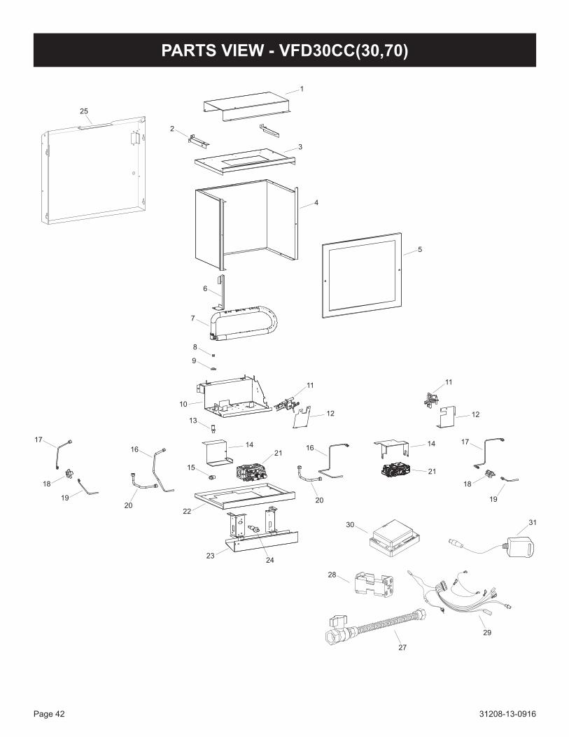
PARTS LIST - VFD30CC(30,70)
InDEX NO. PART NO. DESCRIPTION
VFD30CC30(B,F,M,S,W)(N,P)1 15484 oUtLet BaFFLe2 24043 FiReBoX BRace (2 ReQUiReD)3 23938 FiReBoX toP4 29529 FiReBoX WaLLs5 15567 scReen FRaMe asseMBLY6 17235 BRacKet, Log LocatoR7 R11209 BURneR, tUBe8a P286 oRiFice - nat8b P293 oRiFice - LPg9 R7572 jAMBNUT10 29521 BURneR Base11a R3624 PiLot asseMBLY - nat11b R3623 PiLot asseMBLY - LPg12 21590 PiLot BRacKet13 P212 Fitting, oRiFice14 29526 VaLVe BRacKet15 R2423 connectoR, MaLe 5/1616 23496 tUBing asseMBLY, PiLot - LPg
17 23492 tUBing asseMBLY, RegULatoR to PiLot - nat
18 R7063 PiLot RegULatoR (nat onLY)
19 23491 tUBing asseMBLY, VaLVe to RegULatoR - nat
20 29525 tUBing asseMBLY, inLet21a R3626 VaLVe - nat21b R3625 VaLVe - LPg22 29527 FiReBoX BottoM23 15516 VaLVe coVeR asseMBLY24 R9760 PieZo igniteR25 30676 ReaR coVeR
InDEX NO. PART NO. DESCRIPTION
VFD30CC70(B,F,M,S,W)(N,P)1 15484 oUtLet BaFFLe2 24043 FiReBoX BRace (2 ReQUiReD)3 23938 FiReBoX toP4 29529 FiReBoX WaLLs5 15567 scReen FRaMe asseMBLY6 17235 BRacKet, Log LocatoR7 R11209 BURneR, tUBe
8a P286 oRiFice - nat8b P293 oRiFice - LPg9 R7572 jAMBNUT
10 29521 BURneR Base11a R11328 PiLot asseMBLY - nat11b R11327 PiLot asseMBLY - LPg12 29535 PiLot BRacKet13 P212 Fitting, oRiFice14 29770 VaLVe BRacKet15 R2423 connectoR, MaLe 5/1616 29536 tUBing asseMBLY, PiLot - LPg
17 29538 tUBing asseMBLY, RegULatoR to PiLot - nat
18 R7063 PiLot RegULatoR (nat onLY)
19 29537 tUBing asseMBLY, VaLVe to RegULatoR - nat
20 29539 tUBing asseMBLY, inLet21a R11125 VaLVe - nat21b R11126 VaLVe - LPg22 29527 FiReBoX BottoM23 15516 VaLVe coVeR asseMBLY27 R7591 FLeX Line WitH sHUt oFF28 R11122 BatteRY HoLDeR29 R11123 WiRe HaRness, PRoFLaMe DFc30 R11127 contRoL BoaRD, PRoFLaMe DFc31 R11128 PoWeR aDaPtoR, 7.0 VDcn/s R11332 WiRe, sensoR - 24"n/s R11333 WiRe, igniteR - 24"n/s R7591 FLeX Line WitH sHUt oFF
n/s - not sHoWn
PLEASENOTE:Whenorderingparts,itisveryimportantthatpartnumberanddescriptionofpartcoincide.
USEONLYMANUFACTURER'SREPLACEMENTPARTS.USEOFANYOTHERPARTSCOULDCAUSEINjURYORDEATH.
31208-13-0916Page 42
PARTS VIEW - VFD30CC(30,70)
1
2
3
4
25
5
6
7
8
9
10
1111
12 1213
14 14
15
17
16 1617
18 18
19 1920
20
21
21
22
2324
29
27
31
28
30

31208-13-0916 Page 43
CASTING PARTS LIST - VFD(10,20,30)CC(30,70)
USE ONLy MANUFACTURER'S REPLACEMENT PARTS. USE OF ANy OThER PARTS COULD CAUSE INjURy OR DEATh.
PLEASENOTE:Whenorderingparts,itisveryimportantthatpartnumberanddescriptionofpartcoincide.
InDEX NO.
PART NUMBERDESCRIPTION
VFD10 VFD20 VFD30COMMON PARTS
11 R9671 R9671 R9671 inseRt taB (4 ReQUiReD)
ns n/a n/a R9669 Hinge Pin (4 ReQUiReD)
ns R9924 R9924 R9924 BoLt, 1/4-20 X 3/4” (12 ReQUiReD)
ns R9670 R9670 n/a BoLt, 1/4-20 X 1/2” (20 ReQUiReD)
ns R9829 R9829 R9829 BoLt, 1/4-20 X 2” (4 ReQUiReD)
MATTE BlACK1 R11308 R11308 R11308 casting, inseRt Vent
2 n/a n/a R9538 toP inseRt - RigHt
3 n/a n/a R9537 toP inseRt - LeFt
4 R11307 R11307 R9536 casting toP
5 R11309 R11309 R9666 casting FRont
6 R11306 R11306 R9535 casting siDe - RigHt
7 R11305 R11305 R9534 casting siDe - LeFt
8 n/a n/a R9668 casting DooR - RigHt
9 n/a n/a R9667 casting DooR - LeFt
10 24042 24042 24042 FiReBoX sUPPoRt BRacKet (2 ReQUiReD)
12 R11304 R11304 R9533 casting Leg B
13 R11303 R11303 R9532 casting Leg a
MATTE PEWTER1 n/a n/a R11322 casting, inseRt Vent
2 n/a n/a R9554 toP inseRt - RigHt
3 n/a n/a R9553 toP inseRt - LeFt
4 n/a n/a R9552 casting toP
5 n/a n/a R9693 casting FRont
6 n/a n/a R9551 casting siDe - RigHt
7 n/a n/a R9550 casting siDe - LeFt
8 n/a n/a R9695 casting DooR - RigHt
9 n/a n/a R9694 casting DooR - LeFt
10 n/a n/a 24042 FiReBoX sUPPoRt BRacKet (2 ReQUiReD)
12 n/a n/a R9549 casting Leg B
13 n/a n/a R9548 casting Leg a
poRCElAIn BlACK1 R11315 R11315 R11308 casting, inseRt Vent
2 n/a n/a R9570 toP inseRt - RigHt
3 n/a n/a R9569 toP inseRt - LeFt
4 R11314 R11314 R9568 casting toP
5 R11316 R11316 R9681 casting FRont
6 R11313 R11313 R9567 casting siDe - RigHt
7 R11312 R11312 R9566 casting siDe - LeFt
8 n/a n/a R9683 casting DooR - RigHt
9 n/a n/a R9682 casting DooR - LeFt
10 24042 24042 24042 FiReBoX sUPPoRt BRacKet (2 ReQUiReD)
12 R11311 R11311 R9565 casting Leg B
13 R11310 R11310 R9564 casting Leg a
PORCELAIN SAND1 n/a n/a R11353 casting, inseRt Vent
2 n/a n/a R9586 toP inseRt - RigHt
3 n/a n/a R9585 toP inseRt - LeFt
4 n/a n/a R9584 casting toP
5 n/a n/a R9700 casting FRont
6 n/a n/a R9583 casting siDe - RigHt
7 n/a n/a R9582 casting siDe - LeFt
8 n/a n/a R9702 casting DooR - RigHt
9 n/a n/a R9701 casting DooR - LeFt
10 n/a n/a 24042 FiReBoX sUPPoRt BRacKet (2 ReQUiReD)
12 n/a n/a R9581 casting Leg B
13 n/a n/a R9580 casting Leg a
PORCELAIN MAhOGANy1 R11322 R11322 R11322 casting, inseRt Vent
2 n/a n/a R9602 toP inseRt - RigHt
3 n/a n/a R9601 toP inseRt - LeFt
4 R11321 R11321 R9600 casting toP
5 R11323 R11323 R9707 casting FRont
6 R11320 R11320 R9599 casting siDe - RigHt
7 R11319 R11319 R9598 casting siDe - LeFt
8 n/a n/a R9709 casting DooR - RigHt
9 n/a n/a R9708 casting DooR - LeFt
10 24042 24042 24042 FiReBoX sUPPoRt BRacKet (2 ReQUiReD)
12 R11318 R11318 R9597 casting Leg B
13 R11317 R11317 R9596 casting Leg a
ns - not sHoWn
InDEX NO.
PART NUMBERDESCRIPTION
VFD10 VFD20 VFD30

31208-13-0916Page 44
2
3
9
4
5
6
7
8
10
10
1
11
11
11
11
13
12
12
13
CASTING PARTS VIEW - VFD(10,20,30)CC(30,70)

31208-13-0916 Page 45
to order Parts Under Warranty, please contact your local empire dealer. see the dealer locator at www.empirecomfort.com.Toprovidewarrantyservice,yourdealerwillneedyournameandaddress,purchasedateandserialnumber,andthenatureoftheproblemwiththeunit.ToOrderPartsAftertheWarrantyPeriod,pleasecontactyourdealeroroneoftheMasterPartsDistributorslistedbelow.Thislistchangesfromtimetotime.Forthecurrentlist,pleaseclickontheMasterPartsbuttonatwww.empirecomfort.com.Pleasenote:MasterPartsDistributorsareindependentbusinessesthatstockthemostcommonlyorderedOriginalEquip-mentrepairpartsforHeaters,Grills,andFireplacesmanufacturedbyEmpireComfortSystemsInc.
MASTER PARTS DISTRIBUTOR LIST
parts not Under WarrantyPartscanbeorderedthroughyourServicePerson,Dealer,oraMasterPartsDistributor.SeethispagefortheMasterPartsDistribu-torslist.Forbestresults,theservice person or dealershouldorderpartsthroughthedistributor.Partscanbeshippeddirectlytotheservice person/dealer.Warranty partsWarrantypartswillneedaproofofpurchaseandcanbeorderedbyyourServicePersonorDealer.Proofofpurchaseisrequired for warranty parts.AllpartslistedinthePartsListhaveaPartNumber.Whenorderingparts,firstobtaintheModelNumberandSerialNumberfromthenameplateonyourequipment.ThendeterminethePartNumber(nottheIndexNumber)andtheDescriptionofeachpartfromthefol-lowing illustration and part list. Be sure to give all this information . . .
ApplianceModelNumber Part Description
ApplianceSerialNumber PartNumber
type of gas (Propane or natural)
Donotorderbolts,screws,washersornuts.Theyarestandardhardwareitemsandcanbepurchasedatanylocalhardwarestore.Shipmentscontingentuponstrikes,firesandallcausesbeyondourcontrol.
hOW TO ORDER REPAIR PARTS
Dey Distributing1401WillowLakeBoulevardVadnais Heights, Mn 55101
Phone: 651-490-9191Toll Free: 800-397-1339Website:www.deydistributing.comParts: heater, hearth and Grills
Victor Division of F. W. Webb Company200 Locust streetHartford, ct 06114
Phone: 860-722-2433Toll Free: 800-243-9360Fax: 860-293-0479Toll Free Fax: 800-274-2004Websites: www.fwwebb.com&www.victormfg.comParts: heater, hearth and Grills
East Coast Energy products10 east Route 36WestLongBranch,Nj07764
Phone: 732-870-8809Toll Free: 800-755-8809Fax: 732-870-8811Website: www.eastcoastenergy.comParts: heater, hearth and Grills

31208-13-0916Page 46
ACCESSORy SIDE ShELVES INSTALLATION INSTRUCTIONSInstalling Accessory Side Shelves:1. Remove cast iron or stone inlay inserts from casting top and
carefully set them aside.2. Remove cast iron top from stove and place upside down on a
flat,softsmoothsurfacetoavoiddamage.3. Removefour¼-20hexheadboltsfromtheouteredgesofcast
iron top.4. Place left and right side shelves in place shown in Figure 22.5. Replacefour¼-20hexheadbolts toattachsideshelvesto
castirontop,besureshelfistighttocastingtopbeforefullytighteningbolts.
6. Removeeight¼-20hexheadboltsfromsideshelves.7. Replace cast iron top on unit.
8. attach side shelf supports one at a time, using two ¼-20 hex headboltspersupport,slidingsupportflushtocastingbeforefullytighteningboltsasshowninFigure22.
9. Replace cast iron or stone inlay inserts into casting top.
NOTICE: Be sure to remove side shelf supports prior to removing cast iron top to eliminate potential scratching or chipping to the cast iron sides.NOTICE: Due to inherent properties of the casting process, non-combustibleshimsmaybe required to levelaccessorysideshelves to the casting top. these shims are provided in the form ofwasherstobeusedoneithersideofthebolts.SeeFigure22.Ifaccessoryshelfanglesdownward,towardthefloor,washer(s)willneedtobeaddedtothecentersideofthebolt.Conversely,iftheaccessory side shelf angles upward, toward the ceiling, washer(s) willneedtobeaddedtotheoutsideofthetopcastingsideofthebolt.SeeFigure25.
Figure 22
Figure 23
Installation of optional Stone Inlay1. Remove left cast iron insert and right cast iron insert from casting
top.
2. insert left stone inlay and right stone inlay into casting top.3. installation of stone inlay is completed.
OPTIONAL STONE INLAy INSTALLATION INSTRUCTIONS
Figure 24
Figure 25
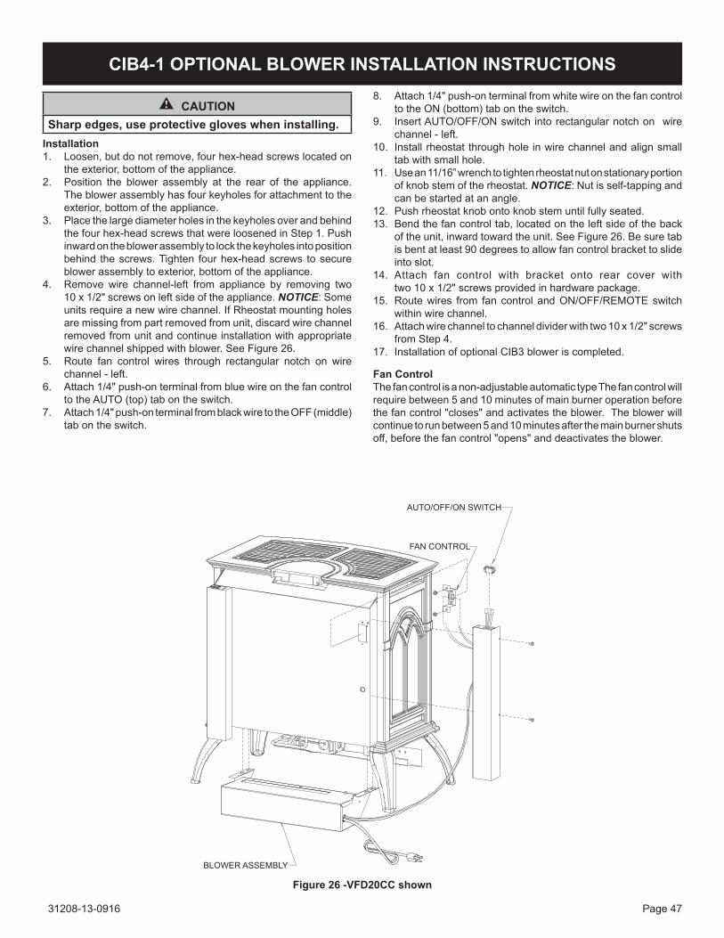
31208-13-0916 Page 47
CIB4-1 OPTIONAL BLOWER INSTALLATION INSTRUCTIONS
CAUTIONSharp edges, use protective gloves when installing.
Installation1. Loosen,butdonotremove,fourhex-headscrewslocatedon
theexterior,bottomoftheappliance.2. Position the blower assembly at the rear of the appliance.
Theblowerassemblyhasfourkeyholesforattachmenttotheexterior,bottomoftheappliance.
3. Placethelargediameterholesinthekeyholesoverandbehindthe four hex-head screws that were loosened in step 1. Push inwardontheblowerassemblytolockthekeyholesintopositionbehind thescrews.Tighten fourhex-headscrews tosecureblowerassemblytoexterior,bottomoftheappliance.
4. Remove wire channel-left from appliance by removing two 10 x 1/2" screws on left side of the appliance. NOTICE: some unitsrequireanewwirechannel.IfRheostatmountingholesare missing from part removed from unit, discard wire channel removed from unit and continue installation with appropriate wirechannelshippedwithblower.SeeFigure26.
5. Route fan control wires through rectangular notch on wire channel - left.
6. Attach1/4"push-onterminalfrombluewireonthefancontroltotheAUTO(top)tabontheswitch.
7. Attach1/4"push-onterminalfromblackwiretotheOFF(middle)tabontheswitch.
Figure 26 -VFD20CC shown
8. attach 1/4" push-on terminal from white wire on the fan control totheON(bottom)tabontheswitch.
9. insert aUto/oFF/on switch into rectangular notch on wire channel - left.
10. install rheostat through hole in wire channel and align small tabwithsmallhole.
11. Use an 11/16” wrench to tighten rheostat nut on stationary portion ofknobstemoftherheostat.NOTICE: nut is self-tapping and canbestartedatanangle.
12. Pushrheostatknobontoknobstemuntilfullyseated.13. Bendthefancontroltab,locatedontheleftsideoftheback
oftheunit,inwardtowardtheunit.SeeFigure26.Besuretabisbentatleast90degreestoallowfancontrolbrackettoslideinto slot.
14. Attach fan control with bracket onto rear cover with two10x1/2"screwsprovidedinhardwarepackage.
15. Route wires from fan control and on/oFF/ReMote switch within wire channel.
16. attach wire channel to channel divider with two 10 x 1/2" screws from step 4.
17. InstallationofoptionalCIB3bloweriscompleted.
Fan ControlThefancontrolisanon-adjustableautomatictypeThefancontrolwillrequirebetween5and10minutesofmainburneroperationbeforethefancontrol"closes"andactivatestheblower.Theblowerwillcontinuetorunbetween5and10minutesafterthemainburnershutsoff,beforethefancontrol"opens"anddeactivatestheblower.
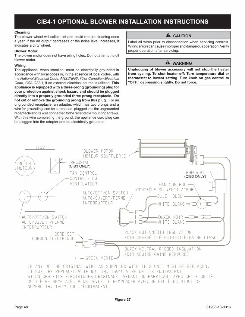
31208-13-0916Page 48
CleaningTheblowerwheelwillcollectlintandcouldrequirecleaningoncea year. if the air output decreases or the noise level increases, it indicates a dirty wheel. Blower MotorTheblowermotordoesnothaveoilingholes.Donotattempttooilblowermotor.WiringThe appliance,when installed,must be electrically grounded inaccordancewithlocalcodesor,intheabsenceoflocalcodes,withthe National Electrical Code, ANSI/NFPA 70 or Canadian Electrical Code, CSA C22.1, if an external electrical source is utilized. This appliance is equipped with a three-prong (grounding) plug for your protection against shock hazard and should be plugged directly into a properly grounded three-prong receptacle. Do not cut or remove the grounding prong from this plug. For an ungrounded receptacle, an adapter, which has two prongs and a wireforgrounding,canbepurchased,pluggedintotheungroundedreceptacle and its wire connected to the receptacle mounting screws. With this wire completing the ground, the appliance cord plug can bepluggedintotheadapterandbeelectricallygrounded.
CIB4-1 OPTIONAL BLOWER INSTALLATION INSTRUCTIONS
Figure 27
CAUTIONLabelallwiresprior todisconnectionwhenservicingcontrols.Wiring errors can cause improper and dangerous operation. Verify proper operation after servicing.
WARNINGUnplugging of blower accessory will not stop the heater from cycling. To shut heater off: Turn temperature dial or thermostat to lowest setting. Turn knob on gas control to "OFF," depressing slightly. Do not force.

31208-13-0916 Page 49
CIB3-1 OPTIONAL BLOWER INSTALLATION INSTRUCTIONS
CAUTIONSharp edges, use protective gloves when installing.
Installation1. Loosen,butdonotremove,fourhex-headscrewslocatedon
theexterior,bottomoftheappliance.2. Position the blower assembly at the rear of the appliance.
Theblowerassemblyhasfourkeyholesforattachmenttotheexterior,bottomoftheappliance.
3. Placethelargediameterholesinthekeyholesoverandbehindthe four hex-head screws that were loosened in step 1. Push inwardontheblowerassemblytolockthekeyholesintopositionbehind thescrews.Tighten fourhex-headscrews tosecureblowerassemblytoexterior,bottomoftheappliance.
4. Remove wire channel-left from appliance by removing 10 x 1/2" screws on left side of the appliance. Note: some unitsrequireanewwirechannel.IfRheostatmountingholesare missing from part removed from unit, discard wire channel removed from unit and continue installation with appropriate wirechannelshippedwithblower.SeeFigure28.
5. Route fan control wires through rectangular notch on wire channel - left.
6. Attach1/4"push-onterminalfrombluewireonthefancontroltotheAUTO(top)tabontheswitch.
7. Attach1/4"push-onterminalfromblackwiretotheOFF(middle)tabontheswitch.
8. attach 1/4" push-on terminal from white wire on the fan control totheON(bottom)tabontheswitch.
9. insert aUto/oFF/on switch into rectangular notch on wire channel - left.
10. install rheostat through hole in wire channel and align small tabwithsmallhole.
11. Use an 11/16” wrench to tighten rheostat nut on stationary portionofknobstemoftherheostat.Note: nut is self-tapping andcanbestartedatanangle.
12. Pushrheostatknobontoknobstemuntilfullyseated.13. Bendthefancontroltab,locatedontheleftsideoftheback
oftheunit,inwardtowardtheunit.SeeFigure28.Besuretabisbentatleast90degreestoallowfancontrolbrackettoslideinto slot.
14. Attach fan control with bracket onto rear cover with two 10x1/2"screwsprovidedinhardwarepackage.
15. Route wires from fan control and on/oFF/ReMote switch within wire channel.
16. attach wire channel to channel divider with two 10 x 1/2" screws from step 4.
17. InstallationofoptionalCIB3bloweriscompleted.
Figure 28 - DVP30CC Shown
DVP30cc shown
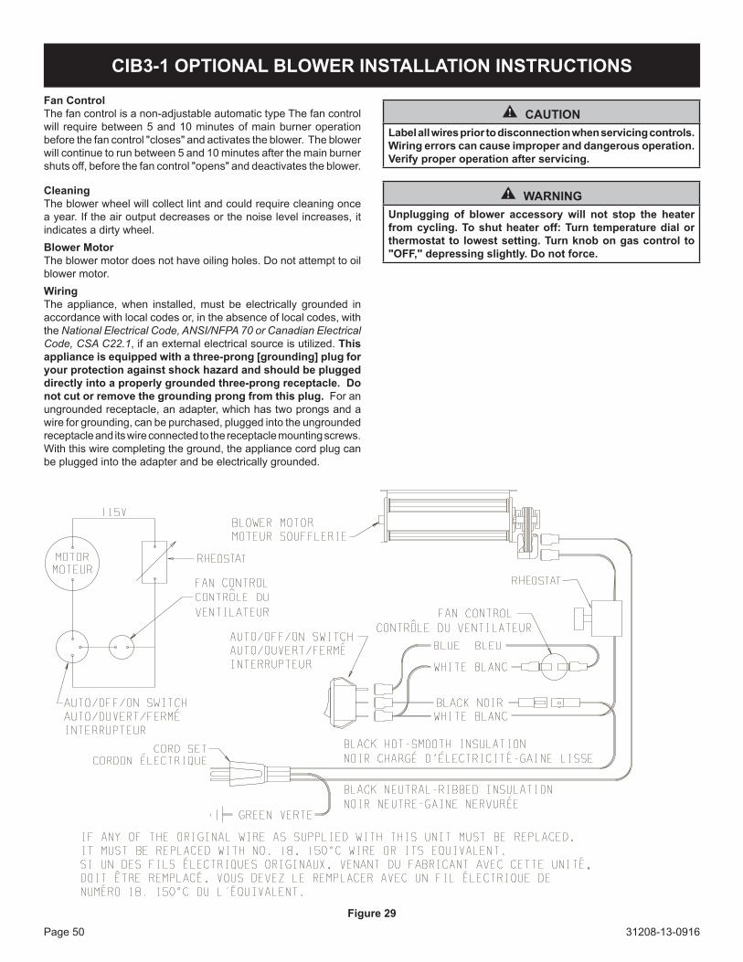
31208-13-0916Page 50
CIB3-1 OPTIONAL BLOWER INSTALLATION INSTRUCTIONS
Fan ControlThefancontrolisanon-adjustableautomatictypeThefancontrolwill requirebetween5and10minutesofmainburneroperationbeforethefancontrol"closes"andactivatestheblower.Theblowerwillcontinuetorunbetween5and10minutesafterthemainburnershutsoff,beforethefancontrol"opens"anddeactivatestheblower.
CleaningTheblowerwheelwillcollectlintandcouldrequirecleaningoncea year. if the air output decreases or the noise level increases, it indicates a dirty wheel. Blower MotorTheblowermotordoesnothaveoilingholes.Donotattempttooilblowermotor.WiringThe appliance,when installed,must be electrically grounded inaccordancewithlocalcodesor,intheabsenceoflocalcodes,withthe National Electrical Code, ANSI/NFPA 70 or Canadian Electrical Code, CSA C22.1, if an external electrical source is utilized. This appliance is equipped with a three-prong [grounding] plug for your protection against shock hazard and should be plugged directly into a properly grounded three-prong receptacle. Do not cut or remove the grounding prong from this plug. For an ungrounded receptacle, an adapter, which has two prongs and a wireforgrounding,canbepurchased,pluggedintotheungroundedreceptacle and its wire connected to the receptacle mounting screws. With this wire completing the ground, the appliance cord plug can bepluggedintotheadapterandbeelectricallygrounded.
Figure 29
CAUTIONLabel all wires prior to disconnection when servicing controls. Wiring errors can cause improper and dangerous operation. Verify proper operation after servicing.
WARNINGUnplugging of blower accessory will not stop the heater from cycling. To shut heater off: Turn temperature dial or thermostat to lowest setting. Turn knob on gas control to "OFF," depressing slightly. Do not force.
31208-13-0916 Page 51
WARRANTy
EmpireComfortSystemsInc.warrantiesthishearthproducttobefreefromdefectsatthetimeofpurchaseandfortheperiodsspeci-fiedbelow.Hearthproductsmustbeinstalledbyaqualifiedtechnicianandmustbemaintainedandoperatedsafely,inaccordancewiththeinstructionsintheowner’smanual.Thiswarrantyappliestotheoriginalpurchaseronlyandisnottransferable.Allwarrantyrepairsmustbeaccomplishedbyaqualifiedgasappliancetechnician.
Limited Lifetime Parts Warranty with a Five-Year Limited Labor Warranty – Combustion Chamber and Heat ExchangerIfthecombustionchamberorheatexchanger(seepartslist)failsbecauseofdefectiveworkmanshipormaterial,Empirewillrepairor replace at empire’s option. Withinfiveyearsfromthedateofpurchase,Empirewillpayreasonablelabortohavethedefectivepartrepairedorreplacedatempire’s option.
Limited Five-Year Parts & Labor Warranty – All Other Components (except Remote controls, thermostats, accessories and Replacement Parts) Shouldanypartfailbecauseofdefectiveworkmanshipormaterialwithinfiveyearsfromthedateofpurchase,Empirewillrepair or replace at empire’s option. Withinfiveyearsfromthedateofpurchase,EmpirewillpayreasonablelabortohavethatdefectrepairedatEmpire’soption.
Limited One-Year Parts Warranty – Remote Controls, Thermostats, Accessories, and Parts Shouldanyremotecontrol,thermostat,accessory,orotherpartfailbecauseofdefectiveworkmanshipwithinoneyearfromthe date of purchase, empire will repair or replace at empire’s option.
Duties Of The Owner Theappliancemustbeinstalledbyaqualifiedinstallerandoperatedinaccordancewiththeinstructionsfurnishedwiththeap-pliance. Abillofsale,cancelledcheck,orpaymentrecordshouldbekepttoverifypurchasedateandestablishwarrantyperiod. Ready access to the appliance for service.
What Is Not Covered Damages that might result from the use, misuse, or improper installation of this appliance. travel, diagnostic costs and freight charges on warranted parts to and from the factory. Claimsthatdonotinvolvedefectiveworkmanshipormaterials. Unauthorized service or parts replacements. Removal and reinstallation cost. Inoperableduetoimproperorlackofmaintenance.
How To Get Service Tomakeaclaimunderthiswarranty,pleasehaveyourreceiptavailableandcontactyourinstallingdealer.Providethedealerwiththemodelnumber,serialnumber,typeofgas,andpurchaseverification.Theinstallingdealerisresponsibleforprovidingserviceandwillcontactthefactorytoinitiateanywarrantedpartsreplacements.Empirewillmakereplacementpartsavailableatthefactory.Shippingexpenses are not covered. If,aftercontactingyourEmpiredealer,servicereceivedhasnotbeensatisfactory,contact:ConsumerRelationsDepartment,EmpireComfortSystemsInc.,POBox529,Belleville,Illinois62222,[email protected]“ConsumerRela-tions”inthesubjectline.
Your Rights Under State Law Thiswarrantygivesyourspecificlegalrights,andyoumayalsohaveotherrights,whichvaryfromstatetostate.

31208-13-0916Page 52
APPLIANCE SERVICE hISTORyDate Dealer Name Service Technician Name Service Performed/Notes

31208-13-0916 Page 53
APPLIANCE SERVICE hISTORyDate Dealer Name Service Technician Name Service Performed/Notes

31208-13-0916Page 54
WebSite:www.empirecomfort.com
The Empire Cast Iron StovesModels:
VFD(10,20)cc(30,70)(B,F,M)n,P)-1 and VFD30cc(30,70)B,F,M,s,W)(n,P)-1
empire comfort systems918FreeburgAvenueBelleville, illinois 62220-2623
GAS-FIRED
Model"Small" "Medium"
VFD10CC VFD20CC VFD30CCinput BtU/HR (KW/H) Maximum (LP) 10,000 20,000 25,000input BtU/HR (KW/H) Minimum (LP) 10,000 16,000 21,000input BtU/HR (KW/H) Maximum (nat) 10,000 20,000 25,000input BtU/HR (KW/H) Minimum (nat) 10,000 14,500 17,500Height 24 1/8" (612.8 mm) 24 1/8" (612.8 mm) 27 3/4" (704.9 mm)Width 21 1/2" (546.1 mm) 21 1/2" (546.1 mm) 28 1/16" (712.8 mm)Depth 15 3/8" (390.5 mm) 15 3/8" (390.5 mm) 17 1/8" (435.0 mm)gas inlet 3/8" (9.5 mm) 3/8" (9.5 mm) 3/8" (9.5 mm)air shutter setting (nat) 1/16" 1/8" 1/16"air shutter setting (LP) 1/4" 3/8" 7/16"

31208-13-0916 Page 55
WebSite:www.empirecomfort.com
The Empire Cast Iron StovesModels:
VFD(10,20)cc(30,70)(B,F,M)n,P)-1 and VFD30cc(30,70)B,F,M,s,W)(n,P)-1
empire comfort systems918FreeburgAvenueBelleville, illinois 62220-2623
Clearances Inselectingalocationforinstallation,itisnecessarytoprovideadequateaccessibilityclearancesforservicingandproperoperation.
Locating the Vent Free Cast Iron StoveWhenfacingthefrontoftheappliancethefollowingminimumclearancestocombustibleconstructionmustbemaintained.top of appliance (ceiling) 36 inches Heater corners (45° angle) to Wall 4 inchesRear Wall 2 inches Floor 0 inchesside Wall 6 inches
Provideadequateclearancesaroundairopenings.Adequateaccessibilityclearancesforpurposesofservicingandproperoperationmustbeprovided.
Installation on Rugs and TileThisappliancemustbeinstalledonaflat,solid,continuoussurface(e.g.wood,metal,concrete).Thismaybethefloor,oritmayberaiseduponaplatformtoenhanceitsvisualimpact.Theappliancemaybeinstalledoncarpeting,vinyl,woodflooringorothercombustiblematerial.

31208-13-0916Page 56
EMPIREEMPIREComfort Systems
Empire Comfort Systems Inc.Belleville, IllinoisIfyouhaveageneralquestionaboutourproducts,pleasee-mailus at [email protected]. if you have a service or repair question,pleasecontactyourdealer.
www.empirecomfort.com