installation instructions and owners manual · safety hazard for which seastar solutions cannot...
TRANSCRIPT
w w w . s e a s t a r s o l u t i o n s . c o m
®
Before you do it your way,
please try it our way.
nfb
MANUFACTURED BYMARINE ACQUISITION INCORPORATED
DBA SEASTAR SOLUTIONSU.S.A.
MEMBERINSTALLATION INSTRUCTIONS
AND OWNERS MANUALPart # IS-SH5094-1, Rev 0, 08/2014
Mechanical Steering for Inboard, Outboard and Sterndrive Powered Vessels
SAFE-T® DUAL QC ROTARY STEERING HELM SH5094-1
jbs

Installer: these instructions contain important safety information and must be forwarded to the boat owner.
NOTICE
These instructions describe how to install a SSC62 steering cable into Safe-T® Dual Quick Connect Helms. Instructions for mounting the helm to the bezel are given in the bezel kit instructions.In addition to this kit the following components are required for a complete system:•BezelKitSB27484P(90°)orSB27483P(20°)•SSC62xxSteeringCable(wherexxislengthinfeet)•EngineConnectionKit(refertoSeaStarSolutionscatalog)•SteeringWheel(refertoSeaStarSolutionscatalog;Maximum wheeldiameter16",Maximumwheeldish5")
SAFE-T®DUAL QUICK CONNECT HELMSH5094-1
Before starting installation read these instructions and engine makers instructions thoroughly. Failure to follow either of these instructions or incorrect assembly can result in loss of control and cause property damage, injury, or death.
DO NOT substitute parts from other manufacturers, they may cause a safety hazard for which SeaStar Solutions cannot accept responsibility.Use only SeaStar Solutions steering cables with this helm.
To avoid excessive steering loads, and to get the best steering performance, the outboard motor or outdrive trim tabs and tilt position must be adjusted as instructed in the motor manufacturers operation manual. Failure to do so can effect the performance of the boat and its safe operation which may cause property damage, injury, or death.
WARNING
Helms must not be disassembled for any reason. Failure to reassemble correctly may lead to total failure of the system, which could result in property damage, injury, or death.
WARNING
WARNING
WARNING
DO NOT attach any electrical ground wires to the helm. This would result in an electrolytic reaction to the steering system that may result in system failure or greatly reduced service life.
WARNING
NOTICE OUTBOARD APPLICATIONS: This system is only recommended as replacement for the original system as installed by the boat manufacturer. SeaStar Solutions always recommends NFB™ (or No Feed Back) helms for outboard applications. NFB™ helms lock out steering loads caused by propeller torque eliminating the driver fatigue normally experienced with a standard helm. Patented SeaStar Solutions NFB™ steering helms are a drop in replacement for Safe-T® systems.
When replacing an existing steering system it is recommended that you stay with the style (rotary or rack) the boat manufacturer installed. Never change your steering from a dual cable to a single cable system, as this could cause an unsafe boating condition.
NOTICE
DANGER If steering cable is stiff in operation, it is unsafe to use and must be replaced immediately.
Page 2 of 6 SeaStar Solutions Installation Instructions and Owner’s Manual Telephone: 610-495-7011

Steering Cable Routing
Preparation for Installation
Helm Installation
Beforethesteeringcablecanbeinstalled,thehelm,bezel,andsteering wheel must be fully installed as shown in the bezel kit instructions.
RefertoBezelKitinstructions.
STEP 1. Remove both pins from the helm’s cable entry spigots.. DO NOT REMOVE THE TAG FROM THE PIN. The back of the helm is markedfortypical(starboardcablerouting)installation.Ifportcableroutingisdesired,useoppositesidespigot(seeFigure2).
STEP 2. Remove protective sleeve from cable end, making sure that dirtdoesnotgetontothelubricatedcableend.FeedcableendintoLOWER (starboardcablerouting) helm entry spigot until it contacts the internal gear, then turn steering wheel to draw cable fully into the helm, (seeFigure3).Continueturningthewheelafterthecableendentersthe helm spigot. Some pressure will be felt and there will be an audible click as the locking mechanism engages. Continue turning past that point until the wheel cannot be turned any further. Turn steering wheel fully in the other direction until it cannot be turned any further, check that cable end fitting is retained inside the entry spigot.
STEP 3. ReplacepinasshowninFigure4,makingsurethatitisfullyseated. If pin cannot be inserted, the cable is not fully seated in the helm. Push on cable to ensure that it is fully home. DO NOT REMOVE TAG FROM PIN.
Figure 1A: Starboard cable routing.
Beforethesteeringcableisinstalledthesteeringwheelshouldbepositioned as shown in figure 1, so that it is in the correct orientation when the installation is completed.
Steering Cable Installation
Helms and cable assemblies are supplied lubricated ready for installation, do not add any lubricant to either assembly. Use of other lubricants can cause damage to the steering cable, resulting in the cable seizing or premature wear. Keep the cable and drive assembly clean during installation. Dirt will damage the system and cause premature wear. Do not take the plastic sleeve off the end of the cable until you are ready to install it into the helm. This notice does not include the engine output ram end of the cable.
NOTICE
Cables must not be bundled together with electrical wiring. Cables must not rest on sharp edges which can cause chafing.
CAUTION
The helm assembly can be mounted for either port or starboard cable routing. Steering cables, if possible, should be routed to the starboard side of the boat in order to balance engine torque. Whenroutingthesteeringcable(s),selectapathwiththeminimumnumber of bends, making the bends as large as possible. DO NOT MAkE BENDS OF LESS THAN 8" RADIUS. Sharp or frequent bends willresultinhardsteeringandprematurecablewear.Whenitisnecessary to pass through a bulkhead, a 1-1/2" diameter hole is required. Cable should be loosely clamped or tied for support at regular intervals.
Figure 1B: Port cable routing.
web: www.seastarsolutions.com SeaStar Solutions 640 North Lewis Road, Limerick, PA 19468 USA Page 3 of 6
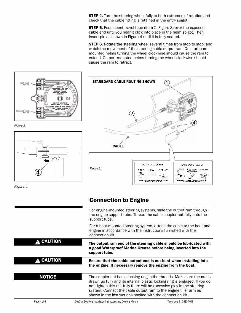
Figure 3.
Figure 4.
➀
➁
➃
CABLE
➃
Forengine-mountedsteeringsystems,slidetheoutputramthroughthe engine support tube. Thread the cable coupler nut fully onto the support tube.
Foraboat-mountedsteeringsystem,attachthecabletotheboatandengine in accordance with the instructions furnished with the connection kit.
NOTICE
Ensure that the cable output end is not bent when installing into the engine. If necessary remove the engine from the boat.
CAUTION
Connection to Engine
STEP 4.Turnthesteeringwheelfullytobothextremesofrotationandcheck that the cable fitting is retained in the entry spigot.
STEP 5.Feedspenttraveltube(item2,Figure3)overtheexposedcable end until you hear it click into place in the helm spigot. Then insertpinasshowninFigure4untilitisfullyseated.
STEP 6. Rotate the steering wheel several times from stop to stop, and watch the movement of the steering cable output ram. On starboard mounted helms turning the wheel clockwise should cause the ram to extend.Onportmountedhelmsturningthewheelclockwiseshouldcause the ram to retract.
CAUTION The output ram end of the steering cable should be lubricated with a good Waterproof Marine Grease before being inserted into the support tube.
Thecouplernuthasalockingringinthethreads.Makesurethenutisdrawn up fully and its internal plastic locking ring is engaged. If you do nottightenthisnutfullytherewillbeexcessiveplayinthesteeringsystem. Connect the cable output ram to the engine tiller arm as shown in the instructions packed with the connection kit.
Figure 2.
STARBOARD CABLE ROUTING SHOWN
Page 4 of 6 SeaStar Solutions Installation Instructions and Owner’s Manual Telephone: 610-495-7011

ITEM QTY DESCRIPTION
1 1 Helm 2 1 Spent Travel Tube *3 3 1/4 x 3/4” Long Hex Bolt 4 2 Pin (1 with white tag, 1 without tag)
Helm Parts List
* Pictured in bezel kit instructions.
It is possible to over trim the engine and increase the steering torque to the point that the steering wheel cannot be turned. This may give the impression that the steering is “locked”. This condition can occur more when jack plates are used to raise the engine on the transom, and can only be overcome by reducing the boat speed or engine trim out position. Until you are completely familiar with the boat and the effects of power trim, make all adjustments of trim with extreme caution.
Loosening or loss of one or more fasteners may cause failure of the steering system, resulting in loss of steering control and could cause property damage, injury, or death.
DO NOT cover cracks with tape or other sealants, this will create a hazard in which the cable can fail suddenly without warning, resulting in property damage, injury, or death.
DANGER
DANGER
1. After a few hours of operation and at frequent intervals thereafter, check all fasteners and the complete steering system for security and integrity.
2.Keepallmovingpartsfreefrombuild-upofsaltandotherforeignmaterial. This will affect their operation and create steering problems. Periodically remove the cable, clean support tube and telescopic end of cable thoroughly and lubricate with a waterproof marine grease.
3. Periodically inspect for corrosion. Any parts affected by corrosion mustbereplaced.Whenreplacinghardware,self-lockinghardwareasoriginally supplied must be used.
4. Periodically inspect steering cable for cracks or other damage. If any is found the cable must be replaced.
Boat builder and boat dealer, please supply these Installation Instructions and Owner’s Manual with the delivery of boat. Boat owner keep these instructions with your boat for future reference. Boat owner consult with your boat builder, boat dealer, or SeaStar Solutions if you have any questions regarding these instructions.
NOTICE
Operation & Maintenance Notes CAUTION
DANGER If steering cable is stiff in operation, it is unsafe to use and must be replaced immediately.
web: www.seastarsolutions.com SeaStar Solutions 640 North Lewis Road, Limerick, PA 19468 USA Page 5 of 6

© 2014 MaRInEaCquISITIOn(uS)InC.
PART # IS-SH5094-1 08-2014 Rev. 0
ISO 8848