installation instructions and technical guide - · pdf fileinstallation instructions and...
TRANSCRIPT
Installation instructions and technical guideGas condensing boilerCGB-75 Wall mounted gas boilerCGB-100 Wall mounted gas boiler
Document no. 30 62 555 Subject to modifications 07/09 GB
Wolf GmbH · Postfach 1380 · D-84048 Mainburg · Tel. +49-8751/74-0 · Fax +49-8751/741600 · Internet: www.wolf-heiztechnik.de
2 30 62 555_0709
IndexIndex ....................................................................................................... PageSafety instructions ........................................................................................................3
Standards and regulations........................................................................................ 4-5
Control / Function / Operation ................................................................................. 6-7
Delivered condition / standard delivery.........................................................................8
Layout CGB-75 / CGB-100 ...........................................................................................9
Installation instructions ...............................................................................................10
Installation ..................................................................................................................11
Dimensions / installation dimensions..........................................................................12
Installation ............................................................................................................ 13-16
Installation of the balanced flue system....................................17
Power connection ............................................................... 18-21
Filling the system ......................................................................22
Conversion to other gas types ............................................ 23-24
checking the gas supply pressure ...........................................25
Commissioning / setting the BUS address ...............................26
Displaying / modifying control parameters................................27
Adjusting the modulating pump ................................................28
Limiting the maximum output....................................................29
Testing the combustion parameters..........................................30
CO2 adjustments ................................................................ 31-32
Commissioning report...............................................................33
Maintenance (see maintenance instructions provided)
Maintenance and design data .............................................................................. 34-35
Design information................................................................................................ 36-59
Water treatment ........................................................................36
System log ................................................................................37
Function description/system design ................................... 38-39
System examples 1-6 ......................................................... 40-45
Key to system examples...........................................................46
Parts list for the system examples ............................................47
Balanced flue routing .......................................................... 48-57
Wiring diagram ...........................................................................................................58
Specification ...............................................................................................................59
Troubleshooting .................................................................................................... 60-61
Notes .................................................................................................................... 62-63
EC declaration of conformity ......................................................................................64

330 62 555_0709
Safety instructionsThe following symbols are used in conjunction with these important instructions concerning personal safety, as well as operational reliability.
"Safety instructions" are instructions with which you must comply exactly, to prevent risks and injuries to individuals and material losses.
Danger through 'live' electrical components! NB: Switch OFF the ON/OFF switch before
removing the casing. Never touch electrical components or contacts
when the ON/OFF switch is in the ON position! This results in a risk of electrocution that may lead to injury or death.
The main supply terminals are 'live' even when the ON/OFF switch is in the OFF position.
"Note" indicates technical instructions that you must observe to prevent material losses and boiler malfunctions.
General notes
Maintenance work must only be carried out by a qualified heating contractor. Regular maintenance and the exclusive use of original Wolf spare parts are necessary preconditions for trouble-free operation and a long service life. We therefore recommend you arrange a maintenance contract with a local heating contractor.
Figure: Terminal box - danger from electrical voltage
Figure: Ignition transformer, high voltage ignition electrode, heat exchangerDanger from electrical voltage Risk of burning from hot components
Figure: Gas combination valveDanger from electrical voltageEscaping gas may cause poisoning or an explosion
Figure: Gas connectionEscaping gas may cause poisoning or an explosion
Seal the front casing tightly with screws after completing the service. There is a risk of carbon monoxide poisoning if the flue system is faulty.
NB

4 30 62 555_0709
Standards and regulations
Note: Please read these instructions carefully before the installation and keep them in a safe place. Please also note the technical information in the appendix.
Any damage or loss resulting from technical modifications to the control unit or to the control components are excluded from our liability.Incorrect use can lead to a risk to life and limb or to a risk of material losses.
Only use propane compliant with local regulations, otherwise faults may arise through the starting characteristics and operation of the gas condensing boiler; this in turn may lead to boiler damage and risk of injury. Poorly vented LPG tanks can lead to ignition problems. In such cases, contact your local LPG supplier.
Note: Please read these instructions carefully before the installation and keep them in a safe place. Please also note the technical information in the appendix.
Requirements
The installation of the boiler must be in accordance with the relevant requirements of Gas Safety (Installation and Use) Regulations 1998, Health and Safety Document No. 635 (The Electricity at Work Regulations 1989), BS 7671 (IEE Wiring Regulations) and the Water Supply (Water Fitting) Regulations 1999, or The Water Bylaws 2000 (Scotland). It should also be in accordance with the relevant requirements of the Local Authority, Building Regulations, including amendments to the Approved Documents Part L and J 2002, The Building Regulations (Scotland), The Building Regulations (Northern Ireland) and the relevant recommendations of the following British Standards:
BS 5440: Flues and ventilation of gas fired boilers not exceeding 70 kW net:
- Part 1: Flues - Part 2: VentilationBS 5449: Specification for forced circulation hot water for
domestic premises. BS 5546: Specification for forced circulation hot water for
domestic premises.BS 6700: Services supplying water for domestic use within
buildings and their curtilages. BS 6798: Specification for installation of gas fired boilers
not exceeding 60 kW input.BS 6891: Specification for installation of low pressure gas
pipework up to 28 mm (R1") in domestic premises (2nd family gas).
BS 7593: Treatment of water in domestic hot water central heating systems.
Institute of Gas Engineers Publication IGE/UP/7/1998:"Guide for gas installations in timber framed housing"
Important: The appliance must be installed and serviced by a competent person as stated in the Gas Safety (Installation and Use) Regulations 1998. In IE, the installation must be in accordance with the current edition of I.S,813 "Domestic Gas Installations", the current Building Regulations and reference should be made to the current ECI rules for electrical installation.
When tightening or loosening threaded connections always use suitable open-ended spanners (not pipe wrench, or extensions, etc.). Incorrect use and/or unsuitable tools can lead to damage (e.g. gas or water leaks)!
Any damage or loss resulting from technical modifications to the control unit or to the control components are excluded from our liability.Incorrect use can lead to a risk to life and limb or to a risk of material losses.
Obtain the permission of your mains gas supplier and flue gas inspector prior to the installation of Wolf gas fired boilers [where appropriate].
Wolf gas fired boilers must only be installed by a recognised heating contractor. This heating contractor will also be responsible for the correct installation and commissioning of the heating system.
The following regulations, rules and guidelines must be observed during installation:- VDE 0722 / EN50165 Electr ical equipment of heat
generators with non-electrical heating systems
- DIN EN 12828 Heating systems in buildings, des ign ing hot water heat ing systems
- EN 60335-1 Safety of electrical equipment for domestic use and similar purposes
- VDE 0470 / EN 60529 Protection through housings

530 62 555_0709
Gas condensing boiler CGB-...
Gas condensing boiler in accordance with EN 297 / EN 437 / EN 483 / EN 677 / EN 625/pr EN 13203 and EU Directive 90/396/EEC (Gas Consumer Equipment), 92/42/EEC (Efficiency guideline), 2006/95/EU (Low Voltage Directive) and 2004/108/EU (EMC Directive), with electronic ignition and electronic flue gas temperature monitoring, for low temperature heating and DHW production in heating systems with flow temperatures up to 95 °C and 6 bar permissible operating pressure in accordance with EN 12 828. The Wolf gas condensing boiler is also approved for installation in garages.
Standards and regulations
Figure: Wolf gas condensing boiler
Open flue gas condensing boilers must only be installed in a room which complies with the appropriate ventilation requirements. Otherwise there is a risk of asphyxiation or poisoning. Read these installation and maintenance instructions before installing the boiler. Also take the technical engineering information into consideration.
Note: The DHW temperature should be limited to a maximum of 55 °C if the hardness of the hot water is more than 2.86 mmol/l. A reduced DHW temperature prevents excessive scaling. This cuts the level of maintenance and energy input.

6 30 62 555_0709
Control / Function / Operation
DHW temperature selection. When gas condensing boilers are combined with a DHW cylinder, setting 1-9 corresponds to a cylinder temperature of 15-65 °C. The DHW temperature selector setting becomes ineffective when the system is combined with a digital room thermostat or a weather-compensated controller. The temperature will then be selected at the controller (accessory).
Heating water temperature selection. Settings 2-8 correspond, when factory-set, to a heating water temperature of 20-80 °C. The heating water thermostat setting becomes ineffective when the system is combined with a digital room thermostat or a weather-compensated controller.
ON/OFF switchThe condensing boiler is OFF in position 0.
Reset A fault is reset by pressing the reset button which will also restart the system. Pressing the reset button reactivates the system, if there was no fault.
ON/OFF switch DHW temperature
selector
Reset button
Heating water temperature
selector
Illuminated signal ring
Thermometer
Illuminated signal ring as status indicatorDisplay ExplanationFlashing green Standby (power supply ON; no heat demand)Constant green light Heat demand: Pump running; burner OFFFlashing yellow Emissions test modeConstant yellow light Burner ON; flame steadyFlashing red Fault

730 62 555_0709
Control / Function / Operation
Note: The number of times the condensing boiler can be started in heating mode is limited electronically. This limit can be bypassed by pressing the reset button. Then, the boiler starts immediately, as soon as there is a heating demand.
In summer mode, the circulation pump operates for approx. 30 seconds after a maximum idle period of 24 hours.
Anti-seizing pump protection
Setting Winter mode (settings 2 to 8)In winter mode, the boiler heats to the temperature selected at the heating water temperature controller. According to the pump operating mode, the circulation pump operates constantly (factory setting) or only in parallel with the burner activation / run-on period.
Summer modeWinter mode is disabled by rotating the heating water temperature selector into position
. The boiler then operates in summer mode. Summer mode (heating OFF) means only DHW heating. Frost protection for the heating system and pump anti-seizing protection, however, remain enabled.
Emissions test modeEmissions test mode is activated by rotating the heating water temperature selector into position . The illuminated signal ring flashes yellow. After the emissions test mode has been activated, the boiler will heat with the selected maximum heating output. Any previous cycle block will be cancelled. The emissions test mode terminates after 15 minutes or when the maximum flow temperature has been exceeded. To reactivate, turn the heating water temperature selector anti-clockwise and then back to .
8 30 62 555_0709
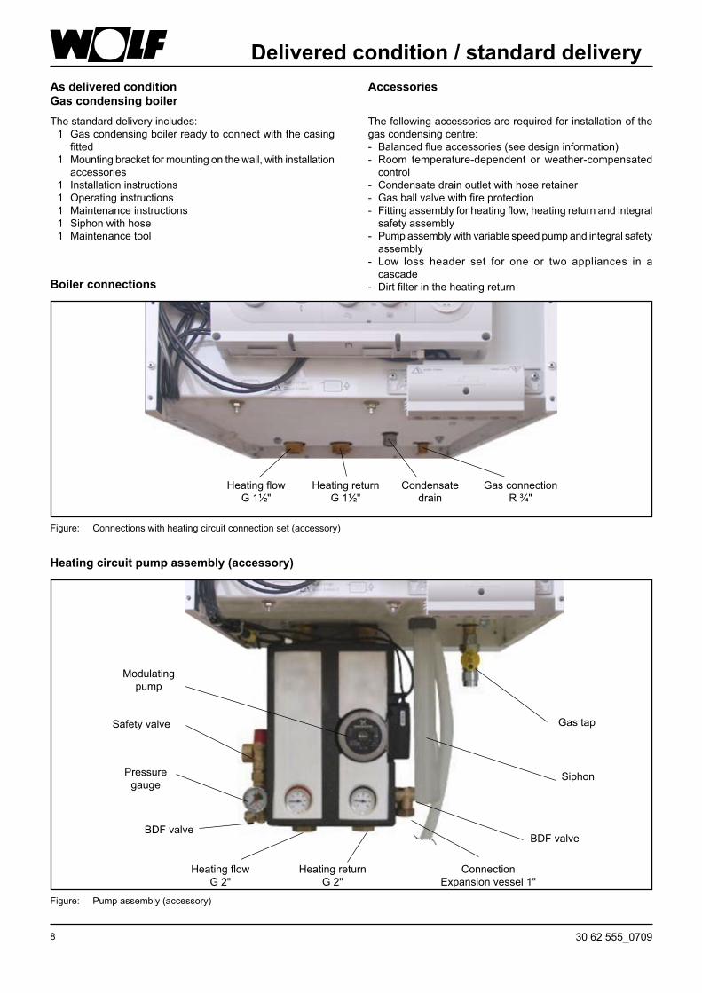
Delivered condition / standard deliveryAs delivered conditionGas condensing boilerThe standard delivery includes: 1 Gas condensing boiler ready to connect with the casing fitted 1 Mounting bracket for mounting on the wall, with installation accessories 1 Installation instructions 1 Operating instructions 1 Maintenance instructions 1 Siphon with hose 1 Maintenance tool
Accessories
The following accessories are required for installation of the gas condensing centre:- Balanced flue accessories (see design information)- Room temperature-dependent or weather-compensated
control- Condensate drain outlet with hose retainer- Gas ball valve with fire protection- Fitting assembly for heating flow, heating return and integral
safety assembly- Pump assembly with variable speed pump and integral safety
assembly- Low loss header set for one or two appliances in a
cascade- Dirt filter in the heating returnBoiler connections
Figure: Connections with heating circuit connection set (accessory)
Heating flowG 1½"
Gas connectionR ¾"
Heating returnG 1½"
Condensate drain
Heating circuit pump assembly (accessory)
Figure: Pump assembly (accessory)
Heating flowG 2"
Heating returnG 2"
Siphon
Gas tap
connectionExpansion vessel 1"
BDF valveBDF valve
Pressure gauge
Safety valve
Modulating pump

930 62 555_0709
CGB-75 / CGB-100
Layout
Quick-acting air vent valve
Gas fan
Heating water heat exchanger
Condensate siphon
Gas combination valve
Heating return Gas supply pipe
Flue gas sensor
Combustion chamber casing
Return sensor
Combustion chamber temperature limiter
Flue
Heating flow
Burner
Flow sensor
Temperature limiterflow
Inlet pipe
Flue gas test point
Ventilation air test point
Gas:air mixing chamber
Flash trap
Displacement device
Flow switch
Gas restrictor
Monitoring electrode
Ignition electrode
Non-return valve

10 30 62 555_0709
First determine where the appliance is to be installed.In your deliberations, consider the flue gas outlet, the lateral clearances towards walls and ceilings and any existing connections for gas, central heating, DHW and electrics.
Installation instructions
Sound insulation: Under certain critical installation conditions (e.g. installation on a drywall), additional measures may be necessary to soundproof the boiler. In this case use soundproof plugs and, if necessary, rubber mounts or insulation strips.
When using alow loss header set min. 830 mm
min.350 mm
min.350 mm
Electrical connection must be made on site.
Please maintain the 350 mm clearance to the ceiling to enable inspection and maintenance work on the boiler to be carried out, otherwise the necessary inspection and function tests on components cannot be ensured during maintenance. The drain hoses must be secured with the retainer above the drain outlet (siphon). The drain must be able to be inspected.
The appliance may only be installed in rooms that are safe from the risk of frost.
General notes
Clearance between the boiler and combustible materials or components is not required, as temperatures are limited to 85 °C at the rated boiler output. However, explosive and easily combustible materials must not be used in the boiler room; these would create a risk of fire or explosion.
During boiler installation, ensure that no contaminants (e.g. drilling swarf) enter the gas boiler, otherwise faults may develop. The installation room and the combustion air
supplied to the appliance must be free from chemicals, e.g. fluoride and chlorine or sulphur. Such materials are contained in sprays, paints, adhesives, solvents and cleaning agents. Under the most unfavourable conditions, these may lead to corrosion, even in the flue gas system.
NB

1130 62 555_0709
Installation
Initially, determine the location for the installation of the gas condensing boiler.In your deliberations, consider the flue gas outlet, the lateral clearances towards walls and ceilings and any existing connections for gas, central heating, DHW and electrics.
Opening the casing coverWe recommend you remove the casing cover during the installation.Release the casing cover with the l.h. and r.h. screw. Release the bottom of the casing cover and unhook at the top.
Mounting the boiler with a mounting bracket During installation of the gas condensing boiler, ensure that all fixings are strong enough to carry its weight. Also consider the wall consistency, otherwise gas or water may escape which could lead to explosions and flooding.
ScrewsFigure: Undoing screws
Figure: Fixing holes for mounting bracket
min
. 446
mm
Ceiling
- Mark the holes to be drilled for the mounting bracket, taking into consideration the minimum clearances.
- Insert the rawl plugs and fit the mounting bracket with the coach bolts and washers supplied.
- Hang the gas condensing boiler with the mounting stays into the mounting bracket.
Mounting stays
Figure: Mounting brace on the condensing boiler
Seal the front casing tightly with screws after completing the service. There is a risk of carbon monoxide poisoning if the flue system is faulty.
12 30 62 555_0709
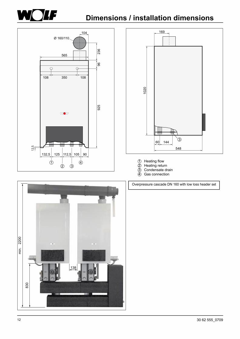
Dimensions / installation dimensions
1 Heating flow2 Heating return3 Condensate drain4 Gas connection
min
.22
00
830
138
Overpressure cascade DN 160 with low loss header set
Ø 160/110
132,5
2 3
125 112,5 105 90
565
12,5
108 108350
104
236
925
96
1 4

1330 62 555_0709
InstallationHeating circuit connection setWe recommend you connect the heating system with the aid of a heating circuit connection set. Connection set comprising: Connection to the appliance with flat gasket, connection to heating flow/return with ball valves 1" female thread.
Note:Provide a BDF valve at the lowest system point. Figure: Heating circuit connection set (accessory)
Figure: Pump assembly (accessory)
The CGB-75 and CGB-100 have not been fitted with an expansion vessel at the factory. This must be fitted externally (available from the Wolf accessories range). Ensure the expansion vessel is correctly sized.
There must be no shut-off valve between the expansion vessel and the condensing boiler, otherwise the pressure build-up would permanently damage the boiler during heating. There is a risk of system components rupturing, giving rise to a risk of scalding.
Exceptions are cap valves upstream of the expansion vessel. The pump or fitting assembly includes a 3 bar safety valve (6 bar safety valve is available as an accessory). Route the blow-off line into a drain funnel. The minimum system pressure is 1.0 bar. The boilers are approved exclusively for sealed systems of up to 6 bar. The maximum flow temperature is factory-set to 80 °C and may be adjusted to 90 °C if required.
Safety equipment
14 30 62 555_0709
InstallationNote:Provide a BDF valve at the lowest system point.
Information on scaling Scaling can be strongly influenced particularly through the method of commissioning. Heat the system at the lowest output with an even and adequate throughput. For multi-boiler systems it is recommended to commission all boilers simultaneously to prevent the overall amount of lime concentrating on the heat exchanger surface of an individual boiler.
The minimum system pressure is 1.0 bar.The gas condensing boiler is approved exclusively for sealed systems of up to 6 bar. The maximum flow temperature is factory-set to 80 °C and may be adjusted to 90 °C if required. Generally, the flow temperature is 80 °C for DHW operation.
Safety equipment
General requirements
There is a risk of damage to the boiler resulting from water leaks, poor heat transfer or corrosion.
- Before connecting the gas condensing boiler, flush the heating system to remove residues such as welding pearls, hemp, putty, sludge sediments, etc. from the pipework
- Clean the dirt trap- The automatic air vent valve for the appliance must be
opened during operation- The max. flow rate of 100 l/min (6000 l/m³) must not be
exceeded- Domestic hot water or partially desalinated domestic hot
water should be used as fill water and top-up water- If an ingress of oxygen cannot be ruled out, a system
separation is advisable- Heating water pH value must be between 6.5 and 8.5- Limitation of the fill water hardness: Min. 2 °dH, max. 11 °dH, at > 10 l/kW see Design information,
water treatment- De-scaling using single-stage ion exchangers is not
permissible. For permissible methods, see Design information, water treatment
- Inhibitors and antifreeze are not permissible- A system log must be kept (see Design information, water
treatment)Additional requirements for operation without a low loss header
- Systems with only one CGB-75/100
Heating water
The maximum flow rate must not exceed 6000 l/h (100l/min).
Before commissioning, all hydraulic pipes must undergo a tightness test:Test pressure on heating water side max. 8 bar.Prior to testing, close the shut-off valves in the heating circuit for the appliance, because otherwise, the safety valve (accessory) opens at 3 bar. The appliance has already been tested at the factory for tightness at 6 bar.If the appliance is not watertight, there is a risk of leaks and resulting material losses.
- Sludge separator in the boiler return of the CGB-75/100- Desalination of the heating water to < 3 °dH- Control of the cylinder heating only via the MM module
(configurations 1 and 10)- Cylinder primary pump at least DN 25 with at least 6 m
head- The max. flow temperature must be adjusted with parameter
HG08 to 75 °C
The design information for water treatment must be observed, otherwise system damage due to water leaks may occur.
The manufacturer does not assume liability for any damage to the heat exchanger caused by oxygen diffusion in the heating water. In the event of oxygen penetrating the system, we recommend a system separation through the interconnection of a heat exchanger.

1530 62 555_0709
InstallationCondensate drain connectionConnect the siphon supplied to the connector on the combustion chamber pan.
Please note: The siphon must be filled with water prior to commissioning.
If condensate is directly routed to the public sewer, ensure ventilation, so that the public sewer cannot affect the condensing boiler.
Figure: Siphon
Siphon
There is a risk of poisoning through flue gases being expelled if the appliance is operated with an empty siphon. Therefore, fill the siphon with water prior to commissioning. Undo the siphon, remove and fill until water runs out of the drain hole on the side. Refit the siphon and ensure the gasket seals tightly.
The condensate must only be routed through pipes that are resistant.Observe the relevant instructions if you install a neutralising system (accessory).
Figure: Neutralising system (accessory)
Condensate pumpWhen using a condensate pump, the alarm output can be connected at connection E1. Set the boiler parameter HG13 to "2".The alarm output switches the appliance OFF if condensate cannot be pumped out correctly.
16 30 62 555_0709
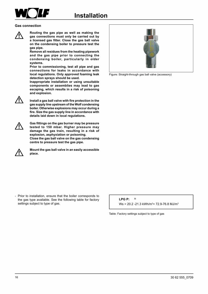
InstallationGas connection
Figure: Straight-through gas ball valve (accessory)
Routing the gas pipe as well as making the gas connections must only be carried out by a licensed gas fitter. Close the gas ball valve on the condensing boiler to pressure test the gas pipe.Remove all residues from the heating pipework and the gas pipe prior to connecting the condensing boiler, particularly in older systems.Prior to commissioning, test all pipe and gas connections for leaks in accordance with local regulations. Only approved foaming leak detection sprays should be used.Inappropriate installation or using unsuitable components or assemblies may lead to gas escaping, which results in a risk of poisoning and explosion.
Install a gas ball valve with fire protection in the gas supply line upstream of the Wolf condensing boiler. Otherwise explosions may occur during a fire. Size the gas supply line in accordance with details laid down in local regulations.
Gas fittings on the gas burner may be pressure tested to 150 mbar. Higher pressure may damage the gas train, resulting in a risk of explosion, asphyxiation or poisoning.Close the gas ball valve on the gas condensing centre to pressure test the gas pipe.
Mount the gas ball valve in an easily accessible place.
- Prior to installation, ensure that the boiler corresponds to the gas type available. See the following table for factory settings subject to type of gas.
Table: Factory settings subject to type of gas
LPG P: 2)
Ws = 20.2 -21.3 kWh/m3= 72.9-76.8 MJ/m3

1730 62 555_0709
Installation of the balanced flue systemFor flues and concentric balanced flue systems, use only original Wolf components. Please observe the technical information regarding balanced flue systems prior to installing the flue or the balanced flue connection.
NB
With low outside temperatures, the water vapour contained in the flue gas may condense and freeze on the balanced flue. Prevent ice from falling through on-site measures, e.g. the installation of a snow catcher grille.
The flue gas test ports must remain accessible for your local flue gas inspector, even after fitting the ceiling bezels.
Figure: Example: Balanced flue system
NB
18 30 62 555_0709
Electrical connectionGeneral notes
The installation must be carried out by a licensed electrical contractor. Observe electrical regulations and those of the local power supply utility.
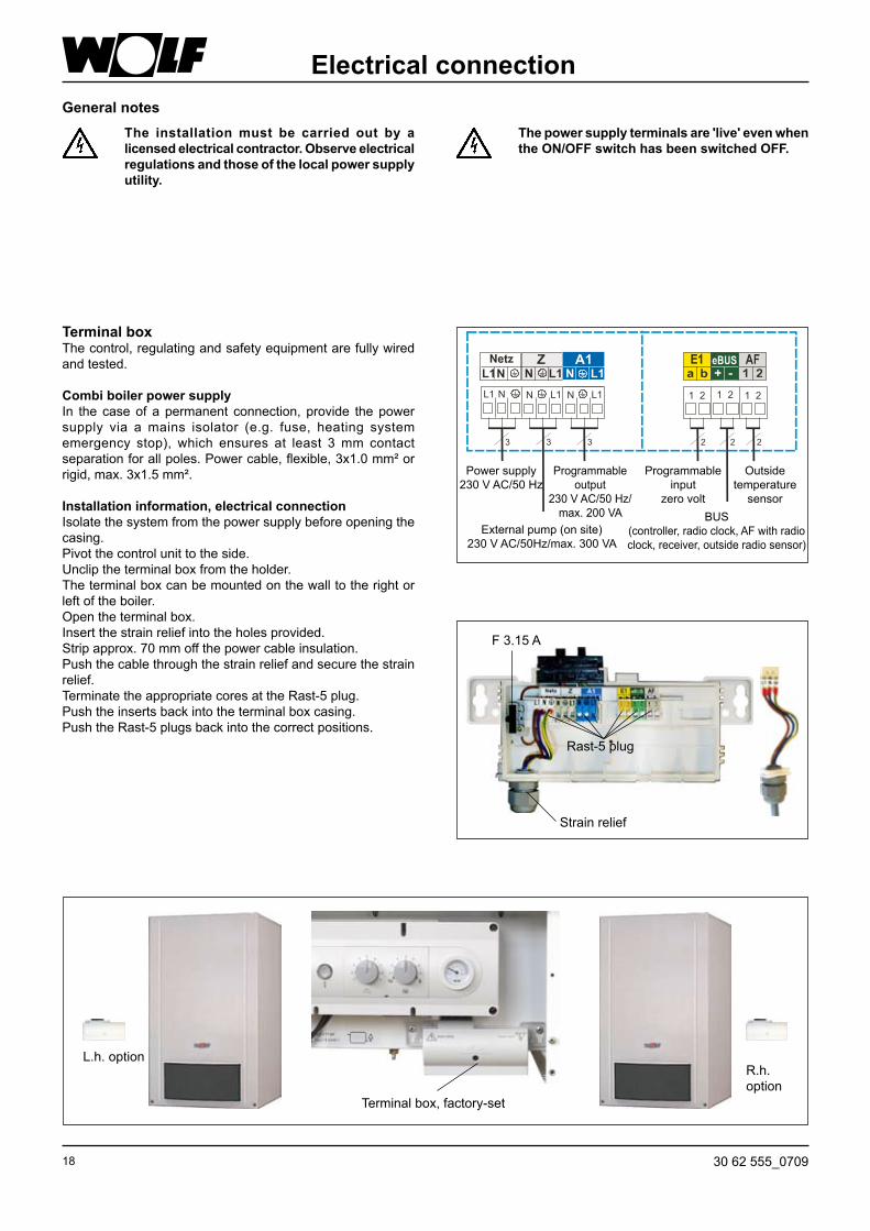
Terminal boxThe control, regulating and safety equipment are fully wired and tested.
Combi boiler power supplyIn the case of a permanent connection, provide the power supply via a mains isolator (e.g. fuse, heating system emergency stop), which ensures at least 3 mm contact separation for all poles. Power cable, flexible, 3x1.0 mm² or rigid, max. 3x1.5 mm².
Installation information, electrical connectionIsolate the system from the power supply before opening the casing.Pivot the control unit to the side.Unclip the terminal box from the holder.The terminal box can be mounted on the wall to the right or left of the boiler.Open the terminal box.Insert the strain relief into the holes provided.Strip approx. 70 mm off the power cable insulation.Push the cable through the strain relief and secure the strain relief.Terminate the appropriate cores at the Rast-5 plug.Push the inserts back into the terminal box casing.Push the Rast-5 plugs back into the correct positions.
The power supply terminals are 'live' even when the ON/OFF switch has been switched OFF.
Z A1N
N
NL1L1 L1
1 2 1 21 2L1 L1L1 N NN
3 3 3 2 2 2
Power supply230 V AC/50 Hz
External pump (on site)230 V AC/50Hz/max. 300 VA
Programmableoutput
230 V AC/50 Hz/max. 200 VA
Programmableinput
zero volt
Outside temperature
sensorBUS
(controller, radio clock, AF with radio clock, receiver, outside radio sensor)
Strain relief
F 3.15 A
Rast-5 plug
Terminal box, factory-set
L.h. optionR.h. option

1930 62 555_0709
Electrical connection
DHW cylinder sensor connection - When a cylinder is to be connected, the blue socket of the
cylinder sensor must be connected to the blue plug of the control unit.
- Observe the cylinder installation instructions.
Figure: Blue plug, cylinder sensor connection
Blue plug
Isolate the condensing boiler from the power supply prior to changing a fuse. The ON/OFF switch on the boiler does not provide separation from the power supply.Danger through 'live' electrical components. Never touch electrical components or contacts as long as the condensing boiler has not been isolated from the power supply. Danger of death.
Changing a fuse
Figure: Terminal box cover open
Fuse
Figure: Connection output A1
Connection output A1 (230 V AC; 200 VA)Insert the cable glands into the terminal box. Insert and secure the connecting cable through the cable gland. Connect the connecting cable to terminals L1, N and .The parameters for output A1 are described in the table on the following page.
Connection, external heating circuit pump (on site) (230 V AC max. 300 VA)Insert the cable glands into the terminal box. Insert and secure the connecting cable through the cable gland.Connect the pump 230 V AC to terminals L1 and N and .The pump is activated when there is demand in heating, DHW or frost protection mode.
Figure: Connection, heating circuit pump

20 30 62 555_0709
Electrical connectionThe functions of output A1 can be scanned and adjusted with Wolf control accessories with eBUS capability.The following functions can be allocated to output A1:
Code Explanation
0 No function Output A1 is not activated
1 DHW circulation pump 100% Output A1 is activated by control accessories (timed) if DHW has been enabled. Output A1 is constantly activated when no accessory controller is installed.
2 DHW circulation pump 50% Output A1 is activated in cycles by control accessories (timed) if DHW has been enabled. 5 minutes ON and 5 minutes OFF. Output A1 is constantly cycled in 5 minute intervals when no accessory controller is installed.
3 DHW circulation pump 20% Output A1 is activated in cycles by control accessories (timed) if DHW has been enabled. 2 minutes ON and 8 minutes OFF. Output A1 cycles constantly when no accessory controller is installed.
4 Alarm output Output A1 is activated 4 minutes after a fault.
5 Flame detector Output A1 is activated after a flame has been recognised.
6 Cylinder primary pump (factory setting for A1) Output A1 is activated during cylinder heating.
7 Ventilation air damper Output A1 is activated before each burner start. The burner will, however, only be enabled after input E1 has been closed. Important: In any case, input E1 must also be programmed as "Ventilation air damper"! For the feedback to input E1 use a zero volt contact (24 V). Otherwise, use an on-site relay for potential separation.
8 External ventilation Output A1 is activated inverted to the gas combination valve. Switching off external ventilation equipment (e.g. extractor fan) during burner operation is only required if the boiler is operated as an open flue system.
9 External LPG valve Output A1 is activated in parallel to the gas combination valve.
10 External pump Output A1 switches synchronously with the heating circuit pump (HKP); used for example with system separation.
2130 62 555_0709
Electrical connection
The functions of input E1 can be scanned and adjusted with Wolf control accessories with eBUS capability. The following functions can be allocated to input E1:
Code Explanation
0 No function Input E1 is not taken into consideration by the control unit
1 Room thermostat (factory setting) With open input E1, heating operation will be blocked (summer mode), independent of any digital Wolf control accessories.
2 Maximum thermostat, system pressure switch or condensate lifting system Connection option for a maximum thermostat, system pressure switch or condensate lifting system. To enable the burner, input E1 must be closed. As long as the contact is open, the burner will remain blocked for DHW and central heating, incl. emissions test mode and frost protection.
3 N / A
4 Flow limiter Connection option for an additional water flow limiter. After pump activation, input E1 must be closed within 12 seconds. Where this is not the case, the burner will be switched OFF, and fault 41 will be displayed.
5 Monitoring the ventilation air damper See parameters of output A1, no. 7. Ventilation air damper
8 Burner block (BOB) Operation without burner Closed contact, burner blocked Heating circuit pump and cylinder primary pump run in standard mode In emissions test mode and frost protection the burner is enabled Open contact enables the burner again
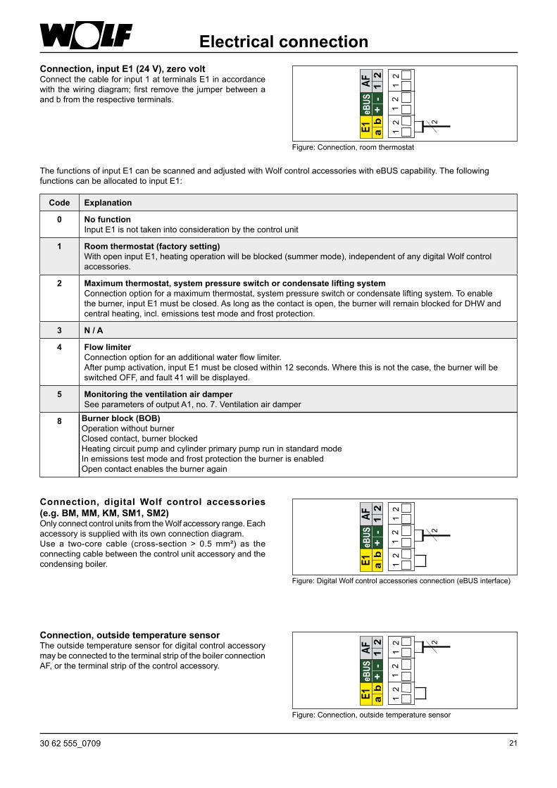
Connection, input E1 (24 V), zero voltConnect the cable for input 1 at terminals E1 in accordance with the wiring diagram; first remove the jumper between a and b from the respective terminals.
Figure: Connection, room thermostat
Connection, digital Wolf control accessories (e.g. BM, MM, KM, SM1, SM2)Only connect control units from the Wolf accessory range. Each accessory is supplied with its own connection diagram.Use a two-core cable (cross-section > 0.5 mm²) as the connecting cable between the control unit accessory and the condensing boiler.
Figure: Digital Wolf control accessories connection (eBUS interface)
Connection, outside temperature sensorThe outside temperature sensor for digital control accessory may be connected to the terminal strip of the boiler connection AF, or the terminal strip of the control accessory.
Figure: Connection, outside temperature sensor

22 30 62 555_0709
Filling the systemFill the system and vent it properly to safeguard the perfect functioning of the condensing boiler.
Before connecting the gas condensing boiler, flush the heating system to remove residues such as welding pearls, hemp, putty, etc. from the pipework. Check the dirt filter.
- The gas tap must be closed
- The locking cap on the quick-acting air vent valve should not be undone
- Open all radiator valves
- Open the return valves, and the heat exchanger will then be filled steadily with water from below
- With the entire heating system and boiler in a cold condition, slowly fill the system via the inspection/BDF valve at the return until 2 bar pressure is indicated
- Open the flow valves on the condensing boiler
- Fill the heating system to 2 bar pressure. In operation, the pressure gauge (on site) must indicate between 1.5 and 2.5 bar
- Check the entire system for water leaks
- Open the air vent valve
- Start the condensing boiler, set the heating water temperature selector to position "2" (pump running, illuminated signal ring (status display) constantly green)
- Vent the pump; for this, briefly open and then retighten the air vent screw
- Vent the heating circuit completely, switching the condensing boiler ON for 5 seconds and OFF for 5 seconds at the ON/OFF switch, five times in succession
- When the system pressure drops below 1.5 bar, top up the water
- Open the gas ball valve
- Press the reset button
Note: - In constant mode, the heating circuit is automatically vented via the air vent valve.
- At a system pressure below 1.0 bar, the boiler will enter a fault state
BDF valve
ON/OFF switch ThermometerReset button
Automatic air vent valve
Air vent valve, heating circuit pump
- Fill siphon with water and fit it to the boiler
Siphon
NB

2330 62 555_0709
Conversion to other gas types (if required)
The gas condensing boilers CGB-75/CGB-100 are equipped as part of the standard delivery for operation with natural gas H (G20).For operation with LPG (G31), the gas restrictor must be replaced.
Re-assemble in reverse order.Note: During conversion from LPG to natural gas, the flue gas orifice plate (see Conversion to LPG, point 9, page 24) must
be removed prior to assembly.
5)
Remove the fitted gas restrictor and replace it with the gas restrictor designated for LPG (G31).
Gas restrictor
4)
Undo the gas combination valve from the mixing chamber for gas/air (four SW8 screws).
4 x screws SW8
Unplug the connector (first undo Phillips head screws)
1)
Undo gas connection at the gas combination valve
2)
3)
Undo the mixing chamber from the ventilator (three Allen screws 5 mm), and remove air inlet pipe where necessary
6)
After assembly of the gas restrictor, gas combination valve and air inlet pipe, push the O-ring lubricated with silicone grease into the packing groove of the fan and refit the mixing chamber.
O-ring
1
2
24 30 62 555_0709
Conversion to other gas types (if required)
Note: During conversion to LPG, a flue gas orifice plate must also be installed in the condensate pan as follows. This installation step is carried out prior to the installation of the mixing chamber and full assembly.
Slide the balanced flue locking mechanism in the direction of the arrow. Pull the flue pipe up out of the condensate pan.
8)
10) Updating the type plate
Cut out the relevant lines from the type plate supplied and affix them over the relevant lines on the appliance type plate.
Conversion type plate Figure: Updating the type plate
After removing the upper casing cover, undo the self-tapping screw at the balanced flue locking mechanism.
7)
Conversion sets for CGB-75/100 for conversion to other gas types: (Please state the corresponding part number when ordering)
Conversion to LPG P (G31) Part no. 86 12 714 ID 740** ID imprinted on gas restrictor
Place the flue gas orifice plate Ø 53 mm into the condensate pan and insert the flue pipe again.Note: During conversion from LPG to natural gas, the
flue gas orifice plate must be removed. Fit the mixing chamber as described under point 6).
Re-assemble in reverse order.
9)
Flue gas orifice plate

2530 62 555_0709
Figure: Shut-off valves
Checking the gas supply pressure
- The condensing boiler must be switched OFF; open the gas shut-off valve
Release the casing cover with the l.h. and r.h. screw. Release the bottom of the casing cover and unhook at the top
- Release the plug at test nipple and vent the gas supply pipe
- Connect the differential pressure meter or U-tube manometer to the test nipple at "+", with "-" against atmosphere
- Switch ON the ON/OFF switch- After starting the boiler, check the supply pressure at the
differential pressure meter.
Figure: Checking the gas supply pressure
- Switch OFF ON/OFF switch; close the gas shut-off valve- Remove the differential pressure meter and re-seal the test nipple with plug - Open the gas shut-off valve- Check the test nipple for gas-tightness- Complete the enclosed notice and affix to the inside of the
casing- Close the boiler again
If any screws are not tightened, there is a danger of gas escaping, leading to a risk of explosion, asphyxiation or poisoning.
LPG:If the supply pressure (flow pressure) is outside the 25 to 45 mbar range (supply pressure 37 mbar) or 43 to 57 mbar range (supply pressure 50 mbar), adjustments must not be carried out and the boiler must not be started. There is a risk of faulty boiler functions.
Natural gas:If the supply pressure (flow pressure) is outside the 18 to 25 mbar range, adjustments must not be carried out and the boiler must not be started. There is a risk of faulty boiler functions.
Gas shut-off valve
Checking the gas supply pressure (Gas supply pressure)
Work on gas components must only be performed by a licenced gas fitter. Work which is carried out incorrectly may lead to gas escaping, resulting in a risk of explosion, asphyxiation or poisoning.
Screws
Figure: Undoing screws
NB
NB

26 30 62 555_0709
BUS address setting:When operating several boilers (number of boilers >1) in conjunction with a cascade module, set the BUS address of each boiler in accordance with the table below.Hold down the reset button; after 5 seconds, the corresponding flashing code will be displayed (see table). Select the corresponding address with the DHW temperature rotary selector; then release the reset button again.
Saving energy- Instruct the customer about energy saving options.
- Refer your customer to section "Information regarding energy efficient operation" in the operating instructions.
Commissioning /BUS address adjustment
Only qualified personnel must carry out the commissioning and initial start-up of the boiler as well as instruct the user.
- Check that all flue gas accessories have been correctly installed
- Open the flow and return shut-off valves
- Open the gas shut-off valve
- Switch ON the ON/OFF switch on the control unit
- Ignite and check the regular flame structure of the main burner
- The illuminated ring shows a yellow colour, if the boiler starts correctly
- Check the condensate drain
- Instruct the customer in the operation of the boiler, with the aid of the operating instructions
- Complete the commissioning report and hand over the instructions to the customer
Boiler BUS address Rotary selector position DHW
Illuminated signal ring indication
Single boiler 0 6 flashing green (factory setting)
Boiler cascade
Boiler 1 1 1 flashing red
Boiler 2 2 2 flashing yellow
Boiler 3 3 3 flashing yellow/red
Boiler 4 4 4 flashing yellow/green
Figure: Control unit overview
ON/OFFswitch
ThermometerReset buttonIlluminated signal ring
- Check the boiler and system for leaks; Normal operating pressure when system is cold 1.5 - 2.0 bar; prevent water leaks
- Check location and seating of fitted parts
- Check all connections and component unions for leaks
- If tightness cannot be ensured then there is a risk of water damage
NB
2730 62 555_0709
Displaying / modifying control parameters
The control parameters can be modified or displayed via control accessories with eBUS capability. For procedures, check the operating instructions of the relevant accessories.
To prevent damage to the heating system, cancel night setback when outside temperatures fall below - 12 °C. If this rule is not observed, ice may build up on the flue outlet which may cause injury or material losses.
You can find the output data for the boiler on the type plate.
Modifications must only the carried out by a recognised heating contractor or by Wolf customer service.
Incorrect operation can lead to system faults.Please note when adjusting parameter GB05 / A09 (frost protection / outside temperature), that frost protection is no longer safeguarded if you set temperatures lower than 0 °C. This can lead to heating system damage.
Column 1 settings apply to control accessories ART, AWT Column 2 settings apply to Wolf control system with BM programming module
1 2 Parameter Unit Factory setting min. max.GB01 HG01 Burner switching differential K 8 5 30
HG02 Low end fan speed Minimum fan speed in %
% CGB-75:30 CGB-100:25
30 25
100 100
HG03 High end fan speed WW Maximum fan speed for DHW in %
% CGB-75:100 CGB-100:100
30 25
100 100
GB04 HG04 High end fan speed HZ Maximum fan speed for heating in %
% CGB-75:100 CGB-100:100
30 25
100 100
GB05 A09 Frost protection, outside temperature With connected outside temperature sensor and insufficient temperature pump ON
°C 2 -10 10
GB06 HG06 Pump operating mode 0 -> Pump ON in winter mode 1 -> Pump ON during burner operation
0 0 1
GB07 HG07 Boiler circuit pumps run-on time Heating circuit pump run-on time in minutes in heating mode
min. 1 0 30
GB08 HG08 or HG22
Maximum limit, boiler circuit TV-max Applicable to heating operation
°C 80 40 90
GB09 HG09 Burner cycle block Applicable to heating operation
min. 7 1 30
HG10 eBUS address Heat source BUS address
0 0 5
HG11 DHW quick start Temperature of the plate heat exchanger in summer mode (only applicable to combi boilers)
°C 10 10 60
HG12 Gas type Not supported
0 0 1
GB13 HG13 Programmable input E1 Various functions can be allocated to input E1. See chapter "Connection input E1"
1 Room thermostat
0 5
GB14 HG14 Programmable output A1 Output A1 (230 V AC) Various functions can be allocated to output A1. See chapter "Connection output A1"
6 Cylinder primary pump
0 9
GB15 HG15 Cylinder hysteresis Switching differential during cylinder re-heating
5 1 30
HG21 Minimum boiler water temperature TK-min °C 20 20 90
NB
NB
28 30 62 555_0709
Adjusting the modulating pump (accessory)
In heating mode:The heating circuit pump (accessory) modulates in proportion to the burner output. This means at maximum burner output, the pump operates at the maximum pump speed for heating mode. At minimum burner output, the pump operates at the minimum pump speed for heating mode. In other words, the burner output and pump speed are regulated subject to the required heating load. The power consumption is reduced by the pump modulation.
In DHW mode:The heating circuit pump will not modulate, but operates constantly at the selected pump speed.
In standby mode:The heating circuit pump will not modulate, but operates constantly at the selected pump speed.Standby mode 20%
Setting limits:The speed limits for heating mode can be changed with the BM programming module.
Solution:
The settings in column 1 apply to control accessories ART, AWT The settings in column 2 apply to Wolf control systems with programming module BM
1 2 Parameter Unit Factory setting
min. max.
GB16 HG16 Pump rate HK, minimum % 20 20 100GB17 HG17 Heating circuit pump output, maximum
This parameter must be set at least 5% higher than the parameter Heating circuit pump output, minimum
% 100 20 100
For the minimum pump speed for heating mode, only settings in accordance with this table are permissible. Otherwise, there is a risk that the pump will not start.In addition, the "Max. pump speed for heating mode" must be at least 5% higher than the "Minimum pump speed for heating mode", otherwise the pump would run at 100%.
Problem SolutionIndividual radiators are not getting properly warm. Create hydraulic balancing, i.e. reduce the flow rate of
hotter radiatorsIn the spring and autumn (average outside temperature), the required room temperature is not achieved.
Increase the set room temperature at the controller e.g. from 20 °C to 25 °C
When the outside temperature is extremely low, the selected room temperature is not achieved.
Select a steeper heating curve at the controller e.g. from 1.0 to 1.2
NB
2930 62 555_0709
CGB-75/100Output setting (parameter GB04 or HG04)The output setting can be modified with Wolf control accessories with eBUS capability.The heating output will be determined by the gas fan speed. By reducing the gas fan speed in accordance with the table, the maximum output will be matched at 80/60 °C to natural gas H and LPG.
Limiting the maximum output
CGB-75Heating output (kW) 18 22 25 29 33 37 40 44 48 51 55 59 63 66 70Display value (%) 30 35 40 45 50 55 60 65 70 75 80 85 90 95 100
Table: Output setting
CGB-100Heating output (kW) 18 23 28 34 39 44 49 55 60 65 70 75 81 86 91Display value (%) 25 30 36 41 46 52 57 63 68 73 79 84 89 95 100
Limiting the maximum output relative to a flow/return temperature of 80/60 °C
Settings for parameter GB04 / HG04 or with Wolf connection accessories with eBUS capability in [%]
Max
imum
out
put i
n kW
30 30 62 555_0709
Testing the combustion parametersTest the combustion parameters with the boiler closed!
Testing the combustion air- Remove the screw from the l.h. test port- Open the gas shut-off valve- Insert the test probe- Start the gas condensing boiler and turn the heating
water temperature selector to the emissions test symbol (illuminated ring of the status display flashes yellow)
- Test the temperature and CO2
The balanced flue is not gas tight if the CO2 content is > 0.2%; rectify the leak
- After the test has been completed, switch the boiler OFF, remove the test probe and close the test port. Ensure the screws are seated firmly. Figure: Test ports
Test port "Flue gas"
Test port "Inlet air"
Testing the flue gas parametersFlue gas can escape into the installation room, if the test port is left open. This results in a risk of asphyxiation.
- Remove the screw from the r.h. test port- Open the gas shut-off valve- Start the gas condensing centre and turn the temperature
selector to the emissions test symbol (illuminated ring of the status display flashes yellow)
- Insert the test probe- Test the flue gas values- After the test has been completed, remove the test probe
and close the test port. Ensure the screws are seated firmly.
Figure: Control unit overview
ON/OFF switch Temperature selector

3130 62 555_0709
CO2 adjustmentsAdjusting the gas:air connection
Carry out the adjustments in the following sequence: At the factory, the gas combination valve has been adjusted for the gas type stated on the type plate. Only adjust the gas combination valve after the system has been changed to a different gas type or when servicing.If too little heat is drawn off, open some radiator valves.
A) CO2 adjustment at the upper load (emissions test mode)
Release the casing cover with the l.h. and r.h. screw. Release the bottom of the casing cover and unhook at the top
- Remove the screw from the l.h. "Flue gas" test port- Insert the test probe of the CO2 tester into the "Flue gas"
test port (approx. 120 mm)- Turn the temperature selector to "Emissions test" (illuminated signal ring as status indicator flashes yellow.)- Ensure that the boiler is not limited electronically- Check the CO2 content at full load, and compare the actual
values with those in the table below- Correct the CO2 adjustment (if required) using the gas flow
adjusting screw on the gas combination valve in accordance with the table
Gas flow adjustingscrew
Figure: Gas combination valve
- Terminate the emissions test mode by turning the temperature selector back into its original position.
- turn clockwise - lowers CO2 content- turn anti-clockwise - raises CO2 content
Figure: Flue gas test with an open boiler
Test port "Flue gas"
Appliance open at upper load
Natural gas H 8.6% ± 0.2%
LPG P 10.1% ± 0.2%
ScrewsFigure: Undoing screws
Seal the front casing tightly with screws after completing the service. There is a risk of carbon monoxide poisoning if the flue system is faulty.
NB
32 30 62 555_0709
B) CO2 adjustment at the lower load (soft start)- Remove the protective screw over the zero point adjusting
screw with a Torx screwdriver- Restart the condensing boiler by pressing the "Reset
button"- Check and correct (if required) the CO2 content approx. 20 s
after the burner start with the CO2 tester, by fine adjusting the zero point adjusting screw with Torx in accordance with the table. This adjustment must be made within 180 s after the burner start. If necessary, press the "Reset button" to repeat the start phase for the adjustment.
- During this adjustment, there must be no DHW operation!
- Retighten the protective screw.
CO2 adjustments
- turn clockwise - higher CO2 content- turn anti-clockwise - lower CO2 content
Zero point adjusting screw
Figure: Gas combination valve
Protective screw
Gas flow adjusting screw
D) Completing the adjustments- Shut down the boiler and close the test ports and hose
connection nipples again. Check the gas supply line and hydraulics for leaks.
C) Checking the CO2 adjustment- After completing the work, refit the casing cover and check
the CO2 value with the boiler closed.Observe the CO emissions whilst making CO2 adjustments. The gas combination valve is incorrectly adjusted if the CO value is > 300 ppm when the CO2 value is correct. Take the following steps:
- Fully insert the zero point adjusting screw- Open the zero point adjusting screw 1½ revolutions- Repeat the adjusting process from section A)- The condensing boiler is correctly adjusted when the CO2
values correspond to those in the adjacent table. Figure: Flue gas test with a closed boiler
Test port "Flue gas"
Appliance open at lower load
Natural gas H 8.5% ± 0.2%
LPG P 9.7% ± 0.2%
Appliance closed at upper load
Natural gas H 8.8% ± 0.5%
LPG P 10.3% ± 0.5%
Appliance closed at lower load
Natural gas H 8.7% ± 0.5%
LPG P 9.9% ± 0.5%

3330 62 555_0709
Commissioning report
Commissioning steps Test value or confirmation
1.) Gas type Natural gas H LPG Wobbe index Net calorific value
________________ ________________
kWh/m³ kWh/m³
2.) Gas supply pressure checked?
3.) Gas leak test carried out?
4.) Balanced flue system checked?
5.) Water connections checked for leaks?
6.) Fill the siphon
7.) Boiler and system vented?
8.) System pressure 1.5 - 2.5 bar?
9.) System flushed?
10.) Heating water hardness between 2 and 11 °dH?
11.) No chemical additives (inhibitors; antifreeze) added?
12.) Entered gas type and output onto label?
13.) Function test carried out?
14.) Flue gas test: Flue gas temperature gross Inlet air temperature Flue gas temperature net Carbon dioxide content (CO2) or oxygen content (O2) Carbon monoxide content (CO)
________________ ________________ ________________ ________________ ________________
tA (°C) tL (°C) (tA-tL) (°C) % ppm
15.) Casing fitted?
16.) System user trained, documentation handed over?
17.) Confirm commissioning? ________________

34 30 62 555_0709
Maintenance and design data
Hydraulic pressure drop in the boiler excluding pump
Residual head of the heating circuit pump (accessory)The pump modulates subject to burner load. See diagrams for residual height.
CGB-75/100 residual headwith pump assembly (accessory)
Res
idua
l hea
d [m
bar]
Water volume [l/h]
020406080
100120140160180200220240260280300320340360380400
0 500 1000 1500 2000 2500 3000 3500 4000 4500 5000 5500 6000 6500 7000 7500 8000
CGB-75/100 pressure drop
Pre
ssur
e dr
op [m
bar]
Water volume [l/h]
CGB-7520° spread
CGB-10020° spread
CGB-7510° spread
maximumwater volume
0
100
200
300
400
500
600
700
800
900
0 500 1000 1500 2000 2500 3000 3500 4000 4500

3530 62 555_0709
Maintenance and design dataSensor resistances
Res
ista
nce
[Ohm
]
Temperature [°C]
Temperature/pressure drop
0 °C 16325 15 °C 7857 30 °C 4028 60 °C 12445 °C 12697 20 °C 6247 40 °C 2662 70 °C 876
10 °C 9952 25 °C 5000 50 °C 1800 80 °C 628
Max. spread A heat exchanger protection function is integrated into the CGB-75/100. This prevents stresses in the material by limiting the maximum temperature differential between the flow and return. As of 28 K, the output is reduced. If 38 K is nevertheless reached, the burner shuts down briefly without a fault message. This characteristic must be taken into account when selecting the components (e.g. pumps, heat exchanger and cylinder).
Max. flow rate Excessive flow velocities may lead to erosion.Maximum flow rate at Qmax: CGB-75/100 6000 l/h (100 l/min)
1) Mark "x" indicates that all components of the flue are surrounded by combustion air and meet higher requirements for gas tightness.
2) For type B23, B33 the combustion air is drawn from the boiler room (open flue combustion equipment).
For type C, the combustion air is drawn through a sealed system from the outside (balanced flue combustion equipment).
Connection types
100
1000
10000
100000
-20 -10 0 10 20 30 40 50 60 70 80 90 100 110 120
Boiler Type 1 Operating mode Can be connected toOpen flue Balanced
flueMoisture resistant
chimneyBalanced
flue chimney
Balanced flue
Certified balanced
flue
Moisture- resistant flue
CGB-75/100
B23, B33, C13x , C33x, C43x, C53, C53x, C63, C83x,
C93x
X X B33, C53, C83x C43x C13x2), C33x, C53x
C63x B23, C53x, C83x, C93x
Category: Germany II2ELL3P, Austria II2H3P, Switzerland I2H

36 30 62 555_0709
Design information, water treatmentThe addition of chemicals or descaling using single-stage ion exchangers is not permissible, otherwise system damage due to water leaks may occur.Permissible methods: - Desalination using mixed-bed cartridges. These are multi-
stage ion exchangers. We recommend, for example, using GD/GDE cartridges from Grünbeck for the first fill, and later as and when required.
- Desalination via reverse osmosis - Topping up with distilled water
Please note: The total hardness must not fall below 2 °dH.
Example: System with a 170 kW boiler; system volume Vsystem= 4000 l
VA, specific = 4000 l / 170 kW = 23.5 l/kW This is greater than 10 l/kW, therefore stage 3 must be
selected. The fill and top-up water must be in the range of 2 to 8 °dH.
If the total hardness is too high, some of the fill and top-up water must be desalinated:A% desalinated water should be added:
cmax Maximum permissible total hardness in °dHcDHW Total hardness of the untreated potable water in °dH
We recommend allowing for the expected top-up water during the first fill. Untreated potable water can then be added later.
Example: System output = 170 kW; System volume Vsystem = 4000 l; Volume of top-up water Vtop-up = 1000 l Total hardness of the potable water CDHW = 18.5 °dH; Maximum permissible total hardness Cmax = 8 °dH
A =100% - [(8 - 0.1) / (18.5 – 0.1)] x 100% = 100% - 42.9% = 57.1%
57.1% of the fill and top-up water must be desalinated.
Vtreatment = 57.1% x (4000 l + 1000 l) = 2850 l
When filling the system, 2850 l of desalinated water must be added. The system can then be topped up to Vmax with potable water.
When topping up, it is important to check regularly that the permissible total hardness is not exceeded.
A = 100% – [(Cmax – 0.1 °dH) / (CDHW – 0.1 °dH)] x 100%
Treating the heating water in accordance with VDI 2035:We recommend a heating water pH value of between 6.5 and 8.5, also in mixed installations with various materials.Request a water analysis from the water utility. This must test whether the total hardness is sufficiently low. If the specific system volume is greater than VA, specific 10 l/kW, the next smallest limit value must be taken from the following table.For multi-boiler systems, the output of the smallest boiler must be specified.
Vtreatment = A x (Vsystem+ Vtop-up)
In large systems in stage 4, the top-up water should not be taken into account during the first fill.
Vtreatment = A x (Vsystem)
Table: Maximum permissible total hardness, this corresponds to the total of alkaline earths
Stage System output in kW
Permissible total hardness cmax in °dH
Permissible total hardness cmax in g/m³
Permissible total hardness cmax in mmol/l
1 up to 50 No requirements
2 50-200 2 - 11 40 - 200 0.4 - 2
3 201-600 2 - 8 40 - 150 0.4 - 1.5
4 > 600 2 - 3 40 - 50 0.4 - 0.5
2
6
10
14
18
600 800200 400 1000 16001200 1400 1800 2000
CGB-75
CGB-100Water treatmentnecessary
No water treatmentnecessary
System volume in l
Tota
l har
dnes
s in
°dH
Figure: Water treatment

3730 62 555_0709
System log
Testing: Water volume V > Vmax ? Yes NoIf the water volume V is greater than Vmax, top up with desalinated water.
Commissioning: Fill and top-up water volumes
Commissioning by
Meter reading before first fill Zold in l
Date Explanation
code Meter reading
Znew in l
Water volume
V = Znew - Zold in l
Total hardness
in °dH Signature
desalinated fill water Vtreatment 0.1
untreated fill water Vuntreated
top-up water Vtop-up,1
top-up water Vtop-up,2
top-up water Vtop-up,3
top-up water Vtop-up,4
top-up water Vtop-up,5
top-up water Vtop-up,6
top-up water Vtop-up,7
top-up water Vtop-up,8
top-up water Vtop-up,9
top-up water Vtop-up,10
Planning
Location
Boiler output QB1 QB2 QB3 QB4
kW kW kW kW
Lowest boiler output QBmin kW Lowest boiler output for the system
System output QB,tot kW QB,tot = QB1 + QB2 + QB3 + QB4
System volume Vsystem l
Maximum expected top-up water volume Vtop-up
l Total volume expected during the system service life
Fill and top-up water volume Vmax l Vmax = Vsystem + Vtop-up
Total hardness of the potable water cDHW °dH e.g. from an analysis of the water supply
Checking the specific system volume VA, specific
l/kW VA, specific = Vsystem / QBminimum greater/less than 10 l/kW
Permissible total hardnesscmax
°dH Maximum permissible total hardness according to the table
Proportion of desalinated potable water A
% A = 100% – [(Cmax – 0.1 °dH) / (CDHW – 0.1 °dH)] x 100%
Fill water to be treatedVtreatment
l Vtreatment = A x Vmax or Vtreatment = A x Vsystem at stage 4
38 30 62 555_0709
Function description / system design
Control units
Control units for appliances with a low loss header with KM/MM
Programming module Generally, at least one programming module (BM) is required. This enables both individual heating circuits and up to 8 heating circuits (1 direct and 7 mixer circuits) to be operated and adjusted.
DHW cylinder Cylinder heating is controlled by the KM or MM. The cylinder sensor is connected to E1 of the KM/MM and the cylinder primary pump to A1 of the KM/MM, see installation instructions for KM/MM.
Heating circuit / mixer circuit KM The cascade module (KM) comprises a cascade control for switching and modulating boilers, including a header sensor, which acts as a common flow sensor. The (KM) module also comprises a mixer circuit control and the control for a programmable output. Parameter settings are made via the programming module BM with address 0.
The following configurations (system schemes) are available in the KM:
Configuration 1 Mixer circuit and cylinder heating with primary pumpConfiguration 2 Mixer circuit and convector heater circuitConfiguration 3 Mixer circuit and heating circuitConfiguration 8 Mixer circuit (factory setting)Configurations 4-7, 9-13 See KM installation instructions
Additional mixer / heating circuits
A maximum of six mixer modules and one cascade module can be combined per system, i.e. max. seven mixer circuits. The direct heating circuit should only be allocated once in the system. A maximum of eight heating circuits are therefore possible.
Convector heater With a mixer module or cascade module in configuration 2 or 11, a zero volt switching input can be used for heat demand for convector heaters. The DigiPro, which communicates with the MM via eBUS, can also be used. Up to 32 subscribers in up to 8 zones can be controlled.
SolarSM1 solar module
The SM1 solar module controls a single circuit system (1 collector array and 1 cylinder). The SM1 solar module must be connected to the eBUS for operation via a central BM. Only one solar module should be connected to the eBUS. Without the eBUS, a BM-Solar can be used.
Heating circuit / mixer circuit MM
The mixer module (MM) comprises a mixer circuit control and the control for a programmable output. Parameter settings are made via a central programming module BM.
The following configurations (system schemes) are available in the MM:
Configuration 1 Mixer circuit and cylinder heating with primary pumpConfiguration 2 Mixer circuit and convector heater circuitConfiguration 3 Mixer circuit and heating circuitConfigurations 4-7 Return temperature raising facility (not required for condensing boilers)Configuration 8 Mixer circuit (factory setting)Configurations 9-11 See MM installation instructions
SM2 solar module The SM2 solar module can control up to two solar circuits (2 collector arrays and 2 cylinders). The SM2 solar module must be connected to the eBUS for operation via a central BM. Only one solar module should be connected to the eBUS. Without the eBUS, a BM-Solar can be used.

3930 62 555_0709
Function description / system designA dirt filter should be installed in the boiler return.The use of a low loss header is recommended.Using the pump assembly with a modulating pump from the Wolf accessories range avoids raising the return temperature, as the pump output is controlled in the same way as the boiler output.
Injection control is only advisable in conjunction with heating circuit pumps. We recommend using mixer circuits, as consumer circuits have low system temperatures in the spring and autumn. The return line to the appliance should have a dirt trap. Deposits in the heat exchanger may lead to boiling noise, a drop in performance or the destruction of the appliance.A heat exchanger protection function is integrated into the CGB-75/100. This prevents stresses in the material by limiting the maximum temperature differential between the flow and return. As of 28 K, the output is reduced. If 38 K is nevertheless reached, the burner shuts down briefly without a fault message. This characteristic must be taken into account when selecting the components (e.g. pumps, heat exchangers and cylinders).
Hydraulic
Design information With regard to fill and top-up water, refer to the VDI guideline 2035 and/or the installation instructions to avoid limescale deposits and corrosion in the heat exchanger.In larger systems, the circulation pumps should be sized individually to the circuits, and the pump assemblies should therefore be selected in line with demand.Information on expansion vessel sizing can be found in the pricelist.A minimum pressure limiter (0.8 bar) is integrated into the CGB-75/100. If the majority of radiators are located below the appliance (e.g. in the case of attic installations), a low water indicator should also be used.The thermostatic DHW mixing valve on the solar cylinder enables the draw-off temperature to be reduced (anti-scalding protection). Where DHW demand is high, we recommend connecting several cylinders in series.
40 30 62 555_0709
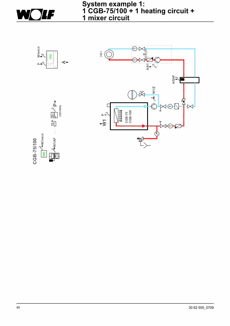
System example 1: 1 CGB-75/100 + 1 heating circuit + 1 mixer circuit
4130 62 555_0709
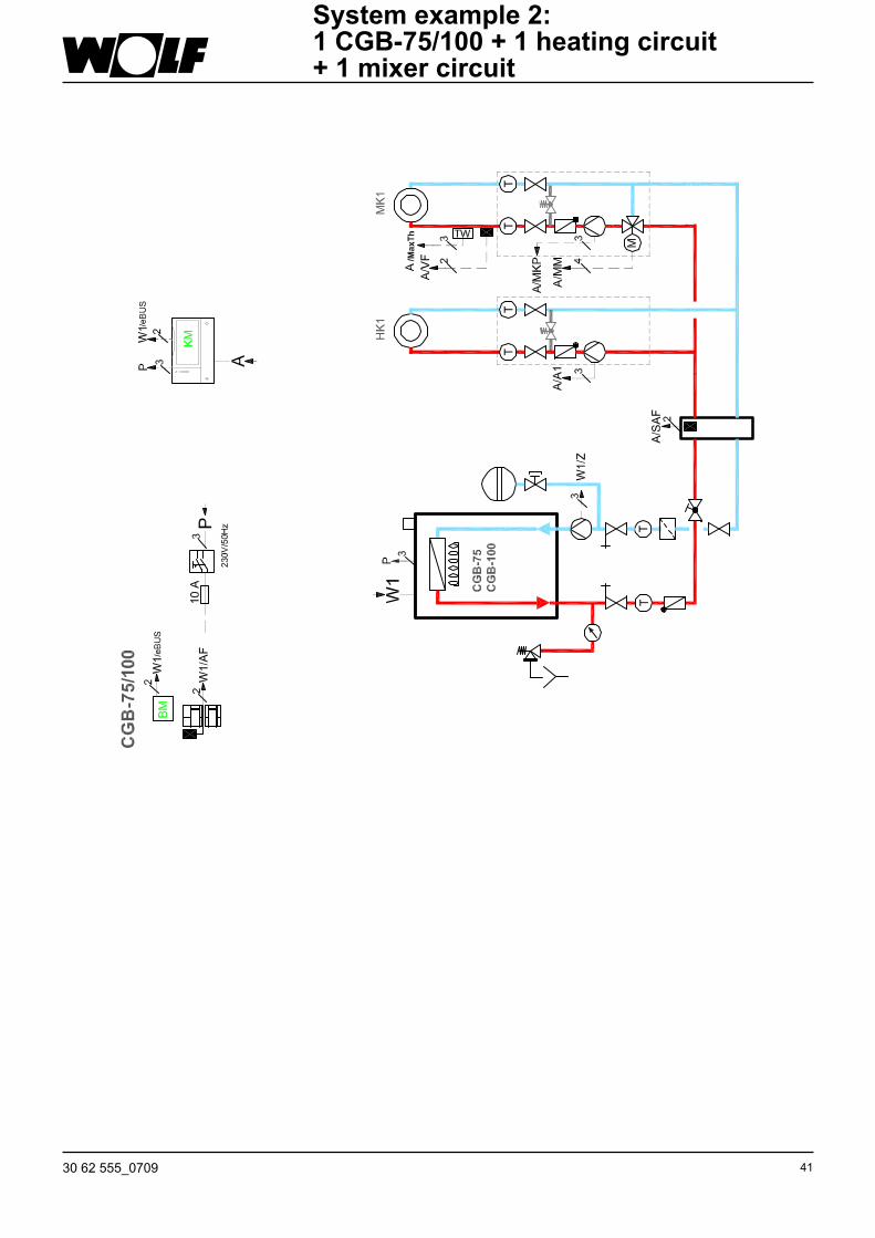
System example 2: 1 CGB-75/100 + 1 heating circuit + 1 mixer circuit
System example 1: 1 CGB-75/100 + 1 heating circuit + 1 mixer circuit

42 30 62 555_0709
System example 3:1 CGB-75/100 + 1 heating circuit + 3-6 mixer circuits + 1 cylinder

4330 62 555_0709
System example 4:1 CGB-75/100 + 1 heating circuit + 1 mixer circuit + 1 cylinder
44 30 62 555_0709
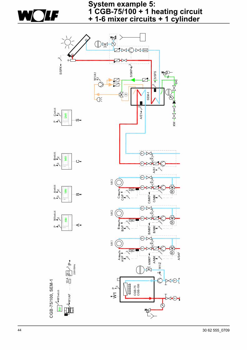
System example 5:1 CGB-75/100 + 1 heating circuit + 1-6 mixer circuits + 1 cylinder
4530 62 555_0709
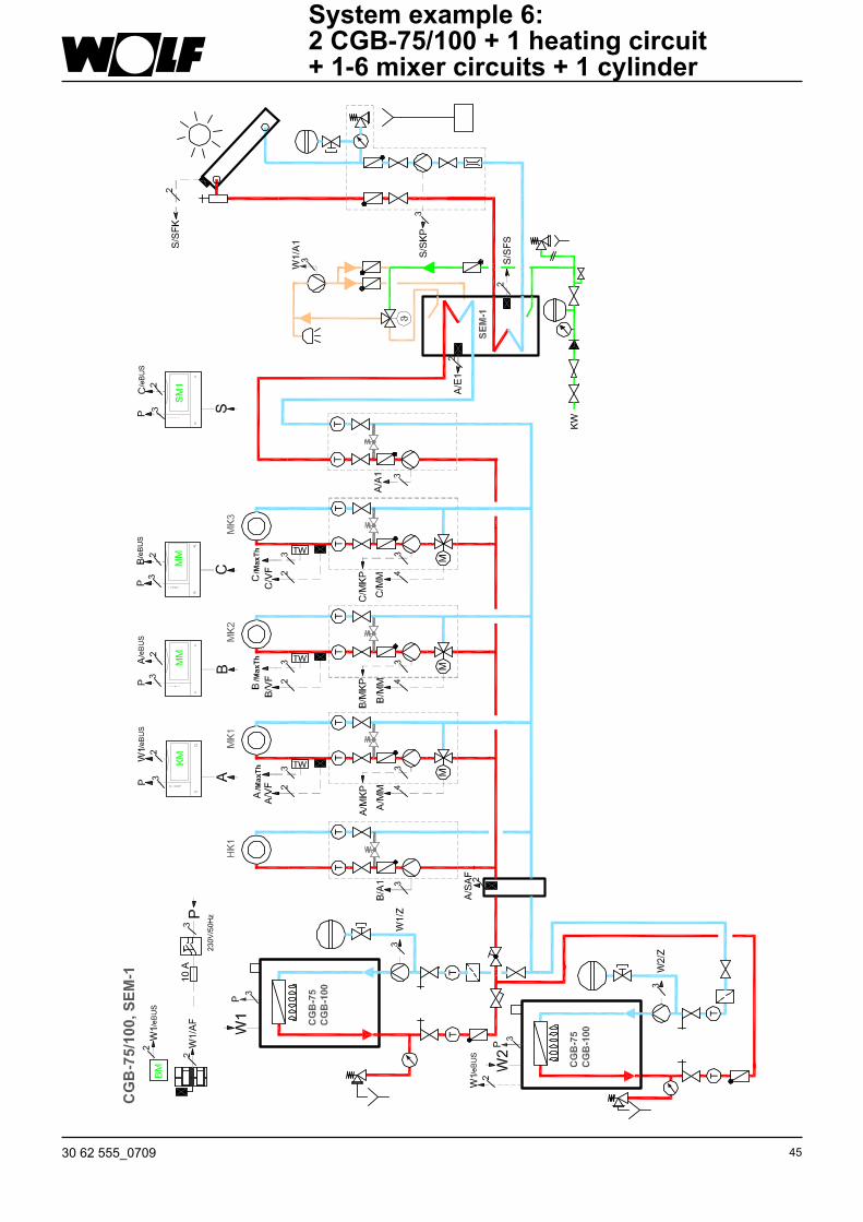
System example 6:2 CGB-75/100 + 1 heating circuit + 1-6 mixer circuits + 1 cylinder

46 30 62 555_0709
Key to system examplesWiring arrow with letters (e.g. "A"): Wiring is carried out to the relevant control unit (e.g. "A")OS ........ Outside temperature sensorATF ....... Flue gas temperature sensorDK......... Unmixed heating circuitE Bus .... e-BUS connectionFB ......... Remote controlFK ......... Remote contactFK_ ....... Output stage for convector heaterFU ......... Radio clock moduleFUA....... Radio clock module with outside temperature sensorHC ........ Heating circuitKF ......... Boiler sensorKKP ...... Boiler circuit pumpScS ...... Solar panel buffer sensorKTR ...... Boiler thermostatSPFS .... Solar panel flow sensorLP ......... Cylinder primary pumpLH ......... Convector heatermc ........ Mixer circuitm ........... MotorRAH ...... Return temperature raising, wood boilerRLF ....... Return sensorRT ......... Room thermostatSF ......... Cylinder sensorSFK....... Solar sensor - collectorSFS....... Solar sensor - cylinderSP ......... CylinderSPG ...... Solar pump assemblySTB....... Safety temperature controllerSTR ...... DHW cylinder thermostatSVF....... Total flow sensorTW ........ Temperature limiterUV......... Diverter valveVA ......... Variable outputVI .......... Variable inputVF ......... Flow sensorZP ......... DHW circulation pump
Key to the system examples

4730 62 555_0709
Parts list for the system examples
No. Description
01 CGB-75 CGB-100
06 Programming module BM
10 mixer module mm
11 Solar module SM1
13 Cascade module Km
20 Low loss header
48 30 62 555_0709
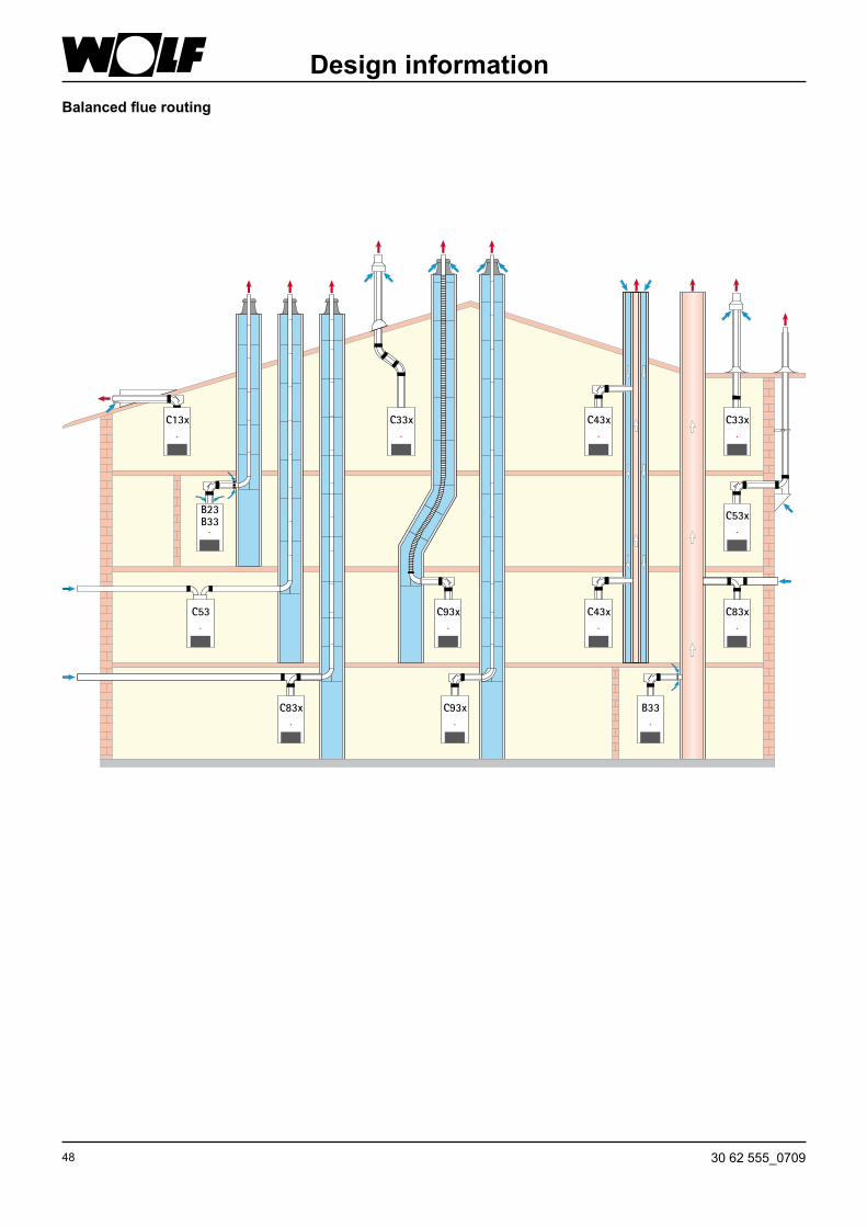
Balanced flue routing
Design information
B23B33
C53 C93x C43x C83x
C53x
C33xI IIII IIIII IIIII IIII IIIII IIII IIIII IIIII IIII IIIII IIIII IIII IIIII IIII IIIII IIIII IIII IIIII IIIII IIII IIIII IIIII
I IIIII IIII IIIII IIIII III
IIIIIIIIIIII
II
II
II
IIII
I
III
IIIIII
IIII
IIIIIIIIIIIII
C33x C43x
C83x C93x B33
C13x
4930 62 555_0709
Design informationBalanced flue routing
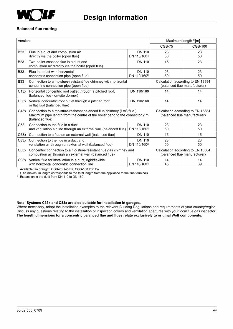
Note: Systems C33x and C83x are also suitable for installation in garages.Where necessary, adapt the installation examples to the relevant Building Regulations and requirements of your country/region. Discuss any questions relating to the installation of inspection covers and ventilation apertures with your local flue gas inspector.The length dimensions for a concentric balanced flue and flues relate exclusively to original Wolf components.
Versions Maximum length 1) [m]CGB-75 CGB-100
B23 Flue in a duct and combustion airdirectly via the boiler (open flue)
DN 110DN 110/1602)
2350
2350
B23 Two-boiler cascade flue in a duct andcombustion air directly via the boiler (open flue)
DN 110 45 23
B33 Flue in a duct with horizontalconcentric connection pipe (open flue)
DN 110DN 110/1602)
2350
2350
B33 Connection to a moisture-resistant flue chimney with horizontalconcentric connection pipe (open flue)
Calculation according to EN 13384 (balanced flue manufacturer)
C13x Horizontal concentric roof outlet through a pitched roof,(balanced flue - on-site dormer)
DN 110/160 14 14
C33x Vertical concentric roof outlet through a pitched roofor flat roof (balanced flue)
DN 110/160 14 14
C43x Connection to a moisture-resistant balanced flue chimney (LAS flue )Maximum pipe length from the centre of the boiler bend to the connector 2 m (balanced flue)
Calculation according to EN 13384 (balanced flue manufacturer)
c53 Connection to the flue in a ductand ventilation air line through an external wall (balanced flue)
DN 110DN 110/1602)
2350
2350
C53x Connection to a flue on an external wall (balanced flue) DN 110 15 15C83x Connection to the flue in a duct and
ventilation air through an external wall (balanced flue)DN 110
DN 110/1602)2350
2350
C83x Concentric connection to a moisture-resistant flue gas chimney and combustion air through an external wall (balanced flue)
Calculation according to EN 13384 (balanced flue manufacturer)
C93x Vertical flue for installation in a duct, rigid/flexiblewith horizontal concentric connection line
DN 110DN 110/1602)
1445
14 39
1) Available fan draught: CGB-75 145 Pa, CGB-100 200 Pa (The maximum length corresponds to the total length from the appliance to the flue terminal) 2) Expansion in the duct from DN 110 to DN 160
50 30 62 555_0709
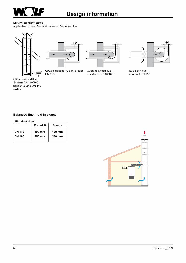
Minimum duct sizesapplicable to open flue and balanced flue operation
Design information
Balanced flue, rigid in a duct
Min. duct sizesRound Ø Square
DN 110DN 160
190 mm 250 mm
170 mm 230 mm
4
>20 >305
C93x balanced flue in a duct DN 110
C33x balanced flue in a duct DN 110/160
B33 open flue in a duct DN 110
C93 x balanced flueSystem DN 110/160 horizontal and DN 110 vertical
B33
5130 62 555_0709
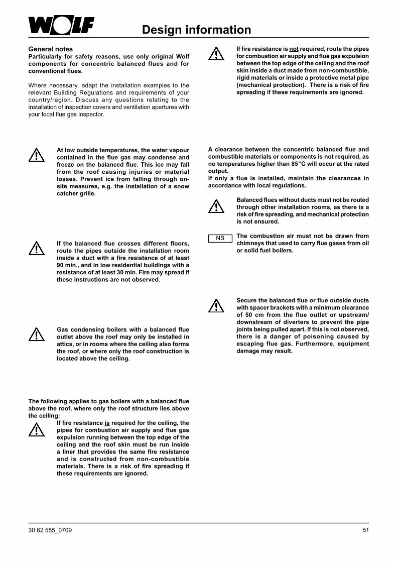
Design informationGeneral notesParticularly for safety reasons, use only original Wolf components for concentric balanced flues and for conventional flues.
Where necessary, adapt the installation examples to the relevant Building Regulations and requirements of your country/region. Discuss any questions relating to the installation of inspection covers and ventilation apertures with your local flue gas inspector.
At low outside temperatures, the water vapour contained in the flue gas may condense and freeze on the balanced flue. This ice may fall from the roof causing injuries or material losses. Prevent ice from falling through on-site measures, e.g. the installation of a snow catcher grille.
If the balanced flue crosses different floors, route the pipes outside the installation room inside a duct with a fire resistance of at least 90 min., and in low residential buildings with a resistance of at least 30 min. Fire may spread if these instructions are not observed.
Gas condensing boilers with a balanced flue outlet above the roof may only be installed in attics, or in rooms where the ceiling also forms the roof, or where only the roof construction is located above the ceiling.
The following applies to gas boilers with a balanced flue above the roof, where only the roof structure lies above the ceiling: If fire resistance is required for the ceiling, the
pipes for combustion air supply and flue gas expulsion running between the top edge of the ceiling and the roof skin must be run inside a liner that provides the same fire resistance and is constructed from non-combustible materials. There is a risk of fire spreading if these requirements are ignored.
If fire resistance is not required, route the pipes for combustion air supply and flue gas expulsion between the top edge of the ceiling and the roof skin inside a duct made from non-combustible, rigid materials or inside a protective metal pipe (mechanical protection). There is a risk of fire spreading if these requirements are ignored.
Secure the balanced flue or flue outside ducts with spacer brackets with a minimum clearance of 50 cm from the flue outlet or upstream/downstream of diverters to prevent the pipe joints being pulled apart. If this is not observed, there is a danger of poisoning caused by escaping flue gas. Furthermore, equipment damage may result.
A clearance between the concentric balanced flue and combustible materials or components is not required, as no temperatures higher than 85 °C will occur at the rated output.If only a flue is installed, maintain the clearances in accordance with local regulations.
Balanced flues without ducts must not be routed through other installation rooms, as there is a risk of fire spreading, and mechanical protection is not ensured.
The combustion air must not be drawn from chimneys that used to carry flue gases from oil or solid fuel boilers.
NB

52 30 62 555_0709
Flue gas temperature limiterThe electronic flue gas temperature limiter switches the oil condensing boiler off when the flue gas temperature exceeds 110 °C.
The boiler restarts when the reset button is pressed.
Calculating the balanced flue lengthThe calculated length of the balanced flue system or the flue is derived from the straight pipe length and the length of the pipe bends. In this calculation, a 90° bend or a 87° tee is calculated as being 2 m and a 45° bend as being 1 m.
Between the flue terminal and the roof surface, as of a rated output of 50 kW, there must be a clearance of at least 1.0 m.
Example:Length of straight balanced flue 1.5 m Inspection tee 87° = 2 m
2 x 45° bends = 2 x 1 m L = 1.5 m + 1 x 2 m + 2 x 1 m
L = 5.5 m
Design information
Component Calculated length
87° bend 2 m
45° bend 1 m
Tee 87° with
inspection aperture
2 m
Straight pipe Subject to length
Table: Pipe length calculation
Connection to the balanced flueThe unobstructed cross-section of flues must be able to be inspected. Therefore, install an inspection and/or test aperture inside the boiler room; agree suitable arrangements with your local flue gas inspector.
Flue connections are created using couplings and gaskets. Always arrange couplings against the direction of the condensate flow.
The balanced flue should be installed with a slope of at least 3° (6 cm/m) to the gas condensing boiler. Install spacer clamps to secure the location (see installation example).In the worst case scenario, a lesser slope of the balanced flue may lead to corrosion or operating faults.
Generally bevel or deburr trimmed flues to ensure a gas tight installation of pipe joints. Ensure that gaskets are correctly fitted. Remove all contamination prior to installation - never fit faulty parts.
NB
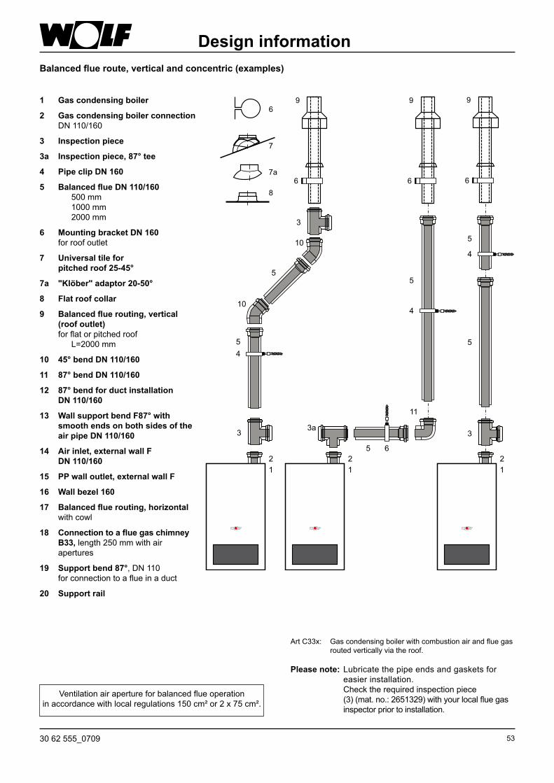
5330 62 555_0709
Balanced flue route, vertical and concentric (examples)
1 Gas condensing boiler
2 Gas condensing boiler connection DN 110/160
3 Inspection piece
3a Inspection piece, 87° tee
4 Pipe clip DN 160
5 Balanced flue DN 110/160 500 mm 1000 mm 2000 mm
6 Mounting bracket DN 160 for roof outlet
7 Universal tile for pitched roof 25-45°
7a "Klöber" adaptor 20-50°
8 Flat roof collar
9 Balanced flue routing, vertical (roof outlet) for flat or pitched roof L=2000 mm
10 45° bend DN 110/160
11 87° bend DN 110/160
12 87° bend for duct installation DN 110/160
13 Wall support bend F87° with smooth ends on both sides of the air pipe DN 110/160
14 Air inlet, external wall F DN 110/160
15 PP wall outlet, external wall F
16 Wall bezel 160
17 Balanced flue routing, horizontal with cowl
18 Connection to a flue gas chimney B33, length 250 mm with air apertures
19 Support bend 87°, DN 110 for connection to a flue in a duct
20 Support rail
Please note: Lubricate the pipe ends and gaskets for easier installation. Check the required inspection piece (3) (mat. no.: 2651329) with your local flue gas inspector prior to installation.
Art C33x: Gas condensing boiler with combustion air and flue gas routed vertically via the roof.
Design information
Ventilation air aperture for balanced flue operationin accordance with local regulations 150 cm² or 2 x 75 cm².
7
7a
6
8
5 6
11
3
3
3
54
4
4
5
5
5
5
10
10
21
21
21
3a
6
9
6
9
6
9

54 30 62 555_0709
Horizontal concentric balanced flue C13x, C83x and B33 and flue on an external wall C53x (examples)
Design information
2618 26 5
19
20164521
3a
4
16 16
Ventilation air aperture in balanced flue operation150 cm² or 2 x 75 cm².
C83 x
Install the horizontal flue with a slope of approx. 3° (6 cm/m) towards the boiler. Route the horizontal air supply with a 3° slope towards the outside – install the air inlet with a cowl; permissible wind pressure at the air inlet 90 Pa. The appliance will not operate with higher wind pressure. Downstream of the support bend, the flue Ø 110 mm or the flexible flue DN 110 can be routed in a duct.
21 Flue pipe DN 110 500 mm 1000 mm 2000 mm
22 Bend 87° DN 10023 Spacer24 Cowl25 Air inlet pipe Ø 110 mm26 Air pipe Ø 160 mm
without internal pipe
4
4 1616
5
5
55
45
16
180
>40017
2 2
1
2
3a
3a
3a
13
5
15
5
13
5
14
15
5
19
2016
24
15
C13 x C53 x B33
Horizontal balanced flue routing through a pitched roof
Flue on an external wall
(where required)
120 mm Ø opening in the chimney side. Install the flue airtight into the chimney side.
Dormer(on site)
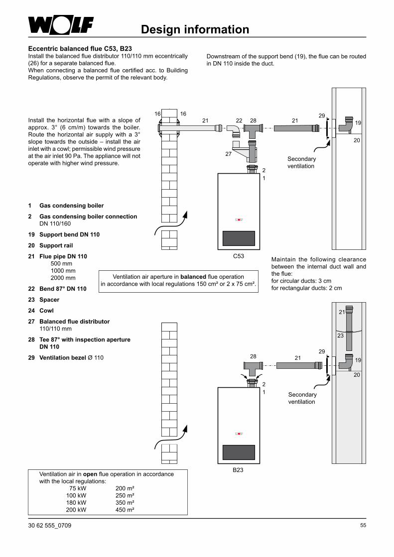
5530 62 555_0709
Eccentric balanced flue C53, B23Install the balanced flue distributor 110/110 mm eccentrically (26) for a separate balanced flue.When connecting a balanced flue certified acc. to Building Regulations, observe the permit of the relevant body.
1 Gas condensing boiler
2 Gas condensing boiler connection DN 110/160
19 Support bend DN 110
20 Support rail
21 Flue pipe DN 110 500 mm 1000 mm 2000 mm
22 Bend 87° DN 110
23 Spacer
24 Cowl
27 Balanced flue distributor 110/110 mm
28 Tee 87° with inspection aperture DN 110
29 Ventilation bezel Ø 110
Downstream of the support bend (19), the flue can be routed in DN 110 inside the duct.
Install the horizontal flue with a slope of approx. 3° (6 cm/m) towards the boiler. Route the horizontal air supply with a 3° slope towards the outside – install the air inlet with a cowl; permissible wind pressure at the air inlet 90 Pa. The appliance will not operate with higher wind pressure.
Maintain the following clearance between the internal duct wall and the flue:for circular ducts: 3 cmfor rectangular ducts: 2 cm
Design information
Secondary ventilation
B23
Secondary ventilation
c53
Ventilation air aperture in balanced flue operationin accordance with local regulations 150 cm² or 2 x 75 cm².
Ventilation air in open flue operation in accordance with the local regulations: 75 kW 200 m² 100 kW 250 m² 180 kW 350 m² 200 kW 450 m²

56 30 62 555_0709
Design informationSupplementary installation notes
Determine distance A. Length of balanced flue (5) always approx. 100 mm longer than distance A. Always trim the flue on the smooth side, never on the coupling side. Chamfer the flue after trimming.
Distan
ce A
Offset
Bends Offset87° min. 270 mm45° min. 106 mm
Distance A
Distance A
To check the balanced flue, undo and remove the cover of the inspection piece (3).
Inspection piece (3)
Please note: Lubricate all balanced flue joints prior to installation, e.g. with a soapy solution, or coat lightly with suitable grease (mat. no. 2651329).
Install all horizontal balanced flues with > 3° slope (6 cm/m) towards the boi ler. Any condensate must be returned to the boiler.Install the centring triangles near the end of the pipe.
180
I f requi red, a f lue p ipe expansion piece in a duct from DN 110 to DN 160 can be fitted at the support bend. Ø 160
Flat roof: Affix the ceiling outlet approx. Ø 170 mm (8) deep into the roof cover.
Pitched roof: At (7, 7a), observe the installation instructions on the cowl regarding roof pitches.
If an inspection aperture is required for the balanced flue, insert a balanced flue with inspection aperture (3) (200 mm length).
Insert the roof outlet (9) from above through the roof and secure vertically with (6) to a rafter or brickwork.Install the roof outlet only in its original condition.Modifications are not permissible.
7
650
550-
1050
1250
1750
-230
0
7
7a
6
8
9

5730 62 555_0709
The following applies in accordance with local regulations:
Connection to a moisture-resistant balanced flue chimney (LAS), flue gas chimney or flue gas systemChimneys and flue gas systems must be certified for combustion equipment in accordance with local Building Regulations (CE certification). Sizing via calculation tables subject to flue gas category. In addition to the boiler connection bend or tee piece, up to two 90° diversions may be installed. Operation with positive pressure may require an appropriate permit.
Connection to a moisture-resistant balanced flue chimney type C43xStraight balanced flues may be up to 2.0 m long, when installing the system in a balanced flue chimney. In addition to the boiler connection bend, up to two 90° diverters may be installed.
The balanced flue chimney (LAS) must be inspected by the relevant authority and approved for pressurised condensing operation.
Connection to a moisture-resistant flue gas chimney or a flue system type B33 for open flue operationStraight balanced flues must be no longer than 2 m when connecting the system to a flue gas chimney. In addition to the boiler connection bend, up to two 90° diverters may be installed.
The flue gas chimney must be inspected by the relevant authority and must be approved for condensing operation.
If necessary, the flue outlet should be obtained from the chimney manufacturer.
The air vents to the boiler room must be free from obstruction.
Connection to a moisture-resistant flue type B23 for open flue operationThe straight, horizontal flue must not be longer than 3 m.
In addition to the boiler connection bend, up to two 90° diversions may be installed into the horizontal flue.
For this version, observe the ventilation requirements for boiler rooms acc. to local regulations.
Design information
Connection to a moisture-resistant flue type C53, C83x for balanced flue operationThe straight, horizontal flue must not be longer than 3 m. For horizontal air supply pipes, a maximum length of 3 m is recommended. Observe special requirements for flues that are not surrounded by combustion air acc. to local regulations or all locally applicable combustion orders.
Connection to a combustion air and flue system type C63x that is not tested together with the gas combustion equipmentOriginal Wolf components are designed for long-term use, are designated with the DVGW quality seal and are matched for use with Wolf gas condensing boilers. When using CE-designated third party equipment, the installer is responsible for the correct sizing and perfect function of such systems. Faults, material losses and injuries resulting from incorrect pipe lengths, excessive pressure drop, premature wear with escaping flue gas and condensate or incorrect function, e.g. through components working themselves loose, are excluded from our warranty if non-CE-approved third party equipment is used. Straight balanced flues must be no longer than 2 m, when connecting the system to a combustion air supply and a separate flue.
In addition to the boiler connection bend, up to two 90° diverters may be installed.
The chimney must be free from contamination if the combustion air is drawn from the chimney.
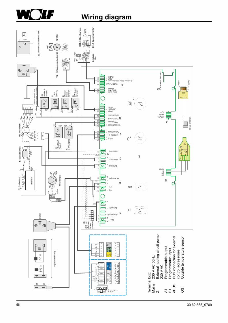
58 30 62 555_0709
Wiring diagram
Term
inal
box
:M
ains
23
0 V
AC
50H
zZ
Ext
erna
l hea
ting
circ
uit p
ump
230
V A
CA
1 P
rogr
amm
able
out
put
E1
Pro
gram
mab
le in
put
eBU
S
BU
S c
onne
ctio
n fo
r ext
erna
l
cont
rol a
cces
sorie
sO
S
Out
side
tem
pera
ture
sen
sor

5930 62 555_0709
Type CGB-75 CGB-100Rated output at 80/60 °C kW 70.1 91.9 2)
Rated output at 50/30 °C kW 75.8 98.8Rated heat input kW 71.5 94Lowest output (modulating at 80/60) kW 18.2 18.2Lowest output (modulating at 50/30) kW 19.6 19.6Lowest heat input (modulating) kW 18.5 18.5External diameter, heating flow G 1½" 1½"External diameter, heating return G 1½" 1½"Drain outlet (condensate) 1" 1"Gas connection R ¾" ¾"Balanced flue connection mm 110/160 110/160Appliance dimensions HxWxD mm 1020x565x548 1020x565x548Balanced flue routing type B23, B33, B23, B33,
C13, C13x C13, C13xC33, C33x C33, C33xC43, C43x C43, C43xC53, C53x C53, C53xC63, C63x C63, C63xC83, C83x C83, C83xC93, C93x C93, C93x
Gas category: II2H3P II2H3P
Gas supply details: Natural gas H (Hi = 9.5 kWh/m³ = 34.2 MJ/m³) m³/h 7.77 10.03 LPG P (Hi = 12.8 kWh/kg = 46.1 MJ/kg) kg/h 5.76 7.44Gas supply pressure: Natural gas mbar 20 20 LPG mbar 37/50 37/50Flow temperature, factory setting °C 80 80Maximum flow temperature °C 90 90Max. overall pressure, heating bar 6 6Heating water heat exchanger water content l 10 10DHW temperature range (adjustable) °C 15-65 15-65Heating water pressure drop at 20 K spread mbar 70 120Rated output: Flue gas mass flow rate g/s 33.7 43.5 Flue gas temperature 50/30 - 80/60 °C 48-72 53-78 Available gas fan draught Pa 145 200Lowest heat input: Flue gas mass flow rate g/s 8.9 8.9 Flue gas temperature 50/30 - 80/60 °C 36-60 36-60 Available gas fan draught Pa 12 12Flue gas group according to DVGW G 635 G52 G52NOx category 5 5Electrical connection V~/Hz 230/50 230/50Integral fuse (medium slow) A 3.15 3.15Power consumption W 75 130Protection IPX 4D IPX 4DTotal weight (dry) kg 92 92Condensate volume at 40/30 °C l/h 7.1 9.8Condensate pH value approx. 4 approx. 4cE ID 0085BR0164ÖVGW quality symbol G 2,775"
Specification

60 30 62 555_0709
TroubleshootingAny faults will be displayed as fault codes by Wolf controllers with eBUS capability. To these faults, cause and remedy may be allocated using the following table. This table is designed to allow your local heating contractor to trace the fault more easily.
Fault code
Fault Cause Remedy
1 TBV excess temperature Water pressure too low
The flow temperature has exceeded the limit for the TBV shutdown temperature, or the heat exchanger is extremely dirty, or the water pressure switch switches off at a pressure < 1.0 bar
Check system pressure; check heating circuit pump; vent the system; press reset button; clean heat exchanger; check TB combustion chamber; increase system pressure; check dirt filter
4 No flame established No flame established during burner start Check gas supply line, open gas tap if necessary Check ignition electrode and ignition cable Press reset button
5 Flame failure during operation
Flame failure within 15 s after flame recognition
Check CO2 values Check ionisation electrode and cable Press reset button
6 TW excess temperature The flow/return temperature has exceeded the limit for the TW shutdown temperature
Check the system pressure. Vent the system Set the pump to stage 2 or 3
7 TBA excess temperature Overpressure in the flue gas system
The flue gas temperature has exceeded the limit for the TBA shutdown temperature Flue gas system is blocked Ventilation air is blocked
Clean the heat exchanger Check the flue gas system Check the ventilation air
11 Flame pretence A flame is recognised before the burner starts Press reset12 Faulty flow sensor
Gas pressure too low
The sensor for the flow temperature or the cable is faulty, or the gas pressure < than the selected value at the gas governor (only displayed after 15 min)
Check lead Check flow sensor Check gas pressure Check gas governor (accessory)
14 Cylinder sensor faulty DHW temperature sensor or lead faulty Check sensor and lead15 Faulty outside
temperature sensorThe outside temperature sensor or lead is faulty Check lead
Check outside temperature sensor16 Return sensor faulty The return temperature sensor or lead is faulty Check lead
Check return sensor20 Fault, gas valve "1" A flame is recognised for 15 seconds after burner
operation, even though gas valve 1 has received a shutdown command
Replace the gas combination valve
21 Fault, gas valve "2" A flame is recognised for 15 seconds after burner operation, even though gas valve 2 has received a shutdown command
Replace the gas combination valve
24 Gas fan fault The gas fan does not reach the required pre-purging speed
Check the gas fan supply cable and the gas fan. Press reset
25 Gas fan fault The gas fan does not reach the ignition speed Check the gas fan supply cable and the gas fan. Press reset
26 Gas fan fault The gas fan does not stop Check the gas fan supply cable and the gas fan. Press reset
30 CRC fault, gas condensing boiler
The EEPROM record "Gas condensing boiler" is invalid Switch the power supply OFF and ON If unsuccessful, replace the control unit PCB
31 CRC fault burner The EEPROM record "Burner" is invalid Switch the power supply OFF and ON If unsuccessful, replace the control unit PCB
32 Fault in 24 V AC supply 24 V AC supply outside the permissible range (e.g. short circuit)
Check gas fan
33 CRC fault, default values The EEPROM record "Master reset" is invalid Replace the control unit PCB34 CRC fault, BCC Faulty boiler coding card Replace boiler coding card

6130 62 555_0709
35 BCC missing Boiler coding card was removed Fit the correct boiler coding card36 CRC fault, BCC Faulty boiler coding card Replace boiler coding card37 Incorrect BCC The boiler coding card is incompatible with the control
unit PCBFit the correct boiler coding card
38 BCC no. invalid Faulty boiler coding card Replace boiler coding card39 BCC system error Faulty boiler coding card Replace boiler coding card41 Flow monitoring Return temperature > Flow + 25 K Vent heating system, check system pressure
Check heating circuit pump50 Activation of boiler
coding cardThe boiler coding card must be enabled Press reset 2 x
52 Activation of boiler coding card
The boiler coding card must be enabled Press reset 2 x
60 Ionisation current fluctuates
The siphon is blocked, or the flue gas system is blocked, severe storm
Clean siphon, check flue gas system, check ventilation air, check monitoring electrode
61 Ionisation current fails Poor gas quality, monitoring electrode faulty, severe storm
Check monitoring electrode and cable
LED constantly red Ionisation cable shorted out or ionisation electrode earthed (casing)
Check ionisation cable and position of electrode to burner. Press reset
Troubleshooting
Fault code
Fault Cause Remedy

62 30 62 555_0709
Notes

6330 62 555_0709
Notes

Dr. Fritz HilleTechnical Director
Gerdewan JacobsTechnical Manager
EC declaration of conformityHiermit erklären wir, dass das Wolf-Gas-Brennwerttherme sowie die Wolf-Gasheizkessel dem Baumuster entsprechen, wie es in der EG-Baumusterprüfbescheinigung beschrieben ist, und dass sie den für sie geltenden Anforderungen der Gasgeräterichtlinie 90/396/EWG vom 29.06.1990 genügen.
EC Declaration of ConformityWe herewith declare, that Wolf wall mounted gas appliances as well as Wolf gas boilers correspond to the type described in the EC Type Examination Certificate, and that they fulfil the valid requirements according to the Gas Appliance Directive 90/396/EEC dd. 1990/06/29.
Déclaration de conformité au modèle type CECi-joint, nous confirmons, que les chaudières murales à gaz Wolf et les chaudières a gaz Wolf sont conformes aux modèles type CE, et qu’elles correspondent aux exigences fondamentales en vigueur de la directive du 29-06-1990 par rapport aux installations alimentées de gaz (90/396/CEE).
Dichiarazione di conformita campione di costruzione - EG Con la presente dichiariamo che le nostre caldaie Murali a Gas Wolf e le caldaie a Gas Wolf corrispondono al e campioni di costruzione, come sono descritte nel certificato di collaudo EG „campione di costruzione“ e che esse soddisfano le disposizioni in vigore nella normativa: 90/396/EWG apparecchiature a Gas.
EG-konformiteitsverklaring Hierbij verklaren wij dat de Wolf gaswandketels alsmede de Wolf atmosferische staande gasketels gelijkwaardig zijn aan het model, zoals omschreven in het EG-keuringscertificaat, en dat deze aan de van toepassing zijnde eisen van de EG-richtlijn 90/396/EWG (Gastoestellen) d. d. 29.06.90 voldoen.
Declaración a la conformidad del tipo - CE Por la presente declaramos que las calderas murales Wolf al igual que las calderas atmosfericas a gas corresponden a la certificacion CE y cumplen la directiva de gas 90/396/CEE del 29.06.1990.
Wolf GmbHIndustriestraße 1D-84048 Mainburg