installation instructions - boiler service | plumbers … the instructions and recommendations in...
TRANSCRIPT

InstallationInstructionsType C BoilersG.C.N: 47-116-14
47-116-15LEAVE THESE INSTRUCTIONSWITH THE END-USER
Country of destination: GB

2
TABLE OF CONTENTS 1. GENERAL INFORMATION
1.1 GENERAL INSTRUCTIONS
1.2 OVERALL VIEW
2. INSTALLATION
2.1 REFERENCE STANDARDS
2.2 SITING THE APPLIANCE
2.3 OVERALL DIMENSIONS
2.4 CLEARANCES
2.5 MOUNTING THE APPLIANCE
2.6 ELECTRICAL CONNECTION
2.7 GAS CONNECTION
2.8 WATER CONNECTIONS
2.9 FLUE CONNECTION
2.10 ROOM THERMOSTAT CONNECTION
2.11 ELECTRICAL/SYSTEM DIAGRAMS
2.12 WATER CIRCUIT DIAGRAMS
3. COMMISSIONING
3.1 INITIAL PREPARATION
3.2 CONTROL PANEL
3.3 REMOVING THE FRONT PANEL
3.4 INITIAL START UP
3.5 OPERATIONAL ADJUSTMENTS
3.6 COMBUSTION ANALYSIS
3.7 FUME DISCHARGE MONITORING
3.8 BOILER SAFETY SYSTEMS
3.9 DRAINING THE SYSTEM
4. GAS ADJUSTMENTS
GAS ADJUSTMENT TABLE
4.1 CHANGING THE TYPE OF GAS
5. MAINTENANCE
6. MISCELLANEOUS
6.1 WIRING DIAGRAM FOR TWO HEATING ZONES
6.2 WIRING DIAGRAM FOR CONNECTION TO AN ARISTON UNVENTED CYLINDER
7. TECHNICAL INFORMATION

This manual is an integral and essential part of the product. It should be keptwith the appliance so that it can be consulted by the user and our authorisedpersonnel.
Please carefully read the instructionsand notices about the unit contained inthis manual, as they provide importantinformation regarding the safeinstallation, use and maintenance ofthe product.
For operating instructions pleaseconsult the separate User’s Manual.
Read the instructions and recommendations in these Installation Instructionscarefully to ensure proper installation, use and maintenance of the appliance.
Keep this manual in a safe place. You may need it for your own reference whileour Servicing Centre technicians or your installer may need to consult it in thefuture.
This is a combined appliance for the production of central heating (C.H.) anddomestic hot water (D.H.W.).
This appliance must be used only for the purpose for which it is designed.The manufacturer declines all liability for damage caused by improper ornegligent use.
No asbestos or other hazardous materials have been used in the fabrication ofthis product.
Before connecting the appliance, check that the information shown on the dataplate and the table on pages 4-5 comply with the electric, water and gas mainsof the property.You will find the data plate on the reverse of the control panel.The gas with which this appliance operates is also shown on the label at thebottom of the boiler.
Do not install this appliance in a damp environment or close to equipmentwhich spray water or other liquids.Do not place objects on the appliance.Do not allow children or inexperienced persons to use the appliance withoutsupervision.
If you smell gas in the room, do not turn on light switches, use the telephone orany other object which might cause sparks.Open doors and windows immediately to ventilate the room.Shut the gas mains tap (on the gas meter) or the valve of the gas cylinder andcall your Gas Supplier immediately.If you are going away for a long period of time, remember to shut the mains gastap or the gas cylinder valve.
Always disconnect the appliance either by unplugging it from the mains orturning off the mains switch before cleaning the appliance or carrying outmaintenance.
In the case of faults or failure, switch off the appliance and turn off the gastap. Do not tamper with the appliance.For repairs, call your local Authorised Servicing Centre and request the use oforiginal spare parts. For in-guarantee repairs contact MTS (GB) Limited.
Check the following at least once a year:1 - Check the seals for the water connections; replacement of any faulty seals.2 - Check the gas seals; replacement of any faulty gas seals.3 - Visual check of the entire unit.4 - Visual check of the combustion process or analysis of combustion by-
products (see section 3.6) and cleaning of the burner if needed.
1. GENERAL INFORMATION
3
1.1 GENERAL INSTRUCTIONS
CO034A
4
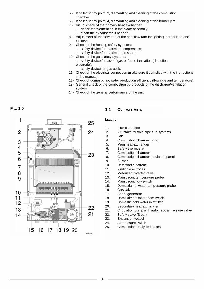
5 - If called for by point. 3, dismantling and cleaning of the combustionchamber.
6 - If called for by point. 4, dismantling and cleaning of the burner jets.7 - Visual check of the primary heat exchanger:
- check for overheating in the blade assembly;- clean the exhaust fan if needed.
8 - Adjustment of the flow rate of the gas: flow rate for lighting, partial load andfull load.
9 - Check of the heating safety systems:- safety device for maximum temperature;- safety device for maximum pressure.
10- Check of the gas safety systems:- safety device for lack of gas or flame ionisation (detection electrode);- safety device for gas cock.
11- Check of the electrical connection (make sure it complies with the instructionsin the manual).
12- Check of domestic hot water production efficiency (flow rate and temperature)13- General check of the combustion by-products of the discharge/ventilation
system.14- Check of the general performance of the unit.
LEGEND:
1. Flue connector2. Air intake for twin pipe flue systems3. Fan4. Combustion chamber hood5. Main heat exchanger6. Safety thermostat7. Combustion chamber8. Combustion chamber insulation panel9. Burner 10. Detection electrode11. Ignition electrodes12. Motorised diverter valve13. Main circuit temperature probe14. Main circuit flow switch 15. Domestic hot water temperature probe16. Gas valve17. Spark generator18. Domestic hot water flow switch19. Domestic cold water inlet filter20. Secondary heat exchanger21. Circulation pump with automatic air release valve22. Safety valve (3 bar)23. Expansion vessel24. Air pressure switch25. Combustion analysis intakes
1.2 OVERALL VIEWFIG. 1.0
IN013A

5
The technical information and instructions provided herein below areintended for the installer so that the unit may be installed correctly andsafely.
The installation and initial start up of the boiler must be by a CORGIApproved Installer in compliance with the installation standards currently ineffect, as well as with any and all local health and safety standards i.e..CORGI .
This appliance must be installed by a competent installer inaccordance with current Gas Safety (installation & use)Regulations.
The installation of this appliance must be in accordance with the relevantrequirements of the current Gas Safety (installation & use) Regulations, theLocal Building Regulations, the current I.E.E. Wiring Regulations, thebyelaws of the local water authority, and in Scotland, in accordance with theBuilding Standards (Scotland) Regulation and Health and Safety documentNo. 635 “Electricity at work regs. 1989”.Installation should also comply with the following British Standard Codes ofPractice:
The appliance may be installed in any room or indoor area, althoughparticular attention is drawn to the requirements of the current I.E.E. WiringRegulations, and in Scotland, the electrical provisions of the BuildingRegulations applicable in Scotland, with respect to the installation of thecombined appliance in a room containing a bath or shower.Where a room-sealed appliance is installed in a room containing a bathor shower the boiler and any electrical switch or appliance control,utilising mains electricity should be situated so that it cannot betouched by a person using the bath or shower.The location must permit adequate space for servicing and air circulationaround the appliance as indicated in paragraph 2.4.The location must permit the provision of an adequate flue and termination.For unusual locations special procedures may be necessary.BS 6798-1987 gives detailed guidance on this aspect.A compartment used to enclose the appliance must be designed specificallyfor this purpose. No specific ventilation requirements are needed for theinstallation within a cupboard.This appliance is not suitable for outdoor installation.
The type C appliances (in which the combustion circuit, air vent intakeand combustion chamber are air-tight with respect to the room inwhich the appliance is installed) can be installed in any type of room.There are no limitations with respect to ventilation and the volume of theroom itself. The boiler must be installed on a solid, permanent wall to preventaccess to the electrical parts (when live) through the aperture on the backframe.
2.1 REFERENCE STANDARDS
2. INSTALLATION
Low pressure pipes BS 6891 1988
Boilers of rated inputnot exceeding 60 kW BS 6798 1987
Forced circulation hot water system BS 5449 1990
Installation of gas hot watersupplies for domestic purposes
( 2nd family gases) BS 5546 1990Flues BS 5440-1 1990
Air supply BS 5440-2 1989
2.2 SITING THE APPLIANCE
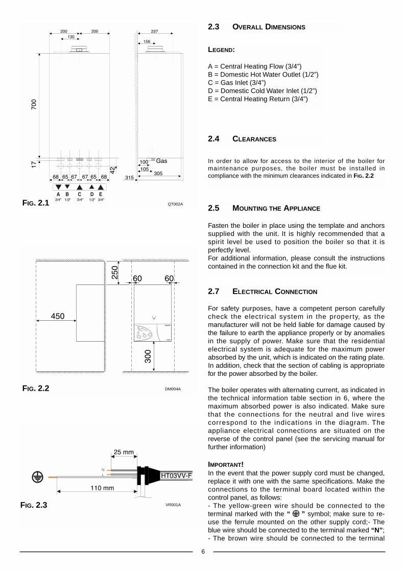
For safety purposes, have a competent person carefullycheck the electr ical system in the proper ty, as themanufacturer will not be held liable for damage caused bythe failure to earth the appliance properly or by anomaliesin the supply of power. Make sure that the residentialelectrical system is adequate for the maximum powerabsorbed by the unit, which is indicated on the rating plate.In addition, check that the section of cabling is appropriatefor the power absorbed by the boiler.
The boiler operates with alternating current, as indicated inthe technical information table section in 6, where themaximum absorbed power is also indicated. Make surethat the connections for the neutral and live wirescorrespond to the indications in the diagram. Theappliance electrical connections are situated on thereverse of the control panel (see the servicing manual forfurther information)
IMPORTANT!In the event that the power supply cord must be changed,replace it with one with the same specifications. Make theconnections to the terminal board located within thecontrol panel, as follows:- The yellow-green wire should be connected to theterminal marked with the “ ” symbol; make sure to re-use the ferrule mounted on the other supply cord;- Theblue wire should be connected to the terminal marked “N”;- The brown wire should be connected to the terminal
6
Fasten the boiler in place using the template and anchorssupplied with the unit. It is highly recommended that aspirit level be used to position the boiler so that it isperfectly level.For additional information, please consult the instructionscontained in the connection kit and the flue kit.
2.7 ELECTRICAL CONNECTION
2.5 MOUNTING THE APPLIANCE
LEGEND:
A = Central Heating Flow (3/4”)B = Domestic Hot Water Outlet (1/2”)C = Gas Inlet (3/4”)D = Domestic Cold Water Inlet (1/2”)E = Central Heating Return (3/4”)
2.3 OVERALL DIMENSIONS
In order to allow for access to the interior of the boiler formaintenance purposes, the boiler must be installed incompliance with the minimum clearances indicated in FIG. 2.2
2.4 CLEARANCES
FIG. 2.1
FIG. 2.2
FIG. 2.3
QT002A
DM004A
VR001A

VIEW OF THE BOILER CONNECTIONS
LEGEND:
A = Central Heating FlowB = Domestic Hot Water OutletC = Gas InletD = Domestic Cold Water InletE = Central Heating ReturnF = Safety Valve
CENTRAL HEATING
Detailed recommendations are given in BS 6798:1987 and BS 5449-1:1990,the following notes are given for general guidance.
2.9 WATER CONNECTIONS
2.8 GAS CONNECTION The local gas region contractor connects the gas meter to the service pipe.If the gas supply for the boiler serves other appliances ensure that anadequate supply is available both to the boiler and the other applianceswhen they are in use at the same time.Pipe work must be of an adequate size. Pipes of a smaller size than theboiler inlet connection should not be used.
7
marked “L”.Note: The diagrams for the electrical system are indicated in section 2.11.
Warning, this appliance must be earthed.External wiring to the appliance must be carried out by a qualified technicianand be in accordance with the current I.E.E. Regulations and applicablelocal regulations. The Genus range of boilers are supplied for connection toa 230 V~ 50 Hz supply.The supply must be fused at 3 A.The method of connection to the electricity supply must facilitate completeelectrical isolation of the appliance, by the use of a fused double poleisolator having a contact separation of at least 3 mm in all poles oralternatively, by means of a 3 A fused three pin plug and unswitchedshuttered socket outlet both complying with BS 1363.The point of connection to the Electricity supply must be readily accessibleand adjacent to the appliance unless the appliance is installed in a bathroomwhen this must be sited outside the bathroom.
FIG. 2.4
FIG. 2.5 KT002A
SC008A

8
PIPE WORK:Copper tubing to BS EN 1057:1996 is recommended for water pipes.Jointing should be either with capillary soldered or compression fittings.Where possible pipes should have a gradient to ensure air is carriednaturally to air release points and water flows naturally to drain taps.The appliance has a built-in automatic air release valve, however it shouldbe ensured as far as possible that the appliance heat exchanger is not anatural collecting point for air.Except where providing useful heat, pipes should be insulated to preventheat loss and avoid freezing.Particular attention should be paid to pipes passing through ventilatedspaces in roofs and under floors.BY-PASS:The appliance includes an automatic by-pass valve, which protects the mainheat exchanger in case of reduced or interrupted water circulation throughthe heating system, due to the closing of thermostatic valves or cock-typevalves within the system.SYSTEM DESIGN:This boiler is suitable only for sealed systems.Drain Cocks:These must be located in accessible positions to permit the draining of thewhole system. The taps must be at least 15mm nominal size andmanufactured in accordance with BS 2870:1980.SAFETY VALVE DISCHARGE:The discharge should terminate facing downward on the exterior of thebuilding in a position where discharging (possibly boiling water & steam) willnot create danger or nuisance, but in an easily visible position, and notcause damage to electrical components and wiring.The discharge must not be over an entrance or a window or any other typeof public access.AIR RELEASE POINTS:These must be fitted at all high points where air naturally collects and mustbe sited to facilitate complete filling of the system.The appliance has an integral sealed expansion vessel to accommodate theincrease of water value when the system is heated.It can accept up to 6 l (1.3 gal) of expansion water. If the heating circuit hasan unusually high water content, calculate the total expansion and add anadditional sealed expansion vessel with adequate capacity.MAINS WATER FEED - CENTRAL HEATING:There must be no direct connection to the mains water supply even througha non-return valve, without the approval of the Local Water Authority.FILLING:A temporary method for initially filling the system and replacing lost waterduring servicing in accordance with Water Supply Byelaw 14 must beprovided.
DOMESTIC WATER
The domestic water must be in accordance with the relevantrecommendation of BS 5546:1990. Copper tubing to BS EN 1057:1996 isrecommended for water carrying pipe work and must be used for pipe workcarrying drinking water.
RESIDUAL HEAD OF THE BOILER
VR003A
Ø 60/100 mm
FIG. 2.7
A
BC
D
E
F
G
J
K
HI
L
GF
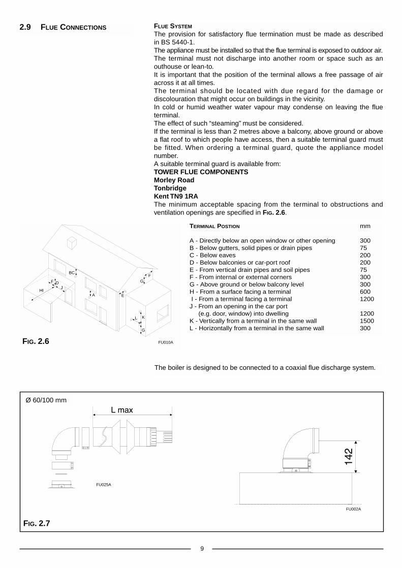
The boiler is designed to be connected to a coaxial flue discharge system.
9
2.9 FLUE CONNECTIONS FLUE SYSTEM
The provision for satisfactory flue termination must be made as describedin BS 5440-1.The appliance must be installed so that the flue terminal is exposed to outdoor air.The terminal must not discharge into another room or space such as anouthouse or lean-to.It is important that the position of the terminal allows a free passage of airacross it at all times.The terminal should be located with due regard for the damage ordiscolouration that might occur on buildings in the vicinity.In cold or humid weather water vapour may condense on leaving the flueterminal.The effect of such “steaming” must be considered.If the terminal is less than 2 metres above a balcony, above ground or abovea flat roof to which people have access, then a suitable terminal guard mustbe fitted. When ordering a terminal guard, quote the appliance modelnumber.A suitable terminal guard is available from:TOWER FLUE COMPONENTSMorley RoadTonbridgeKent TN9 1RAThe minimum acceptable spacing from the terminal to obstructions andventilation openings are specified in FIG. 2.6.
TERMINAL POSTION mm
A - Directly below an open window or other opening 300B - Below gutters, solid pipes or drain pipes 75C - Below eaves 200D - Below balconies or car-port roof 200E - From vertical drain pipes and soil pipes 75F - From internal or external corners 300G - Above ground or below balcony level 300H - From a surface facing a terminal 600I - From a terminal facing a terminal 1200J - From an opening in the car port
(e.g. door, window) into dwelling 1200K - Vertically from a terminal in the same wall 1500L - Horizontally from a terminal in the same wall 300
FIG. 2.6 FU010A
FU025A
FU002A
Ø 80 mm
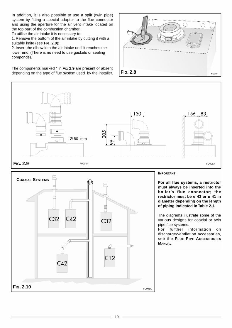
The components marked * in FIG 2.9 are present or absentdepending on the type of flue system used by the installer.
In addition, it is also possible to use a split (twin pipe)system by fitting a special adaptor to the flue connectorand using the aperture for the air vent intake located onthe top part of the combustion chamber.To utilise the air intake it is necessary to:1. Remove the bottom of the air intake by cutting it with asuitable knife (see FIG. 2.8);2. Insert the elbow into the air intake until it reaches thelower end. (There is no need to use gaskets or sealingcomponds).
10
IMPORTANT!
For all flue systems, a restrictormust always be inserted into theboiler’s flue connector; therestrictor must be ø 43 or ø 41 indiameter depending on the lengthof piping indicated in Table 2.1.
The diagrams illustrate some of thevarious designs for coaxial or twinpipe flue systems.For fur ther information ondischarge/ventilation accessories,see the FLUE PIPE ACCESSORIES
MANUAL.
COAXIAL SYSTEMS
FIG. 2.8
FIG. 2.9
FIG. 2.10
FU05A
FU004A FU006A
FU001A

ExhaustType
C12 (xy)
C32 (xy)
C42 (xy)
C52 (xy)
C82 (xy)
Restrictorø 43 mm
L max = 11.5 m
L max = 11,4 m
MaximumExtensionExhaust/Air
43 m
43 m
43 m
40 m
NORestrictor
L min = 11.5 m
L max = 43 m
L min = 11,4 m
L max = 40m
Risk of Condensation Forming
Twin PipeSystemsø 80/80
Piping not insulatedø 43 restrictor NO
4.3 m 6.9 m
4.3 m 6.9 m
Piping insulatedø 43 restrictor NO
NONE NONE
5,7 m 21,7 m
L = Sum of the total length of exhaust + air intake piping.
11
ExhaustType
C12 (xx)
C32 (xx)
C42 (xx)
Restrictorø 43 mm
L min = 0.5 mL max = 2 m
MaximumExtensionExhaust/Air
L = 4 m
NORestrictor
L min = 2 mL max = 4 m
Risk of Condensation Forming
CoaxialSystemsø 60/100
Piping not insulatedø 43 restrictor NO
NONE NONE
Piping insulatedø 43 restrictor NO
NONE NONE
TABLE 2.1
ExhaustType
C12 (xy)
C32 (xy)
C42 (xy)
C52 (xy)
C82 (xy)
Restrictorø 41 mm
L max = 38 m
L max = 34 m
MaximumExtensionExhaust/Air
62 m
62 m
62 m
54 m
NO Restrictor
L min = 38 m
L max = 62 m
L min = 34 m
L max = 54 m
Risk of Condensation Forming
Twin PipeSystemsø 80/80
Piping not insulatedø 41 restrictor NO restrictor
8 m 11 m
8 m 11 m
Piping insulatedø 41 restrictor NO restrictor
19 m 31 m
19 m 31 m
ExhaustType
C12 (xx)
C32 (xx)
C42 (xx)
Restrictorø 41 mm
L min = 0.5 mL max = 1 m
MaximumExtensionExhaust/Air
L = 4 m
NO Restrictor
L min = 1 mL max = 4 m
Risk of Condensation Forming
CoaxialSystemsø 60/100
Piping not insulatedø 41 restrictor NO restrictor
NONE NONE
Piping insulatedø 41 restrictor NO restrictor
NONE NONE
27 MFFI
23 MFFI

12
To connect a room thermostat, it is necessary to:
1. - Open the control panel as indicated in section 3.3.2.- Remove the link “A” from the terminal block on the reverse of the control panel.3. - Insert the thermostat cable through the cable grommet and fasten it by means of the
cable-clamp provided.4. - Then connect the thermostat wires to the terminal block.5.- If a remote time clock is to be fitted, disconnect the integral time clock from the P.C.B.6. - Using a volt-free switching time clock, connect the switching wires from the time clock
following points 1-4 above.7. - If using an external time clock and room thermostat, these must be connected in
series as points 1-7 above.
Note: Only a two-wire type room thermostat can be used.
An anti-frost device is built-in to the appliance’s electronic regulation system.
2.10 ROOM THERMOSTAT
CONNECTION
A
TWIN PIPE
SYSTEMS
FIG. 2.11
In calculating the lengths of the pipes, themaximum length “L” must also take intoconsideration the values for theexhaust/air intake end terminals, as wellas 90° elbows for coaxial systems.The C52 types must comply with the
following requirements:1 - The exhaust/ air intake pipes must
have the same diameter of ø 80 mm.2 - If elbows are to be inserted into the
air intake and/or exhaust system, thecalculation of the overall length musttake into consideration the values foreach elbow, see the FLUE PIPE
ACCESSORIES MANUAL.3 - The exhaust pipe must protrude by at
least 0.5 m above the top of the roofin the event that it is located on theopposite side to the side with the airintake (this condition is not obligatorywhen the air intake and exhaust arelocated on the same side of thebuilding).
FU007A
Fo016A Fo017A

J K
Blk
Blk
Gry
Gry
Pn
kP
nk
Pn
k
Gry
Gry
Wh
Wh
Wh
Wh
Wh
Wh
Wh
Rd
/Blk
Rd
/Blk
Rd
/Blk
Blk
Blk
Blk
Brn
Brn
Brn
Brn
Blk
Blk
2.12 ELECTRICAL DIAGRAM
13
LEGEND:
A = Time Clock ConnectorB = Central Heating Selection (Winter) and
Temperature AdjustmentC = Connector for Total Check SystemD = Domestic Hot Water Temperature AdjustmentE = Soft-light AdjustmentF = Maximum Heating AdjustmentG = On/Off SwitchH = On/Off L.E.D.I = Fume Sensor L.E.D.J = Ignition Failure (Lockout) L.E.D.K = Low System Water Level/Lack of Circulation L.E.D.L = Reset ButtonM = Economy/Comfort SelectorN = Overheat L.E.D.O = Temperature L.E.D.sP = TransformerQ = Circulation Pump RelayR = Fan RelayS = Gas Valve RelayT = Motorised Diverter Valve RelayV = Spark GeneratorU = Anti-cycling Device Adjustment for Heating
A01 = Circulation PumpA02 = FanA03 = Spark Generator/Gas Valve SupplyA04 = Motorised Diverter ValveA05 = Flame Detection CircuitA06 = Detection ElectrodeA07 = Main Circuit Temperature ProbeA08 = Domestic Hot Water Temperature ProbeA09 = Domestic Hot Water Flow SwitchA10 = Main Circuit Flow SwitchA11 = ModulatorA12 = Air Pressure SwitchA13 = Safety ThermostatA14 = External (Room) Thermostat
Colours:Gry = Grey Wh = WhitePnk = PinkBrn = BrownBl = BlueBlk = BlackRd/Blk = Red/Black
FIG. 2.12SE017A

14
LEGEND:
1. Fan2. Main Heat Exchanger3. Overheat Thermostat 4. Burner 5. Ignition Electrodes6. Detection Electrode7. Motorised Valve8. Main Circuit Temperature Probe9. Main Circuit Flow Switch10. Automatic By-pass 11. Domestic Hot Water Temperature Probe12. Secondary Heat Exchanger13. Gas Valve14. Domestic Hot Water Flow Switch15. Domestic Water Inlet Filter16. Pressure Gauge17. Safety Valve18. Circulation Pump with Automatic
Air Release Valve19. Expansion Vessel20. Air Pressure Switch
A. Central Heating FlowB. Domestic Hot Water OutletC. Inlet GasD. Domestic Cold Water InletE. Central Heating Return
2.13 WATER CIRCUIT DIAGRAM
FIG. 2.14
UJK
ML
R
SQT
ON
FIG. 2.13
SF014A
SI017A
15
MTS (GB) Limited support the initiative. Within the information packyou will find a copy of the logbook. It is important that this iscompleted in the presence of your customer, they are shown how to us it,and it is signed by them. Please instruct your customer that they must havetheir logbook with them whenever they contact a service engineeror us.
Preliminary electrical system checks to ensure electrical safety must becarried out by a competent person i.e. polarity, earth continuity, resistance toearth and short circuit.
FILLING THE HEATING SYSTEM:Remove the panels of the case and lower the control panel (see section3.3 for further information).Open the central heating flow and return cocks supplied with theconnection kit.Unscrew the cap on the automatic air release valve one full turn and leaveopen permanently.Close all air release valves on the central heating system.Gradually open valve(s) at the filling point (filling-loop) connection to thecentral heating system until water is heard to flow, do not open fully.Open each air release tap starting with the lower point and close it onlywhen clear water, free of air, is visible.Purge the air from the pump by unscrewing anticlockwise the pumpplug and also manually rotate the pump shaft in the directionindicated by the pump label to ensure the pump is free.Close the pump plug.Continue filling the system until at least 1 bar registers on the pressuregauge.Inspect the system for water soundness and remedy any leaksdiscovered.
FILLING OF THE D.H.W. SYSTEM:Close all hot water draw-off taps.Open the cold water inlet cock supplied with the connection kit.Open slowly each draw-off tap and close it only when clear water, free ofbubbles, is visible
GAS SUPPLY:Inspect the entire installation including the gas meter, test for soundnessand purge, all as described in BS 6891:1988.Open the gas cock (supplied with the connection kit) to the appliance andcheck the gas connector on the appliance for leaks.
When the installation and filling are completed turn on the central heatingsystem (section 3.4) and run it until the temperature has reached the boileroperating temperature. The system must then be immediately flushedthrough.The flushing procedure must be in line with BS 7593:1992 code of practicefor treatment of water in domestic hot water central heating systems.During this operation, we highly recommend the use of a central heatingflushing detergent (Fernox Superfloc or equivalent), whose function is todissolve any foreign matter that may be in the system.Substances different from these could create serious problems to thepump or other components.The use of an inhibitor in the system such as Fernox MB-1 or equivalent isstrongly recommended to prevent corrosion (sludge) damaging the boilerand system.Failure to carry out this procedure may invalidate the appliancewarranty.
3. COMMISSIONING
3.1 INITIAL PREPARATION

In order to access the inside of the boiler, it is necessary to unscrewthe fastening screws “A” of the control panel located on the lower partof the panel itself.The control panel moves downward and when pulled forward rotateson two lateral hinges.The panel stays in a semi-horizontal position, which allows access tothe inner parts of the boiler.In order to increase the maneuvering space, it is possible to raise thecontrol panel and rotate it to a fully horizontal position.
16
3.3 REMOVING THE
FRONT PANEL
B
1
2
3
4
5
A
LEGEND:
A - On/Off knobB - Domestic hot water temperature adjustment knobC - Central heating selection (winter) and temperature
adjustment knobD - On/Off L.E.D. (green)E - Fume sensor L.E.D. (yellow)F - Ignition failure (lockout) L.E.D. (red)G - “Economy/Comfort” mode selection knobH - Ignition failure (lockout) and/or overheat reset buttonI - Overheat L.E.D. (red)J - Low system water level L.E.D. (red)K - Central heating temperature L.E.D (yellow)L - Time clockM - Heating system pressure gauge
3.2 CONTROL PANEL
FIG. 3.1
To dismantle the frontcasing panel it is necessaryto:1 - Remove the two screws
“B”;2 - Lift the front casing panel
up and forward.
FR
025A
FO006A
FO008A
FO009A
FO012A
FO013A

17
3.4. INITIAL START-UP
(See section 3.2 for references) it is possible to:- Set the temperature of the heating system by adjusting the knob “C”- Set the temperature of the domestic hot water by turning knob “B”- The selector knob “G” allows the user to choose the economy mode
(position “E”) or the comfort mode (position “C”).The economy mode is the normal state for the operation of the boiler,since the domestic water is heated up only when a tap is turned on.The comfort mode is a special operating state, because the watercontained in the secondary exchanger and in the primary exchanger iskept in a preheated condition, thereby allowing a quicker delivery ofdomestic water when required. The latter is therefore the moreconvenient choice.
To access the areas in which adjustments are made, it is necessary to openthe control panel, as indicated in section 3.3, then remove the rearinspection cover by unscrewing the two screws. Access is thereby providedto the P.C.B. and to the following components:1. the power supply cable connector;2. the fuses;3. the soft-light potentiometer the setting for which can range from the
minimum thermal power to the maximum;4. the maximum thermal heating power potentiometer adjustable by the
minimum to maximum power (already calibrated in the factory to 70% ofthe maximum thermal power);
5. the potentiometer for adjusting the ignition delay (anti-cycling) feature,which can be set from 0 to 2 minutes (set in the factory at one minute);
6. the time clock connector.
THE CHECKS TO BE RUN BEFORE INITIAL START-UP ARE AS FOLLOWS:1. Make sure that:
- the screw on the automatic air valve has been loosened when thesystem is full;
- If the water pressure in the system is below 1 bar, bring it up to theappropriate level;
-Check to see whether the gas cock is closed;-Make sure that the electrical connection has been made properly and
that the earth wire is connected to an efficient earthing system;- Supply power to the boiler by turning the On/Off switch “A” (see FIG.3.1)
- the L.E.D. “D” will illuminate - turn the selector knob “C” to the winter/central heating position. This will start the circulation pump. After 7seconds, the boiler will signal a shutdown due to ignition failure. Leavethe boiler as it is until all of the air has been bled from the lines.
-Loosen the cap on the head of the pump to eliminate any air pockets;-Repeat the procedure for bleeding the radiators of air;-Open the taps for a brief period;-Check the system pressure and, if it has dropped, open the filling loop
again to bring the pressure back up to 1 bar.2. Check the exhaust flue for the fumes produced by combustion.3. Make sure that all gate valves are open;4. Turn on the gas cock and check the seals on the connections, including
the one for the burner, making sure that the meter does not signal the passage of gas. Check the connections with a soap solution and eliminate any leaks.
5. Press the reset button “A” for the lighting system; the spark will light themain burner. If the burner does not light the first time, repeat the procedure.
6. Check the minimum and maximum pressure values for the gas going to the burner; adjust it if needed using the values indicated in the table insection 4 (See the relative section for burner pressure adjustment within the servicing manual).
3.5 OPERATIONAL
ADJUSTMENTS

The boiler is fitted with the following devices (see section 3.2 for references).1 - IGNITION FAILURE:
This control signals an ignition failure on the burner 7 seconds after alighting failure. The L.E.D. “F” will illuminate to signal the shutdownstatus.The system can be reset by pressing and releasing the button “H” afterchecking to make sure that the gas cock is open.
2 - CIRCULATION FAILURE:This control signals that the safety pressure switch on the primarycircuit has not sensed a pressure of at least 1 bar within 40 seconds ofthe activation of the circulation pump; the circulation pump comes to ahalt and the red L.E.D. “J” illuminates.The system may be reset, after re-establishing the correct level ofpressure in the boiler, turning the “A” knob.
3 - OVERHEATING:This control shuts off the boiler in the case where the primary circuitreaches a temperature in excess of 105°C.The red L.E.D.s “I” and “F” will illuminate to signal this shutdownstatus.The system can be reset by waiting a few minutes for the primaryexchanger to cool down and then by pressing and releasing the “H”button.
4. LIMESCALE BUILD-UP:The boiler is equipped with a device that limits the formation ofLimescale in the secondary exchanger by controlling the temperature ofthe domestic hot water (max 61°C) and also controlling the temperatureof the water in the primary heating circuit.
18
3.8 BOILER SAFETY SYSTEMS
In the boiler, it is possible to monitor the correct operation ofthe flue exhaust/air intake, checking for a loss of generalpressure in the system. Through the use of a differentialmanometer connected to the test points of the combustionchamber, it is possible to detect the ∆P of operation of the airpressure switch.The value detected should not be less than 0,55 mbar for23kW and 0.75 mbar for 27kW under conditions of maximumthermal power in order for the boiler to function properly andwithout interruption.
The flue connector has two apertures, readings can betaken for the temperature of the combustion by-productsand of the combustion air, as well as of the concentrationsof O2 and CO2, etc. .
To access these intakes it is necessary to unscrew the frontscrew and remove the metal plate with sealing gasket.The best test conditions, with the maximum heating power,are achieved by turning the selector knob “C” to the “max”position and removing the electrical connection to the heatingsensor (see section 6.).
3.6 COMBUSTION ANALYSIS
3.7 FUME DISCHARGE
MONITORING
FU008A
FU009A
19
DRAINING THE HEATING SYSTEM
The heating system must be emptied as follows:- Turn off the boiler;- Open the drain valve for the system and place a container below to catch the
water that comes out;- Empty the system at the lowest points (where present). If you plan on not
using the heating system for an extended period of time, it is recommended that you add antifreeze with an ethylene glycol base to the water in theheating lines and radiators if the ambient temperature drops below 0°C during the winter.This makes repeated draining of the entire system unnecessary.
DRAINING THE DOMESTIC HOT WATER SYSTEM
Whenever there is the danger of the temperature dropping below the freezing point, the domestic hot water system must be drained as follows:
- Turn off the general water valve for the household plumbing system;- Turn on all the hot and cold water taps;- Empty the remaining water from the lowest points in the system (where
present).
3.9 DRAINING THE SYSTEM
5. ANTI-FROST DEVICE:The boiler is equipped with a device that, in the event of the watertemperature going below 5°C, the 3-way diverter valve switches todomestic hot water and the burner ignites at the minimum power untilthe boiler water reaches a temperature of about 50°C.This device operates only if the boiler is functioning perfectly and:- the system pressure is sufficient;- the boiler is powered electrically;- the gas is distributed.
6 - EXHAUST DISCHARGE ANOMALY SHUTDOWN:The boiler is fitted with safety devices, which in the event of defectivedischarge of exhaust fumes, automatically interrupts the gas supply,thereby shutting off the boiler.The shutdown of the boiler is temporary and is indicated by theillumination of the yellow L.E.D. “E” for a period of about 15 minutes.Once this time period has passed and the discharge state of exhaustfumes has returned to normal, the boiler automatically turns back on.
7 - SAFETY SHUTDOWN:At the start of every lighting phase, the P.C.B. performs a series ofinternal controls. If a malfunction occurs, the boiler will shutdown untilthe problem has been resolved.

20
The boiler can be converted to use either methane (natural) gas (G20)or LPG (G30 - G31) by an Authorised Service Centre.The operations that must be performed are the following:1. Replace the jets on the main burner (see table in section 4);2. Adjust the maximum and minimum thermal capacity values for the boiler
(see table in section 4);3. Replace the gas rating plate;4. Adjust the maximum thermal power setting;5. Adjust the soft-light feature;6. Adjust the ignition delay feature for the heating system (can be set from 0
to 2 mins.).
CATEGORY II2H3+
Recommended Soft-light Pressure(mbar)
MethaneGasG20
8.0
LiquidPropane
GasG31
16.0
LiquidButane
GasG30
16.0
4.1 CHANGING THE
TYPE OF GAS
The outlet pressure of the gas cock is obtained by completely loosening thescrew on the solenoid. The maximum pressure of the gas to the burner willbe equal to the nominal delivery pressure minus the head loss within thegas valve.
[1 mbar = 10,197 mmc.a.]
4. GAS ADJUSTMENTS
Lower Wobbe Index (15°C;1013mbar) MJ/m3hNominal Delivery Pressure mbarMinimum Delivery Pressure mbar
23 MFFI
Main Burner: n. 13 jets (ø) mmConsumption (15°C; 1013mbar) mc/hConsumption (15°C; 1013mbar) Kg/hGas Cock Outlet Pressuremax - min mbar
27 MFFI
Main Burner: n. 15 jets (ø)Consumption (15°C; 1013mbar) mc/hConsumption (15°C; 1013mbar) Kg/hGas Cock Outlet Pressure:max - min mbar
CATEGORY II2H3+ Methane GasG20
Liquid Butane GasG30
Liquid Propane GasG31
45.672017
1.302.72----
11.0 - 2.0
1.303.15----
11.0 - 1.6
80.582920
0.77----
2.02
(*) - 6.0
0.77----
2.34
(*) - 4.6
80.583725
0.77----
2.02
(*) - 6.0
0.77----
2.31
(*) - 6.0

21
It is recommended that the following inspections be carried out on theboiler at least once a year:1 - Check the seals for the water connections; replacement of any faulty
seals.2 - Check the gas seals; replacement of any faulty gas seals.3 - Visual check of the entire unit.4 - Visual check of the combustion process or analysis of combustion by-
products (see section 3.6) and cleaning of the burner if needed.5 - If called for by point. 3, dismantling and cleaning of the combustion
chamber.6 - If called for by point. 4, dismantling and cleaning of the burner jets.7 - Visual check of the primary heat exchanger:
- check for overheating in the blade assembly;- clean the exhaust fan if needed.
8 - Adjustment of the flow rate of the gas: flow rate for lighting, partial loadand full load.
9 - Check of the heating safety systems:- safety device for maximum temperature;- safety device for maximum pressure.
10- Check of the gas safety systems:- safety device for lack of gas or flame ionisation (detection
electrode);- safety device for gas cock.
11- Check of the electrical connection (make sure it complies with theinstructions in the manual).
12- Check of domestic hot water production efficiency (flow rate andtemperature)
13- General check of the combustion by-products of thedischarge/ventilation system.
14- Check of the general performance of the unit.
5. MAINTENANCE

22
7. MISCELLANEOUS
7.1 WIRING DIAGRAM FOR
TWO HEATING ZONES
V4043HVALVE
BROWN 8
BLUE 2
GREY 9
ORANGE 10
GREEN/YELLOW 3
Hone
ywel
l ST
699B
100
26
3N
LLi
nk L
-5-8
ST 6
400/
ST 6
300
ST 6
200
34
NL
Dray
ton
Tem
pus
73
4N
L
Hors
tman
n 42
5, 5
25, 5
271
4E
NL
Link
L-2
-5
Land
is &
Gyr
RW
B23
4N
LG
lowwo
rm M
aste
rmin
d
Land
is &
Gyr
RW
B20
34
NL
Micr
ogyr
Potte
rton
Min
imin
der
34
NL
Potte
rton
EP20
00/3
000
-3
4N
LLi
nk L
-5
EP20
01/3
001
Rand
all 1
02/1
02 E
12
E5
6Li
nk 3
-6
Rand
all 4
033
42
E7
6Li
nk 1
-6
Rand
all 7
01, 7
023
1E
NL
Link
L-6
-5
Sang
amo
M5
18
E4
3Li
nk 1
-6
Sang
amo
410
Form
11
8E
43
Link
3-6
PR
OG
RA
MM
ER
64
32
1
Pegl
er S
unvic
25
EN
LSP
50/
100
(Lin
k L-
3)
Switc
hmas
ter
14
NL
Sym
phon
y, So
nata
Switc
hmas
ter 4
00, 6
003
1N
L
SWIT
CHM
ASTE
R 80
5, 9
003
1N
L
Sunv
ic ET
145
17
4E
12
Link
2-3
-6
Sunv
ic DH
P 22
016
3E
12
Towe
rchr
on F
P6
102
1Li
nk 1
-5/4
-7-9
Towe
rchr
on M
P6
102
1Li
nk 1
-4/6
-11
Towe
rchr
on 2
000
HW
HTG
NL
ON
ON
ACL
LS52
2, L
S722
34
NL
Rand
all 9
22, 9
723
6E
NL
Link
L-2
-5
Rand
all 3
020
P4
2E
NL
and
3060
PR
OG
RA
MM
ER
64
32
1
EN
Lmi
croGE
NUS
23-27
MFF
I
BO
ILE
R
910
32
240VMAINS INPUT (3 AMP)
L 1
N 2
E 3
• 1
• 2
• 3
• 4
• 5
• 6
• 7
• 8
• 9
• 10
TYPICALJUNCTION BOX
T6360BROOM
THERMOSTAT
1 6
3 8
2 2
ZONE 2
V4043HVALVE
BROWN 5
BLUE 2
GREY 9
ORANGE 10
GREEN/YELLOW 3
T6360BROOM
THERMOSTAT
1 4
3 5
2 2
ZONE1 ZO
NE
1Z
ON
E 1
ZO
NE
2Z
ON
E 2
1
BOILER ELECTRICAL SUPPLY CABLE
Remove internal time clock plugfrom the the P.C.B. then connectroom stat terminal block on thereverse of the boiler control panel(see section 2.10) to 9 + 10 onthe junction box.
If a room thermostat is not requied on Zone 1, insert a linkbetween 4 + 5 on the junction box.
If a room thermostat is not requied on Zone 2, insert a linkbetween 6 + 8 on the junction box.
Bas
ed o
n H
oney
wel
l con
trol
s
SH010A

23
7.2 WIRING DIAGRAM FOR
CONNECTION TO AN
ARISTON UNVENTED
CYLINDER
Hone
ywel
l ST
699B
100
26
3N
LLi
nk L
-5-8
ST 6
400/
ST 6
300
ST 6
200
34
NL
Dray
ton
Tem
pus
73
4N
L
Hors
tman
n 42
5, 5
25, 5
271
4E
NL
Link
L-2
-5
Land
is &
Gyr
RW
B23
4N
LG
lowwo
rm M
aste
rmin
d
Land
is &
Gyr
RW
B20
34
NL
Micr
ogyr
Potte
rton
Min
imin
der
34
NL
Potte
rton
EP20
00/3
000
-3
4N
LLi
nk L
-5
EP20
01/3
001
Rand
all 1
02/1
02 E
12
E5
6Li
nk 3
-6
Rand
all 4
033
42
E7
6Li
nk 1
-6
Rand
all 7
01, 7
023
1E
NL
Link
L-6
-5
Sang
amo
M5
18
E4
3Li
nk 1
-6
Sang
amo
410
Form
11
8E
43
Link
3-6
PR
OG
RA
MM
ER
64
32
1
Pegl
er S
unvic
25
EN
LSP
50/
100
(Lin
k L-
3)
Switc
hmas
ter
14
NL
Sym
phon
y, So
nata
Switc
hmas
ter 4
00, 6
003
1N
L
SWIT
CHM
ASTE
R 80
5, 9
003
1N
L
Sunv
ic ET
145
17
4E
12
Link
2-3
-6
Sunv
ic DH
P 22
016
3E
12
Towe
rchr
on F
P6
102
1Li
nk 1
-5/4
-7-9
Towe
rchr
on M
P6
102
1Li
nk 1
-4/6
-11
Towe
rchr
on 2
000
HW
HTG
NL
ON
ON
ACL
LS52
2, L
S722
34
NL
Rand
all 9
22, 9
723
6E
NL
Link
L-2
-5
Rand
all 3
020
P4
2E
NL
and
3060
PR
OG
RA
MM
ER
64
32
1
EN
L
BO
ILE
R
910
32
• 1
• 2
• 3
• 4
• 5
• 6
• 7
• 8
• 9
• 10
TYPICALJUNCTION BOX
1
BOILER ELECTRICAL SUPPLY CABLE
Remove internal time clock plugfrom the the P.C.B. then connectroom stat terminal block on thereverse of the boiler control panel(see section 2.10) to 9 + 10 onthe junction box.
T6360BROOM
THERMOSTAT
1 4
3 5
2 2
V4043HHEATING VALVE
BROWN 5
BLUE 2
GREY 9
ORANGE 10
GREEN/YELLOW 3
V4043HHOT WATER VALVE
BROWN 8
BLUE 2
GREY 9
ORANGE 10
GREEN/YELLOW 3
1 C/P
Cylinderthermostat
Thermalcut-out
1 8
6
Notused
P
2
1 C/P2
240VMAINS INPUT (3 AMP)
L 1
N 2
E 3
micro
GENU
S 23
-27 M
FFI
Bas
ed o
n H
oney
wel
l con
trol
s
SH009A

Manufacturer: Merloni TermoSanitari SpA - Italy
Commercial subsidiary: MTS (GB) LIMITEDMTS BuildingHughenden AvenueHigh WycombeBucks HP13 5FTTelephone: (01494) 755600 Fax: (01494) 459775internet: http://www.mtsgb.ltd.ukE-mail: [email protected] Service Hot Line: (01494) 539579
23 9
9 84
146
9 31
2 -
Sta
mp
a: b
ieffe
REC
AN
ATI
CE CertificationHeat Input max/min kWHeat Output max/min kWEfficiency of Nominal Heat Input %Efficiency at 30% of Nominal Heat Input %Heat Loss to the Casing (∆T=50°C) %Flue Heat Loss with Burner Operating %Flue Heat Loss with Burner Off %Maximum Discharge of Fumes (G20) Kg/hResidual Discharge Head mbar
Consumption at Nominal Capacity(G20) m3/h
Gas Consumption after 10 Minutes* m3
(15°C, 1013 mbar) (G30-G31) Kg/hTemp. of exhaust fumes at nominal capacity °CCO2 Content %
O2 Content %
CO Content ppmMinimum Ambient Temperature °CHead Loss on Water Side (max) (∆T=20°C) mbarResidual Head of System barHeating Temperature max/min °CDomestic Hot Water Temperature max/min °CD.H.W. Flow Rate ∆T=35°C l/minD.H.W. Flow Rate ∆T=35°C gal/minD.H.W. Minimum Flow Rate l/minPressure of Domestic Hot Water max/min barExpansion Vessel Capacity lExpansion Vessel Pre-load Pressure barMaximum Water Content of System lMaximum Heating Pressure barNominal Pressure Natural Gas (G20) mbar
LPG (G30-G31) mbarElectrical Supply V/HzPower Consumption WProtection Grade of Electrical System IPInternal Fuse RatingWeight Kg
G.C. Number
27 MFFI
7. TECHNICAL INFORMATION
63AU454925.6/11.0
92.991.11.06.10.4
49.50.96
2.72
0.32/0.392.02/2.00
1237.2
7.5
51.9+52000.25
82/4256/369.72.22.6
8/0.261
1303
2030-37
230 / 50140X4D
FAST 2 AT38
47-116-14
63AU454929.8/12.0
93.590.70.26.30.460
1.60
3.15
0.372.34/2.31
128.86.9
8.1
48+52000.25
82/4256/3611.42.62.6
8/0.261
1303
2030-37
230 / 50155X4D
FAST 2 AT39
47-116-15
23 MFFI
*Calculated at 70% maximum output

ServicingInstructionsType C BoilersG.C.N: 47-116-14
47-116-15LEAVE THESE INSTRUCTIONSWITH THE END-USER
Country of destination: GB

2 B063
1. SERVICING INSTRUCTIONS
1.1 REPLACEMENT OF PARTS
1.2 TO GAIN GENERAL ACCESS
- Removing the front panel- Removing the sealed chamber frontal cover- Removing the side panels
1.3 ACCESS TO THE COMBUSTION CHAMBER
- Removing the combustion cover- Removing the burner and jets- Removing the electrodes- Removing the main heat exchanger- Removing the air pressure switch- Removing the fan- Removing the venturi device
1.4 SERVICING AND REMOVAL OF THE GAS VALVE
- Setting the gas pressures- Removing the spark generator- Removing the gas valve
1.5 ACCESS TO THE WATER CIRCUIT
- Removing the D.H.W. (secondary) exchanger- Removing the safety valve- Removing the automatic air vent- Removing the main circuit flow switch- Removing the pump- Removing the pressure gauge- Removing the expansion vessel- Removing the overheat thermostat- Removing the heating temperature sensor (N.T.C.)- Removing the D.H.W. temperature sensor (N.T.C.)- Removing the divertor valve actuator- Removing the D.H.W. flow switch
1.6 ACCESS TO THE CONTROL SYSTEM
- Checking the fuses- Removing the time clock - Removing the P.C.B.
2. FAULT FINDING
2.1 FAULT FINDING GUIDE (FLOW-CHART)
3. ELECTRICAL DIAGRAMS
4. SHORT SPARE PARTS LIST
TABLE OF CONTENTS
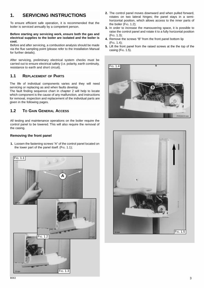
2. The control panel moves downward and when pulled forward,rotates on two lateral hinges; the panel stays in a semi-horizontal position, which allows access to the inner parts ofthe boiler (FIG. 1.2);
3. In order to increase the manouvering space, it is possible toraise the control panel and rotate it to a fully horizontal position(FIG. 1.3);
4. Remove the screws “B” from the front panel bottom lip (FIG. 1.4);
5. Lift the front panel from the raised screws at the the top of thecasing (FIG. 1.5).
FIG. 1.4
B
FIG. 1.5
3B063
1. SERVICING INSTRUCTIONS
The life of individual components varies and they will needservicing or replacing as and when faults develop.The fault finding sequence chart in chapter 2 will help to locatewhich component is the cause of any malfunction, and instructionsfor removal, inspection and replacement of the individual parts aregiven in the following pages.
1.1 REPLACEMENT OF PARTS
1.2 TO GAIN GENERAL ACCESS
All testing and maintenance operations on the boiler require thecontrol panel to be lowered. This will also require the removal ofthe casing.
Removing the front panel
1. Loosen the fastening screws “A” of the control panel located onthe lower part of the panel itself. (FIG. 1.1);
A
FIG. 1.3
FIG. 1.1
FIG. 1.2
To ensure efficient safe operation, it is recommended that theboiler is serviced annually by a competent person.
Before starting any servicing work, ensure both the gas andelectrical supplies to the boiler are isolated and the boiler iscool.Before and after servicing, a combustion analysis should be madevia the flue sampling point (please refer to the Installation Manualfor further details).
After servicing, preliminary electrical system checks must becarried out to ensure electrical safety (i.e. polarity, earth continuity,resistance to earth and short circuit).
19.eps
14.eps
13.eps
FO016A/15.eps
16.eps
4 B063
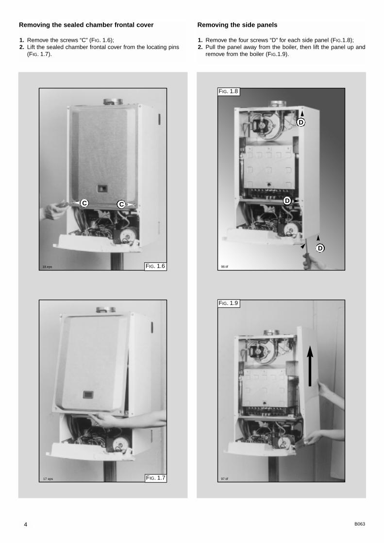
Removing the sealed chamber frontal cover
1. Remove the screws “C” (FIG. 1.6);2. Lift the sealed chamber frontal cover from the locating pins
(FIG. 1.7).
FIG. 1.6
CC
FIG. 1.7
Removing the side panels
1. Remove the four screws “D” for each side panel (FIG.1.8);2. Pull the panel away from the boiler, then lift the panel up and
remove from the boiler (FIG.1.9).
D
D
D
FIG. 1.8
FIG. 1.9
18.eps 98.tif
17 eps 97.tif
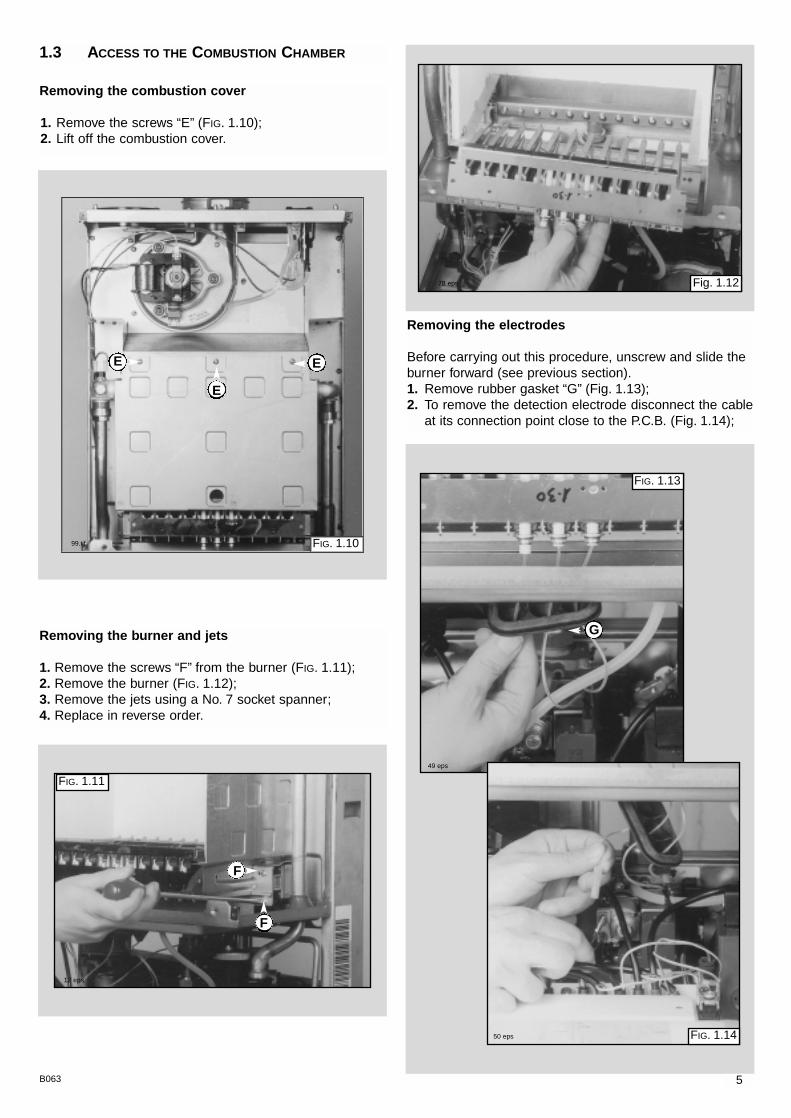
Removing the electrodes
Before carrying out this procedure, unscrew and slide theburner forward (see previous section).1. Remove rubber gasket “G” (Fig. 1.13);2. To remove the detection electrode disconnect the cable
at its connection point close to the P.C.B. (Fig. 1.14);
FIG. 1.13
G
FIG. 1.14
Removing the burner and jets
1. Remove the screws “F” from the burner (FIG. 1.11);2. Remove the burner (FIG. 1.12);3. Remove the jets using a No. 7 socket spanner;4. Replace in reverse order.
5B063
Removing the combustion cover
1. Remove the screws “E” (FIG. 1.10);2. Lift off the combustion cover.
1.3 ACCESS TO THE COMBUSTION CHAMBER
E
E
E
FIG. 1.10
FIG. 1.11
Fig. 1.12
F
F
99.tif
12 eps
78 eps
49 eps
50 eps
6 B063
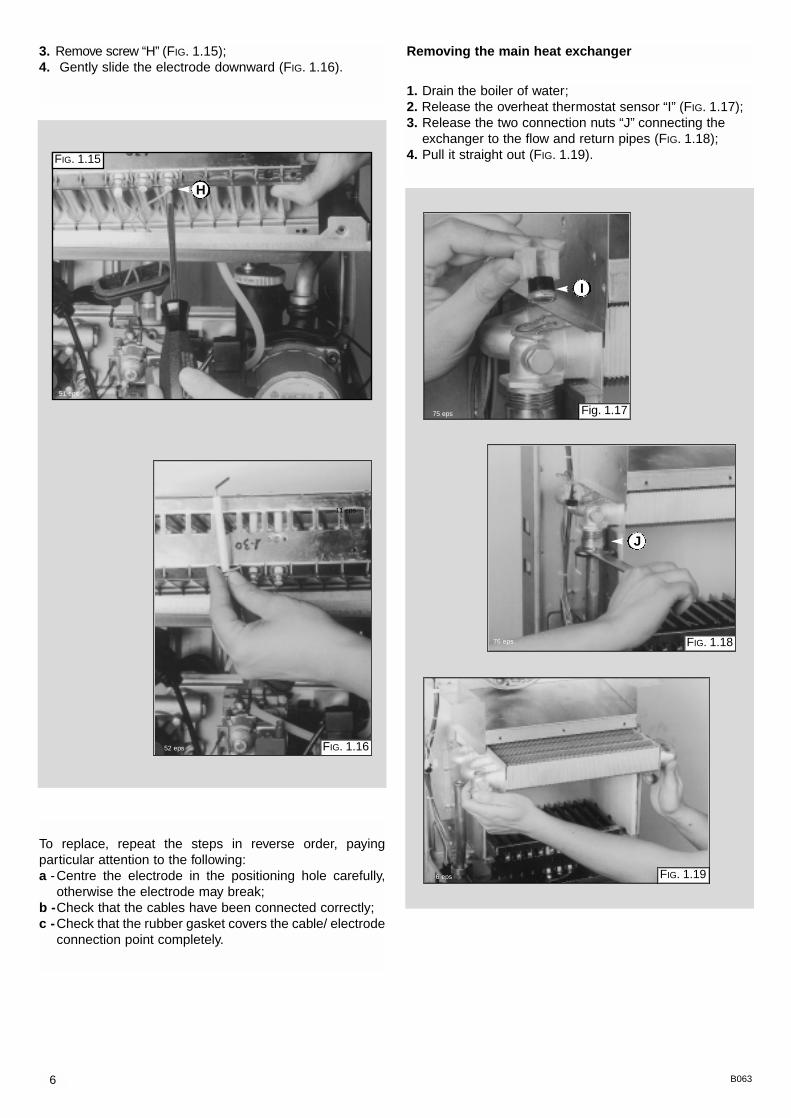
3. Remove screw “H” (FIG. 1.15);4. Gently slide the electrode downward (FIG. 1.16).
To replace, repeat the steps in reverse order, payingparticular attention to the following:a -Centre the electrode in the positioning hole carefully,
otherwise the electrode may break;b -Check that the cables have been connected correctly;c -Check that the rubber gasket covers the cable/ electrode
connection point completely.
FIG. 1.15
FIG. 1.16
H
1. Drain the boiler of water;2. Release the overheat thermostat sensor “I” (FIG. 1.17);3. Release the two connection nuts “J” connecting the
exchanger to the flow and return pipes (FIG. 1.18);4. Pull it straight out (FIG. 1.19).
Removing the main heat exchanger
FIG. 1.18
J
Fig. 1.17
I
FIG. 1.19
51 eps
11 eps
52 eps
75 eps
76 eps
6 eps

1. Disconnect electrical connections “N” and silicon pipes“O” (FIG.1.23);
2. Remove screw “P” and remove the fan collar clamp “Q”(FIG.1.24);
3. Remove screws “R” (FIG.1.25);4. Remove fan and mounting plate (FIG.1.26).
Removing the fan
1. Disconnect the electrical connections “K” and silicon pipes“L” from their connection points (FIG. 1.20);
2. Remove screws “M” on the top of the sealed chamber(FIG. 1.21);
3. Unscrew to remove switch from the plate (FIG. 1.22).
FIG. 1.21
FIG. 1.20
7B063
Removing the air pressure switch
L
K
M
M
FIG. 1.22
FIG. 1.25
R R
FIG. 1.24
PQ
FIG. 1.23
NN
O
FIG. 1.26
91.tif
90.tif 93.tif
94.tif
95.tif
96.tif

8 B063
1.4 SERVICING AND REMOVAL
OF THE GAS VALVE
Setting the gas pressures
1
2
Recommended pressure for soft-light ignition 8 mbar
NATURAL GAS (G20) BUTANE GAS (G30) PROPANE GAS (G31)
16 mbar 16 mbar
3
4
A
B
C
E
F
D
Setting the minimum and the maximum power of the boiler1. Check that the supply pressure to the gas valve is a minimum of 20 mbar
for natural gas.2. To do this, remove the screw “A”.
Fit the pipe of the pressure gauge to the pressure connection of the gasvalve “B”.When you have completed this operation, replace the screw “A” securelyinto its housing to seal off the gas.
3. To check the pressure supplied by the gas valve to the burner, remove thescrew “C”. Fit the pipe of the pressure gauge to the pressure outlet of the gas valve “D”.Disconnect the compensation pipe either from the gas valve or from the sealed chamber.
4. Set the On/Off button to position < I > and the “summer/winter” switch tothe winter position.To set the maximum power, turn on the hot water tap and allow the hotwater tap to run at a rate of about 8 litres/minute so that the main burnerlights.Adjust nut “E” on the modureg to set the gas pressure (displayed on thepressure gauge) corresponding to the maximum power (see TABLE “A” page9).
5. To set the minimum power, disconnect a supply terminal from the moduregand adjust screw “F”.Turn the screw clockwise to increase the pressure and coun-ter-clockwise to decrease the pressure (displayed on thepressure gauge) corresponding to the minimum power (see TABLE “A” page9).
6. When you have completed the above operations, turn off thehot water tap, re-connect the supply terminal to the moduregon the gas valve and replace the cap on the screw of themodureg.
Setting the maximum heating circuit power7. To set the maximum heating circuit power, place the
On/Off button to position < I > and the “summer/winter” switch to winterposition.Turn the knob of the heating thermostat clockwise to maximum.
8. Remove the inspection panel of the P.C.B. and fit a small cross-headscrewdriver in to the right hand potentiometer. Turn clockwise to increasethe pressure or counter-clockwise to reduce the pressure. Adjust thesetting to the required heating pressure value (displayed on the pressuregauge), as indicated in the diagrams shown in page 10.
9. Turn off the boiler by placing the main switch to the "Off" position.
Setting pressure for soft ignition.Disconnect the detection electrode connection from the P.C.B..Start the boiler and during the ignition sequence adjust the left handpotentiometer until the gas pressure reads the required gas pressure asper the table below.Once the gas pressure is set turn off the boiler and re-connect theconnection to the P.C.B.NB.: It may be necessary to reset the flame failure reset a number of timesduring this operation.
VG001Aa
VG001Ac
VG001Ab
VG001Ad
9B063
model 23
model 27
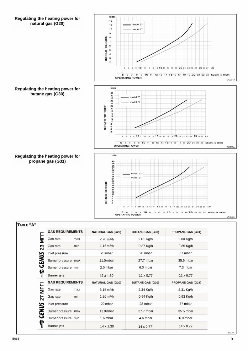
Regulating the heating power fornatural gas (G20)
model 23
model 27
Regulating the heating power forbutane gas (G30)
model 23
model 27
34363840
Regulating the heating power forpropane gas (G31)
23 M
FF
I
2.70
20
11.0
2.0
1.16
2.01 Kg/h
0.87 Kg/h
27.7 mbar
6.0 mbar
28 mbar
12 x 0.77
2.00 Kg/h
0.85 Kg/h
35.5 mbar
7.3 mbar
37 mbar
12 x 0.77
27 M
FF
I
3.15
20
11.0
1.6
1.26
2.34 Kg/h
0.94 Kg/h
27.7 mbar
4.6 mbar
28 mbar
2.31 Kg/h
0.93 Kg/h
35.5 mbar
6.0 mbar
37 mbar
14 x 1.30 14 x 0.77 14 x 0.77
TABLE “A”
CG007A
CG008A
CG009A
TB012A

10 B063
Removing the spark generator
1. Disconnect ignition leads “T” by pulling upward(FIG. 1.27);
2. Remove the screw “V” (FIG. 1.28);3. Remove the spark generator (FIG. 1.29).
10. Remove the pipe from the pressure gauge and connectscrew “C” to the pressure outlet in order to seal off thegas.
11. Carefully check the pressure outlets for gas leaks (valveinlet and outlet).
IMPORTANT!Whenever you disassemble and reassemble the gasconnections, always check for leaks using a soap and watersolution.
FIG. 1.27
FIG. 1.28
FIG. 1.29
T
V
Soft-lightAdjustment
Max HeatingAdjustment
61.eps
45.eps
43.eps
44.eps
VR015A.eps

11B063
Important! Before any component is removed, the boilermust be drained of all water.
Removing the D.H.W. (secondary) exchanger
1.Remove the screws “Y” (FIG 1.33 + FIG 1.34);2.Push the exchanger towards the rear of the boiler, and lift
upwards and remove out of the front of the boiler (FIG 1.35);
3.Before replacing the exchanger ensure that the O-ringsare in good condition and replace if necessary.
1.6 ACCESS TO THE WATER CIRCUIT
FIG. 1.30
FIG. 1.31
FIG. 1.32
FIG. 1.33
W
XX
Removing the gas valve
1. Disconnect all the cables from the solenoid andmodureg;
2. Remove the spark generator (see previous section);3. Release the top nut “W” (FIG. 1.30);4. Remove the screws “X” from the bottom of the gas valve
pipe (FIG. 1.31);5. Remove the gas valve (FIG. 1.32).
Y
FIG. 1.34
FIG. 1.35
Y
47.eps
48.eps
38.eps
22.eps
21.eps
68.eps

12 B063
Removing the safety valve1. Loosen nut “Z” (FIG. 1.36);2. Unscrew and remove the valve (FIG. 1.37).
Removing the automatic air vent1. Unscrew valve top “A1” (FIG. 1.38);2. Remove valve (Fig 1.39).
Removing the main circuit flow switch
1. Remove the cable of the main circuit flow switch “B1”(FIG. 1.40);
2. Remove the screws “C1” (FIG. 1.41);3. Remove the main circuit flow switch.
FIG. 1.36
Fig. 1.38
FIG. 1.40
Z
B1
C1
C1
FIG. 1.37
A1
Fig. 1.39
FIG. 1.41
40.eps
37.eps
39.eps
41.eps
53.eps
54.eps

13B063
Removing the pump
1. Remove the U-clip “ D1” (FIG. 1.41);2. Remove the retaining clip “E1” (FIG. 1.42);3. Remove the U-clip “ F1” (FIG. 1.43);4. Release the nut “G1” (FIG. 1.44);5. Remove the pipe “H1” (FIG. 1.45);6. Remove the screws “I1” (FIG. 1.46);7. Remove the pump (FIG. 1.47).
D1
FIG. 1.41
FIG. 1.42
FIG. 1.43
FIG. 1.44
E1
F1
FIG. 1.45
FIG. 1.46
FIG. 1.47
G1
H1
I1I1
31.eps
33.eps
34.eps
42.eps
32.eps
35.eps
25.eps

14 B063
Removing the expansion vessel
1. Loosen nuts “K1” and remove the gas pipe (FIG. 1.50);2. Loosen nut “L1” (FIG. 1.51);3. Remove back nut “M1” (FIG. 1.52);4. Remove the expansion vessel (FIG. 1.53).
Removing the pressure gauge
1. Remove the U-clip “J1” and remove the pressure gaugecoupling (FIG. 1.48);
2. Push the pressure gauge through the control panel fromthe rear (FIG. 1.49).
FIG. 1.48
FIG. 1.50
J1
FIG. 1.49
K1
L1
FIG. 1.51
FIG. 1.52
FIG. 1.53
K1
M1
34.eps
27.eps
77.eps
57.eps
58.eps
59.eps
15B063
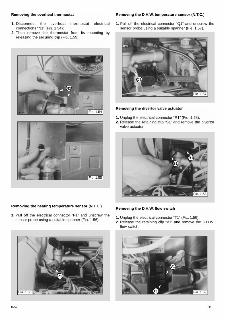
Removing the overheat thermostat
1. Disconnect the overheat thermostat electricalconnections “N1” (FIG. 1.54);
2. Then remove the thermostat from its mounting byreleasing the securing clip (FIG. 1.55).
Removing the heating temperature sensor (N.T.C.)
1. Pull off the electrical connector “P1” and unscrew thesensor probe using a suitable spanner (FIG. 1.56).
FIG. 1.54
FIG. 1.55
Removing the D.H.W. temperature sensor (N.T.C.)
1. Pull off the electrical connector “Q1” and unscrew thesensor probe using a suitable spanner (FIG. 1.57).
FIG. 1.57
Removing the divertor valve actuator
1. Unplug the electrical connector “R1” (FIG. 1.58);2. Release the retaining clip “S1” and remove the divertor
valve actuator.
FIG. 1.58
Removing the D.H.W. flow switch
1. Unplug the electrical connector “T1” (FIG. 1.59);2. Release the retaining clip “V1” and remove the D.H.W.
flow switch.
FIG. 1.59
N1
P1
Q1
S1
R1
FIG. 1.56 T1
V1
80.eps
83.eps
87.eps
60.eps
74.eps
30.eps

16 B063
Checking the fuses
1. Remove the inspection cover on the reverse of thecontrol panel (FIG. 1.60);
2. Remove the fuses (FIG. 1.61).
1.6 ACCESS TO THE CONTROL SYSTEM Removing the time clock
1. Unplug electrical connection “W1” from the clock (FIG.1.62);
2. Remove the screws “W2” (see fig. 1.63);3. Remove the clock from the panel (see fig. 1.64).
FIG. 1.60 FIG. 1.62
FIG. 1.61
FIG. 1.64
W1
72.eps
61.eps
69.eps
1190.tif
FIG. 1.631189.jpg
W2
17B063
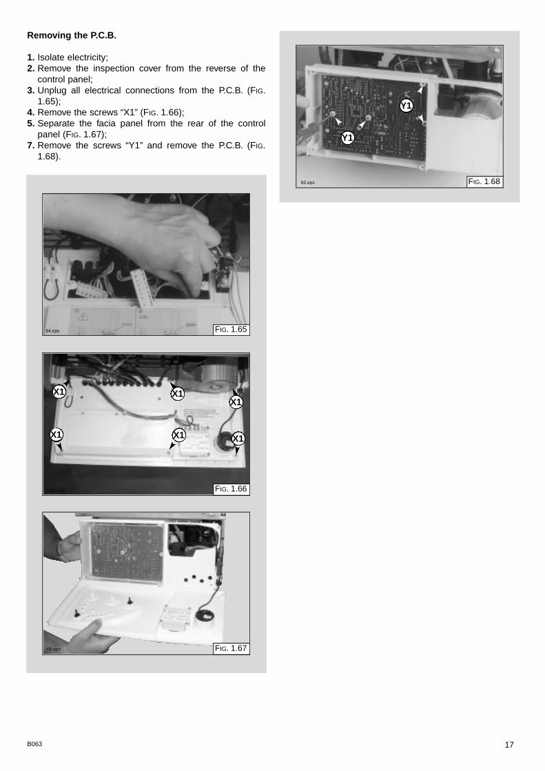
Removing the P.C.B.
1. Isolate electricity;2. Remove the inspection cover from the reverse of the
control panel;3. Unplug all electrical connections from the P.C.B. (FIG.
1.65);4. Remove the screws “X1” (FIG. 1.66);5. Separate the facia panel from the rear of the control
panel (FIG. 1.67);7. Remove the screws “Y1” and remove the P.C.B. (FIG.
1.68).
FIG. 1.66
X1
X1
X1
X1
X1
X1
FIG. 1.65
FIG. 1.67
FIG. 1.68
Y1
Y1
64.eps
1187.eps
65.eps
82.eps

18 B063
2. FAULT FINDING
PRELIMARY CHECKSMAKE SURE THAT:
ISTHE POWER
L.E.D.ON?
POSTIONOF THE
SELECTOR
NO
NO
WINTERESTAT ESUMMER
NONO
YESYES
YESYES
YESYESYESYES
YESYES
NONO
NONONONO
NONONONO
NONO
NONO
YESYES
YESYES
YESYES
1 - Check the fuses2 - Check the power supply cable, plug and outlet3 - Check/replace the power supply to the P.C.B.
TURN ON THE ON/OFFSWITCH
D.H.W. ISBEING DRAWN?
D.H.W. ISBEING DRAWN?
FOR BOILERSWITH ELECTRONIC
ANTI-FROST DEVICE:PROTECTION IS ACTIVATED
IF HEATING TEMPIS < 5°C
FOR BOILERSWITH ELECTRONIC
ANTI-FROST DEVICE:PROTECTION IS ACTIVATED
IF HEATING TEMPIS < 5°C
MUSTTIME CLOCK
AND/OR ROOMTHERMOSTAT
BE ACTIVATED?
A
ECONOMY/COMFORTSELECTOR
TEMP.C.H. < 34°C
ComfortComfort
Economy
Economy
1 - There is sufficient water in the system2 - The gas is turned on 3 - The electrical supply is turned on
1 - Check/reset system pressure2 - Check/restore gas supply3 - Check/replace short- circuited heating probe4 - Check/replace siezed pump
1 - Check/reset the system pressure2 - Check/restore gas supply3 - Check/replace short- circuited heating probe4 - Check/replace siezed pump
TEMP.C.H. < 34°C
ECONOMY/COMFORTSELECTOR
It is possible to detect and correct any defect by using the standard faultfinding diagrams described in this chapter.
2.1 FAULT FINDING GUIDE
(FLOW-CHARTS)
FC004Aa

19B063
IS THE PUMPRUNNING?
YES
NO
NO
NO
YES
YESYES
POWER TOTHE PUMP?
DOES THE"NO WATER" L.E.D.
ILLUMINATE(WITHIN 40 SECS)?
1 - Check if there is air in the system2 - Check main circuit flow switch operation3 - Check pressure on the water gauge and fill system to return to 1 bar
1 - Turn the boiler off then on (protection reset)
1 - Check that the pump is not stuck2 - Release/replace pump
1 - Check pump cable2 - Check/replace P.C.B.3 - Check main flow main switch operation when drawing D.H.W.
A
B
FC004Ab

20 B063
IS THE FANRUNNING?
BOILERSHUTDOWN?
POWERTO FAN?
NO
YES
YES
YES
NO
YES
NO
NO
NO
YES
1 - Check/replace main circuit flow switch2 - Check/replace connection cable3 - Check/replace P.C.B.
1 - Check/replace air pressure switch2 - Check if reset button is jammed3 - Check/replace flame detection electrodes
1 - Check/replace connection cable2 - Check/replace P.C.B.3 - Check/replace air pressure switch
1 - Replace fan
1 - Reset the boiler
PUMP PROTECTIONACTIVATED?
INTERNALP.C.B. PROTECTION
ACTIVATED?
B
C
FC004Ac

21B063
IS THE BURNERALIGHT?
YES
NO
YES
YES
YES
NO
NO
NO
NO
YES
1 - Check/replace ignition electrode2 - Check ignition cable3 - Check spark generator4 - Check ignition electrode cable5 - Check/replace P.C.B.
1 - Check if flame strikes detection electrode2 - Check soft-light gas pressure3 - Check/replace detection electrode4 - Check/replace P.C.B.
1 - Check power supply of gas valve2 - Check/replace P.C.B.3 - Check efficiency of gas valve4 - Replace gas valve
Shutdown L.E.D. offfan restarts
IS THEAIR PRESSURE SWITCH
ACTIVATED?
CHECK∆P ON TESTPRESSURE
INTAKE
IS FLUEDISCHARGENORMAL?
HAS THEBOILER SAFETY
SHUTDOWN BEENACTIVATED?
HAS THEBOILER SAFETY
SHUTDOWN BEENACTIVATED?
1 - Check exhaust discharge2 - Check venturi & pipes3 - Check fan efficiency
1 - Check A.P. switch cable2 - Check/replace A.P. switch3 - Check/replace P.C.B.
C
D
P 1.2 mbar
P 1.2 mbar
∆
∆
∅
≤
FC004Ad

22 B063
ISTHERE STILLA PROBLEM?
NORMALOPERATION
NO
YES
FAULTS POSSIBILE CAUSES1
2
3
4
5
6
7
8
9
D
Drawing D.H.W:When you turn on a tapburner switches off
Drawing D.H.W:radiators heat up in summer mode
Drawing D.H.W:insufficient hot watertemperature
Drawing D.H.W:noisy operation
Decrease/increaseheating circuit pressure
Repeated shutdowns
Repeated intervention of safety thermostat
When cold water tap turned off, the boilerignites
Insufficient radiator temperature
- air in secondary heat exchanger- faulty main circuit flow switch- faulty D.H.W. flow switch
- faulty 3-way valve
- check C.H./D.H.W. temperature probes- check gas pressures- check water flow rate- check secondary heat exchanger
- primary heat exchanger faulty or lime-scale deposits- low heating system water pressure- check gas pressures- check C.H./D.H.W. temperature probes
- check for leaks on the heating circuit- faulty filling-loop- faulty secondary heat exchanger- expansion vessel faulty
- faulty detection electrodes- check gas settings- check flame detection electric circuit
- C.H./D.H.W. temperature probes open circuit- overheat thermostat not calibrated correctly- air in primary water circuit
- drop in pressure in the water mains, with consequent water hammer
- check C.H. temperature probe- check by-pass- check gas pressures
FC004Ae
23B063
3. ELECTRICAL
DIAGRAMS
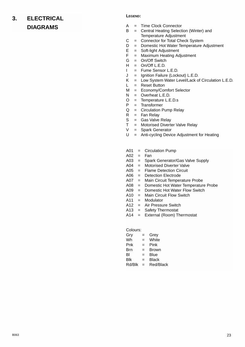
LEGEND:
A = Time Clock ConnectorB = Central Heating Selection (Winter) and
Temperature AdjustmentC = Connector for Total Check SystemD = Domestic Hot Water Temperature AdjustmentE = Soft-light AdjustmentF = Maximum Heating AdjustmentG = On/Off SwitchH = On/Off L.E.D.I = Fume Sensor L.E.D.J = Ignition Failure (Lockout) L.E.D.K = Low System Water Level/Lack of Circulation L.E.D.L = Reset ButtonM = Economy/Comfort SelectorN = Overheat L.E.D.O = Temperature L.E.D.sP = TransformerQ = Circulation Pump RelayR = Fan RelayS = Gas Valve RelayT = Motorised Diverter Valve RelayV = Spark GeneratorU = Anti-cycling Device Adjustment for Heating
A01 = Circulation PumpA02 = FanA03 = Spark Generator/Gas Valve SupplyA04 = Motorised Diverter ValveA05 = Flame Detection CircuitA06 = Detection ElectrodeA07 = Main Circuit Temperature ProbeA08 = Domestic Hot Water Temperature ProbeA09 = Domestic Hot Water Flow SwitchA10 = Main Circuit Flow SwitchA11 = ModulatorA12 = Air Pressure SwitchA13 = Safety ThermostatA14 = External (Room) Thermostat
Colours:Gry = Grey Wh = WhitePnk = PinkBrn = BrownBl = BlueBlk = BlackRd/Blk = Red/Black

24 B063
microGENUS 23/27 MFFI
J K
Blk
Blk
Gry
Gry
Pnk
Pnk
Pnk
Gry
Gry
Wh
Wh
Wh
Wh
Wh
Wh
Wh
Rd/B
lk
Rd/B
lk
Rd/B
lk
Blk
Blk
Blk
Brn
Brn
Brn
Brn
Blk
Blk
SE017A
UJK
ML
R
SQT
ON
SF014A

25B063
1814 18 22
301 302 303
2826 2724 25 34
55 53
7
11
12
13
14
77
17
16
15
8
9
10
6
5
4
3
2
304
49
48
47
46
45
43
54
1
5
910
9 95762 596061 56
9
63
1213
77
76
80
2320 2119 3635 38
42
41
34
4092
9091
42
32 333029 31
89
25
105
96
95
101
98
10099
75
878382
84 86
14
85
69
70
7172
102
71
74
107108 106
104
64
103
14
56
58
956 56
81
73
37 39
93
97
44
887879
6665
6867
5152
50
94
334331
332 333
code 998613
311
code 998940 codes 998836
354
353
352351
371
372373
374
375
code 998099
321
code 997089
MODELS CHARACTERISTICS SERIAL NO:VALIDITY
REF.
MICROGENUS 23 MFFI METHANE 2320005600001 A
MICROGENUS 23 MFFI LPG 2320005600001 B
MICROGENUS 27 MFFI METHANE 2320005600001 C
MICROGENUS 27 MFFI LPG 2320005600001 D
999091
4. SHORT SPARE
PARTS LIST
microGENUS 23/27 MFFI

26 B063
microGENUS 23/27 MFFI
998616573521998077573520997147997077569236998613571547998099998940998424574279998645997089998836999091999599998947999245573989571651999397998894997206998620998893998618998669998887998939571646573295573825573172998623998622998624998941997029998490998718998975998974998644998643998738998961999207571547 571772571771571770998172998716998717
Keyno.
G.C. partno.
ARISTONPart No.Description
25
1214161718192021242526272833 AB33 CD384143
52AB52CD66AB66CD
7274AB74CD
75C75D
76AB76CD
75A75B
77799899100
311321331332333334351352353354 AB354 CD371372373374375381382
379816E61 468164 282E61 475164 225E25 427E61 429164 338E61 478E24 077E61 479E61 482E61 483E25 529E61 848E61 485E61 490E61 881
E61 519E61 520E61 530E03 818
E61 967E25 425
E61 546E61 547E61 549E61 972E61 974E26 767E26 657E26 658E26 378E61 565E61 567E61 569
E25 582E61 647E61 648E61 649E61 650E61 652E61 654E61 656E61 660E62 030E24 077E24 077E24 076E24 075E61 663E61 665E61 667
Expansion vesselGasket 3/8"O-ringGasket 3/4"Motor (3- Way valve)Fixing clip (motor)Temperature probe (C.H.W.)Flow groupDiaphragm (main flow switch)Main circuit flow switchReturn groupO-ringGasketSpark generatorGas valve (SIT 845 SIGMA)PumpPumpTime clockP.C.B. (CMP1-FFI)Pressure gaugeAir pressure switchAir pressure switchFanFanThermostat (overheat)Main exchangerMain exchangerBurner 12 ramp (natural gas)Burner 12 ramp (LPG)Burner 14 ramp (natural gas)Burner 14 ramp (LPG)Secondary exchanger (p-type 23kW)Secondary exchanger (p-type 27kW)O-ring (secondary exchanger)Safety valve (1/2" 3 bar)Electrode (Ignition R.H.)Electrode (Ignition L.H.)Detection electrodeD.H.W. actuator kitOperator coils (SIT SIGMA)Central heating by-pass kitHeating spring kit3-way spring kitActuator bushGasket (auto air vent)Auto air ventGasket (pump head)Pump head (Gold 15/5)Pump headDiaphragm (main flow switch)Magnet (main flow switch)Spring (main flow switch)Main flow switch top capMain flow switch reed systemBurner jet 1.25 full kit (Natural gas)Burner jet 0.72 full kit (LPG)
1
1111
1111111111111
11
1
1111
111111111111


23 9
9 84
147
0 31
2 -
Sta
mpa
:Bie
ffe
Rec
anat
i
Manufacturer: Merloni TermoSanitari SpA - Italy
Commercial subsidiary: MTS (GB) LIMITEDMTS BuildingHughenden AvenueHigh WycombeBucks HP13 5FTTelephone: (01494) 755600 Fax: (01494) 459775internet: http://www.mtsgb.ltd.ukE-mail: [email protected] Service Hot Line: (01494) 539579

SPARE PARTS EXPLODED VIEWGAS WALL BOILERSModelsMICROGENUS 23 MFFIMICROGENUS 27 MFFIEdition 1 of 1 December 1999

1814 18 22
301 302 303
2826 2724 25 34
55 53
7
11
12
13
14
75
17
16
15
8
9
10
6
5
4
3
2
304
49
48
47
46
45
43
52
54
1
5
910
9 95762 596061 56
9
63
1213
75
74
77
79
2320 2119 3635 38
42
41
34
4090
8889
42
32 333029 31
87
25
102
93
92
98
95
9796
73
858180
82 84
14
83
67
68
6970
99
69
72
104105 103
101
64
6566 100
14
56
58
956 56
78
71
37 39
91
51
50
94
44
8676
334331
332 333
code 998613
311
code 998940 code 998836
354
353
352351
371
372
373374
375
code 998099
321
code 997089
MODELS CHARACTERISTICS SERIAL NO:VALIDITY
REF.
MICROGENUS 23 MFFI METHANE 9932200020 A
MICROGENUS 23 MFFI LPG 9932300018 B
MICROGENUS 27 MFFI METHANE 9932500011 C
MICROGENUS 27 MFFI LPG 9932400027 D

PART. CODE DESCRIPTION REF. NOTE 1 ------ Frame 11 2 998616 Expansion vessel 3 998776 Bush 4 998581 3/8" lock nut 5 573521 3/8" gasket 6 998584 Pipe (expansion vessel) 7 998580 Cable holder 8 ------ Hydraulic group support 11 9 570717 Spring (fastening) 10 998569 Pivot 11 998589 By-pass pipe 12 998077 O-ring gasket 13 998064 Spring (by-pass pipe) 14 573520 Gasket 3/4" 15 998815 Pipe (flow) 16 997147 Motor (3-Way valve) 17 997077 Fixing clip (motor) 18 569236 Temperature probe (C.H.W.) 19 998613 Flow group 20 571547 Diaphragm (main flow switch) 21 998099 Main circuit flow switch 22 998632 Cable (temperature probes) 23 999075 D.H.W. flow switch 24 998940 Return group 25 998424 O-ring 26 574279 Gasket 27 998645 Spark generator 28 997089 Gas valve (SIT 845 SIGMA) 29 998606 Pump bracket 30 998568 Pump plug 31 997182 Gasket 32 998452 Lock washer 33 998836 Pump 34 998570 L.E.D. 35 998575 Spindle (temperature knob) 36 998603 Control knob 37 998572 Spindle (on/off knob) 38 997207 Time clock 39 998827 Front cover 40 998824 Control panel 41 998642 Printed circuit board (CMP1-FFI) 42 569711 Nylon bush (10mm) 43 998625 Pressure gauge 44 ------ Control panel 11 45 ------ Cable holder cover 11 46 571548 Clip (Main Flow Switch) 47 998861 Cable (power supply) 48 998859 High voltage wiring 49 998863 Low voltage wiring 50 573327 "Y" piece (air pressure) 51 571575 Silicone pipe (positive signal) 52 571651 Air pressure switch CD 52 573989 Air pressure switch AB 53 997203 Support plate (Air pressure switch) 54 573329 Pressure intake cover 55 569662 Silicone pipe 56 998516 10x6 adhesive gasket 57 ------ Sealed chamber 11 58 998565 Cover (flue test point) 59 998636 Gasket (flue test point) 60 998602 Flue (exhaust manifold/header) 61 998637 Flange gasket 62 998595 Plug (air intake) 63 998648 Sealed chamber wiring 64 998566 Fixing clamp (fan)

PART. CODE DESCRIPTION REF. NOTE 65 998601 Fixing plate (fan) AB 66 998621 Fan AB 66 998894 Fan CD 67 998640 Insulation panel (Rear) AB 67 998896 Insulation panel (Rear) CD 68 998600 Panel (combustion chamber - L.H. side) 69 998639 Insulation panel (Side) 70 997206 Thermostat (overheat) 71 998583 Fixing spring (Limit thermostat) 72 998620 Main exchanger AB 72 998893 Main exchanger CD 73 998618 Burner 12 ramp (natural gas) A 73 998669 Burner 12 ramp (LPG) B 73 998887 Burner 14 ramp (natural gas) C 73 998939 Burner 14 ramp (LPG) D 74 571646 Secondary exchanger (p-type 23kW) AB 74 573295 Secondary exchanger (p-type 27kW) CD 75 573825 O-Ring (secondary exchanger) 76 998629 Cable (3-way valve motor) 77 998567 Safety valve exhaust pipe ring nut 78 573176 Pipe (safety valve outlet) 79 573172 Safety valve (1/2" 3 bar) 80 573576 Compensation tube 81 573325 Rivet 82 569443 Silicone seal 83 572138 Burner jet washer 84 998714 Burner jet (NG 1.30) AC 84 998715 Burner jet (LPG 0.77) BD 85 998729 Pipe (gas valve) 86 998732 Pipe (C.H. return) 87 997153 U-clip 88 998604 Reset button 89 998571 Reset button (insert) 90 998605 Selector button (comfort) 91 998579 Spindle (comfort) 92 998862 Cable (detection electrode) 93 569720 Blind grommet 94 998517 Gasket 95 998623 Electrode (Ignition R.H.) 96 998622 Electrode (Ignition L.H.) 97 998624 Detection electrode 98 998147 Ignition electrode cable rubber 99 998599 Panel (combustion chamber - R.H.side)100 998598 Panel (combustion chamber front) AB100 998924 Panel (combustion chamber front) CD101 998719 Flue hood AB101 998925 Flue hood CD102 998638 Insulation panel (Front) AB102 998895 Insulation panel (Front) CD103 998076 View window glass gasket104 998075 View window glass105 998610 Panel (front - sealed chamber)
301 998477 Case panel (L.H. side)302 998596 Insert case303 998476 Case panel (R.H. side)304 998607 Panel (front case)
311 998941 D.H.W. actuador kit
321 997029 Operator coils (Sit Sigma)
331 998490 Central heating by-pass kit332 998718 3-Way spring kit (C.H.)333 571447 3-Way spring kit
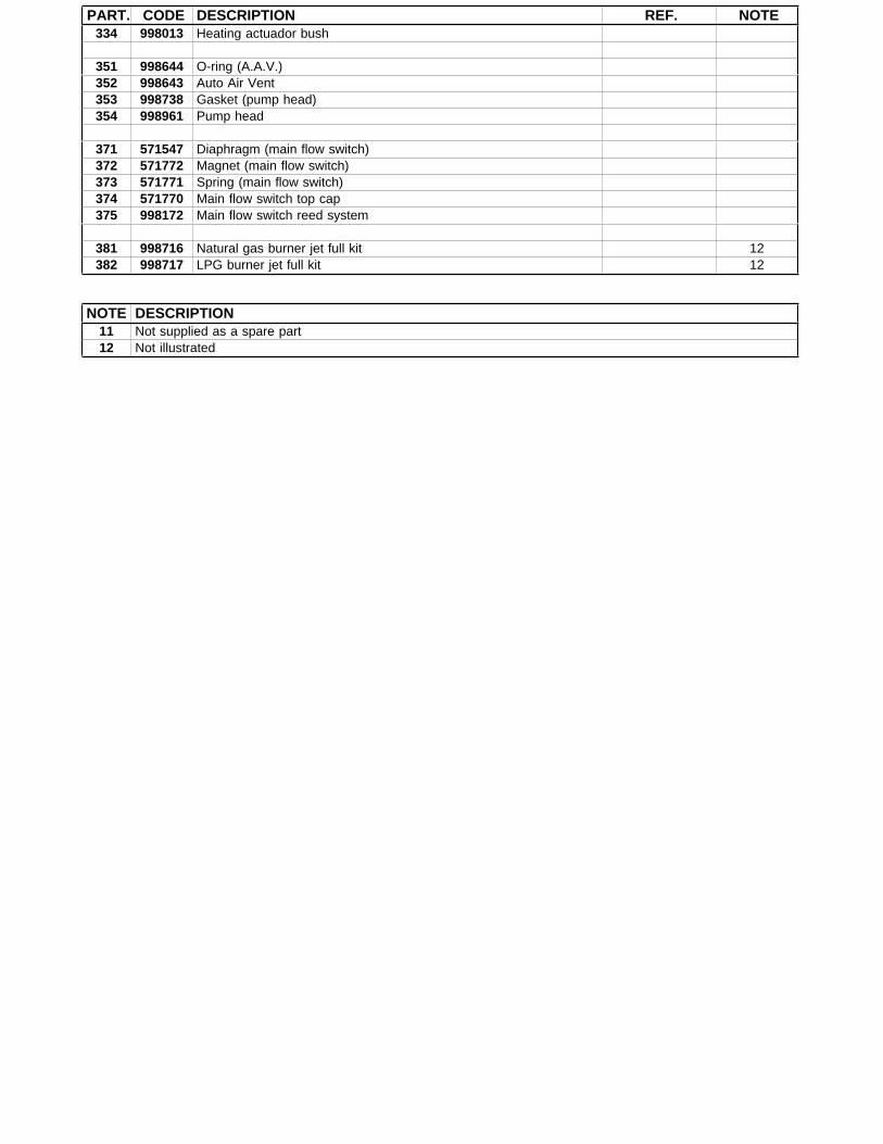
PART. CODE DESCRIPTION REF. NOTE334 998013 Heating actuador bush
351 998644 O-ring (A.A.V.)352 998643 Auto Air Vent353 998738 Gasket (pump head)354 998961 Pump head
371 571547 Diaphragm (main flow switch)372 571772 Magnet (main flow switch)373 571771 Spring (main flow switch)374 571770 Main flow switch top cap375 998172 Main flow switch reed system
381 998716 Natural gas burner jet full kit 12382 998717 LPG burner jet full kit 12
NOTE DESCRIPTION11 Not supplied as a spare part12 Not illustrated

SPARE PARTS EXPLODED VIEWGAS WALL BOILERSModelsMICROGENUS 23 MFFIMICROGENUS 27 MFFIEdition 1 of 1 December 1999
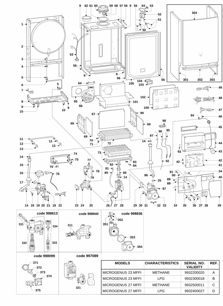
1814 18 22
301 302 303
2826 2724 25 34
55 53
7
11
12
13
14
75
17
16
15
8
9
10
6
5
4
3
2
304
49
48
47
46
45
43
52
54
1
5
910
9 95762 596061 56
9
63
1213
75
74
77
79
2320 2119 3635 38
42
41
34
4090
8889
42
32 333029 31
87
25
102
93
92
98
95
9796
73
858180
82 84
14
83
67
68
6970
99
69
72
104105 103
101
64
6566 100
14
56
58
956 56
78
71
37 39
91
51
50
94
44
8676
334331
332 333
code 998613
311
code 998940 code 998836
354
353
352351
371
372
373374
375
code 998099
321
code 997089
MODELS CHARACTERISTICS SERIAL NO:VALIDITY
REF.
MICROGENUS 23 MFFI METHANE 9932200020 A
MICROGENUS 23 MFFI LPG 9932300018 B
MICROGENUS 27 MFFI METHANE 9932500011 C
MICROGENUS 27 MFFI LPG 9932400027 D

PART. CODE DESCRIPTION REF. NOTE 1 ------ Frame 11 2 998616 Expansion vessel 3 998776 Bush 4 998581 3/8" lock nut 5 573521 3/8" gasket 6 998584 Pipe (expansion vessel) 7 998580 Cable holder 8 ------ Hydraulic group support 11 9 570717 Spring (fastening) 10 998569 Pivot 11 998589 By-pass pipe 12 998077 O-ring gasket 13 998064 Spring (by-pass pipe) 14 573520 Gasket 3/4" 15 998815 Pipe (flow) 16 997147 Motor (3-Way valve) 17 997077 Fixing clip (motor) 18 569236 Temperature probe (C.H.W.) 19 998613 Flow group 20 571547 Diaphragm (main flow switch) 21 998099 Main circuit flow switch 22 998632 Cable (temperature probes) 23 999075 D.H.W. flow switch 24 998940 Return group 25 998424 O-ring 26 574279 Gasket 27 998645 Spark generator 28 997089 Gas valve (SIT 845 SIGMA) 29 998606 Pump bracket 30 998568 Pump plug 31 997182 Gasket 32 998452 Lock washer 33 998836 Pump 34 998570 L.E.D. 35 998575 Spindle (temperature knob) 36 998603 Control knob 37 998572 Spindle (on/off knob) 38 997207 Time clock 39 998827 Front cover 40 998824 Control panel 41 998642 Printed circuit board (CMP1-FFI) 42 569711 Nylon bush (10mm) 43 998625 Pressure gauge 44 ------ Control panel 11 45 ------ Cable holder cover 11 46 571548 Clip (Main Flow Switch) 47 998861 Cable (power supply) 48 998859 High voltage wiring 49 998863 Low voltage wiring 50 573327 "Y" piece (air pressure) 51 571575 Silicone pipe (positive signal) 52 571651 Air pressure switch CD 52 573989 Air pressure switch AB 53 997203 Support plate (Air pressure switch) 54 573329 Pressure intake cover 55 569662 Silicone pipe 56 998516 10x6 adhesive gasket 57 ------ Sealed chamber 11 58 998565 Cover (flue test point) 59 998636 Gasket (flue test point) 60 998602 Flue (exhaust manifold/header) 61 998637 Flange gasket 62 998595 Plug (air intake) 63 998648 Sealed chamber wiring 64 998566 Fixing clamp (fan)
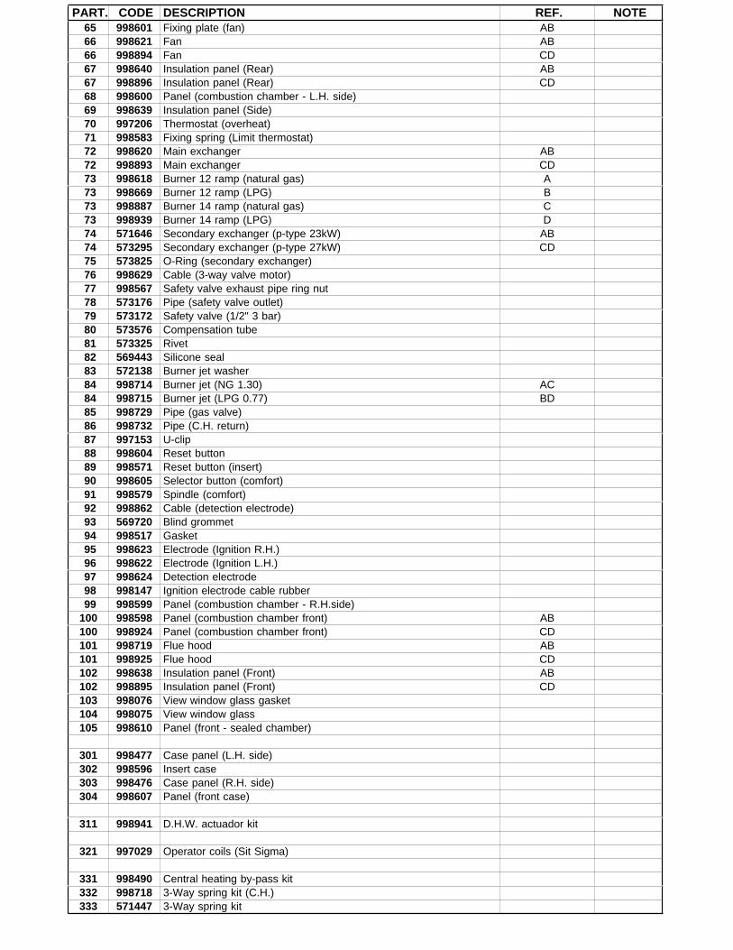
PART. CODE DESCRIPTION REF. NOTE 65 998601 Fixing plate (fan) AB 66 998621 Fan AB 66 998894 Fan CD 67 998640 Insulation panel (Rear) AB 67 998896 Insulation panel (Rear) CD 68 998600 Panel (combustion chamber - L.H. side) 69 998639 Insulation panel (Side) 70 997206 Thermostat (overheat) 71 998583 Fixing spring (Limit thermostat) 72 998620 Main exchanger AB 72 998893 Main exchanger CD 73 998618 Burner 12 ramp (natural gas) A 73 998669 Burner 12 ramp (LPG) B 73 998887 Burner 14 ramp (natural gas) C 73 998939 Burner 14 ramp (LPG) D 74 571646 Secondary exchanger (p-type 23kW) AB 74 573295 Secondary exchanger (p-type 27kW) CD 75 573825 O-Ring (secondary exchanger) 76 998629 Cable (3-way valve motor) 77 998567 Safety valve exhaust pipe ring nut 78 573176 Pipe (safety valve outlet) 79 573172 Safety valve (1/2" 3 bar) 80 573576 Compensation tube 81 573325 Rivet 82 569443 Silicone seal 83 572138 Burner jet washer 84 998714 Burner jet (NG 1.30) AC 84 998715 Burner jet (LPG 0.77) BD 85 998729 Pipe (gas valve) 86 998732 Pipe (C.H. return) 87 997153 U-clip 88 998604 Reset button 89 998571 Reset button (insert) 90 998605 Selector button (comfort) 91 998579 Spindle (comfort) 92 998862 Cable (detection electrode) 93 569720 Blind grommet 94 998517 Gasket 95 998623 Electrode (Ignition R.H.) 96 998622 Electrode (Ignition L.H.) 97 998624 Detection electrode 98 998147 Ignition electrode cable rubber 99 998599 Panel (combustion chamber - R.H.side)100 998598 Panel (combustion chamber front) AB100 998924 Panel (combustion chamber front) CD101 998719 Flue hood AB101 998925 Flue hood CD102 998638 Insulation panel (Front) AB102 998895 Insulation panel (Front) CD103 998076 View window glass gasket104 998075 View window glass105 998610 Panel (front - sealed chamber)
301 998477 Case panel (L.H. side)302 998596 Insert case303 998476 Case panel (R.H. side)304 998607 Panel (front case)
311 998941 D.H.W. actuador kit
321 997029 Operator coils (Sit Sigma)
331 998490 Central heating by-pass kit332 998718 3-Way spring kit (C.H.)333 571447 3-Way spring kit

PART. CODE DESCRIPTION REF. NOTE334 998013 Heating actuador bush
351 998644 O-ring (A.A.V.)352 998643 Auto Air Vent353 998738 Gasket (pump head)354 998961 Pump head
371 571547 Diaphragm (main flow switch)372 571772 Magnet (main flow switch)373 571771 Spring (main flow switch)374 571770 Main flow switch top cap375 998172 Main flow switch reed system
381 998716 Natural gas burner jet full kit 12382 998717 LPG burner jet full kit 12
NOTE DESCRIPTION11 Not supplied as a spare part12 Not illustrated