installation instructions for hydraulic lift upgrade...
TRANSCRIPT

Installation Instructions for Hydraulic Lift Upgrade Kitfor the 5-Section Nutri-Pro 1540AA, 1540LL, 40A, and 40L
Before Getting Started
Before you begin installation of your Hydraulic LiftUpgrade, read these instructions carefully and check thatall parts and tools in kit are accounted for. All hand andspecialty tools for installation are provided at owner’sexpense. Please retain these installation instructions forfuture reference and parts ordering information.
These installation instructions contain information forassembling the Hydraulic Lift Upgrade to the mainmachine. Please read all instructions in your Nutri-Pro’soperator manual thoroughly before proceeding. Youroperator manual includes information on operation,adjustment, troubleshooting, and maintenance for thisattachment (some manual sections do not apply to allaccessories).Instructions contain information for all makes and modelsof the applicable machines.
General InformationThe Hydraulic Lift Upgrade kit adds sensors thatmeasure machine lift and fold angle and enables themachine wings to lift while turning.
Tools RequiredThe following tools are required for installation:
• General hand tools.
Refer to page 13 for torque values chart.
Further AssistanceIf for any reason you do not understand any part of thismanual or are otherwise dissatisfied, please contact:
Great Plains Service Department1525 E. North St.
P.O. Box 5060Salina, KS 67402-5060
Or go to www.greatplainsag.com and follow the contactinformation at the bottom of your screen for our servicedepartment.
Intended UsageThis hydraulic update is designed to prevent the wings fromlowering when making turns in the field. With the updateinstalled, wings rise when machine lifted during a turn.Please note that this update is only intended for 5-section machines that already have the front castergauge wheel update installed.
Recommended ManualsAll manuals related to this kit are available free of chargeby visiting www.greatplainsag.com. Have machine modeland serial numbers available.
Refer to page 8 for a detailed list of parts included inthese kits. Use these lists to inventory parts received.
Nutri-Pro Parts Manual1540AA/1540LL 417-480P40A/40L 407-313P
Hydraulic Lift Upgrade Reference #Nutri-Pro Applicator 1540 427-082A
Installation Guide QRC
The QR Code (Quick Response) to theleft will take you to a web installationguide. Use your smart phone or tabletto scan the QR Code with anappropriate App to begin viewing.
Nutri-Pro QRC
The QR Code (Quick Response) to theleft will take you to the Yield-Pro familyof manuals. Use your smart phone ortablet to scan the QR Code with anappropriate App to begin viewing.
© Copyright 2019 Printed 4/30/19 427-083M

Nutri-Pro Hydraulic Lift Update
Installation InstructionsPreparation
Before you begin installation of your Hydraulic LiftUpgrade kit, first hook the planter to a tractor andmove the lock handles to “Field,” unfold the machinewings, and lower the machine fully to the ground.Place the remote lever in float position to relieve anyresidual hydraulic pressure. Clean the area aroundthe pressure reducing valves by washing or usingcompressed air.For S/N B1162U and under
If you have an earlier Nutri-Pro system model, you mayneed to install an electronic down pressure valve for thehydraulic lift to function correctly. If this is the case, you willneed to acquire kit number 417-774S before installing.
Getting StartedRemove components for Hydraulic Lift Upgrade kitand check that all components are accounted for.Refer to the component list starting on page 14.Make sure to refer to the correct component lists foryour product.Make sure any required tools are on hand. See“Tools Required” on page 1 for a general list ofrecommended tools for installation.Download or order an updated Operator Manual andfamiliarize yourself with use before getting started.
1 Hydraulic Valves
Hydraulic Fluid Pressure HazardFully relieve pressure before disconnecting hydrauliclines. Escaping fluid under pressure can have sufficientforce to penetrate skin and cause serious injury. Usepaper or cardboard - not body parts - to check forhydraulic fluid leaks. Wear protective gloves and safetyglasses or goggles when working with hydraulic systems.If an accident occurs, seek immediate medical assistancefrom a physician familiar with this type of injury.
Before you begin working on the hydraulics of yourmachine, relieve pressure on hydraulic lines byunfolding wings and fully lowering the machine. Sethydraulic circuit to “float” once finished.
Use the following hydraulic diagrams to help you withthe proper routing and changes to hydraulic system.
Hoses marked with a number ‘1’ are replaced by hoses marked with ‘2’. Non-numbered hoses are reused.
GH
B
AE1
B
A
C
D
C
E1
F1
Figure 1Hydraulic Layout without Kit Installed
G
F2
H
B
AE2E2
F2
B
A
C
D
C
Figure 2Hydraulic Layout with Kit Installed
2 Great Plains | 427-083M

Installation Instructions
1a. Removing Fitting on Hydraulic CylinderLocate the center-left hydraulic cylinder.
Remove the hydraulic hose fitting from the cylinderbase and detach all hydraulic hoses from fitting.Replace removed fitting with 3/4” tee fitting (part no.811-077c).
Reattach hydraulic hose connected to far left-sidehydraulic cylinder (B) and hydraulic hose connectedto center valve block (G) to newly installed tee.
Remove hydraulic hose (F1) from machine entirelyas it will be replaced later by two new hoses (F2).
F2F2
F2F2
A
B
C
F2F2
D
E2E2
E2E2
E2E2
F2F2
GH
E2E2
BA
C
Figure 3Hydraulic Layout with Kit Installed
F1
BG
4/30/19 3

Nutri-Pro Hydraulic Lift Update
1b. Removing Tee Fitting at Center-RearAt the center-rear area of the machine, locate tee.
Disconnect tee from adjoining left - and right-hand(E1) side hydraulic hoses. Remove hoses (E1) aswell. Leave the hydraulic hose routed to the front ofthe machine attached to 3/4” tee.
1c. Installing Solenoid Valve MountInstall the valve mount (14) to the center-rear area ofthe machine. Secure the mount with 1/2 inch u-bolts(33), lock washers (27), and nuts (23).
1d. Installing Solenoid Valves to Hydraulic PlumbingAttach solenoid valves onto existing and newly added 3/4”tee fittings, and install tees to solenoid valves with 3/4”MORB fittings. Attach hydraulic hoses to thecorresponding port on the solenoid valves. Lower portsuse 34” hoses (F2) and route to center-rear hydrauliccylinders’ base. Upper ports use 48” hoses (E2) and routeto center-rear hydraulic cylinders’ rod end. Route twohydraulic hoses on tees (G and H) to the valve block.Upper hose (G) connects to return port on down pressurevalve, and lower hose (H) connects to the tank port.
1e. Installing Solenoid Valves to Valve MountInstall each solenoid valve to the valve mount with 5/16bolts (19), flat washers (29), lock washers (25), andnuts (21).
E1
HE1
1423
33
27
E2E2
E2E2
F2F2
F2F2H
G
SV10-40A
SV10-40A
19
29
29
21 25
4 Great Plains | 427-083M

Installation Instructions
1f. Installing Solenoid Valves to Hydraulic CylindersOn the left- and right-hand side center hydrauliccylinders, locate the remaining hydraulic hose fittings.
Remove fittings from right-hand side cylinder anddetach left-to-right running hydraulic hoses. Keepremaining hydraulic hose attached to each fitting.
2 Down Pressure ValveFor S/N B1162U and under
If you have an earlier Nutri-Pro system model, you mayneed to install an electronic down pressure valve for thehydraulic lift to function correctly. If this is the case, you willneed to acquire kit number 417-774S before proceeding.
If your machine already has a down pressure valveinstalled, proceed to step 5.
2a. Removing Existing Hardware
Locate the existing manually controlled hydraulicvalve on the front of the machine.
Relieve pressure from hydraulic lines, thendisconnect hydraulic hoses from valve. Detachassembly from the frame by removing U-bolt andadjoining hardware.
2b. Installing Down Pressure Valve
Attach down pressure valve assembly to the centerframe using U-bolt.
C
AE2E2
SV10-22
SV10-28
4/30/19 5
Nutri-Pro Hydraulic Lift Update
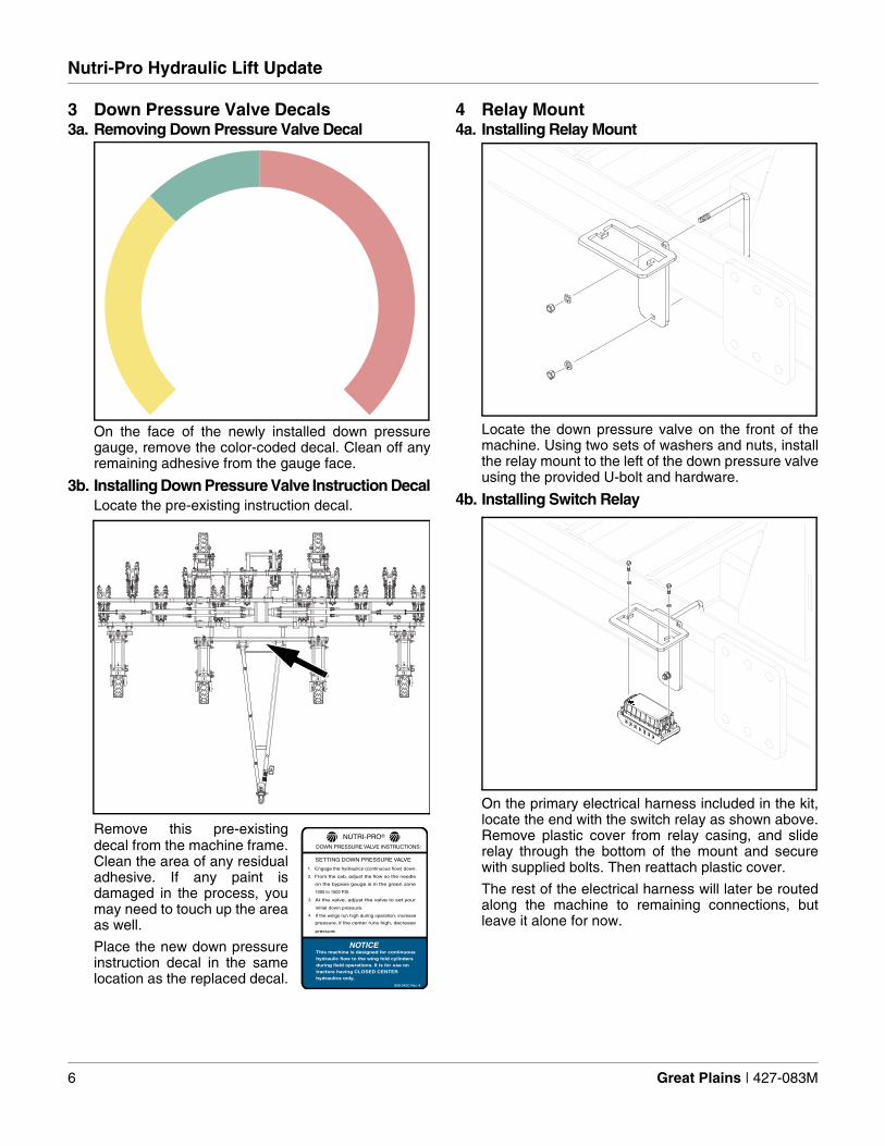
3 Down Pressure Valve Decals3a. Removing Down Pressure Valve Decal
On the face of the newly installed down pressuregauge, remove the color-coded decal. Clean off anyremaining adhesive from the gauge face.
3b. Installing Down Pressure Valve Instruction DecalLocate the pre-existing instruction decal.
Remove this pre-existingdecal from the machine frame.Clean the area of any residualadhesive. If any paint isdamaged in the process, youmay need to touch up the areaas well.
Place the new down pressureinstruction decal in the samelocation as the replaced decal.
4 Relay Mount4a. Installing Relay Mount
Locate the down pressure valve on the front of themachine. Using two sets of washers and nuts, installthe relay mount to the left of the down pressure valveusing the provided U-bolt and hardware.
4b. Installing Switch Relay
On the primary electrical harness included in the kit,locate the end with the switch relay as shown above.Remove plastic cover from relay casing, and sliderelay through the bottom of the mount and securewith supplied bolts. Then reattach plastic cover.
The rest of the electrical harness will later be routedalong the machine to remaining connections, butleave it alone for now.
858-042C Rev. A
NOTICEThis machine is designed for continuous
hydraulic flow to the wing fold cylinders
during field operations. It is for use on
tractors having CLOSED CENTER
hydraulics only.
Engage the hydraulics (continuous flow) down.1.
2. From the cab, adjust the flow so the needle
on the bypass gauge is in the green zone
1000 to 1500 PSI.
3. At the valve, adjust the valve to set your
initial down pressure.
If the wings run high during operation, increase
pressure. if the center runs high, decrease
pressure.
4.
SETTING DOWN PRESSURE VALVE
DOWN PRESSURE VALVE INSTRUCTIONS:
NUTRI-PRO®
6 Great Plains | 427-083M

Installation Instructions
5 Bleeding Hydraulics
Hydraulic Fluid Pressure HazardFully relieve pressure before disconnecting hydrauliclines. Wear protective gloves and safety glasses or goggleswhen working with hydraulic systems.
(a) Rod End; (b) Base End
5a. Preparing Hydraulic Cylinders for BleedAfter installing hydraulic components, fold hydraulicsrequire bleeding. Connect the fold circuit to ahydraulic source, set to “float” to relieve pressure inlines, and then disconnect both base and rod ends ofhydraulic fold cylinders from machine frame.
Support cylinders and orientate so cylinder portsface upwards. Allow room for cylinder rods to fullyextend.
Orientate cylinders so base ends are higher than rod ends.
5b. Bleeding Fold Hydraulic Cylinders from Base EndCrack (slightly loosen) a JIC connection at a foldcylinder base end, extend circuit slowly until fluidappears at fitting, and then set the circuit to neutral.Tighten fitting.
Repeat for all remaining fold cylinder base ends.
Retract the fold cylinders and set circuit to “neutral”.Orientate cylinders so rod ends are higher than base ends.
5c. Bleeding Fold Hydraulic Cylinders from Rod EndCrack (slightly loosen) JIC connections at foldcylinder rod end, extend circuit slowly until fluidappears at fitting, and then set the circuit to neutral.Tighten fitting.
Repeat for all remaining fold cylinder rod ends.
Set circuit to “float”. Re-pin base and rod ends ofcylinders to center section and wing lugs. Test foldto ensure proper function.
6 Re-phasing Lift System
Gradual Crushing HazardDo not rely solely on hydraulic pressure to keep fertilizerapplicator raised while working on machine. Usetransport and lift locks when working around a raisedfertilizer applicator.
After installing hydraulic components, lift cylindersrequire re-phasing. Raise the applicator fully, andhold the hydraulic lever or switch in extend” forseveral seconds.When all cylinders are fully extended, momentarilyreverse (retract) the control to lower the applicator 1/2”.
7 Rear Fold Sensor7a. Installing Rear Lift Sensors to Mounts
The fold sensors should come pre-assembled to thesensor mounting hardware. If your sensor and mountinghardware do not come pre-assembled, attach liftsensors to mounts using two 7/8” machine washers.
7b. Locate Mount Weldmets on Rear FrameOn the rear of the machine frame, locate two-holemount weldmets.
If your machine frame does not have mountweldmets, use the kit’s supplied weldmets. Measurefrom the end of the center frame 7” and markmeasurement. Use a grinder to remove paint from asmall portion of the surrounding area. Measure upfrom the bottom of the frame 3” and place the bottomof the mount weldmet flat against the measurement.
A
B
4/30/19 7

Nutri-Pro Hydraulic Lift Update
Center the weldmet 7” from the end of the frame.Weld weldmet mounts to the frame.
Once weld is finished, use paint to touch up weldand surrounding area as needed.
7c. Installing Rear Lift Sensors to Machine FrameInstall lift sensor and mounting bracket to machineframe using two sets of 5/16” lock washers and nuts.
8 Front Lift Sensor8a. Locate Left-Hand Gauge Wheel for Mount
On the front of the machine frame, locate left-handgauge wheel weldmet.
8b. Installing Front Wing Sensor to Sensor MountThe lift sensor should come pre-assembled to thesensor mounting hardware. If your sensor andmounting hardware do not come pre-assembled,attach wing sensor to mount using two 7/8” machinewashers.
8c. Installing Front Wing Sensor to Machine FrameOn the left-hand side of the front of the machine,attach sensor mount to the left-hand gauge wheelweldmet by sliding mount over the two protruding 1”bolts. Secure sensor mount with 1” lock washers andnuts.
Install sensor and mounting bracket to the largerweldmet by using two sets of 5/16” bolts, flatwashers, lock washers, and nuts.
7”
3”
8 Great Plains | 427-083M

Installation Instructions
9 Sensor FlangeIn order to operate correctly, your wing’s must havea welded on flange protruding from the hinge.Locate the wing hinges on the rear of the machinenear the installed rear sensors.
Verify that each hinge has the required flange.
If the flange is not present, weld the provided partsonto the outside of the wing hinges. Measure andmark 1/4” from the top of the hinge, and align thetop of the flange with measurement before welding.
0.25 Inches
4/30/19 9

Nutri-Pro Hydraulic Lift Update
10 Electrical Harness
10a.Routing Electrical Harness along Machine FrameBefore starting, remove existing electric fold and lightharnesses.
Route electrical harness and connect to open portson locations with the correct connector shown in thediagram and as per the table.
For the two-point pins connected to the hydraulicvalves (E), route the cords in pairs as shown. Attachthe connectors to their corresponding port withmatching labeling.
10b.Attaching Cord Clips to Machine Frame
Along the frame of the machine with the installedelectrical harness, attach cord clips by applying theadhesive side of the clip to the machine frame. Useclips in places where the harness has slack in thecord or is a pinching hazard. Once cord clips areinstalled, feed the electrical harness into themouthes of the clips until all cords are secure.
A
C
D
B
D
EE
E E
F
G
H
SV4 SV1
SV7
SV5
SV6
SV3
SV2
PSW3 PSW2
PSW1
A Connect long corded four-point pin to in-cab fold/field switch
B Connect short corded two-point pin todown pressure valve
C Connect short corded four-point pin tothe front-left lift sensor
D Connect four-point pins to the rear foldsensors
E Connect two-point pins to theircorresponding hydraulic valve sensors
F Connect two-point female end toauxiliary power harness two-point pins
G Connect auxiliary power harness four-point pins to harness extension
H Connect four-point harness extension tolight harness enhancement module
10 Great Plains | 427-083M

Installation Instructions
11 Fold / Field In-Cab SwitchRemove pre-existing in-cab fold / field switch, lightharness, electric fold harness, and 7-pin connecter.Install in-cab system by placing new switch in-caband routing cord to the four-point pin on the newlyinstalled electrical harness. Use any pre-existinghardware to secure the switch in the tractor cab.
12 Seven-Way Round Pin ConnectorThis hydraulic system uses auxiliary power from thethe tractor’s 7-way round pin connector. If you tractordoes not have power to the auxiliary circuit, contactyour tractor dealer.
Replace the pre-existing 7-pin connector harnesswith the one provided in this kit.
13 Operator ManualLocate the manual pack on the frame of themachine. Replace the old operator manual with anupdated version of the operator manual. Discard theprevious manual.
14 Sensor Adjustment
The proximity sensor on the left-hand side of thefront of the machine is for starting the gull wingingprocess. This sensor should be set to activate by theupper lift arm. Once the arm passes the sensor, thegull winging process will begin. The rear proximitysensors are located near the wing hinges. Theycontrol the height or angle of the gull wingingprocess.
All three sensors should be given between 1/8-1/4”clearance.
To adjust, loosen the hardware securing the sensor,then slide the sensor up or down in the bracket. Thefurther the sensor is raised in the bracket the moredelayed the gull winging process will be. Once thesensor is set to the desired position, secure thesensor with hardware. Test this configuration bylifting and gull winging the wings of the machine. Ifyou want gull winging to delay or hasten the processmore, make further adjustments until satisfied.
System requires 12VDC+ on light circuit and switch boxto operate correctly.
Black - Clearance / Marker
Yellow - Left Turn / Hazard
Red - Stop Lamps
Blue - Auxiliary Circuit
White - GroundBrown - Tail / Running Lights
Green - Right Turn / Hazard
ASABE S279.14 StandardSAE J560 7-Pin Connector
4/30/19 11

Nutri-Pro Hydraulic Lift Update
15 Adjusting the Weight-Transfer
1. In field conditions, unfold applicator.
2. Set FOLD / FIELD to FIELD.
3. Lower applicator, and set or check applicationdepth.
4. Pull forward to put coulters in ground.
5. Put tractor in Park and set parking brake.
6. Set tractor to half throttle. Extend the fold/liftcircuit (unfold). Lock lever for continuous operation.
7. Adjust tractor flow control valve so bypass gaugeneedle is within the 1500 - 2200 PSI range. Largermodels will require the higher end of this range whilesmaller models will want to be within the lower end.
8. Release the lock disc.
9. Adjust the knob for an initial value of 800 psi onthe gauge. Tighten the lock disc.
10.Check that the bypass gauge is still within the1500-2200 PSI range. Adjust the tractor remote flowto correct. Re-check the reading on thepressure-reducing gauge .
11.Observe applicator operation, and re-adjustdown-pressure as necessary after oil warm-up.Repeat step 7 through step 10.
34
5
1
2
5
12 Great Plains | 427-083M

Torque Values Chart
Torque Values Chart
94 6
25199m
BoltSize
Bolt Head IdentificationBoltSize
Bolt Head Identification
Grade 2 Grade 5 Grade 8 Class 5.8 Class 8.8 Class 10.9in-tpia N-mb N-m N-m mm x pitchc N-m N-m N-m1
4-20 7.4 11 M 5 X 0.81
4-28 8.5 13 18 M 6 X 1 7 11 155
16-18 15 24 33 M 8 X 1.25 17 26 365
16-24 17 26 37 M 8 X 1 18 28 393
8-16 27 42 59 M10 X 1.5 33 52 723
8-24 31 47 67 M10 X 0.75 39 61 857
16-14 43 67 95 M12 X 1.75 58 91 1257
16-20 49 75 105 M12 X 1.5 60 95 1301
2-13 66 105 145 M12 X 1 90 105 1451
2-20 75 115 165 M14 X 2 92 145 2009
16-12 95 150 210 M14 X 1.5 99 155 2159
16-18 105 165 235 M16 X 2 145 225 3155
8-11 130 205 285 M16 X 1.5 155 240 3355
8-18 150 230 325 M18 X 2.5 195 310 4053
4-10 235 360 510 M18 X 1.5 220 350 4853
4-16 260 405 570 M20 X 2.5 280 440 6107
8-9 225 585 820 M20 X 1.5 310 650 9007
8-14 250 640 905 M24 X 3 480 760 1050
1-8 340 875 1230 M24 X 2 525 830 1150
1-12 370 955 1350 M30 X 3.5 960 1510 2100
118-7 480 1080 1750 M30 X 2 1060 1680 2320
118-12 540 1210 1960 M36 X 3.5 1730 2650 3660
114-7 680 1520 2460 M36 X 2 1880 2960 4100
114-12 750 1680 2730
138-6 890 1990 3230 a. in-tpi = nominal thread diameter in inches-threads per inch
138-12 1010 2270 3680 b. N· m = newton-meters
112-6 1180 2640 4290
112-12 1330 2970 4820
c. mm x pitch = nominal thread diameter in mm x thread pitch
Torque tolerance + 0%, -15% of torquing values. Unless otherwise specified use torque values listed above.
5.8 8.8 10.9
25199
ft-lbd ft-lb ft-lb ft-lb ft-lb ft-lb5.6 8 12
6 10 14 5 8 11
11 17 25 12 19 27
13 19 27 13 21 29
20 31 44 24 39 53
22 35 49 29 45 62
32 49 70 42 67 93
36 55 78 44 70 97
49 76 105 66 77 105
55 85 120 68 105 150
70 110 155 73 115 160
79 120 170 105 165 230
97 150 210 115 180 245
110 170 240 145 230 300
170 265 375 165 260 355
190 295 420 205 325 450
165 430 605 230 480 665
185 475 670 355 560 780
250 645 910 390 610 845
275 705 995 705 1120 1550
355 795 1290 785 1240 1710
395 890 1440 1270 1950 2700
500 1120 1820 1380 2190 3220
555 1240 2010
655 1470 2380
745 1670 2710
870 1950 3160d. ft-lb = foot pounds
980 2190 3560
3 5 7
4/30/19 13

Nutri-Pro Hydraulic Lift Update
Components List
38
45
34
50
34
3939
45
51
37
3835
38
44
1211
53
17
40
46
42
47
26
32
22
48
13
30
1815
24
2829
2512
44
21
27
23
14 29
52
34
52
3550
39
51
34
34
43
44 3020
2512
41
45
21 25
36
19
39
34
31
29
Ref Part No Part Description Qty
11 196-322D HOSE CLAMP MOUNT 212 417-586D PROXIMITY SWITCH MOUNT 313 417-889D RELAY MOUNT 114 417-893D VALVE MOUNT 115 427-003D SENSOR MOUNT 116 427-008D WING HINGE FLANGE 217 800-150C CABLE TIE 22.2 LONG REL. 1218 802-007C HHCS 5/16-18X3/4 GR5 219 802-138C HHCS 5/16-18X2 1/4 GR5 420 802-705C HHCS 5/16-18X5/8 GR5 421 803-008C NUT HEX 5/16-18 PLT 822 803-014C NUT HEX 3/8-16 PLT 223 803-020C NUT HEX 1/2-13 PLT 424 803-030C NUT HEX JAM 1-8 PLT 225 804-009C WASHER LOCK SPRING 5/16 PLT 1026 804-013C WASHER LOCK SPRING 3/8 PLT 227 804-015C WASHER LOCK SPRING 1/2 PLT 428 804-027C WASHER LOCK SRING 1 PLT 229 804-036C WASHER FLAT 5/16 SAE PLT 1030 804-165C WASHER MACH 1 7/8X1 1/4X 14GA 631 804-226C WASHER LOCK M6 PLT 232 806-022C U-BOLT 3/8-16 X 6 1/32 X 5 1
33 806-069C U-BOLT 1/2-13 X 4 1/32 x 7 1/4 234 811-063C EL 3/4MJIC 3/4MORB 835 811-077C TE 3/4MORB 3/4MJIC 3/4MJIC 136 811-078C TE 3/4MJIC 237 811-088C AD 3/4MORB 3/4MJIC 138 811-150C EL 3/4FJIC 3/4MJIC 239 811-324C AD 3/4MORB 3/4FJIC 840 811-831C HH1/2R1 034 3/4FJIC 241 833-551C HARNESS EXT 4’ 6-PIN WP 142 833-637C SWITCH, IN-CAB, FOLD/FIELD 143 833-715C HARNESS LIGHT 20’ W/ AUX 144 833-821C PROXIMITY SENSOR 24” 345 841-077C EL 3/4FJIC 3/4MORB 346 841-115C HH1/2R1 048 3/4FJIC 247 842-021C HHCS M6X1X20 GR8.8 248 843-162C HARNESS, NP ELECTRIC FOLD 149 844-061C LIFT INSTRUCTIONS DECAL 150 861-304C VALVE-2 WAY N.C. 251 861-305C VALVE 2 WAY N.C. 252 861-306C VALVE SOLENOID ON/OFF 253 891-836C ADHESIVE BACK CORD CLIP 12
Ref Part No Part Description Qty
14 Great Plains | 427-083M

Great Plains, Mfg.1525 E. North St.P.O. Box 5060Salina, KS 67402