installation instructions for part 99-5720 · 4 dash disassembly 99-5720 6. turn the factory...
TRANSCRIPT

APPLICATIONS
METRA. The World’s best kits.™ metraonline.com1-800-221-0932 © COPYRIGHT 2004-2013 METRA ELECTRONICS CORPORATION
REV.
2/5
/201
4 I
NST9
9-57
20
CAUTION: Metra recommends disconnecting the negative battery terminal before beginning any installation. All accessories, switches, and especially air bag indicator lights must be plugged in before reconnecting the battery or cycling the ignition.
NOTE: Refer to the instructions included with the aftermarket radio.
INSTALLATION INSTRUCTIONS FOR PART 99-5720
• DINradioprovision• Incorporatesfactoryclimatecontrolsintoinstallation
•A)Integratedmountingkitandpowerharness•B)Speakerharness
KIT FEATURES
KIT COMPONENTS
WIRING & ANTENNA CONNECTIONS(soldseparately)
WiringHarness:•70-5720-2003models•70-5603-1997-2003allmodelswithamp•1997-2002modelsincludedwithkit
AntennaAdapter:•Notrequired
•86-5618radioremovalkeys•Torxheadscrewdriver•Cuttingtool
TOOLS REQUIRED
Ford Escort/Escort ZX2 1997-2002/ZX2 2001-2003, Mercury Tracer 1997-1999
99-5720
BA

99-5720
2
Dash Disassembly
– FordEscort1997-2002................................................................................... 2-5
– FordEscortZX21997-2002............................................................................ 2-5
– FordZX22001-2003....................................................................................... 2-5
– MercuryTracer1997-1999............................................................................. 2-5
Kit Assembly
– DINradioprovision..............................................................................................6
Harness Wiring
– Connectionstobemade......................................................................................6
Table of Contents
(Figure A)
1. Reachunderthedriver’ssidedashandunclipthetemperaturecontrolcable.
2. UsingMetra’s86-5618,pullthefactoryradio/climatecontrolpanelfromthedash.(FigureA)
3. Disconnecttheswitchpowerharness,antennaplug,radio/speakerpowerharnessesandvacuumhoseharness.
All Vehicles

4. Turntheintegratedcontrolpaneloveranddisconnecttheventcontrolharness(“A”),fanspeedcontrolharness(“B”),anddefrosterharness(“C”). (FigureB)
5. Unclipthemainswitchharnessfromthesideofthefactoryradio (thisharnessconnectsthefanspeedcontrolharness,ventcontrolharnessanddefrosterharness).
Continued on next page
All Vehicle
(Figure B)
A
BC
Back view of integrated control panel
(Figure C)
3
Dash Disassembly 99-5720

4
Dash Disassembly 99-5720
6. Turnthefactoryclimatecontroldialsintoaverticalpositionandpullthedialsoff.(FigureC)
7. Uncliptheventcontrolswitchandremove.Remove(2)Torxheadscrewssecuringthetemperaturecontrolswitchandfanspeedcontrolswitchandremove.(FigureD)
8. MounttheswitchestothebackoftheIntegratedMountingKitwiththesameTorxheadscrews.(FigureE)
9. Holdingtheclimatecontroldialsinaverticalpositioninsertthedialsontothepostsofthemountedswitchesandsecure.(FigureF)
All Vehicles
(Figure E)(Figure D) (Figure F)

5
Dash Disassembly 99-5720
All Vehicles
(Figure H)(Figure G)
10.Cutandremovetheshadedportionsofthesub-dashlip.(FigureG)
CAUTION: Note, the assembly will not snap into the sub-dash if this step is not done.
11.Makeallwiringconnectionstotheintegratedmountingkitandsnaptheassemblyintothesub-dash.(FigureH)
12.Reachunderthedriver’ssidedashandre-attachthetemperaturecontrolcable.
Continue to kit assembly
6
Kit Assembly 99-5720
DIN radio provision
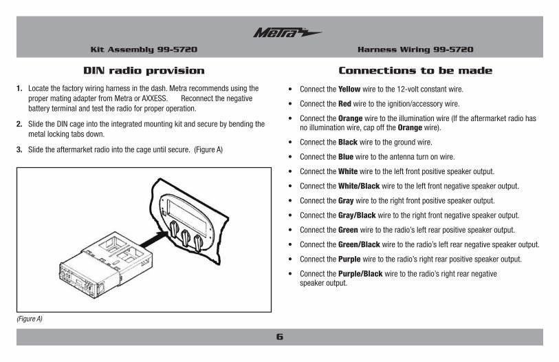
1. Locatethefactorywiringharnessinthedash.MetrarecommendsusingthepropermatingadapterfromMetraorAXXESS. Reconnectthenegativebatteryterminalandtesttheradioforproperoperation.
2. SlidetheDINcageintotheintegratedmountingkitandsecurebybendingthemetallockingtabsdown.
3. Slidetheaftermarketradiointothecageuntilsecure.(FigureA)
(Figure A)
• ConnecttheYellowwiretothe12-voltconstantwire.
• ConnecttheRedwiretotheignition/accessorywire.
• ConnecttheOrangewiretotheilluminationwire(Iftheaftermarketradiohasnoilluminationwire,capofftheOrangewire).
• ConnecttheBlack wiretothegroundwire.
• ConnecttheBluewiretotheantennaturnonwire.
• ConnecttheWhitewiretotheleftfrontpositivespeakeroutput.
• ConnecttheWhite/Blackwiretotheleftfrontnegativespeakeroutput.
• ConnecttheGraywiretotherightfrontpositivespeakeroutput.
• ConnecttheGray/Blackwiretotherightfrontnegativespeakeroutput.
• ConnecttheGreen wiretotheradio’sleftrearpositivespeakeroutput.
• ConnecttheGreen/Blackwiretotheradio’sleftrearnegativespeakeroutput.
• ConnectthePurple wiretotheradio’srightrearpositivespeakeroutput.
• ConnectthePurple/Blackwiretotheradio’srightrearnegative speakeroutput.
Connections to be made
Harness Wiring 99-5720

99-5720
Notes

METRA. The World’s best kits.™ metraonline.com1-800-221-0932 © COPYRIGHT 2004-2013 METRA ELECTRONICS CORPORATION
REV.
2/5
/201
4 I
NST9
9-57
20
KNOWLEDGE IS POWEREnhance your installation and fabrication skills by enrolling in the most recognized and respected mobile electronics school in our industry.Log onto www.installerinstitute.com or call 800-354-6782 for more information and take steps toward a better tomorrow.
Metra recommends MECP certified technicians
INSTALLATION INSTRUCTIONS FOR PART 99-5720
4

APLICACIONES
METRA. The World’s best kits.™ metraonline.com1-800-221-0932 © COPYRIGHT 2004-2013 METRA ELECTRONICS CORPORATION
REV.
1/2
7/20
14
INST
99-5
720
PRECAUCIÓN: Metra recomienda desconectar el terminal negativo de la batería antes de comenzar cualquier instalación. Todos los accesorios, interruptores y, especialmente, las luces indicadoras de airbag deben estar enchufados antes de volver a conectar la batería o comenzar el ciclo de ignición.
NOTA: Remítase a las instrucciones incluidas con el radio de postventa.
INSTRUCCIONES DE INSTALACIÓN PARA LA PIEZA 99-5720
• ProvisiónderadioDIN•Incorporaloscontrolesdeclimadefábricaalainstalación
•A)Kitdemontajeintegradoyarnésdeenergía•B)Arnésdebocinas
CARACTERÍSTICAS DEL KIT
COMPONENTES DEL KIT
•LlavesderemociónMetra86-5618•DestornilladorTorx•Cortador
HERRAMIENTAS REquERIDAS
Ford Escort/Escort ZX2 1997-2002/ZX2 2001-2003, Mercury Tracer 1997-1999
99-5720
BA
CABLEADO Y CONEXIONES DE ANTENAArnésdecableado:
•1997-2002modelos:Incluidoconelkit•Losmodelosde2003:70-5720
Adaptadordeantena:•Noserequiere
(sevendenporseparado)

99-5720
2
Desmontaje del tablero
– FordEscort1997-2002................................................................................... 2-5
– FordEscortZX21997-2002............................................................................ 2-5
– FordZX22001-2003....................................................................................... 2-5
– MercuryTracer1997-1999............................................................................. 2-5
Ensamble del kit
– ProvisiónderadioDIN.........................................................................................6
Arnés de cableado
– Conexionesquesedebenhacer..........................................................................6
Indice
(Figura A)
1. Metalamanodebajodeltablerodelladodelconductorydesengancheelcabledecontroldetemperatura.
2. Usando86-5618deMetra,saqueelpaneldecontrolderadio/climadefábricadeltablero.(FiguraA)
3. Desconecteelarnésdeenergíaparainterruptores,elconectordelaantena,losarnesesdeenergíaparaelradio/lasbocinasyelarnésdelamangueradevacío.
Todos los vehículos

4. Volteeelpaneldecontrolintegradoydesconecteelarnésdecontrolderejillas(“A”),elarnésdecontroldevelocidaddelventilador(“B”)yelarnésdeldesempañador(“C”).(FiguraB)
5. Desengancheelarnésdelinterruptorprincipaldelcostadodelaunidadde
fábrica(estearnésseconectaalarnésdecontroldevelocidaddelventilador,alarnésdecontroldelasrejillasyalarnésdeldesempañador).
Continúa en la página
Todos los vehículos
(Figura B)
A
BC
Vista posterior del panel de control integrado
(Figura C)
3
Desmontaje del tablero 99-5720

4
Desmontaje del tablero 99-5720
6. Pongalosselectoresdecontroldeclimadefábricaenposiciónverticalyjálelosparaquitarlos.(FiguraC)
7. Desengancheelinterruptordecontrolderejillasyretire.Retirelos(2)tornillosdecabezaTorxquesostienenelinterruptordelcontroldetemperaturayelinterruptordelcontroldevelocidaddeventiladoryretire.(FiguraD)
8. MontelosinterruptoresenlaparteposteriordelkitdemontajeintegradoconlosmismostornillosdecabezaTorx.(FiguraE)
9. Sosteniendolosselectoresdelcontroldeclimaenposiciónvertical,insértelosenlospostesdelosinterruptoresmontadosyasegúrelos.(FiguraF)
Todos los vehículos
(Figura E)(Figura D) (Figura F)

5
Desmontaje del tablero 99-5720
Todos los vehículos
(Figura H)(Figura G)
10.Corteyretirelasporcionessombreadasdelrebordedelsubtablero.(FiguraG)
PRECAUCIÓN: Nota, la asamblea no encajará en el sub-guión si este paso no se hace.
11.Hagatodaslasconexionesdecableadoalkitdemontajeintegradoycoloqueapresiónelensambleenelsubtablero.(FiguraH)
12.Metalamanodebajodeltablerodelladodelconductoryvuelvaaconectarelcabledecontroldetemperatura.
Continuará al ensamble del kit

6
Ensamble del kit 99-5720
Provisión de radio DIN
1. Ubiqueelarnésdelcableadodefábricaeneltablero.MetrarecomiendausareladaptadordeacoplamientoadecuadodeMetraoAXXESS.Vuelvaaconectarelterminalnegativodelabateríaypruebelaunidadparaverificarquefuncionecorrectamente.
2. DeslicelarejaDINenelkitintegradodemontajeysujételadoblandohaciaabajolaspestañasdemetal.
3. Deslicelaunidadcentraldemercadosecundarioenlarejahastaquequedefirme.(FiguraA)
(Figura A)
• ConecteelcableAmarilloconelcableconstante/dememoriadelradio.
• ConecteelcableRojoconelcabledeaccesoriosdelradio.
• ConecteelcableAnaranjado/Blancoalcabledeiluminacióndelradiodemercadosecundario.Sielradiodemercadosecundarionotienecabledeiluminación,cubraconcintaelcableAnaranjado/Blanco.
• Conecteelcable Negro conelcabledetierradelradio.
• ConecteelcableAzul conelencendidodelaantenadelradio.
• Conecteelcable Blancoconelcabledelabocinaizquierdafrontal(+)delradio.
• ConecteelcableBlanco/Negroconelcabledelabocinaizquierda frontal(-)delradio.
• ConecteelcableGrisconelcabledelabocinaderechafrontal(+)delradio.
• ConecteelcableGris/Negroconelcabledelabocinaderecha frontal(-)delradio.
• ConecteelcableVerdeconelcabledelabocinaizquierdadeatrás(+)delradio.
• ConecteelcableVerde/Negroconelcabledelabocinaizquierdade atrás(-)delradio.
• ConecteelcablePúrpuraconelcabledelabocinaderechade atrás(+)delradio.
• Conecteelcable Púrpura/Negroconelcabledelabocinaderechadeatrás(-)delradio.
Conexiones que se deben hacer
Arnés de cableado 99-5720

99-5720
Notas

METRA. The World’s best kits.™ metraonline.com1-800-221-0932 © COPYRIGHT 2004-2013 METRA ELECTRONICS CORPORATION
REV.
1/2
7/20
14
INST
99-5
720
KNOWLEDGE IS POWEREnhance your installation and fabrication skills by enrolling in the most recognized and respected mobile electronics school in our industry.Log onto www.installerinstitute.com or call 800-354-6782 for more information and take steps toward a better tomorrow.
Metra recomienda técnicos con certificación del Programa de Certificación en Electrónica Móvil (Mobile Electronics Certification Program, MECP).
EL CONOCIMIENTO ES PODERMejoresushabilidadesdeinstalaciónyfabricacióninscribiéndoseenlaescueladedispositivoselectrónicosmóvilesmásreconocidayrespetadadenuestraindustria.Regístreseenwww.installerinstitute.comollameal800-354-6782paraobtenermásinformaciónyavancehaciaunfuturomejor.
INSTRUCCIONES DE INSTALACIÓN PARA LA PIEZA 99-5720