installation instructions for the issue 5 micro switch ... · micro switch heavy duty limit switch...
TRANSCRIPT
Sensing and Internet of Things
mWARNINGPERSONAL INJURYDO NOT USE these products as safety or emergency stop devices, or in any other application where failure of the product could result in personal injury.
Failure to comply with these instructions could result in death or serious injury.
MOUNTING All MICRO SWITCH Heavy Duty Limit Switches (HDLS) have exactly the same mounting dimensions. They may be mounted by either of two methods: (a) use two #10 screws from the front, or (b) use two #10-32 UNF screws from the back. The HDLS Series offers the advantage of front mount construction. The electrician will find a complete switch, with no parts missing and ample wiring space.
With plug-in construction, wiring and conduit connection is made to the base receptacle. This feature also reduces downtime, since the plug-in unit can be removed without disconnecting wiring or conduit.
To mount either type of HDLS switch, tighten mounting screws, tighten the plug-in unit or cover screws, and make sure conduit section is sealed. Use of sealant (Teflon® tape, pipe dope, etc.) is recommended to seal conduit connection. Torque 1.4 Nm to 1.8 Nm [12 in-lb to 16 in-lb].
Because of moisture condensation, it is not advisable to mount the switch upside down or at the low point of conduit runs.
Sealing IP65/IP66/IP67
Enclosure type NEMA 1, 3, 4, 4X, 6, 6P, 12, 13
Rated Operational Voltages (Ue) and Currents (IE)
Ue Ie
120 Vac 6 A
600 Vac 1.2 A
125 Vdc 0.22 A
250 Vdc 0.11 A
Installation Instructions for theMICRO SWITCH Heavy Duty Limit Switch Series
Issue 5
81116
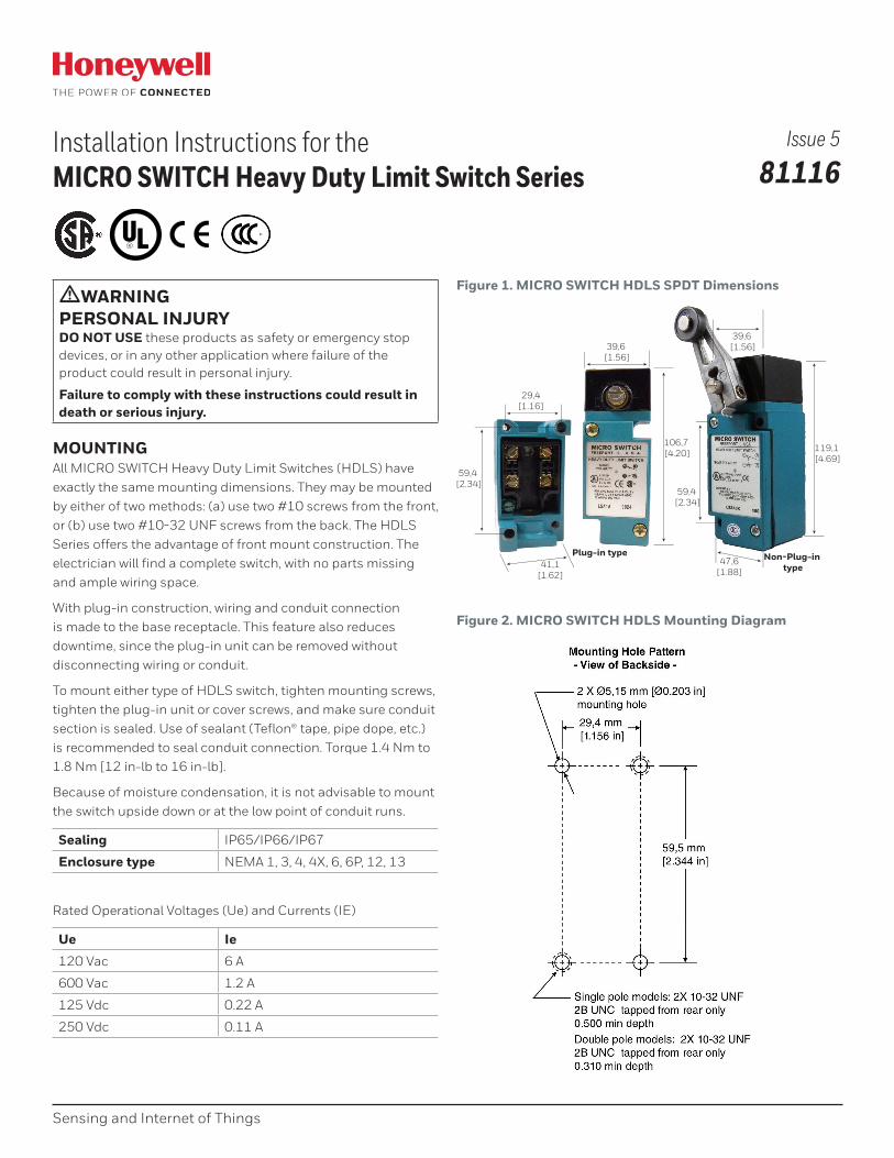
Figure 1. MICRO SWITCH HDLS SPDT Dimensions
106,7 [4.20]
39,6 [1.56]
41,1[1.62]
59,4 [2.34]
29,4[1.16]
119,1 [4.69]
39,6 [1.56]
59,4 [2.34]
47,6[1.88]
Plug-in type Non-Plug-in type
Figure 2. MICRO SWITCH HDLS Mounting Diagram
2 sensing.honeywell.com
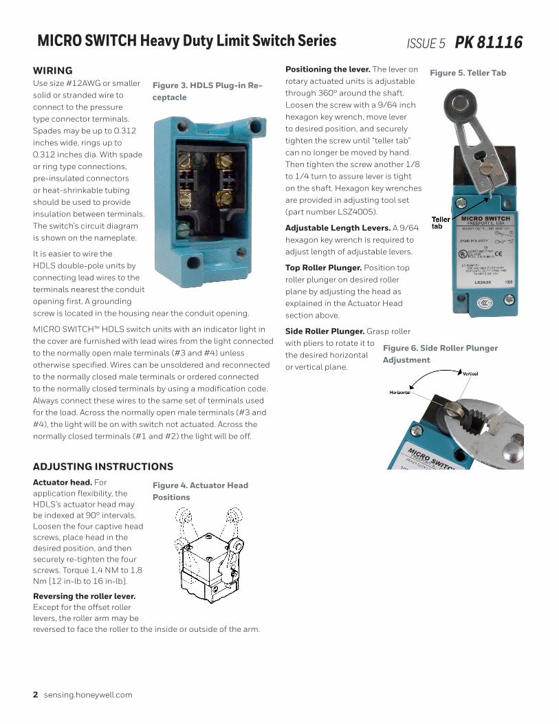
MICRO SWITCH Heavy Duty Limit Switch Series ISSUE 5 PK 81116WIRING Use size #12AWG or smaller solid or stranded wire to connect to the pressure type connector terminals. Spades may be up to 0.312 inches wide, rings up to 0.312 inches dia. With spade or ring type connections, pre-insulated connectors or heat-shrinkable tubing should be used to provide insulation between terminals. The switch’s circuit diagram is shown on the nameplate.
It is easier to wire the HDLS double-pole units by connecting lead wires to the terminals nearest the conduit opening first. A grounding screw is located in the housing near the conduit opening.
MICRO SWITCH™ HDLS switch units with an indicator light in the cover are furnished with lead wires from the light connected to the normally open male terminals (#3 and #4) unless otherwise specified. Wires can be unsoldered and reconnected to the normally closed male terminals or ordered connected to the normally closed terminals by using a modification code. Always connect these wires to the same set of terminals used for the load. Across the normally open male terminals (#3 and #4), the light will be on with switch not actuated. Across the normally closed terminals (#1 and #2) the light will be off.
ADJUSTING INSTRUCTIONSActuator head. For application flexibility, the HDLS’s actuator head may be indexed at 90° intervals. Loosen the four captive head screws, place head in the desired position, and then securely re-tighten the four screws. Torque 1,4 NM to 1,8 Nm [12 in-lb to 16 in-lb].
Reversing the roller lever. Except for the offset roller levers, the roller arm may be reversed to face the roller to the inside or outside of the arm.
Positioning the lever. The lever on rotary actuated units is adjustable through 360° around the shaft. Loosen the screw with a 9/64 inch hexagon key wrench, move lever to desired position, and securely tighten the screw until “teller tab” can no Ionger be moved by hand. Then tighten the screw another 1/8 to 1/4 turn to assure lever is tight on the shaft. Hexagon key wrenches are provided in adjusting tool set (part number LSZ4005).
Adjustable Length Levers. A 9/64 hexagon key wrench is required to adjust length of adjustable levers.
Top Roller Plunger. Position top roller plunger on desired roller plane by adjusting the head as explained in the Actuator Head section above.
Side Roller Plunger. Grasp roller with pliers to rotate it to the desired horizontal or vertical plane.
Figure 3. HDLS Plug-in Re-ceptacle
Figure 4. Actuator Head Positions
Figure 5. Teller Tab
Figure 6. Side Roller Plunger Adjustment

Sensing and Internet of Things 3
MICRO SWITCH Heavy Duty Limit Switch Series ISSUE 5 PK 81116CHANGING DIRECTION OF ACTUATIONSide Rotary. LSM (center neutral) and LSN (maintained) HDLS listings operate in both directions and cannot be changed. Listings with the first three letters LSA, LSH, LSL, LSP, LSU, and LSR may be changed to operate clockwise, counterclockwise, or both. NOTE: Instructions for adjusting switch operation are cast into the hinged cover (Figure 7). To change, follow these steps:
1. Loosen the head screws and remove the head from the switch housing.
2. On the bottom of the head, insert a screwdriver in slot provided (Figure 8) and lift open hinged cover.
3. Referring to Figures 7/8/9, slide cam all the way back, so cam is free to rotate on the shaft.
4. Using a screwdriver or similar tool, rotate cam to desired actuating position (Figures 10, 11, and 12.)
5. Slide cam all the way forward to its original position, and close hinged cover.
6. Replace operating head on switch housing and securely tighten head screws. Torque 1,4 NM to 1,8 Nm [12 in-lb to 16 in-lb].
Figure 7. MICRO SWITCH HDLS Cam Slide
Figure 8. MICRO SWITCH HDLS Side Rotary Actuator Head Terminology
Figure 9. MICRO SWITCH HDLS
Figure 10. MICRO SWITCH HDLS Cam Lobes for CW and CCW
Figure 11. MICRO SWITCH HDLS Cam Lobe for CW
Figure 12. MICRO SWITCH HDLS Cam Lobe for CCW

4 sensing.honeywell.com
MICRO SWITCH Heavy Duty Limit Switch Series ISSUE 5 PK 81116 Top Rotary. Follow these steps to change operating direction of LSB type switches:
1. Loosen head screws and remove head from the switch housing.
2. From bottom of head grasp end of pin plunger and remove pin (Figure 13). It may be necessary to rotate actuating shaft to expose end of pin plunger.
3. Refer to Figure 14 and select correct pin plunger position for desired direction of actuation.
4. Insert the pin plunger in the position providing desired direction of actuation.
5. Replace the operating head on switch housing and securely tighten head screws (Torque 1,4 Nm to 1,8 Nm [12 in-lb to 16 in-lb]).
Figure 13. MICRO SWITCH HDLS Top Rotary Actuator
Figure 14. MICRO SWITCH HDLS Top Rotary Actuation Diagram
GRAVITY RETURN HDLSListings beginning with LSS are gravity return devices. During installation and setup, note the following:
1. Operate and release points exchange locations when shaft is rotated 180° (Figure 15).
2. Switch is near operate-release points when shaft slot is parallel to switch’s long axis (Figure 15).
3. The switch should be installed so that the weight of the actuator returns to the switch’s free position.
Figure 15. MICRO SWITCH HDLS Gravity Return Operate and Release Points
Replacement partsWhen replacing parts, please follow the instructions included with the part.
Should a specific switch catalog listing not appear in this parts list, contact nearest Honeywell Sensing and Control authorized distributor or Honeywell sales office.
For ease of making switch adjustments, order LSZ4005 (lever and switch adjusting tool set). This set consists of a special 3/32-inch open wrench and necessary hexagon key wrenches to adjust all types of levers.
Replacement Levers. To order replacement levers, order the same part number that is metal stamped on either lever or lever hub. For additional options, see Table 7 of Heavy-Duty Limit Switch (HDLS) data sheet available on www.sensing.honeywell.com or follow this link: https://sensing.honeywell.com/honeywell-sensing-micro-switch-hdls-limit-product-sheet-002345-10-en.pdf

Sensing and Internet of Things 5
MICRO SWITCH Heavy Duty Limit Switch Series ISSUE 5 PK 81116Table 1. MICRO SWITCH HDLS Plug-in Type Replacement Components
Catalog Listing*
on Switch Nameplate
Complete Plug-in Unit
Less Base Receptacle
Plug-in Base
Recept. Only
Operating Head Only
Contact Block (Basic Switch Only)
LSA1A LSZ7A1A LSZ4001 LSZ1A LSZ3A
LSA1J LSZ7A1J LSZ4001 LSZ1A LSZ3J
LSA2B LSZ7A2B LSZ4002 LSZ1A LSZ3B
LSB1A LSZ7B1A LSZ4001 LSZ1B LSZ3A
LSC1A LSZ7C1A LSZ4001 LSZ1C LSZ3A
LSC1J LSZ7C1J LSZ4001 LSZ1C LSZ3J
LSD1A LSZ7D1A LSZ4001 LSZ1D LSZ3A
LSD1J LSZ7D1J LSZ4001 LSZ1D LSZ3J
LSD2B LSZ7D2B LSZ4002 LSZ1D LSZ3B
LSE1A LSZ7E1A LSZ4001 LSZ1E LSZ3A
LSE1J LSZ7E1J LSZ4001 LSZ1E LSZ3J
LSE2B LSZ7E2B LSZ4002 LSZ1E LSZ3B
LSF1A LSZ7F1A LSZ4001 LSZ1F LSZ3A
LSF1J LSZ7F1J LSZ4001 LSZ1F LSZ3J
LSF2B LSZ7F2B LSZ4002 LSZ1F LSZ3B
LSH1A LSZ7H1A LSZ4001 LSZ1H LSZ3A
LSH1J LSZ7H1J LSZ4001 LSZ1H LSZ3J
LSH2B LSZ7H2B LSZ4002 LSZ1H LSZ3B
LSJ1A-7A LSZ7J1A-7A LSZ4001 LSZ1JGA LSZ3A
LSJ1A-7M LSZ7J1A-7M LSZ4001 LSZ1JGM LSZ3A
LSJ2B-7A LSZ7J2B-7A LSZ4002 LSZ1JGA LSZ3B
LSJ2B-7M LSZ7J2B-7M LSZ4002 LSZ1JGM LSZ3B
LSK1A-8A LSZ7K1A-8A LSZ4001 LSZ1KHA LSZ3A
LSK2B-8A LSZ7K2B-8A LSZ4002 LSZ1KHA LSZ3B
LSL2C LSZ7L2C LSZ4002 LSZ1L LSZ3C
LSM2D LSZ7M2D LSZ4002 LSZ1M LSZ3C
LSN1A LSZ7N1A LSZ4001 LSZ1N **
LSN2B LSZ7N2B LSZ4002 LSZ1N **
LSP1A LSZ7P1A LSZ4001 LSZ1P LSZ3A
LSP1J LSZ7P1J LSZ4001 LSZ1P LSZ3J
LSP2B LSZ7P2B LSZ4002 LSZ1P LSZ3B
LSR1A LSZ7R1A LSZ4001 LSZ1R LSZ3A
LSR1J LSZ7R1A LSZ4001 LSZ1R LSZ3J
LSH2B LSZ7R2B LSZ4002 LSZ1R LSZ3B
LSU1A LSZ7U1A LSZ4001 LSZ1U LSZ3A
LSV1A LSZ7V1A LSZ4001 LSZ1V LSZ3J
LSV1J LSZ7V1J LSZ4001 LSZ1V LSZ3A
LSV5A LSZ7V5A LSZ4001 LSZ1V LSZ3A
LSV8A LSZ7V8A LSZ4001 LSZ1V LSZ3A
Table 2. MICRO SWITCH HDLS Non-Plug-in Type Replacement Components
Catalog Listing on Switch Nameplate
Operating Head Only
Contact Block (Basic Switch Only)
LSA3K LSZ1A LSZ3K
LSA4L LSZ1A LSZ3L
LSB3K LSZ1B LSZ3K
LSB4L LSZ1B LSZ3L
LSC3K LSZ1C LSZ3K
LSC4L LSZ1C LSZ3L
LSD3K LSZ1D LSZ3K
LSD4L LSZ1D LSZ3L
LSE3K LSZ1E LSK3K
LSE4L LSZ1E LSZ3L
LSF3K LSZ1F LSZ3K
LSF4L LSZ1F LSZ3L
LSG3K LSF1G **
LSH3K LSZ1H LSZ3K
LSH4L LSZ1H LSZ3 L
LSJ3K-7A LSZ1JGA LSZ3 L
LSJ3K-7M LSZ1JGM LSZ3 K
LSJ4L-7A LSZ1JGA LSZ3 L
LSJ4L-7M LSZ1JGM LSZ3 L
LSK3K-8A LSZ1KHA LSZ3 K
LSK4L-8A LSZ1KHA LSZ3 L
LSL4M LSZ1L LSZ3 M
LSM4N LSZ1M LSZ3M
LSN3K LSZ1N **
LSN4L LSZ1N * *
LSP3K LSZ1P LSZ3 K
LSP4L LSZ1P LSZ3 L
LSR3K LSZ1R LSZ3 K
LSR4L LSZ1R LSZ3 L
LSU3K LSZ1U LSZ3 K
LSU4L LSZ1U LSZ3L
*Only the listing portion which determines the replacement part is shown. Listings with -7A, -7M, or -8A are complete listings.
**Not user-replaceable.
6 sensing.honeywell.com
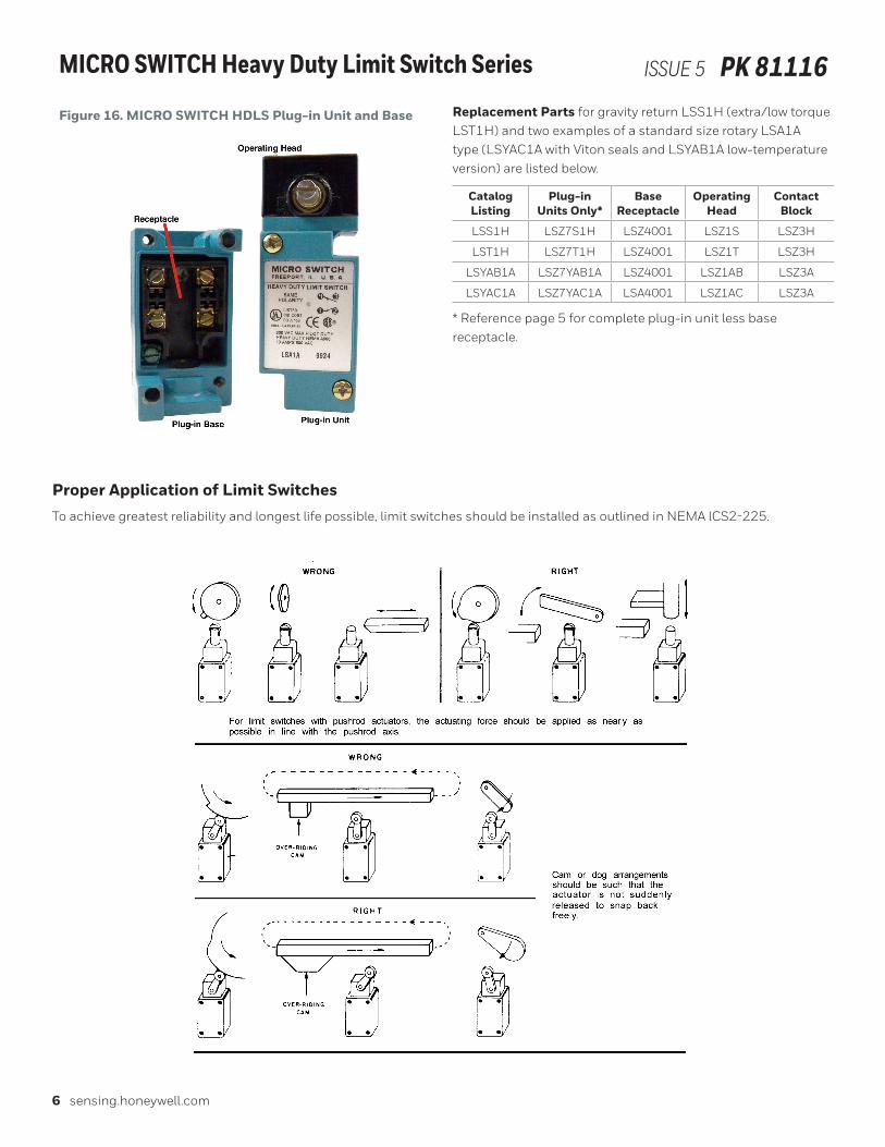
MICRO SWITCH Heavy Duty Limit Switch Series ISSUE 5 PK 81116Figure 16. MICRO SWITCH HDLS Plug-in Unit and Base Replacement Parts for gravity return LSS1H (extra/low torque
LST1H) and two examples of a standard size rotary LSA1A type (LSYAC1A with Viton seals and LSYAB1A low-temperature version) are listed below.
Catalog Listing
Plug-in Units Only*
Base Receptacle
Operating Head
Contact Block
LSS1H LSZ7S1H LSZ4001 LSZ1S LSZ3H
LST1H LSZ7T1H LSZ4001 LSZ1T LSZ3H
LSYAB1A LSZ7YAB1A LSZ4001 LSZ1AB LSZ3A
LSYAC1A LSZ7YAC1A LSA4001 LSZ1AC LSZ3A
* Reference page 5 for complete plug-in unit less base receptacle.
Proper Application of Limit SwitchesTo achieve greatest reliability and longest life possible, limit switches should be installed as outlined in NEMA lCS2-225.

81116-5-EN | 5 | 02/19© 2019 Honeywell International Inc. All rights reserved.
MICRO SWITCH Heavy Duty Limit Switch Series ISSUE 5 PK 81116
Honeywell Sensing and Internet of Things9680 Old Bailes Road
Fort Mill, SC 29707
honeywell.com
Warranty/RemedyHoneywell warrants goods of its manufacture as being free of defective materials and faulty workmanship during the applicable warranty period. Honeywell’s standard product warranty applies unless agreed to otherwise by Honeywell in writing; please refer to your order acknowledgment or consult your local sales office for specific warranty details. If warranted goods are returned to Honeywell during the period of coverage, Honeywell will repair or replace, at its option, without charge those items that Honeywell, in its sole discretion, finds defective. The foregoing is buyer’s sole remedy and is in lieu of all other warranties, expressed or implied, including those of merchantability and fitness for a particular purpose. In no event shall Honeywell be liable for consequential, special, or indirect damages.
While Honeywell may provide application assistance personally, through our literature and the Honeywell web site, it is buyer’s sole responsibility to determine the suitability of the product in the application.
Specifications may change without notice. The information we supply is believed to be accurate and reliable as of this writing. However, Honeywell assumes no responsibility for its use.