installation instructions for the - unicosystem.com · part no. description m1218+xx,cb fan coil...
TRANSCRIPT
Bulletin 30-38 / March 2009
© Copyright 2008 Unico, Inc.
General
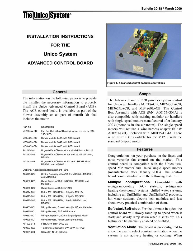
The information on the following pages is to provide the installer the necessary information to properly install the Unico Advanced Control Board (ACB). The ACB control board is available as part of the blower assembly or as part of retrofit kit that includes the motor.
Part no. Description
M1218+xx,CB Fan Coil Unit with ACB control, where ‘xx’ can be ‘AC’, ‘HP’, ‘CW’.
MB2430L+CB Blower Module, 2430, with ACB control
MB3642L+CB Blower Module, 3642, with ACB control
MB4860L+CB Blower Module, 4860, with ACB control
A01017-001 Upgrade Kit, ACB control box with MP Motor, M1218
A01017-002 Upgrade Kit, ACB control box and 1/2 HP MP Motor, MB2430L
A01017-003 Upgrade Kit, ACB control Box and 1 HP MP Motor, MB3642L and MB4860L
Optional Accessories/Replacement Parts
A00175-G04 Control Box Assy with ACB (for MB2430L, MB3642L and MB4860L)
A00980-G01 Circuit Board, ACB (for MB2430L, MB3642L and MB4860L)
A00980-G02 Circuit Board, ACB (for M1218)
A00974-001 Motor, MP, 1750 RPM, 1/3 hp (for M1218)
A00975-001 Motor, MP, 1750 RPM, 1/2 hp (for MB2430L)
A00975-002 Motor, MP, 1750 RPM, 1 hp (for MB3642L and MB4860L)
A00983-G01 Wiring Harness, Power Leads (for US and Canada)
A00985-G01 Wiring Harness, PCB to MP motor
A00987-G01 Wiring Adapter Kit, ACB to Single-Speed Motor
A00995-G01 Wiring Harness, Power Leads (for Europe)
A01002-013 Fuse, Slow-blow, 2AG, 3A
A00057-G03 Transformer, 208/230V-24V, 50VA (for PCB)
A00351-003 Capacitor, 10 μF, 370VAC
Scope
The Advanced control PCB provides system control for Unico air handlers M1218+CB, MB2430L+CB, MB3624L+CB, and MB4860L+CB. The Control Box Assembly with ACB (P/N: A00175-G04A) is also compatible with existing modular air handlers with single-speed motors manufactured after January 2003 (motor is in the airstream). The single-speed motors will require a wire harness adapter (Kit #: A00987-G01), included with A00175-G04A. There is no retrofit kit available for the M1218 with the standard 3-speed motor.
Features
Congratulations on your purchase on the finest and most versatile fan control on the market. This control board is compatible with the Unico two-speed MP motors and Unico single speed motors (manufactured after January 2003). The control board comes standard with the following features.
Multiple configurations. Compatible with refrigerant-cooling (AC) systems; refrigerant-heating (heat-pump) systems; chilled water systems, including all UniChiller and UniChillerRC products, hot water systems, electric heat modules, and just about every practical combination of them.
Soft-start/Soft-stop. For the ultimate in quiet, the control board will slowly ramp up to speed when it starts and slowly ramp down when it shuts off. This feature can be manually enabled or disabled.
Ventilation Mode. The board is pre-configured to allow the user to select constant ventilation when the system is not actively heating or cooling. When
Figure 1. Advanced control board in control box
INSTALLATION INSTRUCTIONS
FOR THE
Unico System
ADVANCED CONTROL BOARD
Bulletin 30-38 — Page 2
© Copyright 2008 Unico, Inc.
used with the 2-speed MP motors, the ventilation speed has the further benefit of low operating cost as it uses only 1/4th of full-speed power. This is nearly the same as a DC motor without the extra costs. Other speed reduction technologies, using variable-speed controls, still use 3/4ths of full power.
Simplified Wiring. The control box was developed with the contractor in mind. All wiring terminals are clearly labeled and are designed for point-to-point wiring (one wire per terminal). In addition, we added a feature that allows you to make your terminal connects THEN slip the wire cable into the slotted bushing. Never again, will you have to disconnect and re-wire the board because the cable was not pre-inserted through the bushings.
Accessories. The control board provides separate relays and contacts to energize a separate Electronic Air Cleaner (EAC) or UV light. We also provide a relay to energize a humidifier with a separate humidistat input for proper control. We even provide a feature to allow the humidistat to control the fan so that humidity can be added even if the fan is not already on. And, of course, the control is smart enough to sense when the system is trying to cool, so that humidity is not added if in cooling mode.
Designed for the Unico Electric Heat Module. When using the Unico Electric Heat Module with the Unico heat pump, we require that third step of electric heaters is not energized at the same time as the electric heat. Previously, we required that a field installed relay or ther-mostat be installed to prevent this from occur-ring. The control box provides this feature, saving both time and costs. At the same time, the control board is designed for multiple stage thermostats to gradually turn on the electric heat after the heat pump; thereby, improving the efficiency of the heat pump while maintaining the greatest capacity.
Designed for the UniChillerRC. The control is designed to operate the Chiller from the thermostat. And, for multiple thermostat systems, the control boards can communicate, making one the master the others slaves for the
best system control available. The board, then, knows whether the chiller is making hot or cold water and turns on the blower as appropriate.
Designed for Hot Water Heating systems. The control allows you to select whether the hot water heating is primary, secondary or emergency heat for single or multi-staged systems. Also, a timer function is included to operate the hot water pump when used with potable water ‘combo’ systems on a periodic basis; this prevents the water from becoming stagnant over time.
2-Speed condenser Compatibility. Two speed condensers with multi-stage thermostats can be used with the board, with an option to operate the first stage at either high or low speed.
Quality Design and Manufacture. The board itself is made from high quality electronic parts. The board includes a conformal coating to eliminate problems with humidity, moisture, and dust. It is resistant to high voltage discharges (lightening resistant, not lightening proof – which, of course, nothing is!). It is fully certified to UL standards and listed as part of the Unico Blower Module with ETL. Every board is fully tested.
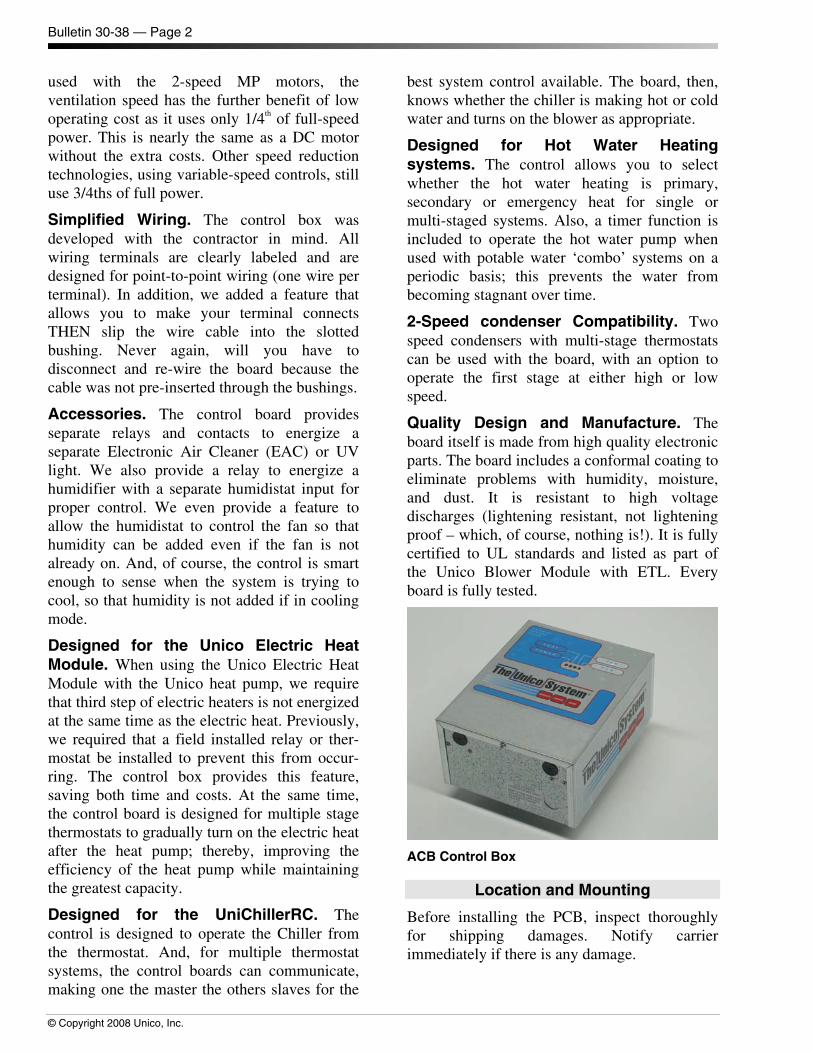
ACB Control Box
Location and Mounting
Before installing the PCB, inspect thoroughly for shipping damages. Notify carrier immediately if there is any damage.
Bulletin 30-38 — Page 3
Copyright 2008 Unico, Inc.
The control box can be installed in one of two positions on the modular air handler (Figure 2). Chose the position that allows the best access.
Control BoxLocation
Blower Module
Plenum
Figure 2. Control Box Mounting Locations.
CAUTION The control box must be screwed to the air handler to provide proper ground for the motor.
The large knock-out on the air handler must be removed to allow the motor cable connector to protrude into the air handler space.
WIRING
WARNING!
DISCONNECT ELECTRICAL SUP-PLY BEFORE WIRING UNIT TO PREVENT INJURY OR DEATH FROM ELECTRICAL SHOCK.
All electrical wiring must comply with all local codes and ordinances. Use a separate 1 ph-208/240V-60 Hz power supply with appropriate amp fuse or breaker and wire gauge for the specified amperage.
Once the control box is mounted, the motor can be connected from inside the air handler. Remove the appropriate air handler access panel. Connect the 9-pin motor connector to the mating connector on control box. Push firmly; be sure the connector is seated.
Connect the following using the wiring drawing for your particular system shown in Table 1.
1) Thermostat to the stat terminal block on the PCB
2) Outdoor unit to condenser terminal block on the PCB
3) Air cleaner, humidity system, boiler, valve, or pump to the output terminal block on the PCB
4) Electric heat control module to the electric heat terminal block on the PCB
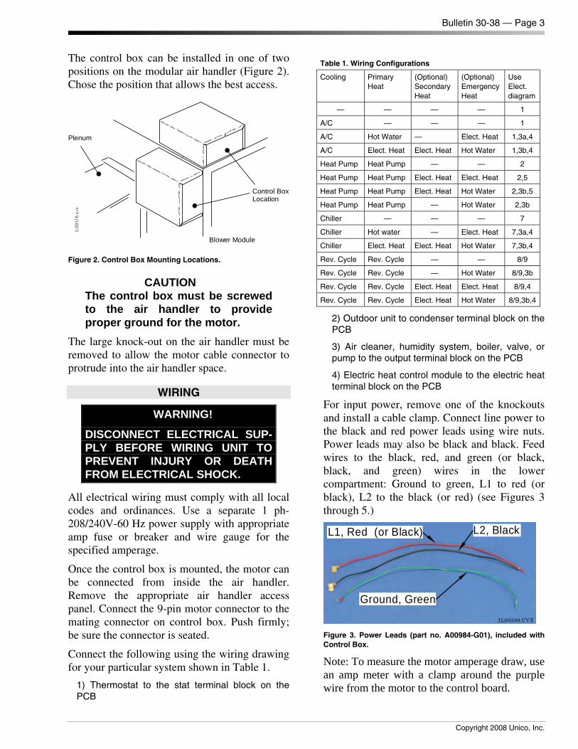
For input power, remove one of the knockouts and install a cable clamp. Connect line power to the black and red power leads using wire nuts. Power leads may also be black and black. Feed wires to the black, red, and green (or black, black, and green) wires in the lower compartment: Ground to green, L1 to red (or black), L2 to the black (or red) (see Figures 3 through 5.)
L1, Red (or Black) L2, Black
Ground, Green
IL00398.CVX Figure 3. Power Leads (part no. A00984-G01), included with Control Box.
Note: To measure the motor amperage draw, use an amp meter with a clamp around the purple wire from the motor to the control board.
Table 1. Wiring Configurations
Cooling Primary Heat
(Optional) Secondary Heat
(Optional) Emergency Heat
Use Elect. diagram
— — — — 1
A/C — — — 1
A/C Hot Water — Elect. Heat 1,3a,4
A/C Elect. Heat Elect. Heat Hot Water 1,3b,4
Heat Pump Heat Pump — — 2
Heat Pump Heat Pump Elect. Heat Elect. Heat 2,5
Heat Pump Heat Pump Elect. Heat Hot Water 2,3b,5
Heat Pump Heat Pump — Hot Water 2,3b
Chiller — — — 7
Chiller Hot water — Elect. Heat 7,3a,4
Chiller Elect. Heat Elect. Heat Hot Water 7,3b,4
Rev. Cycle Rev. Cycle — — 8/9
Rev. Cycle Rev. Cycle — Hot Water 8/9,3b
Rev. Cycle Rev. Cycle Elect. Heat Elect. Heat 8/9,4
Rev. Cycle Rev. Cycle Elect. Heat Hot Water 8/9,3b,4
Bulletin 30-38 — Page 4
© Copyright 2008 Unico, Inc.
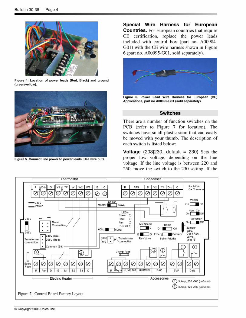
Figure 4. Location of power leads (Red, Black) and ground (green/yellow).
Figure 5. Connect line power to power leads. Use wire nuts.
Special Wire Harness for European Countries. For European countries that require CE certification, replace the power leads included with control box (part no. A00984-G01) with the CE wire harness shown in Figure 6 (part no. A00995-G01, sold separately).
Figure 6. Power Lead Wire Harness for European (CE) Applications, part no A00995-G01 (sold separately).
Switches
There are a number of function switches on the PCB (refer to Figure 7 for location). The switches have small plastic stem that can easily be moved with your thumb. The description of each switch is listed below:
Voltage (208|230, default = 230) Sets the proper low voltage, depending on the line voltage. If the line voltage is between 220 and 250, move the switch to the 230 setting. If the
Figure 7. Control Board Factory Layout
Bulletin 30-38 — Page 5
Copyright 2008 Unico, Inc.
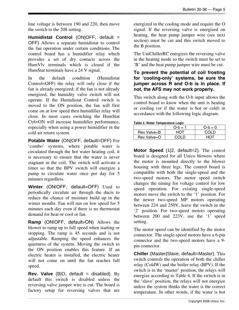
line voltage is between 190 and 220, then move the switch to the 208 setting.
Humidistat Control (ON|OFF, default = OFF) Allows a separate humidistat to control the fan operation under certain conditions. The control board has a humidifier relay which provides a set of dry contacts across the HumVlv terminals which is closed if the HumStat terminals have a 24 V signal.
In the default condition (Humidistat Control=OFF) the relay will only close if the fan is already energized; if the fan is not already energized, the humidity valve switch will not operate. If the Humidistat Control switch is moved to the ON position, the fan will first come on at low speed then humidifier relay will close. In most cases switching the HumStat Ctrl=ON will increase humidifier performance, especially when using a power humidifier in the cold air return system.
Potable Water (ON|OFF, default=OFF) For ‘combo’ systems, where potable water is circulated through the hot water heating coil, it is necessary to ensure that the water is never stagnant in the coil. The switch will activate a timer so that the BPV switch will energize a pump to circulate water once per day for 5 minutes regardless.
Winter (ON|OFF, default=OFF) Used to periodically circulate air through the ducts to reduce the chance of moisture build up in the winter months. Fan will run on low speed for 5 minutes each day even if there is no thermostat demand for heat or cool or fan.
Ramp (ON|OFF, default=ON) Allows the blower to ramp up to full speed when starting or stopping. The ramp is 45 seconds and is not adjustable. Ramping the speed enhances the quietness of the system. Moving the switch to the ON position enables this feature. If an electric heater is installed, the electric heater will not come on until the fan reaches full speed.
Rev. Valve (B|O, default = disabled). By default this switch is disabled unless the reversing valve jumper wire is cut. The board is factory setup for reversing valves that are
energized in the cooling mode and require the O signal. If the reversing valve is energized on heating, the heat pump jumper wire (see next section) must be cut and this switch moved to the B position.
The UniChillerRC energizes the reversing valve in the heating mode so the switch must be set to ‘B’ and the heat pump jumper wire must be cut.
To prevent the potential of coil frosting for ‘cooling-only’ systems, be sure the jumper across R and O-b is in place. If not, the AFS may not work properly.
This switch along with the O-b input allows the control board to know when the unit is heating or cooling (or if the water is hot or cold) in accordance with the following logic diagram.
Table 2. Water Temperature Logic
O-b = 1 O-b = 0 Rev.Valve=B HOT COLD Rev.Valve=O COLD HOT
Motor Speed (1|2, default=2). The control board is designed for all Unico blowers where the motor is mounted directly to the blower housing with three legs. The control board is compatible with both the single-speed and the two-speed motors. The motor speed switch changes the timing for voltage control for low speed operation. For existing single-speed motors move the switch to the ‘1’ position. For the newer two-speed MP motors operating between 224 and 250V, leave the switch in the ‘2’ position. For two-speed motors operating between 200 and 223V, use the ‘1’ speed setting.
The motor speed can be identified by the motor connector. The single-speed motors have a 6-pin connector and the two-speed motors have a 9-pin connector.
Chiller (Master|Slave, default=Master). This switch controls the operation of both the chiller relay (ColdW) and the boiler relay (BPV). If the switch is in the ‘master’ position, the relays will energize according to Table 4. If the switch is in the ‘slave’ position, the relays will not energize unless the system thinks the water is the correct temperature. In other words, if the water is hot

Bulletin 30-38 — Page 6
© Copyright 2008 Unico, Inc.
and the thermostat calls for cooling, the ColdW relay will not energize; however, the fan will still come on which will at least provide ventilation without heating the room when you need cooling.
Boiler Priority (Emerg|Primary, default = Primary). This switch controls when the boiler and chiller relays are energized. The functional chart is shown in table 3. Refer to Diagram 3 for proper wiring.
Table 3. Boiler Priority Switch function chart
Boiler Priority=Primary Boiler Priority=Emerg BPV is energized with ‘W’ (call for heat) ColdW is energized with ‘Y’ (call for cooling)
BPV is energized only with ‘E’ (call for emergency heat) ColdW is energized with ‘Y’ or ‘W’ (call for cooling or heating)
Note: ‘E’, ‘W’, ‘W2’ always energize the electric heater terminals, regardless of this switch.
Hz (50|60, default=60). This switch controls the timing and voltage function when running in low speed when operated using 50 or 60 Hz power supply.
Jumpers
There are several jumpers on the PCB that are provided to make the most common wiring applications easier. These must be removed for some applications. The description of each jumper is listed below:
R – Ob (thermostat block) jumper is required for all cooling-only systems. The board is preconfigured for heat-pump systems that energize the reversing valve in the cooling mode (i.e. require ‘O’). The control senses the signal on the O-b terminal to determine whether it is in cooling or heating mode. Therefore, for cooling-only systems it is necessary to provide this jumper so the control knows it is in the cooling mode. For heat pump systems or UniChillerRC systems, this jumper must be removed.
Y2 – Y1 (thermostat block) jumper is used for the convenience of the installer when using a single-speed condenser. If the thermostat calls for cooling at the Y2 terminal the fan speed is
high, whereas, at the Y1 terminal the fan speed is low. The jumper forces the fan to run on high during all cooling modes. Therefore, the jumper is in place to allow the installer the ability to use either terminal. For two-stage condensers, this jumper must be removed.
R – Aqua (accessories block) allows the hot water relay to function without an optional aquastat. If an aquastat is used, this jumper must be removed.
Heat Pump Jumper Wire (permanent jumper on board) disables the Reversing Valve switch so that it is permanently in the ‘O’ position. For systems that have a reversing valve that is energized in heating and requires a ‘B’ connection, cut the jumper with a wire snips and move the Rev.Valve switch to ‘B’. This wire jumper must be cut for proper UniChillerRC operation.
Bulletin 30-38 — Page 7
Copyright 2008 Unico, Inc.
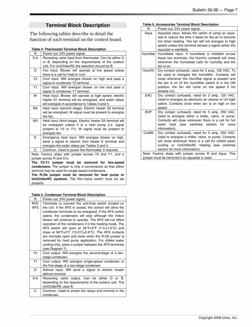
Terminal Block Description
The following tables describe in detail the function of each terminal on the control board. Table 4. Thermostat Terminal Block Description
R Power out. 24V power signal. O-b Reversing valve input from thermostat. Can be either O
or B, depending on the requirements of the outdoor unit. For UniChillerRC the selection should be B.
G Fan input. Blower will operate at low speed unless there is a call for heat or cool
Y2 Cool input. Will energize blower on high and pass a signal to condenser Y2 terminal.
Y1 Cool input. Will energize blower on low and pass a signal to condenser Y1 terminal.
W Heat input. Blower will operate at high speed, electric heater S1 terminal will be energized, and water relays will energize in accordance to Tables 3 and 4.
W2 Heat input (second stage). Electric heater S2 terminal will be energized. W signal must be present to energize the fan.
W3 Heat input (third stage). Electric heater S3 terminal will be energized unless it is a heat pump (i.e. signal present at Y2 or Y1). W signal must be present to energize fan.
E Emergency heat input. Will energize blower on high, send a signal to electric duct heater E terminal and energize the water relays per Tables 3 and 4.
C Common. Used to power the thermostat, if required. Note: Factory ships with jumper across Y2 and Y1, and a jumper across R and O-b. The Y2-Y1 jumper must be removed for two-speed condensers. The jumper is only a convenience so that either terminal may be used for single-speed condensers. The R-Ob jumper must be removed for heat pump or UniChillerRC systems. The Rev.Valve switch must be set properly.
Table 5. Condenser Terminal Block Description R Power out. 24V power signal.
AFS-AFS
Terminals to connect the anti-frost switch located on the coil. If the AFS is closed, the control will allow the condenser terminals to be energized. If the AFS switch opens, the condensers will stop although the indoor blower will continue to operate. The AFS will not affect operation of the condensers if in the heating mode. The AFS switch will open at 34°F±3°F (1°C±1.6°C) and close at 60°F±3°F (15.5°C±2.8°C). The AFS contacts are normally open and close when the R-Ob jumper is removed for heat pump application. For chilled water cooling only, place a jumper between the AFS terminals (see Diagram 7).
Y2 Cool output. Will energize the second-stage of a two-stage condenser.
Y1 Cool output. Will energize single-speed condenser or the first-stage of a two-stage condenser.
D Defrost input. Will send a signal to electric heater defrost terminal.
O-b Reversing valve output. Can be either O or B, depending on the requirements of the outdoor unit. The UniChillerRC uses B.
C Common. Used to power the relays and controls in the condenser.
Table 6. Accessories Terminal Block Description R Power out. 24V power signal.
Aqua Aquastat input. Allows the option of using an aqua-stat to reduce the time it takes for the air to become hot when heating. The fan will not energize to high speed unless this terminal senses a signal (when the aquastat is satisfied).
HumStat Humidistat input. If humidistat is installed across these two terminals, the HumVlv contacts will close whenever the humidistat calls for humidity and the fan is on.
HumVlv Dry contact (unfused), rated for 3 amp, 120 VAC. To be used to energize the humidifier. Contacts will close whenever the HumStat signal is present and the fan is on (If the humidifier switch is in the ON position, the fan will come on low speed if not already on).
EAC Dry contact (unfused), rated for 3 amp, 120 VAC. Used to energize an electronic air cleaner or UV-light option. Contacts close when fan is on high or low speed.
BVP Dry contact (unfused), rated for 5 amp, 250 VAC. Used to energize either a boiler, valve, or pump. Contacts will close whenever there is a call for hot water heat (see switches section for more information).
ColdW Dry contact (unfused), rated for 5 amp, 250 VAC. Used to energize a chiller, valve, or pump. Contacts will close whenever there is a call for chilled water cooling or UniChillerRC heating (see switches section for more information).
Note: Factory ships with jumper across R and Aqua. This jumper must be removed if an aquastat is used.
Bulletin 30-38 — Page 8
© Copyright 2008 Unico, Inc.
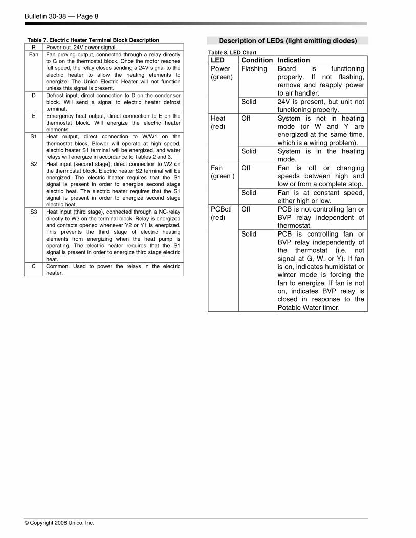
Table 7. Electric Heater Terminal Block Description R Power out. 24V power signal.
Fan Fan proving output, connected through a relay directly to G on the thermostat block. Once the motor reaches full speed, the relay closes sending a 24V signal to the electric heater to allow the heating elements to energize. The Unico Electric Heater will not function unless this signal is present.
D Defrost input, direct connection to D on the condenser block. Will send a signal to electric heater defrost terminal.
E Emergency heat output, direct connection to E on the thermostat block. Will energize the electric heater elements.
S1 Heat output, direct connection to W/W1 on the thermostat block. Blower will operate at high speed, electric heater S1 terminal will be energized, and water relays will energize in accordance to Tables 2 and 3.
S2 Heat input (second stage), direct connection to W2 on the thermostat block. Electric heater S2 terminal will be energized. The electric heater requires that the S1 signal is present in order to energize second stage electric heat. The electric heater requires that the S1 signal is present in order to energize second stage electric heat.
S3 Heat input (third stage), connected through a NC-relay directly to W3 on the terminal block. Relay is energized and contacts opened whenever Y2 or Y1 is energized. This prevents the third stage of electric heating elements from energizing when the heat pump is operating. The electric heater requires that the S1 signal is present in order to energize third stage electric heat.
C Common. Used to power the relays in the electric heater.
Description of LEDs (light emitting diodes)
Table 8. LED Chart
LED Condition Indication Power (green)
Flashing Board is functioning properly. If not flashing, remove and reapply power to air handler.
Solid 24V is present, but unit not functioning properly.
Heat (red)
Off System is not in heating mode (or W and Y are energized at the same time, which is a wiring problem).
Solid System is in the heating mode.
Fan (green )
Off Fan is off or changing speeds between high and low or from a complete stop.
Solid Fan is at constant speed, either high or low.
PCBctl (red)
Off PCB is not controlling fan or BVP relay independent of thermostat.
Solid PCB is controlling fan or BVP relay independently of the thermostat (i.e. not signal at G, W, or Y). If fan is on, indicates humidistat or winter mode is forcing the fan to energize. If fan is not on, indicates BVP relay is closed in response to the Potable Water timer.
Bulletin 30-38 — Page 9
Copyright 2008 Unico, Inc.
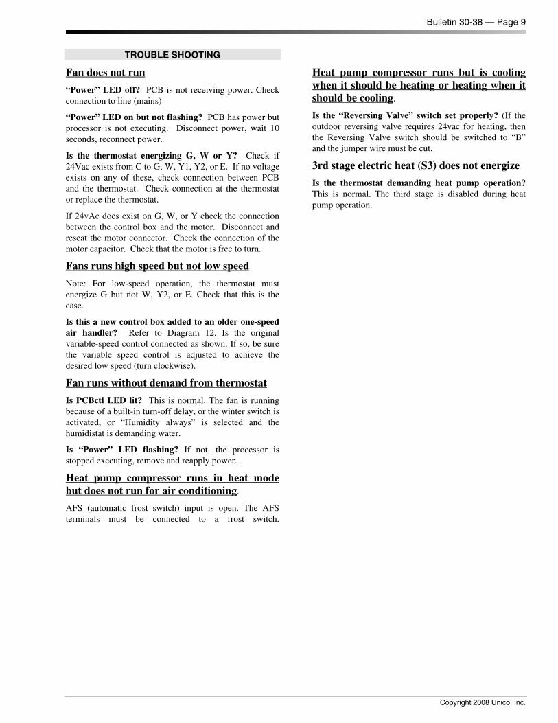
TROUBLE SHOOTING
Fan does not run
“Power” LED off? PCB is not receiving power. Check connection to line (mains)
“Power” LED on but not flashing? PCB has power but processor is not executing. Disconnect power, wait 10 seconds, reconnect power.
Is the thermostat energizing G, W or Y? Check if 24Vac exists from C to G, W, Y1, Y2, or E. If no voltage exists on any of these, check connection between PCB and the thermostat. Check connection at the thermostat or replace the thermostat.
If 24vAc does exist on G, W, or Y check the connection between the control box and the motor. Disconnect and reseat the motor connector. Check the connection of the motor capacitor. Check that the motor is free to turn.
Fans runs high speed but not low speed
Note: For low-speed operation, the thermostat must energize G but not W, Y2, or E. Check that this is the case.
Is this a new control box added to an older one-speed air handler? Refer to Diagram 12. Is the original variable-speed control connected as shown. If so, be sure the variable speed control is adjusted to achieve the desired low speed (turn clockwise).
Fan runs without demand from thermostat
Is PCBctl LED lit? This is normal. The fan is running because of a built-in turn-off delay, or the winter switch is activated, or “Humidity always” is selected and the humidistat is demanding water.
Is “Power” LED flashing? If not, the processor is stopped executing, remove and reapply power.
Heat pump compressor runs in heat mode but does not run for air conditioning.
AFS (automatic frost switch) input is open. The AFS terminals must be connected to a frost switch.
Heat pump compressor runs but is cooling when it should be heating or heating when it should be cooling.
Is the “Reversing Valve” switch set properly? (If the outdoor reversing valve requires 24vac for heating, then the Reversing Valve switch should be switched to “B” and the jumper wire must be cut.
3rd stage electric heat (S3) does not energize
Is the thermostat demanding heat pump operation? This is normal. The third stage is disabled during heat pump operation.
Bulletin 30-38 — Page 10
© Copyright 2008 Unico, Inc.
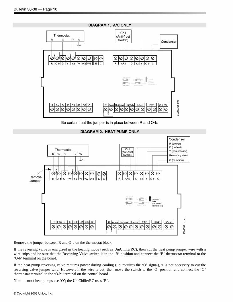
DIAGRAM 1. A/C ONLY
Be certain that the jumper is in place between R and O-b.
DIAGRAM 2. HEAT PUMP ONLY
Remove the jumper between R and O-b on the thermostat block.
If the reversing valve is energized in the heating mode (such as UniChillerRC), then cut the heat pump jumper wire with a wire snips and be sure that the Reversing Valve switch is in the ‘B’ position and connect the ‘B’ thermostat terminal to the ‘O-b’ terminal on the board.
If the heat pump reversing valve requires power during cooling (i.e. requires the ‘O’ signal), it is not necessary to cut the reversing valve jumper wire. However, if the wire is cut, then move the switch to the ‘O’ position and connect the ‘O’ thermostat terminal to the ‘O-b’ terminal on the control board.
Note — most heat pumps use ‘O’; the UniChillerRC uses ‘B’.
Bulletin 30-38 — Page 11
© Copyright 2008 Unico, Inc.
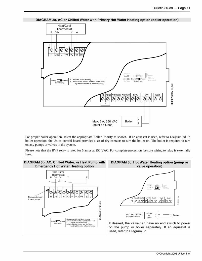
DIAGRAM 3a. AC or Chilled Water with Primary Hot Water Heating option (boiler operation)
For proper boiler operation, select the appropriate Boiler Priority as shown. If an aquastat is used, refer to Diagram 3d. In boiler operation, the Unico control board provides a set of dry contacts to turn the boiler on. The boiler is required to turn on any pumps or valves in the system.
Please note that the BVP relay is rated for 5 amps at 250 VAC. For complete protection, be sure wiring to relay is externally fused.
DIAGRAM 3b. AC, Chilled Water, or Heat Pump with Emergency Hot Water Heating option
DIAGRAM 3c. Hot Water Heating option (pump or valve operation)
ColdBVPEACHumvlvAquaR Humstat
Pumpor
Valve
XX
+-
Power
Emerg PrimaryBoiler PriorityRevValve
B O
Mtr Speed1 2
RampOn Off Jumper
Wire,Cut if Rev.Valve usesB
Max. 5 A, 250 VAC(must be fused)
If desired, the valve can have an end switch to power on the pump or boiler separately. If an aquastat is used, refer to Diagram 3d.
Bulletin 30-38 — Page 12
© Copyright 2008 Unico, Inc.
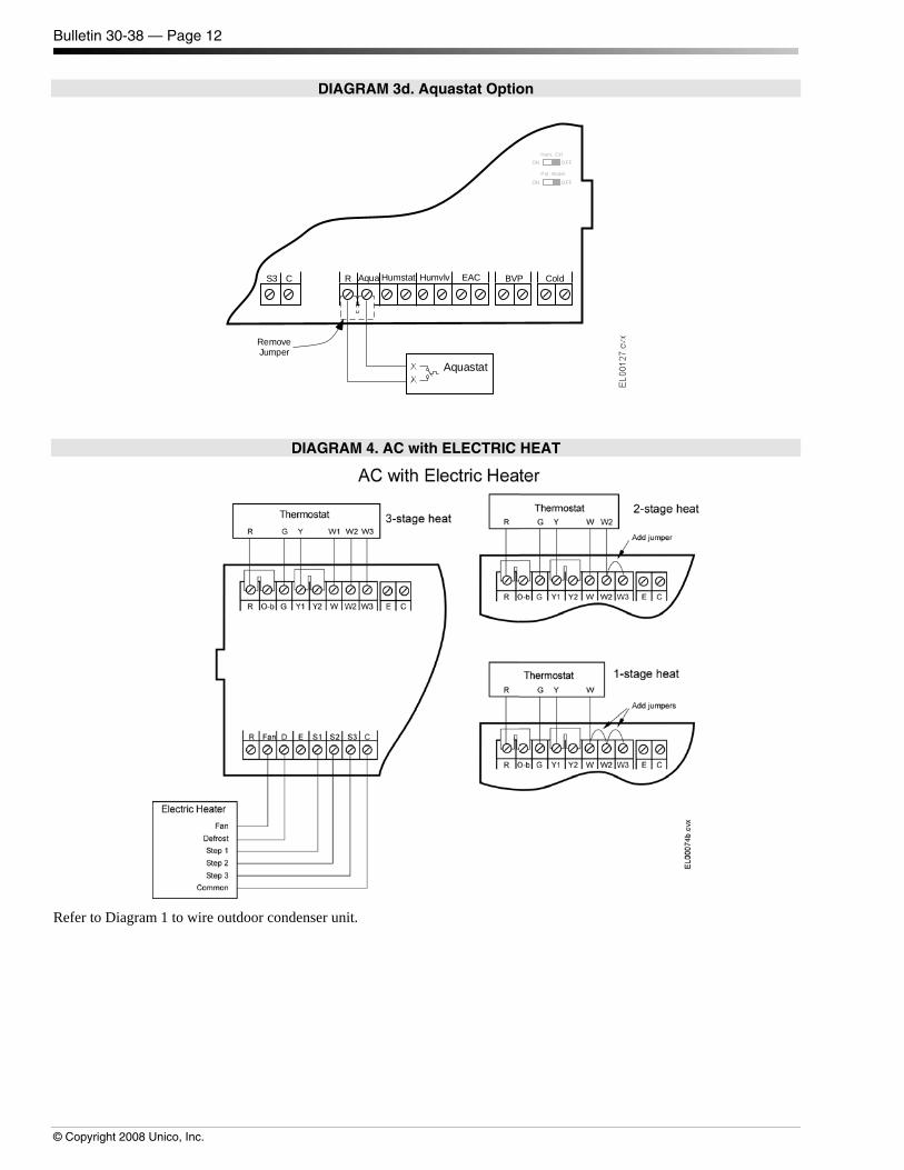
DIAGRAM 3d. Aquastat Option
Pot. WaterON OFF
Hum. Ctr lON OFF
ColdBVPEACHumvlvAquaRCS3 Humstat
Aquastat
RemoveJumper
DIAGRAM 4. AC with ELECTRIC HEAT
Refer to Diagram 1 to wire outdoor condenser unit.

Bulletin 30-38 — Page 13
© Copyright 2008 Unico, Inc.
DIAGRAM 5. Heat Pump with Emergency Heat
Refer to Diagram 2 to wire outdoor heat pump and for instructions for setting the reversing valve O-b switch.
For 2 or 3-stage heating, if hot water coil is used for emergency heat, then do not connect the thermostat E to W and refer to Diagram 3b.
DIAGRAM 6. Emergency-Only Electric Heater
Bulletin 30-38 — Page 14
© Copyright 2008 Unico, Inc.
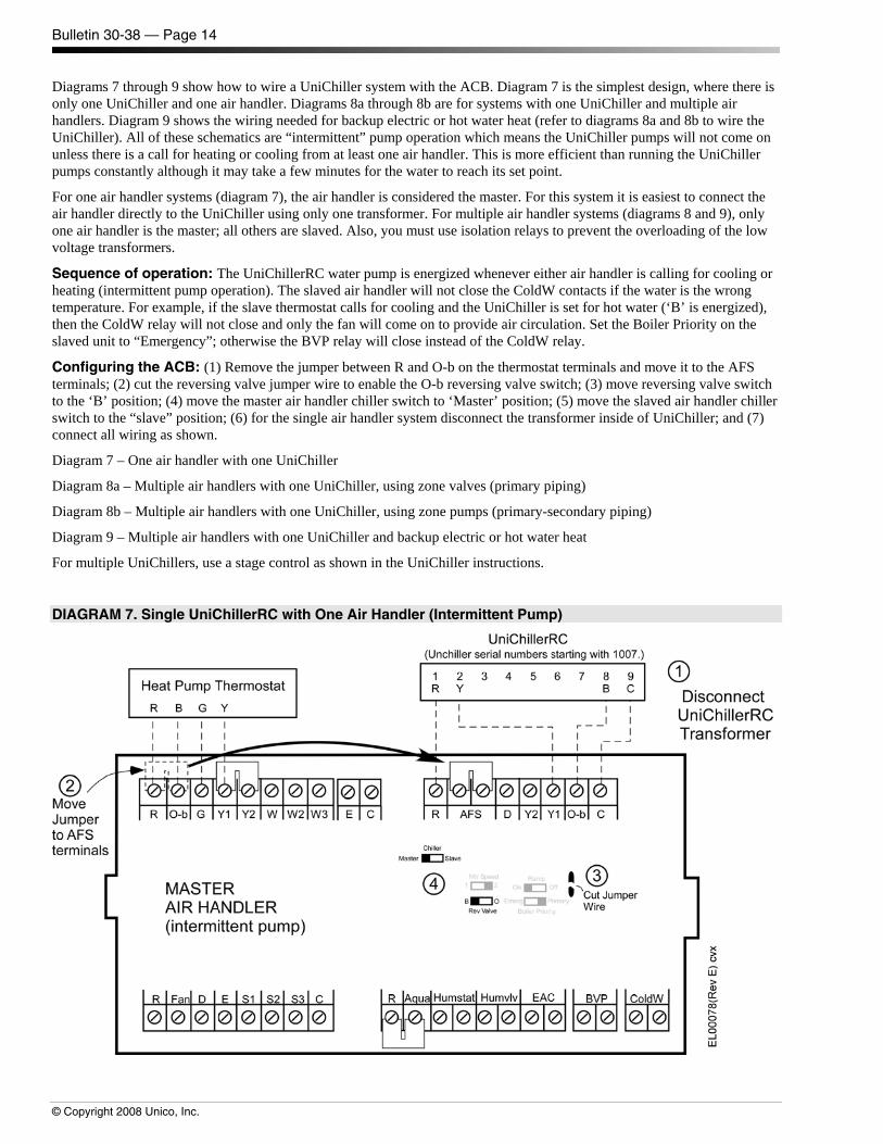
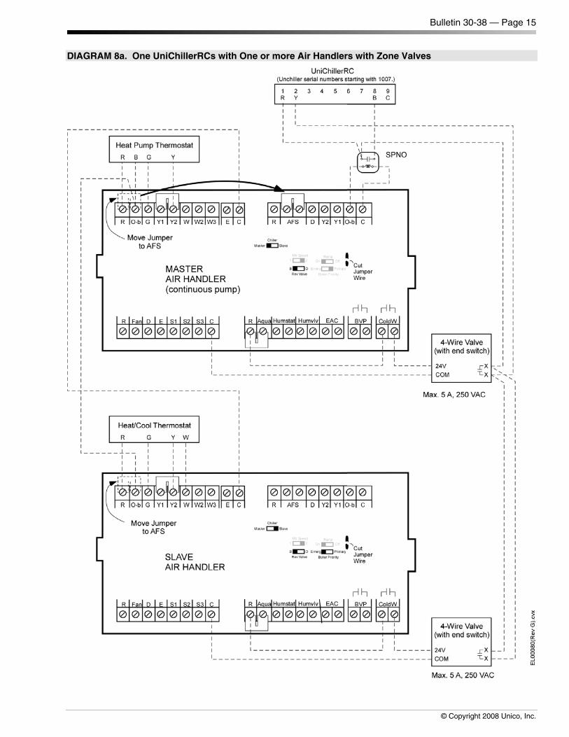
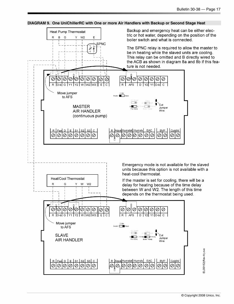
Diagrams 7 through 9 show how to wire a UniChiller system with the ACB. Diagram 7 is the simplest design, where there is only one UniChiller and one air handler. Diagrams 8a through 8b are for systems with one UniChiller and multiple air handlers. Diagram 9 shows the wiring needed for backup electric or hot water heat (refer to diagrams 8a and 8b to wire the UniChiller). All of these schematics are “intermittent” pump operation which means the UniChiller pumps will not come on unless there is a call for heating or cooling from at least one air handler. This is more efficient than running the UniChiller pumps constantly although it may take a few minutes for the water to reach its set point.
For one air handler systems (diagram 7), the air handler is considered the master. For this system it is easiest to connect the air handler directly to the UniChiller using only one transformer. For multiple air handler systems (diagrams 8 and 9), only one air handler is the master; all others are slaved. Also, you must use isolation relays to prevent the overloading of the low voltage transformers.
Sequence of operation: The UniChillerRC water pump is energized whenever either air handler is calling for cooling or heating (intermittent pump operation). The slaved air handler will not close the ColdW contacts if the water is the wrong temperature. For example, if the slave thermostat calls for cooling and the UniChiller is set for hot water (‘B’ is energized), then the ColdW relay will not close and only the fan will come on to provide air circulation. Set the Boiler Priority on the slaved unit to “Emergency”; otherwise the BVP relay will close instead of the ColdW relay.
Configuring the ACB: (1) Remove the jumper between R and O-b on the thermostat terminals and move it to the AFS terminals; (2) cut the reversing valve jumper wire to enable the O-b reversing valve switch; (3) move reversing valve switch to the ‘B’ position; (4) move the master air handler chiller switch to ‘Master’ position; (5) move the slaved air handler chiller switch to the “slave” position; (6) for the single air handler system disconnect the transformer inside of UniChiller; and (7) connect all wiring as shown.
Diagram 7 – One air handler with one UniChiller
Diagram 8a – Multiple air handlers with one UniChiller, using zone valves (primary piping)
Diagram 8b – Multiple air handlers with one UniChiller, using zone pumps (primary-secondary piping)
Diagram 9 – Multiple air handlers with one UniChiller and backup electric or hot water heat
For multiple UniChillers, use a stage control as shown in the UniChiller instructions.
DIAGRAM 7. Single UniChillerRC with One Air Handler (Intermittent Pump)
Bulletin 30-38 — Page 15
© Copyright 2008 Unico, Inc.
DIAGRAM 8a. One UniChillerRCs with One or more Air Handlers with Zone Valves

Bulletin 30-38 — Page 16
© Copyright 2008 Unico, Inc.
DIAGRAM 8b. One UniChillerRC with One or more Air Handlers with Zone Pumps
Bulletin 30-38 — Page 17
© Copyright 2008 Unico, Inc.
DIAGRAM 9. One UniChillerRC with One or more Air Handlers with Backup or Second Stage Heat
Bulletin 30-38 — Page 18
© Copyright 2008 Unico, Inc.
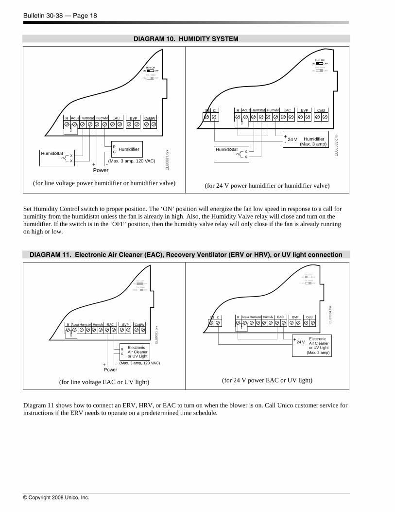
DIAGRAM 10. HUMIDITY SYSTEM
ColdWBVPEACHumvlvAquaR Humstat
+ -Power
Hum. CtrlON OFF
Pot. WaterON OFF
HumidiStat XX
HumidifierRC
(Max. 3 amp, 120 VAC)
(for line voltage power humidifier or humidifier valve)
Hum. CtrlON OFF
Pot. WaterON OFF
ColdBVPEACHumvlvAquaRCS3 Humstat
HumidiStat XX
Humidifier+- 24 V
(Max. 3 amp)
(for 24 V power humidifier or humidifier valve)
Set Humidity Control switch to proper position. The ‘ON’ position will energize the fan low speed in response to a call for humidity from the humidistat unless the fan is already in high. Also, the Humidity Valve relay will close and turn on the humidifier. If the switch is in the ‘OFF’ position, then the humidity valve relay will only close if the fan is already running on high or low.
DIAGRAM 11. Electronic Air Cleaner (EAC), Recovery Ventilator (ERV or HRV), or UV light connection
ColdWBVPEACHumvlvAquaR Humstat
+ -Power
Hum. CtrlON OFF
Pot. WaterON OFF
ElectronicAir Cleaneror UV Light
RC
(Max. 3 amp, 120 VAC)
(for line voltage EAC or UV light)
Hum. CtrlON OFF
Pot. WaterON OFF
ColdBVPEACHumvlvAquaRCS3 Humstat
+- 24 V
(Max. 3 amp)
ElectronicAir Cleaneror UV Light
(for 24 V power EAC or UV light)
Diagram 11 shows how to connect an ERV, HRV, or EAC to turn on when the blower is on. Call Unico customer service for instructions if the ERV needs to operate on a predetermined time schedule.
Bulletin 30-38 — Page 19
© Copyright 2008 Unico, Inc.
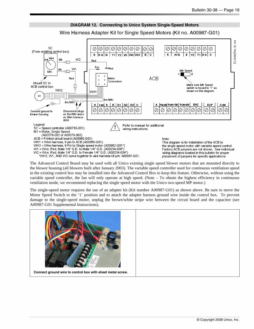
DIAGRAM 12. Connecting to Unico System Single-Speed Motors
The Advanced Control Board may be used with all Unico existing single speed blower motors that are mounted directly to the blower housing (all blowers built after January 2003). The variable speed controller used for continuous ventilation speed in the existing control box may be installed into the Advanced Control Box to keep this feature. Otherwise, without using the variable speed controller, the fan will only operate at high speed. (Note – To obtain the highest efficiency in continuous ventilation mode, we recommend replacing the single speed motor with the Unico two-speed MP motor.)
The single-speed motor requires the use of an adapter kit (Kit number A00987-G01) as shown above. Be sure to move the Motor Speed Switch to the ‘1’ position and to attach the adapter harness ground wire inside the control box. To prevent damage to the single-speed motor, unplug the brown/white stripe wire between the circuit board and the capacitor (see A00987-G01 Supplemental Instructions).
Connect ground wire to control box with sheet metal screw.
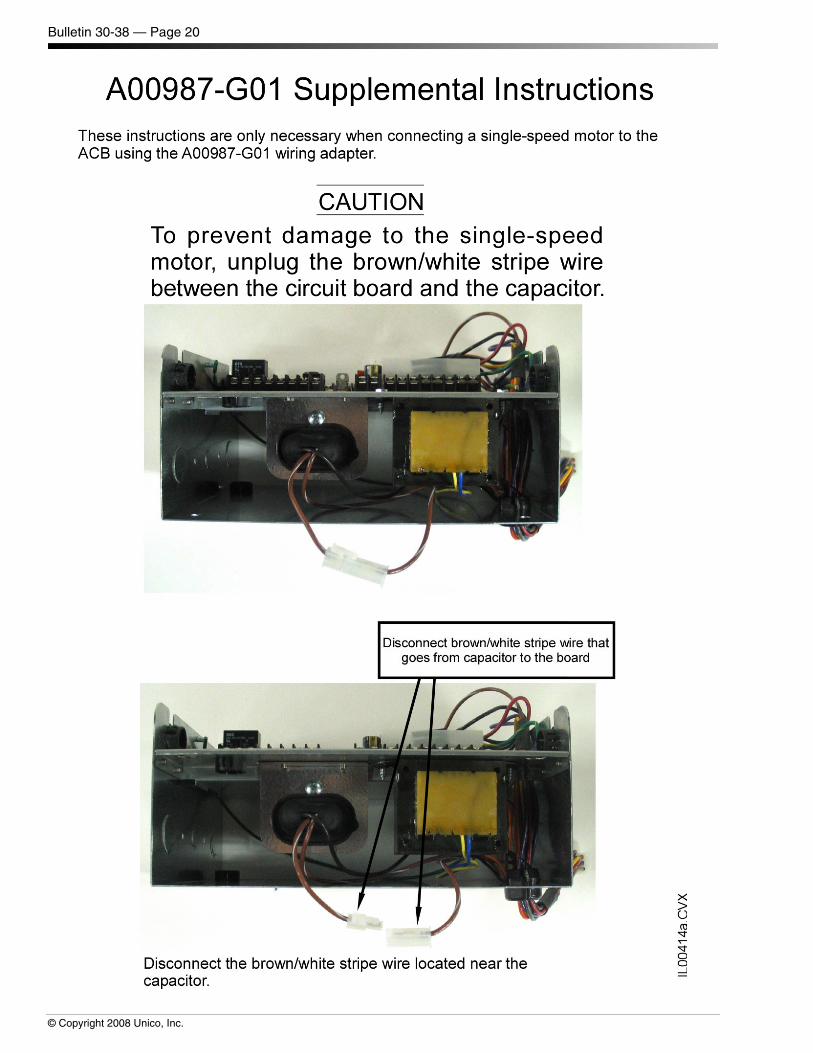
Bulletin 30-38 — Page 20
© Copyright 2008 Unico, Inc.
Bulletin 30-38 — Page 21
© Copyright 2008 Unico, Inc.
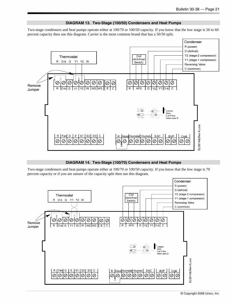
DIAGRAM 13. Two-Stage (100/50) Condensers and Heat Pumps
Two-stage condensers and heat pumps operate either at 100/70 or 100/50 capacity. If you know that the low stage is 50 to 60 percent capacity then use this diagram. Carrier is the most common brand that has a 50/50 split.
DIAGRAM 14. Two-Stage (100/70) Condensers and Heat Pumps
Two-stage condensers and heat pumps operate either at 100/70 or 100/50 capacity. If you know that the low stage is 70 percent capacity or if you are unsure of the capacity split then use this diagram.
Bulletin 30-38 — Page 22
© Copyright 2008 Unico, Inc.
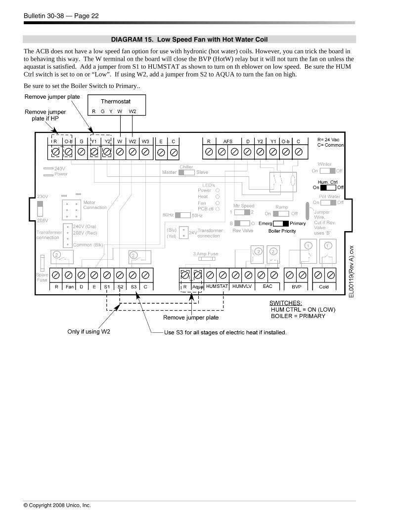
DIAGRAM 15. Low Speed Fan with Hot Water Coil
The ACB does not have a low speed fan option for use with hydronic (hot water) coils. However, you can trick the board in to behaving this way. The W terminal on the board will close the BVP (HotW) relay but it will not turn the fan on unless the aquastat is satisfied. Add a jumper from S1 to HUMSTAT as shown to turn on th eblower on low speed. Be sure the HUM Ctrl switch is set to on or “Low”. If using W2, add a jumper from S2 to AQUA to turn the fan on high.
Be sure to set the Boiler Switch to Primary..
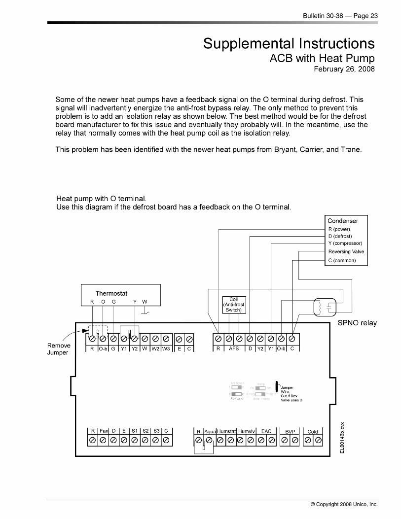
Bulletin 30-38 — Page 23
© Copyright 2008 Unico, Inc.