installation instructions - hvac parts...
TRANSCRIPT

13 SEER
INSTALLATION INSTRUCTIONS
Single Package Heat Pump - Single Stage, R-410A
Q5RD / PPH2RD SERIES
DO NOT DESTROY. PLEASE READ CAREFULLY AND KEEP IN A SAFE PLACE FOR FUTURE REFERENCE.
IMPORTANT
ATTENTION INSTALLERS:It is your responsibility to know this product better than your customer. This includes being able to install the product according to strict safety guidelines and instructing the customer on how to operate and maintain the equipment for the life of the product. Safety should always be the deciding factor when installing this product and using common sense plays an important role as well. Pay attention to all safety warnings and any other special notes highlighted in the manual. Improper installation of the furnace or failure to follow safety warnings could result in serious injury, death, or property damage.
These instructions are primarily intended to assist qualified individuals experienced in the proper installation of this appliance. Some local codes require licensed installation/service personnel for this type of equipment. Please read all instructions carefully before starting the installation. Return these instructions to the customer’s package for future reference.

2
Important Safety Information ....................................3
Requirements & Codes ..............................................4
General Information ...................................................4Before You Install this Unit .........................................4Locating the Heat pump ...........................................4Minimum Clearances ................................................5
Service Access Clearance ....................................5Clearances to Combustibles .................................5
Air Duct System ........................................................5Unconditioned Spaces ...........................................5
Heat Pump Installation ...............................................5Unpacking the Unit ...................................................5Installing Return & Supply Air Collars .......................5
Supply Duct ...........................................................6Return Duct ...........................................................6
Connecting Return & Supply AirFlexible Ducts ............................................................6Locating & Installing the Return AirAssembly ...................................................................6Locating & Installing the SupplyDampers ....................................................................7Condensate Drainage ...............................................7
Electrical Connections ...............................................7Pre - Electrical Checklist ...........................................7Line Voltage ...............................................................7Overcurrent Protection ..............................................8Grounding..................................................................8Thermostat Connections ...........................................8Defrost Cycle Control ................................................8Defrost Control Board................................................9
Operational Information..........................................9Normal Mode .........................................................9Speed Up Mode (Testing Procedure) .....................9
Electric Heat Package ...............................................9Blower Speed .........................................................10
Startup & Adjustments ............................................11Pre - Start Checklist ................................................11Start - Up Procedure ...............................................11
Air Circulation .......................................................11System Heating ....................................................11System Cooling ....................................................11Short Cycle Protection .........................................11Emergency Heat ..................................................11
Anti Short Cycle Timer Test .....................................11Heating Mode .......................................................11Cooling Mode .......................................................11
Adjustment of Refrigerant Charge ...........................11Charging the Unit in AC Mode with OutdoorTemperatures above 65° F ......................................12Charging the Unit in Heat Mode ..............................12
Unit Maintenance ...................................................... 12
Component Functions ............................................. 12
Figures & Tables ....................................................... 13Figure 8 - Physical Data & Dimensions ................ 13
Charging Tables - Cooling Mode ............................. 14Table 3 - 2 Ton Models (024K Series) .................. 14Table 4 - 2.5 Ton Models (030K Series) ............... 14Table 5 - 3 Ton Models (036K / 36KA Series) ...... 15Table 6 - 3.5 Ton Models (042K Series) ............... 15Table 7 - 4 Ton Models (048K Series) .................. 16Figure 9 - 4 Ton Models (048KA Series) .............. 16Table 8 - 5 Ton Models (060K Series) .................. 16
Charging Tables - Heating Mode ............................. 17Table 9 - 2 Ton Models (024K Series) .................. 17Table 10 - 2.5 Ton Models (030K Series) ............. 17Table 11 - 3 Ton Models (036K / KA Series) ........ 18Table 12 - 3.5 Ton Models (042K Series) ............. 19Table 13 - 4 Ton Models (048K Series) ................ 19Table 14 - 4 Ton Models (048KA Series) .............. 20Table 15 - 5 Ton Models (060K Series) ................ 20
Electrical Diagrams ................................................. 21Figure 10 - 2, 2.5, 3, & 4 Ton Models ................... 21Figure 11 - 3.5 & 5 Ton Models ............................ 22Figure 12 - Typical T-stat Connections ................. 23
Installation / Performance Checklist ....................... 24
TAbLE OF CONTENTS
3
IMPORTANT SAFETY INFORMATIONPlease read all instructions before servicing this equipment. Pay attention to all safety warnings and any other special notes highlighted in the manual. Safety markings are used frequently throughout this manual to designate a degree or level of seriousness and should not be ignored. WARNING indicates a potentially hazardous situation that if not avoided, could result in personal injury or death. CAUTION indicates a potentially hazardous situation that if not avoided, may result in minor or moderate injury or property damage.
WARNING:ELECTRICAL SHOCK, FIRE OR EXPLOSION HAZARD
Failure to follow safety warnings exactly could result in serious injury or property damage.
Improper servicing could result in dangerous operation, serious injury, death or property damage.
• Beforeservicing,disconnectallelectricalpowerto the indoor blower.
• Whenservicingcontrols,labelallwirespriorto disconnecting. Reconnect wires correctly.
• Verifyproperoperationafterservicing.
WARNING:These units are fully charged with R-410A refrigerant and ready for installation. When a system is installed according to these instructions, no refrigerant charging is required. If repairs make it necessary for evacuation and charging, it should only be attempted by qualified, trained personnel thoroughly familiar with this equipment. Some local codes require licensed installation service personnel to service this type of equipment. Under no circumstances should the homeowner attempt to install and/or service this equipment. Failure to comply with this warning could result in equipment damage, personal injury, or death.
WARNING:Do not place combustible material on or against the unit cabinet. Do not place combustible materials, including gasoline and any other flammable vapors and liquids, in the vicinity of the unit.
WARNING:PROPOSITION 65 WARNING: This product contains fiberglass wool, a product known to the state of California to cause cancer. Disturbing the insulation of this product during installation, maintenance, or repair will expose you to fiberglass wool.
• Breathingthismaterialmaycauserespiratoryirritations or may cause lung cancer.
• Fiberglass wool may also cause eyeirritation, skin sensitization, or other allergic responses in susceptible individuals.
• Always wear goggles, disposable gloves,long sleeved shirt, and appropriate breathing protection when working near this insulation. If contact with skin occurs, wash immediately with soap and water. In case of contact with eyes, flush immediately with water for at least 15 minutes. Contact a physician if needed.
WARNING:The information listed below and on the next page must be followed during the installation, service, and operation of this unit. Unqualified individuals should not attempt to interpret these instructions or install this equipment. Failure to follow safety recommendations could result in possible damage to the equipment, serious personal injury or death.
• Before beginning the installation, verify that the unitmodel is correct for the job. The unit model number is printed on the data label.
• Thisequipmentcontainsliquidandgaseousrefrigerantunder high pressure. Installation or servicing should only be performed by qualified trained personnel thoroughly familiar with this type equipment.
• Installationofequipmentmayrequirebrazingoperations.Installer must comply with safety codes and wear appropriate safety equipment (safety glasses, work gloves, fire extinguisher, etc.) when performing brazing operations.
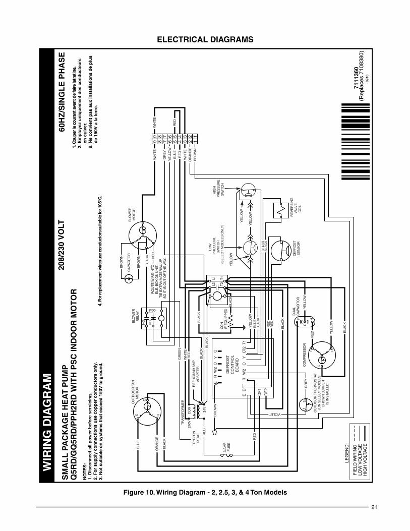
• Theinstallershouldbecomefamiliarwiththeunitswiringdiagram before making any electrical connections to the unit. See the unit wiring label or Figures 10 & 11 (pages 21 & 22).
• Follow all precautions in the literature, on tags, andon labels provided with the equipment. Read and

4
GENERAL INFORMATIONSingle packaged heat pumps are ready for easy and immediate installation and can be readily connected into the high static duct system of a home. This unit is completely assembled, wired, and run tested at the factory. This heat pump is designed for outdoor installation only. The only connections needed for installation are the supply and return ducts, the line voltage, and thermostat wiring. Use of components other than those specified may invalidate AHRI Certification, Code Agency Listing, and limited warranty on the air conditioner.
before You Install this Unit√ The cooling load of the area to be conditioned must be
calculated and a system of the proper capacity selected. It is recommended that the area to be conditioned be completely insulated and vapor sealed.
√ Check the electrical supply and verify the power supply is adequate for unit operation. If there is any question concerning the power supply, contact the local power company.
√ All units are securely packed at the time of shipment and upon arrival should be carefully inspected for damage prior to installing the equipment at the job site. Verify coil fins are straight. If necessary, comb fins to remove flattened or bent fins. Claims for damage should be filed immediately with the carrier.
√ Please consult your dealer for maintenance information and availability of maintenance contracts. Please read all instructions before installing the unit.
Locating the Heat Pump• Surveythejobsitetodeterminethebestlocationfor
mounting the outdoor unit. Select a solid, level position, preferably on a concrete slab, slightly above the grade level, and parallel to the home. If possible, select a site for the unit that is as close as possible to the proposed return grille location. DO NOT PLACE UNIT UNDER THE HOME.
• The unit should be located with consideration ofminimizing the length of the supply and return ducts with no sharp radius bends. If practical, place the heat pump and its ducts in an area where they will be shaded from the afternoon sun, when the heat load is greatest.
• Consideration should also be given to availability ofelectric power, service access, noise, and shade.
• Overhead obstructions, poorly ventilated areas, andareas subject to accumulation of debris should be avoided. The hot condenser air must be discharged up and away from the home, and if possible, in a direction with the prevailing wind. Do not place the unit in a confined space. See Figure 8 (page 13) for unit dimensions.
• Sufficientclearanceforunobstructedairflowthroughtheoutdoor coil must be maintained in order to achieve rated performance. For minimum clearances to obstructions, see Figure 1.
REQUIREMENTS & CODES• Allelectricalwiringmustbecompletedinaccordance
with local, state & national codes and regulations and with the National Electric Code (ANSI/NFPA 70) or in Canada the Canadian Electric Code Part 1 CSA C.22.1.
• The installer must comply with all local codes andregulations which govern the installation of this type of equipment. Local codes and regulations take precedence over any recommendations contained in these instructions. Consult local building codes and the National Electrical Code (ANSI CI) for special installation requirements.
• Air Ducts must be installed in accordance with thestandards of the National Fire Protection Association “Standards for Installation of Air Conditioning and Ventilation Systems” (NFPA 90A), “Standard for Installation of Residence Type Warm Air Heating and Air Conditioning Systems” (NFPA 90B), these instructions, and all applicable local codes.
• ConsultTable2(page10),andtheratingplatefortheproper circulating air flow and temperature rise. It is important that the duct system be designed to provide the correct flow rates and external pressure rise. An improperly designed duct system can result in nuisance shutdowns, and comfort or noise issues.
• Thisunitisdesignedforoutdoorinstallationsonlyandshould be positioned as described in Locating the Heat Pump.
thoroughly understand the instructions provided with the equipment prior to performing the installation and operational checkout of the equipment.
• Usecautionwhenhandlingthisapplianceorremovingcomponents. Personal injury can occur from sharp metal edges present in all sheet metal constructed equipment.
Figure 1. Minimum Unit Clearances
12"
12"24"
TOP
OF
UN
ITTO
BE
UN
OB
ST
RU
CT
ED
0"
5
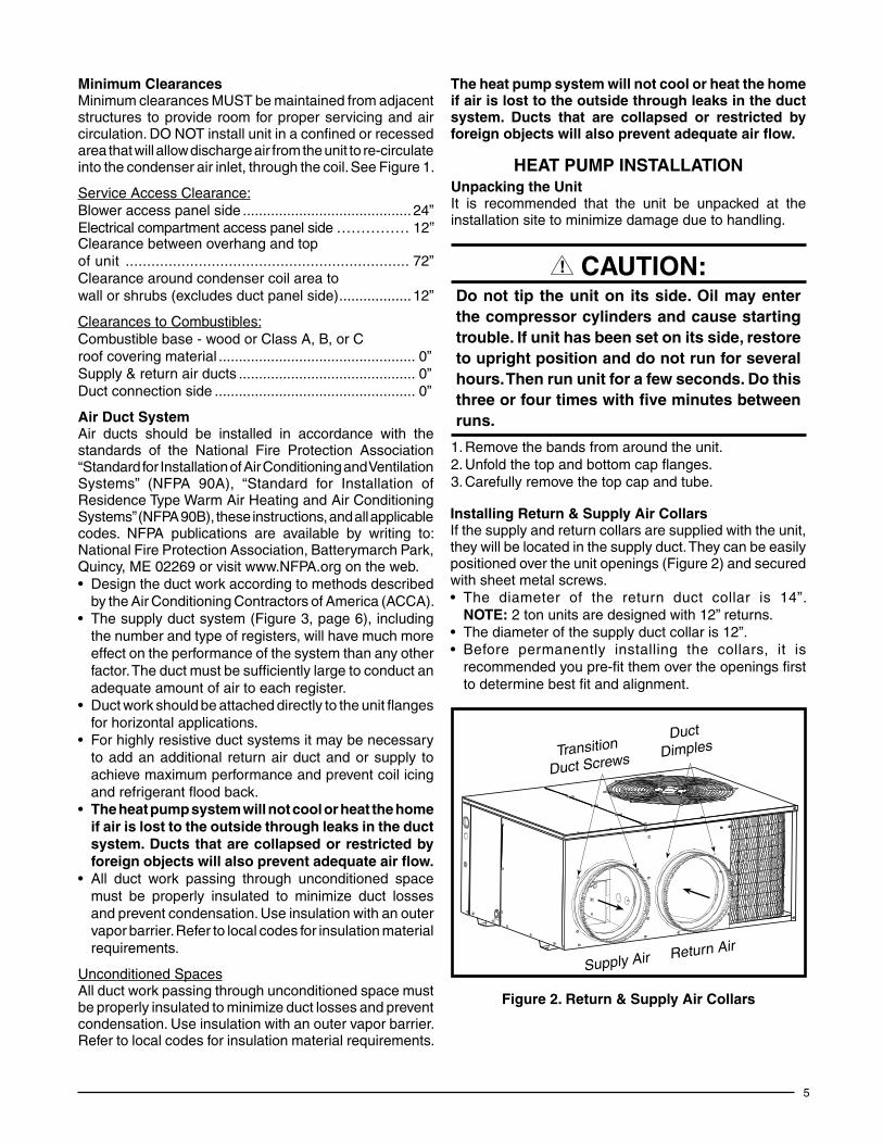
HEAT PUMP INSTALLATIONUnpacking the UnitIt is recommended that the unit be unpacked at the installation site to minimize damage due to handling.
CAUTION:Do not tip the unit on its side. Oil may enter the compressor cylinders and cause starting trouble. If unit has been set on its side, restore to upright position and do not run for several hours. Then run unit for a few seconds. Do this three or four times with five minutes between runs.
1. Remove the bands from around the unit.2. Unfold the top and bottom cap flanges.3. Carefully remove the top cap and tube.
Minimum ClearancesMinimum clearances MUST be maintained from adjacent structures to provide room for proper servicing and air circulation. DO NOT install unit in a confined or recessed area that will allow discharge air from the unit to re-circulate into the condenser air inlet, through the coil. See Figure 1.
Service Access Clearance:Blower access panel side .......................................... 24”Electrical compartment access panel side ............... 12”Clearance between overhang and topof unit .................................................................. 72”Clearance around condenser coil area towall or shrubs (excludes duct panel side) .................. 12”
Clearances to Combustibles:Combustible base - wood or Class A, B, or Croof covering material ................................................. 0”Supply & return air ducts ............................................ 0”Duct connection side .................................................. 0”
Air Duct SystemAir ducts should be installed in accordance with the standards of the National Fire Protection Association “Standard for Installation of Air Conditioning and Ventilation Systems” (NFPA 90A), “Standard for Installation of Residence Type Warm Air Heating and Air Conditioning Systems” (NFPA 90B), these instructions, and all applicable codes. NFPA publications are available by writing to: National Fire Protection Association, Batterymarch Park, Quincy, ME 02269 or visit www.NFPA.org on the web.• Designtheductworkaccordingtomethodsdescribed
by the Air Conditioning Contractors of America (ACCA).• Thesupplyductsystem(Figure3,page6),including
the number and type of registers, will have much more effect on the performance of the system than any other factor. The duct must be sufficiently large to conduct an adequate amount of air to each register.
• Ductworkshouldbeattacheddirectlytotheunitflangesfor horizontal applications.
• Forhighlyresistiveductsystemsitmaybenecessaryto add an additional return air duct and or supply to achieve maximum performance and prevent coil icing and refrigerant flood back.
• The heat pump system will not cool or heat the home if air is lost to the outside through leaks in the duct system. Ducts that are collapsed or restricted by foreign objects will also prevent adequate air flow.
• All duct work passing through unconditioned space must be properly insulated to minimize duct losses and prevent condensation. Use insulation with an outer vapor barrier. Refer to local codes for insulation material requirements.
Unconditioned SpacesAll duct work passing through unconditioned space must be properly insulated to minimize duct losses and prevent condensation. Use insulation with an outer vapor barrier. Refer to local codes for insulation material requirements.
Installing Return & Supply Air CollarsIf the supply and return collars are supplied with the unit, they will be located in the supply duct. They can be easily positioned over the unit openings (Figure 2) and secured with sheet metal screws.• The diameter of the return duct collar is 14”.
NOTE: 2 ton units are designed with 12” returns.• Thediameterofthesupplyductcollaris12”.• Before permanently installing the collars, it is
recommended you pre-fit them over the openings first to determine best fit and alignment.
Figure 2. Return & Supply Air Collars
Transition
Duct Screws
Supply Air Return Air
Duct
Dimples
The heat pump system will not cool or heat the home if air is lost to the outside through leaks in the duct system. Ducts that are collapsed or restricted by foreign objects will also prevent adequate air flow.

6
Figure 3. Typical Duct Applications
MULTIPLE DUCT APPLICATIONSINGLE DUCT APPLICATION
Supply Duct1. Assemble the collar by overlapping the two ends.
NOTE: One end of the collar is slotted and the opposite end has two small holes. Position the end with small screw holes underneath the slotted end.
2. Fasten the collar ends with two self drilling sheet metal screws.
3. Position the collar over the opening and align the 4 holes in the collar with the 4 holes (or dimples depending on model) in the rear panel.
4. Using self-drilling screws (10-16x.5), secure the collar to the rear panel.
Return Duct1. Assemble the collar by overlapping the two ends.
NOTE: One end of the collar is slotted and the opposite end has two small holes. Position the end with small screw holes underneath the slotted end.
2. Fasten the collar ends with two self drilling sheet metal screws.
3. Position the collar over the opening. Align the four holes in the collar with the four dimples or holes (depending on unit model) in the panel.
4. Secure the collar to the rear panel using self tapping screws (10-16x.5).
Connecting Return & Supply Air Flexible Ducts• Flexibleductsmaybecut totherequiredlengthand
spliced with sheet metal sleeves and clamps. Keep all ducts as short and straight as possible. Avoid sharp bends. Please follow all instructions packed with duct.
• Flexible ducts can be secured to the correspondingcollars with the provided clamps. After the inner duct is connected to the collar, pull the insulation and plastic sleeve over the connection and clamp. NOTE: To prevent a loss in cooling capacity, make sure all connections are tight.
• Homes with multiple supply ducts (or specialapplications), a Y fitting is available for dividing the supply air to different areas of the home for more efficient cooling. NOTE: For maximum performance, insulate the Y fitting.
Locating & Installing the Return Air AssemblyTo simplify installation, locate and install the return air assembly first. If desired, the return opening can be located inside a closet with louvered doors that has an open area equal to or greater than a 12” x 20” grille. The return air grille can be placed in the wall of a closet and the ducted into the filter box through a boxed-in area at the closet floor level. Make sure the filter is readily accessible.
NOTE: The return air box with grille and filter (Figure 4, page 7) should not be located in heavy traffic areas like hallways or center of rooms. A good spot is in a corner or under a table, if a minimum two inch clearance is available.
1. Start the installation from under the home by cutting a small hole in the sub-floor. Determine how the floor joist location will affect cutting the opening needed for the return air box. NOTE: Floor joists are generally located on 16” centers, leaving 14-3/8” between joists.
2. After measuring the return air box (approximately 12-1/4” x 20-1/4”), cut the hole through the floor so that the box will fit between the floor joists. Care should be taken when cutting through carpeting to avoid snags. NOTE: In most installations it will be necessary to cut a similar hole in the fiberboard directly under the hole in the floor. However, if the floor is more than ten inches deep, it will only be necessary to cut a hole for the collar on the return air box or for the insulated duct.
3. Set the box into the opening and fasten with screws or nails.
4. Install the filter and return air grille in place.

7
Figure 5. Supply Damper
AUTOMATIC DAMPER IS CLOSEDWHEN HEAT PUMP IS OFF
Figure 4. Return Air box
Locating & Installing the Supply Damper(s)When locating the supply damper(s), carefully check floor joists and frame members that could interfere with the installation of the damper or flexible duct. Ideally, the damper (Figure 5) should be located in the bottom of the main duct, forward of center of the home, at least three feet from the nearest register. The round supply opening in the slanted side of the damper should face the side of the home where the heat pump is located.
1. Locate the center of the heat duct by cutting a small hole in the fiberboard below the duct at the desired location.
2. Cut a hole approximately 3/4” larger than the damper opening in the fiberboard.
3. Cut a 9-1/8” x 13-1/8” hole in the duct and bend over all tabs flat on the inside of the heat duct.
4. Insert the damper into the duct and bend over all tabs flat on the inside of the heat duct.
5. Seal the opening between the fiberboard and damper or flexible duct.
Figure 6. Drain Trap
Elbow
P-Trap
1. Thread the elbow provided with the unit into the drain connection until hand tight.
2. Connect the condensate tubing onto the fitting, forming a trap (Figure 6) near the drain connection.
3. Route the condensate tube from the trap to a suitable drain. NOTE: For proper drainage, make sure the trap is level to the ground and tubing outlet is below trap level.
Condensate DrainageA 3/4” condensate fitting extends out of the side of the unit as shown in Figure 6. The drain trap, shipped in the electrical compartment, must be installed to prevent water from collecting inside the unit.
ELECTRICAL CONNECTIONS
WARNING:To avoid electric shock, personal injury, or death, turn off the electric power at the disconnect or the main service panel before making any electrical connections.
• Electrical connections must be in compliance withall applicable local codes and ordinances, and with the current revision of the National Electric Code (ANSI/NFPA 70).
• ForCanadian installations theelectrical connectionsand grounding shall comply with the current Canadian Electrical Code (CSA C22.1 and/or local codes).
Pre-Electrical Checklist:√ Verify that the voltage, frequency, and phase of the
supply source match the specifications on the unit rating plate.
√ Verify that the service provided by the utility is sufficient to handle the additional load imposed by this equipment. Refer to the unit wiring label for proper high and low voltage wiring.
√ Verify factory wiring is in accordance with the unit wiring diagram (Figures 10 & 11, pages 21 & 22). Inspect for loose connections.
LineVoltage• Itisrecommendedthatthelinevoltagetotheunitbe
supplied from a dedicated branch circuit containing the correct fuse or circuit breaker for the unit.
• An electrical disconnect must be located within sight of and readily accessible to the unit. This switch shall

8
Figure 8. Power Entry
LowVoltageHighVoltage
be capable of electrically de-energizing the outdoor unit. See unit data label for proper incoming field wiring. Any other wiring methods must be acceptable to authority having jurisdiction.
• Providepowersupplyfortheunit inaccordancewiththe unit wiring diagram, and the unit rating plate.
• Connecttheline-voltageleadstotheterminalsonthecontactor inside the control compartment. Extend leads through power wiring hole (Figure 7). Connect L1 & L2 directly to the contactor.
• Useonlycopperwireforthelinevoltagepowersupplyto this unit as listed in Table 1. Use proper code agency listed conduit and a conduit connector for connecting the supply wires to the unit. Use of rain tight conduit is recommended.
• Seetheunitwiringlabelforproperhighandlowvoltagewiring. Make all electrical connections in accordance with all applicable codes and ordinances. See Figures 10 & 11 (pages 21 & 22).
CAUTION:Label all wires prior to disconnection when servicing controls. Wiring errors can cause improper and dangerous operation. Verifyproper operation after servicing.
Overcurrent ProtectionOvercurrent protection must be provided at the branch circuit distribution panel and sized as shown on the unit rating label and according to applicable local codes. Generally, the best fuse or breaker for any heat pump is the smallest size that will permit the equipment to run under normal usage and provide maximum equipment protection. Properly sized fuses and breakers also prevent nuisance trips during unit startup. If a fuse blows or a breaker trips, always determine the reason. Do not arbitrarily install a larger fuse or breaker and do not, in any case, exceed the maximum size listed on the data label of the unit.
Grounding
WARNING:The unit cabinet must have an uninterrupted or unbroken electrical ground to minimize personal injury if an electrical fault should occur. Do not use gas piping as an electrical ground!
This unit must be electrically grounded in accordance with local codes or, in the absence of local codes, with the National Electrical Code (ANSI/NFPA 70) or the CSA C22.1 Electrical Code. Use the grounding lug provided in the control box for grounding the unit.
Supply WireLength (Feet)
SupplyCircuit
Ampacity200 150 100 50
6 8 10 14 15
4 6 8 12 20
4 6 8 10 25
4 4 6 10 30
3 4 6 8 35
3 4 6 8 40
2 3 4 6 45
2 3 4 6 50
2 3 4 6 55
1 2 3 4 60
Wire Size based on N.E.C. for 60° type copper conductors.
Table 1. Copper Wire Size AWG (1% voltage drop)
• Unitsareshippedfromthefactorywiredfor240volttransformer operation. For 208V operation, remove the lead from the transformer terminal marked 240V and connect it to the terminal marked 208V.
Thermostat Connections• Theheat-cool thermostat isequippedwithasystem
HEAT-COOL switch, which provides a positive means of preventing simultaneous operation of the heating and cooling units. The thermostat is also equipped with an ON-AUTO fan switch which allows the home owner to operate the indoor blower when air circulation is desired.
• Connectthelowvoltagewirestotherespectiveterminalson the thermostat base (Figure 12, page 23). See thermostat instruction sheet for more detailed wiring information.
• Thethermostatshouldbemountedabout5feetabovethefloor on an inside wall. DO NOT install the thermostat on an outside wall or any other location where its operation may be adversely affected by radiant heat from fireplaces, sunlight, or lighting fixtures, and convective heat from warm air registers or electrical appliances. Refer to the thermostat manufacturer’s instruction sheet for detailed mounting information.
Defrost Cycle ControlThe defrost cycle is initiated via a signal from the defrost sensor on the outdoor coil to the defrost control board inside the control panel. This indicates the coil temperature is low enough to start accumulating frost. The board has interval settings of 30, 60, and 90 minutes. These time intervals

9
represent the time elapsed before defrosting cycle starts and they are dependent on the climate conditions of the installation. A 30 minute setting would be recommended in a moist climate such as Seattle Washington. A 90 minute setting would be adequate in a dry climate such as southern Arizona. The factory time interval setting is 30 minutes.
Defrost Control boardOperational Information• Terminals R - C must have 24V present between
them for the time delay and defrost sequences to be operational.
• Defrost Thermostat (DFT) By-Pass - Jumping the T2 & DFT test pins will communicate to the board that the defrost thermostat is closed (if the compressor is running). The defrost T-stat tells the board whether a defrost cycle needs to be started or terminated.
NOTE: The defrost T-stat is closed at 30° F or below and is open at 68° F or above, but its state is unknown if the temperature is between 30° F and 68° F.
• With the DFT closed, the unit will run for 30/60/90minutes in heat mode and then defrost the outdoor coil. The defrost will turn off the outdoor fan, energize the reversing valve, and turn on the compressor raising the coil temperature to 68° F. This will open the DFT and terminate the defrost. If the DFT does not open, the defrost will end after 10 minutes.
• Defrost Board Speed Up - Jumping the TEST terminal to the C (common) terminal (while the compressor is in heat mode) will over-ride the defrost board and initiate a faster defrost test in 5, 10 or 15 seconds as determined by the 30, 60 or 90 minute defrost pin settings (factory setting is 30 minutes).– The compressor off delay is also bypassed when the
unit goes into defrost test. If unit is kept in defrost test, the delay will be bypassed when the test is terminated by the processor.
NOTE: If the jumper is removed before the test is over, the processor will perform the remainder of a normal defrost as noted above.
• The delay/no-delay pin affects compressor operation during defrosts. The default setting is delay. To switch from delay to no-delay, remove the pin from the delay pin location and move it to the no-delay pin location. - Scroll compressors that have noise issues while
going into or coming out of defrost should use this 30 second delay to reduce the defrost noise.
Normal ModeTo test normal defrost operation when the temperature is above 35° F, jumper R to DFT on the board and allow the unit to run for 30 minutes. Defrost will continue until the R to DFT jumper is removed or for 10 minutes. Remove the jumper.
The 5 minute time delay feature can be shortened 1 time to 1 second by jumping the Test to C terminal. Remove the jumper and repeat as desired. NOTE: If jumper is left on the Test to common pins permanently, the defrost cycle will be inoperable.
Speed Up Mode (Testing Procedure)1. Jumper T2 to DFT at the test terminals.2. With unit running in heat mode, jump the TEST terminal
to the C (common) terminal near it. The board will speed up and enter defrost mode in 5/10/15 seconds, depending on the defrost time selection. Compressor delay will not function during speed-up. NOTE: Manually initiating a defrost will cause the compressor to run continually when entering defrost.
3. This test will end in 5 seconds if the TEST - common short is not removed.
4. Remove both the short and the T2 to DFT jumper to terminate the defrost cycle. The 30 second compressor delay should operate normally.
5. Test is complete, reset thermostat to the equipment owner’s preference.
Electric Heat Package (optional)This heat pump is shipped without an auxiliary electric heat kit installed. If electric heat is desired, an accessory heater kit must be field installed. Refer to Table 2 (page 10) for blower speeds.• Selectthecorrectsizeheatpackagefortheinstallation.
See specifications sheet for available kits and application. Install the heater kit according to the to the installation instructions provided with the kit.
• Installationismosteasilyaccomplishedbeforemakingduct or electrical connections.
Outdoor Thermostat (Factory Option)The outdoor thermostat prevents the electrical auxillary heat (if used) from operating above a desired set point. The factory temperature setting is 40° F.
10
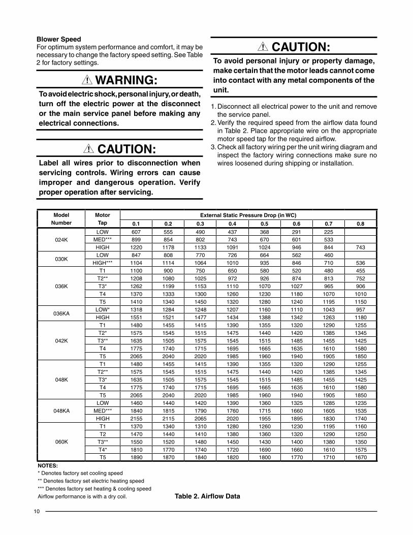
blower SpeedFor optimum system performance and comfort, it may be necessary to change the factory speed setting. See Table 2 for factory settings.
WARNING:To avoid electric shock, personal injury, or death, turn off the electric power at the disconnect or the main service panel before making any electrical connections.
CAUTION:Label all wires prior to disconnection when servicing controls. Wiring errors can cause improper and dangerous operation. Verifyproper operation after servicing.
ModelNumber
MotorTap
External Static Pressure Drop (in WC)
0.1 0.2 0.3 0.4 0.5 0.6 0.7 0.8
024KLOW 607 555 490 437 368 291 225
MED*** 899 854 802 743 670 601 533HIGH 1220 1178 1133 1091 1024 946 844 743
030KLOW 847 808 770 726 664 562 460
HIGH*** 1104 1114 1064 1010 935 846 710 536
036K
T1 1100 900 750 650 580 520 480 455T2** 1208 1080 1025 972 926 874 813 752T3* 1262 1199 1153 1110 1070 1027 965 906T4 1370 1333 1300 1260 1230 1180 1070 1010T5 1410 1340 1450 1320 1280 1240 1195 1150
036KALOW* 1318 1284 1248 1207 1160 1110 1043 957HIGH 1551 1521 1477 1434 1388 1342 1263 1180
042K
T1 1480 1455 1415 1390 1355 1320 1290 1255T2* 1575 1545 1515 1475 1440 1420 1385 1345T3** 1635 1505 1575 1545 1515 1485 1455 1425T4 1775 1740 1715 1695 1665 1635 1610 1580T5 2065 2040 2020 1985 1960 1940 1905 1850
048K
T1 1480 1455 1415 1390 1355 1320 1290 1255T2** 1575 1545 1515 1475 1440 1420 1385 1345T3* 1635 1505 1575 1545 1515 1485 1455 1425T4 1775 1740 1715 1695 1665 1635 1610 1580T5 2065 2040 2020 1985 1960 1940 1905 1850
048KALOW 1460 1440 1420 1390 1360 1325 1285 1235
MED*** 1840 1815 1790 1760 1715 1660 1605 1535HIGH 2155 2115 2065 2020 1955 1895 1830 1740
060K
T1 1370 1340 1310 1280 1260 1230 1195 1160T2 1470 1440 1410 1380 1360 1320 1290 1250
T3** 1550 1520 1480 1450 1430 1400 1380 1350T4* 1810 1770 1740 1720 1690 1660 1610 1575T5 1890 1870 1840 1820 1800 1770 1710 1670
NOTES:* Denotes factory set cooling speed** Denotes factory set electric heating speed*** Denotes factory set heating & cooling speedAirflow performance is with a dry coil. Table 2. Airflow Data
CAUTION:To avoid personal injury or property damage, make certain that the motor leads cannot come into contact with any metal components of the unit.
1. Disconnect all electrical power to the unit and remove the service panel.
2. Verify the required speed from the airflow data found in Table 2. Place appropriate wire on the appropriate motor speed tap for the required airflow.
3. Check all factory wiring per the unit wiring diagram and inspect the factory wiring connections make sure no wires loosened during shipping or installation.

11
STARTUP & ADjUSTMENTSPre-Start ChecklistThe following check list should be observed prior to starting the unit.√ Is the unit level? Unit should be level or slightly slanted
toward the drain for proper condensate drainage.√ Is the unit installed with the proper clearances as listed
on pages 4 - 5?√ Is the wiring correct according to the wiring diagram
and electrical codes?√ Are all the wiring connections tight? Check the condenser
fan to make sure it turns freely. √ Is the overcurrent protection properly sized?√ Is the thermostat wired correctly? Is it installed in a
proper location?
Start-Up ProcedureThe control circuit consists of an anti-short cycle timer that will not let the compressor re-start before 5 minutes have elapsed.1. Set the system mode to OFF and the temperature mode
to its highest setting.2. Turn power on at the disconnect switch.3. Set the system mode to ON or COOL.4. Set the temperature mode below room temperature.
Verify that the indoor blower, outdoor fan, and compressor energize and the cooling function starts.
5. Verify the discharge air grilles are adjusted and the system air is balanced.
6. Verify the duct work has no air leaks.7. Verify the condensate drain is installed correctly and
functions properly.8. Set the temperature mode above room temperature.
The unit should stop.9. Instruct the homeowner on unit and thermostat operation
and filter servicing.
Air CirculationLeave the thermostat system mode on OFF, and set the fan mode to ON. Blower should run continuously. Check the air delivery at the supply registers and adjust register openings for balanced air distribution. Examine ducts for leaks or obstruction if insufficient air is detected.
Set the thermostat fan mode to AUTO. The blower should stop running.
System HeatingSet the thermostat system mode to HEAT and the fan mode to AUTO. Change the thermostat temperature selector above the existing room temperature and check for the discharge of warm air at the supply registers.
System CoolingSet the thermostat’s system mode to COOL and the fan mode to AUTO. Change the thermostat temperature selector below the existing room temperature. Allow the cooling system to operate for several minutes and check for the discharge of cool air at the supply registers.
Short Cycle ProtectionThe control circuit is equipped with a time-delay feature for protection against short cycling. With the system operating in the cooling mode, gradually raise the thermostat temperature setting until the whole system de-energizes. Immediately lower the thermostat temperature to the original setting and verify that the indoor blower is energized. After approximately 5 minutes the compressor and the outdoor fan will energize.
Emergency Heat(Available only when Electric heat is supplied) Set the thermostat’s system mode to EM HT and the fan mode to either AUTO (intermittent air) or to ON (continuous air). Change the thermostat’s temperature selector above the existing room temperature and check the following:1. The thermostat auxiliary heat light (RED) should be on.2. The heat pump compressor and the fan should not run;
low voltage circuit remains energized.3. The blower will run according to the thermostat’s fan
mode setting.
Anti Short Cycle Timer TestThe 5 minute time delay feature can be bypassed by shorting the TEST pins together.
Heating ModeWhen the TEST pins are shorted together for more than 1 second, the control will switch between defrost mode and heating mode.
Cooling ModeWhen the TEST pins are shorted together for more than 1 second, the Anti Short Cycle Timer will be bypassed.
Adjustment of Refrigerant Charge
CAUTION:This heat pump contains liquid and gaseous refrigerant under pressure. Adjustment of refrigerant charge should only be attempted by qualified, trained personnel thoroughly familiar with the equipment and safe responsible refrigerant handling procedures. Under no circumstances should the homeowner attempt to install and/or service this equipment. Failure to comply with this warning could result in equipment damage, personal injury, or death.
• Theunitmustbechargedwhilebothfirstandsecondstages are operating.
• Toachieveratedcapacityandefficiencythecompressormust be exposed to refrigerant for at least 24 hours prior to running and then must be run for a minimum of 12 hours.
12
UNIT MAINTENANCE
WARNING:To prevent electrical shock, personal injury, or death, disconnect all electrical power to the unit before performing any maintenance or service. The unit may have more than one electrical supply.
Proper maintenance is important to achieve optimum performance from the heat pump. The ability to properly perform maintenance on this equipment requires certain mechanical skills and tools. If you do not possess these skills, contact your dealer for maintenance. Consult your local dealer about the availability of maintenance contracts. Routine maintenance should include the following:• Inspectandcleanorreplaceairfiltersatthebeginning
of each heating and cooling season, or more frequently if required.
• Inspectthecondensatedrainandoutdoorcoilatthebeginning of each cooling season. Remove any debris. Clean the outdoor coil and louvers as necessary using a mild detergent and water. Rinse thoroughly with water.
• Inspecttheelectricalconnectionsfortightnessatthebeginning of each heating and cooling season. Service as necessary.
Charging the Unit in AC Mode with Outdoor Temperatures Above 65° F1. With the system operating at steady-state, measure the
liquid refrigerant pressure in psig at the service valve.2. Measure the liquid refrigerant temperature (° F) at the
service valve.3. For the temperature measured, determine the required
liquid refrigerant pressure from the appropriate charging charts. For cooling operation, see Tables 3 - 8 or Figure 9 (pages 14 - 16).
• Ifthepressuremeasuredinstep1isgreaterthantherequired liquid refrigerant pressure determined in step 3, then there is too much charge in the system. Remove refrigerant and repeat steps 1 through 3 until the system is correctly charged.
• If the pressure measured in step 1 is less than therequired liquid refrigerant pressure determined in step 3, then there is too little charge in the system. Add refrigerant and repeat steps 1 through 3 until the system is correctly charged.
Charging the Unit in Heating Mode1. Evacuate the refrigerant system.2. Weigh in the proper charge as shown on the unit rating
plate. Use the charging charts for heating mode of operation as a guide (Tables 9 - 15, pages 17 - 20). Tables reflect conditions at high speed operation. Unit charge MUST be verified in cooling season.
3. Verify the unit is operating properly according to the System Heating section on page 11.
COMPONENT FUNCTIONSLow Pressure Switch - This switch is factory installed and located in the suction line internal to the unit. The switch is designed to protect the compressor if a loss of charge occurs. Under normal conditions, the switch is closed.
If the suction pressure falls below 5 psig, then the switch will open and de-energize the unit. The switch will close again once the suction pressure increases above 20 psig. The low pressure switch interrupts the thermostat inputs to the unit. NOTE: When the switch opens and then closes, there will be a 5 minute short cycling delay before the unit can energize.
High Pressure Switch - This switch is factory installed and located in the compressor discharge line internal to the unit. The switch is designed to de-energize the system when very high pressures occur during abnormal conditions. Under normal conditions, the switch is closed.
If the discharge pressure rises above 650 psig, the switch will open and de-energize the unit. The switch will close again once the discharge pressure decreases to 460 psig. The high pressure switch interrupts the thermostat inputs to the unit. NOTE: When the switch opens and then closes, there will be a 5 minute short cycling delay before the unit can energize.
CAUTION:The unit should never be operated without a filter in the return air system. Replace disposable filters with the same type and size.
• Donotattempttoaddadditionaloiltomotorsunequippedwith oil tubes. The compressor is hermetically sealed at the factory and does not require lubrication.

13
FIGURES & TAbLES
Model Number Length (L) Width (W) Height (H) A b
024K 49 35 22.2 40.15 7.61030K 49 35 30.2 40.15 7.61
036K/KA 49 35 30.2 35.02 2.48042K 49 35 30.2 35.02 2.48
048K/KA 49 35 34.2 35.02 2.48060K 49 35 38.2 35.02 2.48
9.15
9.04 17.50
14" diameter Return Duct Opening
12" diameter Supply DuctOpening
3.0 5.5
1"3.15
A
B
Back(Duct)View
L
W
18.01
Electric Heater Power SupplyPower Supply
Low Voltage Supply
ControlAccessPanel
Blower Access PanelH
17.86
15.36
10.10
3/4" NPTDrain Connection
1"
12.13
1.383.2
3.2 5.29
Figure 8. Physical Data & Unit Dimensions
TopView
SideView

14
2 TON MODELS
Suct.PreSS.
OutDOOr teMPerAture (° F)
70 75 80 85 90 95 100 105
Liq.PreSS.
DiS.teMP.
Liq.PreSS.
DiS.teMP.
Liq.PreSS.
DiS.teMP.
Liq.PreSS.
DiS.teMP.
Liq.PreSS.
DiS.teMP.
Liq.PreSS.
DiS.teMP.
Liq.PreSS.
DiS.teMP.
Liq.PreSS.
DiS.teMP.
136 260 136138 262 142 283 140140 265 147 285 145 306 143142 270 146 288 150 309 148 330 147144 274 148 293 150 311 153 332 152 353 151146 296 154 315 155 334 156 355 155 376 155148 319 158 338 159 357 160 378 159 399 159150 342 163 361 163 380 163 401 163 422 163152 345 167 364 167 383 167 403 167 424 167
154 368 171 387 171 406 171 426 170156 390 175 410 175 429 175158 413 179 432 179160 436 183162
Table 3. Charging Table for 2 Ton Models (024K Series)
2.5 TON MODELS
Suct.PreSS.
OutDOOr teMPerAture (° F)
70 75 80 85 90 95 100 105
Liq.PreSS.
DiS.teMP.
Liq.PreSS.
DiS.teMP.
Liq.PreSS.
DiS.teMP.
Liq.PreSS.
DiS.teMP.
Liq.PreSS.
DiS.teMP.
Liq.PreSS.
DiS.teMP.
Liq.PreSS.
DiS.teMP.
Liq.PreSS.
DiS.teMP.
139 258 115141 260 121 281 121143 262 126 283 126 304 126145 266 129 285 131 306 131 327 132147 269 131 289 134 308 136 329 136 350 137149 292 137 312 139 331 141 352 142 373 143151 315 143 334 145 354 146 375 147 396 148153 338 148 357 150 377 151 398 152 419 154155 341 152 361 154 380 155 400 156 421 157
157 364 158 384 159 403 161 423 161159 387 163 407 165 426 166161 410 169 430 170163 433 175165
Table 4. Charging Table for 2.5 Ton Models (030K Series)
REFRIGERANT CHARGING TAbLES - COOLING MODE
Shaded boxes indicate flooded conditions.
Rated design values. The suction pressure will be lower than design value if indoor air flow, entering dry bulb, or entering wet bulb temperature are lower than design.
1. All pressures are listed psig and all temperatures in °F2. Discharge temperatures greater than charted values indicate an undercharged system.

15
3 TON MODELS (WITH ECM MOTOR)
Suct.PreSS.
OutDOOr teMPerAture (° F)
70 75 80 85 90 95 100 105
Liq.PreSS.
DiS.teMP.
Liq.PreSS.
DiS.teMP.
Liq.PreSS.
DiS.teMP.
Liq.PreSS.
DiS.teMP.
Liq.PreSS.
DiS.teMP.
Liq.PreSS.
DiS.teMP.
Liq.PreSS.
DiS.teMP.
Liq.PreSS.
DiS.teMP.
138 267 113140 269 118 290 119142 271 123 292 124 314 125144 272 131 294 129 316 130 337 131146 276 133 296 135 318 135 339 136 360 137148 300 138 320 140 341 141 362 142 384 143150 323 143 344 145 364 146 386 147 407 148152 347 148 367 150 388 151 409 152 430 154154 351 152 371 154 391 155 411 156 432 157
156 374 158 395 159 415 161 434 161158 398 163 418 165 439 166160 422 169 442 171162 445 175164
3 TON MODELS (WITH PSC MOTOR)135 258 119137 260 125 282 125139 262 130 284 130 305 131141 265 134 286 135 308 135 329 136143 269 136 289 139 310 140 331 141 353 142145 293 142 313 144 333 145 355 146 377 147147 316 147 337 149 357 150 379 151 401 152149 340 153 361 154 391 155 403 156 424 158151 344 156 364 158 384 159 405 160 426 162
153 367 162 388 164 408 165 428 165155 391 168 412 169 432 170157 415 173 435 174159 439 179161
Table 5. Charging Table for 3 Ton Models (036K / 036KA Series)
3.5 TON MODELS
Suct.PreSS.
OutDOOr teMPerAture (° F)
70 75 80 85 90 95 100 105
Liq.PreSS.
DiS.teMP.
Liq.PreSS.
DiS.teMP.
Liq.PreSS.
DiS.teMP.
Liq.PreSS.
DiS.teMP.
Liq.PreSS.
DiS.teMP.
Liq.PreSS.
DiS.teMP.
Liq.PreSS.
DiS.teMP.
Liq.PreSS.
DiS.teMP.
134 269 129136 271 135 293 134138 274 140 295 139 316 138140 279 139 297 144 318 143 340 143142 282 142 302 145 320 148 342 148 363 148144 305 148 325 150 344 152 365 152 387 153146 328 154 348 155 367 156 389 157 410 157148 351 159 371 160 391 161 412 161 434 162150 355 163 374 164 394 165 414 165 436 166
152 378 168 398 169 417 170 438 170154 401 173 421 174 440 174156 424 178 444 179158 447 183160
Table 6. Charging Table for 3.5 Ton Models (042K Series)
16
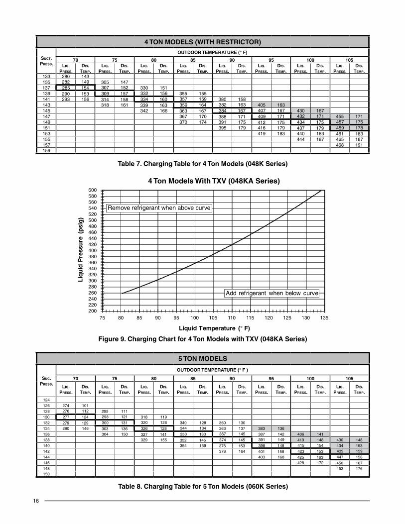
4 TON MODELS (WITH RESTRICTOR)
Suct.PreSS.
OutDOOr teMPerAture (° F)
70 75 80 85 90 95 100 105Liq.
PreSS.DiS.
teMP.Liq.
PreSS.DiS.
teMP.Liq.
PreSS.DiS.
teMP.Liq.
PreSS.DiS.
teMP.Liq.
PreSS.DiS.
teMP.Liq.
PreSS.DiS.
teMP.Liq.
PreSS.DiS.
teMP.Liq.
PreSS.DiS.
teMP.133 280 143135 282 149 305 147137 285 154 307 152 330 151139 290 153 309 157 332 156 355 155141 293 156 314 158 334 160 357 159 380 158143 318 161 339 163 359 164 382 163 405 163145 342 166 363 167 384 167 407 167 430 167147 367 170 388 171 409 171 432 171 455 171149 370 174 391 175 412 175 434 175 457 175151 395 179 416 179 437 179 459 178153 419 183 440 183 461 183155 444 187 465 187157 468 191159
Table 7. Charging Table for 4 Ton Models (048K Series)
5 TON MODELS
Suc.PreSS.
OutDOOr teMPerAture (° F )
70 75 80 85 90 95 100 105
Liq.PreSS.
DiS.teMP.
Liq.PreSS.
DiS.teMP.
Liq.PreSS.
DiS.teMP.
Liq.PreSS.
DiS.teMP.
Liq.PreSS.
DiS.teMP.
Liq.PreSS.
DiS.teMP.
Liq.PreSS.
DiS.teMP.
Liq.PreSS.
DiS.teMP.
124126 274 101128 276 112 295 111130 277 124 298 121 318 119132 279 129 300 131 320 128 340 128 360 130134 280 146 303 136 326 128 344 134 363 137 383 136136 304 150 327 141 350 133 367 145 387 142 406 141138 329 155 352 145 374 145 391 149 410 148 430 148140 354 159 376 153 398 148 415 154 434 153142 378 164 401 158 423 153 439 159
144 403 168 425 163 447 158146 428 172 450 167148 452 176150
Table 8. Charging Table for 5 Ton Models (060K Series)
Figure9.ChargingChartfor4TonModelswithTXV(048KASeries)
200220240260280300320340360380400420440460480500520540560580600
75 80 85 90 95 100 105 110 115 120 125 130 135
Liq
uid
Pre
ssu
re (
psi
g)
Liquid Temperature (° F)
Add refrigerant when below curve
4 Ton Models With TXV (048KA Series)
Remove refrigerant when above curve

17
2.5
TON
MO
DE
LS
OU
TD
OO
R T
EM
PE
RA
TU
RE
(°
F)
010
2030
4050
60
Su
c.P
ress
Liq
.P
ress
.D
is.
Tem
p.
Su
c.P
ress
.L
iq.
Pre
ss.
Dis
.Te
mp
.S
uc.
Pre
ss.
Liq
.P
ress
.D
is.
Tem
p.
Su
c.P
ress
.L
iq.
Pre
ss.
Dis
.Te
mp
.S
uc.
Pre
ss.
Liq
.P
ress
.D
is.
Tem
p.
Su
c.P
ress
.L
iq.
Pre
ss.
Dis
.Te
mp
.S
uc.
Pre
ss.
Liq
.P
ress
.D
is.
Tem
p.
4722
613
755
235
134
6224
513
069
254
126
8526
013
110
928
614
313
431
315
5
4823
313
556
241
132
6325
012
870
258
124
8626
712
811
029
313
813
532
014
9
4924
013
357
247
130
6425
412
671
262
122
8727
412
511
130
013
413
632
714
3
5024
713
158
253
128
6525
912
472
265
120
8828
112
211
230
712
913
733
413
7
5125
412
959
259
126
6626
412
273
269
118
8928
811
911
331
412
513
834
113
052
261
127
6026
512
467
269
120
7427
311
690
295
117
114
321
120
139
348
124
5326
812
561
271
122
6827
411
875
276
114
9130
211
411
532
811
614
035
511
8
Tab
le 1
0. C
har
gin
g T
able
for
2.5
Ton
Mo
del
s (0
30K
Ser
ies)
2 TO
N M
OD
EL
S
OU
TD
OO
R T
EM
PE
RA
TU
RE
(°
F)
010
2030
4050
60
Su
c.P
ress
Liq
. P
ress
.D
is.
Tem
p.
Su
c.P
ress
.L
iq.
Pre
ss.
Dis
.Te
mp
.S
uc.
Pre
ss.
Liq
. P
ress
.D
is.
Tem
p.
Su
c.P
ress
.L
iq.
Pre
ss.
Dis
.Te
mp
.S
uc.
Pre
ss.
Liq
. P
ress
.D
is.
Tem
p.
Su
c.P
ress
.L
iq.
Pre
ss.
Dis
.Te
mp
.S
uc.
Pre
ss.
Liq
. P
ress
.D
is.
Tem
p.
3720
911
451
232
121
6525
412
778
277
133
9429
214
211
032
215
412
735
316
538
216
112
5223
811
966
259
125
7928
113
195
299
140
111
329
149
128
360
159
3922
311
053
244
117
6726
412
380
284
129
9630
613
711
233
614
512
936
715
3
4023
010
854
250
115
6826
912
181
288
127
9731
313
411
334
314
013
037
414
741
237
106
5525
511
369
274
119
8229
212
598
320
131
114
350
136
131
381
140
4224
410
456
261
111
7027
811
783
295
123
9932
712
811
535
713
113
238
813
443
251
102
5726
710
971
283
115
8429
912
110
033
412
511
636
412
713
339
512
8
Tab
le 9
. Ch
arg
ing
Tab
le fo
r 2
Ton
Mo
del
s (0
24K
Ser
ies)
RE
FR
IGE
RA
NT
CH
AR
GIN
G T
Ab
LE
S -
HE
AT
ING
MO
DE
Sha
ded
boxe
s in
dica
te fl
oode
d co
nditi
ons.
Rat
ed d
esig
n va
lues
. Suc
tion
pres
sure
will
var
y fr
om d
esig
n va
lue
if ou
tdoo
r ai
r flo
w, e
nter
ing
dry
bulb
, or
ente
ring
wet
bul
b te
mpe
ratu
res
vary
.
1. A
ll pr
essu
res
are
liste
d ps
ig a
nd a
ll te
mpe
ratu
res
in °
F2.
Dis
char
ge te
mpe
ratu
res
grea
ter
than
cha
rted
val
ues
indi
cate
an
unde
rcha
rged
sys
tem
.

18
RE
FR
IGE
RA
NT
CH
AR
GIN
G T
Ab
LE
S -
HE
AT
ING
MO
DE
Sha
ded
boxe
s in
dica
te fl
oode
d co
nditi
ons.
Rat
ed d
esig
n va
lues
. Suc
tion
pres
sure
will
var
y fr
om d
esig
n va
lue
if ou
tdoo
r ai
r flo
w, e
nter
ing
dry
bulb
, or
ente
ring
wet
bul
b te
mpe
ratu
res
vary
.
1. A
ll pr
essu
res
are
liste
d ps
ig a
nd a
ll te
mpe
ratu
res
in °
F2.
Dis
char
ge te
mpe
ratu
res
grea
ter
than
cha
rted
val
ues
indi
cate
an
unde
rcha
rged
sys
tem
.
3 TO
N M
OD
EL
S
OU
TD
OO
R T
EM
PE
RA
TU
RE
(°
F)
010
2030
4050
60
Su
c.P
ress
Liq
.P
ress
.D
is.
Tem
p.
Su
c.P
ress
.L
iq.
Pre
ss.
Dis
.Te
mp
.S
uc.
Pre
ss.
Liq
.P
ress
.D
is.
Tem
p.
Su
c.P
ress
.L
iq.
Pre
ss.
Dis
.Te
mp
.S
uc.
Pre
ss.
Liq
.P
ress
.D
is.
Tem
p.
Su
c.P
ress
.L
iq.
Pre
ss.
Dis
.Te
mp
.S
uc.
Pre
ss.
Liq
.P
ress
.D
is.
Tem
p.
3421
612
749
234
128
6325
112
978
269
130
9327
513
510
929
414
512
431
315
435
223
125
5024
012
664
256
127
7927
212
894
282
133
110
301
140
125
320
148
3623
012
351
246
124
6526
112
580
276
126
9528
913
011
130
813
612
632
714
2
3723
712
152
251
122
6626
612
381
280
124
9629
612
711
231
513
112
733
413
638
244
119
5325
712
067
270
121
8228
312
297
303
124
113
322
127
128
341
129
3925
111
754
263
118
6827
511
983
287
120
9831
012
111
432
912
212
934
812
340
258
115
5526
911
669
280
117
8429
111
899
317
118
115
336
118
130
355
117
3 TO
N M
OD
EL
S (
KA
SE
RIE
S)
OU
TD
OO
R T
EM
PE
RA
TU
RE
(°
F)
010
2030
4050
60
Su
c.P
ress
Liq
.P
ress
.D
is.
Tem
p.
Su
c.P
ress
.L
iq.
Pre
ss.
Dis
.Te
mp
.S
uc.
Pre
ss.
Liq
.P
ress
.D
is.
Tem
p.
Su
c.P
ress
.L
iq.
Pre
ss.
Dis
.Te
mp
.S
uc.
Pre
ss.
Liq
.P
ress
.D
is.
Tem
p.
Su
c.P
ress
.L
iq.
Pre
ss.
Dis
.Te
mp
.S
uc.
Pre
ss.
Liq
.P
ress
.D
is.
Tem
p.
3221
612
947
234
130
6225
213
176
270
132
9227
813
710
829
714
712
431
715
733
223
127
4824
012
863
257
129
7727
413
093
285
135
109
304
143
125
324
151
3423
012
549
246
126
6426
212
778
278
128
9429
213
211
031
113
812
633
114
5
3523
712
350
252
124
6526
712
579
281
126
9529
912
911
131
813
412
733
813
836
244
121
5125
812
266
271
123
8028
512
496
306
126
112
325
129
128
345
132
3725
111
952
264
120
6727
612
181
289
122
9731
312
311
333
212
512
935
212
638
258
117
5326
911
868
281
119
8229
212
098
320
120
114
339
120
130
359
120
Tab
le 1
1. C
har
gin
g T
able
for
3 To
n M
od
els
(036
K &
KA
Ser
ies)

19
Tab
le 1
2. C
har
gin
g T
able
for
3.5
Ton
Mo
del
s (0
42K
Ser
ies)
3.5
TON
MO
DE
LS
OU
TD
OO
R T
EM
PE
RA
TU
RE
(°.
F)
010
2030
4050
60
Su
c.P
ress
Liq
.P
ress
.D
is.
Tem
p.
Su
c.P
ress
.L
iq.
Pre
ss.
Dis
.Te
mp
.S
uc.
Pre
ss.
Liq
.P
ress
.D
is.
Tem
p.
Su
c.P
ress
.L
iq.
Pre
ss.
Dis
.Te
mp
.S
uc.
Pre
ss.
Liq
. P
ress
.D
is.
Tem
p.
Su
c.P
ress
.L
iq.
Pre
ss.
Dis
.Te
mp
.S
uc.
Pre
ss.
Liq
. P
ress
.D
is.
Tem
p.
3321
713
648
239
137
6326
113
878
283
139
9229
514
410
731
915
412
134
316
3
3422
413
449
245
135
6426
613
679
287
137
9330
214
110
832
614
912
235
015
7
3523
113
250
251
133
6527
113
480
290
135
9430
913
910
933
314
512
335
715
1
3623
813
051
257
131
6627
513
281
294
133
9531
613
611
034
014
012
436
414
5
3724
512
852
262
129
6728
013
082
298
131
9632
313
311
134
713
612
537
113
938
252
126
5326
812
768
285
128
8330
112
997
330
130
112
354
131
126
378
133
3925
912
454
274
125
6929
012
684
305
127
9833
712
711
336
112
712
738
512
6
RE
FR
IGE
RA
NT
CH
AR
GIN
G T
Ab
LE
S -
HE
AT
ING
MO
DE
Sha
ded
boxe
s in
dica
te fl
oode
d co
nditi
ons.
Rat
ed d
esig
n va
lues
. Suc
tion
pres
sure
will
var
y fr
om d
esig
n va
lue
if ou
tdoo
r ai
r flo
w, e
nter
ing
dry
bulb
, or
ente
ring
wet
bul
b te
mpe
ratu
res
vary
.
1. A
ll pr
essu
res
are
liste
d ps
ig a
nd a
ll te
mpe
ratu
res
in °
F2.
Dis
char
ge te
mpe
ratu
res
grea
ter
than
cha
rted
val
ues
indi
cate
an
unde
rcha
rged
sys
tem
.
4 TO
N M
OD
EL
S
OU
TD
OO
R T
EM
PE
RA
TU
RE
(°
F)
010
2030
4050
60
Su
c.P
ress
Liq
.P
ress
.D
is.
Tem
p.
Su
c.P
ress
.L
iq.
Pre
ss.
Dis
.Te
mp
.S
uc.
Pre
ss.
Liq
.P
ress
.D
is.
Tem
p.
Su
c.P
ress
.L
iq.
Pre
ss.
Dis
.Te
mp
.S
uc.
Pre
ss.
Liq
.P
ress
.D
is.
Tem
p.
Su
c.P
ress
.L
iq.
Pre
ss.
Dis
.Te
mp
.S
uc.
Pre
ss.
Liq
. P
ress
.D
is.
Tem
p.
3321
812
746
236
129
5925
413
172
272
133
8728
513
910
531
514
812
234
615
8
3422
512
547
242
127
6025
912
973
276
131
8829
213
610
632
214
412
335
315
1
3523
212
348
248
125
6126
412
774
279
129
8929
913
310
732
913
912
436
014
5
3623
912
149
254
123
6226
812
575
283
127
9030
613
110
833
613
512
536
713
9
3724
611
950
259
121
6327
312
376
287
125
9131
312
810
934
313
012
637
413
338
253
117
5126
511
964
278
121
7729
012
392
320
125
110
350
126
127
381
127
3926
011
552
271
117
6528
311
978
294
121
9332
712
211
135
712
112
838
812
1
Tab
le 1
3. C
har
gin
g T
able
for
4 To
n M
od
els
(048
K S
erie
s)

20
Tab
le 1
5. C
har
gin
g T
able
for
5 To
n M
od
els
(060
K S
erie
s)
5 TO
N M
OD
EL
S
OU
TD
OO
R T
EM
PE
RA
TU
RE
(°
F)
010
2030
4050
60
Su
c.P
ress
Liq
. P
ress
.D
is.
Tem
p.
Su
c.P
ress
.L
iq.
Pre
ss.
Dis
.Te
mp
.S
uc.
Pre
ss.
Liq
. P
ress
.D
is.
Tem
p.
Su
c.P
ress
.L
iq.
Pre
ss.
Dis
.Te
mp
.S
uc.
Pre
ss.
Liq
. P
ress
.D
is.
Tem
p.
Su
c.P
ress
.L
iq.
Pre
ss.
Dis
.Te
mp
.S
uc.
Pre
ss.
Liq
. P
ress
.D
is.
Tem
p.
3120
313
444
233
139
5726
414
370
294
148
8431
316
210
034
418
611
637
521
0
3221
013
245
239
137
5826
914
171
298
146
8532
015
910
135
118
211
738
220
4
3321
713
046
245
135
5927
313
972
302
144
8632
715
610
235
817
711
838
919
8
3422
412
847
251
133
6027
813
773
305
142
8733
415
410
336
517
311
939
619
2
3523
112
648
257
131
6128
313
574
309
140
8834
115
110
437
216
812
040
318
636
238
124
4926
312
962
288
133
7531
313
889
348
148
105
379
164
121
410
180
3724
512
250
269
127
6329
313
176
316
136
9035
514
510
638
615
912
241
717
3
RE
FR
IGE
RA
NT
CH
AR
GIN
G T
Ab
LE
S -
HE
AT
ING
MO
DE
Sha
ded
boxe
s in
dica
te fl
oode
d co
nditi
ons.
Rat
ed d
esig
n va
lues
. Suc
tion
pres
sure
will
var
y fr
om d
esig
n va
lue
if ou
tdoo
r ai
r flo
w, e
nter
ing
dry
bulb
, or
ente
ring
wet
bul
b te
mpe
ratu
res
vary
.
1. A
ll pr
essu
res
are
liste
d ps
ig a
nd a
ll te
mpe
ratu
res
in °
F2.
Dis
char
ge te
mpe
ratu
res
grea
ter
than
cha
rted
val
ues
indi
cate
an
unde
rcha
rged
sys
tem
.
4 TO
N M
OD
EL
S (
KA
SE
RIE
S)
OU
TD
OO
R T
EM
PE
RA
TU
RE
(°
F)
010
2030
4050
60
Su
c.P
ress
Liq
.P
ress
.D
is.
Tem
p.
Su
c.P
ress
.L
iq.
Pre
ss.
Dis
.Te
mp
.S
uc.
Pre
ss.
Liq
.P
ress
.D
is.
Tem
p.
Su
c.P
ress
.L
iq.
Pre
ss.
Dis
.Te
mp
.S
uc.
Pre
ss.
Liq
.P
ress
.D
is.
Tem
p.
Su
c.P
ress
.L
iq.
Pre
ss.
Dis
.Te
mp
.S
uc.
Pre
ss.
Liq
. P
ress
.D
is.
Tem
p.
3321
813
747
236
137
6025
413
774
273
137
8928
414
210
631
115
112
333
816
1
3422
513
548
242
135
6125
913
575
276
135
9029
113
910
731
814
712
434
515
5
3523
213
349
248
133
6226
413
376
280
133
9129
813
610
832
514
212
535
214
8
3623
913
150
254
131
6326
913
177
284
131
9230
513
310
933
213
812
635
914
2
3724
612
951
260
129
6427
412
978
287
129
9331
213
111
033
913
312
736
613
638
253
127
5226
612
765
278
127
7929
112
794
319
128
111
346
129
128
373
130
3926
012
553
271
125
6628
312
580
295
125
9532
612
511
235
712
412
938
012
4
Tab
le 1
4. C
har
gin
g T
able
for
4 To
n M
od
els
(048
KA
Ser
ies)
21
ELECTRICAL DIAGRAMS
Figure 10. Wiring Diagram - 2, 2.5, 3, & 4 Ton Models
OU
TD
OO
R F
AN
MO
TOR
4 3 2 18 7 6 59
4 3 2 18 7 6 59
TO “G
” ON
T-S
TAT
3 A
MP
FU
SE
BLO
WE
RR
ELA
Y
BLO
WE
RM
OTO
R
CA
PAC
ITO
R
RE
VE
RS
ING
VA
LVE
CO
IL
DE
FR
OS
TS
EN
SO
RD
UA
LC
APA
CIT
OR
CO
MP
RE
SS
OR
TR
AN
SF
OR
ME
R
240V
24V
CO
MR
EF;
631
849
AM
PA
DA
PT
ER
YC
OW
2R
E
DE
FR
OS
TC
ON
TR
OL
BO
AR
D
DF
TE
RW
2O
YC T
2T
1
DF
1
DF
2
BLU
E
OR
AN
GE
RE
D YE
LLO
W
BLA
CK
H
C
F
C
RS
S R
C
T1
T2L2
L1
BLA
CK
BLA
CK
OU
TD
OO
R T
HE
RM
OS
TAT
(O
N S
ELE
CT
MO
DE
LSB
RO
WN
JU
MP
ER
IS IN
STA
LLE
D)
13
BLA
CK
RE
DR
EDNO
NC
COM YE
LLO
W
YE
LLO
W
HIG
HP
RE
SS
UR
ES
WIT
CH
LOW
PR
ES
SU
RE
SW
ITC
H
(SE
LEC
T M
OD
ELS
ON
LY)
CC
HIF
EQ
UIP
PE
D
BLA
CK
BLA
CK
YE
LLO
W
YE
LLO
W
RO
UT
E W
IRE
INTO
ELE
. BO
X O
N U
NIT
.T
IE E
XT
RA
MAT
ER
IAL
UP
SO
IT IS
OU
T O
F T
HE
WAY
.
BLA
CK
RE
D
BR
OW
N
BR
OW
N
BLU
E
BLU
E
BR
OW
N
RE
D
RE
D
RE
D
RE
D
RE
D
OR
AN
GE
YE
LLO
W
WH
ITE
WH
ITE
WH
ITE
WH
ITE
GR
EY
GR
EY
BR
OW
N
BLA
CK
BLA
CK
BLA
CK
GR
EE
N
YE
LLO
W
BLA
CK
VIOLET
208/
230
VO
LTS
MA
LL
PA
CK
AG
E H
EA
T P
UM
P60
HZ
/SIN
GL
E P
HA
SE
WIR
ING
DIA
GR
AM
NO
TE
S:
1. D
isco
nn
ect
all p
ow
er b
efo
re s
ervi
cin
g.
2. F
or
sup
ply
co
nn
ecti
on
s u
se c
op
per
co
nd
uct
ors
on
ly.
3. N
ot
suti
able
on
sys
tem
s th
at e
xcee
d 1
50V
to
gro
un
d.
.enitertel eriaf ed tnava tnaruoc el repuoC .1
.C°501 rof elbatius srotcudnoc esu seriw tne
mecalper roF .4
2. E
mp
loye
z u
niq
uem
ent
des
co
nd
uct
eurs
e
n c
uiv
er.
9. N
e co
nvi
ent
pas
au
x in
stal
lati
on
s d
e p
lus
d
e 15
0V a
la t
erre
.
7111
360
(Rep
lace
s 71
0838
0)09
10
FIE
LD W
IRIN
G
LEG
EN
D:
LOW
VO
LTA
GE
HIG
H V
OLT
AG
E
Q5R
D/G
Q5R
D/P
PH
2RD
WIT
H P
SC
IND
OO
R M
OT
OR

22
Figure 11. Wiring Diagram - 3.5 & 5 Ton Models
OU
TD
OO
R F
AN
MO
TOR
T1
T4
T3T
2 T5
G
N L
C
L1
T1
L2
T2
4 3 2 18 7 6 59
TO “G
” ON
T-S
TAT
3 A
MP
FU
SE
BLO
WE
RR
ELA
Y
BLO
WE
RM
OTO
R
RE
VE
RS
ING
VA
LVE
CO
IL
DE
FR
OS
TS
EN
SO
R
DU
AL
CA
PAC
ITO
R
CO
MP
RE
SS
OR
TR
AN
SF
OR
ME
R
240V
24V
CO
M OU
TD
OO
R T
HE
RM
OS
TAT
(24)
(ON
SE
LEC
T M
OD
ELS
BR
OW
N J
UM
PE
RIS
INS
TALL
ED
)
CO
MP
RE
SS
OR
CO
NTA
CTO
RY
CO
W2
RE
DE
FR
OS
TC
ON
TR
OL
BO
AR
D
DF
TE
RW
2O
YC T
2T
1
DF
1
DF
2
YC
OW
2R
E
DE
FR
OS
TC
ON
TR
OL
BO
AR
D
DF
TE
RW
2O
YC T
2T
1
DF
1
DF
2
YC
OW
2R
E
DE
FR
OS
TC
ON
TR
OL
BO
AR
D
DF
TE
RW
2O
YC T
2T
1
DF
1
DF
2
BLU
E
OR
AN
GE
RE
D
YE
LLO
W
BLA
CK
H
C
F
C
RS
S
C
R
T1
T2L2
L1
BLA
CK
BLA
CK
HIG
HP
RE
SS
UR
ES
WIT
CH
(28)
LOW
PR
ES
SU
RE
SW
ITC
H (2
5)(S
ELE
CT
MO
DE
LS O
NLY
)
13
BLA
CK
RE
DR
ED
CR
AN
KC
AS
EH
EAT
ER
(IF E
QU
IPP
ED
)
BLA
CK
BLA
CK
RE
DW
HIT
E
BLA
CK
GR
EE
N
RE
D
BLA
CK
BLU
EB
LAC
K
GR
EY
BLA
CK
OR
AN
GE
WH
ITE
RE
D
GR
EE
N/Y
ELL
OW
RE
D
BLU
EO
RA
NG
E
YE
LLO
W
GR
EY
BR
OW
N
RE
D
BR
OW
N
ZH06
TLOV 032/802
4. F
or
rep
lace
men
t w
ires
use
co
nd
uct
ors
su
itab
le fo
r 10
5° C
.5.
On
mo
del
s w
/no
pre
ssu
re s
wit
ch, Y
ello
w J
um
per
co
nn
ects
“Y
” &
“T
1” o
n D
efro
st B
oar
d.
7. C
ou
per
le c
ou
ran
t av
ant
de
fair
e le
tret
ien
. 8.
Em
plo
yez
un
iqu
emen
t d
es c
on
du
cteu
rs
en
cu
ivre
.9.
Ne
con
vien
t p
as a
ux
inst
alla
tio
ns
de
plu
s
de
150V
a la
ter
re.
FIE
LD W
IRIN
G
LEG
EN
D:
LOW
VO
LTA
GE
HIG
H V
OLT
AG
E
WIR
ING
DIA
GR
AM
SM
AL
L P
AC
KA
GE
D H
EA
T P
UM
P-
SIN
GL
E P
HA
SE
NO
TE
S:
1. D
isco
nn
ect
all p
ow
er b
efo
re s
ervi
cin
g.
2. F
or
sup
ply
co
nn
ecti
on
s u
se c
op
per
co
nd
uct
ors
on
ly.
3. N
ot
suit
able
on
sys
tem
s th
at e
xcee
d 1
50V
to
gro
un
d.
7111
350
(Rep
lace
s 71
1107
0)09
10
Q5R
D/G
Q5R
D/P
PH
2RD
WIT
H X
13 IN
DO
OR
MO
TO
R

23
Typical Wiring (Field Supplied) for 1-Stage Cool, 1 Stage Electric Heat
E
O
G
R
Y1
INDOORT-STAT
SUB-BASEGreen
W2
C
DEFROSTBOARD
123456789
BrownOrange
AccessoryHeat Plug
OutdoorThermostat
(Factory Option)
Brown wire not present whenoptional thermostat us used.
Typical Wiring (Field Supplied) for 1-Stage Cool, 2 Stage Electric Heat
INDOORT-STAT
SUB-BASE Green DEFROSTBOARD
123456789
BrownOrange
Accessory Heat Plug
Outdoor Thermostat(Factory Option)
E
O
G
R
Y1
W2
C
Brown wire not present whenoptional thermostat us used.
Optional 2nd Stage Outdoor Thermostat
(Field Supplied)
Figure 12. Typical Thermostat Connections

Specifications & illustrations subject to change without notice or incurring obligations.
O’ Fallon, MO | Printed in U.S.A. (02/11)
INSTALLATION / PERFORMANCE CHECK LIST
REFRIGERATION SYSTEM:Was unit given 24 hr warm up period for crankcase heaters (if applicable)?
YES NO
Stage-1 Liquid Pressure (high side) _____________
Stage-1 Suction Pressure (low side) _____________
Has the owner’s information been reviewed with the customer?
YES NO
Has the Literature Package been left with the unit? YES NO
INSTALLATION ADDRESS:
CITY ________________ STATE _____________
UNIT MODEL # _____________________________
UNIT SERIAL # _____________________________
Unit Installed Minimum clearances per Figure 2 (page 5)?
YES NO
INSTALLER NAME:
CITY ________________STATE ___________
ELECTRICAL SYSTEM:Electrical connections tight? YES NO
Line voltage polarity correct? YES NO
Rated Voltage: ________________________ VOLTS
L1-L2 Volts: __________________________ VOLTS
Has the thermostat been calibrated?
YES NO
Is the thermostat level? YES NO
Is the heat anticipator setting correct?(If Applicable) YES NO
709246A (Replaces 7092460)
INSTALLER:PLEASELEAVETHESEINSTRUCTIONS WITH THE OWNER.