installation instructions roxtec r ug frames -...
TRANSCRIPT
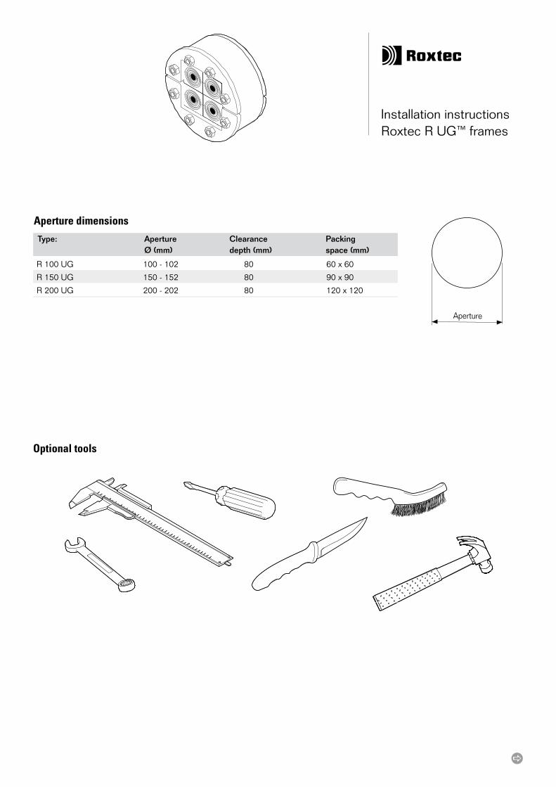
R 100 UG 100 - 102 80 60 x 60
R 150 UG 150 - 152 80 90 x 90
R 200 UG 200 - 202 80 120 x 120
Aperture
Installation instructions Roxtec R UG™ frames
Optional tools
Aperture dimensions
Type: Aperture Clearance Packing Ø (mm) depth (mm) space (mm)
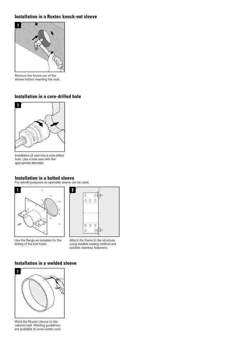
Installation in a core-drilled hole
Installation in a Roxtec knock-out sleeve
Installation in a welded sleeve
1
Weld the Roxtec sleeve to the cabinet/wall. Welding guidelines are available at www.roxtec.com.
1
Installation of seal into a core-drilled hole. Use a hole saw with the appropriate diameter.
1
Remove the knock-out of the sleeve before inserting the seal.
Installation in a bolted sleeveFor retrofit purposes an openable sleeve can be used.
1
Use the flange as template for the drilling of the bolt holes.
2
Attach the frame to the structure using suitable sealing method and suitable stainless fasteners.
12
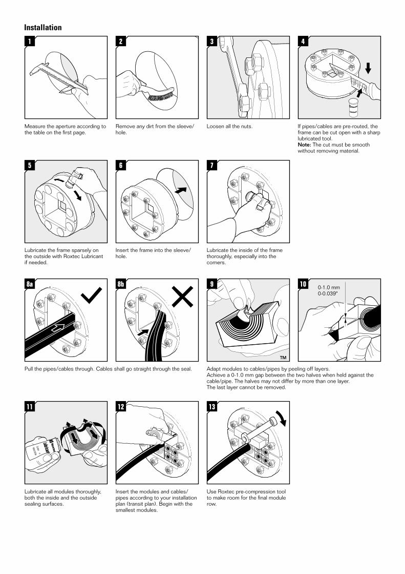
Insert the modules and cables/pipes according to your installation plan (transit plan). Begin with the smallest modules.
9
Adapt modules to cables/pipes by peeling off layers. Achieve a 0-1.0 mm gap between the two halves when held against the cable/pipe. The halves may not differ by more than one layer. The last layer cannot be removed.
10
11
Lubricate all modules thoroughly, both the inside and the outside sealing surfaces.
13
Use Roxtec pre-compression tool to make room for the final module row.
6
Insert the frame into the sleeve/hole.
5
Lubricate the frame sparsely on the outside with Roxtec Lubricant if needed.
7
Lubricate the inside of the frame thoroughly, especially into the corners.
2
Remove any dirt from the sleeve/hole.
1
Measure the aperture according to the table on the first page.
3
Loosen all the nuts.
4
If pipes/cables are pre-routed, the frame can be cut open with a sharp lubricated tool.Note: The cut must be smooth without removing material.
8a
Pull the pipes/cables through. Cables shall go straight through the seal.
8b 0-1.0 mm0-0.039"
Installation
Roxtec ®
and Multidiam
eter ® are registered tradem
arks of Roxtec in S
weden and/or other countries.
Roxtec International AB Box 540, 371 23 Karlskrona, SWEDEN PHONE +46 455 36 67 00, FAX +46 455 820 12 EMAIL [email protected], www.roxtec.com
DISCLAIMER”The Roxtec cable entry sealing system (”the Roxtec system”) is a modular-based system of sealing products consisting of different components. Each and every one of the components is necessary for the best performance of the Roxtec system. The Roxtec system has been certified to resist a number of different hazards. Any such certification, and the ability of the Roxtec system to resist such hazards, is dependent on all components that are installed as a part of the Roxtec system. Thus, the certification is not valid and does not apply unless all components installed as part of the Roxtec system are manufactured by or under license from Roxtec (“authorized manufacturer”). Roxtec gives no performance guarantee with respect to the Roxtec system, unless (I) all compo-nents installed as part of the Roxtec system are manufactured by an authorized manufacturer and (II) the purchaser is in compliance with (a), and (b), below.
(a) During storage, the Roxtec system or part thereof, shall be kept indoors in its original packaging at room temperature.
(b) Installation shall be carried out in accordance with Roxtec installation in-structions in effect from time to time.
The product information provided by Roxtec does not release the purchaser of the Roxtec system, or part thereof, from the obligation to independently determine the suitability of the products for the intended process, installation and/or use.
Roxtec gives no guarantee for the Roxtec system or any part thereof and as-sumes no liability for any loss or damage whatsoever, whether direct, indirect, consequential, loss of profit or otherwise, occurred or caused by the Roxtec systems or installations containing components not manufactured by an authorized manufacturer and/or occurred or caused by the use of the Roxtec system in a manner or for an application other than for which the Roxtec system was designed or intended.
Roxtec expressly excludes any implied warranties of merchantability and fitness for a particular purpose and all other express or implied representations and warranties provided by statute or common law. User determines suitability of the Roxtec system for intended use and assumes all risk and liability in con-nection therewith. In no event shall Roxtec be liable for indirect, consequential, punitive, special, exemplary or incidental damages or losses.”
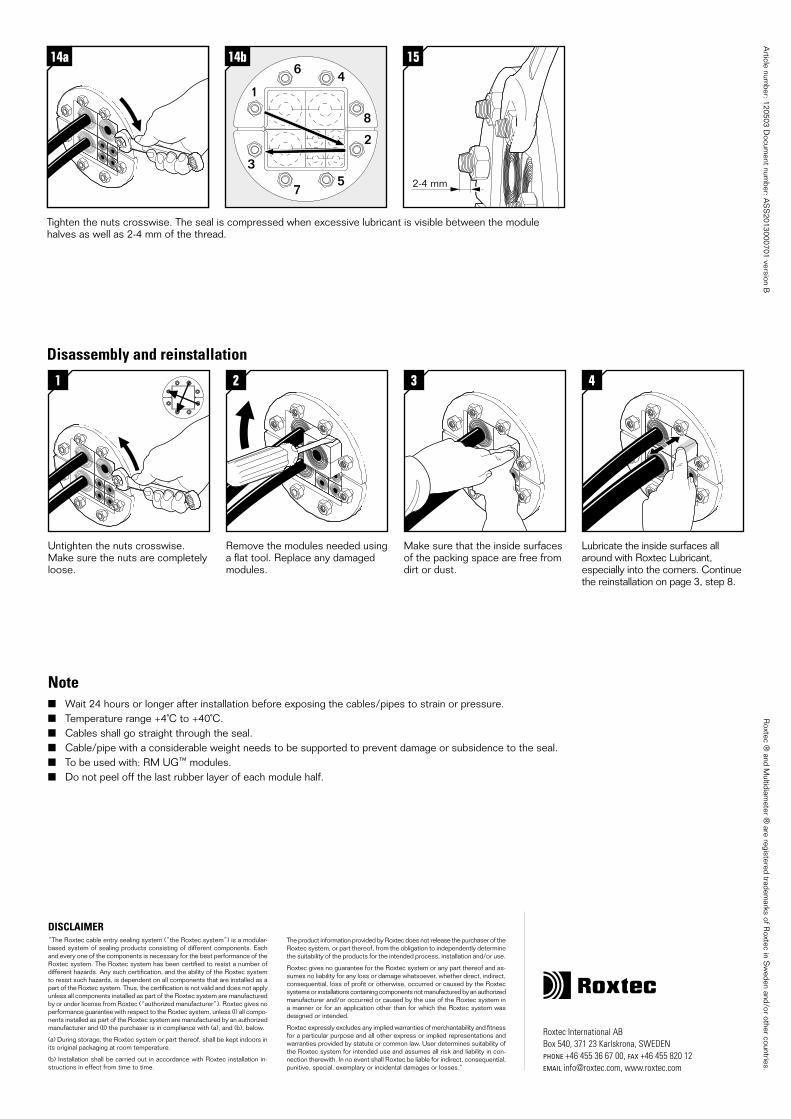
14a
Tighten the nuts crosswise. The seal is compressed when excessive lubricant is visible between the module halves as well as 2-4 mm of the thread.
14a 15
2-4 mm
1
2
3
4
5
6
7
8
14b
Article num
ber: 120503 Docum
ent number: A
SS
2013000701 version B
Disassembly and reinstallation
Note Wait 24 hours or longer after installation before exposing the cables/pipes to strain or pressure. Temperature range +4˚C to +40˚C. Cables shall go straight through the seal. Cable/pipe with a considerable weight needs to be supported to prevent damage or subsidence to the seal. To be used with: RM UG™ modules. Do not peel off the last rubber layer of each module half.
1
Untighten the nuts crosswise. Make sure the nuts are completely loose.
2
Remove the modules needed using a flat tool. Replace any damaged modules.
3
Make sure that the inside surfaces of the packing space are free from dirt or dust.
4
Lubricate the inside surfaces all around with Roxtec Lubricant, especially into the corners. Continue the reinstallation on page 3, step 8.