installation instructions series 3252, 3252sg, hp3253, …
TRANSCRIPT

11M0213
Phone: (800) 262-5151 • Fax: (866) 262-3299crlaurence.com • usalum.com • crl-arch.com
ALUMINUM
INSTALLATION INSTRUCTIONS
SERIES 3252, 3252SG, HP3253, and HP3253SG CURTAIN WALL

The rapidly changing technology within the architectural aluminum products industry demands that U.S. Aluminum reserve the right to revise, discontinue or change any product line, specification or electronic media without prior written notice.
NOTE: Dimensions in parentheses ( ) are millimeters unless otherwise noted.
The following precautions are recommended to protect the material against damage. Following these precautions will help ensure early acceptance of your products and workmanship.
A. HANDLE CAREFULLY. AII aluminum materials at the job site must be stored in a safe place, well removed from possible damage by other trades. Cardboard wrapped or paper interleaved materials must be kept dry.
B. CHECK ARRIVING MATERIALS. Check for quantity counts and keep records of where various materials are stored.
C. KEEP MATERIALS AWAY FROM WATER, MUD, AND SPRAY. Prevent cement, plaster, or other materials from damaging the finish.
D. PROTECT THE MATERIALS AFTER ERECTION. Protect erected frame with polyethylene or canvas splatter screen. Cement, plaster, terrazzo, other alkaline solutions, and acid based materials used to clean masonry are harmful to the finish. If any of these materials come in contact with the aluminum, immediately remove with water and mild soap.
HANDLING, STORAGE, AND PROTECTION OF ALUMINUM
SERIES 3252, 3252SG, HP3253, AND HP3253SG CURTAIN WALL
ALUMINUM02crlaurence.com | usalum.com

1. REVIEW CONTRACT DOCUMENTS. Check shop drawings, installation instructions, architectural drawings, and shipping lists to become thoroughly familiar with the project. The shop drawings take precedence and include specific details for the project. Note any field verified notes on the shop drawings prior to installing. The installation instructions are of a general nature and cover most conditions.
2. INSTALLATION. All materials are to be installed plumb, level, square, and true.
3. BENCH MARKS. All work should start from bench marks and/or column lines as established by the architectural drawings and the general contractor with guaranteed accuracy. Working from these datum points and lines determine: a) The plane of the wall in reference to offset lines provided on each floor. b) The finish floor lines in reference to bench marks on the outer building columns. c) Mullion spacing from both ends of masonry opening to prevent dimensional build-up of daylight opening.
4. STEEL ANCHORS. Steel anchors that weld to steel structure are normally line set before mullions are hung. Outstanding leg of anchors must be at 90 degrees to offset lines. Mullion space should be held to ±1/32" (0.8). Anchor clips vary per job conditions. Follow approved shop drawings for size and location of clips.
5. FIELD WELDING. All field welding must be adequately shielded to avoid any splatter on glass or aluminum. Results will be unsightly and/or structurally unsound. Advise general contractor and other trades accordingly. All field welds of steel anchors must receive touch-up paint (zinc chromate) to avoid rust.
6. SURROUNDING CONDITIONS. Make certain that construction which will receive your materials is in accordance with the contract documents. If not, notify the general contractor in writing and resolve differences before proceeding with work.
7. ISOLATION OF ALUMINUM. Aluminum to be placed in direct contact with uncured masonry or incompatible materials should be isolated with a heavy coat of zinc chromate or bituminous paint.
8. SEALANTS. Sealants must be compatible with all materials with which they have contact, including other sealant surfaces. Consult with sealant manufacturer for recommendations relative to joint size, shelf life, compatibility, cleaning, priming, tooling, adhesion, etc. It is the responsibility of the Glazing Contractor to submit a statement from the sealant manufacturer indicating that glass and glazing materials have been tested for compatibility and adhesion with glazing sealants, and interpreting test results relative to material performance, including recommendations for primers and substrate preparation required to obtain adhesion. The chemical compatibility of all glazing materials and framing sealants with each other and with like materials used in glass fabrication must be established. This is required on every project.
9. FASTENING. Within the body of these instructions "fastening" means any method of securing one part to another or to adjacent materials. Only those fasteners used within the system are specified in these instructions. Due to the varying perimeter conditions and performance requirements, perimeter and anchor fasteners are not specified in these instructions. For perimeter and anchor fasteners refer to the shop drawings or consult the fastener supplier.
10. BUILDING CODES. Due to the diversity in state/provincial, local, and federal laws and codes that govern the design and application of architectural products, it is the responsibility of the individual architect, owner, and installer to assure that products selected for use on projects comply with all the applicable building codes and laws. U.S. Aluminum exercises no control over the use or application of its products, glazing materials, and operating hardware, and assumes no responsibility thereof.
11. EXPANSION JOlNTS. Expansion joints and perimeter seals shown In these instructions and in the shop drawings are shown at normal size. Actual dimensions may vary due to perimeter conditions and/or difference in metal temperature between the time of fabrication and the time of installation. Gaps between expansion members should be based on temperature at time of installation.
12. WATER HOSE TEST. As soon as representative amount of the wall has been glazed (500 square feet or 46.5 m2) a water hose test should be conducted in accordance with AAMA 501.2 specifications to check the installation. On all jobs the hose test should be repeated every 500 square feet (46.5 m2) during the glazing operation.
13. COORDINATION WITH OTHER TRADES. Coordinate with the general contractor any sequence with other trades which offset curtain wall installation (i.e. fire proofing, back-up walls, partitions, ceilings, mechanical ducts, converters, etc.).
14. CARE AND MAINTENANCE. Final cleaning of exposed aluminum surfaces should be done in accordance with AAMA 609.1 for anodized aluminum and 610.1 for painted aluminum.
15. JOB SITE ESSENTIALS. See pages 45 and 46.
Recommended guidelines for all installations:GENERAL INSTALLATION NOTES
SERIES 3252, 3252SG, HP3253, AND HP3253SG CURTAIN WALL
ALUMINUM03crlaurence.com | usalum.com

ORDER OF ASSEMBLY AND INSTALLATIONHANDLING, STORAGE, AND PROTECTION OF ALUMINUM � � � � � � � � � � � � � � � � � � � � � � � � � � � � � � � � � � � � � � � � � � � � 02STRUCTURAL SILICONE GLAZING � � � � � � � � � � � � � � � � � � � � � � � � � � � � � � � � � � � � � � � � � � � � � � � � � � � � � � � � � � � � � � � � � � � � � � 02GENERAL INSTALLATION NOTES � � � � � � � � � � � � � � � � � � � � � � � � � � � � � � � � � � � � � � � � � � � � � � � � � � � � � � � � � � � � � � � � � � � � � � � � 03SITE PREPARATION � � � � � � � � � � � � � � � � � � � � � � � � � � � � � � � � � � � � � � � � � � � � � � � � � � � � � � � � � � � � � � � � � � � � � � � � � � � � � � � � � � � � 05
BEFORE INSTALLATION � � � � � � � � � � � � � � � � � � � � � � � � � � � � � � � � � � � � � � � � � � � � � � � � � � � � � � � � � � � � � � � � � � � � � � � � � � � 05PROFILES � � � � � � � � � � � � � � � � � � � � � � � � � � � � � � � � � � � � � � � � � � � � � � � � � � � � � � � � � � � � � � � � � � � � � � � � � � � � � � � � � � � � � � � � � � � � � � 06FRAME FABRICATION � � � � � � � � � � � � � � � � � � � � � � � � � � � � � � � � � � � � � � � � � � � � � � � � � � � � � � � � � � � � � � � � � � � � � � � � � � � � � � 07 - 10
CUTTING � � � � � � � � � � � � � � � � � � � � � � � � � � � � � � � � � � � � � � � � � � � � � � � � � � � � � � � � � � � � � � � � � � � � � � � � � � � � � � � � � � � � � � � � � � � 07DRILLING � � � � � � � � � � � � � � � � � � � � � � � � � � � � � � � � � � � � � � � � � � � � � � � � � � � � � � � � � � � � � � � � � � � � � � � � � � � � � � � � � � � � � � � � � � � 08NOTCHING � � � � � � � � � � � � � � � � � � � � � � � � � � � � � � � � � � � � � � � � � � � � � � � � � � � � � � � � � � � � � � � � � � � � � � � � � � � � � � � � � � � � � � � � � 09WEEP HOLES � � � � � � � � � � � � � � � � � � � � � � � � � � � � � � � � � � � � � � � � � � � � � � � � � � � � � � � � � � � � � � � � � � � � � � � � � � � � � � � � � � 09, 10
FRAME INSTALLATION � � � � � � � � � � � � � � � � � � � � � � � � � � � � � � � � � � � � � � � � � � � � � � � � � � � � � � � � � � � � � � � � � � � � � � � � � � � � � 11 - 17SINGLE SPAN CONDITION � � � � � � � � � � � � � � � � � � � � � � � � � � � � � � � � � � � � � � � � � � � � � � � � � � � � � � � � � � � � � � � � � � � � � 11 - 13MULTI-SPAN CONDITION � � � � � � � � � � � � � � � � � � � � � � � � � � � � � � � � � � � � � � � � � � � � � � � � � � � � � � � � � � � � � � � � � � � � � � 14 - 17
GLAZING, GLASS SIZES � � � � � � � � � � � � � � � � � � � � � � � � � � � � � � � � � � � � � � � � � � � � � � � � � � � � � � � � � � � � � � � � � � � � � � � � � � � 18 - 19STRUCTURAL SILICONE GLAZING � � � � � � � � � � � � � � � � � � � � � � � � � � � � � � � � � � � � � � � � � � � � � � � � � � � � � � � � � � � � � � � � 20 - 25
VERTICAL MULLIONS � � � � � � � � � � � � � � � � � � � � � � � � � � � � � � � � � � � � � � � � � � � � � � � � � � � � � � � � � � � � � � � � � � � � � � � � � � 20 - 25PRESSURE BAR INSTALLATION � � � � � � � � � � � � � � � � � � � � � � � � � � � � � � � � � � � � � � � � � � � � � � � � � � � � � � � � � � � � � � � � � � � � � � � 26FACE COVER INSTALLATION � � � � � � � � � � � � � � � � � � � � � � � � � � � � � � � � � � � � � � � � � � � � � � � � � � � � � � � � � � � � � � � � � � � � � � � � � � � 27TRANSITION GLAZING � � � � � � � � � � � � � � � � � � � � � � � � � � � � � � � � � � � � � � � � � � � � � � � � � � � � � � � � � � � � � � � � � � � � � � � � � � � � � � � � � 28VERTICAL SPLICE JOINTS � � � � � � � � � � � � � � � � � � � � � � � � � � � � � � � � � � � � � � � � � � � � � � � � � � � � � � � � � � � � � � � � � � � � � � � � 29 - 30ENTRANCE FRAMES � � � � � � � � � � � � � � � � � � � � � � � � � � � � � � � � � � � � � � � � � � � � � � � � � � � � � � � � � � � � � � � � � � � � � � � � � � � � � � � � � � � � 31FLUSH DOOR ADAPTER - FABRICATION � � � � � � � � � � � � � � � � � � � � � � � � � � � � � � � � � � � � � � � � � � � � � � � � � � � � � � � � � � 32 - 36FLUSH DOOR ADAPTER - INSTALLATION � � � � � � � � � � � � � � � � � � � � � � � � � � � � � � � � � � � � � � � � � � � � � � � � � � � � � � � � � � � � � � 37THRESHOLD - INSTALLATION � � � � � � � � � � � � � � � � � � � � � � � � � � � � � � � � � � � � � � � � � � � � � � � � � � � � � � � � � � � � � � � � � � � � � � � � � 38PIVOT - INSTALLATION � � � � � � � � � � � � � � � � � � � � � � � � � � � � � � � � � � � � � � � � � � � � � � � � � � � � � � � � � � � � � � � � � � � � � � � � � � � � � � � � � 39SUPPLEMENTAL INSTRUCTIONS � � � � � � � � � � � � � � � � � � � � � � � � � � � � � � � � � � � � � � � � � � � � � � � � � � � � � � � � � � � � � � � � � � � � � 40HORIZONTAL INSTALLATION � � � � � � � � � � � � � � � � � � � � � � � � � � � � � � � � � � � � � � � � � � � � � � � � � � � � � � � � � � � � � � � � � � � � � � � 40 - 43
DRILLING � � � � � � � � � � � � � � � � � � � � � � � � � � � � � � � � � � � � � � � � � � � � � � � � � � � � � � � � � � � � � � � � � � � � � � � � � � � � � � � � � � � � � � � � � � � 41ATTACHING AND SEALING THE HORIZONTAL MEMBERS � � � � � � � � � � � � � � � � � � � � � � � � � � � � � � � � � � � � 42 - 43
GUIDE TO SEALANTS � � � � � � � � � � � � � � � � � � � � � � � � � � � � � � � � � � � � � � � � � � � � � � � � � � � � � � � � � � � � � � � � � � � � � � � � � � � � � � � � � � � � 44JOB SITE ESSENTIALS � � � � � � � � � � � � � � � � � � � � � � � � � � � � � � � � � � � � � � � � � � � � � � � � � � � � � � � � � � � � � � � � � � � � � � � � � � � � � � � 45, 46
SERIES 3252, 3252SG, HP3253, AND HP3253SG CURTAIN WALL
ALUMINUM04crlaurence.com | usalum.com
BEFORE INSTALLATION
VERTICAL DIMENSION
Measure
LEVEL
Measure
SQUARE HORIZONTAL DIMENSION
Measure
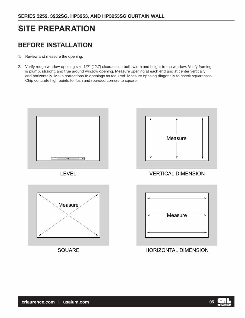
1. Review and measure the opening.
2. Verify rough window opening size 1/2" (12.7) clearance in both width and height to the window. Verify framing is plumb, straight, and true around window opening. Measure opening at each end and at center vertically and horizontally. Make corrections to openings as required. Measure opening diagonally to check squareness. Chip concrete high points to flush and rounded corners to square.
SITE PREPARATIONSERIES 3252, 3252SG, HP3253, AND HP3253SG CURTAIN WALL
ALUMINUM05crlaurence.com | usalum.com
PROFILES
NOT TO SCALE
SERIES 3252, 3252SG, HP3253, AND HP3253SG CURTAIN WALL
ALUMINUM06crlaurence.com | usalum.com
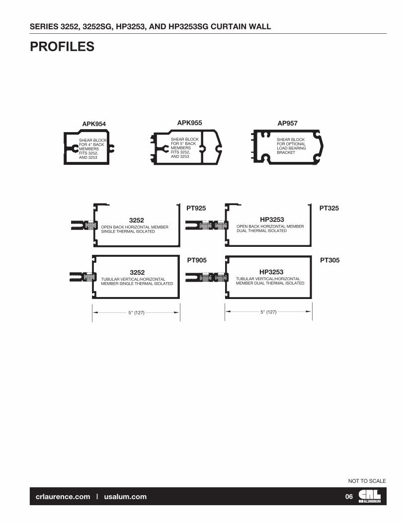
SHEAR BLOCKFOR 4" BACK MEMBERSFITS 3252, AND 3253
SHEAR BLOCKFOR 5" BACK MEMBERSFITS 3252, AND 3253
SHEAR BLOCKFOR OPTIONAL LOAD BEARING BRACKET
APK954
PT925
PT905
PT325
PT305
APK955 AP957
3252OPEN BACK HORIZONTAL MEMBERSINGLE THERMAL ISOLATED
3252TUBULAR VERTICAL/HORIZONTAL MEMBER SINGLE THERMAL ISOLATED
HP3253OPEN BACK HORIZONTAL MEMBERDUAL THERMAL ISOLATED
HP3253TUBULAR VERTICAL/HORIZONTAL MEMBER DUAL THERMAL ISOLATED
5" (127) 5" (127)

NOT TO SCALE
Most of the details shown on these instructions are for 2" (51) glazing and 5" (127) back members. Details for 1" (25) glazing systems and 5" (127) back members are similar.
FRAME FABRICATION
DETAIL A
TYPICAL ELEVATION
Rou
gh O
pen
ing
(R.O
.)
Fram
e D
imen
sion
(F.D
.)
Caulk Space Clearance
Caulk Space Clearance
2-1/2"(63.5)
2-1/2"(63.5)
2-1/2"(63.5)
2-1/2"(63.5)
D.L
.O.
D.L
.O.
D.L
.O.
D.L.O. D.L.O. D.L.O. D.L.O.
2-1/2"(63.5)
2-1/2"(63.5)
2-1/2"(63.5)
2-1/2"(63.5)
2-1/2"(63.5)Caulk Space
Clearance
Caulk Space Clearance
Frame Dimension (F.D.)
Rough Opening (R.O.)
CUTTING
1. Cut members to size. Use the following information below:
Component Dimensioning
Vertical Members: R.O. R.O. Minus Top and Bottom Clearances
Vertical Pressure Bars: F.D. Minus 1/4" (6.4)
Vertical Face Covers: F.D. Minus 1/32" (0.8)
Horizontal Members: D.L.O. Minus 1/32" (0.8) - plus 0"
Horizontal Pressure Bars: D.L.O. Minus 1/4" (6.4)
Horizontal Face Covers: D.L.O. Minus 1/32" (0.8)
Vertical Transition Adapters: D.L.O. Plus 1" (25.4)
Horizontal Transition Adapters: D.L.O. Minus 1/8" (3.2)
SERIES 3252, 3252SG, HP3253, AND HP3253SG CURTAIN WALL
ALUMINUM07crlaurence.com | usalum.com
NOT TO SCALE
FRAME FABRICATION (CONTINUED)
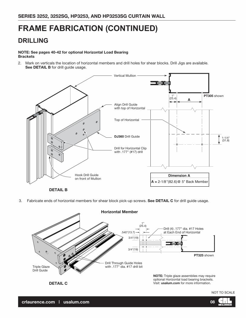
2. Mark on verticals the location of horizontal members and drill holes for shear blocks. Drill Jigs are available. See DETAIL B for drill guide usage.
DRILLING
3. Fabricate ends of horizontal members for shear block pick-up screws. See DETAIL C for drill guide usage.
DETAIL C
NOTE: See pages 40-42 for optional Horizontal Load Bearing Brackets
Horizontal Member
Drill Through Guide Holes with .177" dia. #17 drill bitTriple Glaze
Drill Guide
Drill (4) .177" dia. #17 Holes at Each End of Horizontal
1"(25.4)
3/4"(19)
3/4"(19)
.540"(13.7)
NOTE: Triple glaze assemblies may require optional Horizontal load bearing brackets. Visit: usalum.com for more information.
A
Dimension A
(82.6)
A = 2-1/8" @ 5" Back Member
DETAIL B
Vertical Mullion
Align Drill Guide with top of Horizontal
Top of Horizontal
DJ360 Drill Guide
Drill for Horizontal Clip with .177" (#17) drill
Hook Drill Guide on front of Mullion
1"(25.4)
1-1/4"(31.8)
PT305 shown
PT325 shown
SERIES 3252, 3252SG, HP3253, AND HP3253SG CURTAIN WALL
ALUMINUM08crlaurence.com | usalum.com
NOT TO SCALE
FRAME FABRICATION (CONTINUED)
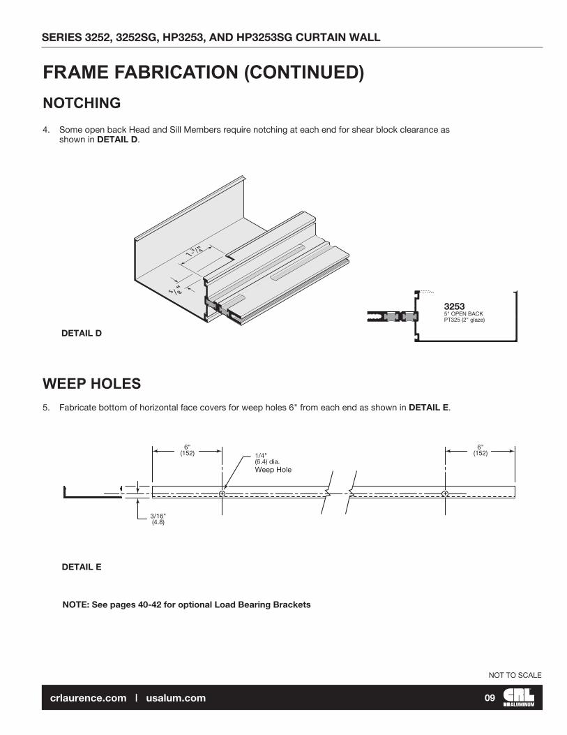
DETAIL E
DETAIL D
WEEP HOLES
4. Some open back Head and Sill Members require notching at each end for shear block clearance as shown in DETAIL D.
NOTCHING
5. Fabricate bottom of horizontal face covers for weep holes 6" from each end as shown in DETAIL E.
5⁄8"
1-³⁄4"
32535" OPEN BACK PT325 (2" glaze)
NOTE: See pages 40-42 for optional Load Bearing Brackets
6"(152)
6"(152)
3/16"(4.8)
1/4"(6.4) dia. Weep Hole
SERIES 3252, 3252SG, HP3253, AND HP3253SG CURTAIN WALL
ALUMINUM09crlaurence.com | usalum.com

6. Vertical pressure bars feature 9/32" (7.1) dia. attachment holes 9" (228.6) On Center; additional holes should be drilled at 1-1/2" (38.1) from all ends and at vertical/horizontal intersections.
7. Fabricate two 1/4" x 1-1/2" (6.4 x 38.1) weep slots 4" (101.6) from each end in horizontal pressure bars and drill 9/32" (7.1) dia. attachment holes 1-1/2" (38.1) from each end as shown on DETAIL F.
DETAIL F
PC952 PC352
FRAME FABRICATION (CONTINUED)
Jamb(Right shown)
IntermediateVertical
of HorizontalC L
1/8"(3�2)
1-1/2"(38�1)
9" O�C�(228�6)
3"(76�2)
9" O�C�(228�6)
9/32 (7�1)"Dia� holes (Typ�)
1-1/2"(38�1)
1/8"(3�2)
Fram
e D
imen
sion
4"(101�6)
1/8"(3�2)
1-1/2"(38�1)
1-1/2"(38�1)Typ�
9" O�C�(228�6)
1/4" (6�4)1-1/2"(38�1)
1-1/2"(38�1)
1/8""(3�2)
9/32" (7�1)Dia� holes (Typ�)
IntermediateHorizontal
Sill
Head
Line of D�L�O� Line of D�L�O�
PERIMETER PRESSURE BARS
Series 3252 Series 3253
1" Glass 2" Glass
NOT TO SCALE
SERIES 3252, 3252SG, HP3253, AND HP3253SG CURTAIN WALL
ALUMINUM10crlaurence.com | usalum.com

NOTE: ANCHOR TYPE AND SIZES VARY PER JOB REQUIREMENTS. DETAILS SHOWN ARE TO BE USED AS A GUIDE ONLY. SEE APPROVED SHOP DRAWINGS FOR ACTUAL CONDITIONS.
1. Slide top and bottom "T" anchors into vertical members. See DETAIL G.
2. Install verticals plumb and level. If shims are required place them directly under each vertical for proper load distribution. Secure top and bottom anchors to structure.
SINGLE SPAN CONDITION
FRAME INSTALLATION
DETAIL G
"T" Anchors at Wall Jamb Condition (Two Bolts Minimum)Typical at Top and Bottom
Top and Bottom "T" Anchors
Shim Both Sides
Field Prepare per Job Conditions and Loading. Two Bolts at each Anchor Minimum.
Closer Plates Shown for Reference. See DETAIL N for Closer Plate Installation.
Aluminum anchors must be Isolated from dissimilar materials� Typical at
top and bottom�
NOT TO SCALE
SERIES 3252, 3252SG, HP3253, AND HP3253SG CURTAIN WALL
ALUMINUM11crlaurence.com | usalum.com

DETAIL H
3. Attach shear blocks to verticals with screws provided. See DETAIL H for shear blocks position. NOTE: Use tubular horizontals when span exceeds 6'-0" (1.8 m) or deadload exceeds 250 lbs. (113.4 Kg) use optional load bearing bracket and proper horizontal mullion when glazing unit exceeds deadload chart. (See page 40)
5" (127) HORIZONTALS
FRAME INSTALLATION (CONTINUED)
(2) ST269 #12 x 2" PH Phillips
Shear Block Position for Header
Shear Block Position for Intermediate Horizontal.
Shear Block Position for Intermediate Sill
Use APK954 for 4" (101.6) Members APK955 for 5" (127) Members
(2) ST269 #12 x 2" PH Phillips
Use APK954 for 4" (101.6) Members APK955 for 5" (127) Members
3252
3253
SINGLE SPAN CONDITION (CONTINUED)4" (101.6) HORIZONTALS
NOT TO SCALE
SERIES 3252, 3252SG, HP3253, AND HP3253SG CURTAIN WALL
ALUMINUM12crlaurence.com | usalum.com
SINGLE SPAN CONDITION (continued)
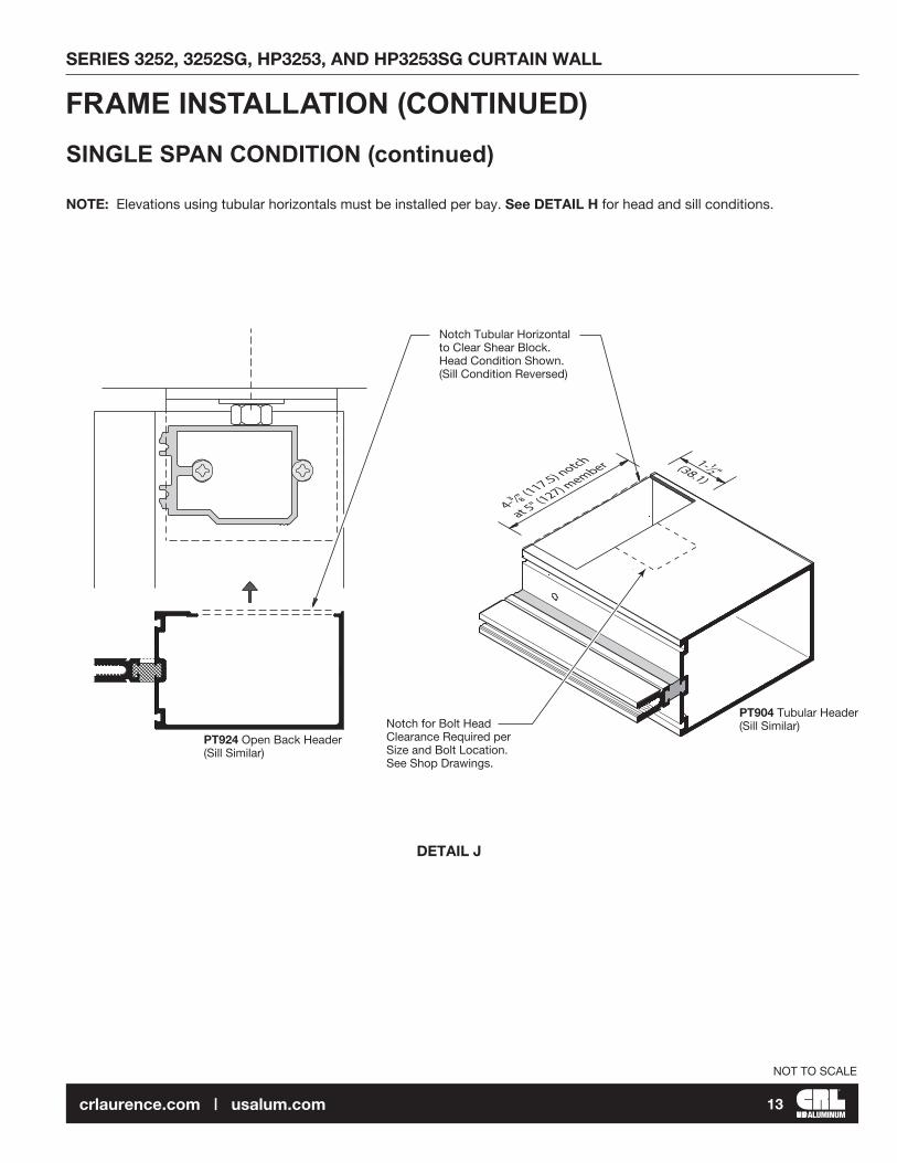
NOTE: Elevations using tubular horizontals must be installed per bay. See DETAIL H for head and sill conditions.
DETAIL J
FRAME INSTALLATION (CONTINUED)
4-³⁄8" (1
17.5) notch
at 5" (127) m
ember 1-¹⁄2" (38.1)
Notch Tubular Horizontal to Clear Shear Block. Head Condition Shown. (Sill Condition Reversed)
Notch for Bolt Head Clearance Required per Size and Bolt Location. See Shop Drawings.
PT924 Open Back Header (Sill Similar)
PT904 Tubular Header (Sill Similar)
NOT TO SCALE
SERIES 3252, 3252SG, HP3253, AND HP3253SG CURTAIN WALL
ALUMINUM13crlaurence.com | usalum.com

MULTI-SPAN CONDITION
Details K and L show fixed (deadload) and expansion (windload) anchors. Anchor type and size vary per job requirements. Details shown are to be used as a guide only. See approved shop drawings for actual conditions.
1-1/2” min.
(38.1)
1-1/2” min.
(38.1)
4. Secure verticals to anchor clips after alignment has been completed.
NOTE: Mullion spacing must be held to within +1/32" (0.8). Check overall frame dimension every four bays to monitor dimension build up.
Fixed anchor(Deadload anchor)
Expansion anchor(Windload anchor)
Drill Holes after alignment has been completed.
AP360 Nylatron Pad
Primary Bolts with Nuts Flat Washer and Lock Washer
DETAIL K
Drill Holes after alignment has been completed.
AP360 Nylatron Pad
Primary bolts with nuts, flat washer and lock washer. Back off nut 1/4" turn after tightening to allow for thermal movement.
DETAIL L
3253 shown, 3252 similar
FRAME INSTALLATION (CONTINUED)
NOT TO SCALE
SERIES 3252, 3252SG, HP3253, AND HP3253SG CURTAIN WALL
ALUMINUM14crlaurence.com | usalum.com

MULTI-SPAN CONDITION (continued)
TWO PIECE HORIZONTALS
5. Roll horizontal members over shear blocks and secure them with screws provided. See DETAIL M.
NOTE: See pages 40-42 for optional Load Bearing Brackets.
DETAIL M
Secure Horizontal Members to Shear Blocks with (2) ST19300 #8 x 3/4" PH Phillips
NOTE: Top and Intermediate Horizontals must be Installed with Open Side Up
NOTE: Sill Members must be Installed with Open Side Down
NOTE: Open Side Up
NOTE: Open Side Down
1/2" (12.7) Minimum
FRAME INSTALLATION (CONTINUED)
NOT TO SCALE
SERIES 3252, 3252SG, HP3253, AND HP3253SG CURTAIN WALL
ALUMINUM15crlaurence.com | usalum.com

MULTI-SPAN CONDITION (continued)
Install snap-in horizontal filler where open back of horizontal member is exposed.NOTE: Snap-in fillers are optional at head and sill to facilitate interior caulking. (Cut fillers short to clear shear blocks and snap them in before installing)
DETAIL N
6. Slide horizontals over shear blocks and secure them with screws provided. See DETAIL N.
TUBULAR HORIZONTALS
7. Apply RTV408 Silicone sealant to closer plates as shown in DETAIL O. Install at top and bottom of jambs and mullions after head and Sill Members are in place.
DETAIL O
NOTE: It May Be Necessary to also attach Horizontal to Shear Block through Top or Bottom to Keep Tight Joint at Rear. See DETAIL N
(2) ST19300 #8 x 3/4" PH Phillips
Insert Closer Plate into Vertical Screw Race Apply RTV408 Silicone
Sealant to Surface at Contact Area
Head and Sill not shown
NOTE: Clean All Surfaces prior to Applying Sealants. See Sealant Manufacturer Requirements.TYPICAL AT ALL CONDITIONS
Position closer plate properly. Raised letters "EXTERIOR"
FRAME INSTALLATION (CONTINUED)
NOT TO SCALE
SERIES 3252, 3252SG, HP3253, AND HP3253SG CURTAIN WALL
ALUMINUM16crlaurence.com | usalum.com

8. Once all verticals and perimeter members are installed, apply Cat. No. 95C/M64/M66 Sealant to seal around perimeter. Perimeter caulking must be completed prior to installation of glass and pressure bars. Insure perimeter sealant has smooth transition across vertical end dams.
DETAIL P
9. Apply RTV408 Silicone Sealant to seal joint between horizontal and vertical. Also seal over heads of screws in the glazing pockets with Cat. No. 33S Silicone.
10. Apply RTV408 Silicone Sealant at the three contact areas of end dams. Also fill the vertical gasket reglet with RTV408 Silicone Sealant at the end dam location. See DETAIL P. Slide end dams into place. NOTE: End dams occur at head and sill also.
DETAIL Q
NOTE: See pages 40-42 for optional Horizontal Load Bearing Brackets
CRITICAL SEAL Seal horizontal/vertical joint intersection with RTV408 Silicone Sealant
CRITICAL SEAL Seal over head of screws with Cat. No. 33S Silicone
CRITICAL SEAL Fill the Vertical Gasket Reglet with RTV408 Silicone Sealant behind the End Dam
CRITICAL SEAL Apply RTV408 Silicone Sealant to the three Contact Areas
End Dam HD885 for 3253 2" glazing system
NOTE: Consult sealant manufacturer for proper cleaning and priming recommendations
Cat No. 95C/M64/M66 Sealant Perimeter Caulking
1" (25) Glazing System
FRAME INSTALLATION (CONTINUED)MULTI-SPAN CONDITION (continued)
NOT TO SCALE
SERIES 3252, 3252SG, HP3253, AND HP3253SG CURTAIN WALL
ALUMINUM17crlaurence.com | usalum.com

GLASS WIDTH & HEIGHT = DAYLIGHT OPENING + 1" (25.4)
NOTE: These formulae do not take into account glass tolerances. Consult glass manufacturer before ordering glass.
Remove gaskets from carton and lay flat in a clean, dry area in order to recover shape. Allow gaskets to relax at least two hours at temperatures above 50°F (10°C). Glaze with gaskets above 40°F (4.44°C). If necessary warm gaskets in a hot box prior to installing.
Use NP430 dense gasket at exterior and NP420 sponge at interior.
1. Cut gaskets allowing 1/8" (3.2) extra length per foot of extrusion to allow for shrinkage. Vertical gaskets on mullion run past horizontal gaskets by 5/8" (15.9). See DETAIL R Horizontal gaskets butt against vertical gaskets.
2. Install back gaskets into vertical and horizontal members and front gaskets into pressure bars. Horizontal pressure bar gaskets should extend 1/8" (3.2) beyond each end of the extrusions. Vertical pressure bar gaskets run continuous.
3. Position two setting blocks for each glass lite as directed by the deadload charts and shop drawings.
4. Peel off side blocks paper backing and locate them, two per glass lite, at approximately mid-height of glass. See DETAIL R.
DETAIL R
GLASS SIZES
GLAZING
of glass
Peel off Back-Up paper and stick Block to Vertical at glass mid point.
Two Side Blocks per Glass Lite. NOTE: Due to glass tolerances Side Blocks may be installed after glass.
Side Block (Anti-Walk Block)
Setting Blocks Two per Glass Lite
NOT TO SCALE
SERIES 3252, 3252SG, HP3253, AND HP3253SG CURTAIN WALL
ALUMINUM18crlaurence.com | usalum.com

5. Apply bead of sealant at interior gaskets' corners 2" (50.8) in each direction. See DETAIL T.
6. Install glass and center in opening. Use CW368 temporary glass retainers to hold glass in place until pressure bars are installed. See DETAIL S.
DETAIL S
7. Apply sealant to face of dams. This is a critical seal area. See DETAIL T.
Shown after glazingShown before glazing
CRITICAL SEAL AREAApply Sealant to face of End Dams right before installing Pressure Bars.
NOTE:Vertical Gaskets do not run through to allow for End Dam installation.They extend approximately 5/8” (16)past the edge of the Horizontal.
CL
5/8” (16)
2”(50.8)
2”(50.8)
Apply Sealant to Interior Gasketscorner 2” (50.8) in each direction
DETAIL T
GLAZING (CONTINUED)
CW368 Temporary Glass Retainer. Torque to 30 in.-lbs. (3.4N.m) NOTE: Do not over torque Glass Retainer bolts. Use one Retainer per each 150 lbs. (667.2N) of load (i.e. if Glass Height x Glass Width x Windload = 350 lbs. use three Retainers each side of glass).
NOT TO SCALE
SERIES 3252, 3252SG, HP3253, AND HP3253SG CURTAIN WALL
ALUMINUM19crlaurence.com | usalum.com

STRUCTURAL SILICONE GLAZING VERTICAL MULLIONSSeries HP3253SG Triple glaze is shown below, Series 3252SG dual glaze is similar.
1
2
3
4 5 5
GLASS WIDTH & HEIGHT = DAYLIGHT OPENING + 1" (25.4)NOTE: These formulae do not take into account glass tolerances. Consult glass manufacturer before ordering glass.
Remove gaskets from carton and lay flat in a clean, dry area in order to recover shape. Allow gaskets to relax at least two hours at temperatures above 50°F (10°C). Glaze with gaskets above 40°F (4.44°C). If necessary warm gaskets in a hot box prior to installing.
For the intermediate horizontal mullions, use NP430 dense gasket at the exterior and NP420 sponge gasket for the interior. Use SP450 spacer gasket on the Intermediate Vertical Mullions.
1. Cut gaskets 1/8" (3.2) long per foot of extrusion to allow for shrinkage. Vertical gaskets on mullion run past horizontal gaskets by 5/8" (15.9). See DETAIL W. Horizontal gaskets butt against vertical gaskets. Insert a water deflector between the two horizontal members and install spacer gaskets into verticals. See DETAIL U.
Insert SP450 Spacer Gaskets into the Vertical Mullion
Insert Water Deflector between Horizontals
SP450 Spacer Gaskets
1
2
3
4 5 5
2
Typical Elevation
PT305 CW935 CW935
SP450 SP450NP420
NP430
PC352 CW901
PT325
PT325
PT325
AP955
AP955
AP955
CW901
PC352
CW901
PC352
CW901
CW933
SB933
NP420NP430
DETAIL U
Refer to item 8 of the General Installation Notes on page 03 regarding structural sealants.
NOT TO SCALE
SERIES 3252, 3252SG, HP3253, AND HP3253SG CURTAIN WALL
ALUMINUM20crlaurence.com | usalum.com
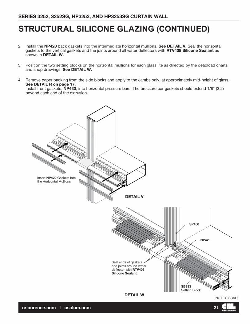
2. Install the NP420 back gaskets into the intermediate horizontal mullions. See DETAIL V. Seal the horizontal gaskets to the vertical gaskets and the joints around all water deflectors with RTV408 Silicone Sealant as shown in DETAIL W.
3. Position the two setting blocks on the horizontal mullions for each glass lite as directed by the deadload charts and shop drawings. See DETAIL W.
4. Remove paper backing from the side blocks and apply to the Jambs only, at approximately mid-height of glass. See DETAIL R on page 17. Install front gaskets, NP430, into horizontal pressure bars. The pressure bar gaskets should extend 1/8" (3.2) beyond each end of the extrusion.
Insert NP420 Gaskets into the Horizontal Mullions
Seal ends of gaskets and joints around water deflector with RTV408 Silicone Sealant.
SB933 Setting Block
DETAIL V
DETAIL W
SP450
NP420
STRUCTURAL SILICONE GLAZING (CONTINUED)
NOT TO SCALE
SERIES 3252, 3252SG, HP3253, AND HP3253SG CURTAIN WALL
ALUMINUM21crlaurence.com | usalum.com
DETAIL X
DETAIL Y
Horizontal Pressure Bar
RG720 2" Glass retainer
1-1/2" (38.1)
1-1/2" (38.1)
Weep slot
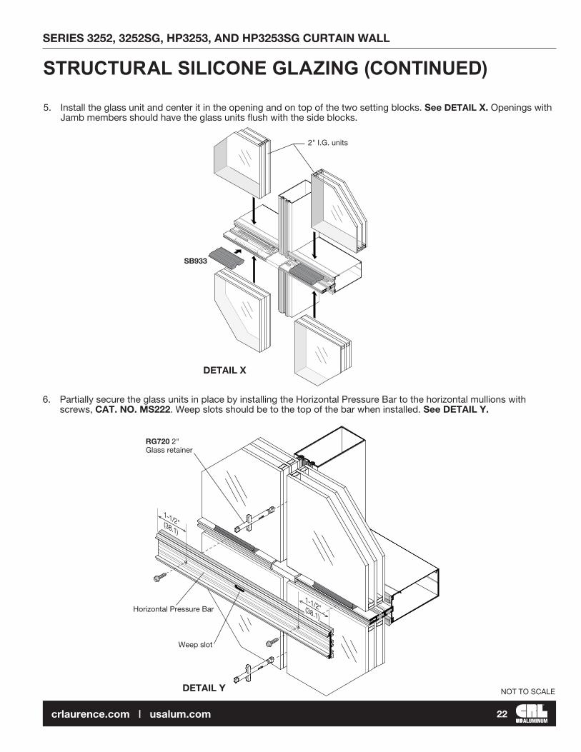
5. Install the glass unit and center it in the opening and on top of the two setting blocks. See DETAIL X. Openings with Jamb members should have the glass units flush with the side blocks.
STRUCTURAL SILICONE GLAZING (CONTINUED)
6. Partially secure the glass units in place by installing the Horizontal Pressure Bar to the horizontal mullions with screws, CAT. NO. MS222. Weep slots should be to the top of the bar when installed. See DETAIL Y.
SB933
2" I.G. units
NOT TO SCALE
SERIES 3252, 3252SG, HP3253, AND HP3253SG CURTAIN WALL
ALUMINUM22crlaurence.com | usalum.com

7. At the Intermediate Verticals, install RG720 temporary glass retainers. (See DETAIL AA for number of clips per mullion). Insert the long end of the retainer in between the glass units and turn clockwise to engage with the mullion. See DETAIL Z.
DETAIL Z
Turn clockwise to lock
RG720 Temporary glass retainer
DETAIL AA
WIDTH OF SPAN
LOWER PRESSURE BAR
UPPER PRESSURE BAR
TEMPORARYGLASSRETAININGCLIP
NUMBER OFCLIPS 150
=
(ft)
WIDTH OF SPAN X HEIGHT OF SPAN X WINDLOAD (psf)
HEIGHT OF
SPAN (ft)
STRUCTURAL SILICONE GLAZING (CONTINUED)
NOT TO SCALE
SERIES 3252, 3252SG, HP3253, AND HP3253SG CURTAIN WALL
ALUMINUM23crlaurence.com | usalum.com

DETAIL BB DETAIL CC
DETAIL DD
8. Securing the glass from the exterior with the horizontal pressure bars and temporary retainers. See DETAIL BB. Apply structural silicone to the intermediate vertical mullions on the interior side.
The gap between the intermediate vertical mullion and the glass will be filled with structural silicone. Use masking tape along the edge of the mullion and on the glass to achieve a clean bead after tooling. See DETAIL CC. Remove the masking tape before the silicone cures.
NOTE: Always follow structural silicone manufacturer's instructions and recommendations for surface preparation and silicone application.
9. Following the manufacturer's specifications, allow the silicone to fully cure before removing the temporary glass retainers. After removing the glass retainers, insert open cell polyurethane backer rod between the glass edges on the exterior side. Mask glass and aluminum adjacent to joint and apply CRL RTV408 sealant for an exterior weatherseal. See DETAIL DD.
Insert backer rod
Masking tape and sealant
Tooled weatherseal
Tool sealant
STRUCTURAL SILICONE GLAZING (CONTINUED)
NOT TO SCALE
SERIES 3252, 3252SG, HP3253, AND HP3253SG CURTAIN WALL
ALUMINUM24crlaurence.com | usalum.com

DETAIL EE
DETAIL FF
10. Install the horizontal face cover onto the pressure bar, see DETAIL EE. Locate splice joints at center line of vertical glass butt joints. Splice joint width should be based on formula for linear expansion for aluminum specifications and sealant movement capability. NOTE: Do not align face cover splices with pressure bar splices. Offset 6" (152.4) minimum. See DETAIL FF. Set backer rod between face cover and pressure bar at joint and seal.
Tool sealant over backer rod
Install Face Cover CW901
Apply bond breaker tape to face of splice sleeve and seal over splice joint with Cat. No. 95C Silicone
6" (152.4)Minimum offset
1-1/2" (38.1) 1-1/2" (38.1)
Weatherseal
Weep slot
CW901
STRUCTURAL SILICONE GLAZING (CONTINUED)
HORIZONTAL FACE COVER SPLICE JOINTS
NOT TO SCALE
SERIES 3252, 3252SG, HP3253, AND HP3253SG CURTAIN WALL
ALUMINUM25crlaurence.com | usalum.com

Install vertical pressure bar bolts from bottom to top and horizontal pressure bar bolts from center outward.Always locate bolts 1-1/2" (38.1) maximum from vertical/horizontal intersections to ensure proper pressure over end dams. See DETAIL S. Be sure pressure bar spacer is not disengaged.
1. Install vertical pressure bars first leaving 1/8" (3.2) gaps at top and bottom. Using a speed wrench, torque bolts to 30 inch pound (3.4N.m). Increase torque to 50 to 60 inch pound (5.7 to 6.8 N.m) minimum after all four sides have been secured.
2. Center horizontal pressure bars in opening leaving 1/8" (3.2) gaps at each end. NOTE: weep slots must be in top side of all horizontal pressure bars and level with bottom of glazing pocket to ensure proper drainage. See DETAIL T. 3. Seal gaps at vertical/horizontal intersections and at top and bottom of vertical pressure bars. See DETAIL U.
4” (101.6)
(228
.6)
9” O
.C.
Typ
ical
3”(76.2)
1/8” (3.2) gap
1-1/2”(38.1)
1-1/2”(38.1)
1/8” (3.2) gap
1/2”(38.1)
DETAIL U
PRESSURE BAR INSTALLATION
NOTE: Weep slots are required in all Horizontal Pressure Bars Including the Head or Top Horizontal
Pressure Bar Typical
Seal All Gaps and Tool Sealant Making Sure it Will Not Interfere with the Snap on Face Cover (Typ.)
Weep slots should be at top side of all pressure bars.
NOT TO SCALE
SERIES 3252, 3252SG, HP3253, AND HP3253SG CURTAIN WALL
ALUMINUM26crlaurence.com | usalum.com

Care must be taken to prevent damage of face covers during installation. Use a piece of wood such as 2" x 4" x 12" (51 x 102 x 305) and a 3" (76.2) diameter Stanley 3 lbs. (13.3N) Compo-Cast dead blow soft face hammer.
4. Install vertical face covers first. Do not disturb top and bottom closure plates when installing face covers. Pinning of vertical face cover is required to prevent slippage. Use one pin on each side per cut length, concealed behind horizontal face cover closer to center line or as shown on shop drawings. See DETAIL U.
5. Install snap-in horizontal face covers with the weep holes located on the bottom side. Seal gaps at vertical/horizontal intersections and at top and bottom of vertical pressure bars. See page 8 DETAIL E.
NOTE: Extended face covers require a special pressure bar. Pin vertical extended covers with one 1/8" (3.2) dia. pop rivet on each side per cut length (optional #10 x 1/2" FH SMS) See DETAIL V. Extended horizontal covers must be pinned on top side at both ends.
FACE COVER INSTALLATION
DETAIL V DETAIL W
1/16" x 1/2" (1.6 x 12.7) roll pin at center of cut length on each side. (Concealed behind horizontal face cover)
1/8" (3.2) pop rivet at center of cut length at each side. (Concealed behind horizontal face cover)
NOT TO SCALE
SERIES 3252, 3252SG, HP3253, AND HP3253SG CURTAIN WALL
ALUMINUM27crlaurence.com | usalum.com

1. Apply sealant into gasket reglets before installing snap-in transition adaptors.
2. Install vertical adaptors first.
3. Install horizontal adaptors and seal horizontal/vertical joints. Tool sealant. See DETAIL X.
PC921From 1" to 1/4 " Glassfor Series 3252
PC321From 2" to 1/4 " Glass for Series 3253
Horizontal Adaptors
Seal Horizontal/ Vertical Joint and Tool Sealant.
Vertical Adaptor Runs ThroughNOTE: Discontinue Vertical Adaptors at Splice Joints
Fill Gap Between Adaptors and Main Members at All Sides of Opening with Continuous Bead of Sealant.
Fill Gasket Reglet with Sealant before Installing Adaptors (This is a Continuous Seal)
D.L.O.
D.L.O. -1/8" (3.2)
D.L
.O.
D.L
.O. +
1" (2
5.4)
TRANSITION GLAZING
DETAIL X
NOTE: See Pages 40-42 for optional Load Barring Brackets
NOT TO SCALE
SERIES 3252, 3252SG, HP3253, AND HP3253SG CURTAIN WALL
ALUMINUM28crlaurence.com | usalum.com

Splice joint width should be based on sealant movement capability and on the following formula:
A 1/2" (12.7) minimum joint is recommended. Use a 1/2" (12.7) spacer shim to set and hold the mullion joint constant during erection. Remove the shim after attaching the verticals to the anchors. Splice joints must occur at spandrel areas.
1. Clean splice sleeves and all joint surfaces. Apply bond breaker tape at areas where sleeve will be sealed to avoid three side adhesion. See DETAIL Y.
2. Slide sleeve into the upper member before it is installed and tape to hold it in retracted position. See DETAIL Y.
DETAIL Y
3. Install stop screw, 2-3/4" (70) down from top of extrusion at inside of lower member. See DETAIL Z.
4. Install upper member and let extruded sleeve slide down until it sits on top of stop screw.
5. Seal joint over sleeve as shown in DETAIL AA. When transition adaptors for 1/4" (6) spandrel are used they should be discontinued at splice joint and installed after splice joint is sealed. Stagger joints on back members, pressure bars and face caps as shown in DETAIL Z.
6. Seal pressure bar joint. See DETAIL AA.
7. Install face covers and seal joint using backer rod as required. See DETAIL Z.
VERTICAL SPLICE JOINTS
Linear expansion for aluminum, in inches = Length (") x F° difference in temperature x .0000129 Linear expansion for aluminum, in millimeters = Length (m) x C° difference in temperature x .02322
Splice Sleeve
Tape to Hold Sleeve in Retracted Position
Apply Bond Breaker Tape to Sleeve at Joint Area
NOT TO SCALE
SERIES 3252, 3252SG, HP3253, AND HP3253SG CURTAIN WALL
ALUMINUM29crlaurence.com | usalum.com

1
DETAIL Z
DETAIL AA
VERTICAL SPLICE JOINTSSplice Sleeve
Use backer rod to facilitate face cover seal
Bond Breaker
Tape
Seal and Tool Joint
Seal Pressure Bar Joint
Seal Face Cover joint and Tool (Use Backer
Rods as required)
2-3/4"(70)
1-1/2"(38.1)
1-1/2"(38.1)
1"(25.4)
1/2"(12.7) min. Splice Joint Width
4"(101.6)
1/2"(12.7) Face Cover Splice Joint
1/2"(12.7) Pressure Bar Splice
Stop Screw
Bond Breaker Tape
NOT TO SCALE
SERIES 3252, 3252SG, HP3253, AND HP3253SG CURTAIN WALL
ALUMINUM30crlaurence.com | usalum.com

Shim at fastener locations
TT461Thermal Door Jamb
TT461 Thermal Door Jamb
TT245 Threshold for Offset Hung Door
Trim Closure Plate at Door Jamb side to clear door frame
Trim Closure Plate at Door Jamb side to clear door frame
DS051Snap-In Door Stop for Offset Hung Door
NOTE: For Entrance Frames installation see ENTRANCES, of this manual
DS051Snap-In Door Stop for Offset Hung Door
TT245 Threshold for Offset Hung Door
Attach Door Jamb to Vertical
24” (609.6) O.C.with #10 x 3/4” P.H.S.M.S.
Seal pocket of door subframeup to top of threshold
Attach Door Jamb to Vertical
24” (609.6) O.C.with #10 x 3/4” P.H.S.M.S.
Continuous exteriorperimeter seal
PT905
PT325
PT325
HD885 End Dam
Shim at fastener locations
Seal pocket of door subframeup to top of threshold with Cat. No. 95C Silicone.
HD975 End Dam
NOTE: Sealant between Thermal Door Jamb TT461 and Pocket Filler PC952 must mate with exterior perimeter seal.
PC952 Pocket Filler
PC952 Pocket Filler
PT905
Entrance Frames may be installed simultaneously with Curtain Wall or after Curtain Wall installation has been completed. Use PC952 or PC352 pocket fillers to close glazing pocket at door side.
ENTRANCE FRAMES
DETAIL BB
SERIES 3252
Offset Hung Door
DETAIL CC
SERIES HP3253
Offset Hung Door
NOT TO SCALE
SERIES 3252, 3252SG, HP3253, AND HP3253SG CURTAIN WALL
ALUMINUM31crlaurence.com | usalum.com

FLUSH DOOR ADAPTER - FABRICATION
DETAIL DD
1. Cut Door adaptor members to length.
2. Drill 5/8" (7.9) diameter anchor holes in all cut to length adaptors 1-1/2" (38.1) from each end and 9" (228.6) O.C. See DETAIL DD. NOTE: Isolator must be in place prior to drilling anchor holes.
Header adapter length = DOOR OPENING WIDTH minus 1/32" (.8)
Jamb adapter length = DOOR OPENING HEIGHT plus 9/16" (14)
CW907
Header cap length = DOOR OPENING WIDTH minus 1/32" (.8)
Jamb cap length = DOOR OPENING HEIGHT plus 9/16" (14)
CW906
Header door stop length = DOOR OPENING WIDTH minus 1/32" (.8)
Jamb door stop length = DOOR OPENING HEIGHT plus 1-3/32" (27.8)
CW209
1-1/2"(38.1)
1-1/2"(38.1)
5/16" (7.9) Dia. Holes
CW907
Isolator
Holes centered on groove
9" O.C. (Typ.)
(228.6)
NOT TO SCALE
SERIES 3252, 3252SG, HP3253, AND HP3253SG CURTAIN WALL
ALUMINUM32crlaurence.com | usalum.com

ANCHOR HOLEWEEP SLOTS
DOOR OPENING WIDTH minus 1/32"
WEEP SLOTS
DOOR OPENING WIDTH minus 1/32"
CL
CL
ANCHOR HOLE
FLUSH DOOR ADAPTER - FABRICATION
DETAIL FF
DETAIL GG
3. Fabricate header adaptor for weep slots and additional anchor holes as shown in DETAIL EE.
4. For offset pivot doors, fabricate header adaptor for pivot (left hand shown), weep slots and additional anchor holes as shown in DETAIL FF. Notch face cap for pivot clearance as shown in DETAIL GG.
DETAIL EE
1-1/2"(38.1)
1-1/2"(38.1)
4"(101.6)
4"(101.6)
1-1/2"(38.1)
1-1/2"(38.1)
4"(101.6)
4"(101.6)
1-1/2"(38.1)
1-1/2"(38.1)
1-1/2"(38.1)
1-1/2"(38.1)
CW907
CW907
9" O.C. (228.6)
9" O.C. (228.6)
CW906
1-3/16"(30.2)
1/4"(6.4)
1/16"(1.6)
11/64" (4.4) Dia. Hole or #16 Drill Bit
Drill & Csk. for1/4"-20 FH MS
1-5/32"(29.4)
5/8"(15.9)
15/32"(11.9)
27/32"(21.4)
3/16"(4.8)
3/16"(4.8)
11/64" (4.4) Dia. Hole or #16 Drill Bit
NOT TO SCALE
SERIES 3252, 3252SG, HP3253, AND HP3253SG CURTAIN WALL
ALUMINUM33crlaurence.com | usalum.com
DETAIL HH DETAIL II
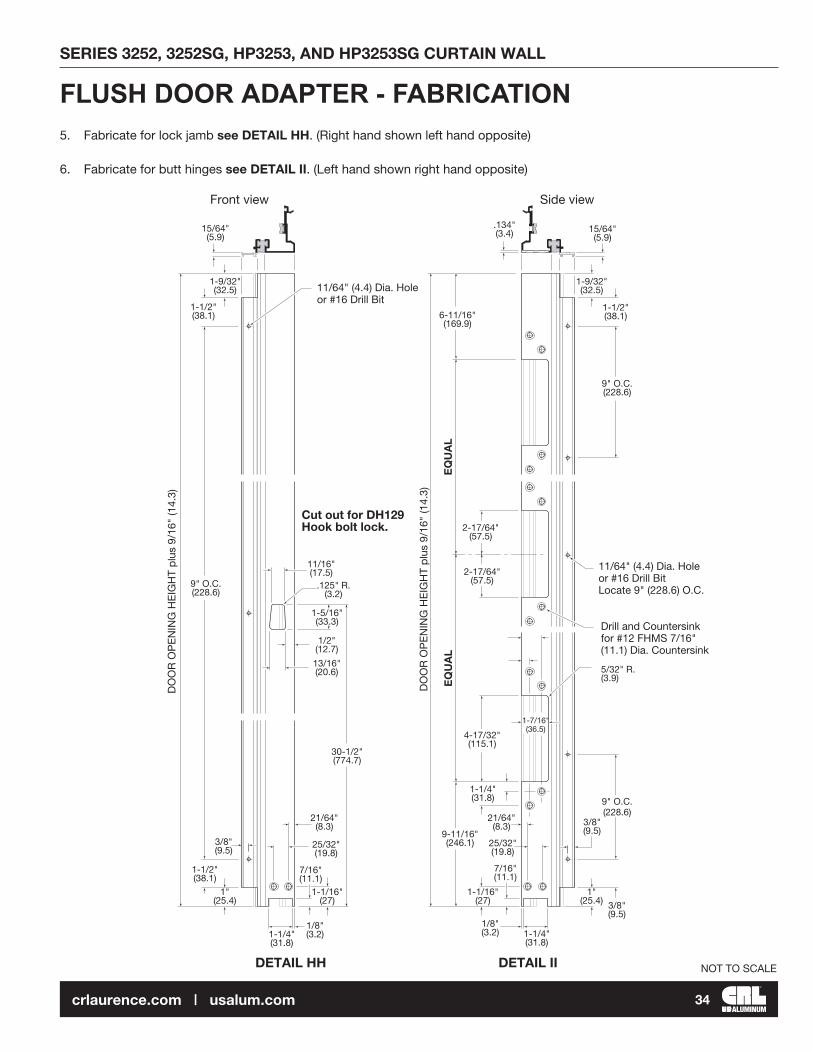
FLUSH DOOR ADAPTER - FABRICATION 5. Fabricate for lock jamb see DETAIL HH. (Right hand shown left hand opposite)
6. Fabricate for butt hinges see DETAIL II. (Left hand shown right hand opposite)
Front view Side view
15/64"(5.9)
1-9/32"(32.5)
1-1/2"(38.1)
11/16"(17.5)
.125" R.(3.2)
1-5/16"(33.3)
1/2"(12.7)
13/16"(20.6)
30-1/2"(774.7)
21/64"(8.3)
25/32"(19.8)
7/16"(11.1)
1-1/16"(27)
1/8"(3.2)1-1/4"
(31.8)
3/8"(9.5)
1-1/2"(38.1)
1"(25.4)
DO
OR
OP
EN
ING
HE
IGH
T p
lus
9/16
" (1
4.3)
9" O.C. (228.6)
EQ
UA
LE
QU
AL
.134"(3.4) 15/64"
(5.9)
1-9/32"(32.5)
1-1/2"(38.1)
9" O.C. (228.6)
6-11/16"(169.9)
11/64" (4.4) Dia. Hole or #16 Drill Bit Locate 9" (228.6) O.C.
Drill and Countersink for #12 FHMS 7/16" (11.1) Dia. Countersink
5/32" R. (3.9)
DO
OR
OP
EN
ING
HE
IGH
T p
lus
9/16
" (1
4.3)
9" O.C. (228.6)
3/8"(9.5)
1"(25.4)
1-1/4"(31.8)
1/8"(3.2)
7/16"(11.1)
1-1/16"(27)
4-17/32"(115.1)
9-11/16"(246.1) 25/32"
(19.8)
21/64"(8.3)
1-1/4"(31.8)
3/8"(9.5)
1-7/16"(36.5)
2-17/64"(57.5)
2-17/64"(57.5)
11/64" (4.4) Dia. Hole or #16 Drill Bit
Cut out for DH129 Hook bolt lock.
NOT TO SCALE
SERIES 3252, 3252SG, HP3253, AND HP3253SG CURTAIN WALL
ALUMINUM34crlaurence.com | usalum.com

CL
DETAIL JJ
FLUSH DOOR ADAPTER - FABRICATION
9/16"(14.3)
15/64"(5.9)
15/64"(5.9)
1-3/8"(34.9)
1-1/2"(38.1)
1"(25.4)
1/2"(12.7)
25/32"(19.8) 3/8"
(9.5)
21/64"(8.3)
25/32"(19.8)
1-1/16"(27)
7/16"(11.1)
1/8"(3.2)
1-1/4"(31.8)
1"(25.4)
1-1/2"(38.1)
11/32"(8.7)
1-9/16"(39.7)
9" O.C. (228.6)11/64" (4.4) Dia.Hole
or #16 Drill Bit
3/8"(9.5)
Drill and Countersink for 1/4"-20 F.H.M.S.
Doo
r O
pen
ing
÷ 2
DO
OR
OP
EN
ING
HE
IGH
T p
lus
9/16
" (1
4.3)
Top of Door Opening
(Reference)
Top of Cut-out
3/8"(9.5)
Drill and Countersink for #12 F.H.M.S. 7/16" (11.1) Dia. Countersink
Bottom of Door Opening (Reference)
NOT TO SCALE
SERIES 3252, 3252SG, HP3253, AND HP3253SG CURTAIN WALL
ALUMINUM35crlaurence.com | usalum.com

BP45900Backup Plate
MS172 (4)#12-24 x 1/2"
(2) MS172#12-24 x 1/2"
0P400Frame Portion Bottom Pivot(Supplied with Door Hardware)
(2) MS172#12-24 x 1/2"
TC50000Anchor clip(Supplied with Door Hardware)
FLUSH DOOR ADAPTER - FABRICATION
DETAIL KK DETAIL LL DETAIL MM
7. For butt hung application, install hinge back up plates and threshold clips as shown in DETAIL KK and DETAIL LL. For offset pivot application, install bottom frame portion pivot(s) as shown in DETAIL MM. Single doors require threshold clip at lock jamb. See DETAIL LL.8. Install gaskets in door adaptors.
These hardware items must be applied prior to door adaptor installation.
NOT TO SCALE
SERIES 3252, 3252SG, HP3253, AND HP3253SG CURTAIN WALL
ALUMINUM36crlaurence.com | usalum.com

FLUSH DOOR ADAPTER - INSTALLATIONNOTE: PRIOR TO ADAPTOR INSTALLATION ALL END DAMS MUST BE INSTALLED AND SEALED. TRANSOM AND SIDELIGHT GLASS MUST BE IN PLACE.
1. Seal face of end dams DETAIL S.
2. Install jamb door adaptors using MS22200 pressure bar bolts as shown in DETAIL NN. Vertical adaptors extend from floor to 9/16" above bottom of door header/horizontal. Install head door adaptor using MS22200 pressure bar bolts as shown in DETAIL NN.
3. Secure adaptors to mullion and head side walls with 20081601 self-drilling screws as shown in DETAIL NN.
4. Seal all pressure bar bolt heads. See DETAIL OO.
5. Seal gaps at intersections of pressure bars and door adaptors.
DETAIL NN
DETAIL OO
NOTE: This is a critical seal
Seal Pressure Bar Bolt Heads
Seal Intersecting Pressure Bar and Adapters Joints
200816018-18 x 1/2" P.H. Phillips self-drilling screw
MS22200 Pressure bar screw
NOT TO SCALE
SERIES 3252, 3252SG, HP3253, AND HP3253SG CURTAIN WALL
ALUMINUM37crlaurence.com | usalum.com

6. Install thresholds into opening using screws provided with door hardware. See DETAIL PP for butt hung and DETAIL QQ for offset pivot application.
THRESHOLD - INSTALLATION
7. Snap on face caps. See DETAIL RR. Vertical face caps run from floor to 9/16" above bottom of header. (Field cutting to length is recommended).
8. Snap door stop on header adaptor. See DETAIL RR. (Head door stop runs through)
9. Snap door stops on jamb members. See DETAIL RR.
DETAIL PP DETAIL QQ
DETAIL RR
Attach Threshold to Clips with (2) MS176 #12-24 x 3/8" F.H. Screws
0P400 Frame Portion Bottom Pivot
Threshold Clip
(2) MS176 #12-24 x 3/8" F.H. Screws
Door Stop
Face Cap
NOT TO SCALE
SERIES 3252, 3252SG, HP3253, AND HP3253SG CURTAIN WALL
ALUMINUM38crlaurence.com | usalum.com

PIVOT - INSTALLATION10. For offset pivot doors, install frame portion pivots as shown. See DETAIL SS.
DETAIL SS
(2) 1/4-24 x 1/2" (Included with pivot)
D062 (Frame Header Portion)
(3) #12-24 x 1/2" (Included with pivot)
DH022 (Frame Portion)
NOT TO SCALE
SERIES 3252, 3252SG, HP3253, AND HP3253SG CURTAIN WALL
ALUMINUM39crlaurence.com | usalum.com
SERIES 3252

SUPPLEMENTAL INSTRUCTIONS HORIZONTAL INSTALLATIONOVERVIEW ILLUSTRATION WITH OPTIONAL HORIZONTAL LOAD BEARING BRACKETS
(4) #12 x 3/4" PHIL PAN HD SMS
VERTICALMEMBER
AP957 4-BOLTSHEAR BLOCK
(4) #12 x 2" FASTENER
UPPER LOAD BEARING BRACKET
(6) #8 X 3/4" PHIL FLAT HDSMS (SS) TYPE AB
OPEN BACKHORIZONTALMEMBER
CW950SNAP-INCOVER
(3) 1/4"-28 X 3/4" PHIL FLAT HD MS (SS)
3/8" X 2" X 6" SETTING BLOCK
HD885END DAM
CW993PRESSUREBAR
LOWER LOAD BEARING BRACKET
NOT TO SCALE
SERIES 3252, 3252SG, HP3253, AND HP3253SG CURTAIN WALL
ALUMINUM40crlaurence.com | usalum.com
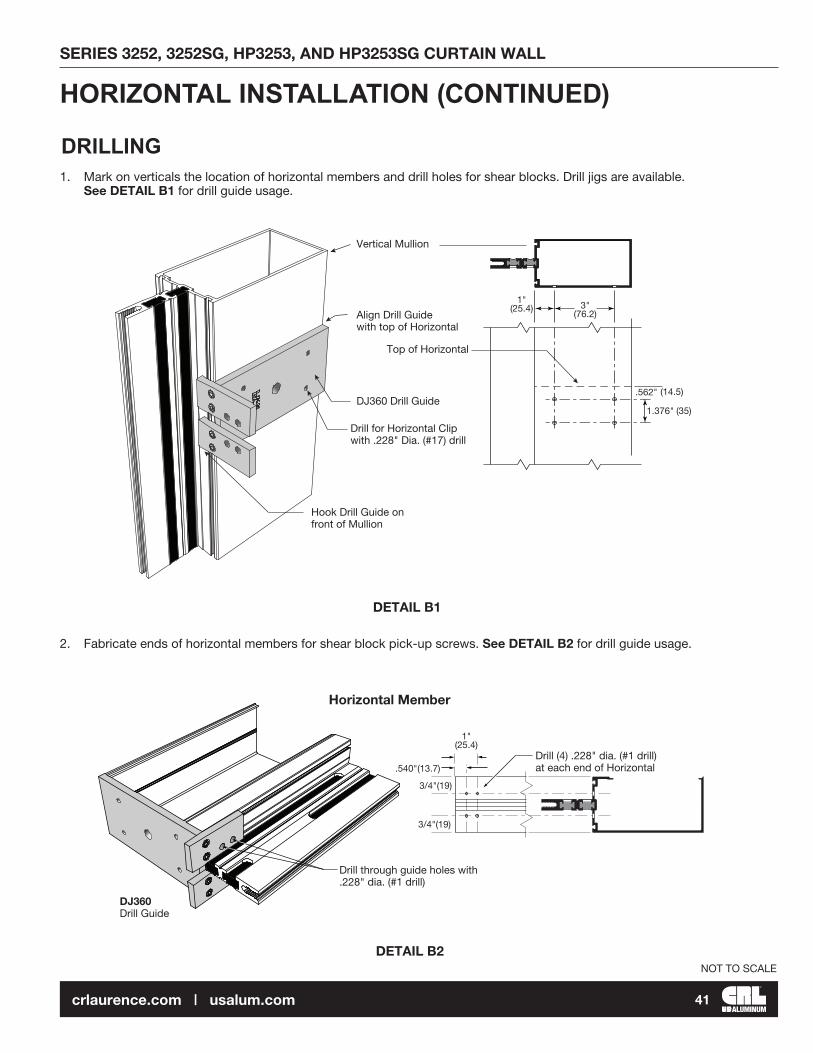
HORIZONTAL INSTALLATION (CONTINUED)
DRILLING1. Mark on verticals the location of horizontal members and drill holes for shear blocks. Drill jigs are available. See DETAIL B1 for drill guide usage.
2. Fabricate ends of horizontal members for shear block pick-up screws. See DETAIL B2 for drill guide usage.
DETAIL B1
DETAIL B2
Vertical Mullion
Top of Horizontal
Align Drill Guide with top of Horizontal
DJ360 Drill Guide
Drill for Horizontal Clip with .228" Dia. (#17) drill
Hook Drill Guide on front of Mullion
Horizontal Member
DJ360 Drill Guide
Drill (4) .228" dia. (#1 drill) at each end of Horizontal
1"(25.4)
3/4"(19)
3/4"(19)
.540"(13.7)
1"(25.4) 3"
(76.2)
.562"
1.376"
Drill through guide holes with .228" dia. (#1 drill)
(14.5)
(35)
NOT TO SCALE
SERIES 3252, 3252SG, HP3253, AND HP3253SG CURTAIN WALL
ALUMINUM41crlaurence.com | usalum.com

HORIZONTAL INSTALLATION (CONTINUED)ATTACHING AND SEALING THE HORIZONTAL MEMBERS
DETAIL B3
DETAIL B4
1. Roll horizontal members over shear blocks and secure them with screws provided. See DETAIL B4.2. Seal joint between horizontal and vertical. Also seal over head of screws in the glazing pockets.3. Apply sealant at the three contact areas of end dams. Also fill the vertical gasket reglet with sealant at the end dam location. See DETAIL B5. Slide end dams into place. NOTE: End dams occur at head and sill also.4. Using the Drill Jig DJ360, drill holes as illustrated below. See DETAIL B3
Top and Field Shear Blocks with relief facing down.
Top and Field Shear Blocks with relief facing down.
Bottom Sill Shear Blocks with relief facing up.
Top and Field Horizontal Members with openings facing upwards.
Bottom Sill Horizontal Members with openings facing down.
Ribs
RibsUp
RibsDown
RibsDown
7.00”(177.8)
2.25”(57.2)
2.25”(57.2)
Secure Horizontal Members with (4) #12 X 3/4" Pan HeadFasteners on top and bottom.
Drill for Horizontal Load Brackets with .147" (#26) drill. (6) total through holes top and bottom.
Drill for Horizontal Load Bracket with 5/16" Dia. drill.(3) through holes.
DJ 360 Drill Guide
Drill Guide must be held tight against the Vertical Member Glazing Fin while drilling holes.
NOT TO SCALE
SERIES 3252, 3252SG, HP3253, AND HP3253SG CURTAIN WALL
ALUMINUM42crlaurence.com | usalum.com

DETAIL B5
Please return to the Standard 3250 Installation Manual for the completion of the installation procedure.
The NP430 Gaskets must be notched on all vertical pressure bars in order to provide clearance for the HD885 End Dams.
Notch 5/8" X 3/8" Deep
HORIZONTAL INSTALLATION (CONTINUED)
CRITICAL SEAL Apply RTV408 Silicone Sealant to three contact areas.
CRITICAL SEAL Fill the Vertical Gasket Reglet with RTV408 Silicone Sealant behind the End Dam.
CRITICAL SEAL Seal Horizontal/Vertical Joint Intersection with RTV408 Silicone Sealant
CRITICAL SEAL Seal over heads of screws with Cat. No. 33S Silicone
NOTE: Consult sealant manufacturer for proper cleaning and priming recommendations
End Dam HD885 for 3253 2" glazing system
NOT TO SCALE
SERIES 3252, 3252SG, HP3253, AND HP3253SG CURTAIN WALL
ALUMINUM43crlaurence.com | usalum.com

GUIDE TO SEALANTSALUMINUM
NOTE: I�G� butyl contact OK�
NOTE: Not for use near insulated glass units with butyl sealant�
PERIMETER• 95C NEUTRAL CURE SILICONE
(Preferred)• M64 (SMOOTH) MODIFIED
POLYURETHANE • M66 (TEXTURED) MODIFIED
POLYURETHANE Perimeter Seals, Expansion Joints, Sill and Threshold Beds, Concrete, Wood and Steel Openings�
WATERPROOFING• 33S ACETIC CURE SILICONE
Sill to Subsill, End Dams, Screw Heads and Threshold to Door Frame Sealing�
JOINT ADHESIVE• RTV408 NEUTRAL CURE SILICONE
Small Joints, End Joints and Buttered Surfaces, Water Diverters, End Dams and Reglet Fills�
EXPANSION• 95C NEUTRAL CURE SILICONE
Expansion Joints�
STRUCTURAL • ALL STRUCTURAL SEALANTS
REQUIRE TESTING AND APPROVAL.Glass to Glass or Glass to Metal
NOTE: All sealants must be tooled to ensure proper adhesion.
1/2” (12.7mm)GAP BELOW
Bond Breaker TapeCAT.NO. 827T
Expansion Direction
Seal Tape Edges CAT. NO. 95C
Seal GapCAT.NO. 95C
Seal Screw Heads in Slotted (Expansion) Holes.CAT.NO. 95C
Fill with Sealant to Create a Water Shed.CAT.NO. 33S
Seal Over Screw HeadsCAT.NO. 33S
Exterior Perimeter CaulkingCAT. NO. 95C/M64/M66
Waterproofing Silicone SealantCAT. NO. 33S/RTV408 Do Not Block Weep holes
Exterior Perimeter CaulkingCAT. NO. 95C/M64/M66
Seal Screw HeadsCAT. NO. RTV408
Seal Vertical Gasket RegletCAT. NO. RTV408
Seal Water DiverterCAT. NO. RTV408
Butter Ends Before AssemblyCAT. NO. RTV408
Fill screw riglet ends with CAT.NO. RTV408
SERIES 3252, 3252SG, HP3253, AND HP3253SG CURTAIN WALL
ALUMINUM44crlaurence.com | usalum.com

CRL12:1 Ratio Strap Frame Caulking Gun
CAT. NO. GA1203
CRL Complete Set of Seven All Stainless Steel Spatulas
CAT. NO. AB958G
CRL Backer Rod Roller Tool
CAT. NO. SBRR
CRL PBS Series Plastic Bearing Shimstrips
JOB SITE ESSENTIALSHelpful Tools and Supplies for Installing CRL U.S. Aluminum Entrances, Storefronts, Windows, and Curtain Wall SystemsALUMINUM
CRL Spring ClampCAT. NO. JC3202HT
CRL GlovesCAT. NO. KF1TL
CRL Utility KnifeCAT. NO. K82
CRL Utility Knife BladesCAT. NO. 1992C
CRL Soft-Face Power HitterCAT. NO. ST57532
CRL 95C Silicone Building Sealant
CRL RTV408 Neutral Cure Silicone
CRL33S Silicone Sealant
CRL M64 Modified Smooth Polyurethane Construction Sealant
CRL M66 Modified Grainy Polyurethane Construction Sealant
CRL Plastic Horseshoe Shims
CRL Saint-Gobain/Norton V2100 Thermalbond® Structural
Glazing Spacer Tape
SERIES 3252, 3252SG, HP3253, AND HP3253SG CURTAIN WALL
ALUMINUM45crlaurence.com | usalum.com

CRL Gasket RollerCAT. NO. VR10
CRL Gasket CutterCAT. NO. MC80N
CRL Glass CleanerCAT. NO. 1973
CRL Glass WipesCAT. NO. 1550
CRL Tape MeasureCAT. NO. 54125
CRL Glazier’s Rule HolderCAT. NO. RH670
CRL Phenolic L SquareCAT. NO. L48
CRL Glass Marking PencilCAT. NO. GM44
CRL Belt SanderCAT. NO. LD321
CRL Glass Grinding Belts CRL All Terrain DollyCAT. NO. ATD1
CRL Cordless Driver/DrillCAT. NO. LD147
CRL Bond Breaker Tape
CRL Glass Cutter CAT. NO. TC17B
CRL Running Pliers CAT. NO. PPG1
CRL Vacuum Cups CAT. NO. S7950
CRL Cordless ScrewdriverCAT. NO. LD823
CRL Digital Laser Level ToolCAT. NO. 406065
CRL Hard Hat CAT. NO. ES3452
CRL Portable LadderCAT. NO. 6206
SERIES 3252, 3252SG, HP3253, AND HP3253SG CURTAIN WALL
ALUMINUM46crlaurence.com | usalum.com