installation instructions - startseite
TRANSCRIPT

ContentsPage
IMPORTANT!Please Read Before Starting .................................. 2
1. GENERAL .......................................................... 31-1. Tools Required for Installation (not supplied)1-2. Accessories Supplied with Unit1-3. Optional Copper Tubing Kit1-4. Type of Copper Tube and Insulation Material1-5. Additional Materials Required for Installation
2. INSTALLATION SITE SELECTION ................... 42-1. Indoor Unit2-2. Connecting Indoor Units2-3. Outdoor Unit2-4. Outer Dimensions of Outdoor Unit2-5. Diagram of Outdoor Unit Installation
3. INSTALLATION PROCESS .............................. 133-1. Embedding the Tubing and Wiring3-2. Drain Cap and Drain Elbow3-3. Use of the Flaring Method3-4. Flaring Procedure with a Flare Tool3-5. Caution Before Connecting Tubes Tightly3-6. Tubing Connections3-7. Insulation of Refrigerant Tubing3-8. Taping the Tubes3-9. Finishing the Installation
4. AIR PURGING................................................... 16� Air Purging with a Vacuum Pump (for Test Run)� Pump Down
5. WIRING INSTRUCTIONS ................................ 195-1. General Precautions on Wiring5-2. Recommended Wire Length and Diameter5-3. Wiring System Diagram5-4. How to Connect Wiring to the Terminal5-5. Wiring Instructions for the Outdoor Unit
6. TEST RUN ......................................................... 23
7. CONNECTING A HOME AUTOMATIONDEVICE ............................................................. 24
8. INSTALLATION CHECK SHEET ...................... 24
9. ELECTRIC WIRING DIAGRAM ........................ 25
Model Combinations
Combine indoor and outdoor units only as listedbelow.
Indoor Unit Outdoor Unit
AWMI22AHL AE2MI40AH
AWMI27AHL AE2MI56AHB
AWMI35AHL AE3MI68AH
AWI52AHL AE4MI80AH
AWI68AHL
Combine indoor and outdoor units only as listed inthe combination tables for 2-room, 3-room or 4-room outdoor unit as shown in its respective manual.
Power Source:50 Hz, single-phase, 220 – 240 VAC
This air conditioner uses the new refrigerant R410A.
Be sure to read the yellow instruction sheetattached to the outdoor unit for models using thenew refrigerant R410A.
The illustrations are based on the typical appearance ofa standard model. Consequently, the shape may differfrom that of the air conditioner that you are installing.
NOTE
Indoor unit A
Indoor unit B
Indoor unit C
Indoor unit D
Outdoor unit
Combination example
For Outdoor Unit
85264190444000 12/2007
Italiano
En
glish
INSTALLATION INSTRUCTIONS– Multi Split system air conditioner –
COOL/DRY/HEAT Model
07-336 AE4MI80AH_OU ENG 11/7/07 4:29 PM Page a

2
En
glis
h
IMPORTANT! Please Read Before Starting
This air conditioning system meets strict safety and oper-ating standards. As the installer or service person, it is animportant part of your job to install or service the systemso it operates safely and efficiently.
For safe installation and trouble-free operation, youmust:� Carefully read this instruction booklet before beginning.� Follow each installation or repair step exactly as
shown.� Observe all local, state, and national electrical codes.� Pay close attention to all warning and caution notices
given in this manual.This symbol refers to a hazardor unsafe practice which canresult in severe personal injuryor death.
This symbol refers to a hazardor unsafe practice which canresult in personal injury orproduct or property damage.
If Necessary, Get HelpThese instructions are all you need for most installationsites and maintenance conditions. If you require help for aspecial problem, contact our sales/service outlet or yourcertified dealer for additional instructions.
In Case of Improper InstallationThe manufacturer shall in no way be responsible forimproper installation or maintenance service, includingfailure to follow the instructions in this document.
SPECIAL PRECAUTIONS
When Wiring
ELECTRICAL SHOCK CAN CAUSESEVERE PERSONAL INJURY OR DEATH.ONLY A QUALIFIED, EXPERIENCED ELEC-TRICIAN SHOULD ATTEMPT TO WIRETHIS SYSTEM.
• Do not supply power to the unit until all wiring and tub-ing are completed or reconnected and checked.
• Highly dangerous electrical voltages are used in thissystem. Carefully refer to the wiring diagram and theseinstructions when wiring. Improper connections andinadequate grounding can cause accidental injury ordeath.
• Ground the unit following local electrical codes.• Connect all wiring tightly. Loose wiring may cause over-
heating at connection points and a possible fire hazard.• Install a protective leakage breaker depending on the
installation location (especially a damp or humid loca-tion). If a leakage breaker is not installed, electricshock can occur.
When Transporting
Be careful when picking up and moving the indoor andoutdoor units. Get a partner to help, and bend your kneeswhen lifting to reduce strain on your back. Sharp edges orthin aluminum fins on the air conditioner can cut your fin-gers.
When Installing…
…In a Ceiling or WallMake sure the ceiling/wall is strong enough to hold theunit’s weight. It may be necessary to construct a strongwood or metal frame to provide added support.
…In a RoomProperly insulate any tubing run inside a room to prevent“sweating” that can cause dripping and water damage towalls and floors.
…In Moist or Uneven LocationsUse a raised concrete pad or concrete blocks to provide asolid, level foundation for the outdoor unit. This preventswater damage and abnormal vibration.
…In an Area with High WindsSecurely anchor the outdoor unit down with bolts and ametal frame. Provide a suitable air baffle.
…In a Snowy Area (for Heat Pump-type Systems)• Position the outdoor unit in a protected location
where snow will not blow into it.• Install the outdoor unit on a raised platform that is
higher than drifting snow. Provide snow vents.
When Connecting Refrigerant Tubing
• Use the flare method for connecting tubing.
• Apply refrigerant lubricant to the matching surfaces ofthe flare and union tubes before connecting them, thentighten the nut with a torque wrench for a leak-free con-nection.
• Check carefully for leaks before starting the test run.
When Servicing
• Turn the power OFF at the main power box (mains)before opening the unit to check or repair electricalparts and wiring.
• Keep your fingers and clothing away from any movingparts.
• Clean up the site after you finish, remembering to checkthat no metal scraps or bits of wiring have been leftinside the unit being serviced.
Others
• Ventilate any enclosed areas when installing or testingthe refrigeration system. Escaped refrigerant gas, oncontact with fire or heat, can produce dangerously toxicgas.
• Confirm upon completing installation that no refrigerantgas is leaking. If escaped gas comes in contact with astove, gas water heater, electric room heater or otherheat source, it can produce dangerously toxic gas.
• Do not install only a single indoor unit.
WARNING
WARNING
CAUTION
CAUTION
07-336 AE4MI80AH_OU ENG 11/7/07 4:29 PM Page 2

3
En
glish
1. General
This booklet briefly outlines where and how to installthe air conditioning system. Please read over theentire set of instructions for the indoor and outdoorunits and make sure all accessory parts listed are withthe system before beginning. If the electric wiring dia-gram does not appear in this manual, please check forthe diagram on the indoor unit.
1-1. Tools Required for Installation (not supplied)1. Standard screwdriver2. Phillips head screwdriver3. Knife or wire stripper4. Tape measure
5. Carpenter’s level6. Sabre saw or key hole saw7. Hacksaw8. Core bits9. Hammer
10. Drill11. Tube cutter12. Tube flaring tool13. Torque wrench14. Adjustable wrench15. Reamer (for deburring)16. Vacuum pump (For R410A)17. Manifold valve
1-2. Accessories Supplied with Unit
Table 1
1-3. Optional Copper Tubing Kit
Copper tubing for connecting the outdoor unit to theindoor unit is available in kits which contain the narrowand wide tubing, fittings and insulation. Consult yournearest sales outlet or Air Conditioner workshop.
1-4. Type of Copper Tube and Insulation Material
If you wish to purchase these materials separatelyfrom a local source, you will need:
1. Deoxidized annealed copper tube for refrigeranttubing as detailed in Table 2.
Cut each tube to the appropriate lengths +30 cmto 40 cm to dampen vibration between units.
ModelNarrow Tube Wide Tube
Outer Dia. Thickness Outer Dia. Thickness
AWMI22 6.35 mm 0.8 mm 9.52 mm 0.8 mm
AWMI27 6.35 mm 0.8 mm 9.52 mm 0.8 mm
AWMI35 6.35 mm 0.8 mm 9.52 mm 0.8 mm
AWI52 6.35 mm 0.8 mm 12.70 mm 0.8 mm
AWI68 6.35 mm 0.8 mm 15.88 mm 1.0 mm
Labels for inter-unitcable and tube
Cushion rubber 4 Drain cap
Packed in the outdoor unit.
1AE2MI561AE3MI68
2
4each
5
4
AE4MI80
AE2MI56/AE3MI68/AE4MI80
AE2MI40
1Drain elbow
Parts Figure Q’ty Parts Figure Q’ty
Reducer(ø9.52 ø12.70)
Reducer(ø12.70 ø9.52)
A B C D
Table 2
2. Foamed polyethylene insulation for the specifiedcopper tubes as required to precise length of tub-ing. Wall thickness of the insulation should be notless than 8 mm.
3. Use insulated copper wire for field wiring. Wire size varies with the total length of wiring.Refer to 5. Wiring Instructions for details.
CAUTIONCheck local electrical codesand regulations beforeobtaining wire. Also, checkany specified instructions orlimitations.
07-336 AE4MI80AH_OU ENG 11/7/07 4:29 PM Page 3

4
En
glis
h
1-5. Additional Materials Required for Installation
1. Refrigeration (armored) tape2. Insulated staples or clamps for connecting wire
(See local codes)3. Putty4. Refrigeration lubricant5. Clamps or saddles to secure refrigerant tubing
2. Installation Site Selection
2-1. Indoor Unit
AVOID:
� direct sunlight.
� nearby heat sources that may affect performance of theunit.
� areas where leakage of flammable gas may be expected.
� placing or allowing any obstructions near the Air Condi-tioner inlet or outlet.
� installing in rooms that contain instant-on (rapid-start) fluorescent lamps. (These may prevent the Air Conditionerfrom receiving signals.)
� places where large amounts of oil mist exist.
� installing in locations where there are devices that generate high-frequency emissions.
DO:
� select an appropriate position from which every corner ofthe room can be uniformly cooled. (High on a wall is best.)
� select a location that will hold the weight of the unit.
� select a location where tubing and drain hose have theshortest run to the outside. (Fig. 1)
� allow room for operation and maintenance as well as unrestricted air flow around the unit. (Fig. 2)
� install the unit within the maximum elevation difference (H1, H2, H3, H4) above or below the outdoor unit and within a total tubing length (L1+L2, L1+L2+L3,L1+L2+L3+L4) from the outdoor unit as detailed in Table 3 and Fig. 3a.
Drain hose
Indoor unit
Outside drainage
Fig. 1
5 cmmin.
5 cmmin.
15 cm min.
Front View
Fig. 2
INDOORUNIT (1)
INDOORUNIT (4)
INDOORUNIT (3)
INDOORUNIT (2)
Tubing length (L1)
L2
L3
L4
H2
H3H4
OUTDOORUNIT
Elevationdifference (H1)
Fig. 3a
WARNINGTo prevent abnormal heat generationand the possibility of fire, do notplace obstacles, enclosures andgrilles in front of or surrounding theair conditioner in a way that mayblock air flow.
Indoor unit
Floor level
Wall
Minimum height from floor level
1.5 m
Fig. 3b
For stable operation of the airconditioner, do not installwall-mounted type indoorunits less than 1.5 m fromfloor level.
CAUTION
07-336 AE4MI80AH_OU ENG 11/7/07 4:29 PM Page 4

5
En
glish
� Install the indoor unit more than 1 meter away from anyantenna or power lines or connecting wires used for tele-vision, radio, telephone, security system, or intercom.Electrical noise from any of these sources may affectoperation.
� install in a sturdy manner to avoid increased operatingnoise.
Table 3
* If total tubing length becomes 45 to 60 m (max.) or 45 to 70 m (max.), charge additional refrigerant (R410A) by 20 g/m.No additional charge of compressor oil is necessary.
2-2. Connecting Indoor Units
(1) Connecting indoor unit for AE2MI40AH
ø12.70Unionø9.52Flare
A joint for connecting tubes ofdifferent sizes(ø9.52 ø12.70) Supplied Reducer
ø9.52
ø6.35ø12.70
ø6.35
ø9.52
B
ø9.52
A
Outdoor unit Indoor unit
(AWMI22/27/35AHL)
(AWI52AHL)
ø9.52
ø6.35ø9.52
ø6.35
ø9.52
B
ø9.52
A
Outdoor unit Indoor unit
(AWMI22/27/35AHL)
(AWMI22/27/35AHL)
(A)
(B)
Max. Allowable Max. Allowable Total Limit of Limit of Elevation Required AmountTubing Length Tubing Length Total Tubing Length Difference of Additional
Model per unit at shipment (L1+L2) or (L1+L2+L3) (H1, H2, H3, H4) Refrigerant(m) (L1+L2) or (L1+L2+L3) or (L1+L2+L3+L4) (m) (g/m)*
or (L1+L2+L3+L4) (m)(m)
AE2MI40 20 30 (L1+L2) 30 (L1+L2) 15 –
AE2MI56 25 45 (L1+L2) 45 (L1+L2) 15 –
AE3MI68 25 45 (L1+L2+L3+L4) 60 (L1+L2+L3+L4) 15 20
AE4MI80 30 45 (L1+L2+L3+L4) 70 (L1+L2+L3+L4) 15 20
(2) Connecting indoor unit for AE2MI56AHB
unit: mm
Fig. 4b
Fig. 4c
ø9.52
ø6.35ø9.52
ø6.35
ø9.52
B
ø9.52
A
Outdoor unit Indoor unit
(AWMI22/27/35AHL)
(AWMI22/27/35AHL)
Fig. 4a
07-336 AE4MI80AH_OU ENG 11/7/07 4:29 PM Page 5

6
En
glis
h
(A)
Fig. 4d
ø9.52Unionø12.70Flare
(ø12.70 ø9.52) Supplied Reducer
ø9.52
ø9.52
ø6.35ø9.52
ø6.35ø9.52
ø6.35
C
ø9.52
B
ø12.70
A
(AWMI22/27/35AHL)
(AWMI22/27/35AHL)
ø9.52
ø9.52
ø6.35
D
Outdoor unit Indoor unit
(AWMI22/27/35AHL)
(AWMI22/27/35AHL)
(3) Connecting indoor unit for AE3MI68AH
(B)
Fig. 4e
ø9.52
ø9.52
ø6.35ø9.52
ø6.35ø12.70
ø6.35
C
ø9.52
B
ø12.70
A
(AWMI22/27/35AHL)
(AWMI22/27/35AHL)
ø9.52
ø9.52
ø6.35
D
Outdoor unit Indoor unit
(AWMI22/27/35AHL)
(AWI52AHL)
(C)
Fig. 4f
ø15.88Unionø12.70Flare
(ø12.70 ø15.88) Locally purchased
ø9.52
ø9.52
ø6.35ø9.52
ø6.35ø15.88
ø6.35
C
ø9.52
B
ø12.70
A
(AWMI22/27/35AHL)
(AWMI22/27/35AHL)
ø9.52
ø9.52
ø6.35
D
Outdoor unit Indoor unit
(AWMI22/27/35AHL)
(AWI68AHL)
unit: mm
07-336 AE4MI80AH_OU ENG 11/7/07 4:29 PM Page 6

(A)
Fig. 4h
ø9.52Unionø12.70Flare
(ø12.70 ø9.52) Supplied Reducer
ø9.52
ø9.52
ø6.35ø9.52
ø6.35ø9.52
ø6.35
C
ø12.70
B
ø12.70
A
(AWMI22/27/35AHL)
(AWMI22/27/35AHL)
ø9.52
ø9.52
ø6.35
D
Outdoor unit Indoor unit
(AWMI22/27/35AHL)
(AWMI22/27/35AHL)
(4) Connecting indoor unit for AE4MI80AH
(B)
Fig. 4i
ø9.52Unionø12.70Flare
(ø12.70 ø9.52) Supplied Reducer
ø9.52
ø9.52
ø6.35ø9.52
ø6.35ø12.70
ø6.35
C
ø12.70
B
ø12.70
A
(AWMI22/27/35AHL)
(AWMI22/27/35AHL)
ø9.52
ø9.52
ø6.35
D
Outdoor unit Indoor unit
(AWMI22/27/35AHL)
(AWI52AHL)
7
En
glish
(D)
Fig. 4g
ø15.88Unionø12.70Flare
(ø12.70 ø15.88)Locally purchased
ø9.52
ø9.52
ø6.35ø12.70
ø6.35ø15.88
ø6.35
C
ø9.52
B
ø12.70
A
(AWI52AHL)
(AWMI22/27/35AHL)
ø9.52
ø9.52
ø6.35
D
Outdoor unit Indoor unit
(AWMI22/27/35AHL)
(AWI68AHL)
ø12.70Unionø9.52Flare
(ø9.52 ø12.70) Locally purchased
unit: mm
07-336 AE4MI80AH_OU ENG 11/7/07 4:29 PM Page 7

8
En
glis
h
(C)
Fig. 4j
ø9.52
ø9.52
ø6.35ø12.70
ø6.35ø12.70
ø6.35
C
ø12.70
B
ø12.70
A
(AWI52AHL)
(AWMI22/27/35AHL)
ø9.52
ø9.52
ø6.35
D
Outdoor unit Indoor unit
(AWMI22/27/35AHL)
(AWI52AHL)
(D)
Fig. 4k
ø15.88Unionø12.70Flare
(ø12.70 ø15.88) Locally purchased
ø9.52
ø9.52
ø6.35ø9.52
ø6.35ø15.88
ø6.35
C
ø12.70
B
ø12.70
A
(AWMI22/27/35AHL)
(AWMI22/27/35AHL)
ø9.52
ø9.52
ø6.35
D
Outdoor unit Indoor unit
(AWMI22/27/35AHL)
(AWI68AHL)
ø9.52Unionø12.70Flare
(ø12.70 ø9.52) Supplied Reducer
(E)
Fig. 4l
ø15.88Unionø12.70Flare
(ø12.70 ø15.88) Locally purchased
ø9.52
ø9.52
ø6.35ø12.70
ø6.35ø15.88
ø6.35
C
ø12.70
B
ø12.70
A
(AWI52AHL)
(AWMI22/27/35AHL)
ø9.52
ø9.52
ø6.35
D
Outdoor unit Indoor unit
(AWMI22/27/35AHL)
(AWI68AHL)
unit: mm
07-336 AE4MI80AH_OU ENG 11/7/07 4:29 PM Page 8

Air intake Min. 10 cm
Air dischargeMin.5 cm
Min.40 cm
ValvesideMin. 25 cm
Min.2 m
Min.2 m
Ground
Obs
tacl
e
Obstacle above
Air
disc
harg
e
Min. 10 cmAir intake
9
En
glish
2-3. Outdoor Unit
AVOID:
� heat sources, exhaust fans, etc. (Fig. 5a)
� damp, humid or uneven locations.
DO:
� position the outdoor unit in a protected location where snow will not blow into it.
� choose a place as cool as possible.
� choose a place that is well ventilated.
� allow enough room around the unit for air intake/exhaust and possible maintenance. (Fig. 5b-1 or 5b-2)
� provide a solid base (level concrete pad, concreteblock, 10 × 40 cm or 15 × 40 cm beams or equal), aminimum of 10 cm or 15 cm above ground level toreduce humidity and protect the unit against possiblewater damage and decreased service life. (Fig. 5c-1 or 5c-2)
� Install cushion rubber under unit’s feet to reducevibration and noise. (Fig. 5d)
� use lug bolts or equal to bolt down unit, reducingvibration and noise.
� Install in a location where no antenna of a televisionor radio exists within 3 meters.
Outdoor unit
Hot airHeat source
Exhaust fanNO
Fig. 5a
Fig. 5c-2
Air intake Min. 20 cm
Air dischargeMin.10 cm
Min.50 cm
ValvesideMin. 25 cm
Min.2 m
Min.2 m
GroundO
bsta
cle
Obstacle above
Air
disc
harg
e
Min. 20 cmAir intake
Air intake
Concreteor equal
About 15 cm
Min. 15 cm
Anchor bolts(4 pcs.)
About 40 cm
Fig. 5d
Cushion rubber
Fig. 5b-1
Fig. 5b-2
Fig. 5c-1
Air intake
Concreteor equal
About 10 cm
Min. 10 cm
Anchor bolts(4 pcs.)
About 40 cm
(AE2MI40)
(AE2MI56, AE3MI68, AE4MI80)
(AE2MI40)
(AE2MI56, AE3MI68, AE4MI80)
07-336 AE4MI80AH_OU ENG 11/7/07 4:29 PM Page 9

10
En
glis
h
(2) AE2MI56AHB
(3) AE3MI68AH
(4) AE4MI80AH
2-4. Outer Dimensions of Outdoor Unit
608 13612
320
345
369
900
740
85
A
11451
150
7270
70
113
7570
70
Service valve on narrow tube side(Outer diameter ø6.35)
Service valve on wide tube side(Outer diameter ø9.52)
Service valve on wide tube side(Outer diameter ø12.70)
A
18
60812
320
345
369
136
900
1889
0
85
11451
113
150 75
73
70
70
70
70
A
Service valve on narrow tube side(Outer diameter ø6.35)
Service valve on wide tube side(Outer diameter ø12.70)
Service valve on wide tube side(Outer diameter ø9.52)
A
608 13612
900
345
320
369
85
740
18 150
72
51
113
75
114
A
(Outer diameter ø6.35)
(Outer diameter ø9.52)
A
Service valve on wide tube side
Service valve on narrow tube side
Fig. 6d
unit: mm
Fig. 6c
Fig. 6b
(1) AE2MI40AH
608 85 790
310
285
336
70
569
15 158
70
46
122
70
142
A
A(Outer diameter ø6.35)
(Outer diameter ø9.52)
Service valve on wide tube side
Service valve on narrow tube side
Fig. 6a
07-336 AE4MI80AH_OU ENG 11/7/07 4:29 PM Page 10

11
En
glish
2-5. Diagram of Outdoor Unit Installation
Never install only a single indoor unit.
Be sure to connect indoor and outdoor units only in combinations that are listed in the catalog or in the combination table that was provided with the outdoor unit.(Use caution. Connecting any other model may result in operation failure and malfunction.)
The dimensions indicated by in the figure below are spaces that are required in order to maintain performance. Install in a location where the dimensions indicated by are ensured, and where 2 or more faces of the unit are unobstructed. In principle, the top direction should be unobstructed.
Indoor unit B
Indoor unit A
Service space
Power breaker
Groundwire(not provided)
Ensure 15cmof space if adrain hose is tobe used.
Base (not provided)(concrete or similar material)
Fasten with anchor bolts (not provided) (3/8" or M10, 4 locations)
AB Access panel C
Over 25cm
Over 10cmOver 5cm
Over 40cm
(1) AE2MI40AH
Fig. 6e
07-336 AE4MI80AH_OU ENG 11/7/07 4:29 PM Page 11

12
En
glis
h
Be sure to connect indoor and outdoor units only in combinations that are listed in the catalog or in the combination table that was provided with the outdoor unit.(Use caution. Connecting any other model may result in operation failure and malfunction.)
The dimensions indicated by in the figure below are spaces that are required in order to maintain performance. Install in a location where the dimensions indicated by are ensured, and where 2 or more faces of the unit are unobstructed. In principle, the top direction should be unobstructed.
Indoor unit C
Indoor unit B
Indoor unit A
Indoor unit D
Service space
Power breaker
Groundwire(not provided)
Ensure 15cmof space if adrain hose is tobe used.
Base (not provided)(concrete or similar material)
Fasten with anchor bolts (not provided) (3/8" or M10, 4 locations)
ABCD
Access panel C
Over 25cm
Over 20cm
Over 10cm
Over 50cm
Fig. 6f
(2) AE2MI56AHB, AE3MI68AH, AE4MI80AH
07-336 AE4MI80AH_OU ENG 11/7/07 4:29 PM Page 12

13
En
glish
3. Installation Process
3-1. Embedding the Tubing and Wiring
� Do not connect tubes to locations that are embedded.
� Be sure to bind refrigerant tubing and inter-unit cablestogether with vinyl tape.
� The power cable must be obtained on-site. (ø3.5: Less than 26 m)
� Be sure to apply the provided labels to both ends ofthe inter-unit cables to prevent miswiring.
� Securely seal the end of embedded tubing with vinyltape in order to prevent dirt or moisture entry.
� In order to prevent insulation breakdown and groundfaults, do not allow the wire ends to contact rainwater,or be subject to dew condensation.
Deburring
Before After
Fig. 8
3-3. Use of the Flaring Method
Many of the conventional split system air conditionersemploy the flaring method to connect refrigerant tubeswhich run between indoor and outdoor units. In thismethod, the copper tubes are flared at each end andconnected with flare nuts.
3-4. Flaring Procedure with a Flare Tool
(1) Cut the copper tube to the required length with atube cutter. It is recommended to cut approx. 30 –50 cm longer than the tubing length you estimate.
(2) Remove burrs at the end of the copper tube with atube reamer or file. This process is important andshould be done carefully to make a good flare. (Fig. 8)
3-2. Drain Cap and Drain Elbow
First refer to Section 2. Installation Site Selection.
The drain hole at the bottom of the outdoor unit was notplugged at the time of factory shipment. If necessary,plug the drain hole with the accessory drain cap ormount the accessory drain elbow before installing theoutdoor unit. (Fig. 7a or 7b)
NOTE
Accessorydrain cap
Accessorydrain capAccessory
drain elbow
Outdoor unit
Fig. 7bCAUTIONWhen installing in a coldarea where drainage watermay freeze, do not attach theprovided drain cap or drainelbow to the bottom plate ofthe unit.
Accessorydrain cap
Accessorydrain capAccessory
drain elbow
Outdoor unit
Fig. 7a
(AE2MI40)
(AE2MI56, AE3MI68, AE4MI80)
07-336 AE4MI80AH_OU ENG 11/7/07 4:29 PM Page 13

14
En
glis
h
When reaming, hold the tube end downward and be surethat no copper scraps fall into the tube. (Fig. 9)
(3) Remove the flare nut from the unit and be sure to mountit on the copper tube.
(4) Make a flare at the end of copper tube with a flare tool.*(Figs. 10 and 11)
(*Use “RIDGID” or equivalent.)
A good flare should have the following characteristics:
� inside surface is glossy and smooth.
� edge is smooth.
� tapered sides are of uniform length.
3-5. Caution Before Connecting Tubes Tightly
a) Be sure to apply a sealing cap or water-proof tape toprevent dust or water from getting into the tubes beforethey are used.
b) Be sure to apply refrigerant lubricant to the matching surfaces of the flare and union before connecting themtogether. This is effective for reducing gas leaks. (Fig. 12)
c) For proper connection, align the union tube and flaretube straight with each other, then screw in the flare nutlightly at first to obtain a smooth match. (Fig. 13)
3-6. Tubing Connections
a) Temporary connection:Screw in 3 – 5 rotations by hand. (Fig.14)
b) To fasten the flare nuts, apply specified torque as:
Table 4
NOTE
NOTE
Reamer
Coppertubing
Fig. 9
Flare tool
Flare nut
Copper tubing
Fig. 11
Fig. 10
Apply refrigerant lubricant here and here
Fig. 12
Flare nutUnion
Fig. 13
0 – 0.5 mm
If the special R410A flare tool is used:
1.2 mm
If the previous flare tool (clutch-type) is used:
Adjust so that the amount of tube protrusion is as shown in the figure.
Apply the provided labels to the indoor and outdoor unit tubing connectors to prevent errors in connections.
Service valve on narrow tube side
Service valve on wide tube side
ABCD
Fig. 14
Tube Dia. Tightening Torque
6.35 mm 14 – 18 N·m (140 – 180 kgf · cm)
9.52 mm 34 – 42 N·m (340 – 420 kgf · cm)
12.70 mm 49 – 61 N·m (490 – 610 kgf · cm)
15.88 mm 68 – 82 N·m (680 – 820 kgf · cm)
07-336 AE4MI80AH_OU ENG 11/7/07 4:29 PM Page 14

15
En
glish3-7. Insulation of Refrigerant Tubing
To prevent heat loss and wet floors due to dripping of con-densation, both tubes must be well insulated with aproper insulation material.The thickness of the insulation should be a minimum 8 mm. (Fig. 17)
3-8. Taping the Tubes
(1) At this time, the 2 refrigerant tubes (and electrical wireif local codes permit) should be taped together witharmoring tape. The drain hose may also be includedand taped together as 1 bundle with the tubing.
(2) Wrap the armoring tape from the bottom of the outdoorunit to the top of the tubing where it enters the wall. Asyou wrap the tubing, overlap half of each previous tapeturn. (Fig. 18)
(3) Clamp the tubing bundle to wall, using 1 clamp approx.every 120 cm.
Do not wind the armoring tape too tightly, since this willdecrease the heat insulation effect. Also, be sure the con-densation drain hose splits away from the bundle and dripsclear of the unit and the tubing.
3-9. Finishing the Installation
After finishing insulating and taping over the tubing, usesealing putty to seal off the hole in the wall to prevent rainand draft from entering. (Fig. 19)
NOTE
IMPORTANT
Indoor unit
Outdoor unit
Spanner
Torque wrench
Fig. 15
Insulation
Min. 8 mm
Thickness:min. 8 mm
Fig. 17
Fig. 18
Clamp
Insulated tubes
Apply putty here
Tubing
Fig. 19
CAUTION After a tube has been insulated,never try to bend it into a narrow curve, as this maycause the tube to break orcrack.
Insulation
Fig. 16
CAUTION Be sure to match refrigeranttubing and electric wiringbetween indoor and outdoorunits. For more details, refer to“Tubing Check Control” in theTechnical & Service Manual.
07-336 AE4MI80AH_OU ENG 11/7/07 4:29 PM Page 15

16
En
glis
h
4. Air Purging
Air and moisture remaining in the refrigerant sys-tem have undesirable effects as indicated below. Therefore, they must be purged completely.
� pressure in the system rises
� operating current rises
� cooling efficiency drops
� moisture in the air may freeze and block capil-lary tubing
� water may lead to corrosion of parts in the refrigerant system
� Air Purging with a Vacuum Pump (for Test Run)
� In order to protect the earth’s environment, besure to use a vacuum pump to perform the airpurge.(Never perform an air purge by using the refrigerantgas cylinder or other external gas, or by using the gasinside the outdoor unit.)Perform the air purge for tubes A, B, C, and D. Use thesame procedures for all tubes.
(1) Check that each tube (both narrow and widetubes) between the indoor and outdoor units havebeen properly connected and all wiring for the testrun has been completed. Note that both narrowand wide tube service valves on the outdoor unitare kept closed at this stage.
(2) Using an adjustable wrench or box wrench,remove the valve caps from the service valve onboth narrow and wide tubes.
(3) Connect a vacuum pump and a manifold valve(with pressure gauges) to the service port on thewide tube service valve. (Fig. 20).
Fig. 20
Fig. 21
CAUTION Be sure to use a manifold valvefor air purging. If it is not available, use a stop valve forthis purpose. The “Hi” knob ofthe manifold valve must alwaysbe kept closed.
CAUTION
CAUTION Before using the vacuum pumpadapter, read the vacuum pumpadapter manual, and use theadapter correctly.
In order to prevent charging errors with AirConditioner that uses R410A, the screwdiameter at the service valve charging porthas been changed. When recharging orperforming other servicing, use the specialcharging hose and manifold gauge.
� When using a hex wrench to open the spindle, anextremely small amount of refrigerant may leak. This does not indicate a problem.
� Use a hex wrench of a type to which force can beeasily applied.
Service valve on wide tube side
Service valve on narrow
AB
CD
Vacuum pump
Vacuum pump adapter (for preventing reverse flow)(special for R410A)
High-pressure valve
Manifold gauge (special for R410A)
Low-pressure valve
Leave the valve open.
Open
Charging hose(special for R410A)
Hex wrench(nominal size 4mm, not provided)
With push-pin
HiLo
Cap tightening torque:20 – 25 N·m(200 – 250 kgf·cm)(Tighten by hand, then use a wrench to turn.)
Stopper
Spindle
Screw diameter: 1/2UNF 20 threads
Valve core
Cap nut tightening torque:7 – 11 N·m(70 – 110 kgf·cm)(Tighten by hand, then use a wrench to turn approximately 30 .)
<Structure of service valve on wide tube side>
07-336 AE4MI80AH_OU ENG 11/7/07 4:29 PM Page 16

17
En
glish
(4) With the “Lo” knob of the manifold valve open andhigh-pressure valve (“Hi”) closed completely, runthe vacuum pump. Run the pump until the pres-sure is –101 kPa (–76 cmHg). The operation timefor the vacuum pump varies with tubing length andthe capacity of the pump. The following tableshows the amount of time required for evacuation:
Table 5
The required time in the above table is calculatedbased on the assumption that the ideal (or target) vac-uum condition is around 10 mmHg abs.
(5) With the vacuum pump still running, close the “Lo”knob of the manifold valve. Then stop the vacuumpump. Fully close the low-pressure valve and stopthe vacuum pump. (Wait 1 – 2 minutes and checkthat the manifold gauge pointer does not return. Ifit does return, find and repair the leak, then applythe vacuum again.)
(6) With a hex wrench, turn the valve stem on the nar-row tube service valve counter-clockwise by 90degrees (1/4 turn) for 10 seconds, and then turnthe stem clockwise to close it again.
(7) With a standard screwdriver, turn the wide tubeservice valve stem counterclockwise to fully openthe valve.
(8) Turn the narrow tube service valve stem counter-clockwise to fully open the valve.
(9) Loosen the vacuum hose connected to the widetube service port slightly to release the pressure.Then, remove the hose.
(10) Leak test all joints at the tubing (both indoor andoutdoors) with liquid soap. Bubbles indicate a leak.Be sure to wipe off the soap with a clean cloth.
NOTE
CAUTION Be sure to completely insertthe hex wrench beforeattempting to turn the valve.
Required time for evacuation when capacityof 100 liter/h vacuum pump is used
20 min. or more
CAUTION If a CFC gas detector is used,use a special detector for HFCrefrigerant (such as R410A andR134a).
07-336 AE4MI80AH_OU ENG 11/7/07 4:29 PM Page 17
18
En
glis
h
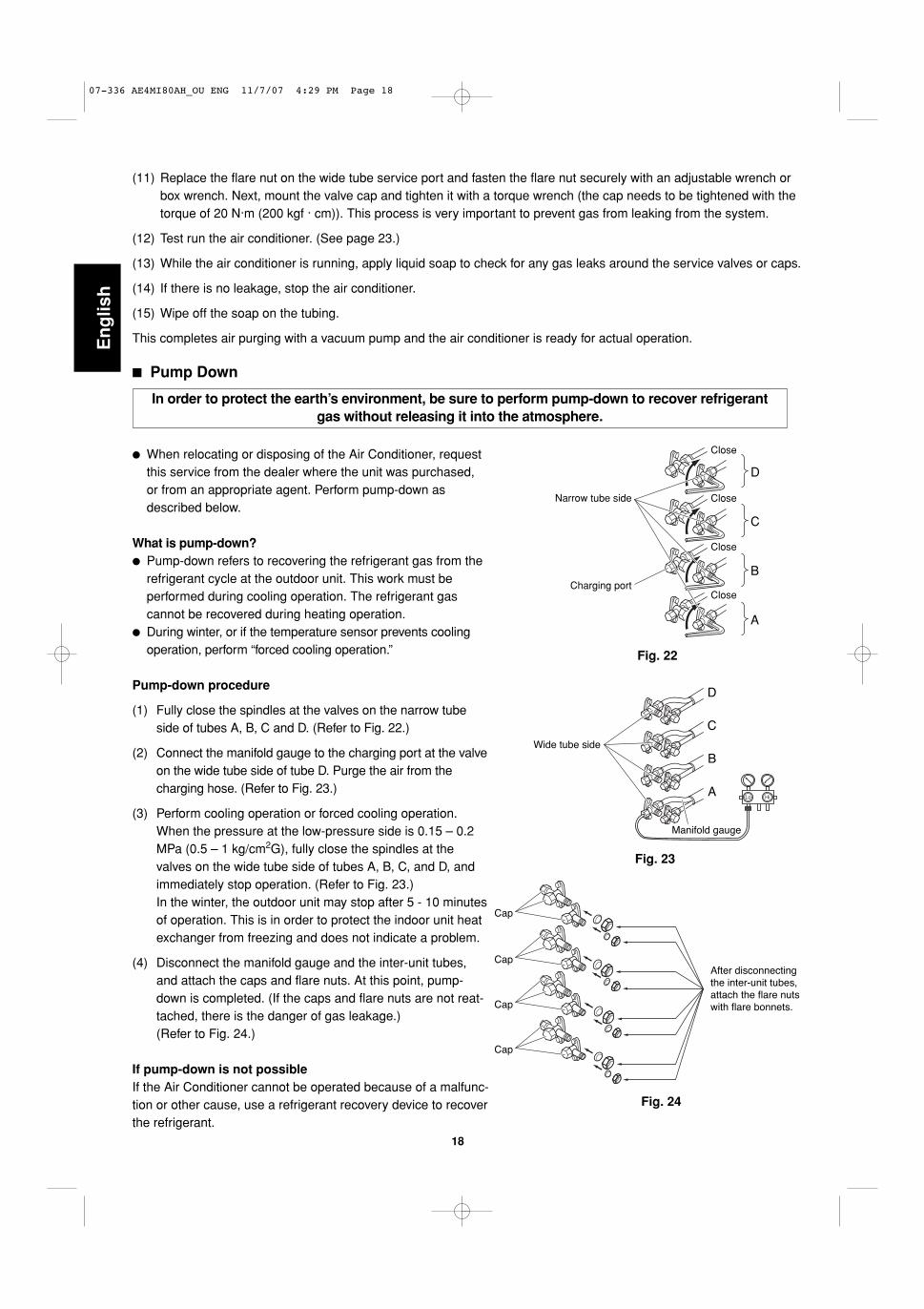
� Pump Down
� When relocating or disposing of the Air Conditioner, requestthis service from the dealer where the unit was purchased,or from an appropriate agent. Perform pump-down asdescribed below.
What is pump-down?� Pump-down refers to recovering the refrigerant gas from the
refrigerant cycle at the outdoor unit. This work must be performed during cooling operation. The refrigerant gas cannot be recovered during heating operation.
� During winter, or if the temperature sensor prevents coolingoperation, perform “forced cooling operation.”
Pump-down procedure
(1) Fully close the spindles at the valves on the narrow tubeside of tubes A, B, C and D. (Refer to Fig. 22.)
(2) Connect the manifold gauge to the charging port at the valveon the wide tube side of tube D. Purge the air from thecharging hose. (Refer to Fig. 23.)
(3) Perform cooling operation or forced cooling operation. When the pressure at the low-pressure side is 0.15 – 0.2MPa (0.5 – 1 kg/cm2G), fully close the spindles at thevalves on the wide tube side of tubes A, B, C, and D, andimmediately stop operation. (Refer to Fig. 23.)In the winter, the outdoor unit may stop after 5 - 10 minutesof operation. This is in order to protect the indoor unit heatexchanger from freezing and does not indicate a problem.
(4) Disconnect the manifold gauge and the inter-unit tubes,and attach the caps and flare nuts. At this point, pump-down is completed. (If the caps and flare nuts are not reat-tached, there is the danger of gas leakage.) (Refer to Fig. 24.)
If pump-down is not possibleIf the Air Conditioner cannot be operated because of a malfunc-tion or other cause, use a refrigerant recovery device to recoverthe refrigerant.
In order to protect the earth’s environment, be sure to perform pump-down to recover refrigerantgas without releasing it into the atmosphere.
Fig. 22
(11) Replace the flare nut on the wide tube service port and fasten the flare nut securely with an adjustable wrench orbox wrench. Next, mount the valve cap and tighten it with a torque wrench (the cap needs to be tightened with thetorque of 20 N·m (200 kgf · cm)). This process is very important to prevent gas from leaking from the system.
(12) Test run the air conditioner. (See page 23.)
(13) While the air conditioner is running, apply liquid soap to check for any gas leaks around the service valves or caps.
(14) If there is no leakage, stop the air conditioner.
(15) Wipe off the soap on the tubing.
This completes air purging with a vacuum pump and the air conditioner is ready for actual operation.
Fig. 23
C
D
B
A
Manifold gauge
Wide tube side
Cap
Cap
Cap
Cap
After disconnecting the inter-unit tubes, attach the flare nuts with flare bonnets.
Fig. 24
D
C
B
A
Charging port
Narrow tube side
Close
Close
Close
Close
07-336 AE4MI80AH_OU ENG 11/7/07 4:29 PM Page 18

19
En
glish
5. Wiring Instructions
5-1. General Precautions on Wiring
(1) Before wiring, confirm the rated voltage of the unit asshown on its nameplate, then carry out the wiring closely following the wiring diagram.
(2) Provide a power outlet to be used exclusively for eachunit, with a power supply disconnect and circuit break-er for overcurrent protection provided in the exclusiveline.
(3) To prevent possible hazard due to insulation failure, the unit must be grounded.
(4) Each wiring connection must be done tightly and inaccordance with the wiring system diagram. Wrongwiring may cause the unit to misoperate or become damaged.
(5) Do not allow wiring to touch the refrigerant tubing, compressor, or any moving parts of the fan.
(6) Unauthorized changes in the internal wiring can be very dangerous. The manufacturer will accept noresponsibility for any damage or misoperation thatoccurs as a result of such unauthorized changes.
5-2. Recommended Wire Length and Diameter
Regulations on wiring diameter differ from locality to locality.For field wiring requirements, please refer to your local elec-trical codes. Carefully observe these regulations when car-rying out the installation.Table 6 shows maximum wire lengths for control line andpower line and fuse or circuit capacity.
Refer to the wiring system diagram (Fig. 25a or 25b) for themeaning of (A), (B), and (C) in Table 6.
NOTE
Table 6
Cross-Sectional Area (mm2)
Max. Control Line Length (m)(B) (C)
Max. Power Line Length (m)(A)
Fuseor
Circuit CapacityModel 3.5 1.0
AE2MI40 26 25 20 A
AE2MI56 26 25 20 A
AE3MI68 26 25 20 A
AE4MI80 26 30 20 A
07-336 AE4MI80AH_OU ENG 11/7/07 4:29 PM Page 19

20
En
glis
h
WARNING
� Be sure to comply with local codes on runningthe wire from the indoor unit to the outdoor unit(size of wire and wiring method, etc.).
� Each wire must be firmly connected.� No wire should be allowed to touch refrigerant
tubing, the compressor, or any moving part.� Be sure to connect power wires correctly
matching up numbers on terminals of the outdoor unit and respective indoor units A – D.
CAUTION
� Be sure to connect the power supply line to the outdoor unit as shown in the wiring diagram. The indoorunit draws its power from the outdoor unit.
� Do not run wiring for antenna, signal, or power lines of television, radio, stereo, telephone, security sys-tem, or intercom any closer than 1 meter from the power cable and wires between the indoor and outdoorunits. Electrical noise may affect the operation.
� To avoid the risk of electric shock, each airconditioner unit must be grounded.
� For the installation of a grounding device,please observe local electrical codes.
� Grounding is necessary, especially for unitsusing inverter circuits, in order to releasecharged electricity and electrical noisecaused by high tension. Otherwise, electrical shock may occur.
� Place a dedicated ground more than 2 metersaway from other grounds and do not have itshared with other electric appliances.
WARNING
Fig. 25a
4 indoor units with AE3MI68, AE4MI80
1
2
3
Term
inal
IND
OO
R U
NIT 1
2
3
IND
OO
R U
NIT 1
2
3
4
4
4
1
UN
IT B
2
3
4
UN
IT C
5
6
7
8
9
1
2
3
Term
inal
Term
inal
L N
IND
OO
R U
NIT
UN
IT A
A
B
C
Terminal(3P)
Terminal(12P)
OUTDOOR UNIT
Grounding line
IND
OO
R U
NIT 1
2
3
4
UN
IT D
10
11
12
Term
inal
D
Grounding line
Groundingline
Grounding line
Gro
undi
ng l
ine
Pow
er s
uppl
yS
ingl
e-ph
ase
220
-240
VA
C 5
0Hz
220V
AC
60H
z
(B)
(B)
(B)
(B)
(C)
(C)
(C)
(C)
(B)
(B)
(B)
(B)
(A)
5-3. Wiring System Diagram
1
2
3
Term
inal
IND
OO
R U
NIT 1
2
3
4
4
1
UN
IT B
2
3
4
5
6
7
8
Term
inal
IND
OO
R U
NIT
UN
IT A
A
B
Terminal(8P)
OUTDOOR UNIT
Groundingline
Grounding line
Grounding line
Power supplySingle-phase 220-240VAC 50Hz
220VAC 60Hz
(B)
(B)
(C)
(B)
(B)
(C)
(A)
Fig. 25b
2 indoor units with AE2MI40, AE2MI56
07-336 AE4MI80AH_OU ENG 11/7/07 4:29 PM Page 20

21
En
glishWhen connecting each power wire to the corresponding
terminal, follow the instructions “How to connect wiringto the terminal” and fasten the wire securely tight withthe fixing screw of the terminal plate.
How to connect wiring to the terminal
a) For Indoor Unit
(1) Cut the wire end with a cutting pliers, then strip theinsulation to expose the wire about 7 mm. See thelabel (Fig. 26) near the terminal plate.
(2) Using a screwdriver, loosen the terminal screw onthe terminal plate.
(3) Insert the wire and tighten the terminal screw com-pletely using a screwdriver.
b) For Outdoor Unit
� For solid core wiring (or F-cable)
(1) Cut the wire end with a cutting pliers, then strip theinsulation to expose the solid wire about 25 mm.(Fig. 27)
(2) Using a screwdriver, remove the terminal screw(s)on the terminal plate.
(3) Using the pliers, bend the solid wire to form a loopsuitable for the terminal screw.
(4) Shape the loop wire properly, place it on the termi-nal plate and fix it securely with the removed termi-nal screw using a screwdriver.
� For stranded wiring
(1) Cut the wire end with a cutting pliers, then strip theinsulation to expose the stranded wiring about 10 mm and tightly twist the wire ends. (Figs. 28 and 29)
(2) Using a screwdriver, remove the terminal screw(s)on the terminal plate.
(3) Using a ring connector fastener or pliers, securelyclamp each stripped wire end with a ring connector.(Fig. 28)
(4) Place the ring connector wire, and replace andtighten the removed terminal screw using a screw-driver. (Fig. 30)
Solid wireLoop
Insulation
25 m
mFig. 27
STRIPSIZE
7 mm (ACTUAL SIZE)
Fig. 26
Stranded wire
Ringconnector10
mm
Fig. 28
Screw
Ring connector
Terminal plateWire
Specialwasher
Fig. 30
Screw and special washer
Ringconnector
Wire
WARNING Loose wiring may cause theterminal to overheat or resultin unit malfunction. A firehazard may also exist. There-fore, be sure all wiring istightly connected.
Twist wire ends
Fig. 29
5-4. How to Connect Wiring to the Terminal
07-336 AE4MI80AH_OU ENG 11/7/07 4:29 PM Page 21

22
En
glis
h
1 2 3
1 2 3
1 2 3
1 2 3
Indoor unit D
Indoor unit B
Indoor unit A
Indoor unit C
Ground
Power: Single-phase, 220/240VAC 50HZ
Power switch(not provided)
Outdoor unit ATerminal board
Label A
Inter-unit cablesTerminal board
Inter-unit cables
Terminal board
Label B
Label C
Inter-unit cables
Terminal board
Inter-unit cables
Terminal board
Label D
A
B
C
D
Power cable (not provided) (ø3.5 mm: Less than 26 m)
ø1.0 (not provided)
ø1.0 (not provided)
ø1.0 (not provided)
ø1.0 (not provided)
Be sure to perform grounding.Attach a ground wire to either theoutdoor unit or indoor unit.If there is a grounding terminalinside the room, use the groundingscrew inside the indoor unit.
Be sure to apply the provided labels to bothends of the inter-unit cables to prevent mis-wiring. The units will not function if the wiringconnections are incorrect.
A is the indoor unit with refrigerant tubing that is connected to service valve A (top) of the outdoor unit.
refrigerant tubing that is connected to service valve B (top) of the outdoor unit.
B is the indoor unit with
refrigerant tubing that is connected to service valve C (top) of the outdoor unit.
C is the indoor unit with
refrigerant tubing that is connected to service valve D (top) of the outdoor unit.
D is the indoor unit with
1 2 3
1 2 3 4 5 6 7 8 9 10 11 12
5-5. Wiring Instructions for the Outdoor Unit
� Be sure to correctly align inter-unit cables A, B, C and D.
� Use a dedicated Air Conditioner circuit for power.� To make connections to the outdoor unit, remove the
inspection panel and tubing panel.� Do not bring the inter-unit cables or power cable into
contact with tubing or service valves.� Use outdoor unit cable fasteners and fasten the
inter-unit cables at the location where the cables aredouble-sheathed.
� Arrange the wiring so that the inter-unit cables are contained in the inspection panel and tubing panel, as shown in Fig. 31.
CAUTION
Fig. 31
07-336 AE4MI80AH_OU ENG 11/7/07 4:29 PM Page 22
23
En
glish
Regulations on wire size differ from locality to locality. For field wiring requirements, please refer to your localelectrical codes. Make sure that the installation fully complies with all local and national regulations.
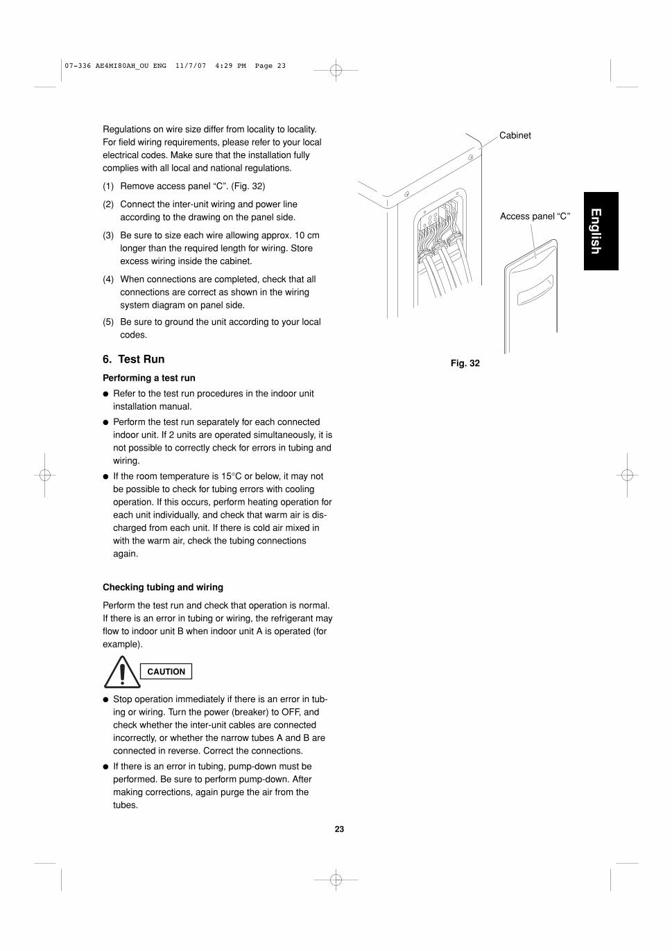
(1) Remove access panel “C”. (Fig. 32)
(2) Connect the inter-unit wiring and power lineaccording to the drawing on the panel side.
(3) Be sure to size each wire allowing approx. 10 cmlonger than the required length for wiring. Storeexcess wiring inside the cabinet.
(4) When connections are completed, check that all connections are correct as shown in the wiring system diagram on panel side.
(5) Be sure to ground the unit according to your localcodes.
Fig. 32
Access panel C
Cabinet
6. Test Run
Performing a test run
� Refer to the test run procedures in the indoor unitinstallation manual.
� Perform the test run separately for each connectedindoor unit. If 2 units are operated simultaneously, it isnot possible to correctly check for errors in tubing andwiring.
� If the room temperature is 15°C or below, it may notbe possible to check for tubing errors with coolingoperation. If this occurs, perform heating operation foreach unit individually, and check that warm air is dis-charged from each unit. If there is cold air mixed inwith the warm air, check the tubing connectionsagain.
Checking tubing and wiring
Perform the test run and check that operation is normal.If there is an error in tubing or wiring, the refrigerant mayflow to indoor unit B when indoor unit A is operated (forexample).
� Stop operation immediately if there is an error in tub-ing or wiring. Turn the power (breaker) to OFF, andcheck whether the inter-unit cables are connectedincorrectly, or whether the narrow tubes A and B areconnected in reverse. Correct the connections.
� If there is an error in tubing, pump-down must be performed. Be sure to perform pump-down. Aftermaking corrections, again purge the air from thetubes.
CAUTION
07-336 AE4MI80AH_OU ENG 11/7/07 4:29 PM Page 23

24
En
glis
h
7. Connecting a Home Automation device
The HA (white) 4P terminal is located on the indoor unit PCB. If a HA device will be used, connect it to this terminal.Also, refer to Section 9. ELECTRIC WIRING DIAGRAM in the outdoor unit installation manual.
8. Installation Check Sheet
The strength of the installation location is sufficient to support the Air Conditioner weight.
The indoor and outdoor units are installed level and vertically.
The power and voltage are as specified.
Inter-unit cables are securely fastened to the terminal board.
Inter-unit cables are securely fixed.
The power cord and inter-unit cables are not connected anywhere along their paths.
The ground wire is securely connected.
An air purge of the refrigerant circuit has been conducted.
A leak test of the tubing connections has been performed.
Thermal insulation has been applied to the tubing connections.
Drain connections are secure and water drains properly.
Putty has been used to close the hole in the wall.
All service valves are fully open.
Remote controller signals are being positively received.
07-336 AE4MI80AH_OU ENG 11/7/07 4:29 PM Page 24
21
21
21
21
BLKBLK
WHTWHT
WHTWHT
12
1 2 3 4
w
w
BLK
BLK
CO
MP
RE
SS
OR
TH
ER
MIS
TOR
(OLR)OVERLOAD RELAY
COMPRESSORMOTOR
WHT
RED
(2P) CONNECTOR
(2P) CONNECTOR
COMP
OLR0
OLR1
COIL/OUTDOOR
w wwU V W
21
21
3 3CM
(3P) CONNECTOR
FERRITECORE
WHTBLUBLUWHTWHT
RED(PNK) RED(PNK)
GRN/YEL
CR
S
1 21 2
3 43 4
BLK
BLK
YE
LY
EL
BLK
BLK
YE
LY
EL
CO
ILT
HE
RM
ISTO
R
OU
TD
OO
RT
HE
RM
ISTO
R
(4P
) C
ON
NE
CTO
RW
HT
1 2 3 4A-TH B-TH
1 21 2
3 43 4
YE
LY
EL
YE
LY
EL
YE
LY
EL
BLK
BLK
BLU
BLU
YE
LY
EL
AW
TH
ER
MIS
TOR
AN
TH
ER
MIS
TOR
(4P
) C
ON
NE
CTO
RR
ED
1 2 3 4
CN04 DCFM
FAN MOTOR
MV1
CONTROLLER
1 21 2
3 43 4
YE
LY
EL
YE
LY
EL
YE
LY
EL
YE
LY
EL
BW
TH
ER
MIS
TOR
BN
TH
ER
MIS
TOR
(4P
) C
ON
NE
CTO
RB
LU
(2P
) C
ON
NE
CTO
RB
LK
w w
2 12 1
DEF
DEF0DEF1
COILDEFROST VALVE
BLK
BLK
BLU
BLU
(2P
) C
ON
NE
CTO
RW
HT
(2P
) C
ON
NE
CTO
RW
HT
w w
2 12 1
2 12 1
RV
RV0RV1
w w w w w w
w
w
w
L1 E ACIN1
ACIN2
E-1E-2L2
COIL4WAY VALVE
REACTANCE
WH
TW
HT
WH
TW
HT
GR
N/Y
EL
GR
N/Y
EL
GR
N/Y
EL
25A
BLK
RED
BLU
WHT
S1-A
S1-B
REACTANCEBLK
WHT
WHT
BLK
BLK
TERMINALPLATE
A IN
DO
OR
UN
ITB
IND
OO
RU
NIT
PO
WE
RS
UP
PLY
TO IN
DO
OR
UN
IT
LN
GND
1 2 3 4 5 6 7 1 2 3 4 5
1 21 2
3 43 4
5 65 6
77 W
HT
BLU
(7P
) C
ON
NE
CTO
R
(5P
) C
ON
NE
CTO
R
FM
BLK
BLK
OR
G
GR
Y
WH
T
RE
D
RE
D
BLU
YE
L
YE
LB
LK
OR
G
GR
Y
RE
DY
EL
BLK
WH
T
RE
DB
LUY
EL
1 2 3 4 51 2 3 4 5
1 2 3 4 51 2 3 4 5
MV1
MAGNETIC COIL
MV01 2 3 4 5
RE
D
(5P
) C
ON
NE
CTO
R
BLK
OR
G
GR
Y
RE
DY
EL
BLK
OR
G
GR
Y
RE
DY
EL
1 2 3 4 51 2 3 4 5
1 2 3 4 51 2 3 4 5
MV0
MAGNETIC COIL
1
2
3
4
5
6
7
8
8FA-2-5257-56900-2
25
En
glish
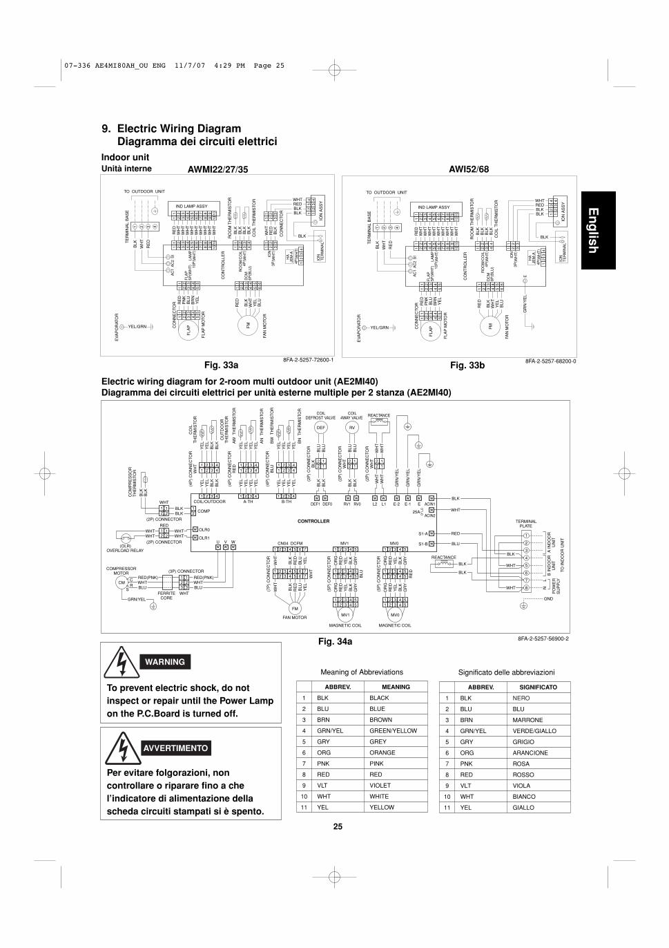
9. Electric Wiring DiagramDiagramma dei circuiti elettrici
EV
AP
OR
ATO
R
TE
RM
INA
L B
AS
E
WH
T
BLK
RE
D
1 2 3 4
YEL/GRN
LAM
P10
P( W
HT
)
FLA
P5P
(WH
T)
FLA
PCO
NN
EC
TOR
FLA
P M
OTO
R
RE
DP
NK
BLU
BR
NY
EL
1 2 3 4 5
1 2 3 4 5
1 2 3 4 5
1 2 3 4 5
AC
1A
C2
SI
WH
TR
ED
WH
TW
HT
WH
TW
HT
WH
TW
HT
WH
TW
HT
1 2 3 4 5 6 7 8 9 10
1 2 3 4 5 6 7 8 9 10
1 2 3 4 5 6 7 8 9 10
1 2 3 4 5 6 7 8 9 10
IND LAMP ASSY
RO
OM
/CO
IL4P
( WH
T)
DC
M6P
(BLU
)
CO
NT
RO
LLE
R
FM
FAN
MO
TOR
RE
D1 2 3 4 5 6
1 2 3 4 5 6
WH
TB
LK
YE
LB
LU
RO
OM
TH
ER
MIS
TOR
BLK
BLK
BLK
BLK
1 2 3 4
1 2 3 4C
OIL
TH
ER
MIS
TOR
ION
3P( W
HT
)
HA
JEM
-A
1 2 3
1 2 3
1 2 3
1 2 3
4P( W
HT
)1
24
BLK
3
BLKBLKREDWHT
12
34
12
34
ION
AS
SY
ION
TE
RM
INA
L
TO OUTDOOR UNIT
WH
TR
ED
BLK
CO
NN
EC
TOR
8FA-2-5257-72600-1
LAM
P10
P( W
HT
)
FLA
P5P
(WH
T)
FLA
PCO
NN
EC
TOR
FLA
P M
OTO
R
RE
DP
NK
BLU
BR
NY
EL
1 2 3 4 5
1 2 3 4 5
1 2 3 4 5
1 2 3 4 5
AC
1A
C2
SI
WH
TR
ED
WH
TW
HT
WH
TW
HT
WH
TW
HT
WH
TW
HT
1 2 3 4 5 6 7 8 9 10
1 2 3 4 5 6 7 8 9 10
1 2 3 4 5 6 7 8 9 10
1 2 3 4 5 6 7 8 9 10
IND LAMP ASSY
RO
OM
/CO
IL4P
( WH
T)
DC
M6P
(BLU
)
CO
NT
RO
LLE
R
FM
FAN
MO
TOR
RE
D1 2 3 4 5 6
1 2 3 4 5 6
WH
TB
LK
YE
LB
LU
GR
N/Y
EL
E
RO
OM
TH
ER
MIS
TOR
BLK
BLK
BLK
BLK
1 2 3 4
1 2 3 4C
OIL
TH
ER
MIS
TOR
ION
3P( W
HT
)
HA
JEM
-A
1 2 3
1 2 3
4P( W
HT
)1
24
BLK
3
BLKBLKREDWHT
12
34
12
34
ION
AS
SY
ION
TE
RM
INA
LTE
RM
INA
L B
AS
E
WH
T
BLK
RE
D
1 2 3 4
EV
AP
OR
ATO
R
YEL/GRN
TO OUTDOOR UNIT
8FA-2-5257-68200-0
AWMI22/27/35 AWI52/68
Fig. 33a Fig. 33b
Meaning of Abbreviations
1
2
3
4
5
6
7
8
9
10
11
ABBREV.
BLK
BLU
BRN
GRN/YEL
GRY
ORG
PNK
RED
VLT
WHT
YEL
MEANING
BLACK
BLUE
BROWN
GREEN/YELLOW
GREY
ORANGE
PINK
RED
VIOLET
WHITE
YELLOW
Electric wiring diagram for 2-room multi outdoor unit (AE2MI40)Diagramma dei circuiti elettrici per unità esterne multiple per 2 stanza (AE2MI40)
To prevent electric shock, do notinspect or repair until the Power Lampon the P.C.Board is turned off.
WARNING
Indoor unitUnità interne
Significato delle abbreviazioni
1
2
3
4
5
6
7
8
9
01
11
ABBREV.
KLB
ULB
NRB
LEY/NRG
YRG
GRO
KNP
DER
TLV
THW
LEY
SIGNIFICATO
NERO
BLU
MARRONE
VERDE/GIALLO
GRIGIO
ARANCIONE
ROSA
ROSSO
VIOLA
BIANCO
GIALLO
Per evitare folgorazioni, non controllare o riparare fino a che l’indicatore di alimentazione della scheda circuiti stampati si è spento.
AVVERTIMENTO
Fig. 34a
07-336 AE4MI80AH_OU ENG 11/7/07 4:29 PM Page 25

26
En
glis
h
WH
TW
HT
L2 L1
WH
TW
HT
WH
T2P
-CO
NN
EC
TOR
2 12 1
REACTANCE
CO
ILT
HE
RM
ISTO
RC
OM
P
COIL/OUTDOOR A-TH B-TH
CO
MP
RE
SS
OR
TH
ER
MIS
TOR O
UT
DO
OR
TH
ER
MIS
TOR
AW
TH
ER
MIS
TOR
W W
DEF1 DEF0W W
RV1 RV0
DEF
COILDEFROST VALVE
2 12 1
RV
COIL4WAY VALVE
AN
TH
ER
MIS
TOR
BN
TH
ER
MIS
TOR
BW
TH
ER
MIS
TOR
BLK
2P-C
ON
NE
CTO
R
WH
T2P
-CO
NN
EC
TOR
2 12 1
YE
LY
EL
YE
LY
EL
YE
LY
EL
YE
LY
EL
BLK
BLK
BLU
BLU
BLK
BLK
BLU
BLU
YE
LY
EL
BLK
BLK
BLK
BLK
1 2 3 41 2 3 4
1 2 3 41 2 3 4
1 2 3 41 2 3 4
1122
W W
ACIN1W BLK
WHT
RED
25AACIN2
W
W
W
S1-A
S1-B BLU
BLK
WHT
WHT
BLK
BLK
REACTANCE
1
2
3
4
5
6
7
8
GND
PO
WE
RS
UP
PLY
B IN
DO
OR
UN
ITA
IND
OO
RU
NIT
TO IN
DO
OR
UN
IT
CONTROLLERW
W
WHTWHT
WHTWHT 2 2
1 1
2P-CONNECTOR
3P-C
ON
NE
CTO
R
W
UW
VW
WDCFMCN04
1 2 31 2 3
FE
RR
ITE
CO
REW
HT
BLU
RE
D( P
NK
)W
HT
BLU
RE
D( P
NK
)
CM GRN/YEL
COMPRESSORMOTOR
FM
1 2 3 41 2 3 4
5 6 75 6 7
1 2 3 4 5 6 7
RE
D
BLU
BR
NW
HT
OR
G
RE
D
BLU
BR
NW
HT
OR
G
1 2 3 41 2 3 4
55
1 2 3 41 2 3 4
55
RE
DO
RG
BL
KY
EL
GR
Y
BL
KY
EL
GR
YMV1
MAGNETIC COIL
MV1
MAGNETIC COIL
MV01 2 3 41 2 3 4
55
1 2 3 41 2 3 4
55
RE
DO
RG
MV0 NL
(OLR)OVERLOAD RELAY
FAN MOTORS/U C/W
R/V
8FA-2-5257-84200-0
WH
T
RED
W W
HEATER1 HEATER0
HEATERCRANKCASE
2211
WHT2P-CONNECTOR
WH
TW
HT
WH
T
WH
T
OLR1
OLR0
E-2W
GR
N/Y
EL
EW
GR
N/Y
EL
E-1W
GR
N/Y
EL
TERMINALPLATE
FERRITECORE
Fig. 34b
WH
TW
HT
L2 L1
WH
TW
HT
WH
T2P
-CO
NN
EC
TOR
2 12 1
REACTANCE
W W
HEATER1 HEATER0
CRANKCASEHEATER
CO
ILT
HE
RM
ISTO
RC
OM
P
COIL/OUTDOOR A-TH B-TH
CO
MP
RE
SS
OR
TH
ER
MIS
TOR
OU
TD
OO
RT
HE
RM
ISTO
R
AW
TH
ER
MIS
TOR
W W
DEF1 DEF0W W
RV1 RV0
DEF
COILDEFROST VALVE
2 12 1
RV
COIL4WAY VALVE
AN
TH
ER
MIS
TOR
BN
TH
ER
MIS
TOR
BW
TH
ER
MIS
TOR
BLK
2P-C
ON
NE
CTO
R
WH
T2P
-CO
NN
EC
TOR
1122
2P-CONNECTORWHT
2 12 1
YE
LY
EL
YE
LY
EL
YE
LY
EL
YE
LY
EL
BLK
BLK
BLU
BLU
BLK
BLK
BLU
BLU
WH
TW
HT
WH
T
WH
T
YE
LY
EL
BLK
BLK
BLK
BLK
1 2 3 41 2 3 4
1 2 3 41 2 3 4
1 2 3 41 2 3 4
1122
W W
E-2W
GR
N/Y
EL
ACIN1W BLK
WHT
RED
25AACIN2
W
W
W
S1-A
S1-B BLU
1
2
3
4
5
6
7
8
9
11
12
GND
PO
WE
RS
UP
PLY
B IN
DO
OR
UN
ITC
IND
OO
RU
NIT
A IN
DO
OR
UN
IT
TO IN
DO
OR
UN
IT
CONTROLLER
WHTWHT
WHTWHT2P-CONNECTOR
RED
3P-C
ON
NE
CTO
R
U
V
W CNO4 DCFM
1 2 31 2 3
FERRITECORE
WH
TB
LUW
HT
BLU
RE
D(P
NK
)
CM
GR
N/Y
EL
COMPRESSORMOTOR
FM
1 2 3 41 2 3 4
5 6 75 6 7
1 2 3 4 5 6 7
RE
D
BLU
BR
NW
HT
OR
G
RE
D
BLU
BR
NW
HT
OR
G
1 2 3 41 2 3 4
55
1 2 3 41 2 3 4
55
RE
DO
RG
MV1
MAGNETIC COIL
MV1
MAGNETIC COIL
MV01 2 3 41 2 3 4
55
1 2 3 41 2 3 4
55
RE
DO
RG
MV0
NL
OVERLOAD RELAY(OLR)
FAN MOTOR
S/U C/W
R/V
W
GR
N/Y
EL
EW
GR
N/Y
EL
GND
TERMINALPLATE
BLK
BLK
WHTWHT
WHT
BLK
WHT
REACTANCE
BLK
BLK
BRN
WH
TF
ER
RIT
EC
OR
E
2211
OLR0
OLR1
RE
D
WH
T
BLU
RE
D
88
8
BLU
BLK
BLK
WH
T
CNO3
KS2321 3 4 5 6 7
1 2 3 41 2 3 4
5 6 75 6 7
CNO2
KS2221 3 4 5 6
1 2 3 41 2 3 4
5 65 6
RE
D
WH
T
BLU
BLK
BLK
WH
T
RE
DB
LU
BLK
WH
T
WH
T
1 2 3 41 2 3 4
CNO1
KS1021 3 4 W
W
SICOM2
SICOM2
SI-CW
SI-DW
RE
DO
RG
1 2 3 41 2 3 4
55
MV2
MAGNETIC COIL
1 2 3 41 2 3 4
55
MV2
RE
DO
RG
1 2 3 41 2 3 4
55
MV3
MAGNETIC COIL
1 2 3 41 2 4
55
MV31 2 3 41 2 3 4
C-TH
YE
L
YE
LY
EL
YE
L
CW
TH
ER
MIS
TOR
CN
TH
ER
MIS
TOR
W
W
W
W
W
1
2
3
10
D IN
DO
OR
UN
IT
GRY
1 2 3 41 2 3 4
D-TH
YE
L
YE
LY
EL
YE
L
DW
TH
ER
MIS
TOR
DN
TH
ER
MIS
TOR
3
E-1
RE
D(P
NK
)
BLK
YE
L
GR
Y
BLK
YE
L
GR
Y
BLK
YE
L
GR
Y
BLK
YE
L
GR
Y
8FA-2-5257-57100-0Fig. 34c
WH
TW
HT
L2 L1
WH
TW
HT
WH
T( 2
P)
CO
NN
EC
TO
R
2 12 1
REACTANCE
W W
HEATER1 HEATER0
CRANKCASEHEATER
CO
ILT
HE
RM
IST
OR
CO
MP
COIL/OUTDOOR A-TH B-TH
CO
MP
RE
SS
OR
TH
ER
MIS
TO
R
OU
TD
OO
RT
HE
RM
IST
OR
AW
TH
ER
MIS
TO
R
W W
DEF1 DEF0W W
RV1 RV0
DEF
COILDEFROST VALVE
2 12 1
RV
COIL4WAY VALVE
AN
TH
ER
MIS
TO
R
BN
TH
ER
MIS
TO
R
BW
TH
ER
MIS
TO
R
BLK
( 2P
) C
ON
NE
CT
OR
WH
T( 2
P)
CO
NN
EC
TO
R
1122
(2P) CONNECTORWHT
2 12 1
YE
LY
EL
YE
LY
EL
YE
LY
EL
YE
LY
EL
BLK
BLK
BLU
BLU
BLK
BLK
BLU
BLU
WH
TW
HT
WH
T
WH
T
YE
LY
EL
BLK
BLK
BLK
BLK
1 2 3 41 2 3 4
1 2 3 41 2 3 4
1 2 3 41 2 3 4
1122
W W
E-2W
GR
N/Y
EL
ACIN1W BLK
WHT
RED
25AACIN2
W
W
W
S1-A
S1-B BLU
1
2
3
4
5
6
7
8
9
11
12
GND
PO
WE
RS
UP
PLY
B IN
DO
OR
UN
ITC
IND
OO
RU
NIT
A IN
DO
OR
UN
IT
TO
IND
OO
R U
NIT
CONTROLLER
WHTWHT
WHTWHT(2P) CONNECTOR
RED
(3P
) C
ON
NE
CT
OR
U
V
W CNO4 DCFM
1 2 31 2 3
FERRITECORE
WH
TB
LUW
HT
BLU
RE
D(P
NK
)
CM
GR
N/Y
EL
COMPRESSORMOTOR
FM
1 2 3 41 2 3 4
5 6 75 6 7
1 2 3 4 5 6 7
RE
D
BLU
BR
NW
HT
OR
G
RE
D
BLU
BR
NW
HT
OR
G
1 2 3 41 2 3 4
55
1 2 3 41 2 3 4
55
RE
DO
RG
MV1
MAGNETIC COIL
MV1
MAGNETIC COIL
MV01 2 3 41 2 3 4
55
1 2 3 41 2 3 4
55
RE
DO
RG
MV0
NL
OVERLOAD RELAY(OLR)
FAN MOTOR
S/U C/W
R/V
W
GR
N/Y
EL
EW
GR
N/Y
EL
GND
TERMINALPLATE
BLK
BLK
WHTWHT
WHT
BLK
WHT
REACTANCE
BLK
BLK
BRN
WH
TF
ER
RIT
EC
OR
E
2211
OLR0
OLR1
RE
D
WH
T
BLU
RE
D
88
8
BLU
BLK
BLK
WH
T
CNO3
KS2321 3 4 5 6 7
1 2 3 41 2 3 4
5 6 75 6 7
CNO2
KS2221 3 4 5 6
1 2 3 41 2 3 4
5 65 6
RE
D
WH
T
BLU
BLK
BLK
WH
T
RE
DB
LU
BLK
WH
T
WH
T
1 2 3 41 2 3 4
CNO1
KS1021 3 4 W
W
SICOM2
SICOM2
SI-CW
SI-DW
RE
DO
RG
1 2 3 41 2 3 4
55
MV2
MAGNETIC COIL
1 2 3 41 2 3 4
55
MV2
RE
DO
RG
1 2 3 41 2 3 4
55
MV3
MAGNETIC COIL
1 2 3 41 2 4
55
MV31 2 3 41 2 3 4
C-TH
YE
L
YE
LY
EL
YE
L
CW
TH
ER
MIS
TO
R
CN
TH
ER
MIS
TO
R
W
W
W
W
W
1
2
3
10
D IN
DO
OR
UN
IT
GRY
1 2 3 41 2 3 4
D-TH
YE
L
YE
LY
EL
YE
L
DW
TH
ER
MIS
TO
R
DN
TH
ER
MIS
TO
R
3
E-1
RE
D(P
NK
)
BLK
YE
L
GR
Y
BLK
YE
L
GR
Y
BLK
YE
L
GR
Y
BLK
YE
L
GR
Y
8FA-2-5257-89000-0
FE
RR
ITE
CO
RE
( 7P
) C
ON
NE
CT
OR
WH
T
Fig. 34d
Electric wiring diagram for 4-room multi outdoor unit (AE4MI80)Diagramma dei circuiti elettrici per unità esterne multiple per 4 stanza (AE4MI80)
Meaning of Abbreviations
1
2
3
4
5
6
7
8
9
10
11
ABBREV.
BLK
BLU
BRN
GRN/YEL
GRY
ORG
PNK
RED
VLT
WHT
YEL
MEANING
BLACK
BLUE
BROWN
GREEN/YELLOW
GREY
ORANGE
PINK
RED
VIOLET
WHITE
YELLOW
Significato delle abbreviazioni
1
2
3
4
5
6
7
8
9
01
11
ABBREV.
KLB
ULB
NRB
LEY/NRG
YRG
GRO
KNP
DER
TLV
THW
LEY
SIGNIFICATO
NERO
BLU
MARRONE
VERDE/GIALLO
GRIGIO
ARANCIONE
ROSA
ROSSO
VIOLA
BIANCO
GIALLO
Electric wiring diagram for 4-room multi outdoor unit (AE3MI68)Diagramma dei circuiti elettrici per unità esterne multiple per 4 stanza (AE3MI68)
Electric wiring diagram for 2-room multi outdoor unit (AE2MI56)Diagramma dei circuiti elettrici per unità esterne multiple per 2 stanza (AE2MI56)
07-336 AE4MI80AH_OU ENG 11/7/07 4:29 PM Page 26

Via Varese, 90 - 21013 Gallarate (VA) - Italy
http://www.argoclima.comTel. +39 0331 755111 - Fax +39 0331 776240
07-337 AE4MI80AH_OU ITA 11/7/07 4:41 PM Page 26