installation instructions ties - carid.com · route the short wire harness through the bottom...
TRANSCRIPT
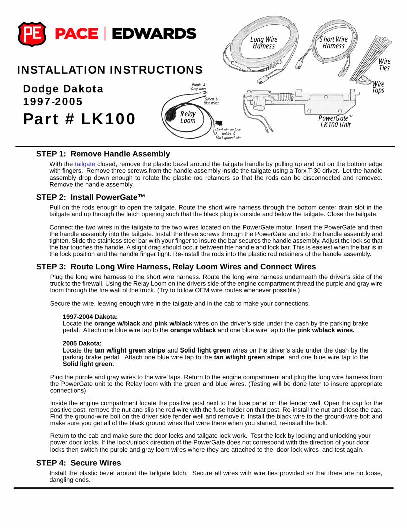
Dodge Dakota1997-2005
Part # LK100
STEP 1: Remove Handle AssemblyWith the tailgate closed, remove the plastic bezel around the tailgate handle by pulling up and out on the bottom edge with fi ngers. Remove three screws from the handle assembly inside the tailgate using a Torx T-30 driver. Let the handle assembly drop down enough to rotate the plastic rod retainers so that the rods can be disconnected and removed. Remove the handle assembly.
STEP 2: Install PowerGate™Pull on the rods enough to open the tailgate. Route the short wire harness through the bottom center drain slot in the tailgate and up through the latch opening such that the black plug is outside and below the tailgate. Close the tailgate.
Connect the two wires in the tailgate to the two wires located on the PowerGate motor. Insert the PowerGate and then the handle assembly into the tailgate. Install the three screws through the PowerGate and into the handle assembly and tighten. Slide the stainless steel bar with your fi nger to insure the bar secures the handle assembly. Adjust the lock so that the bar touches the handle. A slight drag should occur between hte handle and lock bar. This is easiest when the bar is in the lock position and the handle fi nger tight. Re-install the rods into the plastic rod retainers of the handle assembly.
STEP 3: Route Long Wire Harness, Relay Loom Wires and Connect WiresPlug the long wire harness to the short wire harness. Route the long wire harness underneath the driver’s side of the truck to the fi rewall. Using the Relay Loom on the drivers side of the engine compartment thread the purple and gray wire loom through the fi re wall of the truck. (Try to follow OEM wire routes whenever possible.)
Secure the wire, leaving enough wire in the tailgate and in the cab to make your connections.
1997-2004 Dakota:Locate the orange w/black and pink w/black wires on the driver’s side under the dash by the parking brake pedal. Attach one blue wire tap to the orange w/black and one blue wire tap to the pink w/black wires.
2005 Dakota: Locate the tan w/light green stripe and Solid light green wires on the driver’s side under the dash by the parking brake pedal. Attach one blue wire tap to the tan w/light green stripe and one blue wire tap to the Solid light green.
Plug the purple and gray wires to the wire taps. Return to the engine compartment and plug the long wire harness from the PowerGate unit to the Relay loom with the green and blue wires. (Testing will be done later to insure appropriate connections)
Inside the engine compartment locate the positive post next to the fuse panel on the fender well. Open the cap for the positive post, remove the nut and slip the red wire with the fuse holder on that post. Re-install the nut and close the cap. Find the ground-wire bolt on the driver side fender well and remove it. Install the black wire to the ground-wire bolt and make sure you get all of the black ground wires that were there when you started, re-install the bolt.
Return to the cab and make sure the door locks and tailgate lock work. Test the lock by locking and unlocking your power door locks. If the lock/unlock direction of the PowerGate does not correspond with the direction of your door locks then switch the purple and gray loom wires where they are attached to the door lock wires and test again.
STEP 4: Secure WiresInstall the plastic bezel around the tailgate latch. Secure all wires with wire ties provided so that there are no loose, dangling ends.
Long Wire Harness
Short Wire Harness
Wire Ties
Wire Taps
PowerGateTM LK100 Unit
INSTALLATION INSTRUCTIONS
Relay Loom
Purple & Gray wires
Green & Blue wires
Red wire w/ fuse holder &
black ground-wire

Dodge RAM - 1994-2001Dodge RAM 2500/3500 - 2002
Part # LK150
Long Wire Harness
Short Wire Harness
Wire Ties
Wire Taps
PowerGateTM LK150 Unit
INSTALLATION INSTRUCTIONS
STEP 1: Remove Handle AssemblyWith the tailgate closed, remove the plastic bezel around the tailgate handle by pulling up and out on the bottom edge with fi ngers. Open the tailgate -- DO NOT close the tailgate until installation is complete. Remove the three screws that hold handle assembly using a Torx T-30 driver. Let the handle assembly drop down enough to rotate the plastic rod retainers so that the rods can be disconnected and removed. Remove the handle assembly.
STEP 2: Install PowerGate™Starting at the drain hole in the bottom of the tailgate, route the short wire harness through the latch opening so that the black plug is outside and below the tailgate. Connect the two wires in the tailgate to the two wires located on the PowerGate motor. Insert the PowerGate and the handle assembly into the tailgate. Install the three screws through the PowerGate and into the handle assembly and tighten. Slide the stainless steel bolt with your fi nger to insure the bolt secures the handle assembly. Adjust if necessary. Install the rods into the plastic rod retainers of the handle assembly.
STEP 3: Route Long Wire Harness, Relay Loom Wires and Connect WiresPlug the long wire harness to the short wire harness. Route the long wire harness underneath the driver’s side of the truck to the fi rewall.
Using the Relay Loom on the drivers side of the engine compartment thread the purple and gray wire loom through the fi re wall of the truck. (Try to follow OEM wire routes whenever possible.)
For 1998 Dodge Ram only: Locate the orange w/black and pink w/black wires or the orange w/violet and pink w/violet wires behind the driver’s side kick panel just forward of the driver’s side door. Either of these color schemes may be used.
For all other models: Locate the orange w/brown and pink w/black wires behind the driver’s side kick panel just forward of the driver’s side door.
Install one blue wiretap on each of the two wires indicated above. Plug the purple and gray wires to the wire taps. Return to the engine compartment and plug the long wire harness from the PowerGate unit to the Relay loom with the green and blue wires. (Testing will be done later to insure appropriate connections)
Inside the engine compartment locate the positive post next to the fuse panel on the fender well. Open the cap for the positive post, remove the nut and slip the red wire with the fuse holder on that post. Re-install the nut and close the cap. Find the ground-wire bolt on the driver side fender well and remove it. Install the black wire to the ground-wire bolt and make sure you get all of the black ground wires that were there when you started, re-install the bolt.
Return to the cab and make sure the door locks and tailgate lock work. Test the lock by locking and unlocking your power door locks. If the lock/unlock direction of the PowerGate does not correspond with the direction of your door locks then switch the purple and gray loom wires where they are attached to the door lock wires and test again.
STEP 4: Secure WiresInstall the plastic bezel around the tailgate latch. Secure all wires with wire ties provided so that there are no loose, dangling ends.
Relay Loom
Purple & Gray wires
Green & Blue wires
Red wire w/ fuse holder &
black ground-wire

Dodge RAM 1500 -2002Dodge RAM -2003-2006
Part # LK160
Long Wire Harness
Short Wire Harness
Wire Ties
Wire Taps
PowerGateTM LK160 Unit
INSTALLATION INSTRUCTIONS
STEP 1: Install PowerGate™With the tailgate open, remove the screws from the tailgate access panel using a #30 Torx driver. Remove the two (10mm) nuts that hold the handle assembly. Install PowerGate™ lock through the tailgate opening and over the studs of the handle assembly. Replace 10mm nuts and tighten. Slide lock bolt with your fi ngers to see that there is no interference and that the bolt locks the handle. Adjust if necessary.
STEP 2: Route Wire Harness & Relay Loom WiresRoute the short wire harness through the drain hole in the bottom of tailgate and connect it to PowerGate. Plug the long wire harness to the short wire harness. Route the long wire harness underneath the driver’s side of the truck to the fi rewall.
Using the Relay Loom on the drivers side of the engine compartment thread the purple and gray wire loom through the fi re wall of the truck. (Try to follow OEM wire routes whenever possible.)
STEP 3: Locate and Connect Wires
2002 Ram 1500 & 2003 RAMLocate the tan w/pink and solid blue wires on the driver’s side under the dash by the parking brake pedal.
2004-2006 RAMLocate the Tan w/light green and Lime Green wires on the driver’s side under the dash by the parking brake pedal.
Install one blue wiretap on each of the two wires indicated above. Plug the purple and gray wires to the wire taps. Return to the engine compartment and plug the long wire harness from the PowerGate unit to the Relay loom with the green and blue wires. (Testing will be done later to insure appropriate connections)
Inside the engine compartment locate the positive post next to the fuse panel on the fender well. Open the cap for the positive post, remove the nut and slip the red wire with the fuse holder on that post. Re-install the nut and close the cap. Find the ground-wire bolt on the driver side fender well and remove it. Install the black wire to the ground-wire bolt and make sure you get all of the black ground wires that were there when you started, re-install the bolt.
Return to the cab and make sure the door locks and tailgate lock work. Test the lock by locking and unlocking your power door locks. If the lock/unlock direction of the PowerGate does not correspond with the direction of your door locks then switch the purple and gray loom wires where they are attached to the door lock wires and test again.
STEP 4: Secure WiresInstall tailgate access panel. Secure all wires with wire ties provided so that there are no loose, dangling ends.
Relay Loom
Purple & Gray wires
Green & Blue wires
Red wire w/ fuse holder &
black ground-wire

INSTALLATION INSTRUCTIONSLK 170
STEP 1 : INSTALL POWERGATE!! NOTE: BE SURE TO PROTECT ALL PAINTED SURFACES OF THE TRUCK !!
With the tailgate open, remove the screws from the tailgate access panel using a #10 Torx driver. Remove the two (8mm) nuts that hold the handle assembly. Install PowerGate™ lock through the tailgate opening and over the studs of the handle assembly. Replace 8mm nuts and tighten. Slide lock bolt with your fi ngers to see that there is no interference and that the bolt locks the handle. Adjust if necessary.
STEP 2 : ROUTE WIRE HARNESS & RELAY LOOM WIRESRoute the short wire harness through the drain hole in the bottom of tailgate and connect it to PowerGate. Plug the long wire harness to the short wire harness. Route the long wire harness underneath the driver’s side of the truck to the fi rewall.
Using the Relay Loom on the drivers side of the engine compartment thread the purple and gray wire loom through the fi re wall of the truck. (Try to follow OEM wire routes whenever possible.)
TOOLS REQUIRED:#10 Torx bit 8mm Socket 6” extension or nut driver is helpful
PACKAGE CONTENTS:
SHORT WIRE HARNESS LONG WIRE
HARNESS
WIRE TIES
POWERGATE ACTUATOR
WIRE T-TAPS
WIRE RELAY HARNESS
STEP 3 : LOCATE & CONNECT WIRES2009 RAM 1500Locate the TAN/ GREEN and TAN/ WHITE wires on the driver’s side under the dash by the brake pedal. The wires are in the bigger of the 3 harnesses.
Install one blue wiretap on each of the two wires indicated above. Plug the purple and gray wires to the wire taps. Return to the engine compartment and plug the long wire harness from the PowerGate unit to the Relay loom with the green and blue wires. (Testing will be done later to insure appropriate connections) (continued on next page...)
• 2009 DODGE RAM 1500 •

STEP 4 : SECURE WIRESInstall tailgate access panel. Secure all wires with wire ties provided so that there are no loose, dangling ends.
STEP 3 : LOCATE & CONNECT WIRES (CONTINUED)Inside the engine compartment locate the positive post next to the fuse panel on the fender well. Open the cap for the positive post, remove the nut and slip the red wire with the fuse holder on that post. Re-install the nut and close the cap. Find the ground-wire bolt on the driver side fender well and remove it. Install the black wire to the ground-wire bolt and make sure you get all of the black ground wires that were there when you started, re-install the bolt.
Return to the cab and make sure the door locks and tailgate lock work. Test the lock by locking and unlocking your power door locks. If the lock/unlock direction of the PowerGate does not correspond with the direction of your door locks then switch the purple and gray loom wires where they are attached to the door lock wires and test again.
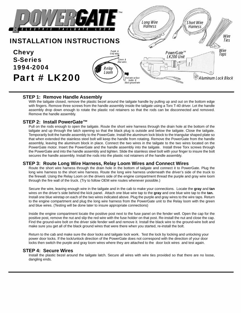
ChevyS-Series1994-2004
Part # LK200
Long Wire Harness
Short Wire Harness
Wire Ties
Wire TapsPowerGateTM
LK200 Unit
INSTALLATION INSTRUCTIONS
STEP 1: Remove Handle AssemblyWith the tailgate closed, remove the plastic bezel around the tailgate handle by pulling up and out on the bottom edge with fi ngers. Remove three screws from the handle assembly inside the tailgate using a Torx T-40 driver. Let the handle assembly drop down enough to rotate the plastic rod retainers so that the rods can be disconnected and removed. Remove the handle assembly.
STEP 2: Install PowerGate™Pull on the rods enough to open the tailgate. Route the short wire harness through the drain hole at the bottom of the tailgate and up through the latch opening so that the black plug is outside and below the tailgate. Close the tailgate. Temporarily bolt the handle assembly to the PowerGate. Install the aluminum lock block to the triangular shaped plate so that when extended the stainless steel bolt will keep the handle from rotating. Remove the PowerGate from the handle assembly, leaving the aluminum block in place. Connect the two wires in the tailgate to the two wires located on the PowerGate motor. Insert the PowerGate and the handle assembly into the tailgate. Install three Torx screws through the PowerGate and into the handle assembly and tighten. Slide the stainless steel bolt with your fi nger to insure the bolt secures the handle assembly. Install the rods into the plastic rod retainers of the handle assembly.
STEP 3: Route Long Wire Harness, Relay Loom Wires and Connect WiresRoute the short wire harness through the drain hole in the bottom of tailgate and connect it to PowerGate. Plug the long wire harness to the short wire harness. Route the long wire harness underneath the driver’s side of the truck to the fi rewall. Using the Relay Loom on the drivers side of the engine compartment thread the purple and gray wire loom through the fi re wall of the truck. (Try to follow OEM wire routes whenever possible.)
Secure the wire, leaving enough wire in the tailgate and in the cab to make your connections. Locate the gray and tan wires on the driver’s side behind the kick panel. Attach one blue wire tap to the gray and one blue wire tap to the tan. Install one blue wiretap on each of the two wires indicated above. Plug the purple and gray wires to the wire taps. Return to the engine compartment and plug the long wire harness from the PowerGate unit to the Relay loom with the green and blue wires. (Testing will be done later to insure appropriate connections)
Inside the engine compartment locate the positive post next to the fuse panel on the fender well. Open the cap for the positive post, remove the nut and slip the red wire with the fuse holder on that post. Re-install the nut and close the cap. Find the ground-wire bolt on the driver side fender well and remove it. Install the black wire to the ground-wire bolt and make sure you get all of the black ground wires that were there when you started, re-install the bolt.
Return to the cab and make sure the door locks and tailgate lock work. Test the lock by locking and unlocking your power door locks. If the lock/unlock direction of the PowerGate does not correspond with the direction of your door locks then switch the purple and gray loom wires where they are attached to the door lock wires and test again.
STEP 4: Secure WiresInstall the plastic bezel around the tailgate latch. Secure all wires with wire ties provided so that there are no loose, dangling ends.
Aluminum Lock Block
Relay Loom
Purple & Gray wires
Green & Blue wires
Red wire w/ fuse holder &
black ground-wire
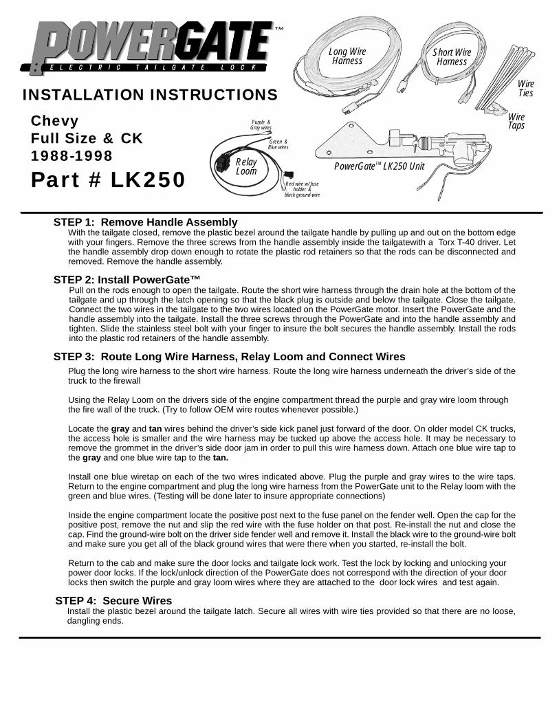
ChevyFull Size & CK1988-1998
Part # LK250
Long Wire Harness
Short Wire Harness
Wire Ties
Wire Taps
PowerGateTM LK250 Unit
INSTALLATION INSTRUCTIONS
STEP 1: Remove Handle AssemblyWith the tailgate closed, remove the plastic bezel around the tailgate handle by pulling up and out on the bottom edge with your fi ngers. Remove the three screws from the handle assembly inside the tailgatewith a Torx T-40 driver. Let the handle assembly drop down enough to rotate the plastic rod retainers so that the rods can be disconnected and removed. Remove the handle assembly.
STEP 2: Install PowerGate™Pull on the rods enough to open the tailgate. Route the short wire harness through the drain hole at the bottom of the tailgate and up through the latch opening so that the black plug is outside and below the tailgate. Close the tailgate. Connect the two wires in the tailgate to the two wires located on the PowerGate motor. Insert the PowerGate and the handle assembly into the tailgate. Install the three screws through the PowerGate and into the handle assembly and tighten. Slide the stainless steel bolt with your fi nger to insure the bolt secures the handle assembly. Install the rods into the plastic rod retainers of the handle assembly.
STEP 3: Route Long Wire Harness, Relay Loom and Connect WiresPlug the long wire harness to the short wire harness. Route the long wire harness underneath the driver’s side of the truck to the fi rewall
Using the Relay Loom on the drivers side of the engine compartment thread the purple and gray wire loom through the fi re wall of the truck. (Try to follow OEM wire routes whenever possible.)
Locate the gray and tan wires behind the driver’s side kick panel just forward of the door. On older model CK trucks, the access hole is smaller and the wire harness may be tucked up above the access hole. It may be necessary to remove the grommet in the driver’s side door jam in order to pull this wire harness down. Attach one blue wire tap to the gray and one blue wire tap to the tan.
Install one blue wiretap on each of the two wires indicated above. Plug the purple and gray wires to the wire taps. Return to the engine compartment and plug the long wire harness from the PowerGate unit to the Relay loom with the green and blue wires. (Testing will be done later to insure appropriate connections)
Inside the engine compartment locate the positive post next to the fuse panel on the fender well. Open the cap for the positive post, remove the nut and slip the red wire with the fuse holder on that post. Re-install the nut and close the cap. Find the ground-wire bolt on the driver side fender well and remove it. Install the black wire to the ground-wire bolt and make sure you get all of the black ground wires that were there when you started, re-install the bolt.
Return to the cab and make sure the door locks and tailgate lock work. Test the lock by locking and unlocking your power door locks. If the lock/unlock direction of the PowerGate does not correspond with the direction of your door locks then switch the purple and gray loom wires where they are attached to the door lock wires and test again.
STEP 4: Secure WiresInstall the plastic bezel around the tailgate latch. Secure all wires with wire ties provided so that there are no loose, dangling ends.
Relay Loom
Purple & Gray wires
Green & Blue wires
Red wire w/ fuse holder &
black ground-wire

Chevy / GMC Full Size1999-2006
Part # LK270
STEP 1: Remove Handle AssemblyWith the tailgate closed, remove the plastic bezel around the tailgate handle by pulling down and out on the top edge with fi ngers. Remove three 13 mm bolts from the handle assembly inside the tailgate. Let the handle assembly drop down enough to rotate the plastic rod retainers so that the rods can be disconnected and removed. Remove the handle assembly.
STEP 2: Install PowerGate™Pull on the rods enough to open the tailgate. Route the short wire harness through the drain hole at the bottom of the tailgate and up through the latch opening such that the black plug is outside and below the tailgate. Close the tailgate. Connect the two wires in the tailgate to the two wires located on the PowerGate motor. Put the PowerGate and the handle assembly into the tailgate. The lock plate assembly is mounted under the handle. The lock should be assembled in the lock position. Some minor right-or-left adjustment of the lock bar may be necessary to accommodate slight differences in tailgates. Re-Install the three screws through the PowerGate™ and into the handle assembly and tighten.
STEP 3: Route Long Wire Harness, Relay Loom and Connect WiresPlug the long wire harness to the short wire harness. Route the long wire harness underneath the driver’s side of the truck to the fi rewall. Using the Relay Loom on the drivers side of the engine compartment thread the purple and gray wire loom through the fi re wall of the truck. (Try to follow OEM wire routes whenever possible.)
1999 to 2002: Use the gray and tan wires located at the driver’s side end of the dash in the fuse panel. Attach one blue wire tap to the gray and one blue wiretap to the tan.
2003-2006: It is necessary to remove the door panel on the driver’s side and use the Gray and Tan wires on the 2-position plug at the door lock actuator. (see Figure 1) Attach one blue wiretap to the Gray and one to the Tan wires. Note: there are no wires under the dash that can be used. Route the PowerGate™ wire harness through the rubber boot and into the door.
Install one blue wiretap on each of the two wires indicated above. Plug the purple and gray wires to the wire taps. Return to the engine compartment and plug the long wire harness from the PowerGate unit to the Relay loom with the green and blue wires. (Testing will be done later to insure appropriate connections)
Inside the engine compartment locate the positive post next to the fuse panel on the fender well. Open the cap for the positive post, remove the nut and slip the red wire with the fuse holder on that post. Re-install the nut and close the cap. Find the ground-wire bolt on the driver side fender well and remove it. Install the black wire to the ground-wire bolt and make sure you get all of the black ground wires that were there when you started, re-install the bolt.
Return to the cab and make sure the door locks and tailgate lock work. Test the lock by locking and unlocking your power door locks. If the lock/unlock direction of the PowerGate does not correspond with the direction of your door locks then switch the purple and gray loom wires where they are attached to the door lock wires and test again.
STEP 4: Secure WiresRe-install door panel, if removed. Install the plastic bezel around the tailgate latch. Secure all wires with wire ties provided so that there are no loose, dangling ends.
Long Wire Harness
Short Wire Harness
Wire Ties
Wire Taps
PowerGateTM LK270 Unit
INSTALLATION INSTRUCTIONS
Relay Loom
Purple & Gray wires
Green & Blue wires
Red wire w/ fuse holder &
black ground-wire
Truck Door inset postition
Inside Door Panel
Gray & Tan Wires
Blue Clip
Fig. 1

INSTALLATION INSTRUCTIONSLK 280 • 2007-CURRENT • SILVERADO/ GMC
STEP 1 : REMOVE THE HANDLE ASSEMBLY FROM THE TAILGATE!! NOTE: BE SURE TO PROTECT ALL PAINTED SURFACES OF THE TRUCK !!
Remove the plastic bezel around the truck tailgate handle. To do this fi rst remove the bottom bolt on the inside of the tailgate and then carefully pry the bezel clips out of the slots in tailgate. (Figure 1) (Clips are tight, protect your paint. Auto parts stores offer a door panel removal tool that helps remove this) Rotate the plastic locking clips holding the threaded lock arms to the truck tailgate handle and pull the threaded lock arms out of the truck tailgate handle assembly. Remove the two top bolts holding the truck tailgate handle in place. Lift the truck tailgate handle out of tailgate.
STEP 2 : INSTALL POWERGATERun the short (black and white) wire harness with the two blank wires up into the tailgate drain slot in the bottom drivers side of the tailgate and pull up to the tailgate handle area. Crimp the two female bullet connectors to these black and white wires and then plug them into the actuator connectors. (It does not matter which one.) The PowerGate will be mounted between the back (cabside) of the tailgate and the truck tailgate handle. Insert and hold the Powergate plate and truck tailgate handle against the inside of the tailgate and start one of the top bolts in the truck tailgate handle (A helping hand makes this much easier). Tighten loosely and continue to install the other top bolt. (If you have the factory manual locking handle make sure it is in the unlock position (Figure 1) and the locking mechanism attached to the truck tailgate handle assembly is in the lowered position (not pictured)). Attach the tailgate threaded lock arms and snap the plastic locking clips back into place. (Do not reinstall the plastic bezel around the tailgate handle yet)
TOOLS REQUIRED:Crimp tool Door panel removal tool (optional)½” or 13mm socket
PACKAGE CONTENTS:
SHORT WIRE HARNESS LONG WIRE
HARNESS
FEMALE BULLET CONNECTORS WIRE TIES
POWERGATE ACTUATOR
WIRE T-TAPS
WIRE RELAY HARNESS
Figure 1
Pry out bezel clips holding plastic bezel around the tailgate handle
If you have the factory manual locking handle make sure it is in the unlock position

STEP 4 : REINSTALL THE BEZEL AROUND THE TAILGATE HANDLE Mount the bezel by pushing its clips back into the tailgate. (Figure 7)Install the bottom bolt into the tailgate, it screws into the bezel. Tighten all bolts securely.
STEP 3 : ROUTE AND CONNECT THE WIRE HARNESSESPlug the long wire harness into the short tailgate harness near the tailgate. Run the harness along the frame of the truck and up to the fi re wall. Secure the harness with the wire ties provided. Avoid all hot surfaces or pinch points while routing the wire harness. Plug the Blue and Green wires from the Relay harness into the Black and White wires from the long harness. Secure the Relay haness with the wire ties in the engine compartment where necessary.Attach the red wire from the Relay harness to the 12v positive side of the truck battery and the black wire from the Relay harness to the ground. Route the Violet and Grey wires from the Relay harness through the fi rewall on the drivers side of the engine compartment. (Taping the wire with electrical tape to a coat hanger works well for pulling the wire through when necessary. Try to follow OEM wire routes whenever possible). Remove the driver side door panel. Figure 2 (Auto parts stores offer a door panel removal tool that helps make this easier)Route the Violet and Grey relay harness through the rubber wiring boot going to the drivers door. Figure 3 (Again taping the wire to a coat hanger works well for this).Locate the Violet and Tan door lock wires in the main door wire bundle running from the door lock to the door lock switch. Figure 4This wire bundle has two tan wires, you will need to determine which of the tan wires you need to use. Attach a T-Tap to the Violet wire and the other T-Tap to one of the tan wires. Plug the Violet and Grey harness wires into the T-Taps and operate the lock switch. If the lock operates in one direction only you will need to move to the other tan wire and test again. The tailgate lock should work at this time.Operate the tailgate lock prior to re-installing your door panel. If the tailgate locks in the opposite direction as the door switch, reverse the violet and grey harness wires plugged into the T-Taps to change the direction. (Figure 5 & 6)Re-install the drivers side door panel at this time.
Figure 2 Figure 3
Figure 4
Figure 5 (Locked) Figure 6 (Unlocked)
Figure 7
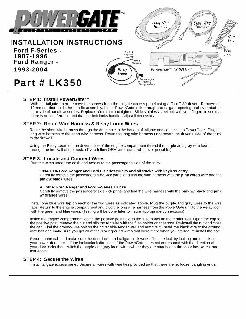
Ford F-Series - 1987-1996 Ford Ranger - 1993-2004
Part # LK350STEP 1: Install PowerGate™
With the tailgate open, remove the screws from the tailgate access panel using a Torx T-30 driver. Remove the 10mm nut that holds the handle assembly. Insert PowerGate lock through the tailgate opening and over stud on right side of handle assembly. Replace 10mm nut and tighten. Slide stainless steel bolt with your fi ngers to see that there is no interference and that the bolt locks handle. Adjust if necessary.
STEP 2: Route Wire Harness & Relay Loom WiresRoute the short wire harness through the drain hole in the bottom of tailgate and connect it to PowerGate. Plug the long wire harness to the short wire harness. Route the long wire harness underneath the driver’s side of the truck to the fi rewall.
Using the Relay Loom on the drivers side of the engine compartment thread the purple and gray wire loom through the fi re wall of the truck. (Try to follow OEM wire routes whenever possible.)
STEP 3: Locate and Connect WiresRun the wires under the dash and across to the passenger’s side of the truck.
1994-1996 Ford Ranger and Ford F-Series trucks and all trucks with keyless entryCarefully remove the passengers’ side kick panel and fi nd the wire harness with the pink w/red wire and the pink w/black wires
All other Ford Ranger and Ford F-Series TrucksCarefully remove the passengers’ side kick panel and fi nd the wire harness with the pink w/ black and pink w/ orange wires.
Install one blue wire tap on each of the two wires as indicated above. Plug the purple and gray wires to the wire taps. Return to the engine compartment and plug the long wire harness from the PowerGate unit to the Relay loom with the green and blue wires. (Testing will be done later to insure appropriate connections)
Inside the engine compartment locate the positive post next to the fuse panel on the fender well. Open the cap for the positive post, remove the nut and slip the red wire with the fuse holder on that post. Re-install the nut and close the cap. Find the ground-wire bolt on the driver side fender well and remove it. Install the black wire to the ground-wire bolt and make sure you get all of the black ground wires that were there when you started, re-install the bolt.
Return to the cab and make sure the door locks and tailgate lock work. Test the lock by locking and unlocking your power door locks. If the lock/unlock direction of the PowerGate does not correspond with the direction of your door locks then switch the purple and gray loom wires where they are attached to the door lock wires and test again.
STEP 4: Secure the WiresInstall tailgate access panel. Secure all wires with wire ties provided so that there are no loose, dangling ends.
Long Wire Harness
Short Wire Harness
Wire Ties
Wire Taps
PowerGateTM LK350 Unit
INSTALLATION INSTRUCTIONS
Relay Loom
Purple & Gray wires
Green & Blue wires
Red wire w/ fuse holder &
black ground-wire

Ford F-150/250 Light Duty & Super Crew - 1997 to 2010
Ford Super Duty - 1999 to 2005
Part # LK370
Long Wire Harness
Short Wire Harness
Wire Ties
Wire TapsINSTALLATION INSTRUCTIONS
STEP 1: Install PowerGate™Note: If your truck is equipped with an OEM manual door lock, install the PowerGate with the OEM manual lock in the unlocked position.
With tailgate open, remove the screws from the tailgate access panel using a Torx T-30 screwdriver. Remove the 10mm nut on the left side of the handle assembly. In order to get the powergate in the correct position you will need to temporarily remove the lock bar rod from the plastic rod retainer and move it aside. This will make it possible to maneuver the powergate assembly underneath the bar. Once the powergate is in place you can reconnect the lock bar rod into the rod retainer. Install PowerGate lock through the tailgate opening and over stud on left side of handle assembly. (see Fig. 1) Replace the 10mm nut and tighten. Slide the lock bolt with your fi ngers to insure that there is no interference and that the bolt works properly. Adjust if necessary.
STEP 2: Route the Wire Harness & Relay Loom WiresRoute the short wire harness through the drain hole in the bottom of tailgate and connect it to PowerGate. Plug the long wire harness to the short wire harness. Route the long wire harness underneath the driver’s side of the truck to the fi rewall.Using the Relay Loom on the drivers side of the engine compartment thread the purple and gray wire loom through the fi re wall of the truck. (Try to follow OEM wire routes whenever possible.)
STEP 3: Locate and Connect Wires
Plug the purple and gray wires to the wire taps. Return to the engine compartment and plug the long wire harness from the PowerGate unit to the Relay loom with the green and blue wires. (Testing will be done later to insure appropriate connections)
Inside the engine compartment locate the positive post next to the fuse panel on the fender well. Open the cap for the positive post, remove the nut and slip the red wire with the fuse holder on that post. Re-install the nut and close the cap. Find the ground-wire bolt on the driver side fender well and remove it. Install the black wire to the ground-wire bolt and make sure you get all of the black ground wires that were there when you started, re-install the bolt.
Return to the cab and make sure the door locks and tailgate lock work. Test the lock by locking and unlocking your power door locks. If the lock/unlock direction of the PowerGate does not correspond with the direction of your door locks then switch the purple and gray loom wires where they are attached to the door lock wires and test again.
STEP 4: Secure WiresInstall tailgate access panel. Secure all wires with wire ties provided so that there are no loose, dangling ends.
PowerGateTM LK370 Unit
Relay Loom
Purple & Gray wires
Green & Blue wires
Red wire w/ fuse holder &
black ground-wire
2008-2010 F150/F250 Light Duty & Supercrew
1997-2007 F150/250 Light Duty & Supercrew
2004- 2005 Super Duty 1999- 2003 Super Duty
Route the wires through the fi rewall on the drivers side. Locate the blue w/ green and gray w/ brown wires inside the drivers side kick panel. Install one blue wire tap on the blue w/ green stripe wire and one blue wire tap on the gray w/ brown stripe wire.
Run wires under the dash across to the passengers’ side of the truck carefully remove the passengers’ side kick-panel to fi nd the wire harness with the pink w/black wire and the red w/orange wire. Install one blue wire tap on the pink w/black and one blue wire tap on the red w/orange wire for these trucks.
Run wires under the dash across to the passengers’ side of the truck carefully remove the passengers’ side sill plate near the base of the seat belt to fi nd the wire harness with the red w/ orange stripe and pink w/ black stripe wires. Install one blue wire tap on the red w/ orange stripe wire and one blue wire tap on the pink w/ black stripe wire.
Route the wires through the fi rewall on the drivers side. Locate the red w/ orange stripe and pink w/ black stripe wires under the dash above the steering column. Install one blue wire tap on the red w/ orange stripe wire and one blue wire tap on the pink w/ black stripe wire.
Fig. 1
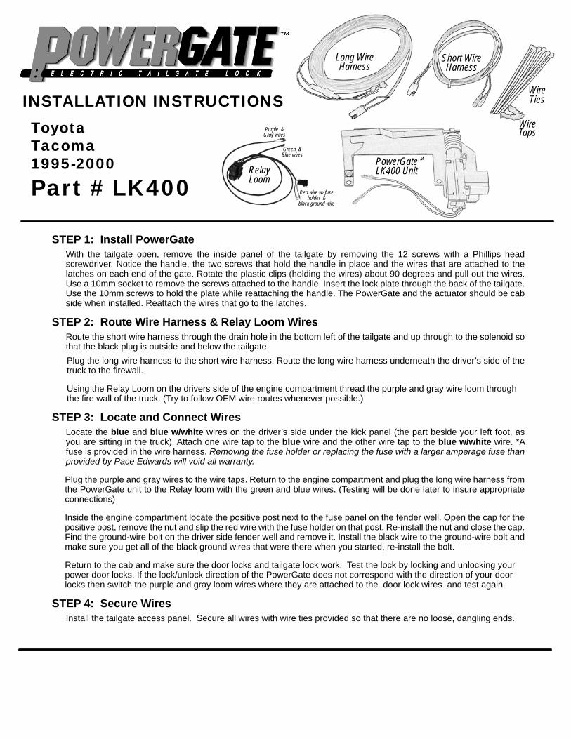
ToyotaTacoma1995-2000
Part # LK400
Long Wire Harness
Short Wire Harness
Wire Ties
Wire Taps
PowerGateTM LK400 Unit
INSTALLATION INSTRUCTIONS
STEP 1: Install PowerGateWith the tailgate open, remove the inside panel of the tailgate by removing the 12 screws with a Phillips head screwdriver. Notice the handle, the two screws that hold the handle in place and the wires that are attached to the latches on each end of the gate. Rotate the plastic clips (holding the wires) about 90 degrees and pull out the wires. Use a 10mm socket to remove the screws attached to the handle. Insert the lock plate through the back of the tailgate. Use the 10mm screws to hold the plate while reattaching the handle. The PowerGate and the actuator should be cab side when installed. Reattach the wires that go to the latches.
STEP 2: Route Wire Harness & Relay Loom WiresRoute the short wire harness through the drain hole in the bottom left of the tailgate and up through to the solenoid so that the black plug is outside and below the tailgate. Plug the long wire harness to the short wire harness. Route the long wire harness underneath the driver’s side of the truck to the fi rewall.
Using the Relay Loom on the drivers side of the engine compartment thread the purple and gray wire loom through the fi re wall of the truck. (Try to follow OEM wire routes whenever possible.)
STEP 3: Locate and Connect WiresLocate the blue and blue w/white wires on the driver’s side under the kick panel (the part beside your left foot, as you are sitting in the truck). Attach one wire tap to the blue wire and the other wire tap to the blue w/white wire. *A fuse is provided in the wire harness. Removing the fuse holder or replacing the fuse with a larger amperage fuse than provided by Pace Edwards will void all warranty.
Plug the purple and gray wires to the wire taps. Return to the engine compartment and plug the long wire harness from the PowerGate unit to the Relay loom with the green and blue wires. (Testing will be done later to insure appropriate connections)
Inside the engine compartment locate the positive post next to the fuse panel on the fender well. Open the cap for the positive post, remove the nut and slip the red wire with the fuse holder on that post. Re-install the nut and close the cap. Find the ground-wire bolt on the driver side fender well and remove it. Install the black wire to the ground-wire bolt and make sure you get all of the black ground wires that were there when you started, re-install the bolt.
Return to the cab and make sure the door locks and tailgate lock work. Test the lock by locking and unlocking your power door locks. If the lock/unlock direction of the PowerGate does not correspond with the direction of your door locks then switch the purple and gray loom wires where they are attached to the door lock wires and test again.
STEP 4: Secure WiresInstall the tailgate access panel. Secure all wires with wire ties provided so that there are no loose, dangling ends.
Relay Loom
Purple & Gray wires
Green & Blue wires
Red wire w/ fuse holder &
black ground-wire

Toggle switch
Part # LK902 PowerGateTM Toggle Switch
INSTALLATION INSTRUCTIONS
STEP 1: Mount SwitchFind a location on the dashboard for your PowerGate™ toggle switch, keeping in mind that the switch may be needed to be operated from outside the driver’s door. Make sure to check the reverse side of the dash to insure that the area is clear of all interference and drill a 15/32” or a .468” hole in the dash at the desired location. Remove the kurled nut and adjust the hex nut so that the threaded housing protrudes only two threads through the dashboard. Push the switch, handle fi rst, outwards through the hole and install the kurled nut over the threaded housing and tighten. The hex nut on the threaded housing allows you to adjust how far the toggle switch protrudes through the dashboard.
STEP 2: Wire SwitchUsing a 12-volt probe tester, locate a continuous line of power and connect the red wire from the PowerGate™ toggle switch to that line. Find a ground wire under the dash and connect the blue wire to this ground. Plug the two remaining female spade terminals to the white PowerGate™ lock wires.
STEP 3: Test SwitchNormal operation has the switch up to unlock and switch down to lock the PowerGate™. If pressing the switch down unlocks the PowerGate™, change the two spade terminal connections and test it again.