installation instructions/user guide model ur2-4 …
TRANSCRIPT

INSTALLATION INSTRUCTIONS/USER GUIDE
MODEL UR2-4
UNIVERSAL DOOR CONTROLLER
P:\INSTALLATION INST\Power Supplies\INST-UR\INST-UR2-4.vsd REV C 12-18 Page 1
801 Avenida Acaso, Camarillo, Ca. 93012 • (805) 494-0622 •
www.sdcsecurity.com • E-mail: [email protected]

P:\INSTALLATION INST\Power Supplies\INST-UR\INST-UR2-4.vsd REV C 12-18 Page 2
1 Introduction……………………………………………………………………………………………………………………………………………………………. 3
1.1 Using this Manual – READ THIS SECTION FIRST!…………………………………………………………………………………………. 3
1.2 Product Features…………………………………………………………………………………………………………………………………………. 3
2 Select Operating Mode……………………………………………………………………………………………………………………………………………. 4
3 Setup Module Operating Modes…………………………………………………………………………………………………………………………... 5
3.1 Interlock A ………………………………………………………………………………………………………………………………………………... 5
3.2 Mantrap B ………………………………………………………………………………………………………………………………………………... 7
3.3 Interlock C ……………………………………………………………………………………………………………………………………………….. 9
3.4 2-Door Communicating Bath System ……………………………………………………………………………………………………….. 11
3.5 Single Relay Control Mode Setup …………………………………………………………………………………………………………….. 13
3.6 Dual Relay Control Mode Setup ………………………………………………………………………………………………………………. 15
APPENDIX A ………………………………………………………………………………………………………………………………………………………………... 17
A-1 Technical Specifications …………………………………………………………………………………………………………………………... 17
A-2 Board Layout ……………………………………………………………………………………………………………………………………………. 17
Fig A-1 – UR2-4 PCBA Layout ……………………………………………………………………………………………………………………………... 17
A-3 Wiring Diagrams
Fig A-2 Interlock A Mode …………………………………………………………………………………………………………………………………….. 20
Fig A-3 Mantrap B Mode ……………………………………………………………………………………………………………………………………. 21
Fig A-4 Interlock C Mode …………………………………………………………………………………………………………………………………... 22
Fig A-5 2-Door Communicating Bath …………………………………………………………………………………………………………………. 23
Fig A-6 Single Relay Control Mode ……………………………………………………………………………………………………………………. 24
Fig A-7 Dual Relay Control Mode …………………………………………………………………………………………………………………….... 25
A-4 Troubleshooting ………………………………………………………………………………………………………………………………………………...26
Table of Contents

P:\INSTALLATION INST\Power Supplies\INST-UR\INST-UR2-4.vsd REV C 12-18 Page 3
1 Introduction
The UR2-4 Universal Door Control Module is a microprocessor based relay controller that provides multiple pre-programmed, field-selectable modes for controlling and interlocking two doors, using electric door locking devices.
The standard UR2-4 allows:Complex interlocking and control of up to 2 doors. Complex input/output linking for up to 4 sets of input and output points Control of doors using access control system, standalone readers, keypads, or pushbutton switches.Continued interlock operation, even if system or network fails (as long as power is backed up)
Typical Applications include:Mantraps (controlled entrances for schools, government buildings, bank ATM lobbies, and control rooms),Airlocks (prevent contamination of clean rooms, etc.),Sally Ports (for transferring detainees into jails, police stations, etc),High Security Areas (casino cash rooms, jewelry, gold or currency handling areas),
1.1 UsingthisManual– READTHISSECTIONFIRST!1. Select Operating Mode (Section 2, Page 4)
2. Setup Module for selected operating mode using DIP switches (Section 3, Step 1)
3. Connect all hardware and apply power (Section 3, Steps 2-6, and Appendix A)
4. Test (Section 3, Step 7)
5. Troubleshooting (Appendix A-4)
For example, if you selected Mantrap B Mode, you would use Section 3.2, Steps 1-7 to configure the unit, and would
refer to Appendix A, Figure A-3 for wiring information.
1.2 ProductFeatures
Product Features include:3 selectable Interlock (airlock, mantrap) modesCommunicating (shared) bathroom modeSingle or Dual input/output linking modes with outputs configurable as:
o Conventional Relay (CR) – Input Trackingo Latching Relay (LR) – Pulse on, pulse off – Toggle Modeo Time Delay Relay (TD) – 1-65 seconds - Timed Outputo Dual Function Relay (CR/LR, TD/LR, TD/CR, CR/CR)
Each output relay is field selectable as a dry contact or a “wet” voltage outputCentralized wiring for all locks, access controls, monitoring contacts, and peripheral equipmentOnboard input/output status lights for easy troubleshooting3 system control inputs: Lock All, Unlock All, System LockoutEmergency release input for fire panel interfaceRemovable terminal blocks simplify installation Customized solutions can be special-ordered (contact factory for information)Power with 12 or 24VDCProvides isolation and fuse protection for access control panels and door locking devicesCan be installed inside an SDC 600RFA Series Power Supply.
P:\INSTALLATION INST\Power Supplies\INST-UR\INST-UR2-4.vsd REV C 12-18 Page 4
2 SelectOperatingModeThe UR2-4’s pre-programmed operating modes are described in the paragraphs below. Modes 1, 2, & 3 are the most commonly used. Read the detailed method of operation and match the mode with your application. Setup and Test Procedures for each mode are included in Section 3, and Board Layout and Wiring Instructions are shown in Appendix A, Sections 1-3.
1- Interlock “A” 2-Door Setup - Both doors are normally closed and unlocked. This mode allows only one door to be open at any given time. Opening either door causes the other door to lock until the opened door returns to its normal state. Typical applications: normally unlocked entrances such as Airlocks or public entrances to secured areas (code or card not required). Setup instructions on Pages 5-6.
2- Mantrap “B” 2-Door Setup – Both doors are normally closed and locked. Use an Access Control System, Standalone reader, or remote release to unlock. This mode allows only one door to be opened at any given time. Unlocking any door causes the other door to be incapable of being unlocked until the unlocked door returns to its normal state. Typical applications: high-security entrances controlled by an access control system or standalone reader (requiring code or card), such as a Mantrap equipped with biometrics and/or metal detector. Setup instructions on Pages 7-8.
3- Interlock “C” 2-Door Setup – Both Doors are normally closed. One door is normally locked or the other is normally unlocked. This mode allows both unlocked and locked entrances to the secured area, but only allows one door to be opened at any given time. There are 2 possible configurations (see Setup Page 9). Typical applications: Secured area with both unlocked and locked entrances. Setup info on Page 9-10.
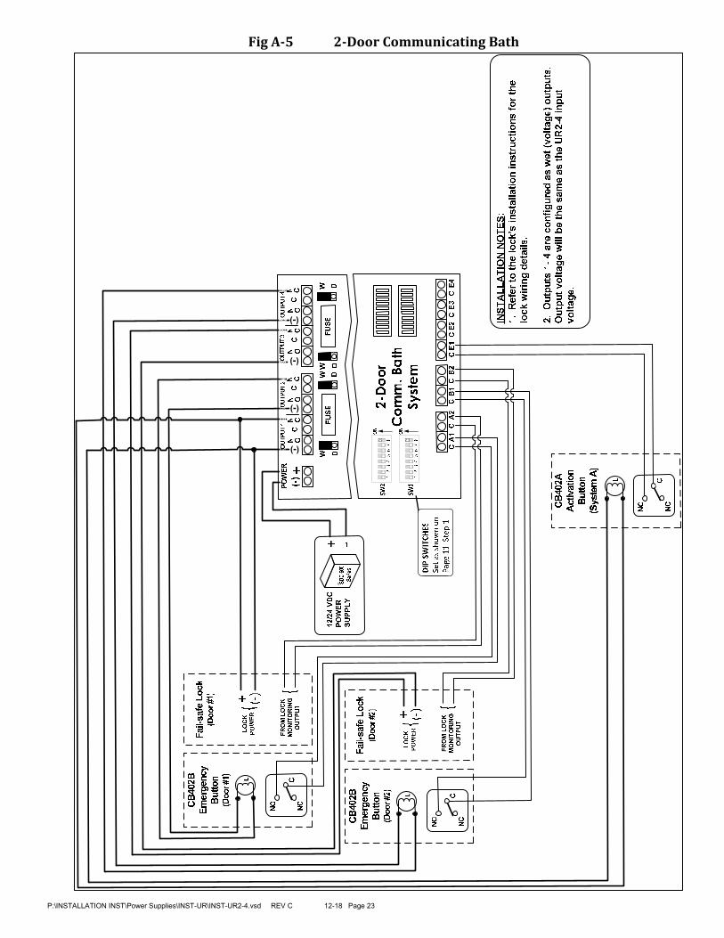
4- 2-Door Communicating (Shared) Bath System - Controls occupancy to a bathroom with two access doors. The user enters the bathroom, closes both doors and presses an Activation button locking both doors, lighting the indicators on the Activation and Emergency Unlock buttons, indicating that the bathroom is occupied. The locked condition can be cancelled using the Activation button or by retracting the latch on either door, depending on the locking hardware used. Typical application: shared bathrooms used to reduce construction and maintenance costs in hospitals and nursing homes. Setup info on Page 11-12.
5- Single Relay Control Mode - The UR2-4 provides four (4) independently controlled relay outputs.Inputs A1 & B1 each control (1) Fused, SPDT relay output, selectable as wet or dry Inputs A2 & B2 each control (1) Non-fused, SPDT relay output, selectable as wet or dry Each output relay is controlled by one dry contact input. (A1 controls Output 1, A2 controls Output 2, B1 controls Output 3, and B2 controls Output 4)Each output may be individually configured to operate as a conventional Tracking, Timed or Latching Relay.Typical Applications are for door locking devices and accessories, but the module can be used to control HVAC, lighting, or any device requiring complex input/output linking. Setup info on Page 13-14.
6- Dual Relay Control Mode - The UR2-4 operates as two (2) pairs of independently controlled output relays. (One pair for each controlled entrance.) Each output relay pair consists of
(1) Fused, SPDT lock output relay, selectable as wet or dry, (1) Non-fused, SPDT auxiliary (monitoring) output relay, selectable as wet or dry
Dual Relay Operation is as follows:Activating Input A1 OR A2 will trigger Outputs 1 AND 2, Activating Input B1 OR B2 will trigger Outputs 3 AND 4,
One pair of dry contact inputs corresponds to each output relay. Typically the first input will connect to the output of an access control system, and the second input will connect to a remote open switch or the output of an Exit PIR device.
Each output may be individually configured to operate as a Tracking, Timed or Latching Relay. Typical Applications are for controlling door locking devices and associated equipment. The module can also be used to control HVAC, lighting, or any device requiring relay control. Setup info on Page 15-16.

P:\INSTALLATION INST\Power Supplies\INST-UR\INST-UR2-4.vsd REV C 12-18 Page 5
3 SetupModuleOperatingModes
3.1 InterlockAInterlock “A” Standard Operation: Both doors are normally closed and unlocked. Opening either door causes the other door to lock until the opened door returns to its normal state.
Refer to the Board Layout on Pages 17-19, and the Interlock “A” Mode wiring diagram on Page 20.
Follow the installation steps below before applying power to the UR2-4.
NOTE: It is assumed that the UR2-4 and locking hardware share the same power supply. UR2-4 can easily be
installed inside an SDC 600RFA Series Power Supply Enclosure.
Step 1 – Set DIP Switches
The DIP switch settings below are an example of the typical Interlock A setup. Adjust DIP switches SW2-5 & SW2-7 as needed. All other DIP switches should remain as shown below.
Figure3.1InterlockADIPSwitchSettings(Typical)
SW2-1 = OFF
SW2-2 = OFF
SW2-3 = OFF
SW2-4 = OFF
SW2-5 = OFFSets the polarity of the Door Monitoring Inputs w hen the
door is in the CLOSED position. {OFF = N/O; ON = N/C}
SW2-6 = OFF
SW2-7 = OFF
Sets the operation of all the Monitoring Relay Outputs.
{OFF = Relay w ill follow the Door Monitoring Input;
ON = Relay w ill follow the Lock Output Relay}
SW2-8 = ON
SW1 -1 = OFF
SW1 -2 = OFF
SW1 -3 = OFF
SW1 -4 = OFF
SW1 -5 = OFF
SW1 -6 = OFF
SW1 -7 = OFF
SW1 -8 = OFF
Must be ON
Must be OFF
Must be OFF
Must be OFF
Must be OFF
Must be OFF
Figure3.2InterlockADIPSwitchTable
SW1
SW2ON
ON
1 2 3 4 5 6 7 8
1 2 3 4 5 6 7 8

P:\INSTALLATION INST\Power Supplies\INST-UR\INST-UR2-4.vsd REV C 12-18 Page 6
Step 2 – Configure the Relay Outputs to be Wet (Voltage) or Dry (No voltage).Use the small, black WET/DRY Selection Jumpers to configure each output. Install Jumper over top 2 pins = WET. Install Jumper over bottom 2 pins = DRY.
On the typical Interlock A wiring diagram, the Lock Relays (Outputs 1 & 3) are configured to be wet outputs. The Monitoring Relays (Outputs 2 & 4) are dry.NOTE: It is recommended that any unused relays be configured as dry outputs.
Step 3 – Terminate the Lock Power WiringFollow the typical Interlock A wiring diagram for fail-safe or fail-secure locks. Be careful to observe lock voltage polarity.*WARNING: The UR board Relay Outputs must be protected against inductive kickback generated when power is removed from an inductive load (e.g., electric strikes). Refer to the lock manufacturer's installation manual or contact the manufacturer for kickback protection recommendations. (NOTE: MOV’s are shown on wiring diagrams, and one is included for each of the fused outputs.)NOTE: All low voltage wiring shall be 18-gauge minimum. The minimum lock power wire gauge shall be determined by the SDC wire gauge chart. Signal wire shall be 22-guage minimum.
Step 4 - Terminate the Door Monitoring InputsConnect the Door Monitoring Switches to Input terminals A1 & B1. This is a required connection for both door stations.Door Monitoring inputs (typically Door Position Switches), should be dry, Normally Open or Normally Closed switches, depending on the configuration of DIP Switch 2-5 (Step 1).NOTE: DIP Switch 2-5 configures the normal state of the Door Monitoring input when the door is in a CLOSED position.
Step 5 - Terminate Auxiliary Inputs and Outputs (OPTIONAL)
Auxiliary Inputs (E1-E4) – These inputs must be wired as dry, Normally Open switches. The input will only be active when closed (shorted). Monitoring Relay Outputs (Outputs 2 & 4) – Each door station provides a non-fused, SPDT monitoring relay. This output may be used to signal a Security Panel or to activate a Remote Annunciator. The relay is configurable as a Wet or Dry output (Step 2). The relay activation will follow the Lock Relay or follow the Door Monitoring Input, depending on the configuration of DIP Switch 2-7 (Step 1).
Step 6 - Connect a 12 or 24VDC Power Source to the UR2-4 Controller.Before applying power, verify that all the connections are securely terminated by gently pulling on each wire. Connect the voltage wiring to the Controller Power Input. Be careful to observe polarity.Verify that all the doors are closed & apply power to the controller.
Step 7 - Startup and Operation Verification.Verify the polarity of the Door Monitoring Inputs by observing the Status Lights located on the lower right of the UR2-4 controller.
Status Lights A1 & B1 will be OFF if DIP Switch 2-5 = OFF, or will be ON if DIP Switch 2-5 = ON.Test the standard operation of the interlock by opening any door. All other doors will lock until the unlocked door returns to its normal state (closed).

3.2 MantrapBMantrap “B” Standard Operation: Both doors are normally closed and locked. Each door may be individually unlocked using the Access Control System or a remote release. Unlocking either door causes the other door to be incapable of being unlocked until the unlocked door returns to its normal state.
Refer to the Board Layout on Pages 17-19, and the Mantrap “B” Mode wiring diagram on Page 21.
Follow the installation steps below before applying power to the UR2-4.
NOTE: It is assumed that the UR2-4 and locking hardware share the same power supply. UR2-4 can easily be
installed inside an SDC 600RFA Series Power Supply Enclosure.
The door unlock time will be determined by the Access Control System and by DIP Switches 2-1 through 2-4
(Step 1).
Step 1 - Set DIP SwitchesThe DIP switch settings below are an example of the typical Mantrap B setup. Adjust DIP switches SW2-1 thru SW2-7 as needed. All other DIP switches should remain as shown below.
Figure3.3MantrapBDIPSwitchSettings(Typical)
Figure3.4MantrapBDIPSwitchTable
P:\INSTALLATION INST\Power Supplies\INST-UR\INST-UR2-4.vsd REV C 12-18 Page 7
SW1
SW2
ON
ON
1 2 3 4 5 6 7 8
1 2 3 4 5 6 7 8
SW2-1 = ON
SW2-2 = OFF
SW2-3 = OFF
SW2-4 = OFF
SW2-5 = OFF
Sets the polarity of the Door Monitoring Inputs w hen the
door is in the CLOSED and/or LOCKED position.
{OFF = N/O; ON = N/C}
SW2-6 = OFFSets the polarity of Access Control Inputs w hen the sw itch
is in a normal (resting) state. {OFF = N/O; ON = N/C}
SW2-7 = OFF
Sets the operation of all the Monitoring Relay Outputs.
{OFF = Relay w ill follow the Door Monitoring Input;
ON = Relay w ill follow the Lock Output Relay}
SW2-8 = ON
SW1 -1 = ON Must be ON
SW1 -2 = ON Must be ON
SW1 -3 = OFF
SW1 -4 = OFF
SW1 -5 = OFF
SW1 -6 = OFF
SW1 -7 = OFF
SW1 -8 = OFF
SW2-1 through 2-4 set the unlock time of the Lock Relay.
NOTE: This is in addition to your Access Control System
unlock time.
SW2-1 ON = 5 sec., OFF = 0 sec.;
SW2-2 ON = 1 0 sec., OFF = 0 sec.;
SW2-3 ON = 20 sec., OFF = 0 sec.;
SW2-4 ON = 30 sec., OFF = 0 sec.;
Sw itch times are additive. {All OFF = 1 sec.; All ON = 65

Step 2 - Configure the Relay Outputs to be Wet (Voltage) or Dry.Use the small, black WET/DRY Selection Jumpers to configure each output.Install Jumper over top 2 pins = WET. Install Jumper over bottom 2 pins = DRY
On the typical Mantrap B wiring diagram, the Lock Relays (Outputs 1 & 3) are configured to be wet outputs. The Monitoring Relays (Outputs 2 & 4) are dry.NOTE: It is recommended that any unused relays be configured as dry outputs.
Step 3 - Terminate the Lock Power WiringFollow the typical Mantrap B wiring diagram for fail-safe or fail-secure locks. Be careful to observe lock voltage polarity.WARNING: The UR board Relay Outputs must be protected against inductive kickback generated when power is removed from an inductive load (e.g., electric strikes). Refer to the lock manufacturer's installation manual or contact the manufacturer for kickback protection recommendations. (NOTE: MOV’s are shown on wiring diagrams, and one is included for each of the fused outputs.)NOTE: All low voltage wiring shall be 18-gauge minimum. The minimum lock power wire gauge shall be determined by the SDC wire gauge chart. Signal wire shall be 22-guage minimum.
Step 4 - Terminate the Access Control and Door Monitoring InputsConnect the Door Monitoring Switches to input terminals A1 & B1. This is a required connection.Connect Access Control or remote releases to input terminals A2 & B2. This is a required connection.Door Monitoring and Access Control inputs should be dry, Normally Open or Normally Closed switches, depending on the configuration of DIP Switches 2-5 and 2-6, respectively.NOTE: DIP Switch 2-5 configures the normal state of the Door Monitoring input when the door is in a CLOSED and/or LOCKED position.
Step 5 - Terminate Auxiliary Inputs and Outputs (OPTIONAL)Auxiliary Inputs (E1-E4) – These inputs must be wired as dry, Normally Open switches. The input will only be active when closed (shorted). Monitoring Relay Outputs (Outputs 2 & 4) – Each door station provides a non-fused, SPDT monitoring relay. This output may be used to signal a Security Panel or to activate a Remote Annunciator. The relay is configurable as a Wet or Dry output (Step 2). The relay activation will follow the Lock Relay or follow the Door Monitoring Input, depending on the configuration of DIP Switch 2-7 (Step 1).
Step 6 - Connect a 12 or 24VDC Power Source to the UR2-4 Controller.Before applying power, verify that all the connections are securely terminated by gently pulling on each wire. Terminate the voltage wiring to the Controller Power Input. Be careful to observe polarity.Verify that all the doors are closed & apply power to the controller.
Step 7. UR2-4 Controller Startup and Operation Verification.Verify the polarity of the Access Control & Door Monitoring Inputs by observing the Status Lights located on the lower right of the UR2-4 controller.Status Lights A1 & B1 will be OFF if DIP Switch 2-5 = OFF, or will be ON if DIP Switch 2-5 = ON.Status Lights A2 & B2 will be OFF if DIP Switch 2-6 = OFF, or will be ON if DIP Switch 2-6 = ON.Test the standard operation of the mantrap by unlocking any door using the Access Control System or remote release. All other doors will be incapable of being unlocked until the unlocked door returns to its normal state (closed & locked).
P:\INSTALLATION INST\Power Supplies\INST-UR\INST-UR2-4.vsd REV C 12-18 Page 8

3.3 InterlockCInterlock “C” Standard Operation: Both doors are normally closed. Either door may be locked and the second door is normally unlocked.There are 2 possible configurations:
2 Doors: Door 1 – Locked, Door 2 – UnlockedDoor 1 – Unlocked, Door 2 – Locked
The normally locked doors may be unlocked using the Access Control System. Unlocking or opening the normally locked door will lock the normally unlocked door. Opening the normally unlocked door will make the locked door incapable of being unlocked, until the unlocked/opened door returns to its normal state.
Refer to the Board Layout on Pages 17-19, and the Interlock “C” Mode wiring diagram on Page 22.Follow the installation steps below before applying power to the UR2-4. NOTE: It is assumed that the UR2-4 and locking hardware share the same power supply. UR2-4 can easily be installed inside an SDC 600RFA Series Power Supply Enclosure.
Step 1 – Set DIP SwitchesThe DIP switch settings below are an example of a typical Interlock “C” setup.
Use DIP switches SW1-1 and SW1-2 to select the Interlock “C” modeAdjust DIP switches SW2-1 thru SW2-7 as needed. All other DIP switches should remain as shown below.
Figure3.5InterlockCDIPSwitchSettings(Typical)
Fig3.6InterlockCDIPSwitchTable
Fig3.7InterlockCDoorConfigurations
P:\INSTALLATION INST\Power Supplies\INST-UR\INST-UR2-4.vsd REV C 12-18 Page 9
SW2-1 = ON
SW2-2 = OFF
SW2-3 = OFF
SW2-4 = OFF
SW2-5 = OFFSets the polarity of the Door Monitoring Inputs w hen the door is
in the CLOSED position. {OFF = N/O; ON = N/C}
SW2-6 = OFFSets the polarity of Access Control Inputs w hen the sw itch is
in a normal (resting) state. {OFF = N/O; ON = N/C}
SW2-7 = ON
Sets the operation of all the Monitoring Relay Outputs.
{OFF = Relay w ill follow the Door Monitoring Input;
ON = Relay w ill follow the Lock Output Relay}
SW2-8 = ON
SW1 -1 = ON {OFF = Door 1 - Unlocked; ON = Door 1 - Locked}
SW1 -2 = OFF {OFF = Door 2 - Unlocked; ON = Door 2 - Locked}
SW1 -3 = OFF
SW1 -4 = OFF
SW1 -5 = OFF
SW1-6 = OFF
SW1-7 = OFF
SW1-8 = OFF
SW2-1 through 2-4 set the unlock time of the Lock Relay for
the Door 1.
NOTE: This is in addition to your Access Control System
unlock time.
SW2-1 ON = 5 sec., OFF = 0 sec.;
SW2-2 ON = 1 0 sec., OFF = 0 sec.;
SW2-3 ON = 20 sec., OFF = 0 sec.;
SW2-4 ON = 30 sec., OFF = 0 sec.;
Sw itch times are additive. {All OFF = 1 sec.; All ON = 65 sec.}
SW SW
1-1 1-2
Door1 - Locked; Door 2 - Unlocked ON OFF
Door1 - Unlocked; Door 2 - Locked OFF ON
Interlock "C" Configurations
2-Door
SW1
SW2ON
ON
1 2 3 4 5 6 7 8
1 2 3 4 5 6 7 8

Step 2 – Configure the Relay Outputs to be Wet (Voltage) or Dry.Use the red WET/DRY Selection Jumpers to configure each output. Install Jumper over top 2 pins = WET. Install Jumper over bottom 2 pins = DRY
On the typical Interlock C wiring diagram, the Lock Relays (Outputs 1 & 3) are configured to be wet outputs. The Monitoring Relays (Outputs 2 & 4) are dry.
Step 3 - Terminate the Lock Power WiringFollow the typical Interlock C wiring diagram for fail-safe or fail-secure locks. Be careful to observe lock voltage polarity.WARNING: The UR board Relay Outputs must be protected against inductive kickback generated when power is removed from an inductive load (e.g., electric strikes). Refer to the lock manufacturer's installation manual or contact the manufacturer for kickback protection recommendations. (NOTE: MOV’s are shown on wiring diagrams, and one is included for each of the fused outputs.)NOTE: All low voltage wiring shall be 18-gauge minimum. The minimum lock power wire gauge shall be determined by the SDC wire gauge chart. Signal wire shall be 22-guage minimum.
Step 4 - Terminate the Access Control and Door Monitoring InputsNOTE: The Interlock “C” wiring diagram is shown configured with Door 1 normally locked, and Door 2 normally unlocked door).Connect the Door Monitoring Switches to input terminals A1 & B1. This is a required connection.Connect Access Control or remote releases to input terminals A2 & B2. This connection is ONLY required for normally locked doors. Door Monitoring and Access Control inputs should be dry, Normally Open or Normally Closed switches, depending on the configuration of DIP Switches 2-5 and 2-6, respectively.NOTE: DIP Switch 2-5 configures the normal state of the Door Monitoring input when the door is in a CLOSED and/or LOCKED position.
Step 5 - Terminate Auxiliary Inputs and Outputs (OPTIONAL)Auxiliary Inputs (E1-E4) – These inputs must be wired as dry, Normally Open switches. The input will only be active when closed (shorted). Monitoring Relay Outputs (Outputs 2 & 4) – Each door station provides a non-fused, SPDT monitoring relay. This output may be used to signal a Security Panel or to activate a Remote Annunciator. The relay is configurable as a Wet or Dry output (Step 2). The relay activation will follow the Lock Relay or follow the Door Monitoring Input, depending on the configuration of DIP Switch 2-7 (Step 1).
Step 6 - Connect a 12 or 24VDC Power Source to the UR2-4 Controller.Before applying power, verify that all the connections are securely terminated by gently pulling on each wire. Terminate the voltage wiring to the Controller Power Input. Be careful to observe polarity.Verify that all the doors are closed & apply power to the controller.
Step 7 - UR2-4 Controller Startup and Operation Verification.Verify the polarity of the Access Control & Door Monitoring Inputs by observing the Status Lights located on the lower right of the UR2-4 controller.Status Lights A1 & B1 will be OFF if DIP Switch 2-5 = OFF, or will be ON if DIP Switch 2-5 = ON.Status Lights A2 & B2 will be OFF if DIP Switch 2-6 = OFF, or will be ON if DIP Switch 2-6 = ON.Test the standard operation of the interlock by unlocking any door or by opening the unlocked door(s). All other doors will be incapable of being opened/unlocked until the opened door returns to its normal state.
P:\INSTALLATION INST\Power Supplies\INST-UR\INST-UR2-4.vsd REV C 12-18 Page 10

P:\INSTALLATION INST\Power Supplies\INST-UR\INST-UR2-4.vsd REV C 12-18 Page 11
3.4 2-DoorCommunicatingBathSystemStandard Operation:
Controls occupancy to a bathroom with two access doors. The user enters the bathroom, closes both doors and presses an Activation button locking both doors, lighting the indicators on the Activation and Emergency Unlock buttons, indicating the bathroom is occupied. The locked condition can be cancelled using the Activation button or by retracting the latch on either door, depending on the locking hardware used. System Deactivation: When using EMLocks®, pressing the Activation button a second time or when using fail-safe electric strikes or electrified locksets, operating the inside lever to retract the latch on either door will unlock both doors and turn off all indicator lamps. Using a key override from the outside to enter either door will also reset the system and unlock both doors. Emergency Override: Emergency Unlock buttons located outside each bathroom door will immediately unlock its specified door and indicate its activation by causing the button’s indicator lamp to flash. Pressing the Emergency Unlock button a second time will return the door to the locked state and the indicator lamp will return to a steady lighted state. Pressing the Activation button during an emergency override, will reset the system and unlock both doorsRefer to the Board Layout on Pages 17-19, and the 2-Door Communicating Bath System wiring diagram on Page 23.Follow the installation steps below before applying power to the UR2-4. It is assumed that the UR2-4 and locks will share the same power supply. UR2-4 can easily be installed inside an SDC 600RFA Series Power Supply Enclosure.
Step 1 – Set DIP SwitchesThe DIP switch settings for a 2-Door Communicating Bath System must be set as shown below. Adjust SW1-7 as required.
Figure3.82-doorBathSystemDIPSwitchSettings
Figure3.92-doorBathDIPSwitchTable
SW1 -1 = OFF
SW1 -2 = OFF
SW1 -3 = OFF
SW1 -4 = OFF
SW1 -5 = OFF
SW1 -6 = OFF
SW1 -7 = OFF
SW1 -8 = ON
SW2-1 = OFF
SW2-2 = OFF
SW2-3 = OFF
SW2-4 = OFF
SW2-5 = OFF
SW2-6 = OFF
SW2-7 = OFF
SW2-8 = ON
SW1
SW2ON
ON
1 2 3 4 5 6 7 8
1 2 3 4 5 6 7 8

P:\INSTALLATION INST\Power Supplies\INST-UR\INST-UR2-4.vsd REV C 12-18 Page 12
Step 2 – Configure the Relay Outputs to be Wet (Voltage) or Dry.Use the red WET/DRY Selection Jumpers to configure each output.Install Jumper over top 2 pins = WET.
All Outputs (1-4) are configured to be wet outputs.The relay output voltage will be the same as the UR2-4 input voltage (12 or 24 VDC).
Step 3 - Terminate the Activation and Emergency Unlock ButtonsConnect the (2) Emergency Unlock buttons and (1) Activation button as shown on the Communicating Bath system wiring diagram.All button switches are wired Normally Open. Button lamp voltage is not polarity sensitive.
Step 4 - Terminate the Lock Power and Lock Monitoring Options Select your specific lock type from one of the three choices below. Follow the typical Communicating Bath system wiring diagram. Be careful to observe lock voltage polarity.WARNING: The UR board Relay Outputs must be protected against inductive kickback generated when power is removed from an inductive load (e.g., electric strikes). Refer to the lock manufacturer's installation manual or contact the manufacturer for kickback protection recommendations. (NOTE: MOV’s are shown on wiring diagrams, and one is included for each of the fused outputs.)NOTE: All lock monitoring options below (LBM, DPS, and/or REX) shown wired so that the circuit is OPEN when the doors are CLOSED and LATCHED.
34
56
78
Fig3.10– Comm.BathLockWiringUsingEMLocks®
Fig3.11- Comm.BathLockWiringUsing
Fail-safeUni-FLEX™ElectricStrikesFig3.12– Comm.BathLockWiringUsing
Fail-safeSelectric®ProLocks
Step 5 - Connect a 12 or 24VDC Power Source to the UR2-4 Controller.Before applying power, verify that all the connections are securely terminated by gently pulling on each wire. Terminate the voltage wiring to the Controller Power Input. Be careful to observe polarity.Verify that both doors are closed & apply power to the controller.
Step 6- UR2-4 Controller Startup and Operation Verification.Verify the polarity of the inputs by observing the Status Lights located on the lower right of the controller.With the system at rest, Status Lights A1, A2, B1, B2, & E1 should all be turned off.Test the standard operation of the Communicating Bath System as described on Page 11.

P:\INSTALLATION INST\Power Supplies\INST-UR\INST-UR2-4.vsd REV C 12-18 Page 13
3.5 SingleRelayControlModeSetup
Standard Operation: In Single Relay Control Mode, the UR2-4 provides four (4) independently controlled relay outputs.
Outputs 1 & 3 each provide:A fused, SPDT lock output, selectable as wet (voltage) or dry
Outputs 2 & 4 each provide:A non-fused, SPDT lock output, wet (voltage) or dry
Each output is controlled by one dry contact input. (A1 controls Output 1, A2 controls Output 2, B1 controls Output 3, and B2 controls Output 4)Each output may be individually configured to operate as a Conventional Tracking (CR), Timed (TD) or Latching (LR) RelayRefer to the Board Layout on Pages 17-19, and the Single Relay Control Mode wiring diagram on Page 24.Follow the installation steps below before applying power to the UR2-4. NOTE: It is assumed that the UR2-4 and locks will share the same power supply. UR2-4 can easily be installed inside an SDC 600RFA Series Power Supply Enclosure.
Step 1 – Set DIP SwitchesThe DIP switch settings below are an example of the typical Single Relay Control Mode Setup as shown on Page 24. A) Use DIP switches SW1-1 through SW1-4 to select the operation of each trigger input: CR, TD, or LR.If DIP switch SW2-6 = OFF, each input is selectable as a CR or TD only. If DIP switch SW2-6 = ON, each input is selectable as a LR or TD only.B) Adjust DIP switches SW2-1 thru SW2-6 as required. All other DIP switches should remain as shown below.
Figure3.13- SingleRelayControlDIPSwitchSettings
(ShownwithallrelaysinCRMode)
Figure3.14- SingleRelayControlDIPSwitchTable
SW2-1 = ON
SW2-2 = OFF
SW2-3 = OFF
SW2-4 = OFF
SW2-5 = OFFSets the polarity of ALL the trigger inputs w hen the trigger
is in a non-activated state. {OFF = N/O; ON = N/C}
SW2-6 = OFF{OFF = Each Station is selectable as CR or TD only;
ON = Each Station input is selectable as LR or TD only}
SW2-7 = OFF
SW2-8 = OFF
SW1 -1 = ON Station A1 Mode Selection {OFF = CR or LR; ON = TD}
SW1 -2 = ON Station A2 Mode Selection {OFF = CR or LR; ON = TD}
SW1 -3 = OFF Station B1 Mode Selection {OFF = CR or LR; ON = TD}
SW1 -4 = OFF Station B2 Mode Selection {OFF = CR or LR; ON = TD}
SW1 -5 = OFF
SW1 -6 = OFF
SW1 -7 = OFF
SW1 -8 = OFF
When using TD mode, SW 2-1 through 2-4 set the unlock
delay time of the Lock Relay.
SW2-1 ON = 5 sec., OFF = 0 sec.;
SW2-2 ON = 1 0 sec., OFF = 0 sec.;
SW2-3 ON = 20 sec., OFF = 0 sec.;
SW2-4 ON = 30 sec., OFF = 0 sec.;
Sw itch times are additive. {All OFF = 1 sec.; All ON = 65
sec.}

P:\INSTALLATION INST\Power Supplies\INST-UR\INST-UR2-4.vsd REV C 12-18 Page 14
Step 2 – Configure the Relay Outputs to be Wet (Voltage) or Dry.Use the red WET/DRY Selection Jumpers to configure each output. Install Jumper over top 2 pins = WET. Install Jumper over bottom 2 pins = DRYOn the typical Single Relay Control Mode wiring diagram, all relay outputs are configured as wet outputs.The relay output voltage will be the same as the UR2-4 input voltage (12 or 24 VDC).NOTE: It is recommended that any unused relays be configured as dry outputs.
Step 3 - Terminate the Output WiringIf applicable, follow the Single Relay Control Mode wiring diagram for fail-safe or fail-secure locks. Be careful toobserve lock voltage polarity. Alternatively, outputs may be configured as dry, Form C outputs.*WARNING!: The UR board Relay Outputs must be protected against inductive kickback generated when power is removed from an inductive load (e.g., electric strikes). Refer to the lock manufacturer's installation manual or contact the manufacturer for kickback protection recommendations. (NOTE: MOV’s are shown on wiring diagrams, and one is included for each of the fused outputs.)NOTE: All low voltage wiring shall be 18-gauge minimum. The minimum lock power wire gauge shall be determined by the SDC wire gauge chart. Signal wire shall be 22-guage minimum.
Step 4 - Terminate the Station Trigger InputsConnect each station’s trigger input as required. Trigger inputs are A1, A2, B1, & B2.All the trigger inputs should be dry, momentary, Normally Open or Normally Closed switches, depending on the configuration of DIP Switch 2-5 (Step 1).NOTE: DIP Switch 2-5 configures the normal (resting) state of the trigger input. If Normally Closed inputs are used, any unused trigger inputs from those listed above will need to be shorted.
Step 5 - Terminate Auxiliary Inputs (OPTIONAL)Auxiliary Inputs (E1-E4) – These inputs must be wired as dry, Normally Open switches. The input will only be active when closed (shorted).
Step 6 - Connect a 12 or 24VDC Power Source to the UR2-4 Controller.Before applying power, verify that all the connections are securely terminated by gently pulling on each wire. Terminate the voltage wiring to the Controller Power Input. Be careful to observe polarity.Verify that all the trigger inputs are in their normal (resting) state & apply power to the controller.
Step 7 - UR2-4 Controller Startup and Operation Verification.Verify the polarity of each Station trigger input by observing the Status Lights located on the lower right of thecontroller.Status Lights A1, A2, B1, & B2 will be OFF if DIP Switch 2-5 = OFF, or will be ON if DIP Switch 2-5 = ON.Test the standard operation of each station control relay by momentarily pressing the trigger input. In CR mode, the respective door will unlock while the trigger input is activated, and relock when the trigger is released.In TD mode, the respective door will unlock when the trigger input is activated. Releasing the trigger input will start the unlock timer and the door will remain unlocked. The door will relock after the set unlock time has expired. In LR mode, the respective door will unlock when the trigger input is momentarily activated and released. The door will remained unlocked indefinitely until the trigger input is reactivated.

3.6 DualRelayControlModeSetup
Standard Operation: In Dual Relay Control Mode, the UR2-4 operates as two (2) pairs of independently controlled relay stations. Each output station pair consists of:
A fused, SPDT lock output, selectable as wet(voltage) or dry, A non-fused, SPDT auxiliary (monitoring) output, selectable as wet(voltage) or dry,
Dual Relay Operation is as follows:Activating Input A1 OR A2 will trigger Outputs 1 AND 2, Activating Input B1 OR B2 will trigger Outputs 3 AND 4,
One pair of dry contact inputs corresponds to each output relay. Typically the first input will connect to the output of an access control system, and the second input will connect to a remote open switch or the output of an Exit PIR device.
Each output may be individually configured to operate as a Conventional Tracking (CR), Timed (TD) or Latching (LR) Relay.Refer to the Board Layout on Pages 17-19, and the DUAL RELAY CONTROL MODE wiring diagram on Page 25.Follow the installation steps below before applying power to the UR2-4. NOTE: It is assumed that the UR2-4 and locks will share the same power supply. UR2-4 can easily be installed inside an SDC 600RFA Series Power Supply Enclosure.
Step 1 – Set DIP Switches
The DIP switch settings below are an example of the typical Dual Relay Control Mode Setup as shown on Page 25.A) Use DIP switches SW1-1 through SW1-4 to select the operation of each trigger input: CR, TD, or LR.B) Adjust DIP switches SW2-1 thru SW2-5 as needed. All other DIP switches shall remain as shown below.
P:\INSTALLATION INST\Power Supplies\INST-UR\INST-UR2-4.vsd REV C 12-18 Page 15
Fig.3.15- DualRelayControlDIPSwitchSettings
(ShowninCRMode)
Figure3.16- DualRelayControlDIPSwitchTable
SW2-1 = ON
SW2-2 = OFF
SW2-3 = OFF
SW2-4 = OFF
SW2-5 = OFFSets the polarity of ALL the trigger inputs w hen the trigger is
in a non-activated state. {OFF = N/O; ON = N/C}
SW2-6 = OFF
SW2-7 = ON Must be ON
SW2-8 = OFF
SW1 -1 = OFF Output 1 Mode Selection {OFF = CR; ON = TD}
SW1 -2 = OFF Output 2 Mode Selection {OFF = CR; ON = LR}
SW1 -3 = OFF Output 3 Mode Selection {OFF = CR; ON = TD}
SW1 -4 = OFF Output 4 Mode Selection {OFF = CR; ON = LR}
SW1 -5 = OFF
SW1 -6 = OFF
SW1 -7 = OFF
SW1 -8 = OFF
When using TD mode, SW 2-1 through 2-4 sets the unlock
delay time of the relays.
SW2-1 ON = 5 sec., OFF = 0 sec.;
SW2-2 ON = 1 0 sec., OFF = 0 sec.;
SW2-3 ON = 20 sec., OFF = 0 sec.;
SW2-4 ON = 30 sec., OFF = 0 sec.;
Sw itch times are additive. {All OFF = 1 sec.; All ON = 65
sec.}

P:\INSTALLATION INST\Power Supplies\INST-UR\INST-UR2-4.vsd REV C 12-18 Page 16
Step 2 – Configure the Relay Outputs to be Wet (Voltage) or Dry.Use the red WET/DRY Selection Jumpers to configure each output. Install Jumper over top 2 pins = WET. Install Jumper over bottom 2 pins = DRYOn the typical Dual Relay Control Mode wiring diagram, the Lock Relays (Outputs 1& 3) are configured to bewet outputs. The Monitoring Relays (Outputs 2 & 4) are dry.The relay output voltage will be the same as the UR2-4 input voltage (12 or 24 VDC).NOTE: It is recommended that any unused relays be configured as dry outputs.
Step 3 - Terminate the Output WiringIf applicable, follow the typical Dual Relay Control Mode wiring diagram for fail-safe or fail-secure locks. Becareful to observe lock voltage polarity. Alternatively, outputs may be configured as dry, Form C outputs.*WARNING!: The UR board Relay Outputs must be protected against inductive kickback generated when power is removed from an inductive load (e.g., electric strikes). Refer to the lock manufacturer's installation manual or contact the manufacturer for kickback protection recommendations. (NOTE: MOV’s are shown on wiring diagrams, and one is included for each of the fused outputs.)NOTE: All low voltage wiring shall be 18-gauge minimum. The minimum lock power wire gauge shall be determined by the SDC wire gauge chart. Signal wire shall be 22-guage minimum.
Step 4 - Terminate the Station Trigger InputsConnect each station’s trigger input 1 and input 2, as required. Trigger inputs are A1, A2, B1, & B2.All the trigger inputs should be dry, momentary, Normally Open or Normally Closed switches, depending on the configuration of DIP Switch 2-5 (Step 1).NOTE: DIP Switch 2-5 configures the normal (resting) state of the trigger input. If Normally Closed inputs are used, any unused trigger inputs from those listed above will need to be shorted.
Step 5 - Terminate Auxiliary Inputs and Outputs (OPTIONAL)Auxiliary Inputs (E1-E4) – These inputs must be wired as dry, Normally Open switches. The input will only be active when closed (shorted). Monitoring Relay Outputs (Outputs 2 & 4) – Each door station provides a non-fused, SPDT monitoring relay. This output may be used to signal a Security Panel or to activate a Remote Annunciator. The relay is configurable as a Wet or Dry output (Step 2). The relay activation will follow the Lock Relay.
Step 6 - Connect a 12 or 24VDC Power Source to the UR2-4 Controller.Before applying power, verify that all the connections are securely terminated by gently pulling on each wire. Terminate the voltage wiring to the Controller Power Input. Be careful to observe polarity.Verify that all the trigger inputs are in their normal (resting) state & apply power to the controller.
Step 7 - UR2-4 Controller Startup and Operation Verification.Verify the polarity of each Station trigger input by observing the Status Lights located on the lower right of the controller.Status Lights A1, A2, B1, & B2 will be OFF if DIP Switch 2-5 = OFF,or will be ON if DIP Switch 2-5 = ON.Test the standard operation of each station control relay by momentarily pressing the trigger input. In CR mode, the respective door will unlock while the trigger input is activated, and relock when the trigger is released.In TD mode, the respective door will unlock when the trigger input is activated. Releasing the trigger input will start the unlock timer and the door will remain unlocked. The door will relock after the set unlock time has expired. In LR mode, the respective door will unlock when the trigger input is momentarily activated and released. The door will remained unlocked indefinitely until the trigger input is reactivated.

APPENDIXA
This section includes:Technical Specifications Board LayoutWiring for the Pre-Programmed ApplicationsTroubleshooting
A-1 TechnicalSpecifications
Input Voltage: 12 or 24VDC +/- 10%Input Current: 140 mA max. @ 12/24 VDCRelay Activation Inputs: 4 Dry, Optically Isolated
All Normally Open or Normally Closed (field selectable)Auxiliary Inputs: 4 Dry, Optically IsolatedRelay Outputs: 2 fused SPDT relays, 7A @ 30VDC
2 non-fused SPDT relays, 7A @ 30VDCIndividually configurable as a dry contact or voltage output (field selectable; voltage output same as input voltage)
Dimensions: 4.50" W x 5.00" H x 2" D
(114.3 x 127 x 50.8 mm)
A-2 BoardLayout
The UR2-4 microprocessor controlled relay board consists of 8 inputs and 4 Form C, SPDT relay outputs.
P:\INSTALLATION INST\Power Supplies\INST-UR\INST-UR2-4.vsd REV C 12-18 Page 17
4
2
3
6
5
7
1
1
2
3
4
8
5
6
7
8
Relay Outputs (4 total)
Output WET/DRY Selection Jumper (4 total)
Activation/Trigger Inputs (4 total)
Auxiliary Inputs (4 total)
Input Power Connection
Mode Configuration Dip Switches (2 banks – 8 position)
Input/Output Status LED’s
Fuses (2 total)

RELAY OUTPUTS – The UR2-4 provides four (4) individual SPDT relay outputs.
Outputs 1 & 3 are fused. These outputs are typically used to power the door locking hardware.
Outputs 2 & 4 are non-fused. These outputs are typically used as auxiliary (monitoring) relays. They may be used to power a remote status annunciator, or send a signal to a security panel.
WET/DRY SELECTION JUMPER – Each relay output may be configured as a wet (voltage) or dry output. Dry output is the default setting. Use the supplied jumpers to configure each relay individually.
Jumper over top 2 pins = WET Output Jumper over bottom 2 pins = DRY Output
When configured as a WET relay output:
The relay output voltage will be the same as the UR2-4 input voltage (12 or 24 VDC).
All (-) terminals are connected to ground.
(+DC) voltage will be on the “NC” terminal when the relay is inactive, and on the “NO” terminal when the relay is
active. The “C” terminal is not used when configured as a wet relay.
MAIN ACTIVATION INPUTS – The UR2-4 provides four (4) individual, optically isolated inputs. They are A1, A2, B1, & B2.
The inputs must be connected to a dry switch.
These inputs may be collectively configured as Normally Open or Normally Closed inputs.
NOTE: If Normally Closed inputs are selected, all unused inputs will need to be shorted.
P:\INSTALLATION INST\Power Supplies\INST-UR\INST-UR2-4.vsd REV C 12-18 Page 18
1
FAIL-
SECURE
LOCK
FAIL-SAFE
LOCK- +
- +
Monitoring
Relay
Output
2
3
} }
Input
A1
Input
A2
} }
Input
B1Input
B2
Station A Station B
Com
N/C
N/O
Dry
Switch

P:\INSTALLATION INST\Power Supplies\INST-UR\INST-UR2-4.vsd REV C 12-18 Page 19
AUXILIARY INPUTS – The UR2-4 provides four (4) individual dry, optically isolated auxiliary inputs.
NOTE: These input connections are optional and must be wired as Normally Open connections. The input will only be active when closed (shorted).
Input E1 – LOCK ALL – When activated, this input will lock all the doors, until the input is deactivated. Door
Monitoring Inputs will be ignored.
Input E2 – UNLOCK ALL – When activated, this input will unlock all the doors, until the input is deactivated. Door
Monitoring Inputs will be ignored.
Input E3– LOCKOUT – When activated, this input will cause all the lock outputs to remain in their current state,
and ignore changes to the Door Monitoring Inputs. Lock/Unlock All inputs will also be ignored.
Input E4 – EMERGENCY RELEASE (FIRE ALARM) – When activated, this input will simultaneously release all fail-
safe locks. Door Monitoring Inputs, Lock/Unlock All inputs, and the Lockout input will be ignored.
INPUT POWER CONNECTION – The UR2-4 must be powered by a filtered and regulated 12 or 24VDC Power Supply. SDC 600RFA Series Power Supplies are designed to accommodate and interface with up to two (2) UR2-4 controllers.
MODE CONFIGURATION DIP SWITCHES – The UR2-4 utilizes two (2) 8-position DIP switch modules for configuring the system operational modes. They are SW1 and SW2. (OFF position is towards the number)
STATUS LIGHTS – The UR2-4 provides diagnostic lights to show the status of each individual input and output on the board. Inputs are labeled A1, A2, B1, B2, E1, E2, E3, & E4. Outputs are labeled O1 thru O4.
If an input is closed (shorted),its corresponding light will be ON.
If an output is active (energized), its corresponding light will be ON.
FUSES – Outputs 1 & 3 are individually fused. Replace with Littelfuse p/n 0235002.HXP or equivalent
4
} }
Input
E1
Input
E2
} }
Input
E3
Input
E4
5
6
7
ON
ON
8

P:\INSTALLATION INST\Power Supplies\INST-UR\INST-UR2-4.vsd REV C 12-18 Page 20
A-3 WiringDiagrams FigA-2InterlockAMode
+
(-)
(-)
(-)
(-)

P:\INSTALLATION INST\Power Supplies\INST-UR\INST-UR2-4.vsd REV C 12-18 Page 21
FigA-3MantrapBMode
(-)
(-)
(-)
(-)

P:\INSTALLATION INST\Power Supplies\INST-UR\INST-UR2-4.vsd REV C 12-18 Page 22
FigA-4InterlockCMode
(-)
(-)
(-)
(-)
DIP
SW
ITC
HE
S
Se
t a
s sh
ow
n o
n
Pa
ge
9,
Ste
p 1
P:\INSTALLATION INST\Power Supplies\INST-UR\INST-UR2-4.vsd REV C 12-18 Page 23
FigA-5 2-DoorCommunicatingBath
(-)
(-)
(-)
(-)

P:\INSTALLATION INST\Power Supplies\INST-UR\INST-UR2-4.vsd REV C 12-18 Page 24
FigA-6SingleRelayControlMode
(-)
(-)
(-)
(-)

P:\INSTALLATION INST\Power Supplies\INST-UR\INST-UR2-4.vsd REV C 12-18 Page 25
FigA-7DualRelayControlMode
(-)
(-)
(-)
(-)

P:\INSTALLATION INST\Power Supplies\INST-UR\INST-UR2-4.vsd REV C 12-18 Page 26
A-4 Troubleshooting
Testing the Health of the Board.
IMPORTANT! This guide is intended to test the UR board hardware (inputs/outputs) and programming. It is not meant to guide an installer through the wiring and testing of their specific electrified locking hardware. It is also assumed that the UR board microprocessor is using standard programming. The on-board chip will be labeled “UR2-4” followed by a V#. If your chip has an “SO” number, it is likely a custom program, and you will need to contact SDC technical support for assistance.
Tools Needed For Test:
A. General knowledge of the board layout. Particularly, the location and function of the status indicator LEDs. Refer to Pages 17-19 for details.B. Digital Multimeter (for testing continuity or DC voltage)C. Two small Jumper Wires (for shorting Inputs)D. Small Flat Head Screwdriver (to secure jumpers)
Testing the UR4-8 Inputs & Outputs #1. Remove input power from the board.#2. Disconnect wiring On All Inputs & Outputs#3. Verify that SW1 & SW2 Dip Switches 1-8 are set to OFF.#4. Use the multimeter to test fuses for continuity#5. Set all Outputs 1-4 to be wet outputs using the WET/DRY jumper.#6. Use the multimeter to check voltage from the power supply before applying power to the board. It
should measure 12VDC or 24VDC (+/-10%)#7. Apply power to the board. Locate the LED status lights on the lower right. All lights on the LED Bars should be
OFF#8. Measure DC voltage across each output. Voltage should be read across the (-) & NC terminals of Outputs 1-4,
and be approximately the same as the board input voltage. Multi-meter probes should be touching the terminal, not the screw.
#9. Use a Jumper Wire to momentarily short stations A & B. Test one station at a time.A. Short Station A1 by installing a jumper across terminals C-A1.
>Verify Red Lights are ON for A1 & O1= GOOD>Carefully measure DC voltage across Output 1. Voltage should be read across the (-) & NO terminals.There should not be voltage across the (-) & NC terminals.>Remove the jumper from Station A1.
B. Short Station A2 by installing a jumper across terminals C-A2.>Verify Red Lights are ON for A2 & O2= GOOD>Carefully measure DC voltage across Output 2. Voltage should be read across the (-) & NO terminals. There should not be voltage across the (-) & NC terminals.>Remove the jumper from Station A2.
C. Short Station B1 by installing a jumper across terminals C-B1.>Verify Red Lights are ON for B1 & O3= GOOD>Carefully measure DC voltage across Output 3. Voltage should be read across the (-) & NO terminals. There should not be voltage across the (-) & NC terminals.>Remove the jumper from Station B1.
D. Short Station B2 by installing a jumper across terminals C-B2.>Verify Red Lights are ON for B2 & O4= GOOD>Carefully measure DC voltage across Output 4. Voltage should be read across the (-) & NO terminals. There should not be voltage across the (-) & NC terminals.>Remove the jumper from Station B2.

Testing Interlock “A” Mode Operation #1. Remove input power from the board.#2. Disconnect Wiring on All Inputs & Outputs.#3. Verify that SW1 & SW2 Dip Switches 1-8 are set as shown on Page 5.#4. Use the multimeter to test fuses for continuity#5. Set Outputs 1 & 3 to be wet outputs using the WET/DRY jumper. Refer to Page 18.#6. Use the multimeter to check voltage from the power supply before applying power to the board. It
should measure 12VDC or 24VDC (+/-10%)#7. Apply power to the board. Locate the LED status lights on the lower right. LED’s for O1 & O3 will be ON. All
other lights on the LED Bars should be OFF.#8. Measure DC voltage across each output. Voltage should be read across the (-) & NO terminals of Outputs 1 & 3
Multi-meter probes should be touching the terminal, not the screw.#9. Use a Jumper Wire to momentarily short stations A-D. Test one station at a time.
A. Short Station A1 by installing a jumper across terminals C-A1. >Verify Red Lights are ON for A1, O1, & O2 = GOOD>Carefully measure DC voltage across Output 3. Voltage should be read across the (-) & NC terminals. There should not be voltage across the (-) & NO terminals.>Remove the jumper from Station A1.
B. Short Station B1 by installing a jumper across terminals C-B1. >Verify Red Lights are ON for B1, O3, & O4 = GOOD>Carefully measure DC voltage across Output 1. Voltage should be read across the (-) & NC terminals. There should not be voltage across the (-) & NO terminals.>Remove the jumper from Station B1.
#10. If steps 1-9 were successfully completed, connect your field wiring using Pages 5, 6, & 20, and test the interlock.
Testing Mantrap “B” Mode Operation #1. Remove input power from the board.#2. Disconnect Wiring on All Inputs & Outputs.#3. Verify that SW1 & SW2 Dip Switches 1-8 are set as shown on Page 7.#4. Use the multimeter to test fuses for continuity#5. Set Outputs 1 & 3 to be wet outputs using the WET/DRY jumper. Refer to Page 18.#6. Use the multimeter to check voltage from the power supply before applying power to the board. It
should measure 12VDC or 24VDC (+/-10%)#7. Apply power to the board. Locate the LED status lights on the lower right. All the lights on the LED Bars
should be OFF.#8. Measure DC voltage across each output. Voltage should be read across the (-) & NC terminals of Outputs 1 & 3.
Multi-meter probes should be touching the terminal, not the screw.#9. Use a Jumper Wire to momentarily short stations A-D. Test one station at a time.
A. Short Station A1 by installing a jumper across terminals C-A1. >Verify Red Lights are ON for A1 & O2 = GOOD>Remove the jumper from Station A1.
Short Station A2 by installing a jumper across terminals C-A2.>Verify Red Lights are ON for A2 & O1 = GOOD>Carefully measure DC voltage across Output 1. Voltage should be read across the (-) & NO terminals.>Momentarily hold a second jumper wire to terminals C-B2. LED B2 will turn ON while the jumper isheld in place, but no outputs will activate, verifying the mantrap.>Remove the jumper from Station A2. Note: The O1 LED will remain ON for approximately 5 seconds.
B. Short Station B1 by installing a jumper across terminals C-B1. >Verify Red Lights are ON for B1 & O4 = GOOD>Remove the jumper from Station B1.
Short Station B2 by installing a jumper across terminals C-B2.>Verify Red Lights are ON for B2 & O3 = GOOD>Carefully measure DC voltage across Output 3. Voltage should be read across the (-) & NO terminals.>Momentarily hold a second jumper wire to terminals C-A2. LED A2 will turn ON while the jumper is held in place, but no outputs will activate, verifying the mantrap.>Remove the jumper from Station B2. Note: The O3 LED will remain ON for approximately 5 seconds.
#10. If steps 1-9 were completed successfully, connect your field wiring using Pages 7, 8, & 21, and test the interlock.
P:\INSTALLATION INST\Power Supplies\INST-UR\INST-UR2-4.vsd REV C 12-18 Page 27