installation, maintenance and operation manual...installation, maintenance and operation manual (for...
TRANSCRIPT

Installation, Maintenance and Operation Manual (for Intruder and fire use)
Secure Mk3 GPRS and 3G
LPS 1277: Issue 3Cert No. 1270cCert No. 1270d

Table of Contents
Introduction 3
Mounting And Wiring 5
Programming 10
Configuration 21
Accessories 45
Secure IP 50
Disposal 51
Glossary Of Terms 52
Support 53
LPS 1277 Annex C 54

Introduction

Page 3
Product Description
Figure 1 - Secure Mk3 unit
The BT Redcare secure Mk3 unit is a dual path alarm signalling unit for transmitting alarm signals from a customer’s alarm panel, via the BT Redcare ESP network to an Alarm receiving Centre (ARC). The unit can be used in the Wireless/PSTN configuration for Redcare Secure 2/3 or Fire service, or the IP/Wireless configuration for Redcare Secure IP or Fire IP service. The unit can also be ordered as a single path wireless only device Redcare Secure Solo.
The unit communicates via the BT Redcare Enterprise Services Network (ESP) and a valid TA account must exist for the unit to communicate. The TA account will have been populated with the serial number of the unit.
The unit has 16 general purpose alarm inputs, and 3 outputs, making it suitable for connection to most common alarm panels.
The unit is supplied already fitted with a BT Redcare enabled SIM card and is pre-configured to give GPRS or 3G connectivity. The Secure MK3 has a unique algorithm which ensures the best network available is selected.
The unit is supplied pre-configured to connect to the BT Redcare network servers over PSTN 0800 dial up numbers or through IP tunnelled networking.

Page 4
SpecificationsSize: 119mm X 158mm X 28mm.
Power: 9V – 30V
Current:
When an Ethernet connection is made to the unit then the current will be higher. (i.e. a Wireless/PSTN unit that has Ethernet connected for the purpose of accessing the web console will typically have similar current draw to that of an IP/Wireless unit.
The above table assumes no add on daughter boards. If a dial capture board is fitted then add 100mA to the above values.
Alarm inputs: 16 General purpose inputs 1-16. (-0.5V – 30V)
Alarm threshold: High >2.1V +/- 0.02V, and Low <1.2V +/- 0.02V.
Outputs: 3 X transistor outputs. 50mA max (active low). Internal 10K pullup. (Comms fail, RPS, CTRL)
RS232 port: remote panel access (UDL) to some intruder panel types.
RS485 port: remote panel access (UDL) to some intruder panel types.
Expansion bus: For add on modules i.e. Dial capture daughter board
Configuration: Using on board “Mode” and “Set” buttons, and/or web console.
Processor: Microchip dsPIC33EP512MU810 16 bit processor.
Wireless module: Cinterion EHS5-E
IP/Wireless unit @12V (Secure IP) 124mA 150mA
IP/Wireless unit @13.8V (Secure IP) 106mA 127mA
IP/Wireless unit @24V (Secure Fire IP) 68mA 79mA
Wireless/PSTN unit @12V (Secure 2/3) 107mA 134mA
Wireless/PSTN unit @13.8V (Secure 2/3) 92mA 117mA
Wireless/PSTN unit @24V (Secure Fire) 64mA 78mA
Wireless only unit @12V (Secure Solo) 107mA 134mA
Wireless only unit @13.8V (Secure Solo) 92mA 117mA
Mean Peak (during Wireless Tx)

Mounting and Wiring

Page 6
Removal of CoverThe top cover can be removed by gently releasing each of the 6 clips on the base of the unit with a screwdriver blade.
Regular access to the inside of the unit should not be required, although occasional access may be required to access the SIM card, or to add a daughter board for additional facilities. (i.e. dial capture board).
The unit supports all BT Redcare enabled SIM types. (BT Redcare O2 / BT Redcare BT mobile / BT Redcare Roaming). The SIM type is auto detected by the unit without need for any configuration change.
MountingThe unit should be mounted inside the alarm panel, or inside a separate powered housing, using the sticky mounting pads supplied.
For fire alarm panels the enclosure must meet the requirements of EN 54-21 7.3 (eg. IP30or above) and the supplied sticker should be applied to the outside of the housing (fig 2). Enclosure requirements for the Secure unit are the same as for the fire alarm panel itself and must meet EN 54-2. The enclosure must restrict access to installer level 3. The enclosure must provide the facility to indicate the state of the fault and acknowledge outputs on the Secure unit.
For security installations the enclosure must meet or exceed the protection requirements of the particular security grade for the whole installation as per EN 50131-1
The supplied aerial should be mounted on top of the outside of the housing by removing the adhesive backing.
Figure 2 - Layout of Secure Mk3 terminals
EN 54-21:2006
Secure

Page 7
Connection TerminalsThe Screw terminal blocks for the alarm inputs, and other connections, are removable making it easier to change out a unit should the need arise.
All terminal blocks are of the “Degson electronics” type, and suitable for use with a standard 3mm blade terminal screwdriver.
Power connectionsPower to the unit is via 2 screw terminals at the bottom left, with positive being nearest the edge of the board. The supply voltage range is 9V to 30V. The unit is designed to be connected to the Auxiliary power output on an associated alarm panel, or separate powered enclosure. For use with intruder alarm panels the power supply must meet the requirements of EN 50131-6. For use with Fire alarm panels the power supply must meet the requirements of EN 54-4 and the Secure unit must be mounted in the same enclosure as the power supply from which it derives its power. Ensure the power source is sufficient to power all devices connected. See the power requirements in the specification section. The account at the alarm receiving centre (ARC) should be put “on test” before power up, as signals will be sent following initialisation.
Alarm inputsThe unit has 16 alarm inputs which are presented on screw terminals along the bottom of the unit. These are labelled as Pin 1-16. The first 8 alarm inputs also each have 0V and a ‘pos bus’ terminal associated with them. By default the 16 alarm inputs require a positive condition to be presented to send an alarm. (Default = Positive applied). This can be changed using the PL, P1 or P2 button menu. See later section on configuration.
The alarm input terminal blocks are 4 way with inputs 1 – 8 on the last 2 connectors of the first 4 blocks, and inputs 9 – 16 are consecutive on the last 2 blocks. Example pin configuration as follows
Fig 4 - Alarm input allocations. (Functions must be agreed with ARC)
Figure 3 - Degson terminal Connectors
When fitting the terminal blocks, please ensure that they are fully seated to the circuit board.
1
2
3
4
Fire alarm
Fire Fault or Hold up alarm
Intruder alarm
Open / Close (Set / Unset)
5-10
11
13
14-16
General alarm
ATS input (BSIA F175 mode)
AC Fail alarm
General alarm
Input (PIN) Use Input (PIN) Use

Page 8
Pos BusThere are 4 pos bus terminals presented on the first 4 alarm blocks. These terminals are tracked together on the unit and can be used to provide more connection + points by wiring the first to the positive supply as per fig 4. The Pos Bus is also tracked to the expansion module sockets (J202 and J604) and may be further utilised with some future expansion modules.
Figure 5 - Utilising the Pos bus rail

Page 9
Outputs Three transistor outputs are provided on screw terminals at the top of the unit, and these have an associated 0V terminal on the 4th connector on the block. The outputs are transistor driven and use an internal 10K resistor to give the high state.
By default, output 1 is comms Fail, output 2 is CTRL, and output 3 is RPS.
For fire alarm installations the indication of ‘acknowledgement of fire alarm’ and ‘SPT fault’ messages must be provided by the fire panel into which the SPT is mounted.
System fault indications which are notified by the line fault output ( GPOP1 & RL1) must be latched by the fire panel as required by EN 54-21.
Serial data connectionsRS232 TX & RX is also provided and RS485 A & B on another 4 way terminal block.
These ports allow serial alarm panel connection. See Panel Upload Download section.
PSTN connectionThe telephone line connection is made to a 2 way terminal block at the top right of the unit.
The PSTN connection is not polarity sensitive. Connect the terminals to a standard PSTN line that supports DTMF outgoing access using standard telephone cable CW1308.
The PSTN connection is required for Secure 2 , Secure 3 and Secure Fire service.
If the telephone line carries ADSL (broadband) then an additional ADSL micro filter will normally be required. Suitable hardwired ADSL micro filters are available from the BT Redcare web shop. https://www.btinstallershop.com
The unit is supplied pre-configured with the necessary 0800 telephone numbers to connect to the BT Redcare network.
An additional 2 way block marked “Panel A B” allows for the Panel to be connected using dial capture mode if a dial capture module is fitted within the secure unit.
Ethernet connectionThe Ethernet port needs to be connected to a suitable Ethernet network for Secure IP and Secure Fire IP service using CAT5 cable. For most IP installations, a standard Ethernet patch cable can be used. The Ethernet port can also be used to connect to a local PC for advanced unit configuration. This connection may require an Ethernet Crossover cable as the unit does not auto detect cable type.
Aerial connectionConnect the supplied aerial to the MMCX connector on the top left of the unit. The aerial should be placed in a position that receives the best wireless coverage. Carry out a survey with a signal strength tester to establish the best location.
If necessary, a selection of extension aerials can be purchased from the BT Redcare web shop at https://www.btinstallershop.com

Programming

Page 11
IP 40s
Wireless 50s
PSTN dial IP 40s
Programming PortThe programming port is used for upgrading the software on the unit using a USBNav programming dongle, or analysing the units de-bug information using a USB to TTL serial cable (3V3).
Unit InitialisationAt power up the unit will display its current software level on the display.
Figure 6 – Software level displayed at power up.
In the above example the display cycles 60 -46- 60 -54 -03 indicating that the software level is K60P46A60P54 Release Candidate 03
Secure Fire IP and Secure Fire require K60P46 A60P54 release Candidate 3 or later for LPS1277 V3.0 and CPR
Secure IP , Secure 3 and Secure Solo require K60P46A60P54 or later for LPS1277 V3.0
See information on page 48 and 54 for third party certification
The unit will then immediately attempt to connect to the BT Redcare platforms over the configured paths. The unit will typically complete path establishment in the following times from power up.
Figure 7 – time to commission paths after unit power up
The unit sends a “Unit Restarted” event (pin 984,1) over the first available path, followed by a “Unit restarted” restore (pin 984,3) within 2 seconds. The unit also sends the state of all 16 pins and the state of the PSTN voltage alarm and low Battery alarm. Sending these alarm states at start up help to ensure that the ARC alarm handling software reflects the true state of all pin alarms after start up.

Page 12
Status displaysThe unit clearly displays its status on the 2 X 7 segment LEDs. An additional green LED is provided at the side of the Ethernet connector to indicate packet flow on Ethernet.
In its normal working state, the unit will cycle displaying the signal strength (SS), pins in alarm state (AL) and Grade of service (Gd) in 1s steps. i.e. It will show “SS” followed by the received wireless signal strength from 0 – 31. The display may also occasionally display 99 as the signal strength if the unit’s wireless modem is unable to determine the current signal strength. For reliable Wireless operation the signal strength should be at least SS-12, or higher.
After the signal strength is displayed for 1s, the unit will then show “AL” followed by any alarm inputs 1-16 that are currently in the alarm state. If no pins are in the alarm state, then it will show AL followed by 00. The unit may also show Lb (Low battery <10.9V, restore >12.1V) if the supply voltage is below the supply threshold, and t1 or t2 if test modes t1 or t2 are active.
After the alarms status is displayed for 1s, the unit will then show “Gd” followed by the Grade of service i.e. Gd-04 for Secure IP, or Gd-02 for Secure 2 etc. The Grade of service can only be determined by the unit while in contact with the ESP. The unit will not show Gd until at least one path is commissioned and the polling rates can be retrieved from the ESP. The unit may show Gd followed by - - if the polling parameters cannot be determined.
Figure 8 – Signal strength chart
282726252423222120191817161514131211109876543
Signal Strength as indicatedon Secure’s display
DisplayedValue
2G-dBm
3G-dBm
57 – 5859 – 6061 – 6263 – 64
65 – 6667 – 6869 – 7071 – 7273 – 7475 – 7677 – 7879 – 8081 – 8283 – 8485 – 8687 – 8889 – 9091 – 9293 – 9495 – 9697 – 98
99 – 100101 – 102103 – 104105 – 106107 – 108
<8080 – 8282 – 8383 – 8585 – 8787 – 8888 – 9090 – 9292 – 9393 – 9595 – 9797 – 98
98 – 100100 – 102102 – 103103 – 105105 – 107
107 – 108108 – 110110 – 112112 – 113113 – 115115 – 117117 – 118118 – 120120 – 122
Goo
dBo
rder
line
Poor

Page 13
Figure 9 – typical display cycling on a fully commissioned unit with a signal strength of 21, grade 04, and pin 4 in the alarm or open state.
Additionally “bL” (battery low), t1 , t2 (test modes 1,2&3), C1-8 ( open circuit pins 1-8 see DEOL) and S1-8 (Short Circuit on pins 1-8) may also be shown amongst the “AL” listing.
Path StatusThe state of the communication paths is indicated by the LED dots on the displays.
Figure 10 – Path status dots

Page 14
The dot on the left display indicates the status of the wireline path, and the dot on the right is the status of the wireless path.
The dot will be off when the communication path is unavailable. It will flash when the unit has obtained a suitable IP address during establishment, and will be steady on when the path has been fully commissioned.
The dots will also briefly blink off when data is being passed over that link. i.e. each time the unit is polled then a brief blink is seen on the associated path dot. Also alarm transmission will be seen as a brief blink on the associated path dot.
When fully commissioned over both paths, then both dots should be on.
The meanings of the dots are somewhat similar to the path status LEDS on previous secure units, and they also share some commonality with the dots on a BT Redcare 5G STU. The mnemonic “Left Landline” helps as a reminder as per 5G STU.
Additionally, when representing the PSTN path, the left dot will blink to indicate “low PSTN voltage” and rapid flash to indicate PSTN communication to the platform is in progress.
Figure 11 – LED path status indicator dots
Left Dot IP Right Dot Wireless Left Dot PSTN
Off
Flashing
1s on
1s off
Rapid flashing
250ms on
250ms 0ff
On
Blinking flash
125 ms on
875 ms off
Data blink
25ms off
IP path to platform is not
established
An IP address has been
obtained from the tunnel
server.
N/A
IP path now established to the
platform.
N/A
Polling or alarm data is
passing across the IP path
Wireless path to platform is
not established
An IP address has been
obtained from the Wireless
Radius server.
N/A
Wireless path now established
to the platform.
N/A
Polling or alarm data is
passing across Wireless path
PSTN path has yet to establish,
or last attempted PSTN call
was unsuccessful
PSTN is in the process of
dialling the platform
PSTN call in progress and data
is exchanging with the
platform.
Last PSTN call attempt
successfully communicated
with the platform
PSTN voltage has failed.
(<3.5V).
N/A

Page 15
Of the 16 alarm pin inputs, all behave as general purposes inputs with the following exceptions.
Pin 1 must be used for Fire alarm when ACK NAK outputs are used for Fire panels. (Secure Fire IP and Secure Fire only) Secure Fire IP and Secure Fire provide an acknowledge and not acknowledged indication via use of its General purpose outputs and the attached relay board for alarm pin 1
Pin 4 has the RPS output associated with it. (See output 3 RPS (N/A for Secure Fire products)
Pin 11 acts as an ATS input as per the requirements of the BSIA form 175 document. This applies only when output 1 is set to BSIA mode (F8 =1). N/A for (Secure Fire products).
Pin 13 acts as an AC fail input and therefore has a default 7 minute delay before a pin 13 alarm is transmitted. It also has a 7 minute delay before a reset is sent. On presenting an alarm condition to pin 13, the units display will show the alarm immediately (AL 13) but 7 minutes of constant alarm condition needs to elapse before transmission. Similarly, a pin 13 restore will immediately remove the AL 13 from the display, but 7 minutes of constant restore condition needs to elapse before transmission of the pin 13 restore.
The 7 minute time delay can be configured through the web console by typing a new value 0-7 in the “Mains Fail delay” field. If the “Mains Fail delay” is set to 0, then pin 13 can be used as a general purpose alarm input. (Subject to ARC acceptance).
Pins 1 – 8 can be set up for End of Line and Dual End of Line interconnection monitoring see descriptions on pages 14-16
Default Outputs for Secure IP, Secure 3, Secure 2 and Solo
Output 1Output 1 acts as the communications fail output. The mode of operation can be selected through the F8 button menu. (see config section)
By default output 1 acts as a BSIA form 175 output. (F8=1). This allows the alarm panel to interrogate path faults as single path or dual path. That is, the output is normally low when both paths are OK. By default the output will switch high, following either path fail, once the relevant ‘debounce’ time has expired. (Defaults 2 minutes for IP, 15 minutes for Wireless and 15 minutes for PSTN)
If ATS input (pin 11) is toggled during the fail period, i.e. (panel interrogation) then output 1 will either pulse low to indicate a single path failure, or remain high to indicate a dual path failure.
The unit also supports inverted mode BSIA175 operation by learning pin 11 to be positive removed.
Output 1 and 2 also support galaxy mode. See galaxy mode section.

Page 16
Figure 12 – wiring to an alarm panel that supports single / dual path identification
Output 2Output 2 normally acts as a control output. This can be switched on and off by issuing the relevant telemetry command from the ARC.
Telemetry request ID=0, Data=01 sets GPOP2 to low. ID=1, Data=01 sets GPOP2 high.
Output 2 can also become a secondary path fail output if F8 is set to 4.
In this case output 1 behaves as a primary path fail output, and output 2 as a secondary path fail output.
Output 1 and 2 also support galaxy mode. See galaxy mode section.
Output 2 is configured to be a Fire Nak output on Secure Fire products. When configured in this way GPOP2 will activate after a pin 1 alarm is sent and no ack is received for 80s

Page 17
Figure 13 – connecting a standard relay module to CTRL output 2. Note that the outputs sink current when low.
Output 3Output 3 acts as a “Return Path Signalling” (RPS) output.
The output is normally low, but will rise high when input pin 4 is triggered. It will return low when an acknowledge signal is returned from the BT Redcare server (ESP). The output has a minimum operation time of 1s. When the acknowledgement is received in less than 1 second after pin 4 is triggered then the output will remain high for 1s.
This output can be inverted through the web console if required.
Output 3 is configured to be a Fire ACK output for Secure Fire products. When configured in this way, output 1 will activate when an acknowledgment to a pin 1 alarm is received. It will de-activate when the pin 1 resets.
Secure relay moduleA Secure Relay Module is available from redcare to provide relay contacts for the Secure Mk3 unit outputs and is fitted as standard on Secure Fire IP and Secure Fire. See accessories on page 47 for further details.

Page 18
Deafult Outputs for Secure Fire IP and Secure Fire To ensure that the secure Mk3 unit can inform the fire alarm panel of status as per the requirements of EN 54, the outputs are configured as follows.
Output 1
GPOP 1 Standard line fault 1 ( F8 = 2) Will operate when either signalling path fails. The output switches low. Relay RL1 on relay board (can also be used as a general fault output see note* below)
Output 2
GPOP 2 Fire (GPI1) Nak. will operate after a pin 1 alarm is sent and no acknowledgement from the Alarm Receiving Centre (ARC) is received for 80s. RL2 on relay board
Output 3
GPOP 3 Fire (GPI1) Ack will operate when an acknowledgment to a pin 1alarm is received from the ARC. It will return to normal when pin 1 is reset. RL3 on relay board
*A secure relay module is used to simplify connections of the outputs to fire panels. Where the fire panel has just one fault input the contacts of GPOP1 and 2 can be wired in series to trigger this. i.e. a comms fault or Nak will trigger the fault input on the fire panel. GPOP1 should be set so that in the normal state the relay is energised. This ensures that, in the unlikely event of a total failure of the secure unit, the fire panel will still detect a state change on its fault input.
Interconnection MonitoringIf the enclosure housing the secure unit is not next to, or close coupled to, the fire panel i.e. right next to the fire panel enclosure or perhaps a very short (<25mm/1”) section of cable conduit coupling the enclosures together then there is a requirement in EN54-21 to detect open or short circuits on the interconnection wiring between the fire panel and the Secure unit as well as an indication back to the fire panel of an issue.
The power connections need to meet EN54-21 7.5.2 when the Secure unit is fitted in an enclosure remote from the Fire control panel.
To enable the interconnection monitoring you will need to program the unit via the web console (see pages 16 and 34)
Wiring for Interconnection MonitoringEach of the pins required will need to be wired as per Fig 6
To 12V or 24VSecure Unit supply input
To Secure Unit Pin input
EOLresistor 1
EOLresistor 2
3K3
10K
Normallyopen contacts
Fig 6

Page 19
If you require more resistors they are available to purchase from our web shop https://www.btinstallershop.com
What happens when pins are configured and wired in this way The dual resistor EOL mode is able to detect four states
Alarm event and restore,
Wire cut and wire shorted.
The seven segment displays will show C1 through C8 (following the AL symbol) to indicate the wire cut condition for any of PINs 1-8, which are presently in the wire cut state.
The seven segment displays will show S1 through S8 (following the AL symbol) to indicate the wire shorted condition for any of PINs 1-8, which are presently in the wire shorted state.
For Example
Relay 1 (RL1) will operate on a wire cut or wire short alarm
Alarms will also be sent through to the Alarm Receiving Centre for each of these conditions
3.3kΩ 1%
orange, orange, black, brown, brown
10kΩ 1%
brown, black, black, red, brown
Fig 7
There are 2 x 3k3 and 2 x 10K resistors included in the box allowing you to wire two pins in this way. EG Fire and Fire Fault. See fig 7
open circuit pin 1 short circuit pin 8
3k3 089446 Red Dot in packet
10k 089447 Blue Dot in packet
Resistor Item Code Label Colour Code

Page 20
Example configuration and wiring
Ensure that Dual EOL is ticked and EOL is ticked for each of the pins required in the example above Pin 1 and Pin 8 have been enabled for this.
Note it is only available on pins 1 – 8
GPOP (General Purpose Outputs) Sense needs to be configured appropriate for your panel input
Fig 14 - Typical fire alarm connections for panel with 2 inputs and Secure unit with interconnection monitoring

Configuration

Page 22
The unit is supplied pre- configured with factory default values. For most installations no changes to the configuration are required.
The unit can either be configured by using the on-board Mode (M) and Set (S) buttons, or through a PC connected directly to the Ethernet port by surfing to the web console.
Only limited configuration is available through the button method, and more advanced configuration requires web console access. Most installations will require no configuration changes, the unit being supplied ready for installation at default.
A minority of sites may require minimal configuration changes at installation, and most of these will be achievable through the button config. i.e.
• Change the PSTN predial string.
• Change the interface combination from Wireless/PSTN to IP/Wireless
• Change the IP mode from dynamic to static, and allocate a static IP address/subnet/and gateway address.
• Change the comms fail output type etc.
Button configurationThe button configuration mode is entered by holding down the Mode (M) button for 3s.
The unit will then display the first menu item PL. (Pin Learn)
The configuration mode can be exited at any time, without saving changes, by holding down the M button for 5s.
If a user gets lost within the menus then repeatedly pressing M will return to the main menu and eventually reach the ?? save option.
When in the main menu, each press of the mode button will step to the next menu item down, and eventually return to the top of the menu. The full main menu options are shown in Fig. 13.
Pressing the set (S) button on any menu item will enter the sub-menu and allow the function to be changed. Depending on the menu item will depend on the structure of the sub-menu.
Typically, many menu items simply have the option to switch on or off. Where 0=Off and 1=On. In such menu items, the Set (S) button toggles the On / Off state, and the Mode (M) button returns to the main menu.
Some menu items have more options. i.e. F8 has 4 options to set the comms fault output type. On such menus, the Set (S) button enters the sub menu, the Set (S) button increments through the 4 options with each press, then the Mode (M) button returns to the main menu.
Some more complex menu items use the mode button to also step through additional levels in the sub menu. i.e. P1 sets the polarity of pins 1 to 8. The set button enters the P1 submenu. The S button toggles the polarity of pin 1, the M button increments to pin 2, where the S button can be used again to toggle the state. Each press of M will increment the pin, up to the last pin 8 and then return to the main menu.
A similar process is used on the menu items that allow IP addresses to be input. Set button (S) enters the sub menu. Set button (S) then increments the first digit with each press. Mode button (M) increments to the next digit, where button S can again be used to set this value. The M button will increment through all digits 1-12 in the IP address.
Some special characters are used on the displays. These are detailed in fig. 14.
At any time the configuration mode can be exited, without saving changes, by holding down M for 5 seconds.

Page 23
F8=2 for Secure fire products
Test mode 3Force unit to roam
Figure 15 – button configuration main menu options

Page 24
Figure 16 – special display characters
Pin learn (PL)The polarity of pins can be learnt by the installer selecting the PL option on the button menu.
Pressing Set (S) at PL will flash PL on the display to prompt “Are you sure?”
Pressing Set (S) again will cause the unit to read the state of all 16 inputs and assume the current state is the normal (no Alarm) state.
Pr will briefly be presented on the display as the new pin polarity config is written to flash memory. The unit will then restart.
There is no requirement to “save the changes” after PL.
Example – to learn the pin polarity:-
• Access the button config menu by holding M for 3 seconds. PL is displayed• Press S – the display now shows PL flashing for “Are you sure?”.• Press S – the display shows Pr as the new polarities are stored.• The unit restarts.
At any time the configuration mode can be exited by holding down M for 5 seconds

Page 25
Pin learn (PL)
The polarity of pins can be learnt by the installer selecting the PL option on the button menu.
Pressing Set (S) at PL will flash PL on the display to prompt “Are you sure?”
Pressing Set (S) again will cause the unit to read the state of all 16 inputs and assume the current state is the normal (no Alarm) state.
Pr will briefly be presented on the display as the new pin polarity config is written to flash memory. The unit will then restart.
There is no requirement to “save the changes” after PL.
Example – to learn the pin polarity:-
• Access the button config menu by holding M for 3 seconds. PL is displayed
• Press S – the display now shows PL flashing for “Are you sure?”.
• Press S – the display shows Pr as the new polarities are stored.
• The unit restarts.
At any time the configuration mode can be exited by holding down M for 5 seconds
Test mode 1 (t1) Web console access
To allow access to the web console, the t1 menu must be entered and set to 1. Access to the web console is then allowed. There is no need to save the change on the unit, simply use the Set (S) button to toggle the t1 value to 1 and then press mode (M) to return to the t1 main menu option. The unit will now have a static IP address of 192.168.222.222 for the duration that t1 is set to 1. This does mean that a unit configured for IP/Wireless will be unable to communicate across the IP path while in test mode 1. A comms fail on the IP path will therefore be signalled to ARC after the normal time out (normally 3 minutes). The GPOP1 output will also operate after the time out (normally 4 mins) indicating single path fail. This is considered normal. The Wireless path will still function OK while in test mode 1. i.e. the unit will respond to incoming polls over Wireless and can be manually polled from the ESPUI if required.
The PSTN path will also function OK while test mode 1 is enabled. i.e. new alarms presented to pins during test mode 1 can be sent over Wireless, or PSTN if required. They cannot be sent over IP.
Test mode 1 will automatically exit after 20 minutes.
Test mode 1 can manually be set back to 0 (off) at any time by the installer.
Test mode 1 will revert to off if the unit is restarted. i.e. after clicking on the “save” button on the web console.
See section on web console for further information.
At any time the configuration mode can be exited by holding down M for 5 seconds.

Page 26
Test mode 2 (t2) Force alarms over secondary path
For test purposes an installer can set the unit to send all alarms over the secondary path. This is achieved by accessing the t2 menu and setting the value to 1. There is no need to save the change on the unit, simply use the Set (S) button to toggle the t2 value to 1 and then press mode (M) to return to the t2 main menu option. Test mode 2 is now active and all new alarms will be sent over PSTN on a PSTN/Wireless configured unit, or Wireless on an IP/Wireless configured unit.
When test mode 2 is on, then incoming polls on the disabled path will still be responded to by the unit. Therefore the platform will not normally report a communications failure because of test mode 2 being active.
Test mode 2 will automatically exit after 20 minutes.
Test mode 2 can manually be set back to 0 (off) at any time by the installer.
At any time the configuration mode can be exited by holding down M for 5 seconds.
Example – to set test mode 2 on. All alarms sent over secondary path:-
• Access the button config menu by holding M for 3 seconds.
• Repeatedly Press M until t2 is displayed.
• Press S – the display now shows the current t2 state. Where =0 is Off, and =1 is On.
• Press S to toggle the mode off and on. Where =0 is Off, and =1 is On.
• Press M to return to the t2 menu. (The test mode is now active)
At any time the configuration mode can be exited by holding down M for 5 seconds.
Test mode 3 (t3) Force Roam
An installer can force the unit to roam. This is achieved by accessing the t3 menu and setting the value to 1. There is no need to save the change on the unit, simply use the Set (S) button to toggle the t3 value to 1 and then press mode (M) to return to the t3 main menu option and then press and hold M again for 5 seconds. On exiting the menu structure. test mode 3 is now active and the unit will roam .
At any time the configuration mode can be exited by holding down M for 5 seconds.
Example – to set test mode 3 on. Force Roam:-
• Access the button config menu by holding M for 3 seconds.
• Repeatedly Press M until t3 is displayed.
• Press S – the display now shows the current t3 state. Where =0 is Off, and =1 is On.
• Press S to toggle the mode off and on. Where =0 is Off, and =1 is On.
• Press M to return to the t3 menu. (The test mode is now active)
At any time the configuration mode can be exited by holding down M for 5 seconds.

Page 27
Pin Polarity (P1 & P2)The polarity of the pins can manually be configured by the installer. This is additional to the pin learn function described earlier. (P1 = pins 1 to 8 and P2 = pins 9 to 16)
By accessing the config menu by holding (M) for 3 seconds, and then stepping with (M) to the P1 menu option, pressing set will enter the pin 1-8 sub menu.
Polarity of pin 1 is displayed, and can be toggled with the (S) button.
Further presses of (M) will step through all pins 1-8 showing their current polarity and allowing each to be toggled to pos applied or pos removed with the (S) button. Once all 8 pins are set as desired then (M) will return to the main menu (P1). Note that any changes are not saved until the ?? option is accessed and (S) is pressed twice.
Pins 9 – 16 can be checked or changed in a similar way be accessing the P2 menu.
Note that the dot on the left display is on to distinguish pins 9-16 from 1-8. i.e. P2 menu has the left dot lit, while the P1 menu does not.
The unit will reboot after the changes are saved at the ?? menu.
Example – to configure pin 4 to be positive removed:-
• Access the button config menu by holding M for 3 seconds.• Repeatedly Press M until P1 is displayed.• Press S – the display now shows pin 1 and its current polarity. • Repeatedly press M until pin 4 is shown with its current polarity.• Repeatedly press S until the required pin 4 polarity is shown. • Repeatedly press M to scroll through the rest of the pins and then to the ?? (save changes question marks)• Press S and the ?? will flash to prompt “Are you sure?”• Press S and the unit will briefly display Pr (program) as the changes are written to flash. The unit will then restart.
At any time the configuration mode can be exited, without saving changes, by holding down M for 5 seconds.
Ethernet mode – Static / DHCP (F1)The function 1 (F1) button menu allows the unit to be changed between dynamic (DHCP client) or Static mode.
When F1 is set to 0 (default) then the Ethernet port will attempt to obtain an IP address from a DHCP server on the LAN.
When F1 is set to 1 then the Ethernet port can be configured with a static address by using the F2 / F3 and F4 menu functions.
Example – To change the Ethernet mode:
• Access the button config menu by holding M for 3 seconds.• Repeatedly Press M until F1 is displayed.• Press Set – the display now shows the current mode. i.e. =0 for DHCP, or =1 for Static. • Press S to toggle the value to the required setting.• Press M to return to the F1 main menu.• Repeatedly press M to scroll to the ?? (save changes question marks)• Press S and the ?? will flash to prompt “Are you sure?”• Press S and the unit will briefly display Pr (program) as the changes are written to flash. The unit will then restart.
At any time the configuration mode can be exited, without saving changes, by holding down M for 5 seconds.

Page 28
Setting a static IP Address, Netmask and Gateway Address (F2 F3 and F4)It the secure unit is to be connected to a LAN that requires the unit to have a static IP address (i.e. no DHCP server on the LAN) then this can be configured as follows.
Example – To set the unit to have the following address details:-
• IP Address = 192.168.1. 56• Subnet mask = 255.255.255.0• Gateway = 192.168.1.254
Note that IP addresses are made up of 12 digits in 4 batches of 3, separated by dots. When the addresses are entered through the buttons they must be put in as 12 digit numbers, with zeros used to the left of each batch where necessary to pad out the addresses. i.e.
• IP Address = 192168001056• Subnet mask = 255255255000• Gateway = 192168001254
The digit number (1-12) will be shown on the left display, and its value on the right display.
• Access the button config menu by holding M for 3 seconds.• Repeatedly Press M until F2 is displayed.• Press S to enter the address submenu – the display now shows digit 1 and its value. i.e. 1 x. • If necessary Press S to toggle the vale to the required setting. i.e 1 1 • Press M to step to digit 2. The display now shows digit 2 and its value. i.e. 2 x.• If necessary Press S to toggle the value to the required setting. i.e 2 9• Press M to step to digit 3. The display now shows digit 3 and its value. i.e. 3 x• If necessary Press S to toggle the value to the required setting. i.e 3 2• Continue using m to step to the next digit and S to set its value. (up to digit 12)• Press M to return to the F2 main menu. - If necessary – use a similar process to set the subnet mask in the F3 menu. - If necessary – use a similar process to set the gateway address in the F4 menu.
• Repeatedly press M to scroll to the ?? (save changes question marks)• Press S and the ?? will flash to prompt “Are you sure?”• Press S and the unit will briefly display Pr (program) as the changes are written to flash. The unit will then restart.
At any time the configuration mode can be exited, without saving changes, by holding down M for 5 seconds.
Tunnel port (F5)When used in IP mode, the unit will attempt to establish a connection to the BT Redcare servers by signalling on IP Port 443. For most LANs this will function correctly, but on some advanced LAN configurations the network manager may not allow outgoing access on port 443 but 10443 may have outgoing access. Where this is the case then the unit can be configured to use the alternative port 10443. The BT Redcare servers are set to accept both ports and so no changes are required other than on the unit’s configuration.
The alternative port can be selected by accessing the F5 menu.
0 = 443 (default)
1 = 10443
Example. Changing the unit to use Port 10443

Page 29
• Access the button config menu by holding M for 3 seconds.• Repeatedly Press M until F5 is displayed.• Press Set – the display now shows the current setting. i.e. =0 for 443, or =1 for 10443. • Press S to toggle the value to the required setting. i.e. =0 for 443, or =1 for 10443.• Press M to return to the F5 main menu.• Repeatedly press M to scroll to the ?? (save changes question marks)• Press S and the ?? will flash to prompt “Are you sure?”• Press S and the unit will briefly display Pr (program) as the changes are written to flash. The unit will then restart.
At any time the configuration mode can be exited, without saving changes, by holding down M for 5 seconds
Interface Combination (F6)
The unit is supplied configured for the service that was ordered. i.e primary path Wireless with secondary path PSTN. (Secure 2 , 3 and Secure Fire), Primary path IP with secondary path Wireless ( Secure IP and Secure Fire IP or Wireless only Secure Solo).
The unit can be changed to other service types if required. i.e following a service regrade. Note the interfaces on the unit must match those on the Redcare platform and all orders placed through your ARC
This is carried out by changing the value of F6 in the button config.
Settings.
• F6 = 0 Wireless / PSTN• F6 = 1 IP / Wireless • F6 = 2 None (Unit is disabled from attempting to communicate)
Example. Changing the unit to Secure IP.
• Access the button config menu by holding M for 3 seconds.• Repeatedly Press M until F6 is displayed.• Press Set – the display now shows the current setting. i.e. =0 for Wireless/PSTN. • Press S to toggle the value to the required setting. i.e. =1 IP/Wireless.• Press M to return to the F6 main menu.• Repeatedly press M to scroll to the ?? (save changes question marks)• Press S and the ?? will flash to prompt “Are you sure?”• Press S and the unit will briefly display Pr (program) as the changes are written to flash. The unit will then restart.
At any time the configuration mode can be exited, without saving changes, by holding down M for 5 seconds.
Note. The account on the BT Redcare servers must match the interface combination of the unit. Either IP/Wireless for Secure IP, Secure Fire IP and Secure Solo, or Wireless/PSTN for Secure 2/3 and Secure Fire
Secure Fire can only be upgraded to Secure Fire IP
Solo can be upgraded to Secure 2,3 or IP
Secure 2 can be upgraded to Secure 3 or IP
Secure 3 can be upgraded to Secure IP
All upgrades need to be done in conjunction with BT Redcare

Page 30
PSTN Pre-dial string (F7)
The unit is supplied with the necessary telephone numbers to dial the BT Redcare servers when in PSTN mode.
At some sites it may be necessary to add a predial number to the telephone number. i.e. a digit 9 to gain an outside line on a business line.
A predial string of up to 8 digits can be configured through the F7 menu.
Example. Changing the unit to dial 9 with a 1 second pause.
• Access the button config menu by holding M for 3 seconds.• Repeatedly Press M until F7 is displayed.• Press S to enter the predial sub menu. (the display shows the first predial digit 1 x)• Repeatedly press S to step the first predial digit to 9.• Press M to move to the second predial digit. (the display shows the 2nd predial digit 2 x)• Repeatedly press S to step the 2nd predial digit to P for a 1 second pause. • Press M to move to the 3rd predial digit. (the display shows the 3rd predial digit 3 x)• Set the 3rd predial digit to blank. (this indicates the end of the predial string).• Press M to return to the F7 main menu.• Repeatedly press M to scroll to the ?? (save changes question marks)• Press S and the ?? will flash to prompt “Are you sure?”• Press S and the unit will briefly display Pr (program) as the changes are written to flash. The unit will then restart.
At any time the configuration mode can be exited, without saving changes, by holding down M for 5 seconds.
Tip. The predial special characters for * and # are shown on fig. 14.
Tip. P will give a 1 second pause.
Tip. The ‘close square bracket’ symbol tells the unit not to dial the leading zero on the telephone number. This is useful for using the unit outside of the UK, where an international dialling code may be required as the predial string.
i.e. A predial string of 0044 may be used from some countries where 00 is the international access code.

Page 31
Comms Fail output mode (F8)Output 1 on the unit is a comms fail output. This is a transistor driven output that switches low. The unit has an integral 10K pull up resistor to pull the output high. See Outputs section for further information.
The output can be configured for different modes of operation through the F8 button menu.
Settings.
• F8 = 1 BSIA Form 175 mode• F8 = 2 Standard comms fault 1 (either path failed)• F8 =3 Standard comms fault 2 (both paths failed)• F8 = 4 Output 1 = Primary path failed, Output 2 = Secondary path failed.
Example. Changing the unit to use output 1 to indicate “Both Paths Failed” (F8=3).
• Access the button config menu by holding M for 3 seconds.• Repeatedly Press M until F8 is displayed.• Press Set – the display now shows the current setting. (as per list above)• Press S to toggle the value to the required setting. i.e. =3 for both paths failed.• Press M to return to the F8 main menu.• Repeatedly press M to scroll to the ?? (save changes question marks)• Press S and the ?? will flash to prompt “Are you sure?”• Press S and the unit will briefly display Pr (program) as the changes are written to flash. The unit will then restart.
At any time the configuration mode can be exited, without saving changes, by holding down M for 5 seconds.
Kiss off Window (F9)When using dial capture with some panels, it may be necessary to set the unit to allow a longer kiss off period. Most panels will work with the default setting but panels such as HKC may require 1850ms kiss off. The F9 menu allows a 4 digit number to represent the Kiss off window in milliseconds (ms)
Settings.
• F9 = 0 Default Kiss off window• F9 = 100ms medium kiss off window• F9 = 1850ms long kiss off window
Example. Changing the unit to have an 1850ms kiss off window.
• Access the button config menu by holding M for 3 seconds.• Repeatedly Press M until F9 is displayed.• Press Set – the display now shows the current setting of digit 1. (i.e. 1 0)• Press S to set the digit 1 value to the required setting. i.e. = 1 1.• Press M – the display now shows the current setting of digit 2. (i.e. 2 0)• Press S to set the digit 2 value to the required setting. i.e. = 2 8.• Press M – the display now shows the current setting of digit 3. (i.e. 3 0)• Press S to set the digit 3 value to the required setting. i.e. = 3 5.• Press M – the display now shows the current setting of digit 4. (i.e. 4 0)• Press S to set the digit 4 value to the required setting. i.e. = 4 0.• Press M to return to the F8 main menu.• Repeatedly press M to scroll to the ?? (save changes question marks)• Press S and the ?? will flash to prompt “Are you sure?”• Press S and the unit will briefly display Pr (program) as the changes are written to flash. The unit will then restart.
At any time the configuration mode can be exited, without saving changes, by holding down M for 5 seconds.

Page 32
Serial connection Panel type (S1)The S1 menu selects the panel connection type for serial connected panels (RS232 or RS485).
Settings.
• S1 = 0 None.• S1 = 1 Legacy• S1 = 2 Galaxy Dimension 48/96/264/520 (RS232 9600 8n1)• S1 = 3 Galaxy Dimension 48/96/264/520 (RS485)• S1 = 4 Galaxy G3 G3 48/144/520 (RS232 9600 8n1)• S1 = 5 Galaxy G3 48/144/520 (RS485)• S1 = 6 Galaxy G2 12/20/44 (RS485)• S1 = 7 Galaxy Classic 8/18/60/128 (RS485)• S1 = 8 Galaxy Classic 500/504/512 (RS485)• S1 = 9 Texecom 816 (RS232 19200 8n2 inv)• S1 = 10 Texecom 48/88/168 (RS232 19200 8n2 inv)• S1 = 11 Texecom Premier Elite 48 (RS232 19200 8n2 inv)• S1 = 12 Bespoke Panel• S1 = 13 TBA
Example. Changing the unit to connect to a Galaxy dimension panel via RS485.
• Access the button config menu by holding M for 3 seconds.• Repeatedly Press M until S1 is displayed.• Press Set – the display now shows the current S1 setting.• Press S to toggle the value to the required setting. i.e. =3 for “Galaxy Dim 485 mode”.• Press M to return to the S1 main menu.• Repeatedly press M to scroll to the ?? (save changes question marks)• Press S and the ?? will flash to prompt “Are you sure?”• Press S and the unit will briefly display Pr (program) as the changes are written to flash. The unit will then restart.
At any time the configuration mode can be exited, without saving changes, by holding down M for 5 seconds.
LF Debounce time IP (S2)The LF Debounce time defines the delay before the GPOP output activates following loss of the ethernet communications path.
Settings.
• S2 = 0 - 99 minutes.
Example. Changing the LF output to operate after 5 minutes after Ethernet failure.
• Access the button config menu by holding M for 3 seconds.• Repeatedly Press M until S2 is displayed.• Press Set – the display now shows the current S2 setting.• Press and hold S to scroll to the value to the required setting. i.e. 5 for 5 mins.• Press M to return to the S2 main menu.• Repeatedly press M to scroll to the ?? (save changes question marks)• Press S and the ?? will flash to prompt “Are you sure?”• Press S and the unit will briefly display Pr (program) as the changes are written to flash. The unit will then restart.
At any time the configuration mode can be exited, without saving changes, by holding down M for 5 seconds.

Page 33
LF Debounce time Wireless (S3)
The LF Debounce time defines the delay before the GPOP output activates following loss of the Wireless communications path.
Settings.
• S3 = 0 - 99 minutes.
Example. Changing the LF output to operate after 30 minutes after Wireless failure.
• Access the button config menu by holding M for 3 seconds.• Repeatedly Press M until S3 is displayed.• Press Set – the display now shows the current S3 setting.• Press and hold S to scroll to the value to the required setting. i.e. 30 for 30 mins.• Press M to return to the S3 main menu.• Repeatedly press M to scroll to the ?? (save changes question marks)• Press S and the ?? will flash to prompt “Are you sure?”• Press S and the unit will briefly display Pr (program) as the changes are written to flash. The unit will then restart.
At any time the configuration mode can be exited, without saving changes, by holding down M for 5 seconds.
LF debounce time PSTN (S4)
The LF Debounce time defines the delay before the GPOP output activates following loss of the PSTN communications path. Note this time starts when a PSTN call is attempted but fails.
Settings.
• S4 = 0 - 99 minutes.
Example. Changing the LF output to operate after 40 minutes after a PSTN failure.
• Access the button config menu by holding M for 3 seconds.• Repeatedly Press M until S4 is displayed.• Press Set – the display now shows the current S4 setting.• Press and hold S to scroll to the value to the required setting. i.e. =40 for 40 mins.• Press M to return to the S4 main menu.• Repeatedly press M to scroll to the ?? (save changes question marks)• Press S and the ?? will flash to prompt “Are you sure?”• Press S and the unit will briefly display Pr (program) as the changes are written to flash. The unit will then restart.
At any time the configuration mode can be exited, without saving changes, by holding down M for 5 seconds.

Page 34
Galaxy mode output select (S5)The S5 menu can be used to select Galaxy Mode on the comms fail outputs. See later section on Galaxy mode (Fig 18)
Settings.
• S5 = 0 Normal GPOP outputs.• S5 = 1 “Galaxy” mode GPOP outputs.
Example. Changing the unit to use “Galaxy” mode (S5=1).
• Access the button config menu by holding M for 3 seconds.• Repeatedly Press M until S5 is displayed.• Press Set – the display now shows the current setting.• Press S to toggle the value to the required setting. i.e. =1 for “Galaxy” mode.• Press M to return to the S5 main menu.• Repeatedly press M to scroll to the ?? (save changes question marks)• Press S and the ?? will flash to prompt “Are you sure?”• Press S and the unit will briefly display Pr (program) as the changes are written to flash. The unit will then restart.
At any time the configuration mode can be exited, without saving changes, by holding down M for 5 seconds.
Load Defaults (Ld)The Ld option on the menu can be used to set the unit back to factory default. That is all settings will be reset to their standard values. The unit will revert to a standard configured Wireless/PSTN unit or IP/Wireless unit as supplied.
Example. Setting the unit back to factory default.
• Access the button config menu by holding M for 3 seconds.• Repeatedly Press M until Ld is displayed.• Press S and the Ld will flash to prompt “Are you sure?”• Press S and the unit will briefly display Pr (program) as the changes are written to flash. The unit will then restart.
At any time the configuration mode can be exited, without saving changes, by holding down M for 5 seconds.
Web consoleTo access the web console a PC needs to be connected to the Ethernet port. A cross over Ethernet cable maybe required. Check for the green LED to the left of the Ethernet connector, blinking with the passing of data. This ensures the correct connectivity.
Configure the PC to have a static IP address within the range 192.168.222.xxx.
i.e. set the PC to have the following static details:-
IP address = 192.168.222.10
Subnet mask = 255.255.255.0
Gateway = 192.168.222.222
• Access the button config menu by holding M for 3 seconds.• Repeatedly Press M until t1 is displayed.• Press S to access the submenu• Press S to toggle the setting to 1 (web console enabled =1)• Press M to return to the main menu.
Page 35
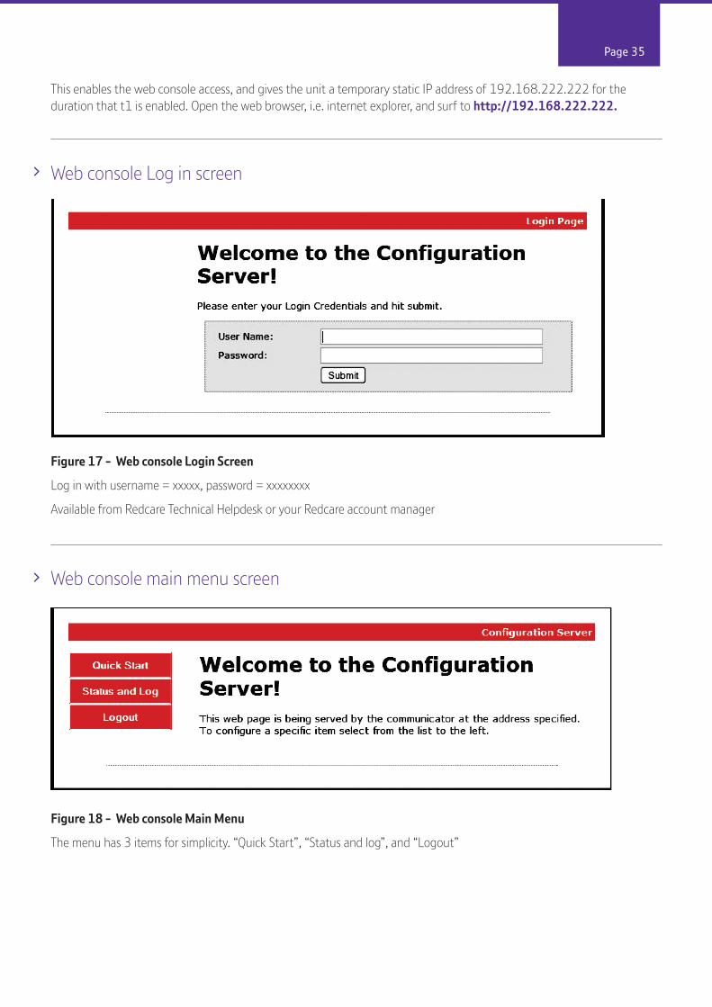
This enables the web console access, and gives the unit a temporary static IP address of 192.168.222.222 for the duration that t1 is enabled. Open the web browser, i.e. internet explorer, and surf to http://192.168.222.222.
Web console Log in screen
Figure 17 - Web console Login Screen
Log in with username = xxxxx, password = xxxxxxxx
Available from Redcare Technical Helpdesk or your Redcare account manager
Web console main menu screen
Figure 18 - Web console Main Menu
The menu has 3 items for simplicity. “Quick Start”, “Status and log”, and “Logout”

Page 36
Web console Quick Start Menu screen
Figure 19 - Web console “Quick Start” page
The web console “quick start” page in Fig. 17 is shown populat-ed with the factory defaults.
Clicking on the “Save Config” button, at the bottom of the screen, sends the configuration to the unit and then restarts the unit.
Page 37
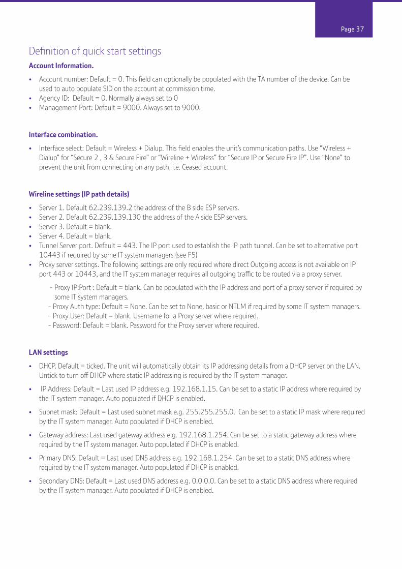
Definition of quick start settingsAccount Information.
• Account number: Default = 0. This field can optionally be populated with the TA number of the device. Can be used to auto populate SID on the account at commission time. • Agency ID: Default = 0. Normally always set to 0• Management Port: Default = 9000. Always set to 9000.
Interface combination.
• Interface select: Default = Wireless + Dialup. This field enables the unit’s communication paths. Use “Wireless + Dialup” for “Secure 2 , 3 & Secure Fire” or “Wireline + Wireless” for “Secure IP or Secure Fire IP”. Use “None” to prevent the unit from connecting on any path, i.e. Ceased account.
Wireline settings (IP path details)
• Server 1. Default 62.239.139.2 the address of the B side ESP servers.• Server 2. Default 62.239.139.130 the address of the A side ESP servers.• Server 3. Default = blank. • Server 4. Default = blank. • Tunnel Server port. Default = 443. The IP port used to establish the IP path tunnel. Can be set to alternative port 10443 if required by some IT system managers (see F5)• Proxy server settings. The following settings are only required where direct Outgoing access is not available on IP port 443 or 10443, and the IT system manager requires all outgoing traffic to be routed via a proxy server.
- Proxy IP:Port : Default = blank. Can be populated with the IP address and port of a proxy server if required by some IT system managers. - Proxy Auth type: Default = None. Can be set to None, basic or NTLM if required by some IT system managers. - Proxy User: Default = blank. Username for a Proxy server where required. - Password: Default = blank. Password for the Proxy server where required.
LAN settings
• DHCP. Default = ticked. The unit will automatically obtain its IP addressing details from a DHCP server on the LAN. Untick to turn off DHCP where static IP addressing is required by the IT system manager.
• IP Address: Default = Last used IP address e.g. 192.168.1.15. Can be set to a static IP address where required by the IT system manager. Auto populated if DHCP is enabled.
• Subnet mask: Default = Last used subnet mask e.g. 255.255.255.0. Can be set to a static IP mask where required by the IT system manager. Auto populated if DHCP is enabled.
• Gateway address: Last used gateway address e.g. 192.168.1.254. Can be set to a static gateway address where required by the IT system manager. Auto populated if DHCP is enabled.
• Primary DNS: Default = Last used DNS address e.g. 192.168.1.254. Can be set to a static DNS address where required by the IT system manager. Auto populated if DHCP is enabled.
• Secondary DNS: Default = Last used DNS address e.g. 0.0.0.0. Can be set to a static DNS address where required by the IT system manager. Auto populated if DHCP is enabled.

Page 38
Wireless Interface settings. (Wireless)
• Server 1. Default 10.18.43.211 the address of the A side ESP servers.• Server 2. Default 10.18.43.195 the address of the B side ESP servers.• Server 3. Default = blank. • Server 4. Default = blank. • Username. Default = BT Redcare.bt.com. The Wireless network username. Only used if Sim override = Off.• Password. The Wireless network password. Only used if SIM override = Off.• APN. The Wireless APN. Only used if SIM override = Off.• Smart roaming. Default = ticked. Use smart roaming if supported by the SIM when ticked.• SIM Overide: Default = Presets 1. Automatically detect the sim type and use the hard coded Wireless settings that match. Off = use the Wireless settings in the above (Username/ password/APN) fields.• Roaming CSQ limit. Default = 19. Following unit startup, if the signal strength is less than this value, then roam through the available networks until this value is exceeded or all available networks have been attempted. (CSQ19 = -75dB).• Roaming Session limit. Default = 8640 (minutes). If the previous Wireless session was longer than this time then the roaming algorithm will initially try to re-connect to the previous network. Else the unit will try the next available network. (8640mins=6 days).
Dial Up settings.
• Server 1. Default 10.18.43.195 the address of the B side ESP servers.• Server 2. Default 10.18.43.211 the address of the A side ESP servers.• Server 3. Default = blank. • Server 4. Default = blank. • Predial number; default = blank. Any additional digits that may be required to be dialled. i.e. 9 to obtain an outside line on PABX, 1740 to force CLI on, 1280 to force BT routing.• Phone Number 1. Default = 08009173263. Telephone number of A side ESP servers.• Phone number 2. Default = 08009173265. Telephone number of B side ESP servers.• Username. Default = BT [email protected]. Username for dialup RAS• Password. Password for dial up RAS.• Voltage fail delay. Default = 120s. Delay time before loss of PSTN voltage is reported. (Pin 955 alarm). Also delay time before GPOP1 operates for loss of PSTN voltage.• Voltage restore delay. Default = 30s. Delay time before restore of PSTN voltage is reported. (Pin 955 restore). Also delay time before GPOP1 restores for restoration of PSTN voltage.
Panel settings
• Ultra alarm format = Contact ID. Events generated by the secure unit are sent to ARC in this format. (Note: dial capture events are sent as they arrive from panel)• Kiss Off /Ack window. Default = 0 ms. Allows the dial capture kiss off time to be extended. (0 - 2000 ms). i.e. HKC panels may require 1850ms. • Off line timeout. Default = 1500 minutes. Unit will reboot if no polls are received from ESP over any path for this period of time. (1500mins = 25 hours)• Mains Fail time. Default = 7 minutes. Time delay before pin 13 alarm is reported.• Low DC fail time. Default = 1 minute. Time delay before Low supply voltage alarm is reported. (pin 985 alarm) Callback number. Default = Blank. (For future use of panel initiated UDL) • Serial panel type. Select the panel type for a serial 232 or 485 connection.

Page 39
General Purpose input sense settings.
Tick for positive applied triggering. Untick for positive removed triggering.
• Inputs 1-8 (Default all ticked, pos applied)• Inputs 9-16 (Default all ticked, pos applied)
End of line mode inputs 1-8.
The first 8 alarm inputs (PINS) can be set to the following modes.Standard 2 state mode. (Alarm & Restore)Single end of line mode (Alarm, Restore & Cut)Dual End of line mode (Alarm, Restore, Cut & Short)
This allows the Secure unit to monitor the wiring to the alarm panel contacts. Wire the inputs as shown below.

Page 40
To enable Dual End of Line Mode
• EOL 1-8. Tick to select end of line mode (Default all unticked)• Dual EOL mode, Tick to set the selected pins for EOL to dual EOL mode (Default unticked)• GPIP Sense is ignored on any pins selected for EOL or DEOL
Ensure that Dual EOL is ticked and EOL is ticked for each of the pins required in the example above Pin 1 and Pin 8 have been enabled for this.
Note it is only available on pins 1 – 8
Line Fault Debounce time.
• Wireline. Default = 2 mins. Time before GPOP1 will operate following IP path failure.• Wireless. Default = 15 mins. Time before GPOP1 will operate following Wireless path failure.• Dial IP. Default = 15 mins. Time before GPOP1 will operate following PSTN path failure.
(Note: GPOP1 will restore immediately following path restoral).

Page 41
General Purpose Outputs
• GPOP1 Type. Default = BSIA form 175.
- BSIA form 175. Operate on either path fail, and respond to panel interrogation on pin 11.
- Standard line Fault 1. Operate on either path fail. – (Default on Secure Fire products)
- Standard line fault 2. Operate on both paths fail
- Primary path fault. Operate when the primary path fails. (use with GPOP2).
• GPOP2 Type. Default = Relay 2 control.
- Relay 2 control
- Secondary path fault. (use with GPOP1).
- Fire (GP1) NAK. Activate when no pin 1 ack is received within 80s (Default on Secure Fire products)
• GPOP2 Mode. Default = Toggle. (This option only available if GPOP2 type is set to Relay 2 control)
- Toggle = GPOP2 follows on and off commands from ARC.
- Pulse 1 - 10s = GPOP2 pulses for a set duration with each ARC command
• GPOP3 Type. Default RPS (Return path signalling)
- Relay 1 control
- RPS
- Fire (GP1) Ack. Activate when a pin 1 Ack is received. Deactivate on pin 1 restore. (Default on Secure Fire products)
• GPOP3 Mode. Default = Toggle. (This option only available if GPOP3 type is set to Relay 1 control)
- Toggle = GPOP3 follows on and off commands from ARC.
- Pulse 1 - 10s = GPOP3 pulses for a set duration with each ARC command
• GPOP1-3 sense. Default = 1&3 ticked. Tick for low when normal and high when operated. Untick for high when normal and low when operated. (GPOP 1 is unticked and GPOP 2 & 3 ticked is the default for Secure Fire products)
• Galaxy mode for GPOP1&2. Default = unticked.
- Unticked = GPOP1 & 2 have an internal 10K pull up resistor.
- Ticked = GPOP1 & 2 have an internal 1K series resistor and no pull up.

Page 42
Galaxy modeWhen the galaxy mode checkbox is ticked then GPOP1 & 2 can directly drive a zone input on a Honeywell Galaxy panel by connecting the GPOP output through a 1K resistor to the galaxy zone input. See Fig 18.
Fig 21 - GPOP set to Galaxy mode on web console. Connect to panel via 1K resistor.
Web console status and log screen
Figure 22 - Web Console “Status and log” screen

Page 43
The status and log screen shows the current system status, and access to the unit’s event history.
The Event log history is extensive and will go back further than the last unit re-start. (i.e. the event history is stored in flash memory and not cleared by loss of power). The event log will store a minimum of 1025 events.
Events that are generated while the time on the unit is not set, i.e. after the unit has been powered up but before the unit has communicated with the ESP to obtain the correct time, are time stamped with the pseudo time and date in the year 2000 as per Fig. 18.
Note that events logged while the unit’s time has been synchronised will use Greenwich Mean Time (GMT).
When a PSTN call is attempted and fails to establish, a “Fail to communicate” event is logged in this local log. For further debugging there is a “Device number” associated. i.e. Device 0/2 means the unit failed to dial the second telephone number.
Other typical messages that may appear in the log.
Telephone line restore. Device 0 PSTN has successfully dialled up after a fail.Fail to communicate. Device 0/1 PSTN call to Telephone number 1 failedFail to communicate. Device 0/2 PSTN call to telephone number 2 failed
Panel Upload Download.Remote access to the alarm panel can be achieved using the BT Redcare UDL facility. Contact your BT Redcare representative for details of accessing the BT Redcare UDL servers.

Page 44
Roaming SIMsThe unit will auto detect the sim type that is present in the unit. Most units are supplied pre fitted with a Roaming Sim. Where a Roaming Sim is fitted then the unit will switch between Wireless networks to maintain connectivity should connectivity be lost on the current network.
The unit will search the available networks for a signal stronger than the “Roaming CSQ limit” at unit start up. (Default 19)
Should the unit lose connectivity with the BT Redcare platforms, or lose registration with the current base station, then the unit will roam onto the next available Wireless network.

Accessories

Page 46
Dial capture boardThe dial capture board is a module that can be added to a BT Redcare Secure Mk3 unit to enable interfacing with an alarm panel’s digital communicator. The alarm panel can then send SIA, CID or Fast Format messages through the Secure Mk3 unit to the Alarm receiving centre.
The dial capture board can also be used for upload download UDL allowing remote access with some types of alarm panel.
Fitting the dial capture board.• Power down the Secure Mk3 unit.• Use an ESP strap to provide electrostatic protection to the circuit boards. • Remove the plastic cover by releasing the 6 clips on the rear of the Secure Mk3 unit with a small screwdriver.• Remove the Printed circuit board PCB from the plastic base.• Identify the 20 way connector J202 and the 6 way connector J801 on the secure Mk3 unit.• Line up the 20 pins of J100 and the 6 pins of J200 on the dial capture board.• Ensure that the dial capture board is correctly aligned and press fully into the connectors.• Insert the screw through the hole in the rear of the PCB and gently tighten to hold the dial capture board in place. (Do not over tighten)• Re-assemble the Secure unit and replace the plastic cover.

Page 47
The secure unit will auto detect the dial capture board at power up. For most installations no additional configuration is required.
Connect the alarm panel’s digital communicator line connections to the terminals marked Panel A, Panel B on the secure Mk3 unit. The unit is not polarity conscious.
Configure the alarm panel digital communicator to dial 29 and use the last 4 digits of the TAID as the account number.
The dial capture board will auto detect the panel protocol as events are sent from the alarm panel. SIA, CID or FF.
Note some early Secure Mk3 units may have taller connectors J202 and J801 preventing securing with the screw and fitting of the plastic cover.
Secure Relay moduleThe Secure Relay Module is used to provide relay contacts for the Secure Mk3 unit outputs. This option is available for applications that require Normally Open (N/O) or Normally Closed (N/C) metallic contacts such as fire alarm panels.
Figure 25 – Secure Relay module fitted to the secure Mk3 unit
The secure relay module must be mounted on the Secure unit using the sticky pads provided and the correct supply voltage selected with link J7.
The relay module is fitted as standard on Secure Fire products
Full instructions for the relay module are supplied with the module 230249-HB Edition 01.
Page 48
Third Party Certification and use of Secure Fire IP and Secure Fire for both Fire andIntruder alarm signalling ( Dual linking)Secure Fire IP and Secure Fire have third party certification for both Fire (A mandatory requirement of the Construction Products Regulation (CPR) for products connected to fire alarm systems) and Intruder alarm signalling systems to LPS 1277 V3.0.
This now gives the opportunity to use one device for both systems subject to the installation meeting the relevant standards.
As well as the certification the Secure Fire IP and Secure Fire products have the ability to monitor the wiring interconnections on pins 1 - 8, a requirement when the signalling device is fitted remote to the fire panel. The units will also accept a 12v pin input to its General Purpose inputs (GPIP) whilst being powered from a 24v supply (0v common required between power supplies)
• Third party certification for both intruder and Fire• Interconnection monitoring available on pins 1 – 8 using dual end of line resistors• GPIP will accept both 24V and 12 V inputs• Power supply and enclosures must meet relevant standards• Wiring must meet relevant standards• Secure Fire IP Grade 4 signalling (enhanced ATS 5)• Secure Fire Grade 3 signalling ( Enhanced ATS 4)
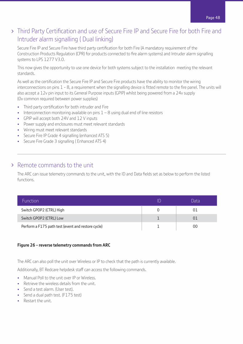
Remote commands to the unitThe ARC can issue telemetry commands to the unit, with the ID and Data fields set as below to perform the listed functions.
Figure 26 - reverse telemetry commands from ARC
The ARC can also poll the unit over Wireless or IP to check that the path is currently available.
Additionally, BT Redcare helpdesk staff can access the following commands.
• Manual Poll to the unit over IP or Wireless. • Retrieve the wireless details from the unit.• Send a test alarm. (User test). • Send a dual path test. (F175 test)• Restart the unit.
Switch GPOP2 (CTRL) High 0 01
Switch GPOP2 (CTRL) Low 1 01
Perform a F175 path test (event and restore cycle) 1 00
Function ID Data

Page 49
Description Pin CID (zone) SIA (zone) FF (zone) Time to Active
Low DC Input Level 985 302 (999) YT/YR 6 (2) E – 1 minute; R – 1 minute
PSTN voltage fail 955 356 (999) LT/LR 6(5) E – 120s; R – 30s
Inputs 1-16 1-16 323 (901-916) UA/UR (901-916) 7 (1) E – Immediate; R – Immediate
BSIA 175 Test 988 354 (998/999) TX/TE 6 (3) E – Immediate; R – Immediate
Unit Restarted 984 305 (995) AT/AR (995) 5 (6) E – Immediate; R – Immediate
Panel Download 993 628 (999) LB/LX (999) E – Bypass on; R – Bypass off E – UDL start; R – UDL end
User Test n/a 354 (997) TX(998) E – Immediate
Panel Connection n/a 356 (997) NT/NR (993) E – Immediate / R - Immediate(RS485)
Inputs 1-8 cut alarm n/a 325 (901-908) UT/UJ (901-908) E – Immediate / R - Immediate
Inputs 1-8 Short Alarm n/a 324 (901-908) UB/UU (901-908) E – Immediate / R - Immediate
Alarm List
Figure 27 - Alarms signals as delivered to ARC

Page 50
Secure IP and Secure Fire IP
Secure IP (Grade 4 only) and Secure Fire IP specification notesIP Protocol: TCP
Port: 443 or 10443
Data Usage / RequirementsPolling is every 30 seconds. A poll and response results in 288 total bytes transferred (incl IP headers). A small number of alarms will also typically be generated per day and these result in 296 bytes transferred. Overall this generates approximately 800 K Bytes per day, per site.
Traffic DirectionThe Secure unit establishes an outgoing TCP connection from your network to the BT Redcare Enterprise Services Platform (ESP). Once this outgoing TCP connection has been established, traffic over that connection is 2 way.
Additional ProtocolsOnly TCP is required from your network.
Port ForwardingNo ports need to be forwarded in the incoming direction. The outgoing TCP connection connects to port 443 or 10443 on the BT Redcare ESP network, so you would need to allow outgoing access to port 443 or 10443 if you block that by default.
NAT: Not required
Wireless RequirementsYou do not need to route Wireless traffic. The Wireless connection from the Secure IP and Fire IP communicators through to the BT Redcare ESP and on to the ARC is entirely independent of your network.
DHCP and Static AddressingThe Secure IP and Fire IP communicators can be configured as either DHCP clients or with specific static IP addresses on your internal network as you prefer.

Page 51
The symbol shown here and on the product, means that the product is classed as Electrical or Electronic Equipment and should not be disposed of with other household or commercial waste at the end of its working life.
The Waste Electrical and Electronic Equipment (WEEE) Directive (2002/96/EC) has been put in place to recycle products using the best available recovery and recycling techniques to minimise the impact on the environment, treat any hazardous substances and avoid the increasing landfill.
Product disposal instructions for users:Please dispose of the product as per your local authority’s recycling processes. For more information please contact your local authority or retailer where the product was purchased.
The product may be returned to the Freepost address below:
BT SUPPLY CHAINDARLINGTON ROAD, NORTHALLERTON.NORTH YORKSHIREDL6 2PJ.
Republic of Ireland customers can return the product to any of the following addresses:
Disposal
Disclaimer
The manufacturer or his agents disclaim responsibility for any damage, financial loss or injury caused to any equipment, property or persons resulting from any use of this equipment. The manufacturer is not liable for any purely economic loss arising from any use of this equipment. All responsibility and liability in the use of BT Redcare products are assumed by the user.
This unit is designed to be used in customer premises. Use of this equipment in other locations may void warranty. This unit is not intended for use in marine environments or water borne vessels.
BT Redcare may make changes to features and specifications at any time without prior notification in the interest of ongoing product development and improvement.
BT IRELAND27 WILLSBOROUGH INDUSTRIAL ESTATECLONSHAUGHDUBLIN 17
BT IRELANDGRAND CANAL PLAZAGRAND CANAL DOCKDUBLIN 2
BT IRELANDDUNDRUM BUSINESS PARKDUNDRUMDUBLIN 14

Page 52
ADSL Asymmetric digital subscriber line (Broadband)
ARC Alarm receiving Centre
BSIA British Security Industry Association
BER Bit Error Rate (0-7, normally shown as 99 on Secure Mk3)
CSQ Carrier Signal Quality (RSSI,BER)
CTRL Control O/P (remotely controlled output)
DHCP Dynamic Host Configuration Protocol
DIN Standard mounting rail for control equipment. (Deutsches Institut Fur Normung).
DNS Domain Name Server
ESP Enterprise Services Platform (BT Redcare’s new generation alarm signalling network)
ESPUI Enterprise Services Platform User Interface. (BT Redcare’s user interface)
F175 Form 175 as issued by BSIA
GMT Greenwich Mean Time
GPIP General Purpose Input
GPOP General Purpose Output
GPRS General Packet Radio Service
IP Internet Protocol
LED Light Emitting diode (Light Indicator)
LAN Local area Network
MMCX Micro Miniature Coaxial connector
NTLM NT Lan Manager - a suite of Microsoft security Protocols
TTL Transistor Transistor Logic
Tx Transmit
PABX Private Automatic branch Exchange. (Telephone system)
PIN Parallel Input
PSTN Public switched Telephone Network
RAS Remote Access server
RSSI Received Signal strength indicator (0-31)
RPS Return Path Signalling (An output that confirms delivery of PIN 4 to ESP)
Rx Receive
SID Serial Identity number - 12 digit unique identity number of a secure unit
SIM Subscriber identity module (sim card)
Glossary of terms

Page 53
For assistance with your BT Redcare Secure installation, please contact the BT Redcare Helpdesk on 0800 800 628
Approvals
Support
LPS 1277: Issue 3Cert No. 1270cCert No. 1270d
BT Redcare, BT Plc, 81 Newgate Street, LONDON EC1A 7AJ2014Compliance to LPS 1277 v3.0 for Secure IP, Secure 3, Solo, Secure Fire IP and Secure Fire
EN 54-21:2006Alarm transmission and fault warning routing equipment for fire alarm systems Constancy or performance certificate for Construction Products Regulation0832-CPR-X0006Redcare Secure Mk3
Technical Data: see http://www.redcare.bt.com/products_services/Secure.html
The Secure unit meets the following performance parameters as per EN 54-21 Annex A, Redcare Secure - Fire installations
Secure Fire IP EN 54-21 D4 M4 T4 S2 I3 A4 Type 2
Secure Fire EN 54-21 D2 (note 1) M2 (note 1) T3 S2 I3 A4 Type 2
Product Fire Category
Transmission time
Classification
Transmissiontime
Max. Values
Reporting timeClassification
SubsitutionSecurity
InformationSecurity
NetworkAvailability
The Secure unit meets the following performance parameters as per EN 50136-1-1 for Grade 2,3 and 4 signalling. The Redcare Secure unit also meets the following performance parameters of LPS 1277 V3.0 Redcare Secure – Security installations
Product Fire Category
Transmission time
Classification
Transmissiontime
Max. Values
Reporting timeClassification
SubsitutionSecurity
InformationSecurity
NetworkAvailability
Secure IP ATS 5 D4 M4 T4 S2 I3 A4
Secure 3 ATS 4 D2 (note 1) M2 (note 1) T3 S2 I3 A4
Secure Solo ATS 3 D4 M3 T3 S2 I3 A2
Note 1Transmission times shown are worst case when running on the secondary PSTN path only. See footnote of Table A.1 in EN 54-21. When operating as a dual path system with majority of alarms sent over GPRS the transmission times met D4, M3.

Page 54
LPS 1277 Annex C
Ensure the unit is installed as per the requirements of LPS1277 ANNEX C detailed below.The following guidance on installation practices will help enhance general Alarm Transmission System (ATS) security/ resilience, avoid undue (false) path failure reports and reduce customer inconvenience.
Important Notes 1) A claim to have installed LPCB approved SPT will be invalid if this guidance has not been followed. 2) Within this guidance the word ‘shall’ indicates a mandatory requirement. Use of the word ‘should’ indicates a requirement unless practical constraints prevent compliance
Installation (alarm company) Information
Location and alarm protection of the Supervised Premises Transceiver (SPT)i) The SPT part of the Alarm Transmission Equipment (ATE), shall be located within the I&HAS Control and Indicating Equipment (CIE), or within an enclosure that shares the same mains power supply, and has the same level of battery back up and tamper protection, as is required for the associated CIE. ii) The location of the CIE, or other enclosure, containing the SPT: shall, when installed as part of a new I&HAS; be in an area provided with ‘direct alarm protection’a) and be located where it is not visible to, or readily accessible by, members of the public. should, when retro-fitted to a pre-existing I&HAS; be in an area provided with ‘direct alarm protection’a) and be located where it is not visible to, or readily accessible by, members of the public.
Alarm protection of Site Network Equipment i) ‘Site Network Equipment’ b) that can be switched off or which has a locally or remotely accessible and changeable function, (e.g. a telephone switchboard or IP router), together with Alarm Transmission Path (ATP) aerials† and network access termination points, shall be located in an area provided with ‘direct alarm protection’a).ii) Other ‘Site Network Equipment’ b), for example intermediate junction boxes, should be provided with ‘direct alarm protection’ a).Note † Where an ATP aerial cannot be located in an area readily provided with ‘direct alarm protection’a) and still achieve the recommended minimum signal strength for adequate performance, it may be installed elsewhere (preferably indoors but otherwise outdoors), subject to positioning it where its discovery and/or ready access by intruders is considered unlikely.
Connections between the SPT and Site Network Equipment b) i) Any radio based ATP shall have a cable connection between the SPT and the required aerial, with all cable termination points, including those at any intermediate connections, using termination components (or housings) that protect against cable removal without the use of a tool. ii) Any landline based ATP shall have a cable connection between the SPT and the first suitable alarm transmission network termination point within the premises. This shall be made in one continuous run and use termination components (or housings) that protect against cable removal without the use of a tool.
The connection to the alarm transmission network shall be made in such a manner that where non-alarm related apparatus/services are also connected to that network, they do not prevent, or interfere with, the correct operation of the ATS.
Notes a) The phrase 'direct alarm protection' shall mean that sufficient detection devices are installed to ensure that, when the I&HAS is set, access to the protected equipment results in a full (e.g. a ‘confirmed’) alarm condition. Where an I&HAS uses a time delayed entry/exit route as part of the facility for unsetting, detection devices programmed to act as entry/exit route detection shall not be regarded as providing ‘direct protection’. b) The phrase ‘Site Network Equipment’ shall be regarded as all equipment installed within the alarmed premises through which signals from the SPT to the alarm transmission network beyond the perimeter of the premises are transmitted. For example, non-alarm dedicated (shared use) IP routers, telephone switchboards/Private Automatic Branch Exchanges (PABX), network access termination points, ATP aerials and communication network junction boxes/switches.

Page 55
ARC/ATS message holding Where the Alarm Receiving Centre (ARC) and/or ATS provider offers, or requests use of, a facility to block the receipt of, or hold information relating to, ATS fault notification signals or messages pending receipt of further alarm information (e.g. pending the designation of a confirmed alarm as per BS 8243), agreement to such an action shall be confirmed in writing by the customer (end user); with the relevant notification stating that this action is compatible with the risk assessment and/or the requirements of any interested party, for example an insurer. In such cases the installer shall make suitable arrangements, which shall be confirmed in writing, for the customer to be alerted to any such ATS fault notification signals/messages when their alarm system is next unset, or after a period of 96 hours, whichever is the sooner.
Installers shall advise the customer :-
i) of any potential for normal ATS functions, including normal or ‘stepped up’ checking of ATS availability (e.g. by sending test signals), which could interfere with, or prevent use of, any non-alarm related apparatus/services connected to a telephone line shared with the ATS. In such cases customers should be recommended to consider use of an ex-directory 'In Coming Calls Barred' (ICCB) telephone line dedicated to ATS use.
ii) of the adverse effect on reliable operation of their intruder alarm system that may result where ‘Site Network Equipment’ b) used by the ATS:- could have its correct operation/settings locally or remotely accessed and changed/disabled, for example a non-alarm dedicated (shared use) IP router. In such cases customers should be recommended to consider protection against unauthorised access by the use of an access password (not the factory default) and, if their equipment has wireless connectivity having the wireless network Access Point Name (APN) hidden. would cease to work in the event of loss of mains power; for example a Private Automatic Branch Exchange (PABX) or non-alarm dedicated (shared use) IP Router. In such cases customers should be recommended to consider protecting the power supply against disconnection by use of an unswitched fused spur connection or by having such equipment or its power supply connections located in an area/room to which unauthorised access is restricted.
iii) of the adverse effect on reliable operation of their intruder alarm system that may result from cessation of any communication service(s) necessary for correct operation of the ATS; for example telephony services such as ‘three way calling’ (Star Services) or access to internet services (via an ISP). In such cases customers should be recommended to take steps to ensure that availability of these services is maintained at all times when their alarm system is likely to be in use.
iv) that, where the performance of the SPT is capable of being changed after installation, such changes shall be confirmed in writing by the customer; with the relevant notification stating that any such change is compatible with the risk assessment and/or the requirements of any interested party, for example an insurer.
To find out more about Redcare:
call us free on 0800 800 628*or email [email protected]
© British Telecommunications 2017.Registered office: 81 Newgate Street, London, EC1A 7AJRegistered in England no. 1800000
PHME 79774 19 June2017