installation, maintenance and operation manual - samm · pdf filetypical configuration for...
TRANSCRIPT

Installation, Maintenance and Operation Manual
Mineral Insulated (MI)Series Heating Systems
© 2
005
Tyco
The
rmal
Con
trol
s D
OC
-586
Rev
.1 0
2/07
Prin
ted
in B
elgi
um o
n ch
lorin
e-fr
ee b
leac
hed
pape
r
General information 4
Heating cable selection and storage 7
Heating cable installation 9
Components selection and installation 23
Temperature control and limitation 24
Thermal insulation and marking 27
Power supply and electrical protection 31
System testing 32
Operation, maintenance and repairs 33
Trouble Shooting 34
Installation Record Sheet 35
1
2
3
4
5
6
7
8
9
10
11

Typical configuration for MI-heating cable system (single conductor)
Typical configuration for MI-heating cable system (dual conductor)
Junction box
MI cold lead cable (single conductor)
Circuit identification tag
Hot/cold joint
MI cold lead cable (dual conductor)
Hot/cold joint
Circuit identification tag
Junction box
Dual conductor MI heating cable
End cap
Loop of MI heating cable (single conductor)

General information
Use of the manual
This Installation and Maintenance manual applies to Tyco Thermal Controls Mineral Insulated (MI) series resistance heating cable systems installed on thermally insulated pipes and vessels and associated equipment. In particular it refers to mineral insulated (MI) series heating systems, which feature a specific power output depending on various design parameters, in particular, cable length and voltage. This manual provides general information and shows an overview of the most common installations and applications on MI as well as typical examples. In any case the information provided for specific projects will take precedence over this manual. In case of conflicts, please contact your Tyco Thermal Controls representative. Tyco Thermal Controls offers two different cable construc-tions for electrical heat-tracing purposes: single conductor cables, which are typically laid in loop configurations and dual conductor cables, which are typically laid in single runs.
Figure 1: Typical cable construction
Various types of the MI bulk heating cables are available: HCC/HCH: Copper sheathed MI heating cables HDF/HDC: Cupro-nickel sheathed MI heating cables HSQ: Stainless steel sheathed MI heating cables HAx: Alloy 825 sheathed MI heating cables HIQ: Inconel sheathed MI heating cables
Figure : Typical heating unit designs
Design type B Single conductor
Heating conductor(s)
Insulation (magnesium oxide)
Single-conductor cable
Dual-conductor cable
Metal sheath Metal sheath
Potted seal
Heating cable length
Hot/cold joint
Cold lead cable (standard 2 m)
300 mmFlexible
tail length
Gland
1

Design type D Dual conductor
Design type E Dual conductor
The joints can be either brazed or laser welded, refer to Tyco Thermal Controls product literature for more detailed information.
Please note that this manual only covers the installa-tion of pre-fabricated MI heating units. The complete termination process and repair of heating cable units is not covered by this manual and must be carried out by qualified and experienced personal only.
For more information contact your Tyco Thermal Controls representative.
ImportantFor the Tyco Thermal Controls warranty to apply, the instructions of this manual must be followed. Design, installation, inspection, operation and maintenance must be in accordance with the standards IEC 6019, IEC 6086, EN 0019 and EN60079-7 (where applicable). Other local requirements and national electric codes applicable to electrical heat-tracing systems must be followed as well. The thermal safety class is (to IEC 6019-).
Personal involved in the installation, testing and mainte-nance of electric heat-tracing systems must be suitably trained in all special techniques required, as well as in general electrical installation work. All work should be monitored by supervisors experienced in heat-tracing applications.
300 mmFlexible
tail length
Potted seal
Heating cable length
Hot/cold joint GlandEnd cap
Cold lead cable (standard 2 m)
300 mmFlexible
tail length
Potted seal
Heating cable length
Hot/cold joint Gland
Cold lead cable (standard 2 m)

6
Area Classification – Ordinary
HCC/HCH/ HDC/HDF/HSQ/HAx/HIQ
Area Classification – Hazardous, Zone 1 or Zone
Special conditions for safe use in hazardous area:Please refer to relevant hazardous area certifications
Certificate No. Code Nos.
HCC/HCH/HDC/HDF/HSQ/HAx/HIQ (heating elements) Baseefa 02ATEX0046X II 2 G EEx e II T6 to T1
HCC/HCH/ HDC/HDF/HSQ/HAx/HIQ (bulk cable) Baseefa 02ATEX0045U II 2 G EEx e II T6 to T1
For other national approvals please contact Tyco Thermal Controls.
The order reference of MI heating units uses the following nomenclature
When ordering, the complete order reference of the MI heating unit needs to be provided. For hazardous areas, information must also be provided about the T-rating and temperature data relevant to the application (max. sheath temperature data) to enable the correct representation of data on hazardous area tags attached to the completed heating unit in the factory. Before installation, check the suitability of the heating units supplied. Changes to any of the parameters may require a re-design and must be confirmed before installation.
B/HSQ1M1000/43.0M/1217/230/2.0M/SC1H2.5/X/M20/EX
Area classification: EX, ORD Gland size M20, M25, etc... Hot/cold joint material type: X -stainless steel, Y - brass, LW - laser welded Cold lead size and sheath type (see table on next page) Cold lead length: M for unit in meters (standard is 2 m) Heating unit: Operating voltage Heating unit: total wattage in W Unit length: M for unit in meters Heating cable reference Heating cable unit type: Type B, D or E
7
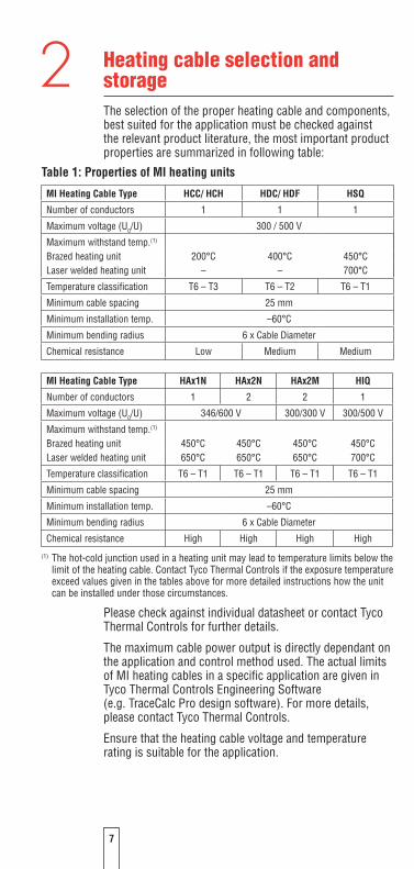
Heating cable selection and storageThe selection of the proper heating cable and components, best suited for the application must be checked against the relevant product literature, the most important product properties are summarized in following table:
Table 1: Properties of MI heating units
Please check against individual datasheet or contact Tyco Thermal Controls for further details.
The maximum cable power output is directly dependant on the application and control method used. The actual limits of MI heating cables in a specific application are given in Tyco Thermal Controls Engineering Software (e.g. TraceCalc Pro design software). For more details, please contact Tyco Thermal Controls.
Ensure that the heating cable voltage and temperature rating is suitable for the application.
MI Heating Cable Type HCC/ HCH HDC/ HDF HSQ
Number of conductors 1 1 1
Maximum voltage (U0/U) 300 / 500 V
Maximum withstand temp.(1)
Brazed heating unit 200°C 400°C 450°CLaser welded heating unit – – 700°C
Temperature classification T6 – T3 T6 – T2 T6 – T1
Minimum cable spacing 25 mm
Minimum installation temp. –60°C
Minimum bending radius 6 x Cable Diameter
Chemical resistance Low Medium Medium
2
MI Heating Cable Type HAx1N HAxN HAxM HIQ
Number of conductors 1 2 2 1
Maximum voltage (U0/U) 346/600 V 300/300 V 300/500 V
Maximum withstand temp.(1)
Brazed heating unit 450°C 450°C 450°C 450°CLaser welded heating unit 650°C 650°C 650°C 700°C
Temperature classification T6 – T1 T6 – T1 T6 – T1 T6 – T1
Minimum cable spacing 25 mm
Minimum installation temp. –60°C
Minimum bending radius 6 x Cable Diameter
Chemical resistance High High High High
(1) The hot-cold junction used in a heating unit may lead to temperature limits below the limit of the heating cable. Contact Tyco Thermal Controls if the exposure temperature exceed values given in the tables above for more detailed instructions how the unit can be installed under those circumstances.
8
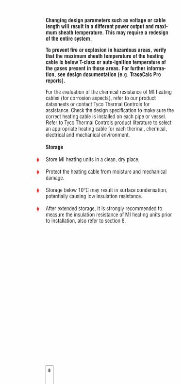
Changing design parameters such as voltage or cable length will result in a different power output and maxi-mum sheath temperature. This may require a redesign of the entire system.
To prevent fire or explosion in hazardous areas, verify that the maximum sheath temperature of the heating cable is below T-class or auto-ignition temperature of the gases present in those areas. For further informa-tion, see design documentation (e.g. TraceCalc Pro reports).
For the evaluation of the chemical resistance of MI heating cables (for corrosion aspects), refer to our product datasheets or contact Tyco Thermal Controls for assistance. Check the design specification to make sure the correct heating cable is installed on each pipe or vessel.Refer to Tyco Thermal Controls product literature to select an appropriate heating cable for each thermal, chemical, electrical and mechanical environment.
Storage
D Store MI heating units in a clean, dry place.
D Protect the heating cable from moisture and mechanical damage.
D Storage below 10°C may result in surface condensation, potentially causing low insulation resistance.
D After extended storage, it is strongly recommended to measure the insulation resistance of MI heating units prior to installation, also refer to section 8.

9
Heating cable installation
Warning
As with any electrical equipment or wiring installation that operates at line voltages, damage to heating cable and components, or incorrect installation that allows the penetration of moisture or contamination can lead to electrical tracking, arcing and potential fire hazard. In case of damage and later repair on site any unconnected heating cable end, exposed to the environment, must be sealed appropriately.
.1 Pre-installation checks
Check design recommendations:
D Verify that you have all required engineering documents supporting the installation
D Check for any special instructions in engineering documen-tation (e.g. cover with aluminium foil, use of metal mesh, fixation etc...).
D Verify that hazardous area information given in engineering documentation is compatible with the area classification the material will be installed in.
Check materials received:
D Inspect heating cable and components for in-transit damage.
D Review the heating cable design and compare the list of designed materials to the catalogue numbers of heating cables and electrical components received to confirm that proper materials have been received on site. The heating cable type and hazardous area marking (if applicable) is printed on a tag label supplied with each heating element.
D Measure and note down the electrical resistance and the insulation resistance of the cable. Compare these values to those in the design documents (see section 8).
Check equipment to be traced:
D Check identification, length and diameter of pipework/ vessel against the design documents. Also verify, that actual temperatures and insulation properties are in align-ment with the design documentation.
D Ensure all pressure testing of pipework/ vessel is complete and final paint and pipe coatings are dry to touch.
3

10
D Walk the system and plan the routing of the heating cable on the pipe, including tracing of heat sinks. e.g. valves, flanges, supports, drains etc.
D Inspect piping for burrs, rough surfaces, sharp edges etc. which could damage the heating cable. Smooth off or cover with layers of aluminium foil. At elevated sheath temperatures consider the use of stainless steel foil. (e.g. HSQ; HIQ or HAx).
D Surface areas where heat-tracing is to be installed must be reasonably clean. Remove dirt, rust and scale with a wire brush and oil and grease films with a suitable solvent.
. Heating cable pulling and laying
Heating cable pulling tips:
Figure : Importance of cable pulling direction
D Avoid distortion of the cable and kinking. D When pulling the heating cable, avoid: d sharp edges d excessive pulling force d kinking and crushing d running over it with equipment.
The minimum bending radius of the heating cable must be respected.

11
Figure : Minimum bending radius of MI heating cables
D Do not repeatedly bend and straighten the cable.
D Keep heating cable strung loosely but close to the pipe being traced, to avoid interference with supports and other equipment.
D Add additional heating cable to trace the fittings and supports as required by the design specification or engineering documents.
D Leave the appropriate amount of heating cable at all power connection, splice and tee locations.
D Do not bend the cable within 150 mm of the hot to cold junction or remote terminations.
D When installing MI and other constant wattage heating cables, ensure that they do not overlap or cross. Doing so may lead to local over-heating and hazard of fire.
Figure : Minimal spacing must be respected
Minimum cable spacing: 25 mm (lower spacings may be possible but require special attention and must be properly documented in the engineering documentation).
For installation in hazardous areas, the standard mini-mum spacing is 0 mm. This must be respected, unless lower spacings are specifically allowed in the engineering documentation.
6 x ∆
Cable ∆ > 6 mm

1
Table : Typical allowances (in mm) per run of cable
NPSinch
DNmm
Light valve
(flanged)
Light valve (threaded or welded)
Heavy valve
(flanged)
Heavy valve (threaded or welded)
Typical pipe shoe
Flange pair
Field vari-ance
0.5 15 300 300 300 300 910 300 2%
0.75 20 460 300 460 300 910 300 2%
1 25 610 300 610 300 910 460 2%
1.5 40 760 460 910 460 910 460 2%
2 50 760 610 1060 610 910 460 2%
3 80 910 760 1220 760 910 610 3%
4 100 1220 910 1520 910 910 610 3%
6 150 1520 1060 1830 1060 910 610 3%
8 200 2140 1220 2440 1220 910 610 3%
10 250 2440 1520 3050 1520 910 910 3%
12 300 2750 1830 3660 1830 910 1060 3%
14 350 3050 2140 4270 2140 1370 1220 3%
16 400 3350 2440 4880 2440 1370 1370 3%
18 450 3660 2750 5500 2750 1370 1680 3%
20 500 3970 3050 6100 3050 1370 1830 3%
24 600 4580 3660 7320 3660 1370 2140 3%
1. Allowances above are based on typically available fittings and sup-ports, with an insulation thickness equivalent to the pipe insulation. Please refer to the engineering documentation for project specific allowances.
2. For pipes requiring more than one run of heating cable, apply the full allowance for each run of cable on each fitting or support as long as space allows. However, MI heating cables must not touch or overlap and the minimum spacing between the heating cables must be respected.
3. For some applications, it may be physically impossible to install all of the recommended heating cable directly on the fitting or support. In this case, install the excess heating cable on the pipe, on either side of the fitting or support, or distribute the additional heater length along the entire circuit length if a lower local temperature is acceptable. This constraint may be difficult for small pipes and/or multiple cable runs. If required, contact Tyco Thermal Controls for assistance.
4. The field variance is important to accomodate expansion and contraction of the heated equipment. Also refer to figures 12-14 for more detailed information.
1
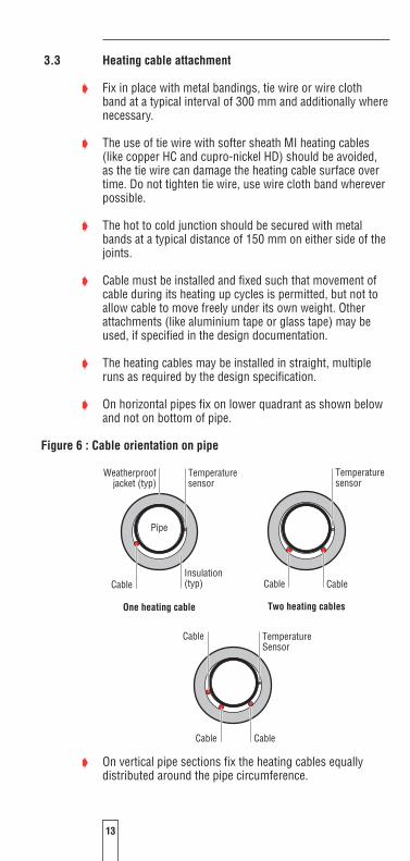
. Heating cable attachment
D Fix in place with metal bandings, tie wire or wire cloth band at a typical interval of 300 mm and additionally where necessary.
D The use of tie wire with softer sheath MI heating cables (like copper HC and cupro-nickel HD) should be avoided, as the tie wire can damage the heating cable surface over time. Do not tighten tie wire, use wire cloth band wherever possible.
D The hot to cold junction should be secured with metal bands at a typical distance of 150 mm on either side of the joints.
D Cable must be installed and fixed such that movement of cable during its heating up cycles is permitted, but not to allow cable to move freely under its own weight. Other attachments (like aluminium tape or glass tape) may be used, if specified in the design documentation.
D The heating cables may be installed in straight, multiple runs as required by the design specification.
D On horizontal pipes fix on lower quadrant as shown below and not on bottom of pipe.
Figure 6 : Cable orientation on pipe
D On vertical pipe sections fix the heating cables equally distributed around the pipe circumference.
Weatherproofjacket (typ)
Insulation(typ)Cable
Pipe
One heating cable
Cable
Cable Cable
Cable
Two heating cables
Cable
Temperaturesensor
Temperaturesensor
TemperatureSensor

1
D Read the design documents, in particular concerning the need for cable allowances and regard the location of junc-tion boxes/controllers before permanently attaching the cable to the pipe.
D Verify if the design documentation requires that the heating cables have to be covered by aluminium or stainless steel foil before the insulation is applied.
D Installation on tanks typically requires additional fixing devices as pre-punched steel strips as shown below:
Figure 7: Typical cable layout on large surfaces like tank walls
Figure 8: Fixing device: pre-punched metal strap
D Avoid sharp edges and properly seal penetration of MI cold lead cables through the insulation cladding.
Coldleads
Junctionbox
Temperaturecontroller
Heating cable
Temperaturesensor
Banding
Prepunchedstrapping

1
. Attachment materials
D Stainless steel pipe straps for different pipe dimensions up to 36 “ (e.g. PB 300).
D Stainless steel banding (30 m roll) together with stainless steel buckles (one per fixing) (e.g. SNLS + SNLK).
D Tie wire (e.g. RMI-TW) is especially suitable for the fixation on irregular shapes like pumps, valves etc.. The use of tie wire with softer sheath MI heating cables (like copper HC and cupro-nickel HD) should be avoided where possible, as the tie wire can damage the heating cable surface over time, use wire cloth band wherever possible. For the installation of MI heating cables on metal meshes, tie wire may be used, but must not be tighten and should allow for free movement of MI heating cable during expansion and contraction.
D Pre-punched metal banding allowing fixed heater spacing, where multiple runs of cable are applied (e.g. HARD-SPACER-SS-25MM-25M).
D Various types of metal meshes are available for installation on tanks, valves, pumps (e.g. mesh types FT-19 and FT-20)
. Typical installation details
The following details show some principles of MI cable installation, using dual conductor cables. Single conductor cables follow the same principles, but typically form a loop. Attention must be given, for single conductor configura-tions, where both ends need to be terminated in the same power supply box.
D Where feasible, uncoil the heating cable and lay it alongside the pipe section to be traced. For shorter single conductor cable, to be installed in the form of a „hairpin“, it may be advantageous to unroll the heating cable, loop it, and then lay it alongside the pipe section so that both runs of cable can be installed simultaneously.
Figure 9: Uncoiling heating cable
End cap
Hot-cold joint
Tie wire /wire cloth band
Stainless steel pipe strap, banding, tie wire, wire cloth band, etc.
Leave largebending radius (typ.)
Endcap

16
Figure 10: Attaching hot-cold joint and end cap
D Attach hot-cold joint to end of pipe nearest the power sup-ply point, and the other end of heating cable to the other end of the pipe. Support hot-cold joint by attaching cable with pipe straps/banding at a distance of 6 inches (150 mm) on either side of joint. Secure joint itself to pipe with a pipe strap/band as shown in Figure 10.
D Fasten middle of heating cable to the halfway point of pipe leaving equal slack on either side.
D Attach heating cables to pipe with pipe straps/banding, tie wire or wire cloth band at 12-18 inches (300-450 mm) intervals. Tie wire should be snug, but should not cut or indent the sheath.
The use of tie wire with softer sheath MI heating cables (like copper HC and cupro-nickel HD) should be avoided, as the tie wire can damage the heating cable surface over time, use wire cloth band wherever possible.
Figure 11: Allowances for valves, flanges, and pipe supports
D Use tie wire or wire cloth band to hold cable to irregularly shaped objects such as valves or pipe supports.
Figure 1: Installing cable on valves and pipe supports
D Allow cable to wave along pipe as per Figure 14 und 15. This allows for expansion and contraction of the heating cable as it heats up and cools down. Use up excess cable by waving along pipe and increasing amount used at each pipe support.
End cap
Hot-cold joint
Tie wire /wire cloth band
Stainless steel pipe strap, banding, tie wire, wire cloth band, etc.
Leave largebending radius (typ.)
Endcap
End cap
Hot-cold joint
Tie wire /wire cloth band
Stainless steel pipe strap, banding, tie wire, wire cloth band, etc.
Leave largebending radius (typ.)
Endcap
End cap
Hot-cold joint
Tie wire /wire cloth band
Stainless steel pipe strap, banding, tie wire, wire cloth band, etc.
Leave largebending radius (typ.)
Endcap

17
D Note: Do not use up excess cable at one location. Distribute equally along pipe.
Figure 1: Completed MI heating cable installation
Figure 1: Pipe strap spacing
Figure 1: Fastening several runs of cable
D Note: Where several heating cables are required, a
pre-punched metal strapping may aid the installation and consistent spacing of heating cables.
Stainless steel pipe straps, banding,or tie wire, wire cloth band, etc...
Drip loop
Hot-cold joint
Cold lead
Junction box
150 mm
Insulation app. 300 mm
150 mm
app. 300 mm
Use wide stainless banding(tension with hand-tensioner only)
Prepunched metal strapping
Wave cables with a minimum spacing of 25 mm to 50 mm along pipe, unless design documentation clearly states other values.
End cap
Hot-cold joint
Tie wire /wire cloth band
Stainless steel pipe strap, banding, tie wire, wire cloth band, etc.
Leave largebending radius (typ.)
Endcap
18
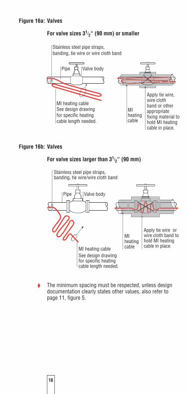
Figure 16a: Valves
For valve sizes 1/“ (90 mm) or smaller
Figure 16b: Valves
For valve sizes larger than 1/“ (90 mm)
D The minimum spacing must be respected, unless design
documentation clearly states other values, also refer to page 11, figure 5.
Pipe Valve body
Apply tie wire orwire cloth band tohold MI heatingcable in place.
MIheatingcableMI heating cable
See design drawing for specific heating cable length needed.
Stainless steel pipe straps, banding, tie wire or wire cloth band
Pipe Valve body
MI heating cable See design drawingfor specific heatingcable length needed.
MI heating cable
Apply tie wire,wire cloth band or other appropriate fixing material to hold MI heatingcable in place.
Stainless steel pipe straps,banding, tie wire/wire cloth band
Pipe Valve body
Apply tie wire orwire cloth band tohold MI heatingcable in place.
MIheatingcableMI heating cable
See design drawing for specific heating cable length needed.
Stainless steel pipe straps, banding, tie wire or wire cloth band
Pipe Valve body
MI heating cable See design drawingfor specific heatingcable length needed.
MI heating cable
Apply tie wire,wire cloth band or other appropriate fixing material to hold MI heatingcable in place.
Stainless steel pipe straps,banding, tie wire/wire cloth band

19
Figure 17: Installation at 90° elbow
Figure 18: Flanges
Steel pipe
Stainless steel pipe straps, banding, tie wire or wire cloth band(typical)
MI heating cable
MI heating cable is applied tooutside radius of elbow.
Flange
Heating cable
Apply tie wire or wire cloth band to hold
heating cable in place.
Stainless steel pipe straps,banding, tie wire or wire cloth band

0
Figure 19: Cable layout over clamps and straps
Figure 0 : Shoe and sleeve type support
D The minimum spacing must be respected, unless design documentation clearly states other values, also refer to page 11, figure 5.
Figure 1: Dummy supports
Insulation
Dummy leg
Pipe shoe
Heating cable
Stainless steel pipe straps, banding, tie wire or wire cloth band
Stainless steel pipe straps, banding, tie wire or wire cloth band (typical)
See design drawings for specific heating cable length needed.
MI heating cable Pipe
MI heating cable
Stainless steel pipe straps, banding, tie wire or wire cloth band
Pipe
Bar hanger

1
D The minimum spacing must be respected, unless design documentation clearly states other values, also refer to page 11, figure 5.
D Check drawings for dummy leg insulation.
D Pumps should have their own heating cable, separate from the connection box.
Figure : Pumps
D The minimum spacing must be respected, unless design documentation clearly states other values, also refer to page 11, figure 5.
D Cover the heating cable with metal foil or equivalent before applying insulation to ensure the cables do not become trapped in the insulation.
D General note:Trace pipe fittings as shown to allow easy maintenance.An alternative is the use of metal wire mesh cages.
Pump body
Motor Heating
cable
Junction box (series connect)
Stainless steel pipe straps,banding, tie wire or wire cloth band
Stainless steel tie wire or wire cloth band is required on both sides to hold heating cable in place.
MI heating cable
Stainless steel pipe straps, banding, tie wire or wire cloth band
Pipe
Bar hanger
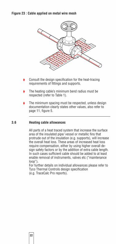
Figure : Cable applied on metal wire mesh
D Consult the design specification for the heat-tracing requirements of fittings and supports.
D The heating cable’s minimum bend radius must be respected (refer to Table 1).
D The minimum spacing must be respected, unless design documentation clearly states other values, also refer to page 11, figure 5.
.6 Heating cable allowances
All parts of a heat traced system that increase the surface area of the insulated pipe/ vessel or metallic fins that protrude out of the insulation (e.g. supports), will increase the overall heat loss. These areas of increased heat loss require compensation, either by using higher overall de-sign safety factors or by the addition of extra cable length. In such cases sufficient cable should be added to at least enable removal of instruments, valves etc (“maintenance loop”).For further details on individual allowances please refer to Tyco Thermal Controls design specification (e.g. TraceCalc Pro reports).
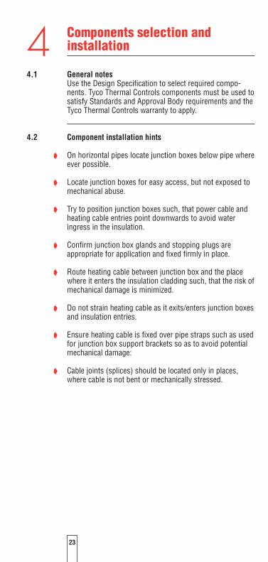
Components selection and installation
.1 General notesUse the Design Specification to select required compo-nents. Tyco Thermal Controls components must be used to satisfy Standards and Approval Body requirements and the Tyco Thermal Controls warranty to apply.
. Component installation hints
D On horizontal pipes locate junction boxes below pipe where ever possible.
D Locate junction boxes for easy access, but not exposed to mechanical abuse.
D Try to position junction boxes such, that power cable and heating cable entries point downwards to avoid water ingress in the insulation.
D Confirm junction box glands and stopping plugs are appropriate for application and fixed firmly in place.
D Route heating cable between junction box and the place where it enters the insulation cladding such, that the risk of mechanical damage is minimized.
D Do not strain heating cable as it exits/enters junction boxes and insulation entries.
D Ensure heating cable is fixed over pipe straps such as used for junction box support brackets so as to avoid potential mechanical damage:
D Cable joints (splices) should be located only in places, where cable is not bent or mechanically stressed.
4
Temperature control and limitation
.1 General rules
Tyco Thermal Controls MI series heating cables are con-stant power output heaters and as such typically requiretemperature control, unless otherwise explicitly specified. Good practice and local regulations may require addition-ally independent temperature limitation devices; The selection of such devices also depends on environmental conditions (non-haz or haz area).
D For applications in hazardous areas either a stabilized design or a thermostat control with temperature limiter complying with the requirements of IEC 62086 and EN 50019:2000 can be used to limit the surface temperature of the heating cable.
D In cases where stabilized design is not applicable, a con-trol thermostat must ensure that the heating system under normal conditions will be switched off, as soon as maintain temperature is reached.
D An additional, independent temperature limiter ensures that the surface temperature of the heating cable will not exceed the maximum allowed temperature of hazardous area if the control thermostat fails.
D A lockout function ensures that the heating cable remains switched off, until failure has been eliminated and normal conditions are restored.
D The lockout function is manually re-armed. Reset requires a tool (e.g. a key to open a panel or a password for soft-ware).
D Value of setpoint has to be secured against unintended change.
D Limiter must permanently switch off in case of sensor malfunction.
D The limiter function is tested against relevant standards (e.g. EN60730 or DIN3440 etc.).
5

D Follow the installation instructions supplied with the ther-mostat and/or the limiter.
D Use a proper wiring diagram for the heating cable layout and control method desired.
D The limiter must be set to ensure that the maximum tem-perature of the surface of the cable does not exceed either T-class or maximum working temperature of the heater for a given output under worse case conditions.
D WarningAs with any temperature measurement equipment, pos-sible falsification of true temperatures due to increased heat loss caused by the sensor itself might lead to inaccurate temperature readings or unsafe tripping of safety limiters. The setpoint might need to be adjusted accordingly.Contact Tyco Thermal Controls or the supplier of the limitation device in order to obtain detailed information concerning offsetting of limitation devices.
. Sensor placement: Temperature control device
The choice of the right location for the controller sensor depends on, but is not limited to following aspects:
D Flow direction of the fluid, best location: downstream.
D Impact of heat sinks such as supports etc, best location: close to heat sink.
D Chimney effect on large size vertical pipes, best location: on the bottom.
D Accessibility for maintenance purposes, best location: at ground level.
D Impact of other heat sources, sun etc., best location: at cold side.
For details please refer to the engineering documentation.

6
. Sensor placement: Temperature limiter device
Typically the sensor is being placed on a length of cable, that is separated from the pipe by means of insulating ma-terial, in order to create an “artificial hotspot”. The choice of the right location for the limiter sensor depends on, but is not limited to following aspects:
D Flow direction of the fluid, best location: upstream in case of warmer inrushing fluid.
D Impact of heat sinks such as supports etc, best location: away from heat sinks.
D Accessability for maintenance purposes, best location: at ground level.
D Chimney effect on large size vertical pipes, best location: at the top.
D Impact of other heat sources, sun etc., best location: at hot side of pipe.
D It is the responsibility of the installer to ensure that these conditions are met in the most appropriate way.
D For more details please refer to the engineering documen-tation.

7
Thermal insulation and marking
6.1 Pre-insulation checks
D Visually inspect the heating cable and components for correct installation and possible damage. (See Section 10 if damaged.)
D Insulation resistance testing (as per Section 8) is strongly recommended prior to covering the pipe with thermal insulation.
D Discharge cable immediately after insulation test.
6. Insulation related requirements
D Correct temperature maintenance requires properly installed and dry thermal insulation.
D The sheath temperature of an MI heating cable can be substantially above the temperature of the pipe/equipment to be traced. Verify that the max. sheath temperature of the heating cable is compatible with the insulations materials to be used. Contact your Tyco Thermal Controls repre-sentative if you have any questions.
D Check that all pipes, including fittings, wall penetrations and other areas are completely insulated.
D Thermally insulate and weatherproof to design specifica-tion.
D Ensure that heating cable is not damaged during installa-tion of cladding by drills, self tapping screws and sharp edges of cladding etc.
D In all stabilized design cases, the characteristics of the installed thermal insulation (material and thickness) must comply with the design requirements and be verified and confirmed in the documentation, to ensure compliance with approvals requirements.
D Make sure, that under no circumstances any insulation material is being placed between heated surface and cable, thus disabling intended heat flow to the substrate, which may result in possible overheating of the cable.
6

8
D Good practice requires wrapping of the installed heating system with an appropriate metal foil prior to installation of the thermal insulation. This is especially so at places where intimate contact between heat-tracing cable and heated surface is not possible, such as valves or flanges where a suitable heat sink of temperature rated metal foil and wire cloth band may be used to improve heat-transfer. Also refer to design documentation, which may specify this requirement as well as material type, thickness etc... Further details may also be described in local insulation
standards.
D Check that all HC or HD cables are mechanically protected and properly sealed at all places where they penetrate the insulation cladding.
D Ensure that all places are sealed where thermostat capil-laries, sensor cables or support brackets etc. exit the cladding.
6. Marking
D Install “Electric Traced” signs on the insulation cladding along piping at suitable intervals (3-5 m intervals recom-mended) on alternate sides as a warning.
D Mark on outside of insulation the location of any heating cable components like connection points, splices etc.
MI-Heating unit identification:
D Each MI heating unit is supplied with an identification tag with important details about the type and operation condi-tions of the unit.
D In hazardous areas, the cable tag is mandatory.
D The tag contains the area classification in addition to other relevant design information.

9
Figure : Typical MI identification tag (for use in hazardous areas)
– MI Unit Reference is the order reference following the nomenclature of MI heating units (also see page 6)
– Heating Cable Ref. is the type of MI heating cable– Element length is the heated length of the MI unit– Year of Manufacture is the manufacturing year– Circuit length (if different) informs about the “total
circuit length” in case of multiple elements being con-nected in series
– Design Temperature Class states the “T-class” or “Auto Ignition Temperature” including the “Zone” classifica-tion, which the unit is designed for
– Design method informs about the method of tempera-ture control, which has been used for the design and must be installed to control the heating unit. Examples: 1) “Stabilized” indicates that the design method used
is “stabilised design”. All parameters used in the design of the application must be respected in order to comply with the hazardous area requirements (e.g. pipe diameters, insulation thickness, process, ambient conditions ...). The reference temperature for the sheath temperature calculations is either the calculated “max. uncontrolled temperature” or the “max. process temperature”, whichever is higher.
2) “Control limited” indicates that the design method used is “control limited design”. The reference temperature for the sheath temperature calculations is the control limited set point and must be assured by the use of an alarm capable control unit making sure the heating element is switched off, when the pipe/equipment exceed this temperature. The use of a wrong control device or a change of the tempera-ture setting will invalidate the design calculation.
3) “Limiter-Lockout” indicates that the design method used assumes the installation of an approved limiter (typically a safety temperature limiter which sensor is installed on the heating cable surface using an “artificial hotspot”). The set point of the limiter must be below the T-class of the area and may require an additional down-adjustment for potential falsifying of the measured temperature, refer to the instructions given by the manufacturer of the limiter.
MI Unit Reference: B/HSQ1M1000/43M/1187/230/2M/SC1H2.5/X/M20/EXHeating Cable Ref.: HSQ1M1000 Element Length: 43 mYear of Manufacture: 2006 Circuit Length (if different):Grade: (high) Design Temperature Class: T1 Zone1 Design Method: Limiter-Lockout Maximum Withstand Temperature: 450°CMax. Sheath Temperature: 331°C Sheath Reference Temperature: 200°CNom. Power Output @ 230 V: 1187 W @ Maintain TemperatureOrder No: Customer Order No:Batch number: XXXXXX Circuit Reference:Type Examination No: Baseefa02ATEX0046X
THIS TAG MUST NOT BE REMOVEDFollow installation and operating instructions for safe use in hazardous areas!
2 G EEx e T1
1180

0
– Maximum Withstand Temperature is the max. with-stand temperature of the heating cable and the hot-cold joint used, it may also be limited by the hazardous area approval
– Max. Sheath Temperature is the max. sheath tempera-ture of the MI heating cable based on the application design data
– Sheath Reference Temperature is the reference temperature, which the “max. sheath temperature” cal-culated in the design of the system is based upon, (also see “Design Method”)
– Power Output refers to the expected power of the heat-ing unit at the specified voltage/configuration. It is based on the desired maintain temperature and may be signifi-cantly lower than during start-up phase, in particular for heating cables using conductors with a high temperature coefficient (e.g. copper conductor). Refer to the design information for proper saying of the circuit breaker and power supply.
The design calculation must always be in compliance with the application design and the ambient parameters.
Figure : Typical MI identification tag (non-hazardous areas)
MI Unit Reference: B/HSQ1M2500/11.5M/1840/230/0.5M/SC1H2.5/LW/M20/ORDHeating Cable Ref.: HSQ1M2500 Element Length: 11.5 mYear of Manufacture: 2006 Circuit Length (if different):Grade: (high)Nom. Power Output at 230 V: 1840 W @ Maintain TemperatureOrder No: 451286 Customer Order No:Batch number: XXXXXX Circuit Reference:
Follow installation and operating instructions. THIS TAG MUST NOT BE REMOVED

1
7 Power supply and electrical protection
D Do not energize cable when it is coiled or on the reel.
7.1 Earth connection
D Bond the metal sheath of the heating cable to a suitable earth terminal.
7. Electrical loading
Size overcurrent protective devices according to the design specification and/or local standard practices.
7. Residual current (earth fault) protection
Tyco Thermal Controls requires the use of a 30mA residual current device to provide maximum safety and protection. When design results in a higher leakage current, a maxi-mum 300mA RCD may be used. All safety aspects need to be proven. Also refer to local standards.Special regard should be given to electrical safety in IT power networks where use of RCD is restricted. For any heating cables installed in a hazardous area, the use of residual current devices is mandatory by the electrical codes and standards.
7. Isolation from power supply
For any heating cables installed in hazardous areas a means of isolation all line conductors from the supply is recommended.
7. Circuit marking
Make sure for all hazardous area installations, that system is properly marked with a heating cable tag.

8 System testing
WARNING: Fire hazard in hazardous locations. Megger tests can produce sparks. Be sure there are no flamma-ble vapors in the area before performing this test (hot work permit).
8.1 Testing of insulation resistance and conductor resistance
Tyco Thermal Controls recommends insulation resistance test
D before installing heating cable, while the cable is still on the reel
D before installing thermal insulation
D prior to initial start-up/ after completion of thermal insula-tion
D as part of the periodic maintenance (see Section 9.2).
The heating circuit electrical resistance needs to be meas-ured and compared to the design documentation before initial startup.
8. Test method for insulation resistance testing
After completing heating cable installation, the insulation resistance between the conductor and the outer sheath has to be tested (see Section 6.1).
All mineral insulated heating cables:Use a minimum testing voltage of 00V and not more than 1000 V DC (between conductor and metal sheath). For hazardous areas a testing voltage of 1000V DC is recommended.
Minimum readings should be ≥20 MΩ for new heating units. The installer should record the values for each circuit on the installation record sheet.

Operation, maintenance and repairs
WARNING: Heating cables are capable of reaching high temperatures during operation and can cause burns when touched. Avoid contact when cables are powered. Thermally insulate the traced pipe or equipment before energizing the cable. Use only properly trained person-nel.
9.1 Heating cable operation
D Temperature exposure to the cable must be within the range specified in the product literature. Exceeding the limitations will shorten the service life and may perma-nently damage the heating cable and/or connections.
D Pipe insulation must be complete and dry to maintain the required temperature.
9. Inspection and maintenance
D Visual inspection: heating cable exposed to ambient and pipe insulation should be checked periodically to make sure, that no mechanical damage has occurred.
D Insulation testing: The system should be tested regularly. Check in advance, whether hazardous area conditions allow insulation testing. A hot work permit might be required.
D When measuring the insulation resistance from the main supply panel, the dielectric test is performed between L (live) and PE (earth).
D Functionality test of electrical protection: Circuit breaker and residual current device should be tested at least once a year or according to manufacturer’s instructions.
D Functionality test of temperature control systems: Depending on how essential temperature control is regard-ing process requirements and how critical temperature limitation is for accordance with hazardous area require-ments, test should be carried out at regular intervals.
D The Installation Record Sheet on the following pages should be completed during maintenance of each circuit in your system. Freeze protection systems should be meas-ured before the winter months each year (see section 8).
D Temperature maintenance systems should be tested at least twice a year.
9

9. Piping systems repair and maintenance
D Isolate heating cable circuit and protect the heating cable from mechanical or thermal damage during pipe repair work.
D Check heating cable installation after pipe repairs and make sure, that thermal insulation is restored, following the recommendations in Section 8. Check correct functioning of all relevant electrical protection systems.
Trouble Shooting
WARNING: Damage to cables or components can cause sustained electrical arcing or fire. Do not energize heat-ing cables that have been damaged. Damaged heating cable or terminations must only be repaired or replaced by qualified personal. Contact Tyco Thermal Controls for assistance.
D It should be carefully evaluated, whether the severity of the damage allows on-site repair or whether the entire heating cable needs to be replaced.
Also refer to the Troubleshooting guide on the following pages. If the problem persists after following the guide-lines, contact Tyco Thermal Controls.
10

Inst
alla
tion
Reco
rd S
heet
Hea
ting
Cabl
e In
stal
latio
n R
ecor
d
35 3736
Inst
alla
tion
com
pany
:In
stal
ler:
Proj
ect /
Site
nam
e:
Area
nam
e:
Valu
e/R
emar
ksD
ate
Initi
als
Heat
ing
circ
uit n
umbe
r:
P &
ID -n
umbe
r:
Draw
ing
num
ber:
Pane
l/Circ
uit b
reak
er n
umbe
r:
Heat
ing
cabl
e ty
pe:
Cabl
e le
ngth
(m):
loop
2 x
:
m, s
tar 3
x:
m
Req
uire
d va
lue
Actu
al v
alue
Sign
atur
e
1 V
isua
l ins
pect
ion
Min
imal
allo
wed
spa
cing
m
m
Min
imal
ben
ding
radi
us
mm
Tem
pera
ture
sen
sor p
rope
rly in
stal
led
on th
e pi
pe a
nd c
ontro
l te
mpe
ratu
re is
set
yes
Sens
or o
f tem
pera
ture
lim
iter p
rope
rly in
stal
led
and
set a
ccor
ding
to
des
ign
spec
ifica
tion
yes
2 B
efor
e co
mm
enci
ng o
f the
rmal
insu
latio
n w
orks
Insu
latio
n re
sist
ance
test
vol
tage
(V D
C)10
00 V
DC
Insu
latio
n re
sist
ance
test
bef
ore
ther
mal
insu
latio
n (M
Ω)
> 20
MΩ
Loop
resi
stan
ceoh
ms
Aver
age
pipe
tem
pera
ture
whe
n m
easu
ring
loop
resi
stan
ce:
°C
Cabl
e co
vere
d w
ith m
etal
foil
at fl
ange
s, v
alve
s, m
etal
wire
mes
h ca
ges
etc.
, as
per r
equi
rem
ents
in d
esig
n do
cum
enta
tion
yes
3 A
fter fi
naliz
atio
n of
ther
mal
insu
latio
n w
orks
Cabl
es a
re s
eale
d an
d pr
otec
ted
at e
ntrie
s in
to in
sula
tion
clad
ding
yes
Ther
mal
insu
latio
n m
ater
ial a
nd th
ickn
ess
mee
t des
igne
d va
lues
yes
War
ning
labe
ls in
stal
led
on c
ladd
ing
ever
y 5
m a
nd a
t com
pone
nts
yes
Insu
latio
n re
sist
ance
test
vol
tage
V D
C 1
000
V DC
Insu
latio
n re
sist
ance
test
afte
r ins
ulat
ion
MΩ
4
Prio
r to
ener
gizi
ng o
f the
cab
le
Circ
uit f
eedi
ng b
ox m
arke
d pr
oper
lyye
s
Cont
rol t
empe
ratu
re s
et to
set
poin
t°C
Lim
iter s
et to
trip
val
ue a
nd p
rote
cted
aga
inst
cha
nges
°C
Insu
latio
n re
sist
ance
test
vol
tage
V D
C10
00 V
DC
Insu
latio
n re
sist
ance
test
at c
omm
issi
onin
g
MΩ
Circ
uit v
olta
ge a
t fee
ding
box
Ph-
Ph, P
h-N
for 3
pha
se
V

8 9
Symptom and Probable Causes
A Symptom: Insulation resistance less than expected Probable Causes Corrective actions
1 Rainy or high humidity 1 Dry tails and face of seal
Nicks or cuts in heating cable sheath, with moisture present , , Visually inspect cable for damage, especially at elbows, flanges, and around valves. If damaged, repair or replace heating cable.
Kinked or crushed heating cable. Inspect power connection box for moisture or signs or tracking.
Arcing created by damage to the heating cable. Dry out connections and retest.
Physical damage to heating cable is causing a direct short. Check for visual indications of damage around the valves, pump, and any area where there may have been mainte-nance work. Look for crushed or damaged insulation along the pipe. Replace damaged sections of heating cable.
6 Presence of moisture in terminations or connections 6 Dry out cold lead and/or connections and replace termination if necessary.
7 Damaged termination 7 Replace termination
8 Moisture in junction boxes 8 Check and replace seals on junction boxes
B Symptom: Circuit breaker trips Probable Causes Corrective actions
1 Circuit breaker undersized 1 Recalculate circuit load current. Resize breaker as required
Defective circuit breaker Repair or replace breaker
Short circuit in electrical connections Eliminate short circuit. Thoroughly dry connections
Excessive moisture in connection boxes Eliminate short circuit. Thoroughly dry connections
Nicks or cuts in heating cable sheath, moisture present Repair damaged section or replace heating cable
6 Kinked or crushed heating cable 6 Repair damaged section or replace heating cable
7 Defective RCD 7 Replace RCD
8 Excessive earth leackage current, RCD trips 8 Check insulation resistance. If within acceptable range, evaluate electrical design for compatibility with RCD used.

0 1
C Symptom: Power output appears correct but pipe temperature is below design Probable Causes Corrective actions
1 Wet or missing insulation 1 Remove wet insulation and replace with dry insulation and secure it with proper weather-proofing
Insufficient heating cable on valves, maintain temperature Confirm compliance with system design. (If valve, flange, and pipe at flanges, supports, pumps, and other heat sinks support types and quantities have changed, additional heating cable may be required.)
Temperature controller set incorrectly Reset temperature controller
Improper thermal design used Contact your Tyco Thermal Controls representative to confirm the design and modify as recommended
Temperature sensor in wrong location Confirm that sensor is in the correct location
6 Low fluid temperature entering pipe 6 Verify temperature of fluid entering pipe
D Symptom: Power output is zero or incorrect Probable Causes Corrective actions
1 No input voltage 1 Repair electrical supply lines and equipment
Temperature controller wired in the normally open Confirm wiring using the normally closed (N.C.) terminals so that (N.O.) position contacts close with falling temperature
Limiter has tripped Check the reason for the limiter trip. Resolve problem and reset limiter.
4 Broken or damaged heating element, hot-cold joint, 4 Repair or replace heating cable end cap, or broken tail
Wrong cable used Verify installation as per design and replace cable if necessary
6 Improper voltage used 6 Verify voltage and connect to proper voltage if necessary
Locate faults by the following steps: 1 Visually inspect the power connections, splices and 3 Look for crushed or damaged insulation and cladding end seals for correct installation along the pipe 2 Look for signs of damage at: 4 If after 1, 2 and 3 above the fault has not been located, then consult a) Valves, pumps, flanges and supports Tyco Thermal Controls for further assistance b) Areas where repairs or maintenance work has been carried out recently


© 2
005
Tyco
The
rmal
Con
trol
s D
OC
-586
Rev
.1 0
2/07
Prin
ted
in B
elgi
um o
n ch
lorin
e-fr
ee b
leac
hed
pape
r
www.tycothermal.com
Important: All information, including illustrations, is believed to be reliable. Users, however, should independently evaluate the suitability of each product for their particular application. Tyco Thermal Controls makes no warranties as to the accuracy or completeness of the information, and disclaims any liability regarding its use. Tyco Thermal Controls’ only obligations are those in the Tyco Thermal Controls Standard Terms and Conditions of Sale for this product, and in no case will Tyco Thermal Controls or its distributors be liable for any incidental, indirect or consequential damages arising from the sale, resale, use or misuse of the product. Specifications are subject to change without notice. In addition, Tyco Thermal Controls reserves the right to make changes, without notification to the Buyer, to processing or materials that do not affect compliance with any applicable specification.
Pyrotenax is a trademark of Tyco Thermal Controls.
België / BelgiqueTyco Thermal Controls Staatsbaan 4A3210 LubbeekTel. (016) 213 502Fax (016) 213 604Çeská RepublikaRaychem HTS s.r.o.Novodvorská 8214200 Praha 4Tel. 241 009 215Fax 241 009 219DanmarkTyco Thermal Controls Nordic ABFlöjelbergsgatan 20BS-431 37 MölndalTel. 70 11 04 00Fax 70 11 04 01DeutschlandTyco Thermal Controls GmbHBirlenbacher Strasse 19-2157078 Siegen-GeisweidTel. 0800 1818205Fax 0800 1818204EspañaTracelecC/Josep V. Foix, 10Apdo. 1326-4308043007 TarragonaTel. (34) 977 290 039Fax (34) 977 290 032FranceTyco Thermal Controls SAB.P. 9073895004 Cergy-Pontoise CedexTél. 0800 906045Fax 0800 906003HrvatskaELGRI d.o.o.S. Mihalica 210000 ZagrebTel. (1) 6050188Fax (1) 6050187ItaliaTyco Electronics Raychem SPACentro Direzionale MilanofioriPalazzo E520090 Assago, MilanoTel. (02) 57 57 61Fax (02) 57 57 62 01Lithuania/Latvia/EstoniaTyco Thermal Controls BV AtstovybeSmolensko g. 63210 LT VilniusTel. +370 5 2136633 Fax +370 5 2330084MagyarországSzarka IgnácMaroshévísz u. 81173 BudapestTel. (1) 253 76 17Fax (1) 253 76 18
NederlandTyco Thermal Controls b.v.Van Heuven Goedhartlaan 1211181 KK AmstelveenTel. 0800 0224978Fax 0800 0224993NorgeTyco Thermal Controls Norway ASPostboks 6076 - Etterstad0601 OsloTel. +47 66 81 79 90Fax +47 66 80 83 92ÖsterreichTyco Thermal Controls N.V. LubbeekOffice WienBrown-Boveri Strasse 6/142351 Wiener NeudorfTel. (0 22 36) 86 00 77Fax (0 22 36) 86 00 77-5PolskaTyco Thermal Controls Polska Sp. z o.o.ul. Cybernetyki 1902-677 WarszawaTel. 0 800 800 114Fax 0 800 800 115RomaniaTyco Thermal Controls Romania53 Primaverii Bvd.011973 BucurestiTel. 21 317 92 87Fax 21 317 92 87 Schweiz / SuisseTyco Thermal Controls N.V. Office BaarHaldenstrasse 5Postfach 27246342 BaarTel. (041) 766 30 80Fax (041) 766 30 81SuomiTyco Thermal Controls Nordic ABFlöjelbergsgatan 20BS-431 37 MölndalPuh. 0800 11 67 99Telekopio 0800 11 86 74Sverige Tyco Thermal Controls Nordic ABKanalvägen 3 AS-194 61 Upplands VäsbyTel. 08-590 094 60Fax 08-590 925 70United KingdomTyco Thermal Controls (UK) Ltd3 Rutherford Road, Stephenson Industrial EstateWashington, Tyne & Wear NE37 3HXTel. 0800 969013Fax: 0800 968624ROSSIÅ i drugie strany SNGRAJXEMRossiå, 127081, Moskvapr. Deøneva 29, str. 1Tel. (495) 508 99 75Fax (495) 508 99 74