installation, maintenance, assembly and operating manual ... · types dkv dkh and dkm page 5 of 33...
TRANSCRIPT

Installation, maintenance, assembly and operating manual for desuperheaters of
types DKV DKH and DKM
Page 1 of 33
Installation, maintenance, assembly and operating manual for desuperheaters
Type DKV, DKH and DKM
BA-DK-01-EN
Version: 06.2017

Installation, maintenance, assembly and operating manual for desuperheaters of
types DKV DKH and DKM
Page 2 of 33
Content
1 General .................................................................................................................................. 4
1.1 Customer service and procedure when servicing .................................................................................. 4
1.2 About this manual .................................................................................................................................. 4
1.3 Applicability of this operating manual ................................................................................................... 5
1.3.1 Applicable documents................................................................................................................................... 5
1.4 Subject to change ................................................................................................................................... 5
1.5 Warranty/guarantee .............................................................................................................................. 5
2 Explanation of symbols and safety instructions ...................................................................... 7
2.1 Explanation of symbols .......................................................................................................................... 7
2.2 Notes on dangers and warnings ............................................................................................................ 8
2.3 Safety instructions ................................................................................................................................. 9
3 Delivery condition ................................................................................................................ 10
4 Transport and storage ......................................................................................................... 11
5 Description and technical data ............................................................................................. 12
5.1 Intended Use ........................................................................................................................................ 12
5.2 Description and operation ................................................................................................................... 12
5.3 Identification of the valve .................................................................................................................... 13
6 Installation of the valve in the plant ..................................................................................... 14
6.1 Please observe before the installation in the pipeline! ....................................................................... 14
6.2 Installation of the valve ........................................................................................................................ 16
6.2.1 Valves with flanges ..................................................................................................................................... 16
6.2.2 Valves with welding ends ............................................................................................................................ 16
7 Pickling and flushing ............................................................................................................ 17
8 Disassembly ......................................................................................................................... 17
8.1 Valves with flanges ............................................................................................................................... 17
8.2 Valves with welding ends ..................................................................................................................... 17
9 Disassembly and assembly of the valve ................................................................................ 18
9.1 General assembly and disassembly information ................................................................................. 18
9.2 Actuator ............................................................................................................................................... 20
9.3 Gearbox ................................................................................................................................................ 20
9.3.1 Disassembly ................................................................................................................................................ 20
9.3.2 Assembly ..................................................................................................................................................... 21
9.3.3 Inner parts ................................................................................................................................................... 21
10 Commissioning ................................................................................................................. 22
Installation, maintenance, assembly and operating manual for desuperheaters of
types DKV DKH and DKM
Page 3 of 33
11 Maintenance .................................................................................................................... 23
11.1 Packing gland ....................................................................................................................................... 24
11.2 Lubrication ........................................................................................................................................... 25
12 Inspections and inspection schedules ................................................................................ 26
12.1 Inspections ........................................................................................................................................... 26
12.2 Inspection schedules ............................................................................................................................ 26
13 Causes and remedies in the event of failures ..................................................................... 27
14 Appendix .......................................................................................................................... 33
14.1 Form for the malfunction ..................................................................................................................... 33

Installation, maintenance, assembly and operating manual for desuperheaters of
types DKV DKH and DKM
Page 4 of 33
1 General
1.1 Customer service and procedure when servicing
Please contact for additional information: SCHROEDAHL GmbH
Alte Schoenenbacher Str. 4 51580 Reichshof-Mittelagger
Tel.: +49-2265-9927-0 Fax: +49-2265-9927-927
E-Mail: [email protected] Internet: http://www.schroedahl.de
In the event of malfunctions, please fill out the form attached in the Annex and send to the following contact person of SCHROEDAHL:
SCHROEDAHL GmbH -After Sales Service- Alte Schoenenbacher Str. 4 51580 Reichshof-Mittelagger
Tel.: +49-2265-9927-0 Fax: +49-2265-9927-927
E-Mail: [email protected] Internet: http://www.schroedahl.de
INFORMATION
Information regarding the technical data of the valve can be found on the nameplate (see Chapter 5.3 Identification of the valve).
1.2 About this manual
General:
This manual applies to installation, maintenance, assembly and operation, unless otherwise agreed. Please refer to the conditions agreed in the purchase order in this connection.
The manual contains basic instructions to be followed for transportation, storage, assembly, commissioning, operation, maintenance and repair. This manual is therefore mandatorily to be read before transportation, storage, installation, commissioning, operation, maintenance and repair by the qualified personnel as well as the assigned operator and must be available at the place of operation.
Also please note in particular the rules and the operating instructions given together with the danger, warning and information symbols. Your non-compliance can lead to damage to the valve as well as slight and heavy injury to persons. If any questions arise after reading through the manual, then please contact the manufacturer or the associated local Sales personnel.

Installation, maintenance, assembly and operating manual for desuperheaters of
types DKV DKH and DKM
Page 5 of 33
1.3 Applicability of this operating manual
This manual applies to valves of the series given on the cover sheet. The conformity of the above type designations with the nameplate of the valve should be ensured before beginning any action and spare part order.
The rules, guidelines and notes given in this operating manual apply to delivery to the EU. Operators outside the EC, in their sole responsibility, must consider the listed rules as a basis for safe handling and assess their implementation against the rules applicable for the erection site.
1.3.1 Applicable documents
This operating manual always includes the standard documents of the valve, such as:
Data sheet
Sectional drawing
Parts list
Dimension sheet
Possible operating manual for the actuator
Declaration of conformity according to the Pressure Equipment Directive 2014/68 / EU (if necessary)
Installation declaration according to Machinery Directive 2006/42 / EC (if required)
These order-related documents are supplied along with each purchase order.
1.4 Subject to change
The rules, guidelines and notes mentioned in this operating manual correspond to the status of information at the time of the order and are not subject to amendment service. The operator is responsible and obliged to apply them in their latest and valid versions. In principle, the product suitability for a new version cannot be hereby derived.
1.5 Warranty/guarantee
The scope and period of a warranty have been specified especially in the "General Terms and Conditions of Sale" or in the contract. The latest version, applicable at the time of delivery, is valid. The details given in this manual are used only to specify the products, and no properties are assured.
Unless special conditions have been agreed upon in the order, our warranty is for 1 year, but limited to 24 months after shipment outside EU.
The manufacturer accepts no liability for, or the warranty excludes, damages or breakdowns due to:
Non-compliance with this installation, maintenance, assembly and operating manual.
Damages that have obviously occurred during commissioning due to pollution or unusual operating manner.
The pressure reduction units and seals subject to wear.
Unsuitable or improper application as well as during unintended use.
Faulty assembly, maintenance, incorrect commissioning or to improper operation.
System-related vibrations of the plant that can arise under certain conditions during pump switching operations, quick shut-off etc.
Installation, maintenance, assembly and operating manual for desuperheaters of
types DKV DKH and DKM
Page 6 of 33
Improper operating manner (deviating from the operating data in the data sheet).
Incorrect or careless handling of the valve.
Damages caused by components that do not belong to the valve itself.
Contaminations in the medium (if different from the planned operating conditions).
Use by inadequately qualified assembly, operating and/or maintenance personnel.
Unauthorised reworks.
Changes or reworks on the valve, which are improper or carried out without the prior approval of the manufacturer.
Use of unapproved spare parts and accessories.
NOTE
The trim parts and seals of the valve are considered as wear parts.
NOTE
Our warranty covers only the return and the replacement of faulty material or products.

Installation, maintenance, assembly and operating manual for desuperheaters of
types DKV DKH and DKM
Page 7 of 33
2 Explanation of symbols and safety instructions This installation, maintenance, assembly and operating manual specifically focuses on dangers, risks and safety-relevant details by means of an emphatic display.
Notes on dangers and warnings in the text describe rules of conduct, whose non-compliance can lead to serious injuries or death of users or third parties or to property damage of the plant or the environment. They should be followed without fail and marked with a warning triangle.
However, the observance of notes and details is equally indispensable to avoid breakdowns that can directly or indirectly cause damages to personnel or property.
The following dangers, warnings and notes do not take into account any additional regional, local or company-specific safety regulations and it is the responsibility of the operator himself to add them.
2.1 Explanation of symbols
DANGER
Death, serious bodily injury or substantial property damage will occur, if the relevant precautions are not taken.
WARNING
There is a threat of property damages or harmful environmental influences in the event of non-compliance with warning.
NOTE
Is a reference to a possible advantage in the case of compliance with the recommendation.
INFORMATION
Gives useful tips and suggestions.
Installation, maintenance, assembly and operating manual for desuperheaters of
types DKV DKH and DKM
Page 8 of 33
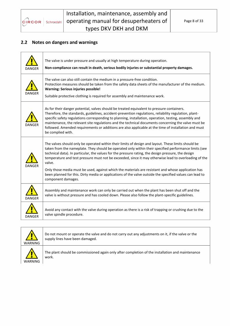
2.2 Notes on dangers and warnings
DANGER
The valve is under pressure and usually at high temperature during operation.
Non-compliance can result in death, serious bodily injuries or substantial property damages.
DANGER
The valve can also still contain the medium in a pressure-free condition. Protection measures should be taken from the safety data sheets of the manufacturer of the medium. Warning: Serious injuries possible!
Suitable protective clothing is required for assembly and maintenance work.
DANGER
As for their danger potential, valves should be treated equivalent to pressure containers. Therefore, the standards, guidelines, accident-prevention regulations, reliability regulation, plant-specific safety regulations corresponding to planning, installation, operation, testing, assembly and maintenance, the relevant site regulations and the technical documents concerning the valve must be followed. Amended requirements or additions are also applicable at the time of installation and must be complied with.
DANGER
The valves should only be operated within their limits of design and layout. These limits should be taken from the nameplate. They should be operated only within their specified performance limits (see technical data). In particular, the values for the pressure rating, the design pressure, the design temperature and test pressure must not be exceeded, since it may otherwise lead to overloading of the valve.
Only those media must be used, against which the materials are resistant and whose application has been planned for this. Dirty media or applications of the valve outside the specified values can lead to component damages.
DANGER
Assembly and maintenance work can only be carried out when the plant has been shut off and the valve is without pressure and has cooled down. Please also follow the plant-specific guidelines.
DANGER
Avoid any contact with the valve during operation as there is a risk of trapping or crushing due to the valve spindle procedure.
WARNING
Do not mount or operate the valve and do not carry out any adjustments on it, if the valve or the supply lines have been damaged.
WARNING
The plant should be commissioned again only after completion of the installation and maintenance work.
Installation, maintenance, assembly and operating manual for desuperheaters of
types DKV DKH and DKM
Page 9 of 33
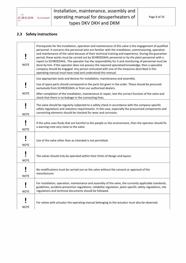
2.3 Safety instructions
NOTE
Prerequisite for the installation, operation and maintenance of this valve is the engagement of qualified personnel. It concerns the personnel who are familiar with the installation, commissioning, operation and maintenance of the valve because of their technical training and experience. During the guarantee period, these works must be carried out by SCHROEDAHL personnel or by the plant personnel with a report to SCHROEDAHL. The operator has the responsibility for it and monitoring of personnel must be done by him. If the operator does not possess the required specialised knowledge, then a specialist company should be engaged. Any person entrusted with one of the measures described in this operating manual must have read and understood this manual.
NOTE
Use appropriate tools and devices for installation, maintenance and assembly.
Use of spare parts should correspond to the parts list given in the order. These should be procured exclusively from SCHROEDAHL or from our authorised dealers.
After completion of the installation, maintenance or repair, test the correct function of the valve and check that there is no leakage in the connecting lines.
NOTE
The valve should be regularly subjected to a safety check in accordance with the company-specific safety regulations and statutory requirements. In this case, especially the pressurised components and connecting elements should be checked for wear and corrosion.
NOTE
If the valve uses fluids that are harmful to the people or the environment, then the operator should fix a warning note very close to the valve.
NOTE
Use of the valve other than as intended is not permitted.
NOTE
The valves should only be operated within their limits of design and layout.
NOTE
No modifications must be carried out on the valve without the consent or approval of the manufacturer.
NOTE
For installation, operation, maintenance and assembly of the valve, the currently applicable standards, guidelines, accident-prevention regulations, reliability regulation, plant-specific safety regulations, site regulations and technical documents should be followed.
NOTE
For valves with actuator the operating manual belonging to the actuator must also be observed.

Installation, maintenance, assembly and operating manual for desuperheaters of
types DKV DKH and DKM
Page 10 of 33
3 Delivery condition
The valves should be sent from the works in a dry and good condition. The port holes should be closed with plastic caps or such like.
Depending on the size on a pallet, the valve is shipped in a skid-carton or a wooden crate. The warnings on the packing must be followed. Special packing and conservation for larger periods of time must be indicated separately in the purchase order.
Transportation, unloading and lifting of the delivery unit must be carried out with the required caution as well as using tools that correspond to the weight and the dimensions.
Check the packaging for integrity at the time of delivery.
Check the scope of supply for completeness.
Check whether the identification of the valve on the name plate (see Chapter 5.8 Identification of the vale) corresponds to your order.
In the case of damage, incomplete or incorrect delivery, contact your forwarding agent, the person engaged for transportation or us.
NOTE
We accept no liability for damages resulting from improper transportation, loading or unloading.

Installation, maintenance, assembly and operating manual for desuperheaters of
types DKV DKH and DKM
Page 11 of 33
4 Transport and storage
WARNING
Improper transportation can cause property damages to a significant extent.
WARNING
Appropriate transportation and lifting devices must be used. For weights, see dimension sheet.
WARNING
The valve should be protected against external force (impact, shock, vibration, etc.).
During transportation and intermediate storage, the following points should be respected.
The valve should be stored in a dry, clean, well-ventilated and safe place until the assembly.
The transportation and storage temperature should be between -10 °C and +50 °C. When stored below -10 °C, our winter inerting regulations must be observed.
Any damage to the corrosion protection (painting) should be immediately rectified.
If the storage is to be done for a longer period of time (longer than 6 months), special packing and conservation must be specially planned by you.
For an interim storage over 6 months we recommend to remove the packing gland pack, in order to prevent moisture-induced corrosion between the housing wall and the spindle. This is not necessary when the complete valve is conserved.
Keep the valve using the factory protective measures (foils, boxes, pallets, etc.) The flange plugs must be removed only at the place of operation.
Installation position, dimensions and weight of the valve should be documented in the dimension sheet and complied with.
In the case of valves with a weight of over 25 kg, it is necessary to ensure that mounting lugs and lifting tools are available above the mounting location to a sufficient height.

Installation, maintenance, assembly and operating manual for desuperheaters of
types DKV DKH and DKM
Page 12 of 33
5 Description and technical data
5.1 Intended Use
DANGER
The valves should only be operated within their limits of design and layout. These limits should be taken from the nameplate. They should be operated only within their specified performance limits (see technical data). In particular, the values for the pressure rating, the design pressure, the design temperature and test pressure must not be exceeded, since it may otherwise lead to overloading of the valve. Only those media must be used, against which the materials are resistant. Dirty media or applications of the valve outside the specified values can lead to component damages.
WARNING
In the piping system, the usual flow velocities for continuous operation should not be exceeded. Operating conditions such as vibration, pressure surges, cavitation and ingredients of solid materials (in particular abrasive materials) in the medium must be clarified with the manufacturer in advance.
5.2 Description and operation
The valves are used to control the temperature of superheated steam and are selected according to the requirements of the Schroedahl data sheet.
The temperature reduction of the steam takes place by injecting finely atomized coolant (water) into the steam line controlled by the valve. The control of the coolant quantity is achieved by axially displacing the valve spindle or the valve body.
The position of the valve stem is indicated on the stroke display.

Installation, maintenance, assembly and operating manual for desuperheaters of
types DKV DKH and DKM
Page 13 of 33
5.3 Identification of the valve
The specific technical data of the valve are mentioned on the nameplate. The nameplate is fixed on each valve housing and should not be removed. The identification includes at least the following details:
Name of the manufacturer
Nominal width
PN designation
Maximum allowable pressure PS
Maximum allowable temperature TS
Test pressure PT
Material
Order number (serial number)
Type of valve
Year of manufacture
CE marking (if necessary and possible)
NOTE
In the case of spare part deliveries, basically the order number (serial number), the type and the part number from the parts list should be mentioned.
If within an order item several valves are supplied, then the nameplates should be additionally marked with a serial number beginning with "1". This ensures that the corresponding valves can be related.

Installation, maintenance, assembly and operating manual for desuperheaters of
types DKV DKH and DKM
Page 14 of 33
6 Installation of the valve in the plant
6.1 Please observe before the installation in the pipeline!
DANGER
The valve must be installed when the pipeline is in a cooled condition. Valves, which are operated with high or low temperatures (T > 60 °C or T < 0 °C), must be protected against accidental contact.
WARNING
The fitting is positioned at the predefined position of the piping, taking into account the direction of flow and is mounted free of stress. It should be ensured that the flange pads and the seals are clean and free of damages, before tightening the bolts with the torque wrench for the appropriate tightening torque. Use only the provided bolts and seals of the manufacturer for installation of the valve in the plumbing system.
WARNING
The valves are installed in such a way that the cooling medium is injected in the flow direction of the steam.
WARNING
Remove flange covers, if present.
WARNING
The interiors of the valve and the pipeline must be free of foreign particles.
WARNING
For assembly work, appropriate transportation and lifting devices must be used. For weights, see catalogue sheet.
NOTE
In order to avoid damages to the flange pads and/or bolts, the valve assembly must be mounted in the plumbing system without stress.
NOTE
If no installation location has been agreed, the fitting must be installed with the spindle directed vertically upwards. Another installation is only possible after consultation with SCHROEDAHL. For a horizontal installation a support or suspension of the actuator according to the dimension sheet may be necessary.
INFORMATION
To prevent contamination we recommend installing a sieve with a mesh width of 0.1 mm in front of the valve.

Installation, maintenance, assembly and operating manual for desuperheaters of
types DKV DKH and DKM
Page 15 of 33
Unless agreed by a separate specification, the following should be considered prior to installation of the valve:
Removal of the protective caps.
Installation position, dimensions and weight of the valve should be documented in the dimension sheet and
complied with.
In the case of valves with a weight of over 25 kg, it is necessary to ensure that mounting lugs and lifting tools
are available above the mounting location to a sufficient height.
For valves weighing more than 100 kg the center of gravity is also documented in the dimension sheet.
Prior to installation, the details of materials, pressure and temperature should be compared with the design
and operating conditions of the plumbing system.
Verification of identification on the nameplate with the operating data of the system. Any mismatch may lead
to significant damages of valves, for which the manufacturer shall not be liable.
Check that sufficient space (hoist for assembly, etc.) is available at the installation location for easy installation
and removal.
Check that the pipeline has been flushed and cleaned before installation. If not, the manufacturer accepts no
liability for the resulting damages.
Check that the distance between pipe ends matches the valve length.
Plumbing system must be correctly installed so that mechanical stresses (e.g., forces and moments from
pipeline expansions during the operation, vibrations, etc.) do not act on the valve housing during installation
and operation.
Pipeline forces can be applied by the valve only to the extent, as they were considered by the specified
pressure classes (flange geometry) and selection of material while planning the pipe system. Additional
requirements need a special confirmation.

Installation, maintenance, assembly and operating manual for desuperheaters of
types DKV DKH and DKM
Page 16 of 33
6.2 Installation of the valve
6.2.1 Valves with flanges
The sealing surfaces of the attachment flanges must be clean and without damages.
Flange gaskets must be mounted centrally and should not constrict the flow space.
The flanges should be carefully aligned before bolting. All provided flange holes must be used for the flange attachment. The bolts must be tightened according to the specifications given in the plumbing plan.
6.2.2 Valves with welding ends
NOTE
It is pointed out that the valves are welded by qualified personnel with appropriate tools and according to established engineering practices. The responsibility rests with the plant operator.
The welding process should be chosen according to the specifications given in the plumbing plan.
While welding the valve, the valve housing must not be used to test the welding electrode or the polarity.
The valve is to be in the open position during the welding process and any subsequent heat treatment. If sufficient heat removal is not possible the inner parts must be removed.
Figure 1 Typical representation of the handling options when installing the valve Left vertical lifting, right horizontal lifting.

Installation, maintenance, assembly and operating manual for desuperheaters of
types DKV DKH and DKM
Page 17 of 33
7 Pickling and flushing The materials used in the valve are in general suitable for pickling. In practice, during pickling and flushing, impurities and foreign objects pass through the valves. This may result in damages to the inner parts.
Therefore, we recommend to replace the trims with appropriate protective inserts prior to pickling or flushing.
After pickling and flushing, the valve must be cleaned and the seals must be replaced.
NOTE
Any foreign object, which remains in the valve after pickling or flushing, may damage the valve.
8 Disassembly
DANGER
The valve must be without pressure, drained and in cooled condition. The actuator must be disconnected from the power supply.
Observe the notes in the dimension sheet and in the drive documentation.
8.1 Valves with flanges
1. Suspend the valve, but do not lift; see Figure 1.Fehler! Verweisquelle konnte nicht gefunden werden.
2. Remove the flange bolts.
3. Remove the valve from the pipeline.
4. Store the valve in a protected condition.
NOTE
The flange sealing surfaces of the valve must not be damaged during the removal of the pipeline and must be closed with suitable plastic caps or such like.
8.2 Valves with welding ends
For valves with welding ends, the housing cannot be removed. This requires a mechanical destruction of the connection of housing and pipeline or the plumbing system allows a displacement of the pipe parts (responsibility of the plant operator).

Installation, maintenance, assembly and operating manual for desuperheaters of
types DKV DKH and DKM
Page 18 of 33
9 Disassembly and assembly of the valve
9.1 General assembly and disassembly information
Due to the high precision and close tolerances, maximum cleanliness and proper handling should be ensured. Any contamination or damage puts the proper operation in jeopardy.
DANGER
Before disassembling the valve, the valve must be without pressure, drained and in cooled condition! The actuator must be disconnected from the power supply and/or secured against unauthorised switching on.
WARNING
Before beginning any work ensure the following:
Work correctly and safely according to the applicable regulations as well as the warnings and notes in this operating manual.
Valves are pressure devices! Any improper opening of the valve can endanger your health! The plant must be pressureless and dry before disassembly.
Block the pipeline upstream and downstream of the valve.
Remove the pressure from the pipe section.
Allow the valve to cool to room temperature.
Find out from the safety data sheet about the contents of the line and properly drain all hazardous and/or groundwater-endangering media from the blocked pipe section.
Ensure the personal protective equipment prescribed in the safety data sheet.
Immediately wipe away leakages and/or collect larger amounts or residues of medium in suitable containers.
Always properly dispose of residues of medium (only in the case of hazardous media) in accordance with the Law on Waste. Never allow leakages/residues of medium seep into the sewerage system.
WARNING
Remove flange covers, if present.

Installation, maintenance, assembly and operating manual for desuperheaters of
types DKV DKH and DKM
Page 19 of 33
WARNING
The interiors of the valve and the pipeline must be free of foreign particles.
WARNING
Installation position of the valve with respect to the flow should be correctly maintained; see identification on the valve.
WARNING
Appropriate transportation and lifting devices must be used for assembly work. For weights, see dimension sheet.
WARNING
Special safety regulations and risk analyses must be performed before any maintenance, so that risks to humans and the environment are excluded!

Installation, maintenance, assembly and operating manual for desuperheaters of
types DKV DKH and DKM
Page 20 of 33
9.2 Actuator
There are different variants (lamps, distance bolts etc.) in the valve assembly for fixing the actuator, therefore the sectional drawing of the valve and the instructions of the drive manufacturer are required for the disassembly and assembly.
It should be noted that the control piston is driven out of the seat by the valve spindle in order to interrupt a flow of force between the spindle and the drive.
9.3 Gearbox
In the case of valves with a rotary drive a gear is necessary for converting the rotary movement into a thrust movement. In the Schroedahl scope of delivery this is referred to as the gearbox
The position numbers in this description correspond to the position numbers of the intersection drawing.
9.3.1 Disassembly
Loosen the cylinder screws (item 38) on the coupling
Remove both clutch halves (item 36)
Loosen nuts (item 35) or cylinder screws (item 59)
Lift the gearbox (item 21)
Unscrew the cylinder screws (item 33) on the gearbox
Tighten the clamping ring (item 26) with a commercially available spanner
WARNING
The clamping ring (item 26) is under high pretension due to the disc springs!
If no new parts are used it is advisable to mark the distance and the position of the clamping ring so that the pre-stressing can be restored during assembly.
Disc springs (item 27 and/or item 28) are preloaded. To relieve the disc springs (item 27 and/or item 28) place the complete gearbox without a threaded spindle (item 25) under a press. The bearing surfaces are the spindle nut (item 24) and the actuator drive flange of the gearbox. After application of the pretension force the clamping ring (item 26) is loosened by a half-turn with a face spanner.
Now the inner parts of the actuator can be removed one after the other.
Installation, maintenance, assembly and operating manual for desuperheaters of
types DKV DKH and DKM
Page 21 of 33
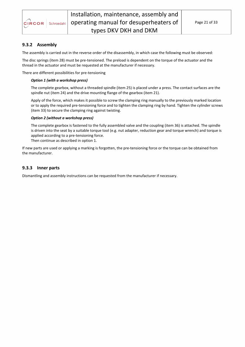
9.3.2 Assembly
The assembly is carried out in the reverse order of the disassembly, in which case the following must be observed:
The disc springs (item 28) must be pre-tensioned. The preload is dependent on the torque of the actuator and the thread in the actuator and must be requested at the manufacturer if necessary.
There are different possibilities for pre-tensioning
Option 1 (with a workshop press)
The complete gearbox, without a threaded spindle (item 25) is placed under a press. The contact surfaces are the spindle nut (item 24) and the drive mounting flange of the gearbox (item 21).
Apply of the force, which makes it possible to screw the clamping ring manually to the previously marked location or to apply the required pre-tensioning force and to tighten the clamping ring by hand. Tighten the cylinder screws (item 33) to secure the clamping ring against twisting.
Option 2 (without a workshop press)
The complete gearbox is fastened to the fully assembled valve and the coupling (item 36) is attached. The spindle is driven into the seat by a suitable torque tool (e.g. nut adapter, reduction gear and torque wrench) and torque is applied according to a pre-tensioning force. Then continue as described in option 1.
If new parts are used or applying a marking is forgotten, the pre-tensioning force or the torque can be obtained from the manufacturer.
9.3.3 Inner parts
Dismantling and assembly instructions can be requested from the manufacturer if necessary.

Installation, maintenance, assembly and operating manual for desuperheaters of
types DKV DKH and DKM
Page 22 of 33
10 Commissioning
WARNING
The valves must not be operated outside the permissible fields of application. These limits should be taken from the nameplate.
WARNING
Residues in pipelines and valves (such as dirt, welding beads, etc.) cause leakages or damages.
WARNING
When operating at high (> 50 °C) or low (< 0 °C) temperatures of the media, there is risk of injury when touching the valve. If necessary, put up warnings or make insulation protection!
WARNING
Before each commissioning, after reworks and repairs, proper completion of all installation works must be ensured.
NOTE
Thermal stresses in the pressure bearing housing parts can also lead to damage. We therefore recommend keeping the heating rate within the usual limits of 5°C / min.
NOTE
If the valve is operated with other operating data, then increased wear of the parts should be expected, depending on the variation in the design data. In the case of changed operating data, we recommend to consult the manufacturer, so that the valve can be specifically set to the operating conditions.
NOTE
After commissioning, an inspection of the valve is recommended, in order to ensure that there are no damages to the valve!
NOTE
The valve and the pipeline must be free of contamination.

Installation, maintenance, assembly and operating manual for desuperheaters of
types DKV DKH and DKM
Page 23 of 33
11 Maintenance
WARNING
Servicing and maintenance works must be carried out only by qualified personnel!
The valve is maintenance-free with the exception of checking the packing gland and lubrication for rotary actuators.
DANGER
The valve is under pressure and usually at high temperature during operation. Non-compliance can result in death, serious bodily injuries or property damages.
Assembly and maintenance work can only be carried out when the plant has been shut off and the valve is without pressure and has cooled down.
The plant should be commissioned again only after completion of the installation and maintenance work.
DANGER
The valve can also still contain the medium in a pressure-free condition. Protection measures should be taken from the safety data sheets of the manufacturer of the medium! WARNING: Serious injuries possible! Suitable protective clothing is required for assembly and maintenance work.
NOTE
When removing the valve from the pipeline do not damage the flange sealing surfaces and close them with suitable means.
NOTE
The spindle seal must be regularly checked for leaks. Leaks must first be removed by suitably tightening the packing gland nuts (item 54). If the leakage persists a packing ring can be added or the packing gland can be repacked. See Chapter "Packing gland".
NOTE
In the case of valves with an electric rotary drive, the spindle nut must be checked for sufficient lubrication at regular intervals and if necessary re-lubricated. See Chapter "Lubrication".
NOTE
The ball bearing located in the gearbox (item 29/30) should be lubricated approximately quarterly via the grease nipple (item 34), if necessary at shorter intervals. It must be lubricated until the grease flows out over the head of the thread spindle.
NOTE
Observe the maintenance instructions of the drive manufacturer.

Installation, maintenance, assembly and operating manual for desuperheaters of
types DKV DKH and DKM
Page 24 of 33
11.1 Packing gland
The packing gland provides the seal between the valve spindle and the housing opposite the flowing medium inside the valve. It is a wear part and must be renewed if necessary.
The number and arrangement of the packing rings (item 11.1 and item 11.2) is specified by the parts list in conjunction with the sectional drawing.
The chamber, as base and cover ring, forms in each case the packing ring item 11.2. The packing rings (items 11.1 and 11.2) can look the same and should not be confused. For split rings the impact points, Fehler! Verweisquelle konnte nicht gefunden werden., are to be offset by 90°.
When assembling the packing rings insert the individual rings into the packing gland and press them towards the packing gland base.
Place the packing follower (item 9) and packing gland (item 53) and lightly tighten the nuts (item 54).
Compress the packing gland packet onto the ¾ of the required path L by tightening the packing gland evenly. Then move the spindle in the direction of the packing gland base and apply the remaining pressing action for the operating condition.
The required compression path L is generally indicated as L = 0.05 × packing height.
If necessary a torque for tightening the packing gland is also indicated on the sectional drawing.
For sealing, the pack must be compressed more. If the fitting is too stiff, the pack can be compressed less - but always pay attention to tightness!
Finally check the operability of the valve by running the spindle several times.
NOTE
When installing the package the spindle and mounting space must be clean and in perfect condition.
Figure 2 Impact points offset by 90°

Installation, maintenance, assembly and operating manual for desuperheaters of
types DKV DKH and DKM
Page 25 of 33
11.2 Lubrication
In the case of valves with a rotary drive the thread spindle (item 25) should be treated with a suitable lubricant approximately every two months.
The gearbox itself and thus the ball bearings located therein should be lubricated via the grease nipple (item 34) approximately quarterly.
It is recommended to disassemble the gearbox every two to three years, clean the parts and re-grease every. For disassembly and assembly of the gearbox refer to Chapter 11.
As lubrication for the parts of the gearbox we recommend:
Varilub, long-term lubricant
It is also possible to use a lubricant of quality similar from other manufacturers.
Installation, maintenance, assembly and operating manual for desuperheaters of
types DKV DKH and DKM
Page 26 of 33
12 Inspections and inspection schedules
12.1 Inspections
The valve has been designed and manufactured, such that maximum quality and service friendliness is achieved. This results in a lower need for care and maintenance of the valve.
Necessary checks before commissioning and after significant changes in the plant and repetitive checks should be carried out by the operator as required by the regulations.
A complete valve performance test run is recommended to be done together with the original pump.
The bypass Kv/Cv value test can be certified at our test facility.
Please contact SCHROEDAHL for additional information.
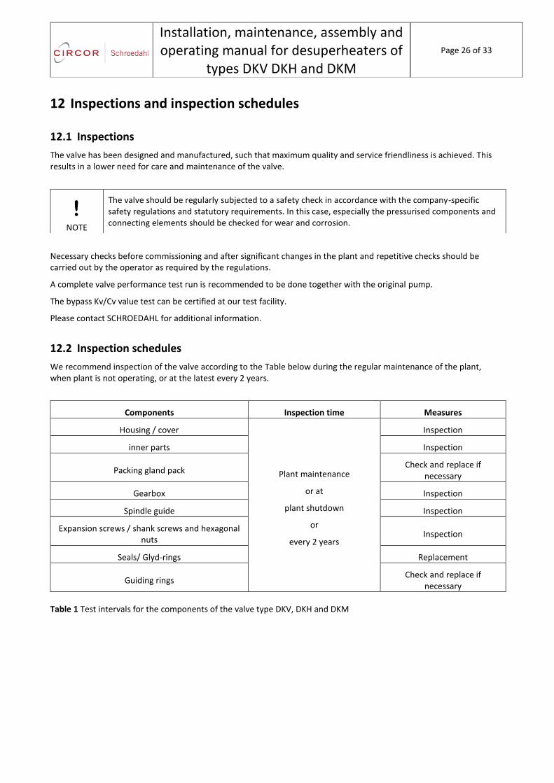
12.2 Inspection schedules
We recommend inspection of the valve according to the Table below during the regular maintenance of the plant, when plant is not operating, or at the latest every 2 years.
Components Inspection time Measures
Housing / cover
Plant maintenance
or at
plant shutdown
or
every 2 years
Inspection
inner parts Inspection
Packing gland pack Check and replace if
necessary
Gearbox Inspection
Spindle guide Inspection
Expansion screws / shank screws and hexagonal nuts
Inspection
Seals/ Glyd-rings Replacement
Guiding rings Check and replace if
necessary
Table 1 Test intervals for the components of the valve type DKV, DKH and DKM
NOTE
The valve should be regularly subjected to a safety check in accordance with the company-specific safety regulations and statutory requirements. In this case, especially the pressurised components and connecting elements should be checked for wear and corrosion.
Installation, maintenance, assembly and operating manual for desuperheaters of
types DKV DKH and DKM
Page 27 of 33
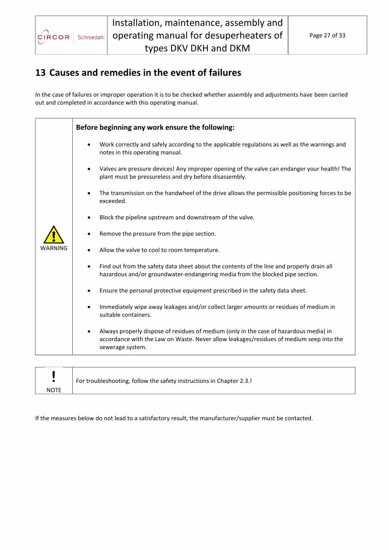
13 Causes and remedies in the event of failures
In the case of failures or improper operation it is to be checked whether assembly and adjustments have been carried out and completed in accordance with this operating manual.
WARNING
Before beginning any work ensure the following:
Work correctly and safely according to the applicable regulations as well as the warnings and notes in this operating manual.
Valves are pressure devices! Any improper opening of the valve can endanger your health! The plant must be pressureless and dry before disassembly.
The transmission on the handwheel of the drive allows the permissible positioning forces to be exceeded.
Block the pipeline upstream and downstream of the valve.
Remove the pressure from the pipe section.
Allow the valve to cool to room temperature.
Find out from the safety data sheet about the contents of the line and properly drain all hazardous and/or groundwater-endangering media from the blocked pipe section.
Ensure the personal protective equipment prescribed in the safety data sheet.
Immediately wipe away leakages and/or collect larger amounts or residues of medium in suitable containers.
Always properly dispose of residues of medium (only in the case of hazardous media) in accordance with the Law on Waste. Never allow leakages/residues of medium seep into the sewerage system.
If the measures below do not lead to a satisfactory result, the manufacturer/supplier must be contacted.
NOTE
For troubleshooting, follow the safety instructions in Chapter 2.3.!

Installation, maintenance, assembly and operating manual for desuperheaters of
types DKV DKH and DKM
Page 28 of 33
Defects No. Possible causes Measures
1. No flow 1.1 Flange covers (transportation
protection) not removed Remove flange covers
(transportation protection)
2. Low valve flow
2.1 Contaminated strainer (dirt trap) Clean or replace the strainer
2.2 Blockage in the plumbing system Check the plumbing system
2.3 Wear or damage of the valve due to vapour and condensation shocks and cavitation
Replace the valve
2.4
The valve not installed in direction of flow
Install the valve in the direction of flow
3. Leakage of valve seat
3.1 Incorrect setting or failure of the end or torque switches on the actuator
Check that the drive is in the correct position. If necessary check whether the end position has been reached using the actuator handwheel.
3.2 Damage to the seat due to foreign body
For simple damage to the valve seat see the instruction "Grinding the housing seat". This can be ordered from the manufacturer.
3.3 The deformation of the seat surface due to incorrect operation via the handwheel of the drive.
If the leakage cannot be eliminated, new spare parts and the associated seals must be used. These are available from the manufacturer.
Installation, maintenance, assembly and operating manual for desuperheaters of
types DKV DKH and DKM
Page 29 of 33
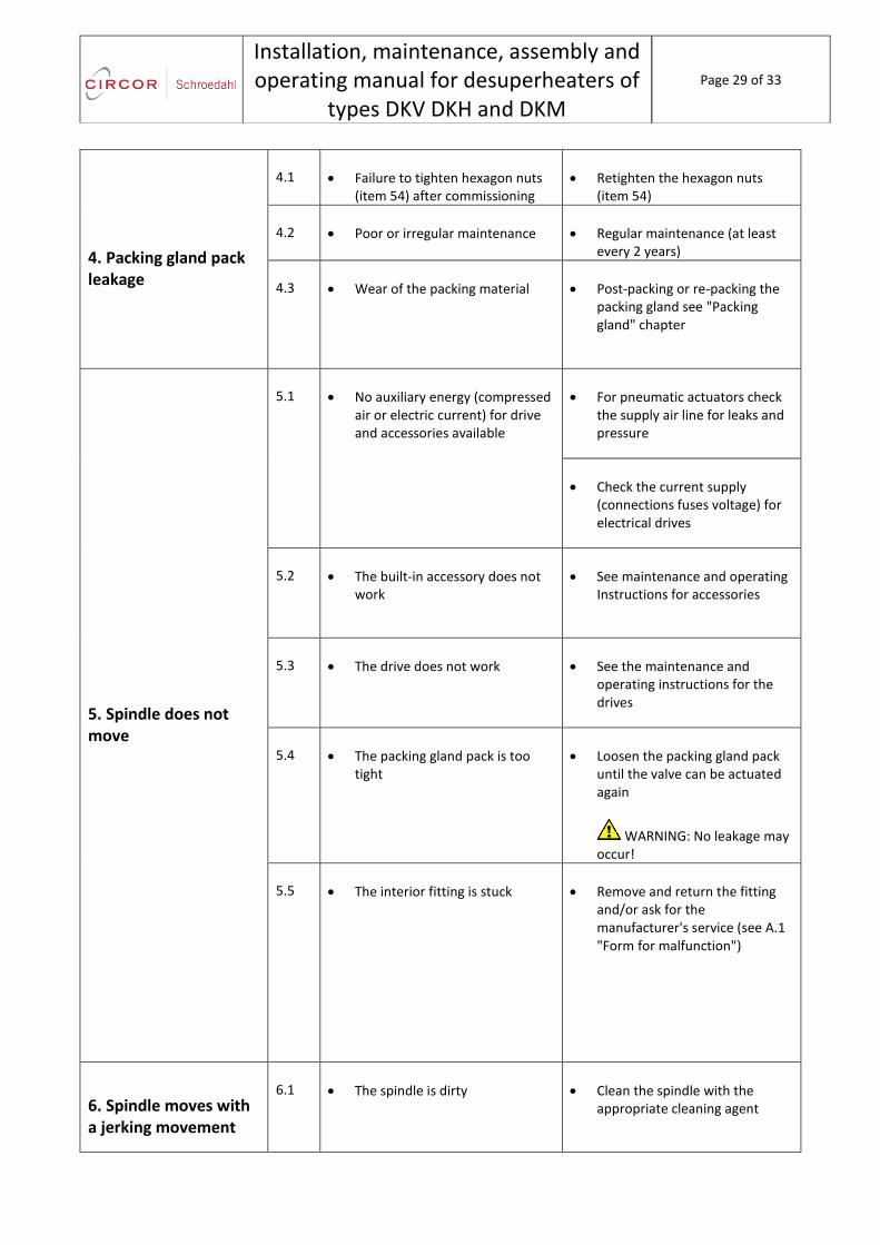
4. Packing gland pack leakage
4.1 Failure to tighten hexagon nuts (item 54) after commissioning
Retighten the hexagon nuts (item 54)
4.2 Poor or irregular maintenance Regular maintenance (at least every 2 years)
4.3
Wear of the packing material Post-packing or re-packing the packing gland see "Packing gland" chapter
5. Spindle does not move
5.1 No auxiliary energy (compressed air or electric current) for drive and accessories available
For pneumatic actuators check the supply air line for leaks and pressure
Check the current supply (connections fuses voltage) for electrical drives
5.2 The built-in accessory does not work
See maintenance and operating Instructions for accessories
5.3 The drive does not work See the maintenance and operating instructions for the drives
5.4 The packing gland pack is too tight
Loosen the packing gland pack until the valve can be actuated again
WARNING: No leakage may occur!
5.5 The interior fitting is stuck Remove and return the fitting and/or ask for the manufacturer's service (see A.1 "Form for malfunction")
6. Spindle moves with a jerking movement
6.1 The spindle is dirty Clean the spindle with the appropriate cleaning agent

Installation, maintenance, assembly and operating manual for desuperheaters of
types DKV DKH and DKM
Page 30 of 33
6.2 The spindle is damaged Remove and return the fitting and/or ask for the manufacturer's service
6.3 The drive force is too low Compare the drive data of the type plate with the operating data of the system - inform manufacturer / supplier if it is different
6.4 The packing gland pack is too tight
See 5.4
7. Spindle does not move over the entire stroke range (0 to 100% stroke)
7.1 Too low supply pressure for pneumatic drives
Check the required supply air pressure from the type plate
7.2 Misaligned handwheel for pneumatic actuators with manual override
Move the handwheel into the zero position (see operating manual drive)
7.3 Misaligned limit switch for electric drives
Adjust the limit switch according to the drive manufacturer specifications
7.4 Misaligned or defective positioner
Adjust positioner according to the manufacturer's instructions
7.5
Foreign bodies in the valve seat, damaged inner parts
Remove and return the fitting and/or ask for the manufacturer's service
Modify the drive spindle connection by adjusting the thread
8. Valve stiffness 8.1 Packing gland pack compressed
too much Slightly loosen the hexagon nuts
(item 54) but only to the extent that the seal still exists
Installation, maintenance, assembly and operating manual for desuperheaters of
types DKV DKH and DKM
Page 31 of 33
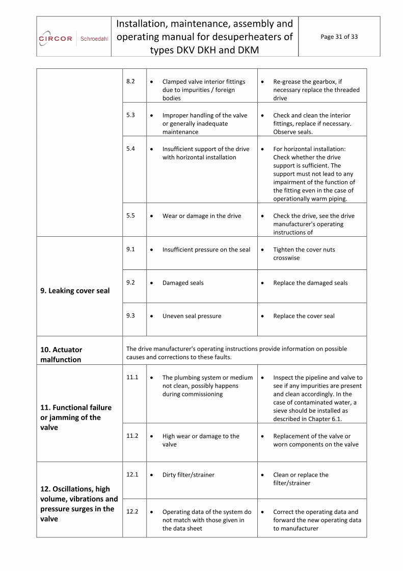
8.2 Clamped valve interior fittings due to impurities / foreign bodies
Re-grease the gearbox, if necessary replace the threaded drive
5.3 Improper handling of the valve or generally inadequate maintenance
Check and clean the interior fittings, replace if necessary. Observe seals.
5.4 Insufficient support of the drive with horizontal installation
For horizontal installation: Check whether the drive support is sufficient. The support must not lead to any impairment of the function of the fitting even in the case of operationally warm piping.
5.5 Wear or damage in the drive Check the drive, see the drive manufacturer's operating instructions of
9. Leaking cover seal
9.1
Insufficient pressure on the seal Tighten the cover nuts crosswise
9.2
Damaged seals Replace the damaged seals
9.3
Uneven seal pressure Replace the cover seal
10. Actuator malfunction
The drive manufacturer's operating instructions provide information on possible causes and corrections to these faults.
11. Functional failure or jamming of the valve
11.1 The plumbing system or medium not clean, possibly happens during commissioning
Inspect the pipeline and valve to see if any impurities are present and clean accordingly. In the case of contaminated water, a sieve should be installed as described in Chapter 6.1.
11.2 High wear or damage to the valve
Replacement of the valve or worn components on the valve
12. Oscillations, high volume, vibrations and pressure surges in the valve
12.1 Dirty filter/strainer Clean or replace the filter/strainer
12.2 Operating data of the system do not match with those given in the data sheet
Correct the operating data and forward the new operating data to manufacturer

Installation, maintenance, assembly and operating manual for desuperheaters of
types DKV DKH and DKM
Page 32 of 33
12.3 Damaged trim parts Inspection of the valve: clean or replace trim parts
12.4 Inlet or outlet section on the valve too short
Straight piping of approx. 10 x DN but at least 2 m upstream and downstream of the valve
12.5 Fittings or junctions within the inlet or outlet section
Straight inlet and outlet (avoid bow) without fittings
Table 2 Causes and measures for malfunctions of the valve type DKV, DKH and DKM
Installation, maintenance, assembly and operating manual for desuperheaters of
types DKV DKH and DKM
Page 33 of 33
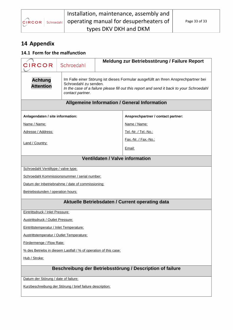
14 Appendix
14.1 Form for the malfunction
Meldung zur Betriebsstörung / Failure Report
Achtung
Attention
Im Falle einer Störung ist dieses Formular ausgefüllt an Ihren Ansprechpartner bei Schroedahl zu senden. In the case of a failure please fill out this report and send it back to your Schroedahl contact partner.
Allgemeine Information / General Information
Anlagendaten / site information:
Name / Name:
Adresse / Address:
Land / Country:
Ansprechpartner / contact partner:
Name / Name:
Tel.-Nr. / Tel.-No.:
Fax.-Nr. / Fax.-No.:
Email:
Ventildaten / Valve information Schroedahl Ventiltype / valve type:
Schroedahl Kommissionsnummer / serial number:
Datum der Inbetriebnahme / date of commissioning:
Betriebsstunden / operation hours:
Aktuelle Betriebsdaten / Current operating data
Eintrittsdruck / Inlet Pressure:
Austrittsdruck / Outlet Pressure:
Eintrittstemperatur / Inlet Temperature:
Austrittstemperatur / Outlet Temperature:
Fördermenge / Flow Rate:
% des Betriebs in diesem Lastfall / % of operation of this case:
Hub / Stroke:
Beschreibung der Betriebsstörung / Description of failure
Datum der Störung / date of failure:
Kurzbeschreibung der Störung / brief failure description: